WO2022158179A1 - 履帯式作業機械 - Google Patents
履帯式作業機械 Download PDFInfo
- Publication number
- WO2022158179A1 WO2022158179A1 PCT/JP2021/046213 JP2021046213W WO2022158179A1 WO 2022158179 A1 WO2022158179 A1 WO 2022158179A1 JP 2021046213 W JP2021046213 W JP 2021046213W WO 2022158179 A1 WO2022158179 A1 WO 2022158179A1
- Authority
- WO
- WIPO (PCT)
- Prior art keywords
- steering
- turning
- clutch
- mode
- controller
- Prior art date
- Legal status (The legal status is an assumption and is not a legal conclusion. Google has not performed a legal analysis and makes no representation as to the accuracy of the status listed.)
- Ceased
Links
Images

Classifications
-
- B—PERFORMING OPERATIONS; TRANSPORTING
- B62—LAND VEHICLES FOR TRAVELLING OTHERWISE THAN ON RAILS
- B62D—MOTOR VEHICLES; TRAILERS
- B62D11/00—Steering non-deflectable wheels; Steering endless tracks or the like
- B62D11/02—Steering non-deflectable wheels; Steering endless tracks or the like by differentially driving ground-engaging elements on opposite vehicle sides
- B62D11/06—Steering non-deflectable wheels; Steering endless tracks or the like by differentially driving ground-engaging elements on opposite vehicle sides by means of a single main power source
- B62D11/10—Steering non-deflectable wheels; Steering endless tracks or the like by differentially driving ground-engaging elements on opposite vehicle sides by means of a single main power source using gearings with differential power outputs on opposite sides, e.g. twin-differential or epicyclic gears
- B62D11/14—Steering non-deflectable wheels; Steering endless tracks or the like by differentially driving ground-engaging elements on opposite vehicle sides by means of a single main power source using gearings with differential power outputs on opposite sides, e.g. twin-differential or epicyclic gears differential power outputs being effected by additional power supply to one side, e.g. power originating from secondary power source
- B62D11/18—Steering non-deflectable wheels; Steering endless tracks or the like by differentially driving ground-engaging elements on opposite vehicle sides by means of a single main power source using gearings with differential power outputs on opposite sides, e.g. twin-differential or epicyclic gears differential power outputs being effected by additional power supply to one side, e.g. power originating from secondary power source the additional power supply being supplied hydraulically
- B62D11/183—Control systems therefor
-
- B—PERFORMING OPERATIONS; TRANSPORTING
- B62—LAND VEHICLES FOR TRAVELLING OTHERWISE THAN ON RAILS
- B62D—MOTOR VEHICLES; TRAILERS
- B62D11/00—Steering non-deflectable wheels; Steering endless tracks or the like
- B62D11/02—Steering non-deflectable wheels; Steering endless tracks or the like by differentially driving ground-engaging elements on opposite vehicle sides
- B62D11/04—Steering non-deflectable wheels; Steering endless tracks or the like by differentially driving ground-engaging elements on opposite vehicle sides by means of separate power sources
-
- E—FIXED CONSTRUCTIONS
- E02—HYDRAULIC ENGINEERING; FOUNDATIONS; SOIL SHIFTING
- E02F—DREDGING; SOIL-SHIFTING
- E02F9/00—Component parts of dredgers or soil-shifting machines, not restricted to one of the kinds covered by groups E02F3/00 - E02F7/00
- E02F9/20—Drives; Control devices
- E02F9/22—Hydraulic or pneumatic drives
-
- E—FIXED CONSTRUCTIONS
- E02—HYDRAULIC ENGINEERING; FOUNDATIONS; SOIL SHIFTING
- E02F—DREDGING; SOIL-SHIFTING
- E02F9/00—Component parts of dredgers or soil-shifting machines, not restricted to one of the kinds covered by groups E02F3/00 - E02F7/00
- E02F9/20—Drives; Control devices
- E02F9/22—Hydraulic or pneumatic drives
- E02F9/225—Control of steering, e.g. for hydraulic motors driving the vehicle tracks
-
- B—PERFORMING OPERATIONS; TRANSPORTING
- B62—LAND VEHICLES FOR TRAVELLING OTHERWISE THAN ON RAILS
- B62D—MOTOR VEHICLES; TRAILERS
- B62D11/00—Steering non-deflectable wheels; Steering endless tracks or the like
- B62D11/001—Steering non-deflectable wheels; Steering endless tracks or the like control systems
- B62D11/003—Electric or electronic control systems
Definitions
- the present disclosure relates to track-type work machines.
- the left and right planetary gear mechanisms are arranged between the input shaft and the left and right output shafts.
- the left and right steering clutches are rotatable about the input shaft, and switch transmission and cutoff of rotational power from the input shaft to the left and right output shafts by the left and right planetary gear mechanisms.
- the left and right steering brakes brake the left and right output shafts.
- the turning motor rotates the left and right steering clutches so that the left and right output shafts have a difference in rotational speed.
- the track-type work machine described in Patent Document 1 engages the left and right steering clutches, releases the left and right steering brakes, and stops the turning motor to move straight.
- the track-type work machine described in Patent Document 1 turns in a pivot turning mode by releasing the inner steering clutch, braking the inner steering brake, and stopping the turning motor.
- the turning speed during pivot turning can be increased by driving the turning motor.
- the inner steering clutch in the pivot turning mode, the inner steering clutch is released, so the inner planetary gear mechanism is idly rotated by the rotational power from the input shaft, and the inner steering clutch is also idly rotated by the driving force of the turning motor.
- An object of the present disclosure is to provide a track-type working machine capable of suppressing the heat load on the inner steering clutch.
- a crawler belt working machine includes left and right planetary gear mechanisms, left and right steering clutches, left and right steering brakes, a turning motor, and a controller.
- the left and right planetary gear mechanisms are arranged between the input shaft and the left and right output shafts.
- the left and right steering clutches are rotatable about the input shaft, and switch transmission and cutoff of rotational power from the input shaft to the left and right output shafts by the left and right planetary gear mechanisms.
- the left and right steering brakes brake the left and right output shafts.
- the turning motor rotates the left and right steering clutches so that the left and right output shafts have a difference in rotational speed.
- the controller controls the left and right steering clutches, left and right steering brakes, and turning motors to turn the crawler-type work machine in any one of a straight-ahead mode, a gentle turning mode, and a turning mode.
- the controller engages the left and right steering clutches, releases the left and right steering brakes, and stops the turning motor in the straight ahead mode.
- the gentle turning mode the controller engages the left and right steering clutches, releases the left and right steering brakes, and drives the turning motor.
- the controller releases the inner steering clutch corresponding to the turning direction among the left and right steering clutches, brakes the inner steering brake corresponding to the turning direction among the left and right steering brakes, and operates the turning motor. drive.
- the controller maintains the rotational speed of the turning motor until after the first timing at which the inner steering clutch begins to partially engage when the steering mode is shifted to the straight driving mode or the gentle turning mode.
- FIG. 1 is a perspective view of a bulldozer according to an embodiment
- FIG. 1 is a cross-sectional configuration diagram of a power transmission system of a bulldozer according to an embodiment
- FIG. 1 is a schematic system configuration diagram of a power transmission system of a bulldozer according to an embodiment
- 2 is a schematic system configuration diagram of a power transmission system of a bulldozer according to Modification 1.
- FIG. 1 is a perspective view of a bulldozer according to an embodiment
- FIG. 1 is a cross-sectional configuration diagram of a power transmission system of a bulldozer according to an embodiment
- FIG. 1 is a schematic system configuration diagram of a power transmission system of a bulldozer according to an embodiment
- FIG. 5 is a
- FIG. 1 is a perspective view of a bulldozer 1, which is an example of a track-type working machine.
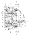
- FIG. 2 is a sectional configuration diagram of the power transmission system of the bulldozer 1.
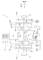
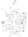
- FIG. 3 is a schematic system configuration diagram of the power transmission system of the bulldozer 1. As shown in FIG.
- the bulldozer 1 includes left and right traveling devices 4L and 4R including left and right sprockets 2L and 2R and left and right crawler belts 3L and 3R, a blade 5 provided at the front of the vehicle, and a blade 5 provided at the rear of the vehicle. and a ripper device 6.
- the bulldozer 1 can perform work such as earth pushing with the blade 5 and work such as crushing and excavation with the ripper device 6 .
- the bulldozer 1 includes an engine 10, an engine power transmission section 20, left and right planetary gear mechanisms 30L and 30R, left and right steering clutches 40L and 40R, left and right steering brakes 50L, 50R, left and right output shafts 60L and 60R, a turning motor 80, a motor power transmission section 90, and a controller 100.
- the engine power transmission section 20 transmits power from the engine 10 to the left and right planetary gear mechanisms 30L, 30R.
- the engine power transmission section 20 includes a power take-off device 21 , a torque converter 22 , a transmission 23 , a pinion 24 , a bevel gear 25 and an input shaft 26 .
- the power take-off device 21 transmits power from the engine 10 to the torque converter 22 .
- Torque converter 22 transmits the power of engine 10 transmitted from power take-off device 21 to transmission 23 via fluid.
- the transmission 23 has a plurality of speed stage clutches for shifting the rotational power transmitted from the torque converter 22 and a direction stage clutch for switching between forward and reverse.
- Transmission 23 is connected to pinion 24 .
- Power from the transmission 23 is transmitted to the input shaft 26 via the pinion 24 and bevel gear 25 .
- the input shaft 26 extends in the left-right direction.
- the axial direction of the input shaft 26 is synonymous with the lateral direction of the bulldozer 1 .
- the left and right planetary gear mechanisms 30L, 30R are arranged between the input shaft 26 and the left and right output shafts 60L, 60R.
- the left and right planetary gear mechanisms 30L, 30R have left and right ring gears 31L, 31R, left and right planetary gears 32L, 32R, left and right sun gears 33L, 33R, and left and right carriers 34L, 34R.
- the left and right ring gears 31L, 31R are connected to the input shaft 26.
- the left and right planetary gears 32L, 32R are arranged inside the left and right ring gears 31L, 31R in the radial direction perpendicular to the axial direction of the input shaft 26 .
- the left and right planetary gears 32L, 32R mesh with the left and right ring gears 31L, 31R and the left and right sun gears 33L, 33R.
- the left and right sun gears 33L, 33R are rotatably attached to the input shaft 26. As shown in FIG.
- the left and right sun gears 33L, 33R are arranged inside the left and right planetary gears 32L, 32R in the radial direction.
- the left and right sun gears 33L, 33R are connected to the left and right steering clutches 40L, 40R.
- the left and right sun gears 33L, 33R can be connected and disconnected to the motor power transmission section 90 (specifically, left and right clutch gears 91L, 91R described later) via the left and right steering clutches 40L, 40R.
- the left and right carriers 34L, 34R are connected to the left and right planetary gears 32L, 32R and the left and right output shafts 60L, 60R.
- the left and right steering clutches 40L, 40R are arranged between the left and right planetary gear mechanisms 30L, 30R and the motor power transmission section 90. As shown in FIG. The left and right steering clutches 40L, 40R separate and contact the left and right sun gears 33L, 33R of the left and right planetary gear mechanisms 30L, 30R and the left and right clutch gears 91L, 91R of the motor power transmission unit 90 .
- the left and right steering clutches 40L, 40R are driven by the supply of hydraulic oil.
- the left and right steering clutches 40L, 40R are composed of wet multi-plate clutches that can be engaged and disengaged.
- the left and right steering clutches 40L and 40R are positive type hydraulic clutches.
- the left and right steering clutches 40L and 40R are disengaged when hydraulic oil is not supplied, partially engaged when the hydraulic pressure of the supplied hydraulic oil is less than a predetermined value, and when the hydraulic pressure of the supplied hydraulic oil is equal to or higher than the predetermined value. when fully engaged.
- pivot turning means turning about the crawler belt on the other side by rotating one of the left and right output shafts 60L and 60R and substantially or completely stopping the other. do.
- the turning motor 80 is driven by the power of the engine 10 .
- the swing motor 80 rotates in either the forward rotation direction or the reverse rotation direction.
- a controller 100 controls the rotation direction and rotation speed of the swing motor 80 .
- the rotation speed of the turning motor 80 varies from 0% to 100% (maximum value) according to the power transmitted from the engine 10 .
- the rotational power of the swing motor 80 is transmitted to the left and right steering clutches 40L, 40R via the motor power transmission section 90.
- the turning motor 80 rotates the left and right steering clutches 40L, 40R so that the left and right output shafts 60L, 60R have a rotational speed difference.
- the rotation speed of the left output shaft 60L becomes higher than the rotation speed of the right output shaft 60R.
- the turning motor 80 reversely rotates the left and right steering clutches 40L and 40R. , only the left output shaft 60L rotates without rotating the right output shaft 60R.
- the motor power transmission unit 90 has left and right clutch gears 91L, 91R, a first transfer gear 92, a countershaft 93, a second transfer gear 94, an idler gear 95 and a pinion gear 96.
- the left and right clutch gears 91L, 91R can be separated from and connected to the left and right sun gears 33L, 33R via the left and right steering clutches 40L, 40R.
- the left and right clutch gears 91L, 91R are rotatable about the axial direction of the input shaft 26. As shown in FIG.
- the left clutch gear 91L meshes with the idler gear 95.
- the right clutch gear 91R is connected to an idler gear 95 via a first transfer gear 92, a countershaft 93 and a second transfer gear 94.
- the left and right clutch gears 91L and 91R rotate in opposite directions when the turning motor 80 rotates.
- the idler gear 95 meshes with the left clutch gear 91L, the second transfer gear 94 and the pinion gear 96.
- the idler gear 95 is rotatable around the axial direction of the input shaft 26 .
- the pinion gear 96 meshes with the idler gear 95.
- the pinion gear 96 is rotatable around a pinion shaft 96a.
- the pinion gear 96 is rotated by the rotational power of the turning motor 80 transmitted via the pinion shaft 96a.
- the controller 100 controls the speed of the engine 10 and the speed stage clutch and direction stage clutch of the transmission 23 in order to make the bulldozer 1 travel.
- the controller 100 controls the left and right steering clutches 40L, 40R, the left and right steering brakes 50L, 50R, and the turning motor 80 to operate in any one of the "straight ahead mode", "slow turning mode” and "pivot turning mode”. Run bulldozer 1.
- the controller 100 controls the left and right clutch control valves 27L, 27R to completely engage the left and right steering clutches 40L, 40R.
- the inner output shaft 60 IN is one of the left and right output shafts 60L and 60R that corresponds to the operating direction (that is, turning direction) of the steering lever 35 .
- the outer output shaft 60 OUT is the output shaft of the left and right output shafts 60L, 60R opposite to the operating direction of the steering lever 35 .
- the inner steering clutch 40 IN is a steering clutch corresponding to the operation direction of the steering lever 35 among the left and right steering clutches 40L and 40R.
- the outer steering clutch 40 OUT is the steering clutch of the left and right steering clutches 40L, 40R that is opposite to the operating direction of the steering lever 35 .
- the inner steering brake 50 IN is a steering brake corresponding to the operating direction of the steering lever 35 among the left and right steering brakes 50L and 50R.
- the outer steering brake 50 OUT is the steering brake of the left and right steering brakes 50L, 50R that is opposite to the operating direction of the steering lever 35 .
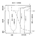
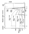
- FIG. 5 shows the clutch hydraulic pressure command output to the inner clutch control valve 27 IN , the actual hydraulic pressure inside the inner steering clutch 40 IN , the rotational speed of the turning motor 80, the peripheral speed of the inner steering clutch 40 IN , and the inner steering clutch 40 IN. The time course of each heat load generated at 40 IN is shown.
- the inner clutch control valve 27 IN is a clutch control valve corresponding to the inner steering clutch 40 IN among the left and right clutch control valves 27L and 27R.
- the peripheral speed of the inner steering clutch 40 IN is the relative rotational speed of the inner steering clutch 40 IN with respect to the inner sun gear 33 IN that is idled by the rotational power from the input shaft 26 .
- the heat load generated in the inner steering clutch 40 IN begins to gradually increase from timing t1 when the inner steering clutch 40 IN begins to partially engage, and after recording the maximum value at timing t3, the inner steering clutch 40 IN is fully engaged. becomes 0 at timing t2.
- the rotation speed of the turning motor 80 is reduced before the timing t1 when the inner steering clutch 40 IN starts to partially engage, so the peripheral speed of the inner steering clutch 40 IN at the timing t1 is high, As a result, the heat load generated in the inner steering clutch 40 IN is increased.
- the inner steering clutch 40 IN is gradually filled with hydraulic fluid after timing t0, and the filling of hydraulic fluid is completed at timing t1. Then, the inner steering clutch 40 IN begins to be partially engaged at timing t1 and fully engaged at timing t2. Therefore, the peripheral speed of the inner steering clutch 40 IN gradually decreases from timing t1 to timing t2, and becomes 0 after timing t2.
- the heat load generated in the inner steering clutch 40 IN begins to gradually increase from timing t1 when the inner steering clutch 40 IN begins to partially engage, and after recording the maximum value at timing t3, the inner steering clutch 40 IN is fully engaged. becomes 0 at timing t2.
- the rotational speed of the turning motor 80 is maintained until the timing t1 when the inner steering clutch 40 IN begins to partially engage, so the peripheral speed of the inner steering clutch 40 IN at the timing t1 is the above-mentioned comparison It is slower than the example, and as a result, the heat load generated on the inner steering clutch 40 IN can be suppressed.
- the rotation speed of the turning motor 80 starts to decrease immediately after the timing t1 at which the inner steering clutch 40 IN starts to partially engage, but this is not the only option. Even if the rotational speed of the turning motor 80 is maintained after the timing t1 at which the inner steering clutch 40 IN begins to partially engage, the effect of suppressing the thermal load can be obtained. Therefore, the controller 100 should maintain the rotational speed of the swing motor 80 until after timing t1.
- the turning motor 80 is stopped after the timing t3 when the heat load generated in the inner steering clutch 40 IN reaches its maximum value. Therefore, compared to the case where the turning motor 80 is stopped before timing t3, the maximum value of the thermal load generated in the inner steering clutch 40 IN can be reduced.
- the controller 100 switches from the gentle turning mode to the pivot turning mode and from the pivot turning mode to the gentle turning mode according to the amount of operation of the steering lever 35.
- the controller 100 may switch from the gentle turn mode to the pivot turn mode in response to the operation amount of the steering lever 35 being greater than the first predetermined amount TH1 and the pivot turn instruction being received from the operator.
- the controller 100 may switch from the pivot turn mode to the gentle turn mode in response to the pivot turn instruction being no longer accepted from the operator during the pivot turn mode.
- FIG. 6 is a schematic system configuration diagram of the power transmission system provided in the bulldozer 1a according to this modified example.
- the bulldozer 1a has the same configuration as the bulldozer 1 according to the above-described embodiment, except that it has a pivot turning button 36. As shown in FIG.
- the pivot turn button 36 is connected to the controller 100.
- a pivot turn button 36 receives a pivot turn instruction from the operator. When the pivot turn button 36 is pressed by the operator, the pivot turn button 36 transmits a pivot turn instruction to the controller 100 .
- the pivot turn button 36 may transmit pivot turn instructions to the controller 100 while it is being pressed by the operator, or may continue to transmit pivot turn instructions to the controller 100 until it is pressed again by the operator.
- the controller 100 sets the running mode of the bulldozer 1 to the straight traveling mode, as described in the above embodiment.
- the controller 100 sets the travel mode of the bulldozer 1 to the pivot turn mode.
- the control of the controller 100 in the pivot turning mode is as described in the above embodiment.
- the control of the controller 100 when switching from the pivot turning mode to the gentle turning mode is as described in the above embodiment.
- the left and right steering brakes 50L and 50R are negative type hydraulic brakes, but may be positive type hydraulic brakes.
- the left and right output shafts 60L, 60R are connected to the left and right sprockets 2L, 2R. may be interposed.
- the rotational speed control of the turning motor 80 is performed both when the pivot turning mode is immediately switched to the straight-ahead mode and when the pivot turning mode is switched to the gentle turning mode.
- the rotational speed control of the turning motor 80 may be performed only in one case.
Landscapes
- Engineering & Computer Science (AREA)
- Mining & Mineral Resources (AREA)
- Civil Engineering (AREA)
- General Engineering & Computer Science (AREA)
- Structural Engineering (AREA)
- Chemical & Material Sciences (AREA)
- Combustion & Propulsion (AREA)
- Transportation (AREA)
- Mechanical Engineering (AREA)
- Automation & Control Theory (AREA)
- Non-Deflectable Wheels, Steering Of Trailers, Or Other Steering (AREA)
- Operation Control Of Excavators (AREA)
Abstract
Description
図1は、履帯式作業機械の一例であるブルドーザ1の斜視図である。図2は、ブルドーザ1の動力伝達系統の断面構成図である。図3は、ブルドーザ1の動力伝達系統の概略システム構成図である。
エンジン動力伝達部20は、エンジン10からの動力を左右の遊星歯車機構30L,30Rに伝達する。エンジン動力伝達部20は、動力取出装置(パワーテイクオフ)21と、トルクコンバータ22と、トランスミッション23と、ピニオン24と、ベベルギア25と、入力軸26とを含む。
左右の遊星歯車機構30L,30Rは、入力軸26と左右の出力軸60L,60Rとの間に配置される。左右の遊星歯車機構30L,30Rは、左右のリングギア31L,31Rと、左右のプラネタリギア32L,32Rと、左右のサンギア33L,33Rと、左右のキャリア34L,34Rとを有する。
左右のステアリングクラッチ40L,40Rは、左右の遊星歯車機構30L,30Rとモータ動力伝達部90との間に配置される。左右のステアリングクラッチ40L,40Rは、左右の遊星歯車機構30L,30Rが有する左右のサンギア33L,33Rとモータ動力伝達部90が有する左右のクラッチギア91L,91Rとを離接させる。
左右のステアリングブレーキ50L,50Rは、作動油の供給によって駆動する。左右のステアリングブレーキ50L,50Rは、係合及び開放可能な湿式多板式クラッチによって構成される。本実施形態において、左右のステアリングブレーキ50L,50Rは、ネガティブタイプの油圧ブレーキである。左右のステアリングブレーキ50L,50Rは、作動油が供給されないとき完全係合し、供給される作動油の油圧が所定値未満であるとき部分係合し、供給される作動油の油圧が所定値以上であるとき開放される。左右のステアリングブレーキ50L,50Rが係合(完全係合又は部分係合)されると、左右のステアリングブレーキ50L,50Rに制動力が生じる。
旋回モータ80は、エンジン10の動力によって駆動する。旋回モータ80は、正回転方向及び反回転方向のいずれかで回転する。旋回モータ80の回転方向及び回転数は、コントローラ100によって制御される。旋回モータ80の回転数は、エンジン10から伝達される動力に応じて0%から100%(最大値)まで変化する。
モータ動力伝達部90は、旋回モータ80と左右のステアリングクラッチ40L,40Rとの間に配置される。モータ動力伝達部90は、旋回モータ80の回転動力を左右のステアリングクラッチ40L,40Rに伝達する。
コントローラ100は、ブルドーザ1を走行させるために、エンジン10の回転数と、トランスミッション23の速度段クラッチ及び方向段クラッチとを制御する。
直進モードにおいて、コントローラ100は、左右のクラッチ用コントロールバルブ27L,27Rを制御して、左右のステアリングクラッチ40L,40Rを完全係合させる。
緩旋回モードにおいて、コントローラ100は、左右のクラッチ用コントロールバルブ27L,27Rを制御して、左右のステアリングクラッチ40L,40Rを係合(典型的には、完全係合)させる。
信地旋回モードにおいて、コントローラ100は、左右のクラッチ用コントロールバルブ27L,27Rを制御して、内側ステアリングクラッチ40INを開放させ、外側ステアリングクラッチ40OUTを係合(典型的には、完全係合)させる。
コントローラ100は、信地旋回モードから直進モード又は緩旋回モードへ切り替える場合、内側ステアリングクラッチ40INを開放状態から係合状態に移行させ、内側ステアリングブレーキ50INを制動状態から開放状態に移行させ、かつ、旋回モータ80の回転数を低減させる。
図5を参照しながら、比較例に係る制御について説明する。
図5を参照しながら、実施例に係る制御について説明する。
本発明は以上のような実施形態に限定されるものではなく、本発明の範囲を逸脱することなく種々の変形又は修正が可能である。
上記実施形態において、コントローラ100は、操向レバー35の操作量に応じて、緩旋回モードから信地旋回モードへの切り替えと、信地旋回モードから緩旋回モードへの切り替えとを行うこととしたが、これに限られない。コントローラ100は、操向レバー35の操作量が第1所定量TH1より大きく、かつ、信地旋回指示をオペレータから受け付けたことに応じて、緩旋回モードから信地旋回モードに切り替えてもよい。さらに、コントローラ100は、信地旋回モード中において、信地旋回指示をオペレータから受け付けなくなったことに応じて、信地旋回モードから緩旋回モードに切り替えてもよい。
上記実施形態において、左右のステアリングクラッチ40L,40Rは、ポジティブタイプの油圧クラッチであることとしたが、ネガティブタイプの油圧クラッチであってもよい。
上記実施形態において、左右のステアリングブレーキ50L,50Rは、ネガティブタイプの油圧ブレーキであることとしたが、ポジティブタイプの油圧ブレーキであってもよい。
上記実施形態において、左右の出力軸60L,60Rは、左右のスプロケット2L,2Rに連結されることとしたが、左右の出力軸60L,60Rと左右のスプロケット2L,2Rとの間には、左右の終減速装置が介在していてもよい。
上記実施形態では、信地旋回モードから直進モードへ即座に切り替える場合と、信地旋回モードから緩旋回モードへ切り替える場合との両方において旋回モータ80の回転数制御を行うこととしたが、いずれか一方の場合にのみ旋回モータ80の回転数制御を行ってもよい。
10 エンジン
20 エンジン動力伝達部
26 入力軸
30L,30R 左右の遊星歯車機構
31L,31R 左右のリングギア
32L,32R 左右のプラネタリギア
33L,33R 左右のサンギア
34L,34R 左右のキャリア
40L,40R 左右のステアリングクラッチ
50L,50R 左右のステアリングブレーキ
60L,60R 左右の出力軸
80 旋回モータ
90 モータ動力伝達部
91L,91R 左右のクラッチギア
92 第1トランスファギア
93 副軸
94 第2トランスファギア
95 アイドラギア
96 ピニオンギア
98 固定部材
99 旋回用モータ
100 コントローラ
Claims (4)
- 入力軸と左右の出力軸との間に配置される左右の遊星歯車機構と、
前記入力軸を中心として回転可能であり、前記左右の遊星歯車機構による前記入力軸から前記左右の出力軸への回転動力の伝達及び遮断を切り替える左右のステアリングクラッチと、
前記左右の出力軸を制動する左右のステアリングブレーキと、
前記左右の出力軸に回転数差が生じるように前記左右のステアリングクラッチを回転させる旋回モータと、
前記左右のステアリングクラッチ、前記左右のステアリングブレーキ及び前記旋回モータを制御することによって、直進モード、緩旋回モード及び信地旋回モードのいずれかで履帯式作業機械を旋回させるコントローラと、
を備え、
前記コントローラは、前記直進モードにおいて、前記左右のステアリングクラッチを係合させ、前記左右のステアリングブレーキを開放させ、かつ、前記旋回モータを停止させ、
前記コントローラは、前記緩旋回モードにおいて、前記左右のステアリングクラッチを係合させ、前記左右のステアリングブレーキを開放させ、かつ、前記旋回モータを駆動させ、
前記コントローラは、前記信地旋回モードにおいて、前記左右のステアリングクラッチのうち前記旋回方向に対応する内側ステアリングクラッチを開放させ、前記左右のステアリングブレーキのうち旋回方向に対応する内側ステアリングブレーキを制動させ、かつ、前記旋回モータを駆動させ、
前記コントローラは、前記信地旋回モードから前記直進モード又は前記緩旋回モードに移行する際、前記内側ステアリングクラッチが部分係合し始める第1タイミング以降まで前記旋回モータの回転数を維持する、
履帯式作業機械。 - 前記コントローラは、前記信地旋回モードから前記直進モード又は前記緩旋回モードに移行する際、前記内側ステアリングクラッチが完全係合する第2タイミング以前に前記旋回モータを停止させる、
請求項1に記載の履帯式作業機械。 - 前記左右の遊星歯車機構それぞれは、
前記入力軸に連結されるリングギアと、
前記入力軸に回転自在に取り付けられ、前記ステアリングクラッチに連結されるサンギアと、
前記リングギア及び前記サンギアの間に配置されるプラネタリギアと、
前記プラネタリギアと前記出力軸に連結されるキャリアと、
を有する、
請求項1又は2に記載の履帯式作業機械。 - 前記左右のステアリングクラッチを介して前記左右の遊星歯車機構それぞれの前記サンギアと離接可能であり、互いに逆方向に回転する左右のクラッチギアと、
前記左右のクラッチギアに前記旋回モータの回転動力を伝達するアイドラギアと、
を備える、
請求項3に記載の履帯式作業機械。
Priority Applications (2)
| Application Number | Priority Date | Filing Date | Title |
|---|---|---|---|
| US18/253,842 US12522293B2 (en) | 2021-01-21 | 2021-12-15 | Crawler-type work machine |
| CN202180072928.9A CN116348362B (zh) | 2021-01-21 | 2021-12-15 | 履带式工程机械 |
Applications Claiming Priority (2)
| Application Number | Priority Date | Filing Date | Title |
|---|---|---|---|
| JP2021008066A JP7429201B2 (ja) | 2021-01-21 | 2021-01-21 | 履帯式作業機械 |
| JP2021-008066 | 2021-01-21 |
Publications (1)
| Publication Number | Publication Date |
|---|---|
| WO2022158179A1 true WO2022158179A1 (ja) | 2022-07-28 |
Family
ID=82548264
Family Applications (1)
| Application Number | Title | Priority Date | Filing Date |
|---|---|---|---|
| PCT/JP2021/046213 Ceased WO2022158179A1 (ja) | 2021-01-21 | 2021-12-15 | 履帯式作業機械 |
Country Status (4)
| Country | Link |
|---|---|
| US (1) | US12522293B2 (ja) |
| JP (1) | JP7429201B2 (ja) |
| CN (1) | CN116348362B (ja) |
| WO (1) | WO2022158179A1 (ja) |
Families Citing this family (1)
| Publication number | Priority date | Publication date | Assignee | Title |
|---|---|---|---|---|
| JP7692264B2 (ja) * | 2020-12-25 | 2025-06-13 | 株式会社小松製作所 | 履帯式作業機械 |
Citations (4)
| Publication number | Priority date | Publication date | Assignee | Title |
|---|---|---|---|---|
| JP2001260928A (ja) * | 2000-03-24 | 2001-09-26 | Komatsu Ltd | 装軌車両の操向方法および操向装置 |
| JP2002293261A (ja) * | 2001-03-29 | 2002-10-09 | Komatsu Ltd | 装軌車両の操向装置 |
| JP2004034724A (ja) * | 2002-06-28 | 2004-02-05 | Kubota Corp | 作業機の走行構造 |
| US20120285765A1 (en) * | 2011-05-09 | 2012-11-15 | Caterpillar Inc. | Continuously variable steering apparatus |
Family Cites Families (10)
| Publication number | Priority date | Publication date | Assignee | Title |
|---|---|---|---|---|
| JPS5327929A (en) | 1976-08-26 | 1978-03-15 | Komatsu Ltd | Steering system for catapillar vehicles |
| JP3256338B2 (ja) | 1993-06-25 | 2002-02-12 | 株式会社小松製作所 | 装軌式車両のギヤード操向装置、およびその制御装置 |
| JP3438929B2 (ja) | 1994-01-26 | 2003-08-18 | 三菱重工業株式会社 | 油圧駆動式装軌車両の変速走行制御装置 |
| CN2585894Y (zh) | 2002-02-04 | 2003-11-12 | 中国人民解放军第六四四三工厂 | 动力转向履带式推土机 |
| JP4632771B2 (ja) * | 2004-02-25 | 2011-02-16 | 株式会社小松製作所 | 油圧操向方式の作業車両 |
| JP5128455B2 (ja) * | 2008-12-18 | 2013-01-23 | 株式会社小松製作所 | 車両の制御装置 |
| JP5205532B1 (ja) | 2012-05-01 | 2013-06-05 | 株式会社小松製作所 | 履帯式作業車両 |
| CN202574365U (zh) | 2012-05-25 | 2012-12-05 | 山推工程机械股份有限公司 | 一种电驱动和液压差速转向组合装置及推土机 |
| CN203639965U (zh) | 2013-10-16 | 2014-06-11 | 天津柳工机械有限公司 | 推土机行走液压装置 |
| KR20170143301A (ko) * | 2016-06-21 | 2017-12-29 | 대동공업주식회사 | 수확기의 트랜스미션 및 이를 포함하는 수확기 |
-
2021
- 2021-01-21 JP JP2021008066A patent/JP7429201B2/ja active Active
- 2021-12-15 CN CN202180072928.9A patent/CN116348362B/zh active Active
- 2021-12-15 WO PCT/JP2021/046213 patent/WO2022158179A1/ja not_active Ceased
- 2021-12-15 US US18/253,842 patent/US12522293B2/en active Active
Patent Citations (4)
| Publication number | Priority date | Publication date | Assignee | Title |
|---|---|---|---|---|
| JP2001260928A (ja) * | 2000-03-24 | 2001-09-26 | Komatsu Ltd | 装軌車両の操向方法および操向装置 |
| JP2002293261A (ja) * | 2001-03-29 | 2002-10-09 | Komatsu Ltd | 装軌車両の操向装置 |
| JP2004034724A (ja) * | 2002-06-28 | 2004-02-05 | Kubota Corp | 作業機の走行構造 |
| US20120285765A1 (en) * | 2011-05-09 | 2012-11-15 | Caterpillar Inc. | Continuously variable steering apparatus |
Also Published As
| Publication number | Publication date |
|---|---|
| US20240101192A1 (en) | 2024-03-28 |
| CN116348362B (zh) | 2025-10-31 |
| JP2022112296A (ja) | 2022-08-02 |
| CN116348362A (zh) | 2023-06-27 |
| US12522293B2 (en) | 2026-01-13 |
| JP7429201B2 (ja) | 2024-02-07 |
Similar Documents
| Publication | Publication Date | Title |
|---|---|---|
| JP7478678B2 (ja) | 履帯式作業機械 | |
| JPWO2004104449A1 (ja) | 変速装置 | |
| JP7643868B2 (ja) | 履帯式作業機械 | |
| WO2023149141A1 (ja) | 履帯式作業機械 | |
| CN113404850B (zh) | 具有原位转向和单侧制动转向的双模式变速箱 | |
| JP7429201B2 (ja) | 履帯式作業機械 | |
| JP4834797B2 (ja) | 動力伝達装置 | |
| JP7692264B2 (ja) | 履帯式作業機械 | |
| JP7612694B2 (ja) | 履帯式作業機械 | |
| JP7828281B2 (ja) | 履帯式作業機械 | |
| WO2023157490A1 (ja) | 作業機械 | |
| JP2721084B2 (ja) | 作業車の走行伝動構造 | |
| JP3097632B2 (ja) | 作業車輌の走行伝動装置 | |
| KR920002210Y1 (ko) | 무한궤도 차량의 조향케이스 구조 | |
| JP2004034724A (ja) | 作業機の走行構造 | |
| JPH0813660B2 (ja) | 移動農機の走行動力伝達装置 | |
| JPH10119812A (ja) | 作業車輌の走行伝動装置 | |
| JP2650388C (ja) | ||
| JP2004074999A (ja) | 走行装置の伝動機構 |
Legal Events
| Date | Code | Title | Description |
|---|---|---|---|
| 121 | Ep: the epo has been informed by wipo that ep was designated in this application |
Ref document number: 21921281 Country of ref document: EP Kind code of ref document: A1 |
|
| WWE | Wipo information: entry into national phase |
Ref document number: 18253842 Country of ref document: US |
|
| NENP | Non-entry into the national phase |
Ref country code: DE |
|
| 122 | Ep: pct application non-entry in european phase |
Ref document number: 21921281 Country of ref document: EP Kind code of ref document: A1 |
|
| WWG | Wipo information: grant in national office |
Ref document number: 202180072928.9 Country of ref document: CN |
|
| WWG | Wipo information: grant in national office |
Ref document number: 18253842 Country of ref document: US |