WO2022130540A1 - 水切り部材 - Google Patents
水切り部材 Download PDFInfo
- Publication number
- WO2022130540A1 WO2022130540A1 PCT/JP2020/046992 JP2020046992W WO2022130540A1 WO 2022130540 A1 WO2022130540 A1 WO 2022130540A1 JP 2020046992 W JP2020046992 W JP 2020046992W WO 2022130540 A1 WO2022130540 A1 WO 2022130540A1
- Authority
- WO
- WIPO (PCT)
- Prior art keywords
- draining member
- draining
- drainer
- main surface
- coupling
- Prior art date
Links
- 230000008878 coupling Effects 0.000 claims abstract description 55
- 238000010168 coupling process Methods 0.000 claims abstract description 55
- 238000005859 coupling reaction Methods 0.000 claims abstract description 55
- 239000000853 adhesive Substances 0.000 claims description 7
- 230000001070 adhesive effect Effects 0.000 claims description 7
- 229910052782 aluminium Inorganic materials 0.000 claims description 6
- XAGFODPZIPBFFR-UHFFFAOYSA-N aluminium Chemical compound [Al] XAGFODPZIPBFFR-UHFFFAOYSA-N 0.000 claims description 6
- 239000000463 material Substances 0.000 description 5
- XLYOFNOQVPJJNP-UHFFFAOYSA-N water Substances O XLYOFNOQVPJJNP-UHFFFAOYSA-N 0.000 description 5
- 229910052751 metal Inorganic materials 0.000 description 4
- 239000002184 metal Substances 0.000 description 4
- 238000009423 ventilation Methods 0.000 description 4
- 230000000694 effects Effects 0.000 description 3
- 230000004048 modification Effects 0.000 description 3
- 238000012986 modification Methods 0.000 description 3
- 238000000034 method Methods 0.000 description 2
- 229910000838 Al alloy Inorganic materials 0.000 description 1
- 238000010276 construction Methods 0.000 description 1
- 238000000465 moulding Methods 0.000 description 1
- 238000007789 sealing Methods 0.000 description 1
Images


Classifications
-
- E—FIXED CONSTRUCTIONS
- E04—BUILDING
- E04B—GENERAL BUILDING CONSTRUCTIONS; WALLS, e.g. PARTITIONS; ROOFS; FLOORS; CEILINGS; INSULATION OR OTHER PROTECTION OF BUILDINGS
- E04B1/00—Constructions in general; Structures which are not restricted either to walls, e.g. partitions, or floors or ceilings or roofs
- E04B1/62—Insulation or other protection; Elements or use of specified material therefor
- E04B1/64—Insulation or other protection; Elements or use of specified material therefor for making damp-proof; Protection against corrosion
-
- E—FIXED CONSTRUCTIONS
- E04—BUILDING
- E04D—ROOF COVERINGS; SKY-LIGHTS; GUTTERS; ROOF-WORKING TOOLS
- E04D13/00—Special arrangements or devices in connection with roof coverings; Protection against birds; Roof drainage ; Sky-lights
- E04D13/15—Trimming strips; Edge strips; Fascias; Expansion joints for roofs
- E04D13/158—Trimming strips; Edge strips; Fascias; Expansion joints for roofs covering the overhang at the eave side, e.g. soffits, or the verge of saddle roofs
Definitions
- This disclosure relates to a drainer member placed on the exterior of a building.
- Patent Document 1 discloses an example of a configuration including a draining portion.
- the draining section described in the same document suppresses the intrusion of water into the molding.
- a drainer may be provided on the exterior part provided on the outer surface of the building.
- a drainer is provided along the lower surface of the exterior portion of the structure overhanging from the outer wall of the building.
- Examples of structures include balconies, balconies, bay windows, roof eaves, and the like.
- the drainer provided on the exterior portion of such a structure may include a plurality of drainer members.
- the plurality of draining members are arranged on the exterior portion so that a step does not occur between the adjacent draining members. However, it is not easy to arrange the draining members so that a step does not occur between the adjacent draining members.
- the draining member that solves the above problems is a draining member arranged at the lower part of the exterior portion of the building, and the draining member is a joint portion for connecting to a draining member different from the draining member. To prepare for. According to the draining member, since the joint portion for connecting the draining member and another draining member is provided, the plurality of draining members can be easily positioned when the plurality of draining members are arranged at the lower part of the exterior portion.
- the connecting portion includes a holding portion for holding a connecting member for connecting the draining member, and the holding portion of the draining member and the other draining member. By holding the coupling member with the holding portion, the draining member and the other draining member are coupled. According to the draining member, when the plurality of draining members are arranged at the lower part of the exterior portion, the plurality of draining members can be easily positioned.
- the draining member includes a first draining member and a second draining member different from the first draining member, and the first draining member is at least a first coupling.
- the second draining member has at least a second coupling portion, and the first coupling portion provided on the first draining member can be coupled to the second coupling portion provided on the second draining member.
- the second coupling portion which is configured in the above or is provided in the second draining member, is configured to be connectable with the first coupling portion provided in the first draining member. According to the draining member, when the plurality of draining members are arranged at the lower part of the exterior portion, the plurality of draining members can be easily positioned.
- the draining member is made of aluminum. According to the draining member, the draining member can be easily cut when adjusting the length of the draining member.
- the draining member according to the present disclosure when a plurality of draining members are arranged at the lower part of the exterior portion, the plurality of draining members can be easily positioned.
- FIG. 2 is a partially enlarged view of the R1 region of FIG.
- FIG. 4 is a cross-sectional view of the draining member of FIG.
- FIG. 3 is a perspective view of a drainer showing a state in which the drainer members of the first embodiment are connected.
- the perspective view of the drainer which shows the state before the drainer member of 2nd Embodiment is combined.
- FIG. 3 is a perspective view of a drainer showing a state in which the drainer members of the second embodiment are connected.
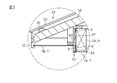
- the drainer 10 of the first embodiment will be described with reference to FIGS. 1 to 7.
- the drainer 10 is provided in the building 1.
- the drainer 10 of the present embodiment is arranged at the lower part of the exterior portion 8 in order to suppress the rainwater flowing through the exterior portion 8 from being transmitted to the lower surface of the exterior portion 8.
- the building 1 is, for example, a house including the building main body 2.
- the building main body 2 includes a roof 2A and an outer wall 3.
- the roof surface 2B of the roof 2A is parallel to or inclined with respect to the horizontal direction.
- Building 1 further comprises an outdoor living 4. Examples of outdoor living 4 include terraces, balconies, and balconies.
- the roof 2A is formed on a plurality of horizontally arranged horizontal lumbers 5A, rafters 5B directly or indirectly supported by the plurality of horizontal lumbers 5A, and rafters 5B. It includes a receiving material 5C provided and a roof base portion 5D supported by the receiving material 5C. A roofing material is stretched on the roof base portion 5D.
- the roof 2A overhangs the outer wall 3 so as to cover the outdoor living 4.
- outdoor living 4 examples include terraces, balconies, and balconies.
- one or more horizontal members 5A are arranged on the outdoor living 4.
- the horizontal member 5A (hereinafter, referred to as "outer horizontal member 6") is arranged on the outdoor living 4.
- the portion of the outdoor living 4 facing the floor surface is closed by the cover member 7.
- the space between the outer horizontal member 6 and the outer wall 3 is closed by the first cover member 7A.
- the first cover member 7A is arranged so as to cover the lower surface 6A of the outer horizontal member 6.
- the space between the side surface 6B of the outer horizontal member 6 and the eaves edge member 2C is closed by the second cover member 7B.
- the second cover member 7B is arranged at a higher position than the first cover member 7A. Specifically, the second cover member 7B is arranged so that the lower surface of the second cover member 7B intersects the side surface 6B of the outer horizontal member 6. The lower portion of the side surface 6B of the outer horizontal member 6 is located below the second cover member 7B. The side surface of the outer horizontal member 6 is covered with the exterior portion 8.
- the exterior portion 8 is preferably formed of a finishing material having waterproof and light resistance. Examples of finishing materials include siding and tiles.
- the exterior portion 8 is attached to the outer horizontal member 6 via the furring strip 9.
- a ventilation passage VP through which air passes is provided between the exterior portion 8 and the outer horizontal member 6.
- a drainer 10 is arranged at the bottom of the exterior portion 8.
- the drainer 10 suppresses the rainwater attached to the exterior portion 8 from being transmitted to the outer horizontal member 6 via the lower surface of the exterior portion 8. Further, the drainer overhangs the outdoor living 4 by hiding the lower surface of the exterior portion 8 and improves the design of the lower surface of the roof 2A.
- the main element constituting the drainer 10 is the drainer member 11.
- the draining member 11 includes a mounting portion 12 for attaching the draining member 11 to the building 1 and a guide portion 13 for guiding water.
- the drainer member 11 is formed of, for example, metal.
- the metal for example, a metal that can be easily processed at a construction site is used.
- the metal forming the drainer member 11 is aluminum or an aluminum alloy.
- the draining member 11 is fixed to the outer horizontal member 6 by fixing the mounting portion 12 to the outer horizontal member 6 with screws. Specifically, in a state where the draining member 11 is arranged at the lower part of the exterior portion 8, the mounting portion 12 is arranged in the ventilation passage VP between the exterior portion 8 and the outer horizontal member 6.
- the main body of the mounting portion 12 includes a first main surface 12A and a second main surface 12B.
- the shape of the main body of the mounting portion 12 is formed, for example, in the shape of a plate.
- the first main surface 12A is a surface in which the draining member 11 is arranged at the lower part of the exterior portion 8 and at least a part thereof faces the exterior portion 8.
- the second main surface 12B is a surface in which the draining member 11 is arranged at the lower part of the exterior portion 8 and at least a part thereof faces the outer horizontal member 6.
- the guide portion 13 is arranged at a distance from the lower surface of the exterior portion 8 in a state where the draining member 11 is arranged at the lower part of the exterior portion 8.
- the main body of the guide portion 13 includes a first main surface 13A and a second main surface 13B.
- the main body of the guide portion 13 is formed in a plate shape, for example.
- the first main surface 13A of the guide portion 13 is formed continuously with the first main surface 12A of the mounting portion 12.
- the second main surface 13B of the guide portion 13 is formed continuously with the second main surface 12B of the mounting portion 12.
- the angle ⁇ formed by the first main surface 12A and the first main surface 13A is preferably 90 ° or more.
- the angle ⁇ formed by the first main surface 12A and the first main surface 13A is preferably 120 ° or less.
- the drainer member 11 further includes an extension portion 14.
- the extension portion 14 is formed continuously with the guide portion 13.
- the extension portion 14 is formed so as to prevent water flowing through the first main surface 13A of the guide portion 13 from flowing to the second main surface 13B of the guide portion 13.
- the mounting portion 12 is provided at one end in the width direction, and the extension portion 14 is provided at the other end.
- the extension portion 14 is configured to extend downward from the end portion of the guide portion 13 opposite to the portion where the mounting portion 12 is provided in a state where the draining member 11 is arranged below the exterior portion 8.
- the drainer member 11 includes a joint portion 20.
- the connecting portion 20 is configured to connect the draining member 11 and another draining member 111.
- Another draining member 111 has the same configuration as the draining member 11.
- the connecting portion 20 is provided at least on the first main surface 13A of the guide portion 13.
- the coupling portion 20 is further provided on the first main surface 12A of the mounting portion 12.
- the connecting portion 20 includes a holding portion 21 for holding the connecting member 30.
- the holding portion 21 is in a state where the draining member 11 and another draining member 111 are coupled to each other via the coupling member 30, and the second main surface 13B of the guide portion 13 of the draining member 11 and the guide portion 113 of another draining member 111 are connected. It is configured so that it is flush with the second main surface 113B of.
- the holding portion 21 includes a first protrusion 22 protruding from the first main surface 13A of the guide portion 13 and a second protrusion 23 protruding from the first main surface 12A of the mounting portion 12.
- the first protrusion 22 extends along the longitudinal direction XA of the guide portion 13.
- the second protrusion 23 extends along the longitudinal direction XA of the mounting portion 12.
- the first protrusion 22 is composed of a main body portion 22A protruding from the first main surface 13A and a movement restricting portion 22B provided so as to be orthogonal to the longitudinal direction XA of the main body portion 22A.
- the movement control unit 22B is configured in parallel with the first main surface 13A.
- the second protrusion 23 is configured to be parallel to the first main surface 13A.
- the first main surface 13A, the first protrusion 22, and the second protrusion 23 form a holding space S for holding the connecting member 30.
- the draining member 11 and other parts are held by holding a part of the coupling member 30 in the holding space S of the draining member 11 and holding the other part of the coupling member 30 in the holding space S of the other draining member 111. It is coupled with the draining member 111.
- the coupling member 30 includes a main body portion 31.
- the main body portion 31 is formed as a plate-shaped member including the first main surface 31A and the second main surface 31B.
- One of the first main surface 31A and the second main surface 31B comes into contact with the movement restricting portion 22B and the second protrusion 23 of the first protrusion 22 at the time of coupling.
- the other of the first main surface 31A and the second main surface 31B comes into contact with the first main surface 13A at the time of joining.
- the size of the main body 31 is set according to the holding space S.
- a method of attaching the drainer 10 of the present embodiment will be described with reference to FIGS. 6 and 7.
- the operator brings the mounting portion 12 of the draining member 11 into contact with the side surface 6B of the outer horizontal member 6 and fixes the mounting portion 12 to the outer horizontal member 6 with screws.
- a drainer member 111 different from the drainer member 11 is coupled. In this way, the length of the longitudinal direction XA is extended.
- a part of the connecting member 30 is inserted into the holding space S formed by the first main surface 13A, the first protrusion 22, and the second protrusion 23 of the draining member 11.
- the portion of the coupling member 30 protruding from the holding portion 21 is inserted into the holding space S formed in another draining member 111. It is preferable to apply the adhesive 40 to the first main surface 31A or the second main surface 31B of the coupling member 30 that comes into contact with the first main surface 13A of the guide portion 13. In a state where the draining member 11 and another draining member 111 are coupled via the coupling member 30, the second main surface 13B of the guide portion 13 of the draining member 11 and the second main surface of the guide portion 113 of another draining member 111. It is flush with 113B.
- first main surface 12A of the mounting portion 12 and the first main surface 112A of the mounting portion 112 of another draining member 111 are flush with each other.
- the mounting portion 112 of another draining member 111 is fixed to the side surface 6B of the outer horizontal member 6 with a screw.
- the length of the drainer 10 composed of the drainer member 11 and another drainer member 111 in the longitudinal direction XA does not match the length in the horizontal direction of the exterior portion 8, the length is adjusted by the following means.
- another drainer member 111 is combined to form the longitudinal XA. Extend the length.
- the drainer 11 or another drainer may be used with an electric saw. Cut a part of 111.
- the length of the drainer 10 in the longitudinal direction XA is made to match the length of the exterior portion 8 in the horizontal direction.
- the operation of the drainer 10 of the present embodiment will be described.
- the rainwater that has come into contact with the exterior portion 8 due to a strong wind or the like comes into contact with the first main surface 13A of the guide portion 13 and falls downward along the extension portion 14.
- the configuration of the guide portion 13 and the extension portion 14 prevents rainwater that has come into contact with the exterior portion 8 from coming into contact with the outer horizontal member 6. Further, by arranging the guide portion 13 of the drainer 10 below the lower end opening of the ventilation passage VP, it is possible to prevent rainwater from reaching the inside of the ventilation passage VP.
- the draining member 11 is arranged at the lower part of the exterior portion 8 of the building 1.
- the draining member 11 includes a connecting portion 20 for connecting to a draining member 111 different from the draining member 11.
- the joint portion 20 for connecting the drainer member 11 and another drainer member 111 is provided, when the drainer member 11 and the drainer member 111 are arranged at the lower part of the exterior portion 8, the drainer member 11 is drained.
- One of the member 11 and the drainer member 111 can be easily positioned with respect to the other.
- the connecting portion 20 includes a holding portion 21 that holds a connecting member 30 for connecting the draining member 11.
- the holding portion 21 of the draining member 11 and the holding portion of another draining member 111 hold the coupling member 30, so that the draining member 11 and another draining member 111 are coupled.
- the drainer 10 of the present embodiment when the drainer member 11 and the drainer member 111 are arranged at the lower part of the exterior portion 8, one of the drainer member 11 and another drainer member 111 can be easily positioned with respect to the other.
- the bonding member 30 and the bonding portion 20 are bonded with an adhesive 40.
- the coupling force of the coupling member 30 can be improved.
- the adhesive 40 has a sealing action, the gap formed between the connecting member 30 and the connecting portion 20 is sealed, so that rainwater in contact with the first main surface 13A of the guide portion 13 is sealed. However, the flow from the gap to the second main surface 13B is suppressed.
- the drainer member 11 is made of aluminum. According to the drainer 10 of the present embodiment, the drainer member 11 is made of aluminum. When the draining member 11 and another draining member 111 are connected, the length of the draining member connected to each other in the longitudinal direction XA may be longer than the horizontal length of the exterior portion 8. In this case, the appearance and the effect of draining may be deteriorated. Since the draining member 11 is made of aluminum, it can be easily cut.
- the drainer 100 of the second embodiment will be described with reference to FIGS. 8 and 9.
- the drainer 100 of the second embodiment is composed of the first drainer member 211 and the second drainer member 311.
- the same components as those of the draining member 11 of the first embodiment are designated by the same reference numerals, and some or all of the description thereof may be omitted.
- the first draining member 211 includes at least one of the first coupling portion 20A and the second coupling portion 20B.
- the second draining member 311 includes at least the other of the first coupling portion 20A and the second coupling portion 20B.
- the first draining member 211 includes a first coupling portion 20A
- the second draining member 311 includes a second coupling portion 20B.
- the first coupling portion 20A and the second coupling portion 20B are configured to be connectable.
- the first joint portion 20A is provided on the third main surface 213C of the guide portion 213.
- the third main surface 213C is a surface connecting the first main surface 213A and the second main surface 213B of the first draining member 211 at the end portion of the first draining member 211 in the longitudinal direction XA.
- the first coupling portion 20A is configured to have a convex shape protruding from the third main surface 213C.
- the second joint portion 20B is provided on the third main surface 313C.
- the third main surface 313C is a surface connecting the first main surface 313A and the second main surface 313B of the second draining member 311 at the end portion of the second draining member 311 in the longitudinal direction XA.
- the second joint portion 20B is formed in a concave shape recessed from the third main surface 313C.
- the first drainer member 211 and the second drainer member 311 are connected, for example, the first joint portion of the first drainer member 211 is connected to the second joint portion 20B of the second drainer member 311.
- the first drainer member 211 is moved so that 20A is coupled.
- the adhesive 40 may be applied to at least one of the first coupling portion 20A and the second coupling portion 20B.
- FIG. 9 in a state where the first draining member 211 and the second draining member 311 are coupled, the first coupling portion 20A and the second coupling portion 20B are mounted with the first main surface 212A of the mounting portion 212.
- the first main surface 312A of the unit 312 is configured to be flush with each other.
- the first coupling portion 20A and the second coupling portion 20B are the second main surface 213B of the guide portion 213 and the second main surface 313B of the guide portion 313. Is configured to be flush with each other.
- the first coupling portion 20A and the second coupling portion 20B are the first main surface 213A of the guide portion 213 and the first main surface of the guide portion 313. It is configured so that the surface 313A and the surface 313A are flush with each other.
- the drainer 100 includes a first drainer member 211 and a second drainer member 311 separate from the first drainer member 211.
- the first draining member 211 has at least the first coupling portion 20A
- the second draining member 311 has at least the second coupling portion 20B.
- the first coupling portion 20A provided in the first draining member 211 is configured to be able to be coupled to the second coupling portion 20B provided in the second draining member 311 or is provided in the second draining member 311. Is configured to be able to be coupled to the first coupling portion 20A provided on the first draining member 211.
- the drainer 100 of the present embodiment when the first drainer member 211 and the second drainer member 311 are arranged at the lower part of the exterior portion 8, one of the first drainer member 211 and the second drainer member 311 is opposed to the other. Easy positioning.
- the first coupling portion 20A of the present embodiment is provided on the third main surface 213C.
- the second coupling portion 20B is provided on the third main surface 313C. Since the bonding portion 20 is not formed on the first main surface 213A and the first main surface 313A, the first main surface 213A and the first main surface 313A can be configured to be flush with each other at the time of bonding. When the first main surface 213A and the first main surface 313A are configured to be flush with each other in a state where the first draining member 211 and the second draining member 311 are connected, the first main surface 213A and the first main surface 213A are configured to be flush with each other.
- the description of the embodiment is an example of a possible form of the draining member according to the present invention, and is not intended to limit the form.
- the draining member according to the present invention may take, for example, a modification of each embodiment shown below and a combination of at least two modifications that do not contradict each other.
- the second protrusion 23 may be formed on the first main surface 13A of the guide portion 13.
- the second protrusion 23 includes a main body portion and a movement restricting portion in the same manner as the first protrusion 22.
- the first draining member 211 of the second embodiment has a first coupling portion 20A formed on a third main surface 213C configured at one end of the longitudinal direction XA, and is configured at the other end of the longitudinal direction XA.
- the second coupling portion 20B may be formed on the third main surface 213C. Since the first coupling portion 20A and the second coupling portion 20B are provided on one first draining member 211, a plurality of draining members can be easily connected to each other when extending in the longitudinal direction XA.
- the object to which the drainer 10 is provided is not limited to the example of this embodiment.
- the drainer 10 may be arranged at the lower part of the exterior portion of the vertical wall of the balcony.
- the drainer 10 may be arranged at the lower part of the exterior portion of the wall of the bay window.
- the drainer may be arranged at the lower part of the exterior portion of the hanging wall so as to protrude from the outer wall of the building 1.
Landscapes
- Engineering & Computer Science (AREA)
- Architecture (AREA)
- Civil Engineering (AREA)
- Structural Engineering (AREA)
- Physics & Mathematics (AREA)
- Electromagnetism (AREA)
- Building Environments (AREA)
Abstract
Description
上記水切り部材によれば、水切り部材と別の水切り部材とを結合する結合部を備えるため、複数の水切り部材を外装部の下部に配置する場合に複数の水切り部材を容易に位置決めできる。
上記水切り部材によれば、複数の水切り部材を外装部の下部に配置する場合に複数の水切り部材を容易に位置決めできる。
上記水切り部材によれば、結合部材の結合力を向上させることができる。
上記水切り部材によれば、複数の水切り部材において段差が生じていないため意匠性が向上する。
上記水切り部材によれば、複数の水切り部材を外装部の下部に配置する場合に複数の水切り部材を容易に位置決めできる。
上記水切り部材によれば、水切りの長さ調整の際に水切り部材を容易に切断加工できる。
図1~図7を参照して、第1実施形態の水切り10について説明する。水切り10は、建築物1に設けられる。本実施形態の水切り10は、外装部8に流れる雨水が、外装部8の下面に伝わることを抑制するために、外装部8の下部に配置される。
作業者は、水切り部材11の取付部12を外側横架材6の側面6Bに接触させて、ビスで取付部12を外側横架材6に固定する。1つの水切り部材11で構成される水切り10の長手方向XAの長さが外装部8の水平方向の長さよりも短い場合、水切り部材11とは別の水切り部材111を結合する。このように、長手方向XAの長さを延伸する。具体的には、水切り部材11の第1主面13A、第1突起22、および、第2突起23により形成される保持空間S内に結合部材30の一部を挿入する。結合部材30の他の部分は、水切り部材11から突出する。結合部材30において保持部21から突出した部分は、別の水切り部材111に形成される保持空間S内に挿入される。案内部13の第1主面13Aと接触する結合部材30の第1主面31Aまたは第2主面31Bには、接着剤40を塗布することが好ましい。結合部材30を介して水切り部材11と別の水切り部材111とが結合した状態において、水切り部材11の案内部13の第2主面13Bと別の水切り部材111の案内部113の第2主面113Bとは、面一になる。さらに、取付部12の第1主面12Aと別の水切り部材111の取付部112の第1主面112Aとが面一となる。別の水切り部材111の取付部112は、ビスで外側横架材6の側面6Bに固定する。
強風による吹き込みなどにより、外装部8に接触した雨水は、案内部13の第1主面13Aに接触し、延長部14を伝って下方に落下する。案内部13および延長部14の構成により、外装部8に接触した雨水が外側横架材6に接触することが抑制される。また、水切り10の案内部13が通気通路VPの下端開口の下部に配置されることによって、雨水が通気通路VP内に到達することが抑制される。
(1)水切り部材11は、建築物1の外装部8の下部に配置される。水切り部材11は、水切り部材11とは別の水切り部材111と結合するための結合部20を備える。
本実施形態の水切り10によれば、水切り部材11と別の水切り部材111とを結合する結合部20を備えるため、水切り部材11および水切り部材111を外装部8の下部に配置する場合に、水切り部材11および水切り部材111の一方を他方に対して容易に位置決めできる。
本実施形態の水切り10によれば、水切り部材11および水切り部材111を外装部8の下部に配置する場合に、水切り部材11および別の水切り部材111の一方を他方に対して容易に位置決めできる。
本実施形態の水切り10によれば、結合部材30の結合力を向上させることができる。また、接着剤40がシーリング作用を有している場合、結合部材30と結合部20との間に生じている隙間がシーリングされているため、案内部13の第1主面13Aに接触した雨水が、隙間から第2主面13Bに流れることが抑制される。
本実施形態の水切り10によれば、水切り部材11と別の水切り部材111との間において段差が生じていないため意匠性が向上する。
本実施形態の水切り10によれば、水切り部材11がアルミニウムで構成される。水切り部材11と別の水切り部材111とを結合した場合に、外装部8の水平方向の長さよりも互いに結合した水切り部材の長手方向XAの長さが長くなる場合がある。この場合、外観および水切りの作用が低下する恐れがある。水切り部材11は、アルミニウムで構成されているため、容易に切断加工できる。
図8および図9を参照して、第2実施形態の水切り100について説明する。第2実施形態の水切り100は、第1水切り部材211および第2水切り部材311で構成される。第1実施形態の水切り部材11と同様の構成に関しては、同様の符号を付し、説明の一部または全部を省略する場合がある。
(6)水切り100は、第1水切り部材211と第1水切り部材211とは別の第2水切り部材311とを含む。第1水切り部材211は、少なくとも第1結合部20Aを有し、第2水切り部材311は、少なくとも第2結合部20Bを有する。第1水切り部材211に設けられる第1結合部20Aは、第2水切り部材311に設けられる第2結合部20Bと結合可能に構成され、または、第2水切り部材311に設けられる第2結合部20Bは、第1水切り部材211に設けられる第1結合部20Aと結合可能に構成される。
実施の形態に関する説明は本発明に従う水切り部材が取り得る形態の例示であり、その形態を制限することを意図していない。本発明に従う水切り部材は各実施形態以外に例えば以下に示される各実施形態の変形例、および、相互に矛盾しない少なくとも2つの変形例が組み合わせられた形態を取り得る。
8 …外装部
10 …水切り
11 …水切り部材
20 …結合部
20A…第1結合部
20B…第2結合部
21 …保持部
30 …結合部材
40 …接着剤
111…別の水切り部材
211…第1水切り部材
311…第2水切り部材
Claims (6)
- 建築物の外装部の下部に配置される水切り部材であって、
前記水切り部材は、前記水切り部材とは別の水切り部材と結合するための結合部を備える
水切り部材。 - 前記結合部は、前記水切り部材を結合するための結合部材を保持する保持部を含み、
前記水切り部材の前記保持部と前記別の水切り部材の前記保持部とが前記結合部材を保持することにより、前記水切り部材と前記別の水切り部材とが結合される
請求項1に記載の水切り部材。 - 前記結合部材と前記結合部とは、接着剤で接着される
請求項2に記載の水切り部材。 - 前記水切り部材と前記別の水切り部材とが結合した状態において、前記水切り部材の所定面と前記別の水切り部材の所定面とが面一に構成される
請求項1~3のいずれか一項に記載の水切り部材。 - 前記水切り部材は、第1水切り部材と前記第1水切り部材とは別の第2水切り部材とを含み、
前記第1水切り部材は、少なくとも第1結合部を有し、
前記第2水切り部材は、少なくとも第2結合部を有し、
前記第1水切り部材に設けられる第1結合部は、前記第2水切り部材に設けられる第2結合部と結合可能に構成され、または、前記第2水切り部材に設けられる第2結合部は、前記第1水切り部材に設けられる第1結合部と結合可能に構成される
請求項1に記載の水切り部材。 - 前記水切り部材は、アルミニウムで構成される
請求項1から5のいずれか一項に記載の水切り部材。
Priority Applications (4)
| Application Number | Priority Date | Filing Date | Title |
|---|---|---|---|
| AU2020474030A AU2020474030B2 (en) | 2020-12-16 | 2020-12-16 | Flashing member |
| GB2214759.9A GB2608562A (en) | 2020-12-16 | 2020-12-16 | Draining member |
| JP2022569399A JP7380913B2 (ja) | 2020-12-16 | 2020-12-16 | 水切り部材 |
| PCT/JP2020/046992 WO2022130540A1 (ja) | 2020-12-16 | 2020-12-16 | 水切り部材 |
Applications Claiming Priority (1)
| Application Number | Priority Date | Filing Date | Title |
|---|---|---|---|
| PCT/JP2020/046992 WO2022130540A1 (ja) | 2020-12-16 | 2020-12-16 | 水切り部材 |
Publications (1)
| Publication Number | Publication Date |
|---|---|
| WO2022130540A1 true WO2022130540A1 (ja) | 2022-06-23 |
Family
ID=82059195
Family Applications (1)
| Application Number | Title | Priority Date | Filing Date |
|---|---|---|---|
| PCT/JP2020/046992 WO2022130540A1 (ja) | 2020-12-16 | 2020-12-16 | 水切り部材 |
Country Status (4)
| Country | Link |
|---|---|
| JP (1) | JP7380913B2 (ja) |
| AU (1) | AU2020474030B2 (ja) |
| GB (1) | GB2608562A (ja) |
| WO (1) | WO2022130540A1 (ja) |
Citations (3)
| Publication number | Priority date | Publication date | Assignee | Title |
|---|---|---|---|---|
| JPS6336092Y2 (ja) * | 1982-07-16 | 1988-09-26 | ||
| JPH0335765Y2 (ja) * | 1984-10-15 | 1991-07-30 | ||
| JP2002276043A (ja) * | 2001-03-19 | 2002-09-25 | Asahi Glass Co Ltd | 水切り材 |
Family Cites Families (6)
| Publication number | Priority date | Publication date | Assignee | Title |
|---|---|---|---|---|
| JPS6336092A (ja) * | 1986-07-29 | 1988-02-16 | Matsushita Electric Ind Co Ltd | 密閉型回転圧縮機 |
| JP2673262B2 (ja) * | 1989-06-30 | 1997-11-05 | 雪印乳業株式会社 | クエン酸及びカルシウムが共存する果汁含有カプセル化ゼリーの製法 |
| JPH0726670A (ja) * | 1993-07-14 | 1995-01-27 | Ig Tech Res Inc | 防水継手材 |
| JP2000064518A (ja) * | 1998-08-18 | 2000-02-29 | Ig Tech Res Inc | 防水継手材 |
| US8695293B2 (en) * | 2003-08-22 | 2014-04-15 | Mishko Teodorovich | Door and window sill pan flashing with extension coupler |
| PL223391B1 (pl) * | 2010-10-29 | 2016-10-31 | Fakro Pp Spółka Z Ograniczoną Odpowiedzialnością | Kołnierz uszczelniający połączenie pokrycia dachowego z konstrukcją przenikającą przez dach wyposażony w zatrzaskowe połączenie elementów kołnierza |
-
2020
- 2020-12-16 JP JP2022569399A patent/JP7380913B2/ja active Active
- 2020-12-16 GB GB2214759.9A patent/GB2608562A/en active Pending
- 2020-12-16 AU AU2020474030A patent/AU2020474030B2/en active Active
- 2020-12-16 WO PCT/JP2020/046992 patent/WO2022130540A1/ja active Application Filing
Patent Citations (3)
| Publication number | Priority date | Publication date | Assignee | Title |
|---|---|---|---|---|
| JPS6336092Y2 (ja) * | 1982-07-16 | 1988-09-26 | ||
| JPH0335765Y2 (ja) * | 1984-10-15 | 1991-07-30 | ||
| JP2002276043A (ja) * | 2001-03-19 | 2002-09-25 | Asahi Glass Co Ltd | 水切り材 |
Also Published As
| Publication number | Publication date |
|---|---|
| AU2020474030B2 (en) | 2024-01-04 |
| JP7380913B2 (ja) | 2023-11-15 |
| GB202214759D0 (en) | 2022-11-23 |
| JPWO2022130540A1 (ja) | 2022-06-23 |
| AU2020474030A1 (en) | 2022-06-30 |
| GB2608562A (en) | 2023-01-04 |
Similar Documents
| Publication | Publication Date | Title |
|---|---|---|
| JP5393135B2 (ja) | 軒先構造 | |
| JP5243207B2 (ja) | 庇構造 | |
| WO2022130540A1 (ja) | 水切り部材 | |
| JP4644116B2 (ja) | バルコニーの軒天見切構造 | |
| JP6367682B2 (ja) | 屋根の換気構造及び換気部材 | |
| US20230235622A1 (en) | Building structure | |
| JP4183085B2 (ja) | 換気機能付き軒先構造 | |
| JP6468627B2 (ja) | 軒先換気構造 | |
| JP5775035B2 (ja) | 屋根構造 | |
| JP3967925B2 (ja) | 軒先構造 | |
| JP7323415B2 (ja) | 玄関ポーチ | |
| JP2001182259A (ja) | 構造物躯体カバーの隙間塞ぎ構造及びその塞ぎ材 | |
| JP7194967B2 (ja) | けらば通気部材 | |
| JP7290879B2 (ja) | 通気立平構造体 | |
| JP7296307B2 (ja) | 化粧部材 | |
| JP7451116B2 (ja) | 設置構造及び設置構造の施工方法 | |
| JP7526627B2 (ja) | 軒天用換気材 | |
| JP7069083B2 (ja) | 笠木の水切構造 | |
| JP7007211B2 (ja) | 鼻隠部材および屋根 | |
| JP3914397B2 (ja) | 住宅 | |
| JP2015209681A (ja) | 庇の取付構造 | |
| JP2024061231A (ja) | 建築物 | |
| JP3781503B2 (ja) | 屋根構造 | |
| JP2636184B2 (ja) | 軒先構造 | |
| JP2024052072A (ja) | 片流れ屋根の破風部材 |
Legal Events
| Date | Code | Title | Description |
|---|---|---|---|
| ENP | Entry into the national phase |
Ref document number: 2020474030 Country of ref document: AU Date of ref document: 20201216 Kind code of ref document: A |
|
| 121 | Ep: the epo has been informed by wipo that ep was designated in this application |
Ref document number: 20965928 Country of ref document: EP Kind code of ref document: A1 |
|
| ENP | Entry into the national phase |
Ref document number: 2022569399 Country of ref document: JP Kind code of ref document: A |
|
| ENP | Entry into the national phase |
Ref document number: 202214759 Country of ref document: GB Kind code of ref document: A Free format text: PCT FILING DATE = 20201216 |
|
| NENP | Non-entry into the national phase |
Ref country code: DE |
|
| 122 | Ep: pct application non-entry in european phase |
Ref document number: 20965928 Country of ref document: EP Kind code of ref document: A1 |