WO2022071215A1 - 転写シート、印画物の製造方法、及び加飾品の製造方法 - Google Patents
転写シート、印画物の製造方法、及び加飾品の製造方法 Download PDFInfo
- Publication number
- WO2022071215A1 WO2022071215A1 PCT/JP2021/035345 JP2021035345W WO2022071215A1 WO 2022071215 A1 WO2022071215 A1 WO 2022071215A1 JP 2021035345 W JP2021035345 W JP 2021035345W WO 2022071215 A1 WO2022071215 A1 WO 2022071215A1
- Authority
- WO
- WIPO (PCT)
- Prior art keywords
- layer
- transfer
- transfer layer
- transfer sheet
- relief
- Prior art date
- Legal status (The legal status is an assumption and is not a legal conclusion. Google has not performed a legal analysis and makes no representation as to the accuracy of the status listed.)
- Ceased
Links
Images












Classifications
-
- B—PERFORMING OPERATIONS; TRANSPORTING
- B32—LAYERED PRODUCTS
- B32B—LAYERED PRODUCTS, i.e. PRODUCTS BUILT-UP OF STRATA OF FLAT OR NON-FLAT, e.g. CELLULAR OR HONEYCOMB, FORM
- B32B3/00—Layered products comprising a layer with external or internal discontinuities or unevennesses, or a layer of non-planar shape; Layered products comprising a layer having particular features of form
- B32B3/26—Layered products comprising a layer with external or internal discontinuities or unevennesses, or a layer of non-planar shape; Layered products comprising a layer having particular features of form characterised by a particular shape of the outline of the cross-section of a continuous layer; characterised by a layer with cavities or internal voids ; characterised by an apertured layer
- B32B3/30—Layered products comprising a layer with external or internal discontinuities or unevennesses, or a layer of non-planar shape; Layered products comprising a layer having particular features of form characterised by a particular shape of the outline of the cross-section of a continuous layer; characterised by a layer with cavities or internal voids ; characterised by an apertured layer characterised by a layer formed with recesses or projections, e.g. hollows, grooves, protuberances, ribs
-
- B—PERFORMING OPERATIONS; TRANSPORTING
- B32—LAYERED PRODUCTS
- B32B—LAYERED PRODUCTS, i.e. PRODUCTS BUILT-UP OF STRATA OF FLAT OR NON-FLAT, e.g. CELLULAR OR HONEYCOMB, FORM
- B32B33/00—Layered products characterised by particular properties or particular surface features, e.g. particular surface coatings; Layered products designed for particular purposes not covered by another single class
-
- B—PERFORMING OPERATIONS; TRANSPORTING
- B32—LAYERED PRODUCTS
- B32B—LAYERED PRODUCTS, i.e. PRODUCTS BUILT-UP OF STRATA OF FLAT OR NON-FLAT, e.g. CELLULAR OR HONEYCOMB, FORM
- B32B7/00—Layered products characterised by the relation between layers; Layered products characterised by the relative orientation of features between layers, or by the relative values of a measurable parameter between layers, i.e. products comprising layers having different physical, chemical or physicochemical properties; Layered products characterised by the interconnection of layers
- B32B7/04—Interconnection of layers
- B32B7/06—Interconnection of layers permitting easy separation
-
- B—PERFORMING OPERATIONS; TRANSPORTING
- B41—PRINTING; LINING MACHINES; TYPEWRITERS; STAMPS
- B41M—PRINTING, DUPLICATING, MARKING, OR COPYING PROCESSES; COLOUR PRINTING
- B41M5/00—Duplicating or marking methods; Sheet materials for use therein
- B41M5/26—Thermography ; Marking by high energetic means, e.g. laser otherwise than by burning, and characterised by the material used
- B41M5/382—Contact thermal transfer or sublimation processes
-
- B—PERFORMING OPERATIONS; TRANSPORTING
- B41—PRINTING; LINING MACHINES; TYPEWRITERS; STAMPS
- B41M—PRINTING, DUPLICATING, MARKING, OR COPYING PROCESSES; COLOUR PRINTING
- B41M5/00—Duplicating or marking methods; Sheet materials for use therein
- B41M5/26—Thermography ; Marking by high energetic means, e.g. laser otherwise than by burning, and characterised by the material used
- B41M5/40—Thermography ; Marking by high energetic means, e.g. laser otherwise than by burning, and characterised by the material used characterised by the base backcoat, intermediate, or covering layers, e.g. for thermal transfer dye-donor or dye-receiver sheets; Heat, radiation filtering or absorbing means or layers; combined with other image registration layers or compositions; Special originals for reproduction by thermography
-
- B—PERFORMING OPERATIONS; TRANSPORTING
- B41—PRINTING; LINING MACHINES; TYPEWRITERS; STAMPS
- B41M—PRINTING, DUPLICATING, MARKING, OR COPYING PROCESSES; COLOUR PRINTING
- B41M5/00—Duplicating or marking methods; Sheet materials for use therein
- B41M5/26—Thermography ; Marking by high energetic means, e.g. laser otherwise than by burning, and characterised by the material used
- B41M5/40—Thermography ; Marking by high energetic means, e.g. laser otherwise than by burning, and characterised by the material used characterised by the base backcoat, intermediate, or covering layers, e.g. for thermal transfer dye-donor or dye-receiver sheets; Heat, radiation filtering or absorbing means or layers; combined with other image registration layers or compositions; Special originals for reproduction by thermography
- B41M5/42—Intermediate, backcoat, or covering layers
-
- B—PERFORMING OPERATIONS; TRANSPORTING
- B44—DECORATIVE ARTS
- B44C—PRODUCING DECORATIVE EFFECTS; MOSAICS; TARSIA WORK; PAPERHANGING
- B44C1/00—Processes, not specifically provided for elsewhere, for producing decorative surface effects
- B44C1/16—Processes, not specifically provided for elsewhere, for producing decorative surface effects for applying transfer pictures or the like
- B44C1/165—Processes, not specifically provided for elsewhere, for producing decorative surface effects for applying transfer pictures or the like for decalcomanias; sheet material therefor
- B44C1/17—Dry transfer
-
- G—PHYSICS
- G02—OPTICS
- G02B—OPTICAL ELEMENTS, SYSTEMS OR APPARATUS
- G02B5/00—Optical elements other than lenses
- G02B5/32—Holograms used as optical elements
Definitions
- This disclosure relates to a method for manufacturing a transfer sheet, a printed matter, and a method for manufacturing a decorative item.
- Patent Document 1 proposes a transfer sheet in which a transfer layer is provided on a base material, and the transfer layer includes a relief forming layer (a layer having irregularities of a hologram relief), a reflective layer, and an adhesive layer. ..
- a release layer and a transfer layer are provided on a base material, and the transfer layer includes a hologram layer (a layer having irregularities of a hologram relief) on which a relief hologram is formed, a reflection layer, and an adhesive layer.
- a transfer sheet containing it has been proposed.
- the surface on the reflective layer side has the unevenness of the hologram relief.
- the main subject of this disclosure is the provision of a transfer sheet having a novel structure, the provision of a method for manufacturing a printed matter using the transfer sheet, and the provision of a method for manufacturing a decorative product using the transfer sheet.
- a relief layer and a first transfer layer are provided in this order on one surface of a base material, and the first transfer layer can be peeled off from the relief layer, and the base of the relief layer.
- the first surface of the relief layer has an uneven pattern
- the surface of the first transfer layer on the relief layer side is the surface. It has a hologram pattern that follows the uneven pattern of the relief layer.
- the method for producing a decorative product according to the present disclosure includes a preparatory step of preparing a transfer body and the transfer sheet, and a first transfer layer transfer step of transferring the first transfer layer of the transfer sheet to the transfer target. including.
- the method for producing a printed matter according to the present disclosure is a method for manufacturing a printed matter using a transfer sheet and a transfer target, in which a color material layer and a first transfer layer are sequentially provided on the relief layer.
- the first surface of the relief layer has a fill-in-the-blank area in which at least a part of the space in the recess of the concave-convex pattern is filled with the fill-in-the-blank layer, and the first transfer layer does not overlap with the fill-in-the-blank area.
- the first transfer layer transfer step of transferring the first transfer layer to the transfer body is included.
- the transfer sheet of the present disclosure has a novel structure.
- the manufacturing method of the present disclosure can easily manufacture a printed matter or a decorative item.
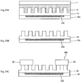
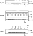
- A is a plan view showing an example of a hologram pattern
- B is a sectional view taken along the line AA of A.
- A is a plan view showing an example of a hologram pattern
- B to D are cross-sectional views taken along the line AA.
- It is a top view which shows an example of a hologram pattern.
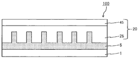
- Transfer Sheet 1 to 5 and 18 to 26 are schematic cross-sectional views showing an example of the transfer sheet 100 of the present disclosure.
- the transfer sheet 100 of the present disclosure is not limited to the illustrated form.
- the transfer sheet 100 of the present disclosure may have a partial configuration removed from the illustrated form.
- the transfer sheet 100 of the present disclosure may be provided with another configuration in the illustrated form.
- the transfer sheet 100 of the present disclosure includes all forms in which the illustrated forms are combined.
- the transfer sheet 100 of the present disclosure may be a combination of various forms of the transfer sheet 100 described below as appropriate.
- the transfer sheet 100 of the present disclosure has a base material 1, a relief layer 5, a coloring material layer 40, and a first transfer layer 20 (see FIGS. 1 to 5).
- the color material layer 40 and the first transfer layer 20 are provided on the relief layer 5 in a surface-sequential manner.
- the transfer sheet 100 of the present disclosure has a base material 1, a relief layer 5, and a first transfer layer 20 (see FIGS. 18 to 26).
- the first transfer layer 20 can be peeled off from the relief layer 5.
- the surface of the relief layer 5 on the first transfer layer 20 side has an uneven pattern.
- the surface of the first transfer layer 20 on the relief layer 5 side has a hologram pattern that follows the uneven pattern of the relief layer 5.
- the transfer sheet 100 of the present disclosure having the color material layer 40 can form a thermal transfer image on the transferred body 150 in the color material layer 40.
- the transfer sheet 100 of the present disclosure can impart a hologram feeling to the transferred body 150 on which the thermal transfer image is formed.
- the transfer sheet 100 of the present disclosure can produce a printed matter having a holographic feeling and a decorative product having a holographic feeling.
- the transfer sheet 100 of the present disclosure can transfer the first transfer layer 20 to the transferred body 150 to manufacture a decorative product 300 in which the first surface of the first transfer layer 20 is located on the outermost surface.
- the manufactured decorative product 300 has a hologram pattern located on the outermost surface, and a portion of the transferred body 150 that overlaps with the first transfer layer 20 has a hologram feeling.
- each configuration of the transfer sheet 100 of the present disclosure will be described with an example.
- the base material 1 holds the relief layer 5 and the first transfer layer 20.
- the base material 1 has a single-layer structure or a laminated structure including a resin base material.
- the base material 1 has a single-layer structure or a laminated structure including a paper base material.
- the base material 1 has a laminated structure including one or more resin base materials and one or more paper base materials.
- the base material 1 has a laminated structure in which a paper base material, an adhesive film, and a paper base material are laminated in this order.
- the resin base material examples include polyester, polyolefin, polyvinyl chloride, polymethacrylate, polypropylene, polycarbonate, cellulose acetate, polyethylene derivatives, polyamides, and polymethylpentene.
- the polyester examples include polyethylene terephthalate and polyethylene naphthalate.
- the resin base material may be stretched or unstretched.
- the base material 1 has a single-layer structure or a laminated structure including a void layer.
- the first transfer layer 20 includes the receiving layer 45
- the base material 1 can form a high-concentration image 200 on the receiving layer 45.
- a resin base material or the like having a void inside can be exemplified.
- inorganic particles are kneaded into a polymer, and when the mixture is stretched, voids are generated by using the inorganic particles as nuclei, or a polymer that is incompatible with the main resin is mixed and the mixture is mixed. Examples thereof include those in which voids are generated when the mixture is stretched.
- the polymer may be one kind or two or more kinds.
- the voids contained in the void layer may be referred to as microvoids or vacancies.
- the void layer may be referred to as a porous layer, a porous film, or the like.
- Paper substrates include high-quality paper, coated paper, resin-coated paper, art paper, cast-coated paper, paperboard, synthetic paper (polyolefin-based, polystyrene-based), synthetic resin or emulsion-impregnated paper, synthetic rubber latex-impregnated paper, synthetic resin. Examples thereof include an inner paper, a cellulose fiber paper, and the like.
- the thickness of the base material 1 is not limited, but is preferably 1 ⁇ m or more and 300 ⁇ m or less.
- the transfer sheet 100 of the present disclosure has a relief layer 5 provided on the base material 1 (see FIGS. 1 to 5 and 18 to 26).
- the first surface of the relief layer 5 has an uneven pattern corresponding to the hologram pattern of the first surface of the first transfer layer 20.
- the first surface of the relief layer 5 has an uneven pattern capable of forming a hologram pattern on the first surface of the first transfer layer 20.
- the uneven pattern of the relief layer 5 includes a plurality of concave portions and a plurality of convex portions.
- the first surface of the first transfer layer 20 has a hologram pattern that follows the uneven pattern of the first surface of the relief layer 5.
- the concave portion of the uneven pattern of the relief layer 5 corresponds to the convex portion of the hologram pattern of the first transfer layer 20.
- the convex portion of the uneven pattern of the relief layer 5 corresponds to the concave portion of the hologram pattern of the first transfer layer 20.
- the uneven pattern of the relief layer 5 may be determined according to the hologram pattern of the first transfer layer 20.
- the relief layer 5 has a releasable first surface.
- the surface of the uneven pattern has releasability.
- the relief layer 5 in this form has good peelability of the first transfer layer 20.
- the relief layer 5 has no releasability on the first surface.
- the surface of the uneven pattern does not have releasability. In the case of the relief layer 5 of this form, it is sufficient to impart releasability to the first surface of the first transfer layer 20.
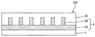
- the relief layer 5 is composed of one member (see FIGS. 1 to 3 and 18 to 20).
- the relief layer 5 is composed of one member having releasability.
- the relief layer 5 contains a component having releasability.
- the components having releasability include waxes, silicone wax, silicone resin, silicone-modified resin, fluororesin, fluorine-modified resin, polyvinyl alcohol, acrylic resin, heat-crosslinkable epoxy-amino resin, and heat-crosslinkable alkyd-amino.
- a resin or the like can be exemplified.
- the relief layer 5 as an example contains inorganic particles. Examples of the inorganic particles include titanium oxide and silica.
- the relief layer 5 may contain one kind of component or may contain two or more kinds of components.
- the member before the uneven pattern is formed is embossed with a plate having the uneven pattern corresponding to the uneven pattern of the relief layer 5 to form the uneven pattern.
- Method (ii) a method of forming a concavo-convex pattern by machining a member before the concavo-convex pattern is formed, (iii) a method of laser-machining a member before the concavo-convex pattern is formed to form an uneven pattern, etc.
- the member before the unevenness pattern is formed may be read as a laminate of the base material 1 and the member before the unevenness pattern is formed.
- this laminated body As a method of forming this laminated body, a method of laminating the base material 1 and a member before the unevenness pattern is formed, and a coating liquid which is a member before the unevenness pattern is formed on the base material 1 are applied.
- An example of a method of forming by drying can be exemplified.
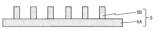
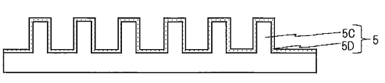
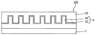
- the relief layer 5 is composed of a plurality of members (see FIGS. 6, 7, and 21). 6 and 7 are partial cross-sectional views showing an example of the relief layer 5.
- the relief layer 5 is composed of a relief layer support portion 5A and a relief layer convex portion 5B (see FIGS. 6 and 21).
- the relief layer support portion 5A and the relief layer convex portion 5B may be the same member or may be different members.
- the relief layer support portion 5A and the relief layer convex portion 5B have releasability.
- either one or both of the relief layer support portion 5A and the relief layer convex portion 5B do not have releasability.
- a method for forming the uneven pattern of the relief layer 5 in this form (iv) a method of applying and drying a coating liquid to be the relief layer convex portion 5B on the relief layer support portion 5A having no uneven pattern, (v).
- An example of a method of attaching a member to be the relief layer convex portion 5B to the relief layer support portion 5A can be exemplified.
- the relief layer support portion 5A may be read as a laminate in which the base material 1 and the relief layer support portion 5A are laminated.
- a method for forming this laminated body As a method for forming this laminated body, a method of laminating the base material 1 and the relief layer support portion 5A, a method of applying a coating liquid to be the relief layer support portion 5A on the base material 1, and drying the method, and the like are used. It can be illustrated.
- the relief layer 5 is composed of a relief portion 5C and a release layer 5D (see FIGS. 7 and 22).
- the relief portion 5C does not have releasability.
- the relief layer 5 of this form can be formed by applying the coating liquid of the release layer 5D to the surface of the relief layer 5 formed by the above methods (i) to (v) and drying.
- a laminated body in which the release layer 5D is formed on the member before the unevenness pattern is formed can be prepared, and this laminated body can be formed by embossing.
- the component of the release layer 5D those described in the above-mentioned member having mold releasability can be appropriately selected and used.
- the relief layer 5 has a thickness excluding the convex portion (see the reference numeral “Tr” in FIGS. 1A and 18) of 0.01 ⁇ m or more and 10 ⁇ m or less.
- the first transfer layer 20 is provided on the first surface side of the relief layer 5.
- the first transfer layer 20 has a single-layer structure or a laminated structure including a protective layer 25 (see FIGS. 1 to 5).
- the first transfer layer 20 does not have to include the protective layer 25.
- the first transfer layer 20 can have various forms exemplified below.
- the first transfer layer 20 can be peeled off from the relief layer 5.
- the first surface of the first transfer layer 20 has a hologram pattern that follows the uneven pattern of the relief layer 5.
- the transfer sheet 100 of the present disclosure can position the first surface of the first transfer layer 20 on the outermost surface of the transfer target 150 by transferring the first transfer layer 20 to the transfer target 150.
- the transfer sheet 100 of the present disclosure can express a hologram pattern on the outermost surface of the transferred body 150 by transferring the first transfer layer 20 to the transferred body 150.
- a hologram feeling can be imparted to a portion where the transferred body 150 and the first transfer layer 20 overlap each other and the first surface of the first transfer layer 20 is exposed.
- the holographic feeling in the present disclosure means a state in which incident light is diffracted by surface irregularities and the object appears to have a color different from that of the material.
- the transfer sheet 100 of the present disclosure is an uneven pattern possessed by the first surface of the relief layer 5, and a hologram pattern is formed on the first surface of the first transfer layer 20 before transfer.
- the first transfer layer 20 does not have a holographic feeling. That is, the transfer sheet 100 of the present disclosure does not have a hologram feeling even when the first transfer layer 20 is viewed in a plan view from the relief layer 5 side.
- the first transfer layer 20 of the transfer sheet 100 of the present disclosure has a hologram pattern on the first surface, but does not have a holographic feeling at the stage before transfer.
- the first transfer layer 20 overlaps with a non-filling region described later.
- the first transfer layer 20 has transparency so that the surface of the transfer target 150 can be visually recognized from the first transfer layer 20 side when the first transfer layer 20 is transferred to the transfer target 150.
- transparent includes colorless transparent, colored transparent, and translucent.
- any of the constituent members constituting the first transfer layer 20 contains a colorant.
- the first transfer layer 20 has no transparency.
- the first transfer layer 20 has transparency. The first transfer layer 20 having transparency and the first transfer layer 20 having no transparency may be provided surface-sequentially on the first surface side of the relief layer 5.
- the first transfer layer 20 is transferred to the transferred body 150 and a hologram pattern is expressed on the outermost surface, whereby the hologram is transferred to the portion of the transferred body 150 to which the first transfer layer 20 is transferred.
- a feeling can be imparted (see FIGS. 8C, 9D, 10D, 11D, 27B, 28C, 29C, 30C, 31B).
- 8C, 9D, 10D, and 11D are schematic cross-sectional views showing an example of a printed matter 300 manufactured by using the transfer sheet 100 of the present disclosure.
- 27B, 28C, 29C, 30C, and 31B are schematic cross-sectional views showing an example of a decorative item 300 manufactured using the transfer sheet 100 of the present disclosure.
- the hologram pattern that appears on the outermost surface of the transfer of the first transfer layer 20 is the difference in the refractive index between the air and the interface of the unevenness that forms the hologram pattern. Can be granted.
- Such a first transfer layer 20 can have a larger difference in refractive index than a conventional transfer layer that imparts a hologram feeling by utilizing the difference in refractive index between materials, and can impart a strong hologram feeling to the transferred object. ..
- a transfer layer having a hologram layer and a reflective layer and capable of imparting a hologram feeling by the difference in the refractive index between the hologram layer and the reflective layer can be exemplified.
- FIG. 13A, 14A, 15 and 16 are partial plan views showing an example when the first transfer layer 20 is viewed in a plan view from the first surface side, and is a hologram included in the first surface of the first transfer layer 20.
- An example of the pattern is shown.
- FIG. 13B is a schematic cross-sectional view showing an example of the AA cross section of the first transfer layer 20 of FIG. 13A.
- 14B to 14D are schematic cross-sectional views showing an example of the AA cross section of the first transfer layer 20 of FIG. 14A.
- An example hologram pattern is a structure in which concave portions and convex portions are regularly arranged.
- the hologram pattern of the first transfer layer 20 is not limited, and it is sufficient that the hologram feeling can be expressed by the difference in the refractive index between the air and the first surface of the first transfer layer 20.
- the hologram pattern of the first transfer layer 20 is not limited to the illustrated form, the shape described below, and the like.
- the hologram pattern has a linear shape when viewed in a plan view (see FIGS. 13A and 14A).
- a plurality of convex portions extending continuously in one direction are regularly arranged in a direction orthogonal to one direction.
- the direction in which the convex portion continuously extends is the longitudinal direction of the transfer sheet 100.
- the hologram pattern of this form can stabilize the peeling of the plate from the relief layer 5 when the relief layer 5 is embossed by a roll-to-roll method using a plate having an uneven pattern, and the relief layer 5 has a defect. It is possible to form a non-concavo-convex pattern. Further, it is possible to suppress foam biting when the coating liquid is applied to the formed relief layer 5 and dried to form the first transfer layer 20.
- the hologram pattern has a square grid shape when viewed in a plan view (see FIG. 15). As an example, the hologram pattern has a triangular lattice shape when viewed in a plan view (see FIG. 16).
- the pitch between the protrusions forming the hologram pattern is not limited, but is preferably 0.1 ⁇ m or more and 10 ⁇ m or less, and more preferably 0.5 ⁇ m or more and 5 ⁇ m or less.
- This form of hologram pattern can strongly express a holographic feeling.
- the pitch between the convex portions forming the hologram pattern in the present disclosure means the distance between the centers of the adjacent convex portions when the first transfer layer 20 is viewed in a plan view from the first surface side.
- the pitch between the convex portions forming the hologram pattern may be read as the pitch between the concave portions forming the hologram pattern, the width of the convex portions forming the hologram pattern, and the width of the concave portions forming the hologram pattern.
- the pitch between the recesses forming the hologram pattern means the distance between the centers of the adjacent recesses (see the reference numeral “P2” in FIGS. 13 to 16) when the first transfer layer 20 is viewed in a plan view from the first surface side. ..
- the width of the convex portion forming the hologram pattern means the width of the convex portion when the hologram pattern is viewed in a plan view (see the reference numeral “W1” in FIGS. 13 to 16).
- the height of the convex portion in the hologram pattern is not limited, but is preferably 0.1 ⁇ m or more and 2 ⁇ m or less, and more preferably 0.15 ⁇ m or more and 1 ⁇ m or less.
- the hologram pattern of this form can strongly express a holographic feeling, and can maintain this holographic feeling even when a fingerprint or the like adheres to the first surface of the first transfer layer 20.
- the cross-sectional shape of the recess forming the hologram pattern is not limited, and is rectangular (see FIGS. 14C, 27B, 28C, 29C, 30C, 31B), trapezoidal (see 14B, 14D), and V-shaped. (See FIG. 13B), a stepped shape, a shape having a curvature, and the like can be exemplified. As the shape having a curvature, a U-shape or the like can be exemplified.
- the cross-sectional shape of the convex portion in the hologram pattern is not limited, and is rectangular (see FIGS. 14C, 27B, 28C, 29C, 30C, 31B), trapezoidal (see FIG. 14B), and triangular (see FIG. 13B, FIG. (See FIG. 14D), a shape having a curvature and the like can be exemplified.
- the concave cross-sectional shape forming the hologram pattern has an inner wall surface with a slope (see FIGS. 13B, 14B, and 14D).
- the hologram pattern of this form facilitates the formation of the hologram pattern.
- the thickness of the first transfer layer 20 excluding the convex portion of the hologram pattern is 0.01 ⁇ m or more and 10 ⁇ m or less.
- the first transfer layer 20 has a single-layer structure (see FIG. 18) or a laminated structure including a protective layer 25 (see FIGS. 19 and 20).
- the protective layer 25 is located closest to the relief layer 5 among the layers constituting the first transfer layer 20.
- the protective layer 25 has a hologram pattern on the surface on the relief layer 5 side (see FIGS. 1A, 1B, 2 to 5, 19, and 20).
- the components of the protective layer 25 include acrylic resin, polyester, polycarbonate, vinyl resin such as vinyl chloride-vinyl acetate copolymer, ultraviolet absorbing resin, epoxy resin, polystyrene, polyurethane, urethane-modified acrylic, and acrylic-modified urethane. Examples thereof include a silicone-modified resin, a mixture of each of these resins, an ionized radiation curable resin, and an ultraviolet curable resin.
- the component contained in the protective layer 25 may be one kind or two or more kinds.
- the protective layer 25 is located closest to the relief layer 5 among the layers constituting the first transfer layer 20, and contains a component having releasability.
- the releasable component the component described in the above-mentioned releasable member can be appropriately selected and used.
- This form of the protective layer 25 is suitable when the first surface of the relief layer 5 does not have releasability.
- the protective layer 25 is located closest to the relief layer 5 among the layers constituting the first transfer layer 20, and contains titanium oxide. The protective layer 25 in this form can impart a stronger hologram feeling to the transferred body 150 to which the first transfer layer 20 is transferred.
- the method of forming the protective layer 25, can be formed by applying a coating liquid and drying it.
- the coating method of the coating liquid is not limited, and a conventionally known coating method can be appropriately selected and used. In this method, a hologram pattern that follows the uneven pattern of the relief layer 5 can be easily formed on the surface of the protective layer 25 on the relief layer 5 side.
- the coating method include a gravure printing method, a screen printing method, and a reverse coating method using a gravure plate. Further, other coating methods can also be used. This also applies to the methods for forming various layers described later.
- the protective layer 25 may be read as the first transfer layer 20.
- the first transfer layer 20 has a laminated structure in which a peeling layer and a protective layer 25 are laminated in this order.
- the surface of the release layer on the relief layer 5 side has a hologram pattern.
- the component of the release layer the component described in the above-mentioned member having releasability can be exemplified. This form is suitable when the first surface of the relief layer does not have releasability.
- the first transfer layer 20 has a laminated structure in which the protective layer 25 and the heat seal layer 30 are laminated in this order from the relief layer 5 side (see FIGS. 1B and 19).
- the first transfer layer 20 in this form can improve the adhesion between the transfer target 150 and the first transfer layer 20 when the first transfer layer 20 is transferred to the transfer target 150.
- the components of the heat seal layer 30 include acrylic resin, polyurethane, polyolefin, polyester, epoxy resin, urea resin, melamine resin, phenol resin, vinyl acetate, vinyl resin such as vinyl chloride-vinyl acetate copolymer, and cyanoacrylate. Can be exemplified.
- the component contained in the heat seal layer 30 may be one kind or two or more kinds.
- the method for forming the heat seal layer 30 is not limited, and the heat seal layer 30 can be formed by applying a coating liquid and drying it.
- the thickness of the heat seal layer 30 is preferably 0.2 ⁇ m or more and 10 ⁇ m or less, and more preferably 0.5 ⁇ m or more and 2.5 ⁇ m or less.
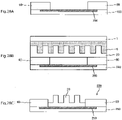
- FIG. 17C is a comparative transfer sheet 100X manufactured by the following method.
- the transfer sheet of FIG. 17C differs from the transfer sheet 100 of the present disclosure in that a primer layer 30'rather than a relief layer 5 is provided between the base material 1 and the coloring material layer 40.
- the relief layer 5 is formed on a part of the base material, and the first transfer layer 20 is formed on the relief layer 5.
- the primer layer 30' is formed on the other part of the base material 1, and the coloring material layer 40 is formed on the primer layer 30'.
- a resin layer 5'before the uneven pattern is formed is provided on a part of the base material 1 (see FIG.
- the relief layer 5 is formed in a portion overlapping the first transfer layer 20 (relief layer forming region in the figure).
- the resin layer 5' stretches in the plane direction (see FIG. 17B).
- the color material layer 40 is accurately set in the planned area for forming the color material layer. Cannot be formed.
- the first transfer layer 20 and the coloring material layer 40 are sequentially provided on the first surface side of the relief layer 5.
- the transfer sheet 100 of the present disclosure does not have a problem of position accuracy due to the relief layer 5 reaching the planned region for forming the color material layer.
- the transfer sheet 100 of the present disclosure has good positional accuracy of the first transfer layer 20 and the color material layer 40.
- the color material layer 40 having good position accuracy can form a thermal transfer image without color shift.
- the color material layer 40 having good position accuracy can suppress abnormal transfer when forming a thermal transfer image.
- the first transfer layer 20 has a single-layer structure or a laminated structure including a receiving layer 45 (see FIG. 20).
- the first transfer layer 20 has a single-layer structure composed of only the receiving layer 45, and the surface of the receiving layer 45 on the relief layer 5 side has a hologram pattern.
- the first transfer layer 20 has a laminated structure in which the first protective layer 25 and the receiving layer 45 are laminated in this order from the relief layer 5 side (see FIG. 20).
- An image 200 can be formed on the receiving layer 45 by a sublimation type thermal transfer method.
- the receiving layer 45 contains a component that can accept the sublimation dye.
- Acrylic resin, acrylic-styrene copolymer, polyolefin, polyvinyl chloride, polyvinylidene chloride, polyvinyl acetate, vinyl chloride-vinyl acetate copolymer, ethylene-vinyl acetate copolymer can be used as components that can accept sublimative dyes.
- Polyacrylic acid ester polyester, polystyrene, polyamide, ethylene, copolymer of olefin and other vinyl polymer, ionomer, cellulose resin, polycarbonate, epoxy resin, polyvinylpyrrolidone, polyvinyl alcohol, gelatin and the like can be exemplified.
- the polyolefin include polypropylene and the like.
- the polyester include polyethylene terephthalate and polybutylene terephthalate.
- the component contained in the receiving layer 45 may be one kind or two or more kinds.
- the receiving layer 45 can be formed by applying the coating liquid of the receiving layer 45 and drying it.
- the thickness of the receiving layer 45 is not limited, but is preferably 0.5 ⁇ m or more and 20 ⁇ m or less.
- the receiving layer 45 may be used as an image layer.
- the image 200 can be formed on the image layer by various printing methods. Examples of various image forming methods include a melt-type thermal transfer method, an inkjet printing method, and a toner printing method (laser printing method).
- the first protective layer 25 or the like may be used as an image layer.
- a part of the first surface of the relief layer 5 has a fill-in-the-blank area in which at least a part of the internal space of the concave portion of the concave-convex pattern is filled with the fill-in-the-blank layer 55.
- the other portion of the first surface of the relief layer 5 as an example has a non-filling area in which the space in the recess of the concave-convex pattern is not filled with the filling layer 55.
- the first surface of the relief layer 5 has a fill-in-the-blank area having no unevenness pattern corresponding to the hologram pattern and a non-fill-in-the-blank area having the unevenness pattern corresponding to the hologram pattern.
- the fill-in-the-blank area in the present disclosure means a region having no unevenness pattern corresponding to the hologram pattern.
- the non-filled area in the present disclosure means a region having an uneven pattern corresponding to the hologram pattern. If the uneven pattern corresponding to the hologram pattern can be maintained, a part of the space in the recess of the non-filling region of the relief layer 5 may be filled with the filling layer 55.
- the first surface of the relief layer 5 has a fill-in-the-blank area having no unevenness pattern corresponding to the hologram pattern and a non-fill-in-the-blank area having the unevenness pattern corresponding to the hologram pattern.
- the color material layer 40 of the transfer sheet 100 of the present disclosure overlaps with the hole filling region.
- the first transfer layer 20 of the transfer sheet 100 of the present disclosure does not overlap with the fill-in-the-blank area, but overlaps with the non-fill-in-the-blank area.
- the second transfer layer 60 of the transfer sheet 100 as an example of the present disclosure overlaps with the hole filling region.
- the hole filling layer 55 is provided so that a part of the internal space of the concave portion of the concave-convex pattern of the relief layer 5 remains (see FIG. 3).
- the thickness of the fill-in-the-blank layer 55 in this form is thinner than the depth of the recesses in the uneven pattern.
- the internal space of the recess may be filled with the fill-in-the-blank layer 55 to the extent that the surface of the second transfer layer after transfer does not have a hologram pattern. good.
- the hole filling layer 55 is provided so as to fill the entire internal space of the concave portion of the concave-convex pattern of the relief layer 5 (see FIGS. 1 and 23).
- the thickness of the fill-in-the-blank layer 55 in this form is the same as the depth of the recesses in the uneven pattern.
- the fill-in-the-blank layer 55 in this form can flatten the color material layer 40 provided on the fill-in-the-blank layer 55.
- the color material layer 40 in this form can have a uniform thickness and can form a good thermal transfer image 200 in which density unevenness is suppressed.
- the fill-in-the-blank layer 55 is provided so as to fill the entire internal space of the concave portion of the concave-convex pattern of the relief layer 5, and the surface of the relief layer 5 is covered with the fill-in-the-blank layer (see FIGS. 2 and 24). ).
- the thickness of the fill-in-the-blank layer 55 in this form is thicker than the depth of the recess.
- the fill-in-the-blank layer 55 in this form can flatten the color material layer 40 provided on the fill-in-the-blank layer 55.
- the color material layer 40 in this form can have a uniform thickness and can form a good thermal transfer image 200 in which density unevenness is suppressed.
- the fill-in-the-blank layer 55 in this form can flatten the second transfer layer 60 that overlaps the fill-in-the-blank area.
- the hole filling layer 55 has a mold releasable surface.
- the fill-in-the-blank layer 55 as an example is a release layer.
- the component of the release layer the component described in the member having releasability can be appropriately selected and used.
- the fill-in-the-blank layer 55 in this form can improve the releasability of the molten ink layer when the coloring material layer 40 is used as the molten ink layer.
- the fill-in-the-blank layer 55 has no mold releasability on its surface.
- the fill-in-the-blank layer 55 as an example is a primer layer.
- the component of the primer layer the component described in the heat seal layer 30 and the like can be exemplified.
- the hole filling layer 55 may have a single-layer structure or a laminated structure.
- the hole filling layer 55 has a laminated structure in which a member having adhesiveness is located on the surface.
- the hole filling layer 55 has a laminated structure in which a member having releasability is located on the surface.
- the fill-in-the-blank layer 55 in a preferred form has an adhesive surface and is in contact with the color material layer 40.
- the fill-in-the-blank layer 55 in a preferred form is a primer layer.
- the fill-in-the-blank layer 55 in this form can improve the adhesion between the fill-in-the-blank layer 55 and the dye layer when the color material layer 40 is used as the dye layer.
- the first surface of the relief layer 5 has releasability, and the surface of the hole filling layer 55 has adhesiveness.
- the surface of the fill-in-the-blank layer 55 is in contact with the color material layer.
- the transfer sheet 100 in this form has good peelability of the first transfer layer 20, and can improve the adhesion between the hole filling layer 55 and the dye layer when the coloring material layer 40 is used as the dye layer.
- the fill-in-the-blank layer 55 has an adhesive surface, and the surface of the fill-in-the-blank layer 55 is covered with a release layer.
- the fill-in-the-blank layer 55 in this form can improve the releasability of the molten ink layer when the coloring material layer 40 is used as the molten ink layer.
- the method of forming the hole filling layer 55 is not limited, and a method of applying and drying the coating liquid of the hole filling layer 55 can be exemplified.
- a second transfer layer 60 may be provided on the relief layer 5 so that a gap is formed in the recess of the relief layer 5 (see FIG. 25).
- the relief layer 5 may be provided on a part of one surface of the base material 1, and the second transfer layer 60 may be provided on the other part of the base material 1 on which the relief layer 5 is not provided (Fig.). 26).
- various layers may be provided between the base material 1 and the second transfer layer 60. Examples of various layers include a release layer, a primer layer and the like.
- the transfer sheet 100 as an example of the present disclosure has a color material layer 40 (see FIGS. 1 to 5).
- the coloring material layer 40 is a dye layer containing a sublimation dye.
- the color material layer 40 as an example is a molten ink layer.
- the color material layer 40 overlaps with the hole filling region on the first surface of the relief layer 5.
- the thermal transfer image 200 can be formed by the color material layer 40.
- the transfer sheet 100 of the present disclosure can realize the formation of the thermal transfer image 200 and the transfer of the first transfer including the protective layer 25 with one transfer sheet.
- the number of the color material layer 40 overlapping the fill-in-the-blank area may be one (see FIGS.
- the transfer sheet 100 in the form shown in FIG. 4 has a yellow dye layer 40Y, a magenta dye layer 40M, and a cyan dye layer 40C. These dye layers overlap with the fill-in-the-blank area. One or more dye layers and one or more molten ink layers may be provided surface-sequentially.
- the coloring material layer 40 is a dye layer containing a sublimation dye.
- the resin component contained in the dye layer include cellulose resin, polyvinyl alcohol, vinyl resin, acrylic resin, polyurethane, polyamide, polyester and the like.
- the vinyl resin include polyvinyl acetate, polyvinyl butyral, polyvinyl acetal, and polyvinylpyrrolidone.
- the cellulose resin include ethyl cellulose, hydroxyethyl cellulose, ethyl hydroxycellulose, methylcellulose, cellulose acetate and the like.
- Sublimable dyes include diarylmethane dyes, triarylmethane dyes, thiazole dyes, merocyanine dyes, pyrazolone dyes, methine dyes, indian aniline dyes, acetophenone azomethins, pyrazoloazomethines, imidazole azomethines, imidazole azomethines, Azomethine dyes such as pyridone azomethine, xanthene dyes, oxazine dyes, dicyanostyrene, cyanostyrene dyes such as tricyanostyrene, thiazine dyes, azine dyes, acridin dyes, benzeneazo dyes, pyridone azo, thiophenazo, Azo dyes such as isothiazole azo, pyrrol azo, pyrazole azo, imidazole azo, thiadiazol azo, triazol azo, disazo,
- red dyes such as MSRedG (Mitsui Toatsu Chemical Co., Ltd.), Macrolex Red Violet R (Bayer), Ceres Red 7B (Bayer), Samaroon Red F3BS (Mitsubishi Chemical Co., Ltd.), Holon Brilliant.
- Yellow dyes such as Yellow 6GL (Clariant), PTY-52 (Mitsubishi Chemical Co., Ltd.), Macrolex Yellow 6G (Bayer), Kayaset (registered trademark) Blue 714 (Nippon Kayaku Co., Ltd.), Holon Brilliant Blue SR (Clariant), MS Blue 100 (Mitsui Toatsu Chemical Co., Ltd.), C.I. I.
- a blue dye such as Solvent Blue 63 can be exemplified.
- the content of the resin component with respect to the total mass of the dye layer is preferably 20% by mass or more.
- the dye layer of this form can sufficiently retain the sublimable dye in the dye layer and has good storage stability.
- the upper limit of the content of the binder resin may be appropriately set according to the content of the sublimation dye or any additive.
- the content of the sublimable dye is preferably 50% by mass or more and 350% by mass or less, and more preferably 80% by mass or more and 300% by mass or less with respect to the total mass of the resin component.
- the dye layer in this form can form a thermal transfer image 200 having a high printing density, and can have good storage stability.
- the color material layer 40 as an example is a molten ink layer.
- a molten ink layer conventionally known in the field of thermal transfer sheets can be appropriately selected and used.
- the molten ink layer contains a colorant.
- the colorant include dyes, organic color pigments, fluorescent pigments, titanium oxide, zinc oxide, carbon black, iron oxide, iron yellow, ultramarine blue, hologram powder, aluminum powder, metallic pigments, and pearl pigments.
- the molten ink layer contains one or both of a resin component and a wax.
- the transfer sheet 100 as an example of the present disclosure has a second transfer layer 60 that overlaps the hole filling region of the relief layer 5 (see FIG. 5).
- the second transfer layer 60 can be peeled off from the relief layer 5 side.
- the surface on the relief layer 5 side does not have a hologram pattern.
- the surface of the second transfer layer 60 on the base material 1 side may have an uneven pattern different from the hologram pattern.
- the surface on the relief layer 5 side does not have a hologram pattern.
- the surface of the second transfer layer 60 on the base material 1 side may have an uneven pattern different from the hologram pattern.
- the surface on the relief layer 5 side does not have a hologram pattern.
- the surface of the second transfer layer 60 on the base material 1 side may have an uneven pattern different from the hologram pattern.
- An uneven pattern different from the hologram pattern means an uneven pattern that cannot express a holographic feeling.
- the transfer sheet 100 as an example of the present disclosure is provided with a second transfer layer 60 in a surface-sequential manner with the first transfer layer 20 (see FIGS. 23 to 25).
- the second transfer layer 60 can be peeled from the base material 1 side by using the surface of the second transfer layer 60 on the base material 1 side as a peeling interface.
- the surface of the second transfer layer 60 on the base material 1 side does not have a hologram pattern.
- the surface of the second transfer layer 60 on the base material 1 side does not have a hologram pattern.
- the surface of the second transfer layer 60 on the base material 1 side may have an uneven pattern different from the hologram pattern.
- the second transfer layer 60 may have a single-layer structure or a laminated structure.
- the second transfer layer has a single-layer structure or a laminated structure including a protective layer.
- the second transfer layer has a laminated structure in which the protective layer 25 and the heat seal layer 30 are laminated in this order from the first surface side of the relief layer 5.
- the second transfer layer 60 has a laminated structure in which a protective layer and a heat seal layer 30 are laminated in this order from the base material 1 side.
- the protective layer 25 has peelability.
- the second transfer layer has a single-layer structure or a laminated structure including a heat-seal layer 30 located closest to the first surface of the relief layer 5 among the layers constituting the second transfer layer 60. ..
- the second transfer layer 60 has a single-layer structure or a laminated structure including the receiving layer 45.
- the second transfer layer 60 has a laminated structure in which a protective layer and a receiving layer 45 are laminated in this order from the base material 1 side.
- the second transfer layer is a single-layer structure or a laminated structure including a peeling layer located closest to the first surface of the relief layer 5 among the layers constituting the second transfer layer 60.
- the second transfer layer 60 of this form is suitable when the second transfer layer 60 is in contact with the hole filling layer 55 and the hole filling layer 55 has adhesiveness.
- the components of the various layers the components of the various layers described in the first transfer layer 20 can be appropriately selected and used.
- the second transfer layer 60 may satisfy the requirement that it can be peeled off from the base material 1 side, and the functions of the layer constituting the second transfer layer 60 and the second transfer layer 60 are not limited.
- the transfer sheet 100 as an example of the present disclosure has a functional layer provided in a surface-sequential manner with the first transfer layer 20.
- the functional layer as an example cannot be peeled off from the base material 1 side.
- the functional layer is a dye layer containing a sublimable dye.
- the functional layer has a laminated structure in which a primer layer and a dye layer are sequentially provided from the base material 1 side.
- the functional layer as an example includes a plurality of dye layers.
- the transfer sheet 100 is provided with one or a plurality of dye layers of each color of yellow, magenta, and cyan in a surface-sequential manner with the first transfer layer 20.
- the functional layer as an example is a glossy layer.
- An example functional layer is a heat seal layer.
- the surface of the functional layer on the base material 1 side may or may not have an uneven pattern.
- the transfer sheet 100 has a back surface layer (not shown) provided on the surface of the base material 1 opposite to the relief layer 5.
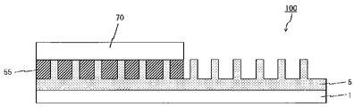
- the relief layer 5 is provided on the base material 1, and the third transfer layer 70 is provided on the relief layer 5 (see FIG. 33).
- the first surface of the relief layer 5 has a fill-in-the-blank area in which the internal space of the concave portion of the concave-convex pattern is filled with the fill-in-the-blank layer 55, and a non-fill-in area in which the internal space of the concave portion of the concave-convex pattern is not filled in the fill-in-the-blank layer 55.
- the surface of at least a part of the non-filled area is exposed.
- the configurations described above can be appropriately selected and used.
- the third transfer layer 70 is provided at least in a part of the hole filling region of the relief layer 5.
- the surface of the third transfer layer 70 after transfer does not have a hologram pattern.
- the transfer sheet 100 of another embodiment of the present disclosure transfers the third transfer layer 70 to the transferred body 150 (see FIG. 34A).
- the third transfer layer 70 transferred to the transfer target is overlapped with the exposed portion of the non-filled area of the transfer sheet 100 of the other embodiment of the present disclosure, and energy is applied to the transfer sheet 100 side (see FIG. 34B). ).
- a hologram pattern corresponding to the uneven pattern of the relief layer 5 can be formed on the surface of the third transfer layer 70 (see FIG. 34C).
- the non-filled area portion of the relief layer 5 functions as an embossed plate.
- the first transfer layer 20 is provided on the relief layer 5 having the uneven pattern, and the first transfer layer 20 after the transfer has a hologram pattern corresponding to the uneven pattern. .. That is, in the transfer sheet 100 of this form, the hologram pattern formed on the surface of the first transfer layer 20 is uniquely determined by the uneven pattern of the relief layer 5.
- the depth of the uneven pattern of the hologram formed on the third transfer layer 70 due to the amount of energy applied to the transfer sheet 100 and the printing pressure applied to the transfer sheet 100. Can be changed.
- a hologram pattern in which the depth of the recess is shallower than that of the uneven pattern of the non-filled region portion of the relief layer 5.
- a hologram pattern can be formed only on the portion to which the energy is applied.
- a hologram pattern can be formed on an arbitrary portion of the third transfer layer 70 by appropriately selecting a region to which energy is applied.
- the following form may be used. These can be applied to the transfer sheet 100 in the form.
- a concavo-convex layer and a non-concave layer are provided surface-sequentially on the base material 1, and a third transfer layer is provided on the non-concave layer (not shown).
- the surface of at least a part of the uneven layer is exposed.
- the uneven layer has unevenness capable of forming a hologram pattern.
- a member before the unevenness pattern is formed is provided on the base material 1, and the unevenness pattern is formed on a part of this member.
- the uneven pattern may be any pattern that can form a hologram pattern.
- the third transfer layer 70 is provided on the region where the uneven pattern is not formed.
- the third transfer layer 70 has a single-layer structure or a laminated structure including a release layer.
- the third transfer layer 70 has a laminated structure in which a release layer and an adhesive layer are laminated in this order from the base material 1 side.
- the peeling layer may be read as a protective layer.
- An ionizing radiation curable resin, an ultraviolet curable resin, or the like is used as a component of the release layer and the protective layer, and after forming a hologram uneven pattern on the third transfer layer after transfer, the third transfer layer 70 is cured. May be good.
- the third transfer layer 70 can be cured by using an ultraviolet irradiation device or the like.
- the transfer sheet 100 of another embodiment of the present disclosure may be combined with the configurations of the transfer sheets of various forms described above.
- the transfer sheet 100 of another embodiment of the present disclosure may have another layer provided in a surface-sequential manner with the third transfer layer 70.
- the other layer include the first transfer layer 20, the second transfer layer 60, the color material layer 40, and the like described above.
- the recording medium 110 of the present disclosure is provided with an image forming layer 115 on one surface side of the transparent substrate 111, and the other surface of the transparent substrate 111 has a hologram pattern.
- the recording medium 110 of the present disclosure has a holographic feeling because at least a part of the hologram pattern on the other surface of the transparent base material 111 is exposed.
- the holographic feeling of the portion where the hologram pattern overlaps with the other member disappears.
- the recording medium 110 of the present disclosure can form a decorative sheet or a decorative product by forming an image on the image forming layer 115.
- the transparent base material 111 has transparency.
- Transparency in the present disclosure means that after an image is formed on the image forming layer 115, the image formed on the image forming layer 115 can be visually recognized from the transparent base material 111 side.
- the transparent substrate 1 has a light transmittance of 10% or more in the entire range of a wavelength region of 350 nm or more and 500 nm or less.
- Transparency in the present disclosure includes colorless transparency, colored transparency, and translucency.
- the transparent substrate 1 is colored with a colorant.
- the configuration of the uneven pattern described in the relief layer 5 and the hologram pattern possessed by the first transfer layer 20 can be appropriately selected and used (see FIGS. 13 to 16). ).
- the method for forming the hologram pattern on the transparent substrate 111 is not limited, and the method for forming the uneven pattern on the relief layer can be appropriately selected and formed.
- the relief layer 5 is read as the transparent base material 111
- the relief layer support portion 5A is read as the transparent base material base portion 1A
- the relief layer convex portion 5B is read as the transparent base material convex portion
- the relief portion 5C is read as the transparent base material main body portion.
- the reading may be replaced with the release layer 5D as the transparent base material protection portion (see FIGS. 6 and 7).
- Image forming layer An image can be formed on the image forming layer 115 by various image forming methods. Examples of the image forming method include a sublimation transfer method, a melt transfer method, an inkjet printing method, a toner printing method (laser printing method), and the like. As an example, the image forming layer is a receiving layer.
- Another layer may be provided between the transparent base material 111 and the image forming layer 115.
- a primer layer can be exemplified.
- the decorative sheet of the present disclosure is an image formed on the image forming layer 115 of the recording medium of the present disclosure.
- a layer in which an image is formed on the image forming layer 115 is referred to as an image layer.
- the image formed on the image layer may or may not overlap with the hologram pattern of the transparent substrate 111.
- the decorative sheet has one or a plurality of functional layers provided on the surface of the image layer opposite to the transparent base material 111.
- the functional layer include an adhesive layer, a protective layer, and a glossy layer.
- the decorative sheet as an example has an adhesive layer located on the outermost surface.
- the method for producing a transfer sheet of the present disclosure includes a preparation step, a relief layer forming step, a hole filling layer forming step, a first transfer layer transfer step, and a coloring material layer forming step.
- the relief layer 5, the hole filling layer 55, the first transfer layer 20, and the coloring material layer 40 can be formed by appropriately selecting the forming method described in the transfer sheet of the present disclosure.
- the preparation step is a step of preparing a laminate in which the base material 1 and the resin layer are laminated.
- the resin layer becomes the relief layer 5 after the relief layer forming step.
- the method for forming the laminate is not limited, and a coating liquid to be a resin layer may be applied onto the base material 1 and dried to form the laminate, or the base material 1 is formed by laminating a resin film to be a resin layer. You may.
- the relief layer forming step is a step of embossing a plate having irregularities on the resin layer of the laminated body to form an uneven pattern on the resin layer.
- the unevenness of the plate corresponds to the hologram pattern of the surface of the first transfer layer on the relief layer side.
- the fill-in-the-blank layer forming step is a step of forming the fill-in-the-blank layer 55 so as to fill a part or all of the internal space of the concave portion of the concave-convex pattern of the relief layer 5.
- the hole filling layer 55 is formed on a part of the uneven pattern of the relief layer 5.
- the relief layer 5 after forming the fill-in-the-blank layer 55 has a fill-in-the-blank area and a non-fill-in-the-blank area.
- the first transfer layer transfer step is a step of forming the first transfer layer 20 in a portion overlapping the non-filled area of the relief layer 5.
- the color material layer forming step is a step of forming the color material layer 40 in a portion overlapping the hole filling region of the relief layer 5.
- the order of the first transfer layer forming step, the hole filling step, and the coloring material layer forming step is not limited, and the coloring material layer forming step may be performed after the hole filling step.
- a first transfer layer forming step and a coloring material layer forming step are performed after the relief layer forming step.
- the method for producing a transfer sheet of the present disclosure is not affected by the elongation of the resin layer when forming an uneven pattern on the resin layer in the relief layer forming step, and positions the first transfer layer 20 and the coloring material layer 40. Can be formed accurately.
- the color material layer 40 can be flattened by the fill-in-the-blank layer 55, and density unevenness when forming the thermal transfer image 200 can be suppressed.
- the method for producing the transfer sheet of the present disclosure may include various steps capable of producing the transfer sheet of the present disclosure.
- the method for producing a transfer sheet as an example of the present disclosure includes the formation of a second transfer layer in which the second transfer layer is formed in a portion overlapping the hole filling region of the relief layer 5.
- a relief layer forming step of forming an uneven pattern on the resin layer to form a relief layer may be performed, and the formed relief layer 5 may be bonded to the base material 1.
- the method for producing a printed matter according to the present disclosure is a method for manufacturing a printed matter using a transfer sheet 100 and a transfer target 150, and includes an image forming step and a first transfer layer transfer step.
- FIG. 8 is a process diagram showing an example of the method for manufacturing the printed matter of the present disclosure.
- the method for producing a printed matter according to the present disclosure can manufacture a printed matter 300 having a holographic feeling.
- the transfer sheet 100 of the present disclosure is used as the method for producing the printed matter of the present disclosure.
- the transfer body 150 having a receiving layer capable of receiving the sublimation dye may be used as the transfer body 150.
- the transferred body 150 has a support 155 and a receiving layer 160.
- the receiving layer 160 contains a component that can accept the sublimation dye.
- the component of the receiving layer 160 the component of the receiving layer 45 of the first transfer layer 20 and the like can be exemplified.
- the component contained in the receiving layer 160 may be one kind or two or more kinds.
- the receiving layer 160 can be formed by applying a coating liquid and drying it. In addition to this, it may be formed by an extruded resin method, a laminating method, or the like.
- the thickness of the receiving layer 160 is not limited, but is preferably 0.5 ⁇ m or more and 20 ⁇ m or less.
- the transferred body 150 may be one capable of fixing the molten ink layer.
- the transferred body 150 include a heat transfer image receiving sheet, plain paper, woodfree paper, tracing paper, wood, polycarbonate, acrylic resin, acrylonitrile, butadiene, styrene (ABS) resin, and a resin plate (film) such as polyvinyl chloride. It may be used), a metal plate such as aluminum, a glass plate, and a ceramic plate such as pottery can be exemplified.
- a thermal transfer image receiving sheet a sheet having a receiving layer capable of receiving a sublimation dye can be exemplified.
- the transferred body 150 may be a stack of a plurality of members.
- the transferred body 150 may have a curvature, an uneven structure, or the like in whole or in part thereof.
- the transferred body 150 as an example has transparency.
- the transferred body 150 as an example has no transparency.
- the transferred body 150 as an example has a support 155.
- the support 155 the base material 1 of the transfer sheet 100 of the present disclosure can be appropriately selected and used.
- the support 155 may be other than this.
- the support 155 may have a laminated structure in which a plurality of members are laminated.
- the support 155 as an example has transparency.
- the support 155 as an example has no transparency.
- the transferred body 150 has transparency as a whole.
- the transferred body 150 has a laminated structure in which a support 155, a gloss layer 250, and a receiving layer 160 are laminated in this order (see FIG. 12).
- the transferred body 150 has a laminated structure in which a support 155 and a gloss layer 250 are laminated in this order.
- the transferred body 150 in these forms can impart a good hologram feeling to the manufactured printed matter 300.
- the thermal transfer image 200 is formed on the portion overlapping the gloss layer 250, the thermal transfer image 200 can be given a glossy feeling.
- the thermal transfer image 200 is formed on the portion overlapping the glossy layer 250 and the first transfer layer 20 is transferred onto the thermal transfer image 200, the thermal transfer image 200 of the manufactured printed matter has a glossy feeling and a good hologram feeling. Have.
- the glossy layer 250 contains one or both of a metal, a metal oxide, and the like.
- the metal include gold, silver, copper, aluminum, zinc, silicon, magnesium, calcium, potassium, tin, sodium, titanium, lead, indium, zirconium, nickel and the like.
- the glossy layer 250 contains at least one of a metal pigment, a pearl pigment, and a metallic pigment.
- the thickness of the glossy layer 250 is 0.1 ⁇ m or more and 100 ⁇ m or less, preferably 0.3 ⁇ m or more and 50 ⁇ m or less.
- the glossy layer 250 is a layer formed by applying a coating liquid and drying it.
- the glossy layer 250 is a thin-film film formed by thin-film deposition.
- the thickness of the vapor-film vapor film is 1 nm or more and 150 nm or less.
- the gloss layer 250 has a laminated structure in which a plurality of members are laminated.
- the transferred body 150 has a laminated structure in which a support 155, a thin-film deposition film (glossy layer 250), an adhesive layer, and a receiving layer 160 are laminated in this order.
- the method for producing a printed matter as an example of the present disclosure includes a transfer-removed body forming step of forming a receiving layer 160 on a support 155 to form a transferred body 150.
- the image forming step is a step of superimposing the color material layer 40 of the transfer sheet 100 of the present disclosure on the transferred body 150 to form a thermal transfer image 200 on the transferred body 150 (see FIG. 8A).
- the image forming step forms a thermal transfer image 200 by a sublimation type thermal transfer method.
- the sublimation type thermal transfer method uses the transfer sheet 100 of the present disclosure in which the color material layer 40 is used as a dye layer, applies thermal energy according to the image information to the transfer sheet 100, and the sublimation property contained in the dye layer. This is an image forming method in which a dye is transferred to a transfer target 150 to form an image.
- the image forming step forms a thermal transfer image 200 by a fusion type thermal transfer method.
- the melting type thermal transfer method uses the transfer sheet 100 of the present disclosure in which the coloring material layer 40 is a molten ink layer, heat energy corresponding to the image information is applied to the transfer sheet 100, and the transfer sheet 100 is melted by applying the heat energy.
- this is an image forming method in which the softened molten ink layer is transferred to the transfer target 150 together with each layer to form an image.
- First transfer layer transfer step In the first transfer layer transfer step, after the image formation step, the transferred body 150 on which the thermal transfer image 200 is formed and the first transfer layer 20 of the transfer sheet 100 of the present disclosure are superposed (see FIG. 8B), and the transferred body 150 is transferred. This is a step of transferring the first transfer layer 20 of the transfer sheet 100 of the present disclosure (see FIG. 8C).
- the portion to which the first transfer layer 20 of the transferred body 150 is transferred has a hologram feeling.
- the first transfer layer 20 may be transferred to the entire surface of the transferred body 150, or may be transferred to a part of the transferred body 150.
- the first transfer layer 20 may be transferred to a portion that overlaps with the thermal transfer image 200, or may be transferred to a portion that does not overlap with the thermal transfer image 200.
- the transfer method of the first transfer layer 20 is not limited, and may be performed while applying thermal energy to a heating device such as a thermal head, a hot stamp, a heat roll, or the like. It may be performed without applying thermal energy to the pressing member such as a cold roll. The same applies to the transfer method of the second transfer layer 60.
- the first transfer layer transfer step may be performed before the thermal transfer image forming step.
- the method for producing a printed matter of the first aspect of the present disclosure includes an image forming step, a first transfer layer transfer step, and a second transfer layer transfer step.
- the method for producing a printed matter of the first embodiment uses the transfer sheet 100 (see FIG. 5) of the present disclosure having a color material layer 40, a first transfer layer 20, and a second transfer layer 60 as the transfer sheet 100.
- FIG. 10 is a process diagram showing an example of a method for manufacturing a printed matter according to the first aspect of the present disclosure.
- the image forming step of the method for manufacturing a printed matter of the first aspect is common to the above-mentioned image forming step (see FIG. 9A).
- the first transfer layer transfer step the transferred body 150 on which the thermal transfer image 200 is formed and the first transfer layer 20 of the transfer sheet 100 of the present disclosure are overlapped (see FIG. 9C), and the present disclosure is made on a part of the transferred body 150.
- the second transfer layer transfer step the transferred body 150 on which the thermal transfer image 200 is formed and the second transfer layer 60 of the transfer sheet 100 of the present disclosure are overlapped (not shown), and the present disclosure is made on another part of the transferred body 150.
- the order of the first transfer layer transfer step and the second transfer layer transfer step does not matter.
- the second transfer layer transfer step is performed before the first transfer layer transfer step, but the second transfer layer transfer step may be performed after the first transfer layer transfer step. ..
- the portion to which the first transfer layer 20 is transferred has a holographic feeling
- the portion to which the second transfer layer 60 is transferred has a holographic feeling. do not.
- the surface of the transferred body 150 can be protected by the first transfer layer 20 and the second transfer layer 60.
- the first transfer layer 20 overlaps all or a part of the thermal transfer image 200 formed in the image forming step (see FIG. 9D).
- the thermal transfer image 200 formed in the image forming step and the first transfer layer 20 do not overlap.
- the second transfer layer 60 overlaps with all or a part of the thermal transfer image 200 formed in the image forming step (see FIG. 9D).
- the thermal transfer image 200 formed in the image forming step and the second transfer layer 60 do not overlap.
- both the thermal transfer image 200 formed in the image forming step, the first transfer layer 20, and the second transfer layer 60 overlap (see FIG. 9D).
- the first transfer layer transfer step may be performed before the thermal transfer image forming step. The same applies to the second transfer layer transfer step.
- the method for producing a printed matter of the second aspect of the present disclosure includes an image forming step, a first transfer layer transfer step, and a second transfer layer transfer step.
- FIG. 10 is a process diagram showing an example of a method for manufacturing a printed matter according to the second aspect of the present disclosure.
- the image forming step of the method for manufacturing a printed matter of the second form is common to the above-mentioned image forming step (see FIG. 10A).
- the first transfer layer transfer step the transferred body 150 on which the thermal transfer image 200 is formed and the first transfer layer 20 of the transfer sheet 100 of the present disclosure are superposed (see FIG. 10B), and the first transfer layer 20 is placed on the transferred body 150.
- Is a step of transferring see FIG. 10C).
- the second transfer layer transfer step after the first transfer step, the portion to which the first transfer layer 20 of the transferred body 150 is transferred is overlapped with the second transfer layer 60 of the transfer sheet 100 of the present disclosure (not shown).
- the portion where the first transfer layer 20 and the second transfer layer 60 do not overlap has a hologram feeling, and the first transfer layer 20 and the second transfer layer 20 have a hologram feeling.
- the portion where the 60s overlap does not have a hologram feeling.
- the first transfer layer 20 may be transferred to the entire surface of the transferred body 150, or may be transferred to a part thereof.
- all or a part of the thermal transfer image 200 formed in the image forming step overlaps with the first transfer layer 20 (see FIG. 10D).
- the thermal transfer image 200 formed in the image forming step and the first transfer layer 20 do not overlap.
- all or a part of the thermal transfer image 200 formed in the image forming step overlaps with the second transfer layer 60 (see FIG. 10D).
- the thermal transfer image 200 formed in the image forming step and the second transfer layer 60 do not overlap.
- the first transfer layer transfer step may be performed before the thermal transfer image forming step. The same applies to the second transfer layer transfer step.
- the method for producing a printed matter of the third aspect of the present disclosure includes an image forming step, a second transfer layer transfer step, and a first transfer layer transfer step.
- FIG. 11 is a process diagram showing an example of a method for manufacturing a printed matter according to the second aspect of the present disclosure.
- the image forming step of the method for manufacturing a printed matter of the third form is common to the above-mentioned image forming step (see FIG. 11A).
- the transferred body 150 on which the thermal transfer image 200 is formed and the second transfer layer 60 of the transfer sheet 100 of the present disclosure are overlapped (not shown), and the second transfer layer 60 is placed on the transferred body 150.
- This is a transfer step (see FIG. 11B).
- the first transfer layer transfer step after the second transfer layer transfer step, the portion to which the second transfer layer 60 of the transferred body 150 is transferred is overlapped with the first transfer layer 20 of the transfer sheet 100 of the present disclosure (FIG. 11C). (See), a step of transferring the first transfer layer 20 to a part on the second transfer layer 60 (see FIG. 11D).
- the portion where the first transfer layer 20 and the transferred body 150 overlap has a hologram feeling, and the first transfer layer 20 and the transferred body 150 overlap.
- the second transfer layer 60 may be transferred to the entire surface of the transferred body 150, or may be transferred to a part thereof.
- all or a part of the thermal transfer image 200 formed in the image forming step overlaps with the second transfer layer 60.
- all or a part of the thermal transfer image 200 formed in the image forming step overlaps with the first transfer layer 20.
- the first transfer layer transfer step may be performed before the thermal transfer image forming step. The same applies to the second transfer layer transfer step.
- heat seal layer transfer process As an example of the present disclosure, in the method for producing a printed matter, a heat seal layer is placed on the first transfer layer 20 and the second transfer layer 60 before the first transfer layer transfer step and the second transfer layer transfer step.
- the heat seal layer transfer step to be transferred is included.
- adhesion can be imparted to the first transfer layer 20 and the second transfer layer 60.
- the first transfer layer 20 and the second transfer layer 60 of the transfer sheet 100 used in the method for producing a printed matter of the present disclosure include the heat seal layer 30 (see FIG. 1B)
- the heat seal layer transfer step is performed.
- adhesion can be imparted to the first transfer layer 20 and the second transfer layer 60.
- the heat seal layer 30 may be transferred to the transferred body 150.
- the transfer of the heat seal layer 30 may be performed on either the first transfer layer 20 or the second transfer layer 60.
- a transfer sheet provided with the heat seal layer 30 so that the heat seal layer 30 can be transferred may be used.
- an adhesive film or the like may be attached to the first transfer layer 20, the second transfer layer 60, the transferred body 150, or the like.
- the method for producing the printed matter of the first to third forms uses the transfer sheet 100 having the first transfer layer 20 and the second transfer layer 60, but the transfer sheet 100 having the first transfer layer 20. And, the first transfer layer transfer step and the second transfer layer transfer step may be performed using the transfer sheet having the second transfer layer 60.
- the transfer sheet 100 having the first transfer layer 20 is the transfer sheet 100 of the present disclosure (see FIGS. 1 to 4).
- As the transfer sheet having the second transfer layer 60 a conventionally known transfer sheet provided with a protective layer or the like that can be transferred may be used.
- the printed matter described above may be read as a decorative item.
- the method for producing a decorative product of the present disclosure includes a preparation step and a first transfer layer transfer step (see FIG. 27).
- FIG. 27 is a process diagram showing an example of the method for manufacturing the decorative product of the present disclosure.
- the method for producing a decorative item according to the present disclosure can produce a decorative item 300 having a holographic feeling.
- the preparation step is a step of preparing the transferred body 150 and the transfer sheet 100.
- the transferred body 150 is not limited, and those exemplified in the method for producing a printed matter of the present disclosure can be appropriately selected and used.
- the first surface of the transferred body 150 is a primer layer.
- the transferred body 150 has an adhesive treatment on the first surface.
- the transferred body 150 in these forms can improve the adhesion between the transferred body 150 and the first transfer layer 20.
- the bonding treatment include corona discharge treatment, flame treatment, ozone treatment, ultraviolet treatment, radiation treatment, roughening treatment, chemical treatment, plasma treatment, low temperature plasma treatment, grafting treatment and the like.
- the transferred body 150 as an example has an image 200.
- the transferred body 150 in this form can give a hologram feeling to the portion where the image 200 and the first transfer layer 20 overlap when the first transfer layer 20 is transferred.
- the transferred body 150 has a laminated structure in which the support 255 and the gloss layer 250 are laminated in this order.
- the transferred body 150 has a laminated structure in which a support 255, a gloss layer 250, and an image 200 are laminated in this order (see FIG. 31A).
- the transferred body 150 in this form can impart a better hologram feeling to the portion where the glossy layer 250 and the first transfer layer 20 overlap when the first transfer layer 20 is transferred.
- the transfer sheet 100 used in the method for manufacturing the decorative product of the present disclosure is the transfer sheet 100 of the present disclosure.
- the first transfer layer transfer step is a step of superimposing the transfer material 150 and the transfer sheet 100 of the present disclosure (see FIG. 27A) and transferring the first transfer layer 20 of the transfer sheet 100 of the present disclosure to the transfer body 150. (See FIG. 27B).
- the portion to which the first transfer layer 20 of the transferred body 150 is transferred has a hologram feeling.
- the first transfer layer 20 may be transferred to the entire surface of the transferred body 150, or may be transferred to a part of the transferred body 150.
- the transfer method of the first transfer layer 20 is not limited, and may be performed while applying thermal energy to a heating device such as a thermal head, a hot stamp, a heat roll, or the like. It may be performed without applying thermal energy to the pressing member such as a cold roll. The same applies to the transfer method of the second transfer layer 60.
- the method for producing a decorative product as an example of the present disclosure includes a gloss layer forming step of forming a gloss layer on the transferred body 150 prior to the first transfer layer transfer step.
- the method for producing a decorative product uses a transferred body 150 having a glossy layer.
- a method for producing a decorative product as an example of the present disclosure includes an image forming step of forming an image on a transferred body.
- the manufacturing method of the decorative products disclosed in the present disclosure will be described with an example.
- the above-mentioned manufacturing method for decorative products and the following various manufacturing methods may be appropriately combined.
- As the transferred body 150 various forms described above can be appropriately used.
- the method for producing a decorative product according to the first aspect of the present disclosure includes a preparation step, a first transfer layer transfer step, and a second transfer layer transfer step.
- the preparation step is a step of preparing the transferred body 150 and the transfer sheet 100.
- the transfer sheet 100 prepared in the preparation step is the transfer sheet 100 of the present disclosure (see FIGS. 23 to 26) having the first transfer layer 20 and the second transfer layer 60.
- the transferred body 150 prepared in the preparation step the transferred body 150 exemplified in the above-described method for manufacturing the decorative product of the present disclosure can be appropriately selected and used.
- FIG. 28 is a process diagram showing an example of a method for manufacturing a decorative product according to the first aspect of the present disclosure.
- the method for producing a decorative product of the first embodiment includes a first transfer layer transfer step and a second transfer layer transfer step.
- the first transfer layer transfer step is a step of superimposing the transfer layer 150 and the first transfer layer 20 of the transfer sheet 100 of the present disclosure (see FIG. 28B), and transferring the first transfer layer 20 to a part of the transfer target 150.
- the second transfer layer transfer step is a step of superimposing the second transfer layer 60 of the transfer sheet 100 of the present disclosure on the transfer target 150 (not shown) and transferring the second transfer layer 60 to another part of the transfer target 150. (See FIG. 28A).
- the order of the first transfer layer transfer step and the second transfer layer transfer step does not matter. In the process diagram shown in FIG. 28, the second transfer layer transfer step is performed before the first transfer layer transfer step, but the second transfer layer transfer step may be performed after the first transfer layer transfer step. ..
- the portion to which the first transfer layer 20 is transferred has a holographic feeling
- the portion to which the second transfer layer 60 is transferred has a hologram feeling. do not.
- the surface of the transferred body 150 can be protected by the first transfer layer 20 and the second transfer layer 60.
- the transferred body 150 has the image 200
- the transferred body 150 having the image 200 is used, and in the manufactured decorative product 300, the first transfer layer 20 overlaps with all or a part of the image 200 (. See FIG. 28C).
- the transferred body 150 having the image 200 is used, and in the manufactured decorative product 300, the image 200 and the first transfer layer 20 do not overlap.
- the transferred body 150 having the image 200 is used, and in the manufactured decorative product 300, a part of the image 200 and the second transfer layer 60 overlap (see FIG. 28C). ).
- the transferred body 150 having the image 200 is used, and in the manufactured decorative product 300, the image 200 and the second transfer layer 60 do not overlap.
- the method for producing a decorative product according to the second aspect of the present disclosure includes a preparation step, a first transfer layer transfer step, and a second transfer layer transfer step.
- FIG. 29 is a process diagram showing an example of a method for manufacturing a decorative product according to the second aspect of the present disclosure.
- the first transfer layer transfer step is a step of superimposing the transfer layer 150 and the first transfer layer 20 of the transfer sheet 100 of the present disclosure (see FIG. 29A) and transferring the first transfer layer 20 to the transfer target 150 (see FIG. 29A). See FIG. 29B).
- the second transfer layer transfer step after the first transfer layer transfer step, the portion to which the first transfer layer 20 of the transferred body 150 is transferred is overlapped with the second transfer layer 60 of the transfer sheet 100 of the present disclosure (not shown). ), The step of transferring the second transfer layer 60 to a part on the first transfer layer 20 (see FIG. 29C).
- the portion where the first transfer layer 20 and the second transfer layer 60 do not overlap has a hologram feeling, and the first transfer layer 20 and the second transfer layer 20 have a hologram feeling.
- the portion where the 60s overlap does not have a hologram feeling.
- the first transfer layer 20 may be transferred to the entire surface of the transferred body 150, or may be transferred to a part thereof.
- the transferred body 150 having the image 200 is used, and in the manufactured decorative product 300, all or a part of the image 200 overlaps with the first transfer layer 20 (. See FIG. 29C).
- the transferred body 150 having the image 200 is used, and in the manufactured decorative product 300, the image 200 and the first transfer layer 20 do not overlap.
- the method for manufacturing the decorative product of the second embodiment uses the transferred body 150 having the image 200, and in the manufactured decorative product 300, a part of the image 200 overlaps with the second transfer layer 60 (see FIG. 29C). ).
- the transferred body 150 having the image 200 is used, and in the manufactured decorative product 300, the image 200 and the second transfer layer 60 do not overlap.
- the method for producing a decorative product according to the third aspect of the present disclosure includes a preparation step, a second transfer layer transfer step, and a first transfer layer transfer step.
- FIG. 30 is a process diagram showing an example of a method for manufacturing a decorative product according to the third embodiment of the present disclosure.
- the second transfer layer transfer step is a step of superimposing the second transfer layer 60 of the transfer sheet 100 of the present disclosure on the transfer target 150 (not shown) and transferring the second transfer layer 60 to the transfer target 150 (FIG.). See 30A).
- the first transfer layer transfer step after the second transfer layer transfer step, the portion to which the second transfer layer 60 of the transferred body 150 is transferred is overlapped with the first transfer layer 20 of the transfer sheet 100 of the present disclosure (FIG. 30B). (See), a step of transferring the first transfer layer 20 to a part on the second transfer layer 60 (see FIG. 30C).
- the portion where the first transfer layer 20 and the transferred body 150 overlap has a hologram feeling, and the first transfer layer 20 and the transferred body 150 overlap.
- the second transfer layer 60 may be transferred to the entire surface of the transferred body 150, or may be transferred to a part thereof.
- the method for manufacturing the decorative product of the third embodiment uses the transferred body 150 having the image 200, and in the manufactured decorative product 300, all or a part of the image 200 overlaps with the second transfer layer 60.
- the method for manufacturing the decorative product of the third embodiment uses the transferred body 150 having the image 200, and in the manufactured decorative product 300, all or a part of the image 200 overlaps with the first transfer layer 20.
- heat seal layer transfer process As an example of the present disclosure, in the method for producing a decorative product, a heat seal layer is placed on the first transfer layer 20 and the second transfer layer 60 before the first transfer layer transfer step and the second transfer layer transfer step.
- the heat seal layer transfer step to be transferred is included.
- adhesion can be imparted to the first transfer layer 20 and the second transfer layer 60.
- the first transfer layer 20 and the second transfer layer 60 of the transfer sheet 100 used in the method for manufacturing the decorative product of the present disclosure include the heat seal layer 30 (see FIG. 19)
- the heat seal layer transfer step is performed.
- adhesion can be imparted to the first transfer layer 20 and the second transfer layer 60.
- the heat seal layer 30 may be transferred to the transferred body 150.
- the transfer of the heat seal layer 30 may be performed on either the first transfer layer 20 or the second transfer layer 60.
- a transfer sheet provided with the heat seal layer 30 so that the heat seal layer 30 can be transferred may be used.
- an adhesive film or the like may be attached to the first transfer layer 20, the second transfer layer 60, the transferred body 150, or the like.
- the transfer sheet 100 having the first transfer layer 20 and the second transfer layer 60 is used, but the transfer sheet 100 having the first transfer layer 20 is used. And, the first transfer layer transfer step and the second transfer layer transfer step may be performed using the transfer sheet having the second transfer layer 60.
- the transfer sheet 100 having the first transfer layer 20 is the transfer sheet 100 of the present disclosure (see FIGS. 18 to 26).
- a conventionally known transfer sheet provided with a protective layer or the like that can be transferred may be used.
- the method for producing a decorative product according to the fourth aspect of the present disclosure includes a preparation step, an image forming step, and a first transfer layer transfer step.
- FIG. 32 is a process diagram showing an example of a method for manufacturing a decorative product of the fourth form.
- the preparation step is a step of preparing the transferred body 150 and the transfer sheet 100.
- the transfer sheet 100 prepared in the preparation step has a first transfer layer 20 including a receiving layer 45, and the transfer sheet 100 of the present disclosure (FIGS. 20 and 32A). See).
- the transferred body 150 prepared in the preparation step the transferred body 150 exemplified in the above-described method for manufacturing the decorative product of the present disclosure can be appropriately selected and used.
- the image forming step is a step of forming an image 200 on the receiving layer 45 of the transfer sheet 100 (see FIG. 32B).
- the image 200 is formed on the receiving layer 45 by a sublimation type thermal transfer method.
- a conventionally known thermal transfer sheet having a dye layer containing a sublimation dye may be used.
- the receiving layer 45 may be used as an image layer, and the image 200 may be formed on the image layer by various image forming methods capable of forming the image 200 on the image layer. Examples of various image forming methods include a melt-type thermal transfer method, an inkjet printing method, and a toner printing method (laser printing method).
- the method for manufacturing a decorative product of the fourth form includes a heat seal layer transfer step of transferring the heat seal layer 30 onto the receiving layer 45 after the image forming step.
- the first transfer layer transfer step is a step of transferring the first transfer layer 20 including the receiving layer 45 on which the image 200 is formed on the transferred body 150 after the image forming step (see FIGS. 32C and 32D).
- the method for manufacturing the decorative product of the fourth form may be combined with the method for manufacturing the decorative product of the first to third forms.
- the decorative items described above may be read as printed materials.
- a relief layer is provided on a base material, and a coloring material layer and a first transfer layer are sequentially provided on the relief layer in a surface-sequential manner, and the first transfer layer is provided.
- the first transfer layer is provided.
- the first surface of the relief layer has a concavo-convex pattern, and the first surface of the relief layer is filled with at least a part of the internal space of the recess of the concavo-convex pattern.
- the first transfer layer has a region, the first transfer layer does not overlap with the hole filling region, and the surface of the first transfer layer on the relief layer side has a hologram pattern that follows the uneven pattern of the relief layer.
- the color material layer overlaps with the fill-in-the-blank area.
- the transfer sheet of the first embodiment of the present disclosure may satisfy one or more of the following (1-A) to (4-A). If a plurality is satisfied, any may be combined. Further, it may be combined with the thermal transfer sheet of the second embodiment of the present disclosure described below.
- the first transfer layer has a laminated structure in which the protective layer and the heat seal layer are laminated in this order from the relief layer side.
- the hole filling layer contains an adhesive component.
- a primer layer is provided on the hole filling region.
- the first transfer layer and the second transfer layer provided surface-sequentially with the color material layer, and the second transfer layer has a single-layer structure or a laminated structure including a protective layer. The second transfer layer overlaps with the fill-in-the-blank area.
- the method for manufacturing a printed matter is a method for manufacturing a printed matter using a transfer sheet and a transferred body, wherein the transfer sheet is the transfer sheet of the present disclosure and is used on the transferred body. Includes an image forming step of forming a thermal transfer image in the coloring material layer of the transfer sheet, and a first transfer layer transfer step of transferring the first transfer layer to the transferred body after the image forming step.
- the first transfer layer is transferred to a portion of the transferred body that overlaps with the thermal transfer image.
- the method for manufacturing a printed matter is a method for manufacturing a printed matter using a transfer sheet and a transferred body, wherein the transfer sheet is the transfer sheet of the present disclosure and is used on the transferred body.
- a second transfer layer transfer step of transferring the second transfer layer to the other part of the transferred body is included.
- the method for manufacturing a printed matter according to an embodiment of the present disclosure is a method for manufacturing a printed matter using a transfer sheet and a transferred body, wherein the transfer sheet is the transfer sheet of the present disclosure and is used on the transferred body.
- a part on the first transfer layer includes a second transfer layer transfer step of transferring the second transfer layer.
- the method for manufacturing a printed matter according to an embodiment of the present disclosure is a method for manufacturing a printed matter using a transfer sheet and a transferred body, wherein the transfer sheet is the transfer sheet of the present disclosure and is used on the transferred body.
- the first transfer layer transfer step of transferring the first transfer layer is included.
- the transferred body is a transferred body having gloss, or the gloss that forms a glossy layer on the transferred body before the image forming step. Includes layer formation step.
- a relief layer and a first transfer layer are provided in this order on one surface of the base material, and the first transfer layer can be peeled off from the relief layer.
- the first surface of the relief layer opposite to the surface of the base material side is used as the first surface
- the first surface of the relief layer has an uneven pattern
- the surface of the first transfer layer is on the relief layer side.
- the surface of the relief layer has a hologram pattern that follows the uneven pattern of the relief layer.
- the transfer sheet of the second embodiment of the present disclosure may satisfy one or more of the following (1-B) to (5-B). When satisfying a plurality, any combination may be used.
- the first transfer layer includes a protective layer.
- the first transfer layer has a laminated structure in which the protective layer and the heat seal layer are laminated in this order from the relief layer side.
- the first transfer layer has a laminated structure in which the protective layer and the receiving layer are laminated in this order from the relief layer side.
- the first transfer layer and the second transfer layer are provided in sequence, and the surface of the second transfer layer on the substrate side does not have a hologram pattern.
- the relief layer has a fill-in-the-blank area in which at least a part of the internal space of the concave portion of the uneven pattern is filled with the fill-in-the-blank layer, and the first transfer layer does not overlap with the fill-in-the-blank area.
- the second transfer layer overlaps with the fill-in-the-blank area of the relief layer.
- the method for producing a decorative product according to an embodiment of the present disclosure includes a preparatory step for preparing a transfer body and the transfer sheet, and a first transfer of the first transfer layer of the transfer sheet to the transfer target.
- Transfer layer Includes transfer steps.
- the method for producing a decorative product according to an embodiment of the present disclosure includes a preparatory step for preparing a transferred body and the transfer sheet, and a first transfer layer of the transfer sheet to a part of the transferred body. 1 Transfer layer transfer step and a second transfer layer transfer step of transferring the second transfer layer of the transfer sheet to another part of the transfer target are included.
- the method for producing a decorative product according to an embodiment of the present disclosure includes a preparatory step for preparing a transfer body and the transfer sheet, and a first transfer for transferring the first transfer layer of the transfer sheet to the transfer target.
- a layer transfer step and a second transfer layer transfer step of transferring the second transfer layer of the transfer sheet to a part on the first transfer layer are included.
- the method for producing a decorative product according to an embodiment of the present disclosure includes a preparatory step for preparing a transfer body and the transfer sheet, and a second transfer of the second transfer layer of the transfer sheet onto the transfer target.
- the transfer layer transfer step includes a first transfer layer transfer step of transferring the first transfer layer of the transfer sheet to a part on the second transfer layer.
- the method for producing a decorative product according to an embodiment of the present disclosure may satisfy any one or both of the following (6-B) and (7-B).
- (6-B) The transferred body is a transferred body having an image.
- (7-B) The transferred body is a transferred body having a glossy layer and an image located on the glossy layer.
- the method for producing a decorative product according to an embodiment of the present disclosure includes a preparatory step for preparing a transfer body and the transfer sheet, an image forming step for forming an image on the receiving layer of the transfer sheet, and the transfer to be transferred.
- a first transfer layer transfer step of transferring the first transfer layer of the transfer sheet onto the body is included.
- the method for producing a decorative product according to an embodiment of the present disclosure may satisfy the following (8-B).
- the transferred body is a transferred body having a glossy layer.
- an uneven pattern was formed on the relief layer.
- a coating liquid 1 for a fill-in-the-blank layer having the following composition was applied to a part of the relief layer on which the uneven pattern was formed, dried, and the internal space of the concave portion of the uneven pattern was filled with the fill-in-the-blank layer.
- the area where the internal space of the recess is filled with the fill-in-the-blank layer is defined as the fill-in-the-blank area, and the area not filled with the fill-in-the-blank layer is referred to as the non-fill-in-fill area.
- the protective layer coating liquid 1 having the following composition was applied to the non-filled area of the relief layer and dried to form the first protective layer.
- the thickness of the first protective layer is 1 ⁇ m (the thickness corresponding to the reference numeral T1 (convex portion of the hologram pattern) in the figure is 0.8 ⁇ m, and the thickness corresponding to the reference numeral T2 is 0.2 ⁇ m).
- a coating liquid for a heat seal layer having the following composition was applied onto the first protective layer and dried to form a heat seal layer having a thickness of 1.5 ⁇ m.
- the dye layer coating liquids 1 to 3 having the following composition are sequentially applied to the hole filling area of the relief layer and dried to form a yellow dye layer, a magenta dye layer, and a cyan dye layer in a surface sequence to obtain a transfer sheet 1. rice field.
- the thickness of the yellow dye layer, the magenta dye layer, and the cyan dye layer is 0.5 ⁇ m.
- the laminate of the first protective layer and the heat seal layer is used as the first transfer layer.
- Coating liquid for fill-in-the-blank layer 1 184 parts of vinyl acetate-vinylpyrrolidone copolymer (PVA / VA E-335 ISP Japan Co., Ltd.) ⁇ 80 parts of colloidal alumina (alumina sol 200 Nissan Chemical Industries, Ltd.) ⁇ 368 parts of water ⁇ 368 parts of isopropyl alcohol
- Coating liquid for protective layer 1 ⁇ 100 copies of acrylic resin (Dianar (registered trademark) BR-87 Mitsubishi Chemical Corporation) ⁇ 200 parts of toluene ⁇ 200 parts of methyl ethyl ketone
- polyester Elitel (registered trademark) UE-3380 Unitika Ltd.) ⁇ 200 parts of toluene ⁇ 200 parts of methyl ethyl ketone
- (Creation of transfer sheet 2) A polyethylene terephthalate film having a thickness of 5 ⁇ m was used as a base material, and a coating liquid for a back layer having the above composition was applied to one surface of the base material and dried to form a back layer having a thickness of 0.5 ⁇ m.
- a relief layer coating liquid having the above composition was applied to the other surface of the base material and dried to form a relief layer having a thickness of 1 ⁇ m.
- the embossed plate used in the preparation of the transfer sheet 1 was used to form an uneven pattern on the relief layer.
- the relief layer coating liquid having the above composition was applied to the first portion of the relief layer on which the uneven pattern was formed and dried to fill the internal space of the concave portion of the uneven pattern.
- the hole-filling layer coating liquid 1 having the above composition is applied to the second portion of the relief layer on which the uneven pattern is formed, dried to fill the internal space of the concave portion of the uneven pattern, and the convex portion of the concave-convex pattern of the second portion.
- the surface was covered with a relief layer.
- the first portion of the relief layer is referred to as a first fill-in-the-blank area
- the second portion of the relief layer is referred to as a second fill-in-the-blank area
- the area not filled with the fill-in-the-blank layer is referred to as a non-fill-in-fill area.
- the protective layer coating liquid 1 having the above composition was applied to the non-filled area of the relief layer and dried to form the first protective layer.
- the thickness of the first protective layer is 1 ⁇ m (the thickness corresponding to the reference numeral T1 (convex portion of the hologram pattern) in the figure is 0.8 ⁇ m, and the thickness corresponding to the reference numeral T2 is 0.2 ⁇ m).
- a coating liquid for a heat seal layer having the above composition was applied onto the first protective layer and dried to form a heat seal layer having a thickness of 1.5 ⁇ m.
- the protective layer coating liquid 1 having the above composition was applied to the first hole filling region of the relief layer and dried to form a second protective layer having a thickness of 1 ⁇ m.
- a coating liquid for a heat seal layer having the above composition was applied onto the second protective layer and dried to form a heat seal layer having a thickness of 1.5 ⁇ m.
- the dye layer coating liquids 1 to 3 having the above composition are sequentially applied to the second hole filling region of the relief layer and dried to form a yellow dye layer, a magenta dye layer, and a cyan dye layer in a surface sequence, and the transfer sheet 2 is formed.
- Got The thickness of the yellow dye layer, the magenta dye layer, and the cyan dye layer is 0.5 ⁇ m.
- the laminate of the first protective layer and the heat seal layer is referred to as the first transfer layer
- the laminate of the second protective layer and the heat seal layer is referred to as the second transfer layer.
- a coating liquid 2 for a fill-in-the-blank layer having the following composition is applied to a part of the relief layer on which the uneven pattern is formed, dried, and the inner space of the concave portion of the concave-convex pattern is filled with the fill-in-the-blank layer, and the convex portion of the concave-convex pattern in the portion is filled.
- the surface was covered with a fill-in-the-blank layer.
- the area where the internal space of the recess is filled with the fill-in-the-blank layer is defined as the fill-in-the-blank area, and the area not filled with the fill-in-the-blank layer is referred to as the non-fill-in-fill area.
- the protective layer coating liquid 1 having the above composition was applied to the non-filled area of the relief layer and dried to form the first protective layer.
- the thickness of the first protective layer is 1 ⁇ m (the thickness corresponding to the reference numeral T1 (convex portion of the hologram pattern) in the figure is 0.8 ⁇ m, and the thickness corresponding to the reference numeral T2 is 0.2 ⁇ m).
- a coating liquid for a heat seal layer having the above composition was applied onto the first protective layer and dried to form a heat seal layer having a thickness of 1.5 ⁇ m.
- a protective layer coating liquid 2 having the following composition was applied to a part of the hole filling region of the relief layer and dried to form a second protective layer having a thickness of 1 ⁇ m.
- a coating liquid for a heat seal layer having the above composition was applied onto the second protective layer and dried to form a heat seal layer having a thickness of 1.5 ⁇ m.
- the dye layer coating liquids 1 to 3 having the above composition are sequentially applied to the other part of the hole filling region of the relief layer and dried to form a yellow dye layer, a magenta dye layer, and a cyan dye layer in a surface sequence, and transferred. I got sheet 3.
- the thickness of the yellow dye layer, the magenta dye layer, and the cyan dye layer is 0.5 ⁇ m.
- the laminate of the first protective layer and the heat seal layer is referred to as the first transfer layer
- the laminate of the second protective layer and the heat seal layer is referred to as the second transfer layer.
- Coating liquid for protective layer 2 ⁇ 100 parts of polystyrene (Dick Styrene CR-3500 DIC Corporation) ⁇ 200 parts of toluene ⁇ 200 parts of methyl ethyl ketone
- Example 1 Using the transfer sheet 1, sublimation type thermal transfer image receiving sheet (genuine image receiving paper of DS40 Dainippon Printing Co., Ltd.) created above, and the following sublimation transfer printer, a solid black image (image gradation:) on the sublimation type thermal transfer image receiving sheet. 0/255) was formed to obtain an image forming product 1. Using the transfer sheet 1, the image forming material 1, and the following sublimation transfer printer created above, the first transfer layer is solidly printed (transferred) onto the black solid image of the image forming material 1, and the printing image of Example 1 is printed. I got something.
- Example 2 Using the transfer sheet 2 created above, the sublimation type thermal transfer image receiving sheet (genuine image receiving paper of DS40 Dainippon Printing Co., Ltd.), and the above sublimation transfer printer, a solid black image (image gradation:) on the sublimation type thermal transfer image receiving sheet. 0/255) was formed to obtain an image forming product 2.
- the transfer sheet 2, the image forming material 2, and the sublimation transfer printer created above the first transfer layer is patterned (transferred) onto a part of the black solid image of the image forming material 2 to obtain the image forming material 2.
- the second transfer layer was pattern-printed (transferred) on the other part of the black solid image to obtain the printed matter of Example 2 (see FIG. 9D). A part of the solid black image and the other part of the solid black image do not overlap.
- Example 3 Using the transfer sheet 2, the image forming material 2, and the sublimation transfer printer created above, the first transfer layer is solidly printed (transferred) onto the black solid image of the image forming material 2, and the first transfer layer is printed on the first transfer layer.
- the second transfer layer was pattern-printed (transferred) to obtain a printed matter of Example 3 (see FIG. 10D).
- the image formation 2 was formed by the same method as in Example 2.
- Example 4 Using the transfer sheet 2, the image forming material 2, and the sublimation transfer printer created above, the second transfer layer is solidly printed (transferred) onto the black solid image of the image forming material 2, and the second transfer layer is printed on the second transfer layer.
- the first transfer layer was pattern-printed (transferred) to obtain a printed matter of Example 4 (see FIG. 11D).
- the image formation 2 was formed by the same method as in Example 2.
- Example 5 Using the transfer sheet 3 created above, the sublimation type thermal transfer image receiving sheet (genuine image receiving paper of DS40 Dainippon Printing Co., Ltd.), and the above sublimation transfer printer, a solid black image (image gradation:) on the sublimation type thermal transfer image receiving sheet. 0/255) was formed to obtain an image forming product 3.
- the transfer sheet 3 the image forming material 3, and the sublimation transfer printer created above, the first transfer layer is patterned (transferred) onto a part of the black solid image of the image forming material 1 to obtain the image forming material 1.
- the second transfer layer was pattern-printed (transferred) on the other part of the black solid image to obtain the printed matter of Example 5 (see FIG. 9D).
- the black solid image overlapping with the first transfer layer has a holographic feeling.
- the black solid image overlapping with the first transfer layer has a holographic feeling, and the black solid image overlapping with the second transfer layer does not have a holographic feeling.
- the black solid image overlapping only with the first transfer layer has a holographic feeling, and the black solid image overlapping with the first transfer layer and the second transfer layer does not have a holographic feeling.
- the black solid image overlapping with the first transfer layer and the second transfer layer has a holographic feeling, and the black solid image overlapping only with the second transfer layer does not have a holographic feeling.
- the surface of the first transfer layer after transfer had a hologram pattern corresponding to the uneven pattern of the relief layer. Further, it was confirmed that the second transfer layer was transferred to a part of the hologram pattern on the surface of the first transfer layer, and the hologram feeling disappeared in the portion where the hologram pattern was not located on the outermost surface.
- a relief layer coating liquid having the above composition was applied to a part of the relief layer on which the uneven pattern was formed and dried to fill the internal space of the concave portion of the uneven pattern.
- the area where the internal space of the recess is filled with the fill-in-the-blank layer is defined as the fill-in-the-blank area, and the area not filled with the fill-in-the-blank layer is referred to as the non-fill-in-fill area.
- the protective layer coating liquid 1 having the above composition was applied to the non-filled area of the relief layer and dried to form the first protective layer.
- the thickness of the first protective layer is 1 ⁇ m (the thickness corresponding to the reference numeral T1 (convex portion of the hologram pattern) in the figure is 0.8 ⁇ m, and the thickness corresponding to the reference numeral T2 is 0.2 ⁇ m).
- a coating liquid for a heat seal layer having the above composition was applied onto the first protective layer and dried to form a heat seal layer having a thickness of 1.5 ⁇ m.
- the protective layer coating liquid 1 having the above composition was applied to the hole filling region of the relief layer and dried to form a second protective layer having a thickness of 1 ⁇ m.
- a coating liquid for a heat seal layer having the above composition was applied onto the second protective layer and dried to form a heat seal layer having a thickness of 1.5 ⁇ m to obtain a transfer sheet 4.
- the laminate of the first protective layer and the heat seal layer is referred to as the first transfer layer
- the laminate of the second protective layer and the heat seal layer is referred to as the second transfer layer.
- the heat-sealing layer provided on the first protective layer was changed to a receiving layer having a thickness of 2 ⁇ m formed by using the coating liquid for a receiving layer having the following composition, all in the same manner as in Example 1.
- a transfer sheet 5 was obtained.
- the laminated body of the first protective layer and the receiving layer is referred to as a first transfer layer
- the laminated body of the second protective layer and the heat seal layer is referred to as a second transfer layer.
- Example 6 Sublimation type thermal transfer using a sublimation type thermal transfer image receiving sheet (DS40 Dai Nippon Printing Co., Ltd. genuine image receiving paper), a sublimation type thermal transfer ink ribbon (DS40 Dai Nippon Printing Co., Ltd. genuine ink ribbon), and the above sublimation type thermal transfer printer.
- a solid black image (image gradation: 0/255) was formed on the image receiving sheet to obtain an image forming product 4.
- the transfer sheet 4 the image forming material 4, and the sublimation transfer printer created above, the first transfer layer is patterned (transferred) onto a part of the black solid image of the image forming material 4 to obtain the image forming material 1.
- the second transfer layer was pattern-printed (transferred) on the other part of the black solid image to obtain the decorative product of Example 6 (see FIG. 28C). A part of the solid black image and the other part of the solid black image do not overlap.
- Example 7 Using the transfer sheet 4, the image forming material 4, and the sublimation transfer printer created above, the first transfer layer is solidly printed (transferred) onto the black solid image of the image forming material 4, and the first transfer layer is printed on the first transfer layer.
- the second transfer layer was patterned (transferred) to obtain the decorative product of Example 7 (see FIG. 29C).
- the image formation 4 was formed by the same method as in Example 6.
- Example 8 Using the transfer sheet 4, the image forming material 4, and the sublimation transfer printer created above, the second transfer layer is solidly printed (transferred) onto the black solid image of the image forming material 4, and the second transfer layer is printed on the second transfer layer.
- the first transfer layer was patterned (transferred) to obtain the decorative product of Example 8 (see FIG. 30C).
- the image formation 4 was formed by the same method as in Example 6.
- Example 9 Using the transfer sheet 5 and card printer (HID-5000, manufactured by HID) created above, and using the genuine ink ribbon for the printer, a solid black image (image) is applied to the first transfer layer (reception layer) of the transfer sheet 5. Gradation: 0/255) was formed. Using a transfer sheet 5 on which a solid black image was formed, a card substrate made of vinyl chloride (Dainippon Printing Co., Ltd.), and the above card printer, a transfer temperature of 175 ° C. and a transfer rate of 2 sec. The first transfer layer of the transfer sheet 5 was transferred to the card substrate under the setting condition of / inch to obtain the transferred product 1. Using the transfer material 1, the transfer sheet 5, and the following test printer created above, the second transfer layer of the transfer sheet 5 is pattern-printed (transferred) on the first transfer layer of the transfer material 1, and Example 9 is performed. (See Fig. 29C).
- Thermal head KEE-57-12GAN2-STA (Kyocera Corporation) Average resistance of heating element: 3303 ( ⁇ ) Main scanning direction Print density: 300 (dpi.) Sub-scanning direction print density: 300 (dpi.) Printing voltage: 18 (V) 1 line period: 3.0 (msec.) Printing start temperature: 35 (° C) Pulse duty ratio: 85%
- the first transfer layer after transfer has a hologram pattern corresponding to the uneven pattern of the relief layer.
- the black solid image overlapping with the first transfer layer has a holographic feeling, and the black solid image overlapping with the second transfer layer does not have a holographic feeling.
- the black solid image overlapping only with the first transfer layer has a holographic feeling, and the black solid image overlapping with the first transfer layer and the second transfer layer does not have a holographic feeling.
- the black solid image overlapping with the first transfer layer and the second transfer layer has a holographic feeling, and the black solid image overlapping only with the second transfer layer does not have a holographic feeling.
Landscapes
- Physics & Mathematics (AREA)
- Optics & Photonics (AREA)
- General Physics & Mathematics (AREA)
- Decoration By Transfer Pictures (AREA)
- Thermal Transfer Or Thermal Recording In General (AREA)
Priority Applications (1)
| Application Number | Priority Date | Filing Date | Title |
|---|---|---|---|
| JP2022536889A JP7201134B2 (ja) | 2020-09-30 | 2021-09-27 | 転写シート、印画物の製造方法、及び加飾品の製造方法 |
Applications Claiming Priority (4)
| Application Number | Priority Date | Filing Date | Title |
|---|---|---|---|
| JP2020166571 | 2020-09-30 | ||
| JP2020-166571 | 2020-09-30 | ||
| JP2020-166570 | 2020-09-30 | ||
| JP2020166570 | 2020-09-30 |
Publications (1)
| Publication Number | Publication Date |
|---|---|
| WO2022071215A1 true WO2022071215A1 (ja) | 2022-04-07 |
Family
ID=80951634
Family Applications (1)
| Application Number | Title | Priority Date | Filing Date |
|---|---|---|---|
| PCT/JP2021/035345 Ceased WO2022071215A1 (ja) | 2020-09-30 | 2021-09-27 | 転写シート、印画物の製造方法、及び加飾品の製造方法 |
Country Status (2)
| Country | Link |
|---|---|
| JP (1) | JP7201134B2 (https=) |
| WO (1) | WO2022071215A1 (https=) |
Citations (5)
| Publication number | Priority date | Publication date | Assignee | Title |
|---|---|---|---|---|
| JPS63272597A (ja) * | 1987-04-30 | 1988-11-10 | 日本写真印刷株式会社 | 部分艶消し転写材 |
| JPS644399A (en) * | 1987-06-25 | 1989-01-09 | Nissha Printing | Irregular transfer material |
| JPH01141014A (ja) * | 1987-11-27 | 1989-06-02 | Nissha Printing Co Ltd | ヘアライン表面を有するインモールド成型品の製造方法 |
| JPH0834174A (ja) * | 1994-07-22 | 1996-02-06 | Dainippon Printing Co Ltd | 複合熱転写シート及び画像転写物 |
| JP2009160765A (ja) * | 2007-12-28 | 2009-07-23 | Dainippon Printing Co Ltd | 画像形成物の製造方法 |
Family Cites Families (6)
| Publication number | Priority date | Publication date | Assignee | Title |
|---|---|---|---|---|
| JP2998905B2 (ja) * | 1990-12-26 | 2000-01-17 | 大日本印刷株式会社 | 転写箔及びその製造方法 |
| JPH06255299A (ja) * | 1993-03-10 | 1994-09-13 | Dainippon Printing Co Ltd | 転写フイルム |
| JPH06286396A (ja) * | 1993-04-05 | 1994-10-11 | Dainippon Printing Co Ltd | 転写フイルム |
| JPH10217695A (ja) * | 1997-01-31 | 1998-08-18 | Dainippon Printing Co Ltd | エンボスホログラム付きシート |
| JPH11208193A (ja) * | 1998-01-26 | 1999-08-03 | Dainippon Printing Co Ltd | 転写シート |
| JP2004358925A (ja) | 2003-06-09 | 2004-12-24 | Dainippon Printing Co Ltd | 表面装飾用転写シート、物品の表面装飾方法および装飾物品 |
-
2021
- 2021-09-27 JP JP2022536889A patent/JP7201134B2/ja active Active
- 2021-09-27 WO PCT/JP2021/035345 patent/WO2022071215A1/ja not_active Ceased
Patent Citations (5)
| Publication number | Priority date | Publication date | Assignee | Title |
|---|---|---|---|---|
| JPS63272597A (ja) * | 1987-04-30 | 1988-11-10 | 日本写真印刷株式会社 | 部分艶消し転写材 |
| JPS644399A (en) * | 1987-06-25 | 1989-01-09 | Nissha Printing | Irregular transfer material |
| JPH01141014A (ja) * | 1987-11-27 | 1989-06-02 | Nissha Printing Co Ltd | ヘアライン表面を有するインモールド成型品の製造方法 |
| JPH0834174A (ja) * | 1994-07-22 | 1996-02-06 | Dainippon Printing Co Ltd | 複合熱転写シート及び画像転写物 |
| JP2009160765A (ja) * | 2007-12-28 | 2009-07-23 | Dainippon Printing Co Ltd | 画像形成物の製造方法 |
Also Published As
| Publication number | Publication date |
|---|---|
| JPWO2022071215A1 (https=) | 2022-04-07 |
| JP7201134B2 (ja) | 2023-01-10 |
Similar Documents
| Publication | Publication Date | Title |
|---|---|---|
| CN108602371B (zh) | 中间转印介质、中间转印介质与热转印片的组合、以及印刷物的形成方法 | |
| CN115279598B (zh) | 热转印片和印刷物的制造方法 | |
| JP2009083146A (ja) | 熱転写シート及び画像形成方法 | |
| JP7115020B2 (ja) | 転写シート、加飾シートの製造方法、及び加飾品の製造方法 | |
| JP6919844B1 (ja) | 熱転写シートと中間転写媒体との組合せ、印画物の製造方法、及び印画物 | |
| JP7201134B2 (ja) | 転写シート、印画物の製造方法、及び加飾品の製造方法 | |
| JP7234539B2 (ja) | 加飾シート、及び加飾成形品の製造方法 | |
| JP7283133B2 (ja) | 熱転写シート、加飾シートの製造方法、加飾シート、加飾品の製造方法、及び加飾品 | |
| CN111683819B (zh) | 热转印片、中间转印介质与热转印片的组合、印相物的制造方法以及装饰物 | |
| JP7512795B2 (ja) | 印画物の製造方法及び印画物 | |
| JP6950877B2 (ja) | 加飾品の製造方法、加飾シート、及び加飾品 | |
| JP7168092B2 (ja) | 記録媒体、加飾シート、加飾品、及び加飾品の製造方法 | |
| JP6745052B2 (ja) | 積層体およびその製造方法 | |
| JP7127314B2 (ja) | 熱転写シート、及び印画物の製造方法 | |
| JP7652325B2 (ja) | 印画物 | |
| JP7380283B2 (ja) | 熱転写シート | |
| JP7486020B2 (ja) | 記録媒体と転写シートの組合せ、及び印画物の製造方法 | |
| JP7673525B2 (ja) | 印画物の製造方法、転写層のピールオフ方法、及び熱転写シート | |
| KR102789471B1 (ko) | 이형 부재 일체형 화상 형성용 시트, 가식품 및 이들의 제조 방법 | |
| JP6940814B2 (ja) | 熱転写シート、印画物の製造方法、及び熱転写シートと保護フィルムとの組合せ | |
| JP6631165B2 (ja) | 積層体の製造方法 | |
| JP2019064152A (ja) | 保護層転写シート | |
| JP2017177543A (ja) | 積層体およびその製造方法、ならびに熱転写シート |
Legal Events
| Date | Code | Title | Description |
|---|---|---|---|
| 121 | Ep: the epo has been informed by wipo that ep was designated in this application |
Ref document number: 21875517 Country of ref document: EP Kind code of ref document: A1 |
|
| ENP | Entry into the national phase |
Ref document number: 2022536889 Country of ref document: JP Kind code of ref document: A |
|
| NENP | Non-entry into the national phase |
Ref country code: DE |
|
| 122 | Ep: pct application non-entry in european phase |
Ref document number: 21875517 Country of ref document: EP Kind code of ref document: A1 |