WO2022045346A1 - ステアリングコラム装置 - Google Patents
ステアリングコラム装置 Download PDFInfo
- Publication number
- WO2022045346A1 WO2022045346A1 PCT/JP2021/031858 JP2021031858W WO2022045346A1 WO 2022045346 A1 WO2022045346 A1 WO 2022045346A1 JP 2021031858 W JP2021031858 W JP 2021031858W WO 2022045346 A1 WO2022045346 A1 WO 2022045346A1
- Authority
- WO
- WIPO (PCT)
- Prior art keywords
- column
- bracket
- displacement
- steering column
- steering
- Prior art date
- Legal status (The legal status is an assumption and is not a legal conclusion. Google has not performed a legal analysis and makes no representation as to the accuracy of the status listed.)
- Ceased
Links
Images


Classifications
-
- B—PERFORMING OPERATIONS; TRANSPORTING
- B62—LAND VEHICLES FOR TRAVELLING OTHERWISE THAN ON RAILS
- B62D—MOTOR VEHICLES; TRAILERS
- B62D1/00—Steering controls, i.e. means for initiating a change of direction of the vehicle
- B62D1/02—Steering controls, i.e. means for initiating a change of direction of the vehicle vehicle-mounted
- B62D1/16—Steering columns
- B62D1/18—Steering columns yieldable or adjustable, e.g. tiltable
- B62D1/187—Steering columns yieldable or adjustable, e.g. tiltable with tilt adjustment; with tilt and axial adjustment
-
- B—PERFORMING OPERATIONS; TRANSPORTING
- B62—LAND VEHICLES FOR TRAVELLING OTHERWISE THAN ON RAILS
- B62D—MOTOR VEHICLES; TRAILERS
- B62D1/00—Steering controls, i.e. means for initiating a change of direction of the vehicle
- B62D1/02—Steering controls, i.e. means for initiating a change of direction of the vehicle vehicle-mounted
- B62D1/16—Steering columns
- B62D1/18—Steering columns yieldable or adjustable, e.g. tiltable
- B62D1/181—Steering columns yieldable or adjustable, e.g. tiltable with power actuated adjustment, e.g. with position memory
-
- B—PERFORMING OPERATIONS; TRANSPORTING
- B62—LAND VEHICLES FOR TRAVELLING OTHERWISE THAN ON RAILS
- B62D—MOTOR VEHICLES; TRAILERS
- B62D1/00—Steering controls, i.e. means for initiating a change of direction of the vehicle
- B62D1/02—Steering controls, i.e. means for initiating a change of direction of the vehicle vehicle-mounted
- B62D1/16—Steering columns
- B62D1/18—Steering columns yieldable or adjustable, e.g. tiltable
- B62D1/187—Steering columns yieldable or adjustable, e.g. tiltable with tilt adjustment; with tilt and axial adjustment
- B62D1/189—Steering columns yieldable or adjustable, e.g. tiltable with tilt adjustment; with tilt and axial adjustment the entire column being tiltable as a unit
Definitions
- the present invention relates to a steering column device that expands and contracts the entire length of the steering column using an electric motor as a drive source.
- Patent Document 1 discloses a steering column that can sufficiently secure a stretchable amount of the total length by combining three jackets in a telescope shape. There is. Specifically, the steering column allows the upper jacket and the middle jacket to be stretchably fitted via a plurality of balls, and the middle jacket and the lower jacket to be stretchable via a plurality of balls. It is configured by fitting in. When expanding and contracting such a steering column, the motor on the upper side is driven, the screw shaft is rotated, and the nut screwed to the screw shaft is moved in the axial direction to move the upper with respect to the middle jacket.
- the middle jacket is displaced relative to the axis.
- the present invention aims to realize a steering column device that can sufficiently secure the expansion / contraction speed.
- a steering column device including a steering column and a telescopic actuator.
- the steering column is The first column member and A second column member that is combined to enable axial relative displacement with respect to the first column member.
- a low friction sliding member arranged in a portion between the first column member and the second column member, Have
- the telesco actuator has a telesco motor, and is a steering column device that uses the telesco motor as a drive source to axially displace the second column member with respect to the first column member.
- the steering column is an upper column in which a fixed bracket, a column holder capable of axial relative displacement with respect to the fixed bracket, and an upper column capable of axial relative displacement with respect to the column holder are combined.
- the low friction sliding member is placed in at least one of the portion between the fixing bracket and the column holder and the portion between the column holder and the upper column.
- a lower-side telesco actuator that has a lower-side telesco motor and that uses the lower-side telesco motor as a drive source to displaced the column holder in the axial direction with respect to the fixed bracket. It has an upper-side telesco motor, and is provided with an upper-side telesco actuator that displaces the upper column in the axial direction with respect to the column holder using the upper-side telesco motor as a drive source.
- the column holder includes a displacement bracket that is supported so as to be laterally displaced in the axial direction with respect to the fixed bracket, and a lower column that is supported so as to be able to swing in the vertical direction with respect to the displacement bracket. It has a tilt motor, and further includes a tilt actuator that displaces the lower column in the vertical direction with respect to the displacement bracket using the tilt motor as a drive source.
- the steering column is an upper column in which a fixed bracket, a column holder capable of axial relative displacement with respect to the fixed bracket, and an upper column capable of axial relative displacement with respect to the column holder are combined.
- the column holder includes a displacement bracket that is supported for axial relative displacement with respect to the fixed bracket and a lower column that is supported for vertical swing with respect to the displacement bracket.
- the steering column device according to (1) wherein the low friction sliding member is arranged inside in the width direction with respect to the outer peripheral surface of the lower column.
- the low friction sliding member is arranged in a portion between the fixed bracket and the displacement bracket.
- the displacement bracket has a thick portion and has a thick portion.
- the thickness of the portion of the thick portion adjacent to the portion where the low friction sliding member is arranged is the thickness of the portion of the fixing bracket adjacent to the portion where the low friction sliding member is arranged.
- the steering column device according to (5) or (6) which is larger than the thickness.
- the low friction sliding member is a linear guide.
- the linear guide is A guide rail that extends in the axial direction and A slider combined with the guide rail to allow axial displacement along the guide rail, including, The steering column device according to any one of (1) to (7).
- the linear guide is arranged in a portion between the fixed bracket and the displacement bracket.
- the displacement bracket has a through hole penetrating in the vertical direction in the upper portion.
- the slider has a screw hole that opens on the lower surface, and is supported and fixed to the upper surface of the displacement bracket by screwing a support bolt into which the through hole is inserted from below into the screw hole.
- the guide rail is supported and fixed to the lower surface of the fixing bracket.
- a sufficient expansion / contraction speed can be secured.
- FIG. 1 is a schematic view showing a steering system incorporating the steering device according to the first example of the embodiment of the present invention.
- FIG. 2 is a perspective view showing a steering device according to the first example of the embodiment of the present invention.
- FIG. 3 is a side view showing the steering device according to the first example of the embodiment of the present invention.
- FIG. 4 is a perspective view showing a steering device according to the first example of the embodiment of the present invention.
- FIG. 5 is a side view showing the steering device according to the first example of the embodiment of the present invention.
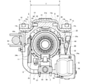
- FIG. 6 is an end view seen from the left side of FIG.
- FIG. 7 is a cross-sectional view taken along the line AA of FIG.
- FIG. 8 is a cross-sectional view taken along the line BB of FIG.
- FIG. 11 is a side view showing the steering device according to the first example of the embodiment of the present invention.
- FIG. 11A shows a state in which the column holder is moved to the rearmost side with respect to the fixing bracket
- FIG. 11B shows a state in which the upper column is moved to the rearmost side with respect to the column holder
- FIG. 11B shows the column holder. Is moved to the frontmost side with respect to the fixing bracket, and the upper column is moved to the rearmost side with respect to the column holder.
- FIG. 11C shows the column holder moved to the rearmost side with respect to the fixing bracket.
- FIG. 12 is an exploded perspective view of the steering column device according to the first example of the embodiment of the present invention.
- FIG. 13 is an exploded perspective view of the steering column device according to the first example of the embodiment of the present invention as viewed from the side opposite to FIG. 12 in the width direction.
- FIG. 14 is a side view showing the fixing bracket and the lower side telescopic actuator taken out from the steering column device according to the first example of the embodiment of the present invention.
- FIG. 15 is a perspective view showing the fixing bracket and the lower side telescopic actuator taken out from the steering column device according to the first example of the embodiment of the present invention.
- FIG. 16 is a perspective view showing a displacement bracket taken out from the steering column device according to the first example of the embodiment of the present invention.
- FIG. 17 is a diagram corresponding to FIG. 9, showing a second example of the embodiment of the present invention.
- FIG. 18 is a perspective view showing a fixed bracket, a lower side telescopic actuator, a reaction force applying device, and a linear guide taken out from the steering device according to the second example of the embodiment of the present invention.
- FIG. 19 is a perspective view showing a fixed bracket, a displacement bracket, a lower side telescopic actuator, a reaction force applying device, and a linear guide taken out from the steering device according to the second example of the embodiment of the present invention.
- the first example of the embodiment of the present invention will be described with reference to FIGS. 1 to 16.
- This example is an example in which the steering column device of the present invention is incorporated into the steering device of a steering system of a steer-by-wire system.
- the steering system 67 of the steer-by-wire system is for imparting a steering angle to the steering wheel 68 and the steering device 1 having a sensor (not shown) for measuring the steering amount of the steering wheel 68, and the pair of steering wheels 69. It is electrically connected to the steering device 70. That is, in the steering system 67 of the steer-by-wire system, the amount of operation of the steering wheel 68 by the driver is measured by the sensor of the steering device 1.
- the actuator 71 of the steering device 70 is driven, and the linear motion shafts such as the rack shaft and the screw shaft arranged in the width direction of the vehicle are displaced in the width direction of the vehicle to form a pair.
- the tie rod 72 is pushed and pulled to give a steering angle to the pair of steering wheels 69.
- the steering device 1 of this example includes a steering column device 2, a steering shaft 3, and a reaction force applying device 4.
- the front-rear direction, the vertical direction, and the width direction refer to the front-rear direction, the vertical direction, and the width direction of the vehicle with the steering device 1 attached to the vehicle.
- the steering column device 2 includes a steering column 5, a lower side telescopic actuator 6, an upper side telescopic actuator 7, and a tilt actuator 8.
- the steering column 5 includes a fixed bracket 9, a column holder 10, an upper column 11, and a linear guide 12, and is configured to have a stretchable overall length. Specifically, in the steering column 5, the fixed bracket 9 and the column holder 10 are combined in an axial relative displacement via the linear guide 12, and the column holder 10 and the upper column 11 are combined in the axial direction. The relative displacements of are combined as possible.
- the fixing bracket 9 includes a fixing plate portion 13 and a fixing side bracket portion 14.
- the fixing plate portion 13 has a rectangular shape extending in the front-rear direction when viewed from the vertical direction, and has through holes 15 penetrating in the vertical direction at two locations in the front-rear direction on both side portions in the width direction.
- the fixing bracket 9 is supported and fixed to a vehicle body (not shown) by a mounting bolt 16 inserted from below into the through hole 15 of the fixing plate portion 13. Further, as shown in FIGS. 7 to 9, the fixing plate portion 13 is bent downward from the base portion 13a arranged in the middle portion in the width direction and both ends in the width direction of the base portion 13a in the cross-sectional view seen from the front-rear direction.
- the bent portion 13b is inclined outward in the width direction toward the bottom. Further, the through hole 15 is formed in the flange portion 13c.
- the fixed side bracket portion 14 has a substantially U-shape when viewed from the front-rear direction, and is fixed to the front end portion of the fixed plate portion 13. That is, the fixed-side bracket portion 14 has a pair of fixed-side side plate portions 17a and 17b hanging downward from both end portions in the width direction of the front end portion of the fixed plate portion 13, and the fixed-side side plate portion 17a. It has a fixed-side connecting portion 18 that connects the lower ends of 17b to each other. In other words, the fixed-side connecting portion 18 is hung between the lower end portions of the pair of fixed-side side plate portions 17a and 17b.
- the column holder 10 includes a displacement bracket 19 that is supported to allow relative displacement in the axial direction (front-back direction) with respect to the fixed bracket 9, and a lower column 20 that is supported to swing vertically with respect to the displacement bracket 19. , Equipped with.
- the displacement bracket 19 includes a displacement plate portion 21, a pair of hanging plate portions 22a and 22b, and a swing support bracket portion 23.
- the displacement plate portion 21 has a rectangular shape extending in the front-rear direction when viewed from the vertical direction, and has a recess 27 on the upper surface of the front side portion. Further, as shown in FIGS. 7 to 9, the displacement plate portions 21 are connected to the thick portion 21b arranged in the middle portion in the width direction and on both sides in the width direction of the thick portion 21b in the cross-sectional view seen from the front-rear direction. It also has a thin portion 21c whose thickness is smaller than that of the thick portion 21b.
- the thick portion 21b faces the base portion 13a of the fixing plate portion 13 in the vertical direction via a gap.
- a recess 27 is formed on the upper surface of the front side portion of the thick portion 21b.
- the linear guide 12 is arranged in the recess 27.
- the thin-walled portion 21c faces the corner portion which is the connection portion between the bent portion 13b and the flange portion 13c of the fixing plate portion 13 via a slight gap.
- the pair of hanging plate portions 22a and 22b hang down from the ends on both sides in the width direction from the front side portion to the intermediate portion of the displacement plate portion 21.
- the swing support bracket portion 23 has a substantially U-shape when viewed from the front-rear direction, and is fixed to the rear end portion of the displacement plate portion 21. That is, the swing support bracket portion 23 has a pair of displacement side plate portions 24a and 24b hanging downward from both end portions in the width direction of the rear end portion of the displacement plate portion 21 and the pair of displacements. It has a displacement side connecting portion 25 that connects the lower ends of the side plate portions 24a and 24b to each other.
- the displacement side plate portion 24a on one side in the width direction (right side in FIGS. 6 to 8 and left side in FIG. 9) is a concave groove extending in the vertical direction on the inner side surface in the width direction. It has 26 (see FIG. 16).
- the displacement side connecting portion 25 has a circular hole penetrating in the vertical direction on one side portion in the width direction.
- the displacement bracket 19 is supported by the linear guide 12 so as to be relatively displaced in the axial direction with respect to the fixed bracket 9. That is, in this example, the fixed bracket 9 constitutes the first column member, and the displacement bracket 19 constitutes the second column member.
- a linear guide 12 as a low-friction sliding member having a low coefficient of friction and good sliding characteristics is arranged between the fixed bracket 9 and the displacement bracket 19.
- the linear guide 12 has a guide rail 28 having a rectangular shape extending in the axial direction (front-back direction) and a substantially U-shape when viewed from the axial direction, and the guide rail 28 is along the guide rail 28. It comprises two sliders 29, which are combined to allow axial displacement.
- the guide rail 28 is coupled and fixed to the lower surface of the base portion 13a of the fixing plate portion 13 of the fixing bracket 9 by a plurality of support bolts 30.
- each of the sliders 29 is coupled and fixed to the inside of the recess 27 of the thick portion 21b of the displacement bracket 19 by a plurality of support bolts 31.
- the displacement bracket 19 is a through hole 63 that penetrates the displacement plate portion 21 in the vertical direction at a plurality of axial directions at two locations in the width direction sandwiching the central axis of the steering column 5 in the displacement plate portion 21.
- the upper end of each of the through holes 63 is open to the bottom surface of the recess 27.
- each of the sliders 29 has screw holes 64 at two positions separated from each other in the axial direction on both side portions in the width direction of the lower surface.
- Each of the sliders 29 is supported and fixed to the inside of the recess 27 of the thick portion 21b of the displacement bracket 19 by screwing the support bolt 31 into which the through hole 63 is inserted from below into the screw hole 64.
- the displacement bracket 19 supports the relative displacement in the axial direction with respect to the fixed bracket 9.
- the linear guide 12 is arranged inside the outer peripheral surface of the lower column 20 in the width direction.
- a pair of virtual planes S extending in the vertical direction in contact with both ends in the width direction of the outer peripheral surface of the lower column 20 are shown by broken lines.
- the linear guide 12 is arranged in the region T sandwiched between the pair of virtual planes S in the width direction. Therefore, the steering column device 2 can be made more compact in the width direction as compared with the case where the low friction sliding member such as the linear guide 12 is arranged outside the outer peripheral surface of the lower column 20 in the width direction.
- the thick portion 21b of the displacement plate portion 21 is also arranged inside the outer peripheral surface of the lower column 20 in the width direction. That is, the thick portion 21b of the displacement plate portion 21 is arranged in the region T sandwiched between the pair of virtual planes S in the width direction. Therefore, the steering column device 2 can be made more compact in the width direction as compared with the case where the thick portion 21b of the displacement plate portion 21 is arranged outside the outer peripheral surface of the lower column 20 in the width direction.
- the thickness of the thick portion 21b of the displacement plate portion 21 of the displacement bracket 19 is set to be larger than the thickness of the base portion 13a of the fixed bracket 9. More specifically, the sliding direction of the linear guide 12 (front-back direction), the direction in which the linear guide 12 is restricted from being displaced by the recess 27 of the displacement plate portion 21 (width direction), and the direction perpendicular to the direction (vertical direction).
- the thickness D1 of the portion adjacent to the portion (recessed portion 27) where the linear guide 12 is arranged is the thickness d1 of the portion of the base portion 13a adjacent to the portion where the linear guide 12 is arranged. Is set larger than. As a result, the steering column device 2 can be made compact in the width direction while ensuring rigidity.
- any of a sliding linear guide, a ball circulation type linear guide, and a non-circulation roller type linear guide may be used.
- the sliding linear guide is formed by engaging the engaging protrusion formed on the slider with the rail groove formed on the guide rail.
- the ball circulation type linear guide arranges a plurality of balls so that they can roll in a load path provided between the guide rail and the slider, and inside the slider, due to the relative displacement between the guide rail and the slider.
- a circulation path is provided to return the ball that has moved to the end point of the load path to the start point of the load path.
- the non-circulating roller type linear guide is formed by rolling and contacting a plurality of rollers rotatably supported by the slider with a rolling surface formed on the guide rail.
- the illustrated linear guide 12 includes two sliders 29 (see FIG. 15). However, when the present invention is carried out, the number of sliders of the linear guide may be one or three or more.
- the lower column 20 has a substantially cylindrical shape and is supported so as to be able to swing in the vertical direction with respect to the displacement bracket 19.
- the lower column 20 has a large diameter portion 32 on the front side portion and a small diameter portion 33 having a smaller inner diameter than the large diameter portion 32 on the rear side portion.
- the lower column 20 has a slit 34 extending in the axial direction on the lower surface of the intermediate portion in the axial direction (the portion from the rear portion of the large diameter portion 32 to the front end portion of the small diameter portion 33), and is large.
- Screw holes 35a and 35b are provided on the upper surfaces of the front end of the diameter portion 32 and the front end of the small diameter portion 33, respectively.
- Screw plugs 37a and 37b, to which pads 36a and 36b made of a material having a small coefficient of friction such as polyacetal (POM) are adhesively fixed, are screwed into the screw holes 35a and 35b, respectively.
- POM polyacetal
- the lower column 20 has a rear portion thereof in the vertical direction with respect to the swing support bracket portion 23 of the displacement bracket 19 via the tilt feed screw device 38 (see FIG. 16) constituting the tilt actuator 8. Supports displacement as possible. Further, the lower column 20 pivotally supports the front side portion to the fixed side bracket portion 14 of the fixed bracket 9 supported by the vehicle body via the inner column 39 and the housing 40 of the reaction force applying device 4.
- the tilt feed screw device 38 has a screw shaft 41 having a male screw portion on the outer peripheral surface, a female screw portion screwed with the male screw portion on the inner peripheral surface, and a columnar pivot shaft on the outer peripheral surface.
- a nut 43 having a portion 42 is provided.
- the screw shaft 41 is placed in a radial rolling bearing and / Alternatively, it is rotatably supported via a bearing device 44 such as a slide bearing, and the pivot shaft portion 42 of the nut 43 is a pivot recess formed on the outer peripheral surface of the rear portion (small diameter portion 33) of the lower column 20. It is rotatably supported (bearing).
- the inner column 39 includes a cylindrical portion 45 and a flange portion 46 bent outward in the radial direction from the front end portion of the cylindrical portion 45.
- the inner column 39 is combined with the lower column 20 to allow axial relative displacement of the lower column 20.
- the pad 36a of the screw plug 37a in which the rear portion of the cylindrical portion 45 is internally fitted into the large diameter portion 32 of the lower column 20 by gap fitting and screwed into the screw hole 35a on the front side of the lower column 20 is provided. It abuts against the outer peripheral surface of the rear portion of the cylindrical portion 45.
- the inner column 39 is internally fitted to the lower column 20 so as to be relatively displaced in the axial direction of the lower column 20.
- the screw plug 37a does not directly abut on the outer peripheral surface of the cylindrical portion 45, and the pad 36a provided at the tip of the screw plug 37a abuts on the outer peripheral surface of the cylindrical portion 45, the abutting force can be easily adjusted. .. Further, the abutting force can be easily adjusted by adjusting the tightening torque of the screw plug 37a. In this way, the sliding friction force between the pad 36a and the outer peripheral surface of the cylindrical portion 45 when the inner column 39 and the lower column 20 are displaced relative to each other in the axial direction can be adjusted.
- An elastic member such as a spring may be used to adjust the abutting force of the pad 36a against the cylindrical portion 45.
- one screw hole 35a is formed on the front side of the lower column 20, and a screw plug 37a having a pad 36a is screwed into the one screw hole 35a.
- a plurality of screw holes 35a are provided.
- a screw plug 37a having a pad 36a may be screwed into each of the plurality of screw holes 35a.
- the housing 40 of the reaction force applying device 4 is supported and fixed to the inner column 39 by a fixing bolt 48 inserted from the rear side into the through hole 47 formed in the flange portion 46 of the inner column 39. Further, the housing 40 is pivotally supported with respect to the fixing bracket 9 by a pivot bolt 49 through which a through hole formed in the fixing side plate portions 17a and 17b of the fixing side bracket portion 14 is inserted.
- the upper column 11 has a substantially cylindrical shape, and is combined so as to be relatively displaced in the axial direction with respect to the column holder 10.
- the upper column 11 has a pad 36b of a screw plug 37b in which the front side portion is internally fitted into the small diameter portion 33 of the lower column 20 by gap fitting and screwed into the screw hole 35b on the rear side of the lower column 20. It abuts against the outer peripheral surface of the front side portion of the upper column 11.
- the upper column 11 is internally fitted to the lower column 20 so as to be relatively displaced in the axial direction of the lower column 20.
- the screw plug 37b does not directly abut on the outer peripheral surface of the upper column 11, and the pad 36b provided at the tip of the screw plug 37b abuts on the outer peripheral surface of the upper column 11, so that the abutting force can be adjusted. Is easy. Further, the abutting force can be easily adjusted by adjusting the tightening torque of the screw plug 37b. In this way, the sliding friction force between the pad 36b and the outer peripheral surface of the upper column 11 when the upper column 11 and the lower column 20 are displaced relative to each other in the axial direction can be adjusted.
- An elastic member such as a spring may be used to adjust the abutting force of the pad 36b against the outer peripheral surface of the upper column 11.
- one screw hole 35b is formed on the rear side of the lower column 20, and a screw plug 37b having a pad 36b is screwed into the one screw hole 35b.
- a plurality of screw holes 35b are provided.
- a screw plug 37b having a pad 36b may be screwed into each of the plurality of screw holes 35b.
- the lower side telesco actuator 6 has a lower side telesco motor 50, and the column holder 10 is displaced in the axial direction with respect to the fixed bracket 9 using the lower side telesco motor 50 as a drive source.
- the lower side telesco actuator 6 constitutes a telesco actuator
- the lower side telesco motor 50 constitutes a telesco motor.
- the lower side telesco actuator 6 further includes a lower side feed screw device 51 for converting the rotational motion of the output shaft of the lower side telesco motor 50 into a linear motion.
- the lower side feed screw device 51 has a male screw portion on the outer peripheral surface, a screw shaft 52 rotationally driven by the lower side telescopic motor 50, and a nut having a female screw portion screwed with the male screw portion on the inner peripheral surface. 53 and.
- the screw shaft 52 is rotatably supported by the fixing bracket 9, and the nut 53 is supported and fixed to the displacement bracket 19 of the column holder 10.
- the screw shaft 52 is placed outside the width direction of the fixed side plate portion 17b on the other side in the width direction (left side in FIGS. 6 to 8 and right side in FIG. 9) of the fixed side bracket portion 14 constituting the fixed bracket 9. It is rotatably fixed to the side surface (other side surface in the width direction), and the nut 53 is supported and fixed to the outer surface in the width direction of the hanging plate portion 22b on the other side in the width direction of the displacement bracket 19. Further, the lower side telescopic motor 50 is supported and fixed to the fixed side bracket portion 14.
- the displacement bracket 19 Is displaced with respect to the fixed bracket 9 in the axial direction of the fixed bracket 9, that is, in the front-rear direction.
- the upper side telesco actuator 7 has an upper side telesco motor 54, and the upper column 11 is displaced in the axial direction with respect to the column holder 10 by using the upper side telesco motor 54 as a drive source.
- the upper telesco actuator 7 further includes an upper feed screw device 55 for converting the rotational motion of the output shaft of the upper telesco motor 54 into a linear motion.
- the upper side feed screw device 55 has a male screw portion on the outer peripheral surface, a screw shaft 56 rotationally driven by the upper telesco motor 54, and a nut having a female screw portion screwed with the male screw portion on the inner peripheral surface. 57 and.
- the screw shaft 56 is supported only rotatably with respect to the lower column 20 of the column holder 10, and the nut 57 is supported and fixed to the upper column 11. More specifically, the screw shaft 56 is rotatably supported only on the lower surface of the front side portion of the large diameter portion 32 of the lower column 20, and the nut 57 is supported and fixed to the lower surface of the front side portion of the upper column 11. is doing. Further, the upper telesco motor 54 is supported and fixed to the lower column 20.
- the tilt actuator 8 has a tilt motor 58 and a tilt feed screw device 38.
- the tilt actuator 8 rotationally drives the screw shaft 41 of the tilt feed screw device 38 by the tilt motor 58 via a reduction mechanism such as a worm reducer, and moves the nut 43 in the vertical direction along the screw shaft 41.
- a reduction mechanism such as a worm reducer
- the steering shaft 3 is a combination of the inner shaft 59 and the outer shaft 60, which enables relative displacement in the axial direction and makes relative rotation impossible.
- the steering shaft 3 is formed by spline-engaging the rear portion of the front inner shaft 59 and the front portion of the rear outer shaft 60.
- the steering shaft 3 is rotatably supported inside the steering column 5 of the steering column device 2 in the radial direction. Specifically, the front end of the outer shaft 60 is rotatably supported by the radial rolling bearing 61a on the front end of the upper column 11, and the rear end of the outer shaft 60 is supported by the upper column 11. A radial rolling bearing 61b rotatably supports the rear end portion. Therefore, the steering shaft 3 expands and contracts together with the steering column 5.
- the steering wheel 68 is supported at the rear end of the steering shaft 3, that is, the rear end of the outer shaft 60. Further, a reaction force applying device 4 for applying an operating reaction force to the steering wheel 68 is connected to the front end of the steering shaft 3, that is, the front end of the inner shaft 59.
- the reaction force applying device 4 includes a housing 40, a reaction force applying motor (not shown), and a speed reducer.
- the reaction force applying device 4 drives the reaction force applying motor when the steering wheel 68 is operated by the driver, and the torque of the reaction force applying motor is increased by the speed reducer housed inside the housing 40. Therefore, it is applied to the steering shaft 3.
- an operating reaction force is applied to the steering wheel 68.
- the magnitude of the reaction force applied to the steering wheel 68 is determined according to the steering angle of the steering wheel 68 acquired by the sensor, the torque applied to the steering shaft 3, and the like.
- the reducer is composed of, for example, a worm reducer.
- the column holder 10 (displacement bracket 19) is axially oriented with respect to the fixed bracket 9 based on the energization of the lower side telesco motor 50.
- the upper column 11 is displaced relative to the column holder 10 (lower column 20) in the axial direction (front-back direction) based on the relative displacement in the (front-back direction) and / or the energization of the upper-side telesco motor 54.
- the displacement bracket 19 is generated by energizing the lower-side telesco motor 50 and rotationally driving the screw shaft 52 of the lower-side feed screw device 51 by the lower-side telesco motor 50 to displace the nut 53 in the front-rear direction.
- the upper side telesco motor 54 is energized, and the upper side telesco motor 54 rotationally drives the screw shaft 56 of the upper side feed screw device 55 to displace the nut 57 in the front-rear direction.
- the column 11 is displaced with respect to the lower column 20 in the axial direction of the lower column 20, that is, in the front-rear direction.
- the total length of the steering column 5 is expanded and contracted, and the total length of the steering shaft 3 is expanded and contracted to adjust the front-rear position of the steering wheel 68.
- the energization of the lower side telesco motor 50 and / or the upper side telesco motor 54 is stopped.
- the rear portion of the lower column 20 is displaced in the vertical direction with respect to the displacement bracket 19 based on the energization of the tilt motor 58. That is, by energizing the tilt motor 58 and rotationally driving the screw shaft 41 of the tilt feed screw device 38 by the tilt motor 58 to displace the nut 43 in the vertical direction, the lower column 20 is pivotally bolted. The rear portion of the lower column 20 is displaced in the vertical direction while swinging around the 49. As a result, the rear end of the steering shaft 3 rotatably supported inward in the radial direction of the steering column 5 is displaced in the vertical direction, and the vertical position of the steering wheel 68 is adjusted. After adjusting the vertical position of the steering wheel 68 to a desired position, the energization of the tilt motor 58 is stopped.
- the adjustment of the front-rear position of the steering wheel 68 and the adjustment of the up-down position can be performed at the same time, or can be performed independently (back and forth in time).
- the steering column 5 is combined with the fixed bracket 9 and the column holder 10 so as to enable relative displacement in the axial direction, and the column holder 10 and the upper column 11 are combined so as to enable relative displacement in the axial direction. It is configured. That is, the steering column 5 has a two-stage telescopic structure. Therefore, while ensuring a sufficient amount of expansion and contraction of the entire length of the steering column 5, the axial dimensions of the screw shaft 52 of the lower side feed screw device 51 and the screw shaft 56 of the upper side feed screw device 55 become excessive. Can be prevented.
- the column holder 10 is displaced in the axial direction with respect to the fixed bracket 9 by the lower side telescopic actuator 6, and the upper column 11 is attached to the column holder 10 by the upper side telescopic actuator 7. It is configured to be displaced in the axial direction. Therefore, even if one of the lower side telesco actuator 6 and the upper side telesco actuator 7 has a failure such as a failure, the other actuator adjusts the front-rear position of the steering wheel 68. be able to.
- the column holder 10 is energized by simultaneously energizing the lower side telescopic motor 50 of the lower side telescopic actuator 6 and the upper side telescopic motor 54 of the upper side telescopic actuator 7.
- the fixing bracket 9 is displaced in the axial direction
- the upper column 11 can be displaced in the axial direction with respect to the column holder 10. Therefore, it is easy to increase the expansion / contraction speed of the steering column 5 as compared with the structure in which the entire length of the steering column is expanded / contracted by one electric motor.
- the fixed bracket 9 and the column holder 10 are combined via a linear guide 12 having high component accuracy and assembly accuracy. Therefore, it is possible to secure the support rigidity of the column holder 10 with respect to the fixed bracket 9 and reduce the resistance (displacement resistance) of the column holder 10 to be displaced in the axial direction with respect to the fixed bracket 9 at a high level. Further, by reducing the displacement resistance of the column holder 10, the lower side telescopic actuator 6 for vertically displaces the column holder 10 with respect to the fixed bracket 9 can be miniaturized, and the column holder 10 can be miniaturized. It is possible to suppress the operating noise when the is displaced relative to the fixed bracket 9 in the axial direction.
- the expansion / contraction speed of the steering column 5 can be increased.
- the amount of adjustment of the front-rear position of the steering wheel 68 is large, such as when the steering wheel 68 is stored inside the dashboard or when the steering wheel 68 stored inside the dashboard is deployed. , The effect of increasing the expansion / contraction speed of the steering column 5 can be remarkably obtained.
- the steering wheel 68 is steered from the steering wheel 68 when the driver gets on and off the vehicle. It is possible to sufficiently secure the rigidity against the downward force applied to the column 5 and the lateral force applied to the steering column 5 from the steering wheel 68 when traveling on a curve.
- the steering device 1 of this example when adjusting the front-rear position of the steering wheel 68, for example, after the fixed bracket 9 is largely displaced with respect to the column holder 10 at high speed in the axial direction, the column with respect to the fixed bracket 9 is used.
- the front-rear position of the steering wheel 68 can be adjusted to a desired position.
- the guide rail 28 of the linear guide 12 is coupled and fixed to the lower surface of the fixing plate portion 13 of the fixing bracket 9 by a plurality of support bolts 30, and the slider 29 is connected and fixed to the displacement plate of the displacement bracket 19. It is coupled and fixed to the upper surface of the portion 21 by a plurality of support bolts 31. Since the linear guide 12 has high component accuracy and assembly accuracy, the column holder 10 is displaced in the axial direction with respect to the fixed bracket 9 after the fixing bracket 9 and the column holder 10 are combined via the linear guide 12. There is no need to adjust the resistance (displacement resistance). In short, according to the steering column device 2 of this example, even when the steering column 5 has a two-stage telescopic structure, it can be easily configured and the assembly cost can be kept low.
- the linear guide 12 is arranged in the upper portion of the portion between the fixed bracket 9 and the displacement bracket 19, but in the case of carrying out the present invention, the linear guide is provided between the fixed bracket and the displacement bracket. It can also be placed in the lower part of the intervening part.
- the linear guides can be arranged on both sides in the width direction of the portion between the fixed bracket and the displacement bracket. In this case, one linear guide is arranged on both sides in the width direction of the portion between the fixed bracket and the displacement bracket.
- the fixed bracket 9 and the column holder 10 are combined via the linear guide 12, but instead of or in addition to this, the column holder (lower column) and the upper column are combined. Can also be combined via a linear guide.
- the present invention can also be applied to a steering column device having only a telesco mechanism. Further, in this example, the case where the steering column device of the present invention is applied to the steering device of the steering system of the steer-by-wire system has been described, but the steering column device of the present invention is not limited to this, and the steering column device of the present invention is not limited to this. It can also be applied to a mechanical steering system in which the end is mechanically connected to the input shaft (pinion shaft) of the steering gear unit via a universal joint or an intermediate shaft. The mechanical steering system can be provided with an assist device for reducing the force required for the driver to operate the steering wheel. That is, the steering column device of the present invention can be applied to a power steering system such as an electric power steering system.
- a power steering system such as an electric power steering system.
- the steering column 5 of this example has a two-stage telescopic structure
- the present invention can also be applied to a steering column device in which the steering column has a one-stage telescopic structure.
- FIGS. 17 to 19 A second example of the embodiment of the present invention will be described with reference to FIGS. 17 to 19.
- the support structure of the slider 29a constituting the linear guide 12a with respect to the displacement bracket 19a is different from that of the steering column device 2 of the first embodiment.
- the position of the support bolt 31a for supporting the slider 29a with respect to the displacement bracket 19a is positioned outside in the width direction from the first example of the embodiment.
- the displacement bracket 19a has through holes 63a that penetrate the displacement plate portion 21 in the vertical direction at a plurality of axial directions at two locations in the width direction sandwiching the central axis of the steering column 5a in the displacement plate portion 21. ..
- each of the through holes 63a is formed at a plurality of positions in the axial direction of the displacement plate portion 21 at two positions in the width direction sandwiching the portion where the recess 27 is formed.
- the slider 29a of the linear guide 12a has a substantially rectangular columnar shape, and has a main body portion 65 having an engaging portion on the upper surface thereof that is engaged with the guide rail 28 so as to be axially displaced along the guide rail 28.
- a pair of flange portions 66 projecting outward in the width direction from the upper ends of both side surfaces in the width direction of the main body portion 65 are provided.
- the slider 29a has screw holes 64a at a plurality of axial directions on the lower surface of each of the flange portions 66.
- the slider 29a has a support bolt 31a formed in the flange portion 66 through which the through hole 63a is inserted from below in a state where the lower portion of the main body portion 65 is engaged (arranged) inside the recess 27 of the displacement bracket 19a. By screwing into the screw hole 64a, it is supported and fixed to the upper surface of the displacement bracket 19a.
- the position of the support bolt 31a for supporting the slider 29a with respect to the displacement bracket 19a is positioned outside in the width direction from the first example of the embodiment. Therefore, it is easy to secure the support rigidity of the slider 29a with respect to the displacement bracket 19a. Further, it is possible to sufficiently secure a vertical distance (clearance) between the head of the support bolt 31a and the upper surface of the lower column 20. As a result, a sufficient amount of swingable amount of the lower column 20 in the vertical direction (adjustable amount of the vertical position of the steering wheel) with respect to the displacement bracket 19a can be sufficiently secured.
- the composition and action / effect of other parts are the same as those of the first example of the embodiment.
- FIG. 20 is a cross-sectional view showing the steering device of the present embodiment, and is a view corresponding to FIG. 7.
- a rolling member 80 as a low friction sliding member is arranged in a portion between the fixed bracket 9 and the displacement bracket 19.
- the rolling member 80 is exemplified by a spherical or columnar rolling element made of steel. In the illustrated example, a spherical rolling element is applied.
- Grooves 82 and 81 on which the rolling member 80 can be arranged are formed on the facing surfaces of the pair of bent portions 13b and the pair of thick-walled portions 21b, respectively. Then, the rolling member 80 is arranged between the groove portions 82 and 81.
- the number of rolling members 80 is not particularly limited, and a plurality of rolling members 80 may be arranged in the front-rear direction.
- the displacement bracket 19 is supported by the rolling member 80 so as to be relatively displaced in the axial direction with respect to the fixed bracket 9.
- This embodiment is the same as the linear guides 12 and 12a of the first and second examples of the embodiment in that the rolling mechanism is used as the low friction sliding member.
- the pair of rolling members 80 are arranged and fixed at two locations (a pair of bent portions 13b) in the width direction of the fixing bracket 9 so as to face each other in the width direction with the thick portion 21b interposed therebetween. Since the bracket 9 and the displacement bracket 19 have a structure having a tightening allowance in the width direction and the vertical direction, movements other than relative movement in the axial direction can be restricted.
- the number of parts is reduced and the structure can be simplified as compared with the case where the linear guides 12 and 12a are used as in the first and second examples of the embodiment, so that the linear guide can be simplified. It is possible to reduce the cost while having the same characteristics as those of 12 and 12a.
- the pair of rolling members 80 are arranged inside the outer peripheral surface of the lower column 20 in the width direction.
- a pair of virtual planes S extending in the vertical direction in contact with both ends in the width direction of the outer peripheral surface of the lower column 20 are shown by broken lines.
- a pair of rolling members 80 are arranged in the region T sandwiched between the pair of virtual planes S in the width direction. Therefore, the steering column device can be made more compact in the width direction as compared with the case where the pair of rolling members 80 are arranged outside the outer peripheral surface of the lower column 20 in the width direction.
- the thickness of the thick portion 21b of the displacement plate portion 21 of the displacement bracket 19 is set to be larger than the thickness of the bent portion 13b of the fixed bracket 9.
- the thickness D2 of the portion of the thick portion 21b adjacent to the portion where the rolling member 80 is arranged is the portion of the bent portion 13b adjacent to the portion (groove portion 81) where the rolling member 80 is arranged.
- the thickness is set to be larger than d2.
- the fixing bracket 9 and the column holder 10 are combined via the rolling member 80, but instead of or in addition to this, the column holder (lower column) and the upper column are used. Can also be combined via the rolling member 80.
- FIG. 21 is a cross-sectional view showing the steering device of the present embodiment, and is a diagram corresponding to FIG. 7.
- a sliding member 90 as a low friction sliding member is arranged in a portion between the fixed bracket 9 and the displacement bracket 19.
- the sliding member 90 of this example has a rectangular cross section and a rectangular parallelepiped shape extending in the front-rear direction, but the shape is not limited.
- the sliding member 90 is fixed to one of the fixed bracket 9 and the displacement bracket 19, and slides while being guided to the other to enable relative movement of the fixed bracket 9 and the displacement bracket 19 in the axial direction.
- the sliding member 90 is fixed to either one of the groove portions 92 and 91 by fitting, welding, adhesion, or the like, and can slide while being guided to the other.
- a self-lubricating resin such as PTFE (polytetrafluoroethylene resin) for the sliding member 90, friction during operation can be reduced.
- a material other than the self-lubricating resin may be appropriately selected and adopted.
- the displacement bracket 19 is guided and supported by the sliding member 90 so as to be relatively displaced in the axial direction with respect to the fixed bracket 9.
- the pair of sliding members 90 are arranged at two locations (a pair of bent portions 13b) in the width direction of the fixing bracket 9 so as to face each other in the width direction with the thick portion 21b interposed therebetween. Since the 9 and the displacement bracket 19 have a structure having a tightening allowance in the width direction and the vertical direction, movements other than the relative movement in the axial direction can be regulated. Further, according to the present embodiment, the number of parts is reduced and the structure can be simplified as compared with the case where the linear guides 12 and 12a are used as in the first and second examples of the embodiment, so that the linear guide can be simplified. It is possible to reduce the cost while having the same characteristics as those of 12 and 12a.
- the pair of sliding members 90 are arranged inside the outer peripheral surface of the lower column 20 in the width direction.
- a pair of virtual planes S extending in the vertical direction in contact with both ends in the width direction of the outer peripheral surface of the lower column 20 are shown by broken lines.
- a pair of sliding members 90 are arranged in the region T sandwiched between the pair of virtual planes S in the width direction. Therefore, the steering column device 2 can be made more compact in the width direction than when the pair of sliding members 90 are arranged outside the outer peripheral surface of the lower column 20 in the width direction.
- the thickness of the thick portion 21b of the displacement plate portion 21 of the displacement bracket 19 is set to be larger than the thickness of the bent portion 13b of the fixed bracket 9.
- the thickness D3 of the portion of the thick portion 21b adjacent to the portion where the sliding member 90 is arranged is the portion of the bent portion 13b adjacent to the portion where the sliding member 90 is arranged (groove portion 91).
- the thickness is set to be larger than d3.
- the fixing bracket 9 and the column holder 10 are combined via the sliding member 90, but instead of or in addition to this, the column holder (lower column) and the upper column are used. Can also be combined via the sliding member 90.
Landscapes
- Engineering & Computer Science (AREA)
- Chemical & Material Sciences (AREA)
- Combustion & Propulsion (AREA)
- Transportation (AREA)
- Mechanical Engineering (AREA)
- Steering Controls (AREA)
Priority Applications (4)
| Application Number | Priority Date | Filing Date | Title |
|---|---|---|---|
| EP21861767.8A EP4206058A4 (en) | 2020-08-31 | 2021-08-31 | Steering column device |
| US18/043,170 US12151738B2 (en) | 2020-08-31 | 2021-08-31 | Steering column device |
| CN202180052756.9A CN115884912A (zh) | 2020-08-31 | 2021-08-31 | 转向柱装置 |
| JP2022545763A JP7492014B2 (ja) | 2020-08-31 | 2021-08-31 | ステアリングコラム装置 |
Applications Claiming Priority (2)
| Application Number | Priority Date | Filing Date | Title |
|---|---|---|---|
| JP2020-145213 | 2020-08-31 | ||
| JP2020145213 | 2020-08-31 |
Publications (1)
| Publication Number | Publication Date |
|---|---|
| WO2022045346A1 true WO2022045346A1 (ja) | 2022-03-03 |
Family
ID=80353506
Family Applications (1)
| Application Number | Title | Priority Date | Filing Date |
|---|---|---|---|
| PCT/JP2021/031858 Ceased WO2022045346A1 (ja) | 2020-08-31 | 2021-08-31 | ステアリングコラム装置 |
Country Status (5)
| Country | Link |
|---|---|
| US (1) | US12151738B2 (https=) |
| EP (1) | EP4206058A4 (https=) |
| JP (1) | JP7492014B2 (https=) |
| CN (1) | CN115884912A (https=) |
| WO (1) | WO2022045346A1 (https=) |
Cited By (6)
| Publication number | Priority date | Publication date | Assignee | Title |
|---|---|---|---|---|
| US20230192172A1 (en) * | 2020-05-18 | 2023-06-22 | Robert Bosch Automotive Steering Vendome Sas | Steering Column Equipped with a Device for Detecting the Forces Applied to the Steering Wheel |
| WO2024088473A1 (de) * | 2022-10-28 | 2024-05-02 | Schaeffler Technologies AG & Co. KG | Verstelleinheit einer lenksäule |
| WO2025004208A1 (ja) * | 2023-06-28 | 2025-01-02 | 株式会社ジェイテクト | ステアリング装置 |
| US20250276731A1 (en) * | 2024-03-01 | 2025-09-04 | Ferrari S.P.A. | Steering system for motor vehicle and motor vehicle comprising the same |
| US12441387B1 (en) * | 2024-09-10 | 2025-10-14 | Steering Solutions Ip Holding Corporation | Rake adjustment assembly for vehicle steering system |
| EP4538148A4 (en) * | 2022-09-06 | 2025-10-15 | Zhejiang Zeekr Intelligent Tech Co Ltd | STEERING COLUMN AND VEHICLE |
Families Citing this family (1)
| Publication number | Priority date | Publication date | Assignee | Title |
|---|---|---|---|---|
| CN115884912A (zh) * | 2020-08-31 | 2023-03-31 | 日本精工株式会社 | 转向柱装置 |
Citations (7)
| Publication number | Priority date | Publication date | Assignee | Title |
|---|---|---|---|---|
| JP2011178304A (ja) * | 2010-03-02 | 2011-09-15 | Nsk Ltd | ステアリング装置 |
| JP2015227166A (ja) * | 2012-05-25 | 2015-12-17 | 日本精工株式会社 | 電動ステアリングホイールの位置調節装置 |
| US20170029009A1 (en) * | 2015-07-31 | 2017-02-02 | Steering Solutions Ip Holding Corporation | Retractable steering column with dual actuators |
| JP2017081215A (ja) * | 2015-10-23 | 2017-05-18 | 富士機工株式会社 | ステアリングコラム装置 |
| US20190111960A1 (en) * | 2017-10-17 | 2019-04-18 | Steering Solutions Ip Holding Corporation | Stowable steering column apparatus |
| US20190210632A1 (en) | 2018-01-08 | 2019-07-11 | Steering Solutions Ip Holding Corporation | Telescoping steering column |
| JP2020145213A (ja) | 2019-03-04 | 2020-09-10 | 株式会社日立製作所 | 静止誘導電器用鉄心 |
Family Cites Families (49)
| Publication number | Priority date | Publication date | Assignee | Title |
|---|---|---|---|---|
| US5737971A (en) | 1996-08-05 | 1998-04-14 | General Motors Corporation | Motor vehicle steering column |
| US20030172765A1 (en) * | 2000-04-20 | 2003-09-18 | Roland Heiml | Adjusting and fixing device for a steering shaft, whose height and/or length can be adjusted |
| US20060207378A1 (en) * | 2005-03-17 | 2006-09-21 | Delphi Technologies, Inc. | Mounting structure for steering column |
| JP5279741B2 (ja) * | 2009-03-30 | 2013-09-04 | 株式会社山田製作所 | ステアリング装置 |
| JP5620841B2 (ja) * | 2011-02-04 | 2014-11-05 | 株式会社山田製作所 | ステアリング装置 |
| US8997602B2 (en) * | 2011-12-21 | 2015-04-07 | Jtekt Corporation | Position adjustable steering device |
| CN105473418B (zh) * | 2013-10-30 | 2017-08-08 | 日本精工株式会社 | 转向装置 |
| KR101604263B1 (ko) | 2014-12-24 | 2016-03-17 | 남양공업주식회사 | 차량의 스티어링 컬럼 장치 |
| DE102015000029A1 (de) * | 2015-01-08 | 2016-07-14 | Thyssenkrupp Ag | Lenksäule mit adaptierbarer Schwenklagerung |
| JP6403336B2 (ja) * | 2015-04-21 | 2018-10-10 | 株式会社ジェイテクト | ステアリング装置 |
| JP2016203911A (ja) * | 2015-04-27 | 2016-12-08 | 株式会社山田製作所 | ステアリング装置 |
| JP6142968B1 (ja) * | 2015-10-21 | 2017-06-07 | 日本精工株式会社 | テレスコピックステアリングコラム及びステアリング装置 |
| US9744983B2 (en) * | 2015-12-18 | 2017-08-29 | Steering Solutions Ip Holding Corporation | Steering column assembly |
| JP6635297B2 (ja) * | 2016-02-19 | 2020-01-22 | 株式会社ジェイテクト | ステアリング装置 |
| US11040737B2 (en) * | 2016-02-19 | 2021-06-22 | Nsk Americas, Inc. | Guidance and limiting unit subassembly for a steering column assembly |
| WO2017158720A1 (ja) * | 2016-03-15 | 2017-09-21 | 日本精工株式会社 | ステアリング装置 |
| JP6702418B2 (ja) * | 2016-07-19 | 2020-06-03 | 日本精工株式会社 | ステアリング装置 |
| GB201616323D0 (en) * | 2016-09-26 | 2016-11-09 | Trw Limited | A steering column assembly |
| JP6799782B2 (ja) * | 2017-02-13 | 2020-12-16 | 株式会社ジェイテクト | ステアリング装置 |
| JP6635226B2 (ja) * | 2017-03-27 | 2020-01-22 | 日本精工株式会社 | ステアリング装置 |
| KR102274121B1 (ko) * | 2017-04-03 | 2021-07-06 | 현대자동차주식회사 | 자동차용 전동식 스티어링 컬럼 장치 |
| JP6777229B2 (ja) * | 2017-06-14 | 2020-10-28 | 日本精工株式会社 | ステアリングコラム装置 |
| JP6905918B2 (ja) * | 2017-11-17 | 2021-07-21 | 株式会社山田製作所 | ステアリング装置 |
| FR3078940B1 (fr) * | 2018-03-16 | 2021-06-18 | Jtekt Europe Sas | Colonne de direction comportant un dispositif de blocage en rotation actionne par une motorisation |
| WO2019189471A1 (ja) * | 2018-03-27 | 2019-10-03 | 日本精工株式会社 | ステアリング装置 |
| DE102018204735A1 (de) * | 2018-03-28 | 2018-10-11 | Thyssenkrupp Ag | Lenksäule für ein Kraftfahrzeug |
| US11001292B2 (en) * | 2018-04-02 | 2021-05-11 | Steering Solutions Ip Holding Corporation | Energy absorbing assembly of a telescoping steering column |
| JP7089975B2 (ja) * | 2018-07-31 | 2022-06-23 | 株式会社山田製作所 | ステアリング装置 |
| JP7089974B2 (ja) * | 2018-07-31 | 2022-06-23 | 株式会社山田製作所 | ステアリング装置 |
| JP7096740B2 (ja) * | 2018-08-30 | 2022-07-06 | 株式会社山田製作所 | ステアリング装置 |
| DE102018122767A1 (de) * | 2018-09-17 | 2020-03-19 | Thyssenkrupp Ag | Lenksäule und Steer-by-Wire Lenksystem |
| JP7371636B2 (ja) * | 2018-09-19 | 2023-10-31 | 日本精工株式会社 | ブラケット及びステアリング装置 |
| DE102018218243A1 (de) * | 2018-10-24 | 2020-04-30 | Thyssenkrupp Ag | Lenksäule für ein Kraftfahrzeug |
| GB2579372B (en) * | 2018-11-29 | 2022-08-24 | Trw Ltd | Retractable steer-by-wire steering column |
| KR102728273B1 (ko) * | 2018-12-14 | 2024-11-11 | 에이치엘만도 주식회사 | 자동차의 조향컬럼 |
| JP7400244B2 (ja) * | 2019-07-29 | 2023-12-19 | 株式会社ジェイテクト | ステアリング装置 |
| GB2586811B (en) * | 2019-09-03 | 2023-08-30 | Zf Automotive Uk Ltd | Steering column assembly for a vehicle |
| DE102020202196A1 (de) * | 2020-02-20 | 2021-08-26 | Thyssenkrupp Ag | Verstellantrieb für eine Lenksäule und Lenksäule für ein Kraftfahrzeug |
| US11891115B2 (en) * | 2020-03-27 | 2024-02-06 | Yamada Manufacturing Co., Ltd. | Steering device |
| DE112021001890T5 (de) * | 2020-03-27 | 2023-02-02 | Yamada Manufacturing Co., Ltd. | Lenkvorrichtung |
| WO2021224200A1 (de) * | 2020-05-07 | 2021-11-11 | Thyssenkrupp Presta Ag | Lenksäule für ein kraftfahrzeug |
| US11305807B2 (en) * | 2020-08-25 | 2022-04-19 | Thyssenkrupp Presta Ag | Vehicle steering column |
| CN115884912A (zh) * | 2020-08-31 | 2023-03-31 | 日本精工株式会社 | 转向柱装置 |
| DE112021005442T5 (de) * | 2020-12-24 | 2023-08-24 | Nsk Ltd. | Lenksäulenvorrichtung |
| KR20220122012A (ko) * | 2021-02-26 | 2022-09-02 | 현대자동차주식회사 | 자동차용 폴더블 스티어링 시스템 |
| DE102022104146A1 (de) * | 2021-03-19 | 2022-09-22 | Yamada Manufacturing Co., Ltd. | Lenkvorrichtung |
| KR102779333B1 (ko) * | 2021-12-08 | 2025-03-11 | 에이치엘만도 주식회사 | 전동식 스티어링 컬럼 |
| EP4230502B1 (de) * | 2022-02-22 | 2025-01-29 | thyssenkrupp Presta Aktiengesellschaft | Verstellantrieb für eine lenksäule und lenksäule für ein kraftfahrzeug |
| BE1030669B1 (de) * | 2022-06-30 | 2024-01-30 | Thyssenkrupp Presta Ag | Lenksäule für ein Kraftfahrzeug |
-
2021
- 2021-08-31 CN CN202180052756.9A patent/CN115884912A/zh active Pending
- 2021-08-31 US US18/043,170 patent/US12151738B2/en active Active
- 2021-08-31 EP EP21861767.8A patent/EP4206058A4/en active Pending
- 2021-08-31 JP JP2022545763A patent/JP7492014B2/ja active Active
- 2021-08-31 WO PCT/JP2021/031858 patent/WO2022045346A1/ja not_active Ceased
Patent Citations (7)
| Publication number | Priority date | Publication date | Assignee | Title |
|---|---|---|---|---|
| JP2011178304A (ja) * | 2010-03-02 | 2011-09-15 | Nsk Ltd | ステアリング装置 |
| JP2015227166A (ja) * | 2012-05-25 | 2015-12-17 | 日本精工株式会社 | 電動ステアリングホイールの位置調節装置 |
| US20170029009A1 (en) * | 2015-07-31 | 2017-02-02 | Steering Solutions Ip Holding Corporation | Retractable steering column with dual actuators |
| JP2017081215A (ja) * | 2015-10-23 | 2017-05-18 | 富士機工株式会社 | ステアリングコラム装置 |
| US20190111960A1 (en) * | 2017-10-17 | 2019-04-18 | Steering Solutions Ip Holding Corporation | Stowable steering column apparatus |
| US20190210632A1 (en) | 2018-01-08 | 2019-07-11 | Steering Solutions Ip Holding Corporation | Telescoping steering column |
| JP2020145213A (ja) | 2019-03-04 | 2020-09-10 | 株式会社日立製作所 | 静止誘導電器用鉄心 |
Non-Patent Citations (1)
| Title |
|---|
| See also references of EP4206058A4 |
Cited By (8)
| Publication number | Priority date | Publication date | Assignee | Title |
|---|---|---|---|---|
| US20230192172A1 (en) * | 2020-05-18 | 2023-06-22 | Robert Bosch Automotive Steering Vendome Sas | Steering Column Equipped with a Device for Detecting the Forces Applied to the Steering Wheel |
| EP4538148A4 (en) * | 2022-09-06 | 2025-10-15 | Zhejiang Zeekr Intelligent Tech Co Ltd | STEERING COLUMN AND VEHICLE |
| WO2024088473A1 (de) * | 2022-10-28 | 2024-05-02 | Schaeffler Technologies AG & Co. KG | Verstelleinheit einer lenksäule |
| DE102023110003A1 (de) * | 2022-10-28 | 2024-05-08 | Schaeffler Technologies AG & Co. KG | Verstelleinheit einer Lenksäule |
| DE102023110003B4 (de) * | 2022-10-28 | 2025-04-30 | Schaeffler Technologies AG & Co. KG | Verstelleinheit einer Lenksäule |
| WO2025004208A1 (ja) * | 2023-06-28 | 2025-01-02 | 株式会社ジェイテクト | ステアリング装置 |
| US20250276731A1 (en) * | 2024-03-01 | 2025-09-04 | Ferrari S.P.A. | Steering system for motor vehicle and motor vehicle comprising the same |
| US12441387B1 (en) * | 2024-09-10 | 2025-10-14 | Steering Solutions Ip Holding Corporation | Rake adjustment assembly for vehicle steering system |
Also Published As
| Publication number | Publication date |
|---|---|
| US12151738B2 (en) | 2024-11-26 |
| US20230311973A1 (en) | 2023-10-05 |
| JPWO2022045346A1 (https=) | 2022-03-03 |
| CN115884912A (zh) | 2023-03-31 |
| EP4206058A1 (en) | 2023-07-05 |
| JP7492014B2 (ja) | 2024-05-28 |
| EP4206058A4 (en) | 2024-10-16 |
Similar Documents
| Publication | Publication Date | Title |
|---|---|---|
| WO2022045346A1 (ja) | ステアリングコラム装置 | |
| CN103998323B (zh) | 转向盘的电动位置调节装置 | |
| US5265691A (en) | Rack-and-pinion steering apparatus | |
| JP5076908B2 (ja) | ステアリングコラム装置 | |
| US20080079253A1 (en) | Telescopic adjusting electric power steering apparatus | |
| JP5233671B2 (ja) | チルト式ステアリング装置 | |
| WO2003078234A1 (en) | Electric steering column device | |
| US20090260468A1 (en) | Steering device and movement converting device used therefor | |
| US20120186897A1 (en) | Toothed-Rack Steering Gear, and Servo Steering System Equipped With The Same | |
| JP2010083392A (ja) | 電動式テレスコピックステアリング装置 | |
| CN114715261A (zh) | 用于机动车辆的转向系统 | |
| JP2012245810A (ja) | ラック軸支持装置および車両用操舵装置 | |
| US5248009A (en) | Vehicle rear wheels steering apparatus | |
| JP6994405B2 (ja) | ステアリング装置 | |
| CN117622300A (zh) | 线控转向车轮致动器滚珠丝杠防旋转机构 | |
| JP2007203947A (ja) | 電動式パワーステアリング装置用ウォーム減速機及びこれを組み込んだ電動式パワーステアリング装置 | |
| JP5224525B2 (ja) | 電動パワーステアリング装置 | |
| JP2008024229A (ja) | 電動テレスコ調整式ステアリング装置 | |
| JP2023010104A (ja) | 操舵装置及び運転切替制御装置 | |
| EP1944217B1 (en) | Center-takeoff rack-and-pinion steering apparatus | |
| JP7172865B2 (ja) | 転舵装置 | |
| JP2008296752A (ja) | 電動テレスコ調整式ステアリング装置 | |
| KR102524799B1 (ko) | 정밀 작동 가능한 자동차용 틸팅-텔레스코픽 스티어링 컬럼 | |
| JP2009062031A (ja) | 電動テレスコ調整式ステアリング装置 | |
| JP2008265420A (ja) | 位置調整式ステアリング装置 |
Legal Events
| Date | Code | Title | Description |
|---|---|---|---|
| 121 | Ep: the epo has been informed by wipo that ep was designated in this application |
Ref document number: 21861767 Country of ref document: EP Kind code of ref document: A1 |
|
| ENP | Entry into the national phase |
Ref document number: 2022545763 Country of ref document: JP Kind code of ref document: A |
|
| NENP | Non-entry into the national phase |
Ref country code: DE |
|
| ENP | Entry into the national phase |
Ref document number: 2021861767 Country of ref document: EP Effective date: 20230331 |