WO2022045346A1 - Steering column device - Google Patents
Steering column device Download PDFInfo
- Publication number
- WO2022045346A1 WO2022045346A1 PCT/JP2021/031858 JP2021031858W WO2022045346A1 WO 2022045346 A1 WO2022045346 A1 WO 2022045346A1 JP 2021031858 W JP2021031858 W JP 2021031858W WO 2022045346 A1 WO2022045346 A1 WO 2022045346A1
- Authority
- WO
- WIPO (PCT)
- Prior art keywords
- column
- bracket
- displacement
- steering column
- steering
- Prior art date
Links
Images


Classifications
-
- B—PERFORMING OPERATIONS; TRANSPORTING
- B62—LAND VEHICLES FOR TRAVELLING OTHERWISE THAN ON RAILS
- B62D—MOTOR VEHICLES; TRAILERS
- B62D1/00—Steering controls, i.e. means for initiating a change of direction of the vehicle
- B62D1/02—Steering controls, i.e. means for initiating a change of direction of the vehicle vehicle-mounted
- B62D1/16—Steering columns
- B62D1/18—Steering columns yieldable or adjustable, e.g. tiltable
- B62D1/187—Steering columns yieldable or adjustable, e.g. tiltable with tilt adjustment; with tilt and axial adjustment
-
- B—PERFORMING OPERATIONS; TRANSPORTING
- B62—LAND VEHICLES FOR TRAVELLING OTHERWISE THAN ON RAILS
- B62D—MOTOR VEHICLES; TRAILERS
- B62D1/00—Steering controls, i.e. means for initiating a change of direction of the vehicle
- B62D1/02—Steering controls, i.e. means for initiating a change of direction of the vehicle vehicle-mounted
- B62D1/16—Steering columns
- B62D1/18—Steering columns yieldable or adjustable, e.g. tiltable
- B62D1/181—Steering columns yieldable or adjustable, e.g. tiltable with power actuated adjustment, e.g. with position memory
-
- B—PERFORMING OPERATIONS; TRANSPORTING
- B62—LAND VEHICLES FOR TRAVELLING OTHERWISE THAN ON RAILS
- B62D—MOTOR VEHICLES; TRAILERS
- B62D1/00—Steering controls, i.e. means for initiating a change of direction of the vehicle
- B62D1/02—Steering controls, i.e. means for initiating a change of direction of the vehicle vehicle-mounted
- B62D1/16—Steering columns
- B62D1/18—Steering columns yieldable or adjustable, e.g. tiltable
- B62D1/187—Steering columns yieldable or adjustable, e.g. tiltable with tilt adjustment; with tilt and axial adjustment
- B62D1/189—Steering columns yieldable or adjustable, e.g. tiltable with tilt adjustment; with tilt and axial adjustment the entire column being tiltable as a unit
Definitions
- the present invention relates to a steering column device that expands and contracts the entire length of the steering column using an electric motor as a drive source.
- Patent Document 1 discloses a steering column that can sufficiently secure a stretchable amount of the total length by combining three jackets in a telescope shape. There is. Specifically, the steering column allows the upper jacket and the middle jacket to be stretchably fitted via a plurality of balls, and the middle jacket and the lower jacket to be stretchable via a plurality of balls. It is configured by fitting in. When expanding and contracting such a steering column, the motor on the upper side is driven, the screw shaft is rotated, and the nut screwed to the screw shaft is moved in the axial direction to move the upper with respect to the middle jacket.
- the middle jacket is displaced relative to the axis.
- the present invention aims to realize a steering column device that can sufficiently secure the expansion / contraction speed.
- a steering column device including a steering column and a telescopic actuator.
- the steering column is The first column member and A second column member that is combined to enable axial relative displacement with respect to the first column member.
- a low friction sliding member arranged in a portion between the first column member and the second column member, Have
- the telesco actuator has a telesco motor, and is a steering column device that uses the telesco motor as a drive source to axially displace the second column member with respect to the first column member.
- the steering column is an upper column in which a fixed bracket, a column holder capable of axial relative displacement with respect to the fixed bracket, and an upper column capable of axial relative displacement with respect to the column holder are combined.
- the low friction sliding member is placed in at least one of the portion between the fixing bracket and the column holder and the portion between the column holder and the upper column.
- a lower-side telesco actuator that has a lower-side telesco motor and that uses the lower-side telesco motor as a drive source to displaced the column holder in the axial direction with respect to the fixed bracket. It has an upper-side telesco motor, and is provided with an upper-side telesco actuator that displaces the upper column in the axial direction with respect to the column holder using the upper-side telesco motor as a drive source.
- the column holder includes a displacement bracket that is supported so as to be laterally displaced in the axial direction with respect to the fixed bracket, and a lower column that is supported so as to be able to swing in the vertical direction with respect to the displacement bracket. It has a tilt motor, and further includes a tilt actuator that displaces the lower column in the vertical direction with respect to the displacement bracket using the tilt motor as a drive source.
- the steering column is an upper column in which a fixed bracket, a column holder capable of axial relative displacement with respect to the fixed bracket, and an upper column capable of axial relative displacement with respect to the column holder are combined.
- the column holder includes a displacement bracket that is supported for axial relative displacement with respect to the fixed bracket and a lower column that is supported for vertical swing with respect to the displacement bracket.
- the steering column device according to (1) wherein the low friction sliding member is arranged inside in the width direction with respect to the outer peripheral surface of the lower column.
- the low friction sliding member is arranged in a portion between the fixed bracket and the displacement bracket.
- the displacement bracket has a thick portion and has a thick portion.
- the thickness of the portion of the thick portion adjacent to the portion where the low friction sliding member is arranged is the thickness of the portion of the fixing bracket adjacent to the portion where the low friction sliding member is arranged.
- the steering column device according to (5) or (6) which is larger than the thickness.
- the low friction sliding member is a linear guide.
- the linear guide is A guide rail that extends in the axial direction and A slider combined with the guide rail to allow axial displacement along the guide rail, including, The steering column device according to any one of (1) to (7).
- the linear guide is arranged in a portion between the fixed bracket and the displacement bracket.
- the displacement bracket has a through hole penetrating in the vertical direction in the upper portion.
- the slider has a screw hole that opens on the lower surface, and is supported and fixed to the upper surface of the displacement bracket by screwing a support bolt into which the through hole is inserted from below into the screw hole.
- the guide rail is supported and fixed to the lower surface of the fixing bracket.
- a sufficient expansion / contraction speed can be secured.
- FIG. 1 is a schematic view showing a steering system incorporating the steering device according to the first example of the embodiment of the present invention.
- FIG. 2 is a perspective view showing a steering device according to the first example of the embodiment of the present invention.
- FIG. 3 is a side view showing the steering device according to the first example of the embodiment of the present invention.
- FIG. 4 is a perspective view showing a steering device according to the first example of the embodiment of the present invention.
- FIG. 5 is a side view showing the steering device according to the first example of the embodiment of the present invention.
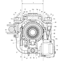
- FIG. 6 is an end view seen from the left side of FIG.
- FIG. 7 is a cross-sectional view taken along the line AA of FIG.
- FIG. 8 is a cross-sectional view taken along the line BB of FIG.
- FIG. 11 is a side view showing the steering device according to the first example of the embodiment of the present invention.
- FIG. 11A shows a state in which the column holder is moved to the rearmost side with respect to the fixing bracket
- FIG. 11B shows a state in which the upper column is moved to the rearmost side with respect to the column holder
- FIG. 11B shows the column holder. Is moved to the frontmost side with respect to the fixing bracket, and the upper column is moved to the rearmost side with respect to the column holder.
- FIG. 11C shows the column holder moved to the rearmost side with respect to the fixing bracket.
- FIG. 12 is an exploded perspective view of the steering column device according to the first example of the embodiment of the present invention.
- FIG. 13 is an exploded perspective view of the steering column device according to the first example of the embodiment of the present invention as viewed from the side opposite to FIG. 12 in the width direction.
- FIG. 14 is a side view showing the fixing bracket and the lower side telescopic actuator taken out from the steering column device according to the first example of the embodiment of the present invention.
- FIG. 15 is a perspective view showing the fixing bracket and the lower side telescopic actuator taken out from the steering column device according to the first example of the embodiment of the present invention.
- FIG. 16 is a perspective view showing a displacement bracket taken out from the steering column device according to the first example of the embodiment of the present invention.
- FIG. 17 is a diagram corresponding to FIG. 9, showing a second example of the embodiment of the present invention.
- FIG. 18 is a perspective view showing a fixed bracket, a lower side telescopic actuator, a reaction force applying device, and a linear guide taken out from the steering device according to the second example of the embodiment of the present invention.
- FIG. 19 is a perspective view showing a fixed bracket, a displacement bracket, a lower side telescopic actuator, a reaction force applying device, and a linear guide taken out from the steering device according to the second example of the embodiment of the present invention.
- the first example of the embodiment of the present invention will be described with reference to FIGS. 1 to 16.
- This example is an example in which the steering column device of the present invention is incorporated into the steering device of a steering system of a steer-by-wire system.
- the steering system 67 of the steer-by-wire system is for imparting a steering angle to the steering wheel 68 and the steering device 1 having a sensor (not shown) for measuring the steering amount of the steering wheel 68, and the pair of steering wheels 69. It is electrically connected to the steering device 70. That is, in the steering system 67 of the steer-by-wire system, the amount of operation of the steering wheel 68 by the driver is measured by the sensor of the steering device 1.
- the actuator 71 of the steering device 70 is driven, and the linear motion shafts such as the rack shaft and the screw shaft arranged in the width direction of the vehicle are displaced in the width direction of the vehicle to form a pair.
- the tie rod 72 is pushed and pulled to give a steering angle to the pair of steering wheels 69.
- the steering device 1 of this example includes a steering column device 2, a steering shaft 3, and a reaction force applying device 4.
- the front-rear direction, the vertical direction, and the width direction refer to the front-rear direction, the vertical direction, and the width direction of the vehicle with the steering device 1 attached to the vehicle.
- the steering column device 2 includes a steering column 5, a lower side telescopic actuator 6, an upper side telescopic actuator 7, and a tilt actuator 8.
- the steering column 5 includes a fixed bracket 9, a column holder 10, an upper column 11, and a linear guide 12, and is configured to have a stretchable overall length. Specifically, in the steering column 5, the fixed bracket 9 and the column holder 10 are combined in an axial relative displacement via the linear guide 12, and the column holder 10 and the upper column 11 are combined in the axial direction. The relative displacements of are combined as possible.
- the fixing bracket 9 includes a fixing plate portion 13 and a fixing side bracket portion 14.
- the fixing plate portion 13 has a rectangular shape extending in the front-rear direction when viewed from the vertical direction, and has through holes 15 penetrating in the vertical direction at two locations in the front-rear direction on both side portions in the width direction.
- the fixing bracket 9 is supported and fixed to a vehicle body (not shown) by a mounting bolt 16 inserted from below into the through hole 15 of the fixing plate portion 13. Further, as shown in FIGS. 7 to 9, the fixing plate portion 13 is bent downward from the base portion 13a arranged in the middle portion in the width direction and both ends in the width direction of the base portion 13a in the cross-sectional view seen from the front-rear direction.
- the bent portion 13b is inclined outward in the width direction toward the bottom. Further, the through hole 15 is formed in the flange portion 13c.
- the fixed side bracket portion 14 has a substantially U-shape when viewed from the front-rear direction, and is fixed to the front end portion of the fixed plate portion 13. That is, the fixed-side bracket portion 14 has a pair of fixed-side side plate portions 17a and 17b hanging downward from both end portions in the width direction of the front end portion of the fixed plate portion 13, and the fixed-side side plate portion 17a. It has a fixed-side connecting portion 18 that connects the lower ends of 17b to each other. In other words, the fixed-side connecting portion 18 is hung between the lower end portions of the pair of fixed-side side plate portions 17a and 17b.
- the column holder 10 includes a displacement bracket 19 that is supported to allow relative displacement in the axial direction (front-back direction) with respect to the fixed bracket 9, and a lower column 20 that is supported to swing vertically with respect to the displacement bracket 19. , Equipped with.
- the displacement bracket 19 includes a displacement plate portion 21, a pair of hanging plate portions 22a and 22b, and a swing support bracket portion 23.
- the displacement plate portion 21 has a rectangular shape extending in the front-rear direction when viewed from the vertical direction, and has a recess 27 on the upper surface of the front side portion. Further, as shown in FIGS. 7 to 9, the displacement plate portions 21 are connected to the thick portion 21b arranged in the middle portion in the width direction and on both sides in the width direction of the thick portion 21b in the cross-sectional view seen from the front-rear direction. It also has a thin portion 21c whose thickness is smaller than that of the thick portion 21b.
- the thick portion 21b faces the base portion 13a of the fixing plate portion 13 in the vertical direction via a gap.
- a recess 27 is formed on the upper surface of the front side portion of the thick portion 21b.
- the linear guide 12 is arranged in the recess 27.
- the thin-walled portion 21c faces the corner portion which is the connection portion between the bent portion 13b and the flange portion 13c of the fixing plate portion 13 via a slight gap.
- the pair of hanging plate portions 22a and 22b hang down from the ends on both sides in the width direction from the front side portion to the intermediate portion of the displacement plate portion 21.
- the swing support bracket portion 23 has a substantially U-shape when viewed from the front-rear direction, and is fixed to the rear end portion of the displacement plate portion 21. That is, the swing support bracket portion 23 has a pair of displacement side plate portions 24a and 24b hanging downward from both end portions in the width direction of the rear end portion of the displacement plate portion 21 and the pair of displacements. It has a displacement side connecting portion 25 that connects the lower ends of the side plate portions 24a and 24b to each other.
- the displacement side plate portion 24a on one side in the width direction (right side in FIGS. 6 to 8 and left side in FIG. 9) is a concave groove extending in the vertical direction on the inner side surface in the width direction. It has 26 (see FIG. 16).
- the displacement side connecting portion 25 has a circular hole penetrating in the vertical direction on one side portion in the width direction.
- the displacement bracket 19 is supported by the linear guide 12 so as to be relatively displaced in the axial direction with respect to the fixed bracket 9. That is, in this example, the fixed bracket 9 constitutes the first column member, and the displacement bracket 19 constitutes the second column member.
- a linear guide 12 as a low-friction sliding member having a low coefficient of friction and good sliding characteristics is arranged between the fixed bracket 9 and the displacement bracket 19.
- the linear guide 12 has a guide rail 28 having a rectangular shape extending in the axial direction (front-back direction) and a substantially U-shape when viewed from the axial direction, and the guide rail 28 is along the guide rail 28. It comprises two sliders 29, which are combined to allow axial displacement.
- the guide rail 28 is coupled and fixed to the lower surface of the base portion 13a of the fixing plate portion 13 of the fixing bracket 9 by a plurality of support bolts 30.
- each of the sliders 29 is coupled and fixed to the inside of the recess 27 of the thick portion 21b of the displacement bracket 19 by a plurality of support bolts 31.
- the displacement bracket 19 is a through hole 63 that penetrates the displacement plate portion 21 in the vertical direction at a plurality of axial directions at two locations in the width direction sandwiching the central axis of the steering column 5 in the displacement plate portion 21.
- the upper end of each of the through holes 63 is open to the bottom surface of the recess 27.
- each of the sliders 29 has screw holes 64 at two positions separated from each other in the axial direction on both side portions in the width direction of the lower surface.
- Each of the sliders 29 is supported and fixed to the inside of the recess 27 of the thick portion 21b of the displacement bracket 19 by screwing the support bolt 31 into which the through hole 63 is inserted from below into the screw hole 64.
- the displacement bracket 19 supports the relative displacement in the axial direction with respect to the fixed bracket 9.
- the linear guide 12 is arranged inside the outer peripheral surface of the lower column 20 in the width direction.
- a pair of virtual planes S extending in the vertical direction in contact with both ends in the width direction of the outer peripheral surface of the lower column 20 are shown by broken lines.
- the linear guide 12 is arranged in the region T sandwiched between the pair of virtual planes S in the width direction. Therefore, the steering column device 2 can be made more compact in the width direction as compared with the case where the low friction sliding member such as the linear guide 12 is arranged outside the outer peripheral surface of the lower column 20 in the width direction.
- the thick portion 21b of the displacement plate portion 21 is also arranged inside the outer peripheral surface of the lower column 20 in the width direction. That is, the thick portion 21b of the displacement plate portion 21 is arranged in the region T sandwiched between the pair of virtual planes S in the width direction. Therefore, the steering column device 2 can be made more compact in the width direction as compared with the case where the thick portion 21b of the displacement plate portion 21 is arranged outside the outer peripheral surface of the lower column 20 in the width direction.
- the thickness of the thick portion 21b of the displacement plate portion 21 of the displacement bracket 19 is set to be larger than the thickness of the base portion 13a of the fixed bracket 9. More specifically, the sliding direction of the linear guide 12 (front-back direction), the direction in which the linear guide 12 is restricted from being displaced by the recess 27 of the displacement plate portion 21 (width direction), and the direction perpendicular to the direction (vertical direction).
- the thickness D1 of the portion adjacent to the portion (recessed portion 27) where the linear guide 12 is arranged is the thickness d1 of the portion of the base portion 13a adjacent to the portion where the linear guide 12 is arranged. Is set larger than. As a result, the steering column device 2 can be made compact in the width direction while ensuring rigidity.
- any of a sliding linear guide, a ball circulation type linear guide, and a non-circulation roller type linear guide may be used.
- the sliding linear guide is formed by engaging the engaging protrusion formed on the slider with the rail groove formed on the guide rail.
- the ball circulation type linear guide arranges a plurality of balls so that they can roll in a load path provided between the guide rail and the slider, and inside the slider, due to the relative displacement between the guide rail and the slider.
- a circulation path is provided to return the ball that has moved to the end point of the load path to the start point of the load path.
- the non-circulating roller type linear guide is formed by rolling and contacting a plurality of rollers rotatably supported by the slider with a rolling surface formed on the guide rail.
- the illustrated linear guide 12 includes two sliders 29 (see FIG. 15). However, when the present invention is carried out, the number of sliders of the linear guide may be one or three or more.
- the lower column 20 has a substantially cylindrical shape and is supported so as to be able to swing in the vertical direction with respect to the displacement bracket 19.
- the lower column 20 has a large diameter portion 32 on the front side portion and a small diameter portion 33 having a smaller inner diameter than the large diameter portion 32 on the rear side portion.
- the lower column 20 has a slit 34 extending in the axial direction on the lower surface of the intermediate portion in the axial direction (the portion from the rear portion of the large diameter portion 32 to the front end portion of the small diameter portion 33), and is large.
- Screw holes 35a and 35b are provided on the upper surfaces of the front end of the diameter portion 32 and the front end of the small diameter portion 33, respectively.
- Screw plugs 37a and 37b, to which pads 36a and 36b made of a material having a small coefficient of friction such as polyacetal (POM) are adhesively fixed, are screwed into the screw holes 35a and 35b, respectively.
- POM polyacetal
- the lower column 20 has a rear portion thereof in the vertical direction with respect to the swing support bracket portion 23 of the displacement bracket 19 via the tilt feed screw device 38 (see FIG. 16) constituting the tilt actuator 8. Supports displacement as possible. Further, the lower column 20 pivotally supports the front side portion to the fixed side bracket portion 14 of the fixed bracket 9 supported by the vehicle body via the inner column 39 and the housing 40 of the reaction force applying device 4.
- the tilt feed screw device 38 has a screw shaft 41 having a male screw portion on the outer peripheral surface, a female screw portion screwed with the male screw portion on the inner peripheral surface, and a columnar pivot shaft on the outer peripheral surface.
- a nut 43 having a portion 42 is provided.
- the screw shaft 41 is placed in a radial rolling bearing and / Alternatively, it is rotatably supported via a bearing device 44 such as a slide bearing, and the pivot shaft portion 42 of the nut 43 is a pivot recess formed on the outer peripheral surface of the rear portion (small diameter portion 33) of the lower column 20. It is rotatably supported (bearing).
- the inner column 39 includes a cylindrical portion 45 and a flange portion 46 bent outward in the radial direction from the front end portion of the cylindrical portion 45.
- the inner column 39 is combined with the lower column 20 to allow axial relative displacement of the lower column 20.
- the pad 36a of the screw plug 37a in which the rear portion of the cylindrical portion 45 is internally fitted into the large diameter portion 32 of the lower column 20 by gap fitting and screwed into the screw hole 35a on the front side of the lower column 20 is provided. It abuts against the outer peripheral surface of the rear portion of the cylindrical portion 45.
- the inner column 39 is internally fitted to the lower column 20 so as to be relatively displaced in the axial direction of the lower column 20.
- the screw plug 37a does not directly abut on the outer peripheral surface of the cylindrical portion 45, and the pad 36a provided at the tip of the screw plug 37a abuts on the outer peripheral surface of the cylindrical portion 45, the abutting force can be easily adjusted. .. Further, the abutting force can be easily adjusted by adjusting the tightening torque of the screw plug 37a. In this way, the sliding friction force between the pad 36a and the outer peripheral surface of the cylindrical portion 45 when the inner column 39 and the lower column 20 are displaced relative to each other in the axial direction can be adjusted.
- An elastic member such as a spring may be used to adjust the abutting force of the pad 36a against the cylindrical portion 45.
- one screw hole 35a is formed on the front side of the lower column 20, and a screw plug 37a having a pad 36a is screwed into the one screw hole 35a.
- a plurality of screw holes 35a are provided.
- a screw plug 37a having a pad 36a may be screwed into each of the plurality of screw holes 35a.
- the housing 40 of the reaction force applying device 4 is supported and fixed to the inner column 39 by a fixing bolt 48 inserted from the rear side into the through hole 47 formed in the flange portion 46 of the inner column 39. Further, the housing 40 is pivotally supported with respect to the fixing bracket 9 by a pivot bolt 49 through which a through hole formed in the fixing side plate portions 17a and 17b of the fixing side bracket portion 14 is inserted.
- the upper column 11 has a substantially cylindrical shape, and is combined so as to be relatively displaced in the axial direction with respect to the column holder 10.
- the upper column 11 has a pad 36b of a screw plug 37b in which the front side portion is internally fitted into the small diameter portion 33 of the lower column 20 by gap fitting and screwed into the screw hole 35b on the rear side of the lower column 20. It abuts against the outer peripheral surface of the front side portion of the upper column 11.
- the upper column 11 is internally fitted to the lower column 20 so as to be relatively displaced in the axial direction of the lower column 20.
- the screw plug 37b does not directly abut on the outer peripheral surface of the upper column 11, and the pad 36b provided at the tip of the screw plug 37b abuts on the outer peripheral surface of the upper column 11, so that the abutting force can be adjusted. Is easy. Further, the abutting force can be easily adjusted by adjusting the tightening torque of the screw plug 37b. In this way, the sliding friction force between the pad 36b and the outer peripheral surface of the upper column 11 when the upper column 11 and the lower column 20 are displaced relative to each other in the axial direction can be adjusted.
- An elastic member such as a spring may be used to adjust the abutting force of the pad 36b against the outer peripheral surface of the upper column 11.
- one screw hole 35b is formed on the rear side of the lower column 20, and a screw plug 37b having a pad 36b is screwed into the one screw hole 35b.
- a plurality of screw holes 35b are provided.
- a screw plug 37b having a pad 36b may be screwed into each of the plurality of screw holes 35b.
- the lower side telesco actuator 6 has a lower side telesco motor 50, and the column holder 10 is displaced in the axial direction with respect to the fixed bracket 9 using the lower side telesco motor 50 as a drive source.
- the lower side telesco actuator 6 constitutes a telesco actuator
- the lower side telesco motor 50 constitutes a telesco motor.
- the lower side telesco actuator 6 further includes a lower side feed screw device 51 for converting the rotational motion of the output shaft of the lower side telesco motor 50 into a linear motion.
- the lower side feed screw device 51 has a male screw portion on the outer peripheral surface, a screw shaft 52 rotationally driven by the lower side telescopic motor 50, and a nut having a female screw portion screwed with the male screw portion on the inner peripheral surface. 53 and.
- the screw shaft 52 is rotatably supported by the fixing bracket 9, and the nut 53 is supported and fixed to the displacement bracket 19 of the column holder 10.
- the screw shaft 52 is placed outside the width direction of the fixed side plate portion 17b on the other side in the width direction (left side in FIGS. 6 to 8 and right side in FIG. 9) of the fixed side bracket portion 14 constituting the fixed bracket 9. It is rotatably fixed to the side surface (other side surface in the width direction), and the nut 53 is supported and fixed to the outer surface in the width direction of the hanging plate portion 22b on the other side in the width direction of the displacement bracket 19. Further, the lower side telescopic motor 50 is supported and fixed to the fixed side bracket portion 14.
- the displacement bracket 19 Is displaced with respect to the fixed bracket 9 in the axial direction of the fixed bracket 9, that is, in the front-rear direction.
- the upper side telesco actuator 7 has an upper side telesco motor 54, and the upper column 11 is displaced in the axial direction with respect to the column holder 10 by using the upper side telesco motor 54 as a drive source.
- the upper telesco actuator 7 further includes an upper feed screw device 55 for converting the rotational motion of the output shaft of the upper telesco motor 54 into a linear motion.
- the upper side feed screw device 55 has a male screw portion on the outer peripheral surface, a screw shaft 56 rotationally driven by the upper telesco motor 54, and a nut having a female screw portion screwed with the male screw portion on the inner peripheral surface. 57 and.
- the screw shaft 56 is supported only rotatably with respect to the lower column 20 of the column holder 10, and the nut 57 is supported and fixed to the upper column 11. More specifically, the screw shaft 56 is rotatably supported only on the lower surface of the front side portion of the large diameter portion 32 of the lower column 20, and the nut 57 is supported and fixed to the lower surface of the front side portion of the upper column 11. is doing. Further, the upper telesco motor 54 is supported and fixed to the lower column 20.
- the tilt actuator 8 has a tilt motor 58 and a tilt feed screw device 38.
- the tilt actuator 8 rotationally drives the screw shaft 41 of the tilt feed screw device 38 by the tilt motor 58 via a reduction mechanism such as a worm reducer, and moves the nut 43 in the vertical direction along the screw shaft 41.
- a reduction mechanism such as a worm reducer
- the steering shaft 3 is a combination of the inner shaft 59 and the outer shaft 60, which enables relative displacement in the axial direction and makes relative rotation impossible.
- the steering shaft 3 is formed by spline-engaging the rear portion of the front inner shaft 59 and the front portion of the rear outer shaft 60.
- the steering shaft 3 is rotatably supported inside the steering column 5 of the steering column device 2 in the radial direction. Specifically, the front end of the outer shaft 60 is rotatably supported by the radial rolling bearing 61a on the front end of the upper column 11, and the rear end of the outer shaft 60 is supported by the upper column 11. A radial rolling bearing 61b rotatably supports the rear end portion. Therefore, the steering shaft 3 expands and contracts together with the steering column 5.
- the steering wheel 68 is supported at the rear end of the steering shaft 3, that is, the rear end of the outer shaft 60. Further, a reaction force applying device 4 for applying an operating reaction force to the steering wheel 68 is connected to the front end of the steering shaft 3, that is, the front end of the inner shaft 59.
- the reaction force applying device 4 includes a housing 40, a reaction force applying motor (not shown), and a speed reducer.
- the reaction force applying device 4 drives the reaction force applying motor when the steering wheel 68 is operated by the driver, and the torque of the reaction force applying motor is increased by the speed reducer housed inside the housing 40. Therefore, it is applied to the steering shaft 3.
- an operating reaction force is applied to the steering wheel 68.
- the magnitude of the reaction force applied to the steering wheel 68 is determined according to the steering angle of the steering wheel 68 acquired by the sensor, the torque applied to the steering shaft 3, and the like.
- the reducer is composed of, for example, a worm reducer.
- the column holder 10 (displacement bracket 19) is axially oriented with respect to the fixed bracket 9 based on the energization of the lower side telesco motor 50.
- the upper column 11 is displaced relative to the column holder 10 (lower column 20) in the axial direction (front-back direction) based on the relative displacement in the (front-back direction) and / or the energization of the upper-side telesco motor 54.
- the displacement bracket 19 is generated by energizing the lower-side telesco motor 50 and rotationally driving the screw shaft 52 of the lower-side feed screw device 51 by the lower-side telesco motor 50 to displace the nut 53 in the front-rear direction.
- the upper side telesco motor 54 is energized, and the upper side telesco motor 54 rotationally drives the screw shaft 56 of the upper side feed screw device 55 to displace the nut 57 in the front-rear direction.
- the column 11 is displaced with respect to the lower column 20 in the axial direction of the lower column 20, that is, in the front-rear direction.
- the total length of the steering column 5 is expanded and contracted, and the total length of the steering shaft 3 is expanded and contracted to adjust the front-rear position of the steering wheel 68.
- the energization of the lower side telesco motor 50 and / or the upper side telesco motor 54 is stopped.
- the rear portion of the lower column 20 is displaced in the vertical direction with respect to the displacement bracket 19 based on the energization of the tilt motor 58. That is, by energizing the tilt motor 58 and rotationally driving the screw shaft 41 of the tilt feed screw device 38 by the tilt motor 58 to displace the nut 43 in the vertical direction, the lower column 20 is pivotally bolted. The rear portion of the lower column 20 is displaced in the vertical direction while swinging around the 49. As a result, the rear end of the steering shaft 3 rotatably supported inward in the radial direction of the steering column 5 is displaced in the vertical direction, and the vertical position of the steering wheel 68 is adjusted. After adjusting the vertical position of the steering wheel 68 to a desired position, the energization of the tilt motor 58 is stopped.
- the adjustment of the front-rear position of the steering wheel 68 and the adjustment of the up-down position can be performed at the same time, or can be performed independently (back and forth in time).
- the steering column 5 is combined with the fixed bracket 9 and the column holder 10 so as to enable relative displacement in the axial direction, and the column holder 10 and the upper column 11 are combined so as to enable relative displacement in the axial direction. It is configured. That is, the steering column 5 has a two-stage telescopic structure. Therefore, while ensuring a sufficient amount of expansion and contraction of the entire length of the steering column 5, the axial dimensions of the screw shaft 52 of the lower side feed screw device 51 and the screw shaft 56 of the upper side feed screw device 55 become excessive. Can be prevented.
- the column holder 10 is displaced in the axial direction with respect to the fixed bracket 9 by the lower side telescopic actuator 6, and the upper column 11 is attached to the column holder 10 by the upper side telescopic actuator 7. It is configured to be displaced in the axial direction. Therefore, even if one of the lower side telesco actuator 6 and the upper side telesco actuator 7 has a failure such as a failure, the other actuator adjusts the front-rear position of the steering wheel 68. be able to.
- the column holder 10 is energized by simultaneously energizing the lower side telescopic motor 50 of the lower side telescopic actuator 6 and the upper side telescopic motor 54 of the upper side telescopic actuator 7.
- the fixing bracket 9 is displaced in the axial direction
- the upper column 11 can be displaced in the axial direction with respect to the column holder 10. Therefore, it is easy to increase the expansion / contraction speed of the steering column 5 as compared with the structure in which the entire length of the steering column is expanded / contracted by one electric motor.
- the fixed bracket 9 and the column holder 10 are combined via a linear guide 12 having high component accuracy and assembly accuracy. Therefore, it is possible to secure the support rigidity of the column holder 10 with respect to the fixed bracket 9 and reduce the resistance (displacement resistance) of the column holder 10 to be displaced in the axial direction with respect to the fixed bracket 9 at a high level. Further, by reducing the displacement resistance of the column holder 10, the lower side telescopic actuator 6 for vertically displaces the column holder 10 with respect to the fixed bracket 9 can be miniaturized, and the column holder 10 can be miniaturized. It is possible to suppress the operating noise when the is displaced relative to the fixed bracket 9 in the axial direction.
- the expansion / contraction speed of the steering column 5 can be increased.
- the amount of adjustment of the front-rear position of the steering wheel 68 is large, such as when the steering wheel 68 is stored inside the dashboard or when the steering wheel 68 stored inside the dashboard is deployed. , The effect of increasing the expansion / contraction speed of the steering column 5 can be remarkably obtained.
- the steering wheel 68 is steered from the steering wheel 68 when the driver gets on and off the vehicle. It is possible to sufficiently secure the rigidity against the downward force applied to the column 5 and the lateral force applied to the steering column 5 from the steering wheel 68 when traveling on a curve.
- the steering device 1 of this example when adjusting the front-rear position of the steering wheel 68, for example, after the fixed bracket 9 is largely displaced with respect to the column holder 10 at high speed in the axial direction, the column with respect to the fixed bracket 9 is used.
- the front-rear position of the steering wheel 68 can be adjusted to a desired position.
- the guide rail 28 of the linear guide 12 is coupled and fixed to the lower surface of the fixing plate portion 13 of the fixing bracket 9 by a plurality of support bolts 30, and the slider 29 is connected and fixed to the displacement plate of the displacement bracket 19. It is coupled and fixed to the upper surface of the portion 21 by a plurality of support bolts 31. Since the linear guide 12 has high component accuracy and assembly accuracy, the column holder 10 is displaced in the axial direction with respect to the fixed bracket 9 after the fixing bracket 9 and the column holder 10 are combined via the linear guide 12. There is no need to adjust the resistance (displacement resistance). In short, according to the steering column device 2 of this example, even when the steering column 5 has a two-stage telescopic structure, it can be easily configured and the assembly cost can be kept low.
- the linear guide 12 is arranged in the upper portion of the portion between the fixed bracket 9 and the displacement bracket 19, but in the case of carrying out the present invention, the linear guide is provided between the fixed bracket and the displacement bracket. It can also be placed in the lower part of the intervening part.
- the linear guides can be arranged on both sides in the width direction of the portion between the fixed bracket and the displacement bracket. In this case, one linear guide is arranged on both sides in the width direction of the portion between the fixed bracket and the displacement bracket.
- the fixed bracket 9 and the column holder 10 are combined via the linear guide 12, but instead of or in addition to this, the column holder (lower column) and the upper column are combined. Can also be combined via a linear guide.
- the present invention can also be applied to a steering column device having only a telesco mechanism. Further, in this example, the case where the steering column device of the present invention is applied to the steering device of the steering system of the steer-by-wire system has been described, but the steering column device of the present invention is not limited to this, and the steering column device of the present invention is not limited to this. It can also be applied to a mechanical steering system in which the end is mechanically connected to the input shaft (pinion shaft) of the steering gear unit via a universal joint or an intermediate shaft. The mechanical steering system can be provided with an assist device for reducing the force required for the driver to operate the steering wheel. That is, the steering column device of the present invention can be applied to a power steering system such as an electric power steering system.
- a power steering system such as an electric power steering system.
- the steering column 5 of this example has a two-stage telescopic structure
- the present invention can also be applied to a steering column device in which the steering column has a one-stage telescopic structure.
- FIGS. 17 to 19 A second example of the embodiment of the present invention will be described with reference to FIGS. 17 to 19.
- the support structure of the slider 29a constituting the linear guide 12a with respect to the displacement bracket 19a is different from that of the steering column device 2 of the first embodiment.
- the position of the support bolt 31a for supporting the slider 29a with respect to the displacement bracket 19a is positioned outside in the width direction from the first example of the embodiment.
- the displacement bracket 19a has through holes 63a that penetrate the displacement plate portion 21 in the vertical direction at a plurality of axial directions at two locations in the width direction sandwiching the central axis of the steering column 5a in the displacement plate portion 21. ..
- each of the through holes 63a is formed at a plurality of positions in the axial direction of the displacement plate portion 21 at two positions in the width direction sandwiching the portion where the recess 27 is formed.
- the slider 29a of the linear guide 12a has a substantially rectangular columnar shape, and has a main body portion 65 having an engaging portion on the upper surface thereof that is engaged with the guide rail 28 so as to be axially displaced along the guide rail 28.
- a pair of flange portions 66 projecting outward in the width direction from the upper ends of both side surfaces in the width direction of the main body portion 65 are provided.
- the slider 29a has screw holes 64a at a plurality of axial directions on the lower surface of each of the flange portions 66.
- the slider 29a has a support bolt 31a formed in the flange portion 66 through which the through hole 63a is inserted from below in a state where the lower portion of the main body portion 65 is engaged (arranged) inside the recess 27 of the displacement bracket 19a. By screwing into the screw hole 64a, it is supported and fixed to the upper surface of the displacement bracket 19a.
- the position of the support bolt 31a for supporting the slider 29a with respect to the displacement bracket 19a is positioned outside in the width direction from the first example of the embodiment. Therefore, it is easy to secure the support rigidity of the slider 29a with respect to the displacement bracket 19a. Further, it is possible to sufficiently secure a vertical distance (clearance) between the head of the support bolt 31a and the upper surface of the lower column 20. As a result, a sufficient amount of swingable amount of the lower column 20 in the vertical direction (adjustable amount of the vertical position of the steering wheel) with respect to the displacement bracket 19a can be sufficiently secured.
- the composition and action / effect of other parts are the same as those of the first example of the embodiment.
- FIG. 20 is a cross-sectional view showing the steering device of the present embodiment, and is a view corresponding to FIG. 7.
- a rolling member 80 as a low friction sliding member is arranged in a portion between the fixed bracket 9 and the displacement bracket 19.
- the rolling member 80 is exemplified by a spherical or columnar rolling element made of steel. In the illustrated example, a spherical rolling element is applied.
- Grooves 82 and 81 on which the rolling member 80 can be arranged are formed on the facing surfaces of the pair of bent portions 13b and the pair of thick-walled portions 21b, respectively. Then, the rolling member 80 is arranged between the groove portions 82 and 81.
- the number of rolling members 80 is not particularly limited, and a plurality of rolling members 80 may be arranged in the front-rear direction.
- the displacement bracket 19 is supported by the rolling member 80 so as to be relatively displaced in the axial direction with respect to the fixed bracket 9.
- This embodiment is the same as the linear guides 12 and 12a of the first and second examples of the embodiment in that the rolling mechanism is used as the low friction sliding member.
- the pair of rolling members 80 are arranged and fixed at two locations (a pair of bent portions 13b) in the width direction of the fixing bracket 9 so as to face each other in the width direction with the thick portion 21b interposed therebetween. Since the bracket 9 and the displacement bracket 19 have a structure having a tightening allowance in the width direction and the vertical direction, movements other than relative movement in the axial direction can be restricted.
- the number of parts is reduced and the structure can be simplified as compared with the case where the linear guides 12 and 12a are used as in the first and second examples of the embodiment, so that the linear guide can be simplified. It is possible to reduce the cost while having the same characteristics as those of 12 and 12a.
- the pair of rolling members 80 are arranged inside the outer peripheral surface of the lower column 20 in the width direction.
- a pair of virtual planes S extending in the vertical direction in contact with both ends in the width direction of the outer peripheral surface of the lower column 20 are shown by broken lines.
- a pair of rolling members 80 are arranged in the region T sandwiched between the pair of virtual planes S in the width direction. Therefore, the steering column device can be made more compact in the width direction as compared with the case where the pair of rolling members 80 are arranged outside the outer peripheral surface of the lower column 20 in the width direction.
- the thickness of the thick portion 21b of the displacement plate portion 21 of the displacement bracket 19 is set to be larger than the thickness of the bent portion 13b of the fixed bracket 9.
- the thickness D2 of the portion of the thick portion 21b adjacent to the portion where the rolling member 80 is arranged is the portion of the bent portion 13b adjacent to the portion (groove portion 81) where the rolling member 80 is arranged.
- the thickness is set to be larger than d2.
- the fixing bracket 9 and the column holder 10 are combined via the rolling member 80, but instead of or in addition to this, the column holder (lower column) and the upper column are used. Can also be combined via the rolling member 80.
- FIG. 21 is a cross-sectional view showing the steering device of the present embodiment, and is a diagram corresponding to FIG. 7.
- a sliding member 90 as a low friction sliding member is arranged in a portion between the fixed bracket 9 and the displacement bracket 19.
- the sliding member 90 of this example has a rectangular cross section and a rectangular parallelepiped shape extending in the front-rear direction, but the shape is not limited.
- the sliding member 90 is fixed to one of the fixed bracket 9 and the displacement bracket 19, and slides while being guided to the other to enable relative movement of the fixed bracket 9 and the displacement bracket 19 in the axial direction.
- the sliding member 90 is fixed to either one of the groove portions 92 and 91 by fitting, welding, adhesion, or the like, and can slide while being guided to the other.
- a self-lubricating resin such as PTFE (polytetrafluoroethylene resin) for the sliding member 90, friction during operation can be reduced.
- a material other than the self-lubricating resin may be appropriately selected and adopted.
- the displacement bracket 19 is guided and supported by the sliding member 90 so as to be relatively displaced in the axial direction with respect to the fixed bracket 9.
- the pair of sliding members 90 are arranged at two locations (a pair of bent portions 13b) in the width direction of the fixing bracket 9 so as to face each other in the width direction with the thick portion 21b interposed therebetween. Since the 9 and the displacement bracket 19 have a structure having a tightening allowance in the width direction and the vertical direction, movements other than the relative movement in the axial direction can be regulated. Further, according to the present embodiment, the number of parts is reduced and the structure can be simplified as compared with the case where the linear guides 12 and 12a are used as in the first and second examples of the embodiment, so that the linear guide can be simplified. It is possible to reduce the cost while having the same characteristics as those of 12 and 12a.
- the pair of sliding members 90 are arranged inside the outer peripheral surface of the lower column 20 in the width direction.
- a pair of virtual planes S extending in the vertical direction in contact with both ends in the width direction of the outer peripheral surface of the lower column 20 are shown by broken lines.
- a pair of sliding members 90 are arranged in the region T sandwiched between the pair of virtual planes S in the width direction. Therefore, the steering column device 2 can be made more compact in the width direction than when the pair of sliding members 90 are arranged outside the outer peripheral surface of the lower column 20 in the width direction.
- the thickness of the thick portion 21b of the displacement plate portion 21 of the displacement bracket 19 is set to be larger than the thickness of the bent portion 13b of the fixed bracket 9.
- the thickness D3 of the portion of the thick portion 21b adjacent to the portion where the sliding member 90 is arranged is the portion of the bent portion 13b adjacent to the portion where the sliding member 90 is arranged (groove portion 91).
- the thickness is set to be larger than d3.
- the fixing bracket 9 and the column holder 10 are combined via the sliding member 90, but instead of or in addition to this, the column holder (lower column) and the upper column are used. Can also be combined via the sliding member 90.
Abstract
This steering column device is provided with a steering column and an actuator for telescopic adjustment. The steering column has: a first column member; a second column member that is combined with the first column member so as to be displaceable relative thereto in an axial direction; and a low-friction sliding member disposed at an interval between the first column member and the second column member. The actuator for telescopic adjustment has a motor for telescopic adjustment and displaces the second column member relative to the first column member in the axial direction by using the motor for telescopic adjustment as a driving source.
Description
本発明は、電動モータを駆動源として、ステアリングコラムの全長を伸縮させる、ステアリングコラム装置に関する。
The present invention relates to a steering column device that expands and contracts the entire length of the steering column using an electric motor as a drive source.
近年、自動車の自動運転技術が急速に進展している。このため、近い将来、自動運転のレベルは、特定の条件下においては自動車が自動で運転を行うレベル(レベル3、4)や、完全自動運転のレベル(レベル5)にまで到達すると考えられている。このような自動運転技術を備える自動車においては、運転者がステアリングホイールを操作する必要がなくなる。
In recent years, autonomous driving technology for automobiles has been rapidly advancing. Therefore, in the near future, the level of autonomous driving is expected to reach the level at which automobiles automatically drive under specific conditions (levels 3 and 4) and the level of fully automated driving (level 5). There is. In an automobile equipped with such an automatic driving technique, the driver does not need to operate the steering wheel.
自動運転中は、ステアリングホイールを前方に大きく変位させてダッシュボードの内側に格納し、運転席前方の空間を広く確保することが好ましい。ステアリングホイールをダッシュボードの内側に格納するためには、ステアリングコラムの伸縮可能量を十分に確保する必要がある。
During automatic driving, it is preferable to displace the steering wheel forward and store it inside the dashboard to secure a large space in front of the driver's seat. In order to store the steering wheel inside the dashboard, it is necessary to secure a sufficient amount of expansion and contraction of the steering column.
米国特許出願公開第2019/210632号明細書(特許文献1)には、3つのジャケットをテレスコープ状に組み合わせることにより、全長の伸縮可能量を十分に確保することができるステアリングコラムが開示されている。具体的には、ステアリングコラムは、アッパジャケットとミドルジャケットとを、複数個のボールを介して伸縮可能に嵌合させ、かつ、ミドルジャケットとロアジャケットとを、複数個のボールを介して伸縮可能に嵌合させることにより構成されている。このようなステアリングコラムを伸縮させる際には、アッパ側のモータを駆動し、ねじ軸を回転させて、該ねじ軸に螺合されたナットを軸方向に移動させることにより、ミドルジャケットに対しアッパジャケットを軸方向に相対変位させ、及び/又は、ロア側のモータを駆動し、ねじ軸を回転させて、該ねじ軸に螺合されたナットを軸方向に移動させることにより、ロアジャケットに対しミドルジャケットを軸方向に相対変位させる。
U.S. Patent Application Publication No. 2019/210632 (Patent Document 1) discloses a steering column that can sufficiently secure a stretchable amount of the total length by combining three jackets in a telescope shape. There is. Specifically, the steering column allows the upper jacket and the middle jacket to be stretchably fitted via a plurality of balls, and the middle jacket and the lower jacket to be stretchable via a plurality of balls. It is configured by fitting in. When expanding and contracting such a steering column, the motor on the upper side is driven, the screw shaft is rotated, and the nut screwed to the screw shaft is moved in the axial direction to move the upper with respect to the middle jacket. By relatively displaced the jacket in the axial direction and / or by driving the motor on the lower side to rotate the screw shaft and moving the nut screwed to the screw shaft in the axial direction with respect to the lower jacket. The middle jacket is displaced relative to the axis.
米国特許出願公開第2019/210632号明細書に記載のステアリングコラムにおいて、それぞれのジャケット同士の間のがたつきを抑えるためには、それぞれのジャケット同士の間に挟持された複数個のボールに、予圧を付与する必要がある。ただし、これらのボールに予圧を付与すると、それぞれのジャケット同士が軸方向に相対変位する際のボールの転がり抵抗が大きくなり、ステアリングコラムの伸縮速度が低下するといった問題を生じる。なお、ねじ軸を回転させるためのモータとして、出力トルクが大きいモータを使用すれば、ステアリングコラムの伸縮速度を十分に確保することができるが、モータが大型化するといった問題を生じる。
In the steering column described in U.S. Patent Application Publication No. 2019/210632, in order to suppress rattling between the jackets, a plurality of balls sandwiched between the jackets are used. Preload needs to be applied. However, when a preload is applied to these balls, there arises a problem that the rolling resistance of the balls when the jackets are displaced relative to each other in the axial direction increases, and the expansion / contraction speed of the steering column decreases. If a motor having a large output torque is used as the motor for rotating the screw shaft, the expansion / contraction speed of the steering column can be sufficiently secured, but there is a problem that the motor becomes large.
本発明は、上述のような事情に鑑みて、伸縮速度を十分に確保することができる、ステアリングコラム装置を実現することを目的としている。
In view of the above circumstances, the present invention aims to realize a steering column device that can sufficiently secure the expansion / contraction speed.
本発明の上記目的は、下記の構成により達成される。
(1) ステアリングコラムと、テレスコ用アクチュエータと、を備えるステアリングコラム装置であって、
前記ステアリングコラムは、
第1のコラム部材と、
前記第1のコラム部材に対し軸方向の相対変位を可能に組み合わされた第2のコラム部材と、
前記第1のコラム部材と前記第2のコラム部材との間部分に配置された低摩擦摺動部材と、
を有し、
前記テレスコ用アクチュエータは、テレスコ用モータを有し、前記テレスコ用モータを駆動源として、前記第1のコラム部材に対し前記第2のコラム部材を軸方向に変位させる
ステアリングコラム装置。
(2) 前記ステアリングコラムは、固定ブラケットと、前記固定ブラケットに対し軸方向の相対変位を可能に組み合わされたコラムホルダと、前記コラムホルダに対し軸方向の相対変位を可能に組み合わされたアッパコラムと、を有し、かつ、前記低摩擦摺動部材が、前記固定ブラケットと前記コラムホルダとの間部分と、前記コラムホルダと前記アッパコラムとの間部分とのうちの少なくとも一方の間部分に配置されており、
ロア側テレスコ用モータを有し、前記ロア側テレスコ用モータを駆動源として、前記固定ブラケットに対し前記コラムホルダを軸方向に変位させるロア側テレスコ用アクチュエータと、
アッパ側テレスコ用モータを有し、前記アッパ側テレスコ用モータを駆動源として、前記コラムホルダに対し前記アッパコラムを軸方向に変位させるアッパ側テレスコ用アクチュエータと、を備える、
(1)に記載のステアリングコラム装置。
(3) 前記コラムホルダは、前記固定ブラケットに対し軸方向の相対変位を可能に支持された変位ブラケットと、前記変位ブラケットに対し上下方向の揺動を可能に支持されたロアコラムと、を含み、
チルト用モータを有し、前記チルト用モータを駆動源として、前記変位ブラケットに対し前記ロアコラムを上下方向に変位させるチルト用アクチュエータをさらに備える、
(2)に記載のステアリングコラム装置。
(4) 前記ステアリングコラムは、固定ブラケットと、前記固定ブラケットに対し軸方向の相対変位を可能に組み合わされたコラムホルダと、前記コラムホルダに対し軸方向の相対変位を可能に組み合わされたアッパコラムと、を有し、
前記コラムホルダは、前記固定ブラケットに対し軸方向の相対変位を可能に支持された変位ブラケットと、前記変位ブラケットに対し上下方向の揺動を可能に支持されたロアコラムと、を含み、
前記低摩擦摺動部材は、前記ロアコラムの外周面よりも幅方向内側に配置される
(1)に記載のステアリングコラム装置。
(5) 前記低摩擦摺動部材は、前記固定ブラケットと前記変位ブラケットとの間部分に配置されており、
前記変位ブラケットは、厚肉部を有し、
前記厚肉部に前記低摩擦摺動部材が配置される
(4)に記載のステアリングコラム装置。
(6) 前記厚肉部は、前記ロアコラムの外周面よりも幅方向内側に配置される
(5)に記載のステアリングコラム装置。
(7) 前記厚肉部のうち前記低摩擦摺動部材が配置される箇所に隣接する部分の厚さは、前記固定ブラケットのうち前記低摩擦摺動部材が配置される箇所に隣接する部分の厚さよりも大きい
(5)又は(6)に記載のステアリングコラム装置。
(8) 前記低摩擦摺動部材は、リニアガイドであり、
前記リニアガイドは、
軸方向に伸長するガイドレールと、
前記ガイドレールに対し該ガイドレールに沿って軸方向の変位を可能に組み合わされたスライダと、
を含む、
(1)~(7)の何れか1つに記載のステアリングコラム装置。
(9) 前記リニアガイドは、前記固定ブラケットと前記変位ブラケットとの間部分に配置されている、
(8)に記載のステアリングコラム装置。
(10) 前記変位ブラケットは、上側部分に、上下方向に貫通する通孔を有しており、
前記スライダは、下面に開口するねじ孔を有し、前記通孔を下方から挿通した支持ボルトを前記ねじ孔に螺合することにより、前記変位ブラケットの上面に支持固定されており、
前記ガイドレールは、前記固定ブラケットの下面に支持固定されている、
(9)に記載のステアリングコラム装置。
(11) 前記通孔が、前記ステアリングコラムの中心軸を挟んだ幅方向両側部分に配置されており、かつ、前記ねじ孔が、前記ステアリングコラムの中心軸を挟んだ幅方向両側部分に配置されている、
(10)に記載のステアリングコラム装置。
(12) 前記低摩擦摺動部材は、転がり部材である
(1)~(7)の何れか1つに記載のステアリングコラム装置。
(13) 前記転がり部材は、互いに幅方向に対向するように、幅方向二箇所に配置される
(12)に記載のステアリングコラム装置。
(14) 前記低摩擦摺動部材は、滑り部材である
(1)~(7)の何れか1つに記載のステアリングコラム装置。
(15) 前記滑り部材は、互いに幅方向に対向するように、幅方向二箇所に配置される
(14)に記載のステアリングコラム装置。 The above object of the present invention is achieved by the following configuration.
(1) A steering column device including a steering column and a telescopic actuator.
The steering column is
The first column member and
A second column member that is combined to enable axial relative displacement with respect to the first column member.
A low friction sliding member arranged in a portion between the first column member and the second column member,
Have,
The telesco actuator has a telesco motor, and is a steering column device that uses the telesco motor as a drive source to axially displace the second column member with respect to the first column member.
(2) The steering column is an upper column in which a fixed bracket, a column holder capable of axial relative displacement with respect to the fixed bracket, and an upper column capable of axial relative displacement with respect to the column holder are combined. And, the low friction sliding member is placed in at least one of the portion between the fixing bracket and the column holder and the portion between the column holder and the upper column. Have been placed and
A lower-side telesco actuator that has a lower-side telesco motor and that uses the lower-side telesco motor as a drive source to displaced the column holder in the axial direction with respect to the fixed bracket.
It has an upper-side telesco motor, and is provided with an upper-side telesco actuator that displaces the upper column in the axial direction with respect to the column holder using the upper-side telesco motor as a drive source.
The steering column device according to (1).
(3) The column holder includes a displacement bracket that is supported so as to be laterally displaced in the axial direction with respect to the fixed bracket, and a lower column that is supported so as to be able to swing in the vertical direction with respect to the displacement bracket.
It has a tilt motor, and further includes a tilt actuator that displaces the lower column in the vertical direction with respect to the displacement bracket using the tilt motor as a drive source.
The steering column device according to (2).
(4) The steering column is an upper column in which a fixed bracket, a column holder capable of axial relative displacement with respect to the fixed bracket, and an upper column capable of axial relative displacement with respect to the column holder are combined. And have
The column holder includes a displacement bracket that is supported for axial relative displacement with respect to the fixed bracket and a lower column that is supported for vertical swing with respect to the displacement bracket.
The steering column device according to (1), wherein the low friction sliding member is arranged inside in the width direction with respect to the outer peripheral surface of the lower column.
(5) The low friction sliding member is arranged in a portion between the fixed bracket and the displacement bracket.
The displacement bracket has a thick portion and has a thick portion.
The steering column device according to (4), wherein the low friction sliding member is arranged in the thick portion.
(6) The steering column device according to (5), wherein the thick portion is arranged inside in the width direction with respect to the outer peripheral surface of the lower column.
(7) The thickness of the portion of the thick portion adjacent to the portion where the low friction sliding member is arranged is the thickness of the portion of the fixing bracket adjacent to the portion where the low friction sliding member is arranged. The steering column device according to (5) or (6), which is larger than the thickness.
(8) The low friction sliding member is a linear guide.
The linear guide is
A guide rail that extends in the axial direction and
A slider combined with the guide rail to allow axial displacement along the guide rail,
including,
The steering column device according to any one of (1) to (7).
(9) The linear guide is arranged in a portion between the fixed bracket and the displacement bracket.
The steering column device according to (8).
(10) The displacement bracket has a through hole penetrating in the vertical direction in the upper portion.
The slider has a screw hole that opens on the lower surface, and is supported and fixed to the upper surface of the displacement bracket by screwing a support bolt into which the through hole is inserted from below into the screw hole.
The guide rail is supported and fixed to the lower surface of the fixing bracket.
The steering column device according to (9).
(11) The through holes are arranged on both side portions in the width direction sandwiching the central axis of the steering column, and the screw holes are arranged on both side portions in the width direction sandwiching the central axis of the steering column. ing,
The steering column device according to (10).
(12) The steering column device according to any one of (1) to (7), wherein the low friction sliding member is a rolling member.
(13) The steering column device according to (12), wherein the rolling members are arranged at two locations in the width direction so as to face each other in the width direction.
(14) The steering column device according to any one of (1) to (7), wherein the low friction sliding member is a sliding member.
(15) The steering column device according to (14), wherein the sliding members are arranged at two locations in the width direction so as to face each other in the width direction.
本発明のステアリングコラム装置によれば、伸縮速度を十分に確保することができる。
According to the steering column device of the present invention, a sufficient expansion / contraction speed can be secured.
本発明の実施の形態の第1例について、図1~図16により説明する。本例は、本発明のステアリングコラム装置を、ステアバイワイヤ方式のステアリングシステムの操舵装置に組み込んだ例である。ステアバイワイヤ方式のステアリングシステム67は、ステアリングホイール68及び該ステアリングホイール68の操舵量を測定するためのセンサ(図示省略)を有する操舵装置1と、一対の操舵輪69に舵角を付与するための転舵装置70と、を電気的に接続してなる。すなわち、ステアバイワイヤ方式のステアリングシステム67では、運転者によるステアリングホイール68の操作量を、操舵装置1のセンサにより測定する。そして、センサの出力信号に基づいて、転舵装置70のアクチュエータ71を駆動し、車両の幅方向に配置されたラック軸やねじ軸などの直動軸を車両の幅方向に変位させ、一対のタイロッド72を押し引きして、一対の操舵輪69に舵角を付与する。
The first example of the embodiment of the present invention will be described with reference to FIGS. 1 to 16. This example is an example in which the steering column device of the present invention is incorporated into the steering device of a steering system of a steer-by-wire system. The steering system 67 of the steer-by-wire system is for imparting a steering angle to the steering wheel 68 and the steering device 1 having a sensor (not shown) for measuring the steering amount of the steering wheel 68, and the pair of steering wheels 69. It is electrically connected to the steering device 70. That is, in the steering system 67 of the steer-by-wire system, the amount of operation of the steering wheel 68 by the driver is measured by the sensor of the steering device 1. Then, based on the output signal of the sensor, the actuator 71 of the steering device 70 is driven, and the linear motion shafts such as the rack shaft and the screw shaft arranged in the width direction of the vehicle are displaced in the width direction of the vehicle to form a pair. The tie rod 72 is pushed and pulled to give a steering angle to the pair of steering wheels 69.
本例の操舵装置1は、ステアリングコラム装置2と、ステアリングシャフト3と、反力付与装置4と、を備える。なお、操舵装置1に関して前後方向、上下方向及び幅方向とは、操舵装置1を車両に取り付けた状態での車両の前後方向、上下方向及び幅方向をいう。
The steering device 1 of this example includes a steering column device 2, a steering shaft 3, and a reaction force applying device 4. Regarding the steering device 1, the front-rear direction, the vertical direction, and the width direction refer to the front-rear direction, the vertical direction, and the width direction of the vehicle with the steering device 1 attached to the vehicle.
ステアリングコラム装置2は、ステアリングコラム5と、ロア側テレスコ用アクチュエータ6と、アッパ側テレスコ用アクチュエータ7と、チルト用アクチュエータ8と、を備える。
The steering column device 2 includes a steering column 5, a lower side telescopic actuator 6, an upper side telescopic actuator 7, and a tilt actuator 8.
ステアリングコラム5は、固定ブラケット9と、コラムホルダ10と、アッパコラム11と、リニアガイド12と、を備え、全長を伸縮可能に構成されている。具体的には、ステアリングコラム5は、固定ブラケット9とコラムホルダ10とを、リニアガイド12を介して軸方向の相対変位を可能に組み合わせ、かつ、コラムホルダ10とアッパコラム11とを、軸方向の相対変位を可能に組み合わせてなる。
The steering column 5 includes a fixed bracket 9, a column holder 10, an upper column 11, and a linear guide 12, and is configured to have a stretchable overall length. Specifically, in the steering column 5, the fixed bracket 9 and the column holder 10 are combined in an axial relative displacement via the linear guide 12, and the column holder 10 and the upper column 11 are combined in the axial direction. The relative displacements of are combined as possible.
固定ブラケット9は、固定板部13と、固定側ブラケット部14と、を備える。
The fixing bracket 9 includes a fixing plate portion 13 and a fixing side bracket portion 14.
固定板部13は、上下方向から見て前後方向に伸長する矩形形状を有し、かつ、幅方向両側部分のそれぞれの前後方向2箇所に、上下方向に貫通する通孔15を有する。固定ブラケット9は、固定板部13の通孔15に下側から挿通した取付ボルト16により、図示しない車体に対し支持固定される。また、固定板部13は、図7~9に示すように、前後方向から見た断面図において、幅方向中間部に配置された基部13aと、基部13aの幅方向両端部から下方に折れ曲がった一対の折曲部13bと、一対の折曲部13bそれぞれの下端から幅方向外側に延びるフランジ部13cと、を有する。折曲部13bは、下方に向かうに従って幅方向外側に傾斜している。また、フランジ部13cには、上記通孔15が形成される。
The fixing plate portion 13 has a rectangular shape extending in the front-rear direction when viewed from the vertical direction, and has through holes 15 penetrating in the vertical direction at two locations in the front-rear direction on both side portions in the width direction. The fixing bracket 9 is supported and fixed to a vehicle body (not shown) by a mounting bolt 16 inserted from below into the through hole 15 of the fixing plate portion 13. Further, as shown in FIGS. 7 to 9, the fixing plate portion 13 is bent downward from the base portion 13a arranged in the middle portion in the width direction and both ends in the width direction of the base portion 13a in the cross-sectional view seen from the front-rear direction. It has a pair of bent portions 13b and a flange portion 13c extending outward in the width direction from the lower ends of each of the pair of bent portions 13b. The bent portion 13b is inclined outward in the width direction toward the bottom. Further, the through hole 15 is formed in the flange portion 13c.
固定側ブラケット部14は、前後方向から見て略U字形形状を有し、固定板部13の前側の端部に固設されている。すなわち、固定側ブラケット部14は、固定板部13の前側端部の幅方向両側の端部から下側に向けて垂下した一対の固定側側板部17a、17bと、該固定側側板部17a、17bの下側の端部同士を連結する固定側連結部18と、を有する。換言すれば、固定側連結部18は、一対の固定側側板部17a、17bの下側の端部同士の間に掛け渡されている。
The fixed side bracket portion 14 has a substantially U-shape when viewed from the front-rear direction, and is fixed to the front end portion of the fixed plate portion 13. That is, the fixed-side bracket portion 14 has a pair of fixed-side side plate portions 17a and 17b hanging downward from both end portions in the width direction of the front end portion of the fixed plate portion 13, and the fixed-side side plate portion 17a. It has a fixed-side connecting portion 18 that connects the lower ends of 17b to each other. In other words, the fixed-side connecting portion 18 is hung between the lower end portions of the pair of fixed-side side plate portions 17a and 17b.
コラムホルダ10は、固定ブラケット9に対し軸方向(前後方向)の相対変位を可能に支持された変位ブラケット19と、該変位ブラケット19に対し上下方向の揺動を可能に支持されたロアコラム20と、を備える。
The column holder 10 includes a displacement bracket 19 that is supported to allow relative displacement in the axial direction (front-back direction) with respect to the fixed bracket 9, and a lower column 20 that is supported to swing vertically with respect to the displacement bracket 19. , Equipped with.
変位ブラケット19は、変位板部21と、一対の垂下板部22a、22bと、揺動支持ブラケット部23と、を備える。
The displacement bracket 19 includes a displacement plate portion 21, a pair of hanging plate portions 22a and 22b, and a swing support bracket portion 23.
変位板部21は、上下方向から見て前後方向に伸長する矩形形状を有し、かつ、前側部分の上面に凹部27を有する。また、変位板部21は、図7~9に示すように、前後方向から見た断面図において、幅方向中間部に配置される厚肉部21bと、厚肉部21bの幅方向両側に接続し、厚肉部21bよりもその厚みが小さい薄肉部21cと、を有する。厚肉部21bは、固定板部13の基部13aと上下方向に隙間を介して対向する。この厚肉部21bの前側部分の上面に凹部27が形成される。後述するように、当該凹部27にリニアガイド12が配置される。薄肉部21cは、固定板部13の折曲部13b及びフランジ部13cとの接続部である角部と、僅かな隙間を介して対向する。
The displacement plate portion 21 has a rectangular shape extending in the front-rear direction when viewed from the vertical direction, and has a recess 27 on the upper surface of the front side portion. Further, as shown in FIGS. 7 to 9, the displacement plate portions 21 are connected to the thick portion 21b arranged in the middle portion in the width direction and on both sides in the width direction of the thick portion 21b in the cross-sectional view seen from the front-rear direction. It also has a thin portion 21c whose thickness is smaller than that of the thick portion 21b. The thick portion 21b faces the base portion 13a of the fixing plate portion 13 in the vertical direction via a gap. A recess 27 is formed on the upper surface of the front side portion of the thick portion 21b. As will be described later, the linear guide 12 is arranged in the recess 27. The thin-walled portion 21c faces the corner portion which is the connection portion between the bent portion 13b and the flange portion 13c of the fixing plate portion 13 via a slight gap.
一対の垂下板部22a、22bは、変位板部21の前側部分から中間部分にかけての幅方向両側の端部から下側に向けて垂下している。
The pair of hanging plate portions 22a and 22b hang down from the ends on both sides in the width direction from the front side portion to the intermediate portion of the displacement plate portion 21.
揺動支持ブラケット部23は、前後方向から見て略U字形形状を有し、変位板部21の後側の端部に固設されている。すなわち、揺動支持ブラケット部23は、変位板部21の後側の端部の幅方向両側の端部から下側に向けて垂下した一対の変位側側板部24a、24bと、該一対の変位側側板部24a、24bの下側の端部同士を連結する変位側連結部25と、を有する。一対の変位側側板部24a、24bのうち、幅方向片側(図6~図8の右側、図9の左側)の変位側側板部24aは、幅方向内側面に、上下方向に伸長する凹溝26(図16参照)を有する。変位側連結部25は、幅方向片側部分に、上下方向に貫通する円孔を有する。
The swing support bracket portion 23 has a substantially U-shape when viewed from the front-rear direction, and is fixed to the rear end portion of the displacement plate portion 21. That is, the swing support bracket portion 23 has a pair of displacement side plate portions 24a and 24b hanging downward from both end portions in the width direction of the rear end portion of the displacement plate portion 21 and the pair of displacements. It has a displacement side connecting portion 25 that connects the lower ends of the side plate portions 24a and 24b to each other. Of the pair of displacement side plate portions 24a and 24b, the displacement side plate portion 24a on one side in the width direction (right side in FIGS. 6 to 8 and left side in FIG. 9) is a concave groove extending in the vertical direction on the inner side surface in the width direction. It has 26 (see FIG. 16). The displacement side connecting portion 25 has a circular hole penetrating in the vertical direction on one side portion in the width direction.
変位ブラケット19は、リニアガイド12により、固定ブラケット9に対し軸方向の相対変位を可能に支持されている。すなわち、本例では、固定ブラケット9が第1のコラム部材を構成し、かつ、変位ブラケット19が第2のコラム部材を構成する。そして、固定ブラケット9と変位ブラケット19との間部分に、摩擦係数が低く摺動特性が良好である低摩擦摺動部材としてのリニアガイド12が配置される。
The displacement bracket 19 is supported by the linear guide 12 so as to be relatively displaced in the axial direction with respect to the fixed bracket 9. That is, in this example, the fixed bracket 9 constitutes the first column member, and the displacement bracket 19 constitutes the second column member. A linear guide 12 as a low-friction sliding member having a low coefficient of friction and good sliding characteristics is arranged between the fixed bracket 9 and the displacement bracket 19.
リニアガイド12は、軸方向(前後方向)に伸長する矩形形状を有するガイドレール28と、軸方向から見て略U字形形状を有し、かつ、ガイドレール28に対し該ガイドレール28に沿って軸方向の変位を可能に組み合わされた2個のスライダ29と、を備える。本例では、ガイドレール28を、固定ブラケット9の固定板部13の基部13aの下面に、複数本の支持ボルト30により結合固定している。また、スライダ29のそれぞれを、変位ブラケット19の厚肉部21bの凹部27の内側に、複数本の支持ボルト31により結合固定している。すなわち、変位ブラケット19は、変位板部21のうち、ステアリングコラム5の中心軸を挟んだ幅方向2箇所のそれぞれの軸方向複数箇所に、該変位板部21を上下方向に貫通する通孔63を有する。通孔63のそれぞれの上側の端部は、凹部27の底面に開口している。また、スライダ29のそれぞれは、下面の幅方向両側部分のそれぞれの軸方向に離隔した2箇所位置にねじ孔64を有する。スライダ29のそれぞれは、通孔63を下方から挿通した支持ボルト31を、ねじ孔64に螺合することにより、変位ブラケット19の厚肉部21bの凹部27の内側に支持固定されている。これにより、変位ブラケット19を固定ブラケット9に対し軸方向の相対変位を可能に支持している。
The linear guide 12 has a guide rail 28 having a rectangular shape extending in the axial direction (front-back direction) and a substantially U-shape when viewed from the axial direction, and the guide rail 28 is along the guide rail 28. It comprises two sliders 29, which are combined to allow axial displacement. In this example, the guide rail 28 is coupled and fixed to the lower surface of the base portion 13a of the fixing plate portion 13 of the fixing bracket 9 by a plurality of support bolts 30. Further, each of the sliders 29 is coupled and fixed to the inside of the recess 27 of the thick portion 21b of the displacement bracket 19 by a plurality of support bolts 31. That is, the displacement bracket 19 is a through hole 63 that penetrates the displacement plate portion 21 in the vertical direction at a plurality of axial directions at two locations in the width direction sandwiching the central axis of the steering column 5 in the displacement plate portion 21. Has. The upper end of each of the through holes 63 is open to the bottom surface of the recess 27. Further, each of the sliders 29 has screw holes 64 at two positions separated from each other in the axial direction on both side portions in the width direction of the lower surface. Each of the sliders 29 is supported and fixed to the inside of the recess 27 of the thick portion 21b of the displacement bracket 19 by screwing the support bolt 31 into which the through hole 63 is inserted from below into the screw hole 64. As a result, the displacement bracket 19 supports the relative displacement in the axial direction with respect to the fixed bracket 9.
ここで、リニアガイド12は、ロアコラム20の外周面よりも幅方向内側に配置されることが好ましい。図7には、ロアコラム20の外周面の幅方向両端部に接して、上下方向に延びる一対の仮想平面Sが破線で示されている。そして、幅方向において一対の仮想平面Sに挟まれた領域T内に、リニアガイド12が配置される。したがって、リニアガイド12等の低摩擦摺動部材が、ロアコラム20の外周面よりも幅方向外側に配置される場合に比べて、ステアリングコラム装置2を幅方向にコンパクト化できる。
Here, it is preferable that the linear guide 12 is arranged inside the outer peripheral surface of the lower column 20 in the width direction. In FIG. 7, a pair of virtual planes S extending in the vertical direction in contact with both ends in the width direction of the outer peripheral surface of the lower column 20 are shown by broken lines. Then, the linear guide 12 is arranged in the region T sandwiched between the pair of virtual planes S in the width direction. Therefore, the steering column device 2 can be made more compact in the width direction as compared with the case where the low friction sliding member such as the linear guide 12 is arranged outside the outer peripheral surface of the lower column 20 in the width direction.
また、上述の通り、リニアガイド12は、変位ブラケット19の変位板部21の厚肉部21bに配置されるので、十分な剛性が確保できる。
Further, as described above, since the linear guide 12 is arranged on the thick portion 21b of the displacement plate portion 21 of the displacement bracket 19, sufficient rigidity can be ensured.
また、リニアガイド12と同様に、変位板部21の厚肉部21bも、ロアコラム20の外周面よりも幅方向内側に配置されることが好ましい。すなわち、変位板部21の厚肉部21bは、幅方向において一対の仮想平面Sに挟まれた領域T内に配置される。したがって、変位板部21の厚肉部21bが、ロアコラム20の外周面よりも幅方向外側に配置される場合に比べて、ステアリングコラム装置2を幅方向にコンパクト化できる。
Further, similarly to the linear guide 12, it is preferable that the thick portion 21b of the displacement plate portion 21 is also arranged inside the outer peripheral surface of the lower column 20 in the width direction. That is, the thick portion 21b of the displacement plate portion 21 is arranged in the region T sandwiched between the pair of virtual planes S in the width direction. Therefore, the steering column device 2 can be made more compact in the width direction as compared with the case where the thick portion 21b of the displacement plate portion 21 is arranged outside the outer peripheral surface of the lower column 20 in the width direction.
また、リニアガイド12が配置される箇所に隣接する部分において、変位ブラケット19の変位板部21の厚肉部21bの厚さは、固定ブラケット9の基部13aの厚さよりも大きく設定されている。より具体的には、リニアガイド12の摺動方向(前後方向)と、リニアガイド12が変位板部21の凹部27によって変位が規制される方向(幅方向)と、垂直な方向(上下方向)において、厚肉部21bのうちリニアガイド12が配置される箇所(凹部27)に隣接する部分の厚さD1は、基部13aのうちリニアガイド12が配置される箇所に隣接する部分の厚さd1よりも大きく設定されている。これにより、ステアリングコラム装置2を幅方向にコンパクト化しつつ剛性を確保することができる。
Further, in the portion adjacent to the portion where the linear guide 12 is arranged, the thickness of the thick portion 21b of the displacement plate portion 21 of the displacement bracket 19 is set to be larger than the thickness of the base portion 13a of the fixed bracket 9. More specifically, the sliding direction of the linear guide 12 (front-back direction), the direction in which the linear guide 12 is restricted from being displaced by the recess 27 of the displacement plate portion 21 (width direction), and the direction perpendicular to the direction (vertical direction). In the thick portion 21b, the thickness D1 of the portion adjacent to the portion (recessed portion 27) where the linear guide 12 is arranged is the thickness d1 of the portion of the base portion 13a adjacent to the portion where the linear guide 12 is arranged. Is set larger than. As a result, the steering column device 2 can be made compact in the width direction while ensuring rigidity.
なお、リニアガイド12としては、滑り式リニアガイドと、ボール循環式リニアガイドと、非循環ローラ式リニアガイドとのうちのいずれのリニアガイドを使用しても良い。滑り式リニアガイドは、ガイドレールに形成されたレール溝に、スライダに形成された係合凸部を係合してなる。ボール循環式リニアガイドは、ガイドレールとスライダとの間に備えられた負荷路に複数個のボールを転動可能に配置し、かつ、スライダの内部に、ガイドレールとスライダとの相対変位に伴い負荷路の終点に移動したボールを、負荷路の始点に戻す循環路を設けてなる。非循環ローラ式リニアガイドは、スライダに回転自在に支持された複数個のローラを、ガイドレールに形成された転動面に転がり接触させてなる。
As the linear guide 12, any of a sliding linear guide, a ball circulation type linear guide, and a non-circulation roller type linear guide may be used. The sliding linear guide is formed by engaging the engaging protrusion formed on the slider with the rail groove formed on the guide rail. The ball circulation type linear guide arranges a plurality of balls so that they can roll in a load path provided between the guide rail and the slider, and inside the slider, due to the relative displacement between the guide rail and the slider. A circulation path is provided to return the ball that has moved to the end point of the load path to the start point of the load path. The non-circulating roller type linear guide is formed by rolling and contacting a plurality of rollers rotatably supported by the slider with a rolling surface formed on the guide rail.
また、図示のリニアガイド12は、スライダ29を2個備える(図15参照)。ただし、本発明を実施する場合、リニアガイドのスライダを、1個又は3個以上とすることもできる。
Further, the illustrated linear guide 12 includes two sliders 29 (see FIG. 15). However, when the present invention is carried out, the number of sliders of the linear guide may be one or three or more.
ロアコラム20は、略円筒形状を有し、変位ブラケット19に対し上下方向の揺動を可能に支持されている。ロアコラム20は、前側部分に大径部32を有し、かつ、後側部分に、大径部32よりも内径寸法が小さい小径部33を有する。又、ロアコラム20は、軸方向中間部(大径部32の後側部分から小径部33の前側の端部にかけての部分)の下面に、軸方向に伸長するスリット34を有し、かつ、大径部32の前側の端部及び小径部33の前側の端部のそれぞれの上面に、ねじ孔35a、35bを有する。ねじ孔35a、35bのそれぞれには、先端部に、ポリアセタール(POM)などの摩擦係数が小さい材料製のパッド36a、36bが接着固定されたスクリュープラグ37a、37bが螺合されている。
The lower column 20 has a substantially cylindrical shape and is supported so as to be able to swing in the vertical direction with respect to the displacement bracket 19. The lower column 20 has a large diameter portion 32 on the front side portion and a small diameter portion 33 having a smaller inner diameter than the large diameter portion 32 on the rear side portion. Further, the lower column 20 has a slit 34 extending in the axial direction on the lower surface of the intermediate portion in the axial direction (the portion from the rear portion of the large diameter portion 32 to the front end portion of the small diameter portion 33), and is large. Screw holes 35a and 35b are provided on the upper surfaces of the front end of the diameter portion 32 and the front end of the small diameter portion 33, respectively. Screw plugs 37a and 37b, to which pads 36a and 36b made of a material having a small coefficient of friction such as polyacetal (POM) are adhesively fixed, are screwed into the screw holes 35a and 35b, respectively.
本例では、ロアコラム20は、後側部分を、チルト用アクチュエータ8を構成するチルト用送りねじ装置38(図16参照)を介して、変位ブラケット19の揺動支持ブラケット部23に対し上下方向の変位を可能支持している。また、ロアコラム20は、前側部分を、インナコラム39と反力付与装置4のハウジング40とを介して、車体に支持される固定ブラケット9の固定側ブラケット部14に枢支している。
In this example, the lower column 20 has a rear portion thereof in the vertical direction with respect to the swing support bracket portion 23 of the displacement bracket 19 via the tilt feed screw device 38 (see FIG. 16) constituting the tilt actuator 8. Supports displacement as possible. Further, the lower column 20 pivotally supports the front side portion to the fixed side bracket portion 14 of the fixed bracket 9 supported by the vehicle body via the inner column 39 and the housing 40 of the reaction force applying device 4.
チルト用送りねじ装置38は、外周面に雄ねじ部を有するねじ軸41と、内周面に、前記雄ねじ部と螺合する雌ねじ部を有し、かつ、外周面に、円柱状の枢支軸部42を有するナット43とを備える。本例では、ねじ軸41を、揺動支持ブラケット部23の幅方向片側の変位側側板部24aの凹溝26及び変位側連結部25に形成された円孔の内側に、ラジアル転がり軸受及び/又は滑り軸受などの軸受装置44を介して回転自在に支持し、かつ、ナット43の枢支軸部42を、ロアコラム20の後側部分(小径部33)の外周面に形成された枢支凹部に回動可能に支持(枢支)している。したがって、ねじ軸41の回転に伴い、ナット43がねじ軸41に沿って該ねじ軸41の軸方向(上下方向)に変位すると、ロアコラム20の後側部分が、変位ブラケット19の揺動支持ブラケット部23に対し上下方向に変位する。
The tilt feed screw device 38 has a screw shaft 41 having a male screw portion on the outer peripheral surface, a female screw portion screwed with the male screw portion on the inner peripheral surface, and a columnar pivot shaft on the outer peripheral surface. A nut 43 having a portion 42 is provided. In this example, the screw shaft 41 is placed in a radial rolling bearing and / Alternatively, it is rotatably supported via a bearing device 44 such as a slide bearing, and the pivot shaft portion 42 of the nut 43 is a pivot recess formed on the outer peripheral surface of the rear portion (small diameter portion 33) of the lower column 20. It is rotatably supported (bearing). Therefore, when the nut 43 is displaced in the axial direction (vertical direction) of the screw shaft 41 along the screw shaft 41 with the rotation of the screw shaft 41, the rear portion of the lower column 20 is replaced with the swing support bracket of the displacement bracket 19. It is displaced in the vertical direction with respect to the portion 23.
インナコラム39は、円筒部45と、該円筒部45の前側の端部から径方向外側に向けて折れ曲がったフランジ部46と、を備える。インナコラム39は、ロアコラム20に対して該ロアコラム20の軸方向の相対変位を可能に組み合わされている。具体的には、円筒部45の後側部分をロアコラム20の大径部32に隙間嵌で内嵌し、かつ、ロアコラム20の前側のねじ孔35aに螺合したスクリュープラグ37aのパッド36aを、円筒部45の後側部分の外周面に突き当てている。これにより、インナコラム39を、ロアコラム20に対して該ロアコラム20の軸方向の相対変位を可能に内嵌している。
The inner column 39 includes a cylindrical portion 45 and a flange portion 46 bent outward in the radial direction from the front end portion of the cylindrical portion 45. The inner column 39 is combined with the lower column 20 to allow axial relative displacement of the lower column 20. Specifically, the pad 36a of the screw plug 37a, in which the rear portion of the cylindrical portion 45 is internally fitted into the large diameter portion 32 of the lower column 20 by gap fitting and screwed into the screw hole 35a on the front side of the lower column 20 is provided. It abuts against the outer peripheral surface of the rear portion of the cylindrical portion 45. As a result, the inner column 39 is internally fitted to the lower column 20 so as to be relatively displaced in the axial direction of the lower column 20.
スクリュープラグ37aが円筒部45の外周面に直接当接せず、スクリュープラグ37aの先端部に設けられたパッド36aが円筒部45の外周面に当接するので、突き当て力の調整が容易である。また、スクリュープラグ37aの締め付けトルクを調整することによっても突き当て力が容易に調整可能である。このように、インナコラム39とロアコラム20とが軸方向に相対変位する際の、パッド36aと円筒部45の外周面との摺動摩擦力を調整可能である。なお、バネ等の弾性部材を用いて、円筒部45に対するパッド36aの突き当て力を調整しても構わない。また、図示の例ではロアコラム20の前側に一個のねじ孔35aが形成され、当該一個のねじ孔35aにパッド36aを有するスクリュープラグ37aが螺合されるのであるが、ねじ孔35aを複数設けて、複数のねじ孔35aそれぞれにパッド36aを有するスクリュープラグ37aを螺合しても構わない。
Since the screw plug 37a does not directly abut on the outer peripheral surface of the cylindrical portion 45, and the pad 36a provided at the tip of the screw plug 37a abuts on the outer peripheral surface of the cylindrical portion 45, the abutting force can be easily adjusted. .. Further, the abutting force can be easily adjusted by adjusting the tightening torque of the screw plug 37a. In this way, the sliding friction force between the pad 36a and the outer peripheral surface of the cylindrical portion 45 when the inner column 39 and the lower column 20 are displaced relative to each other in the axial direction can be adjusted. An elastic member such as a spring may be used to adjust the abutting force of the pad 36a against the cylindrical portion 45. Further, in the illustrated example, one screw hole 35a is formed on the front side of the lower column 20, and a screw plug 37a having a pad 36a is screwed into the one screw hole 35a. However, a plurality of screw holes 35a are provided. , A screw plug 37a having a pad 36a may be screwed into each of the plurality of screw holes 35a.
反力付与装置4のハウジング40は、インナコラム39のフランジ部46に形成された通孔47に後側から挿通した固定ボルト48により、インナコラム39に対し支持固定されている。又、ハウジング40は、固定側ブラケット部14の固定側側板部17a、17bに形成された通孔を挿通した枢支ボルト49により、固定ブラケット9に対し枢支されている。
The housing 40 of the reaction force applying device 4 is supported and fixed to the inner column 39 by a fixing bolt 48 inserted from the rear side into the through hole 47 formed in the flange portion 46 of the inner column 39. Further, the housing 40 is pivotally supported with respect to the fixing bracket 9 by a pivot bolt 49 through which a through hole formed in the fixing side plate portions 17a and 17b of the fixing side bracket portion 14 is inserted.
このため、ねじ軸41の回転に伴い、ナット43が上下方向に変位することで、ロアコラム20の後側部分が、変位ブラケット19の揺動支持ブラケット部23に対し上下方向に変位すると、ロアコラム20は、枢支ボルト49を中心に上下方向に揺動する。
Therefore, when the nut 43 is displaced in the vertical direction with the rotation of the screw shaft 41 and the rear portion of the lower column 20 is displaced in the vertical direction with respect to the swing support bracket portion 23 of the displacement bracket 19, the lower column 20 is displaced. Swings up and down around the pivot bolt 49.
アッパコラム11は、略円筒形状を有し、コラムホルダ10に対し軸方向の相対変位を可能に組み合わされている。具体的には、アッパコラム11は、前側部分をロアコラム20の小径部33に隙間嵌で内嵌し、かつ、ロアコラム20の後側のねじ孔35bに螺合したスクリュープラグ37bのパッド36bを、アッパコラム11の前側部分の外周面に突き当てている。これにより、アッパコラム11を、ロアコラム20に対して該ロアコラム20の軸方向の相対変位を可能に内嵌している。
The upper column 11 has a substantially cylindrical shape, and is combined so as to be relatively displaced in the axial direction with respect to the column holder 10. Specifically, the upper column 11 has a pad 36b of a screw plug 37b in which the front side portion is internally fitted into the small diameter portion 33 of the lower column 20 by gap fitting and screwed into the screw hole 35b on the rear side of the lower column 20. It abuts against the outer peripheral surface of the front side portion of the upper column 11. As a result, the upper column 11 is internally fitted to the lower column 20 so as to be relatively displaced in the axial direction of the lower column 20.
このように、スクリュープラグ37bがアッパコラム11の外周面に直接当接せず、スクリュープラグ37bの先端部に設けられたパッド36bがアッパコラム11の外周面に当接するので、突き当て力の調整が容易である。また、スクリュープラグ37bの締め付けトルクを調整することによっても突き当て力が容易に調整可能である。このように、アッパコラム11とロアコラム20とが軸方向に相対変位する際の、パッド36bとアッパコラム11の外周面との摺動摩擦力を調整可能である。なお、バネ等の弾性部材を用いて、アッパコラム11の外周面に対するパッド36bの突き当て力を調整しても構わない。また、図示の例ではロアコラム20の後側に一個のねじ孔35bが形成され、当該一個のねじ孔35bにパッド36bを有するスクリュープラグ37bが螺合されるのであるが、ねじ孔35bを複数設けて、複数のねじ孔35bそれぞれにパッド36bを有するスクリュープラグ37bを螺合しても構わない。
In this way, the screw plug 37b does not directly abut on the outer peripheral surface of the upper column 11, and the pad 36b provided at the tip of the screw plug 37b abuts on the outer peripheral surface of the upper column 11, so that the abutting force can be adjusted. Is easy. Further, the abutting force can be easily adjusted by adjusting the tightening torque of the screw plug 37b. In this way, the sliding friction force between the pad 36b and the outer peripheral surface of the upper column 11 when the upper column 11 and the lower column 20 are displaced relative to each other in the axial direction can be adjusted. An elastic member such as a spring may be used to adjust the abutting force of the pad 36b against the outer peripheral surface of the upper column 11. Further, in the illustrated example, one screw hole 35b is formed on the rear side of the lower column 20, and a screw plug 37b having a pad 36b is screwed into the one screw hole 35b. However, a plurality of screw holes 35b are provided. A screw plug 37b having a pad 36b may be screwed into each of the plurality of screw holes 35b.
ロア側テレスコ用アクチュエータ6は、ロア側テレスコ用モータ50を有し、該ロア側テレスコ用モータ50を駆動源として、固定ブラケット9に対しコラムホルダ10を軸方向に変位させる。本例では、ロア側テレスコ用アクチュエータ6がテレスコ用アクチュエータを構成し、かつ、ロア側テレスコ用モータ50がテレスコ用モータを構成する。ロア側テレスコ用アクチュエータ6は、ロア側テレスコ用モータ50の出力軸の回転運動を、直線運動に変換するためのロア側送りねじ装置51をさらに有する。
The lower side telesco actuator 6 has a lower side telesco motor 50, and the column holder 10 is displaced in the axial direction with respect to the fixed bracket 9 using the lower side telesco motor 50 as a drive source. In this example, the lower side telesco actuator 6 constitutes a telesco actuator, and the lower side telesco motor 50 constitutes a telesco motor. The lower side telesco actuator 6 further includes a lower side feed screw device 51 for converting the rotational motion of the output shaft of the lower side telesco motor 50 into a linear motion.
ロア側送りねじ装置51は、外周面に雄ねじ部を有し、ロア側テレスコ用モータ50により回転駆動されるねじ軸52と、内周面に、前記雄ねじ部と螺合する雌ねじ部を有するナット53と、を備える。
The lower side feed screw device 51 has a male screw portion on the outer peripheral surface, a screw shaft 52 rotationally driven by the lower side telescopic motor 50, and a nut having a female screw portion screwed with the male screw portion on the inner peripheral surface. 53 and.
本例では、ねじ軸52を、固定ブラケット9に対し回転のみ可能に支持し、かつ、ナット53を、コラムホルダ10の変位ブラケット19に対し支持固定している。具体的には、ねじ軸52を、固定ブラケット9を構成する固定側ブラケット部14の幅方向他側(図6~図8の左側、図9の右側)の固定側側板部17bの幅方向外側面(幅方向他側面)に対し回転のみ自在に固定し、かつ、ナット53を、変位ブラケット19の幅方向他側の垂下板部22bの幅方向外側面に支持固定している。又、ロア側テレスコ用モータ50を、固定側ブラケット部14に対し支持固定している。したがって、ロア側テレスコ用モータ50により、ウォーム減速機などの減速機構を介してねじ軸52を回転駆動することに伴い、該ねじ軸52に沿ってナット53が前後方向に変位すると、変位ブラケット19が、固定ブラケット9に対し該固定ブラケット9の軸方向、すなわち前後方向に変位する。
In this example, the screw shaft 52 is rotatably supported by the fixing bracket 9, and the nut 53 is supported and fixed to the displacement bracket 19 of the column holder 10. Specifically, the screw shaft 52 is placed outside the width direction of the fixed side plate portion 17b on the other side in the width direction (left side in FIGS. 6 to 8 and right side in FIG. 9) of the fixed side bracket portion 14 constituting the fixed bracket 9. It is rotatably fixed to the side surface (other side surface in the width direction), and the nut 53 is supported and fixed to the outer surface in the width direction of the hanging plate portion 22b on the other side in the width direction of the displacement bracket 19. Further, the lower side telescopic motor 50 is supported and fixed to the fixed side bracket portion 14. Therefore, when the screw shaft 52 is rotationally driven by the lower side telesco motor 50 via a reduction mechanism such as a worm reducer and the nut 53 is displaced in the front-rear direction along the screw shaft 52, the displacement bracket 19 Is displaced with respect to the fixed bracket 9 in the axial direction of the fixed bracket 9, that is, in the front-rear direction.
アッパ側テレスコ用アクチュエータ7は、アッパ側テレスコ用モータ54を有し、該アッパ側テレスコ用モータ54を駆動源として、コラムホルダ10に対しアッパコラム11を軸方向に変位させる。本例では、アッパ側テレスコ用アクチュエータ7は、アッパ側テレスコ用モータ54の出力軸の回転運動を、直線運動に変換するためのアッパ側送りねじ装置55をさらに有する。
The upper side telesco actuator 7 has an upper side telesco motor 54, and the upper column 11 is displaced in the axial direction with respect to the column holder 10 by using the upper side telesco motor 54 as a drive source. In this example, the upper telesco actuator 7 further includes an upper feed screw device 55 for converting the rotational motion of the output shaft of the upper telesco motor 54 into a linear motion.
アッパ側送りねじ装置55は、外周面に雄ねじ部を有し、アッパ側テレスコ用モータ54により回転駆動されるねじ軸56と、内周面に、前記雄ねじ部と螺合する雌ねじ部を有するナット57と、を備える。
The upper side feed screw device 55 has a male screw portion on the outer peripheral surface, a screw shaft 56 rotationally driven by the upper telesco motor 54, and a nut having a female screw portion screwed with the male screw portion on the inner peripheral surface. 57 and.
本例では、ねじ軸56を、コラムホルダ10のロアコラム20に対し回転のみ可能に支持し、かつ、ナット57を、アッパコラム11に対し支持固定している。より具体的には、ねじ軸56を、ロアコラム20の大径部32の前側部分の下面に対し回転のみ自在に支持し、かつ、ナット57を、アッパコラム11の前側部分の下面に対し支持固定している。又、アッパ側テレスコ用モータ54を、ロアコラム20に対し支持固定している。したがって、アッパ側テレスコ用モータ54により、ウォーム減速機などの減速機構を介してねじ軸56を回転駆動することに伴い、該ねじ軸56に沿ってナット57が前後方向に変位すると、アッパコラム11が、ロアコラム20に対し該ロアコラム20の軸方向、すなわち前後方向に変位する。
In this example, the screw shaft 56 is supported only rotatably with respect to the lower column 20 of the column holder 10, and the nut 57 is supported and fixed to the upper column 11. More specifically, the screw shaft 56 is rotatably supported only on the lower surface of the front side portion of the large diameter portion 32 of the lower column 20, and the nut 57 is supported and fixed to the lower surface of the front side portion of the upper column 11. is doing. Further, the upper telesco motor 54 is supported and fixed to the lower column 20. Therefore, when the screw shaft 56 is rotationally driven by the upper telesco motor 54 via a reduction mechanism such as a worm reducer and the nut 57 is displaced in the front-rear direction along the screw shaft 56, the upper column 11 Is displaced with respect to the lower column 20 in the axial direction of the lower column 20, that is, in the front-rear direction.
チルト用アクチュエータ8は、チルト用モータ58と、チルト用送りねじ装置38とを有する。チルト用アクチュエータ8は、チルト用モータ58により、ウォーム減速機などの減速機構を介してチルト用送りねじ装置38のねじ軸41を回転駆動し、該ねじ軸41に沿ってナット43を上下方向に移動させることで、ロアコラム20の後側部分を、変位ブラケット19に対し上下方向に変位させる。
The tilt actuator 8 has a tilt motor 58 and a tilt feed screw device 38. The tilt actuator 8 rotationally drives the screw shaft 41 of the tilt feed screw device 38 by the tilt motor 58 via a reduction mechanism such as a worm reducer, and moves the nut 43 in the vertical direction along the screw shaft 41. By moving the lower column 20, the rear portion of the lower column 20 is displaced in the vertical direction with respect to the displacement bracket 19.
ステアリングシャフト3は、インナシャフト59とアウタシャフト60とを、軸方向の相対変位を可能に、かつ、相対回転を不能に組み合わせてなる。本例では、ステアリングシャフト3は、前側のインナシャフト59の後側部分と後側のアウタシャフト60の前側部分とをスプライン係合させてなる。
The steering shaft 3 is a combination of the inner shaft 59 and the outer shaft 60, which enables relative displacement in the axial direction and makes relative rotation impossible. In this example, the steering shaft 3 is formed by spline-engaging the rear portion of the front inner shaft 59 and the front portion of the rear outer shaft 60.
ステアリングシャフト3は、ステアリングコラム装置2のステアリングコラム5の径方向内側に回転自在に支持されている。具体的には、アウタシャフト60の前側の端部を、アッパコラム11の前側の端部に、ラジアル転がり軸受61aにより回転自在に支持し、かつ、アウタシャフト60の後側部分を、アッパコラム11の後側の端部に、ラジアル転がり軸受61bにより回転自在に支持している。したがって、ステアリングシャフト3は、ステアリングコラム5とともに伸縮する。
The steering shaft 3 is rotatably supported inside the steering column 5 of the steering column device 2 in the radial direction. Specifically, the front end of the outer shaft 60 is rotatably supported by the radial rolling bearing 61a on the front end of the upper column 11, and the rear end of the outer shaft 60 is supported by the upper column 11. A radial rolling bearing 61b rotatably supports the rear end portion. Therefore, the steering shaft 3 expands and contracts together with the steering column 5.
ステアリングシャフト3の後側の端部、すなわちアウタシャフト60の後側の端部には、ステアリングホイール68が支持される。又、ステアリングシャフト3の前側の端部、すなわちインナシャフト59の前側の端部には、ステアリングホイール68に操作反力を付与するための反力付与装置4が接続されている。
The steering wheel 68 is supported at the rear end of the steering shaft 3, that is, the rear end of the outer shaft 60. Further, a reaction force applying device 4 for applying an operating reaction force to the steering wheel 68 is connected to the front end of the steering shaft 3, that is, the front end of the inner shaft 59.
反力付与装置4は、ハウジング40と、反力付与モータ(不図示)と、減速機とを備える。反力付与装置4は、運転者によりステアリングホイール68が操作された場合に、反力付与モータを駆動し、反力付与モータのトルクを、ハウジング40の内側に収納された減速機により増大してから、ステアリングシャフト3に付与する。これにより、ステアリングホイール68に操作反力を付与する。なお、ステアリングホイール68に付与される反力の大きさは、センサにより取得したステアリングホイール68の操舵角やステアリングシャフト3に加わるトルクなどに応じて決定される。減速機は、例えばウォーム減速機により構成される。
The reaction force applying device 4 includes a housing 40, a reaction force applying motor (not shown), and a speed reducer. The reaction force applying device 4 drives the reaction force applying motor when the steering wheel 68 is operated by the driver, and the torque of the reaction force applying motor is increased by the speed reducer housed inside the housing 40. Therefore, it is applied to the steering shaft 3. As a result, an operating reaction force is applied to the steering wheel 68. The magnitude of the reaction force applied to the steering wheel 68 is determined according to the steering angle of the steering wheel 68 acquired by the sensor, the torque applied to the steering shaft 3, and the like. The reducer is composed of, for example, a worm reducer.
本例の操舵装置1において、ステアリングホイール68の前後位置を調節する際には、ロア側テレスコ用モータ50への通電に基づいて、固定ブラケット9に対しコラムホルダ10(変位ブラケット19)を軸方向(前後方向)に相対変位させる、及び/又は、アッパ側テレスコ用モータ54への通電に基づいて、コラムホルダ10(ロアコラム20)に対しアッパコラム11を軸方向(前後方向)に相対変位させる。
In the steering device 1 of this example, when adjusting the front-rear position of the steering wheel 68, the column holder 10 (displacement bracket 19) is axially oriented with respect to the fixed bracket 9 based on the energization of the lower side telesco motor 50. The upper column 11 is displaced relative to the column holder 10 (lower column 20) in the axial direction (front-back direction) based on the relative displacement in the (front-back direction) and / or the energization of the upper-side telesco motor 54.
すなわち、ロア側テレスコ用モータ50に通電し、ロア側テレスコ用モータ50により、ロア側送りねじ装置51のねじ軸52を回転駆動して、ナット53を前後方向に変位させることで、変位ブラケット19を固定ブラケット9に対し該固定ブラケット9の軸方向、すなわち前後方向に変位させる。及び/又は、アッパ側テレスコ用モータ54に通電し、アッパ側テレスコ用モータ54により、アッパ側送りねじ装置55のねじ軸56を回転駆動して、ナット57を前後方向に変位させることで、アッパコラム11をロアコラム20に対し該ロアコラム20の軸方向、すなわち前後方向に変位させる。これにより、ステアリングコラム5の全長を伸縮させるとともに、ステアリングシャフト3の全長を伸縮させることで、ステアリングホイール68の前後位置を調節する。ステアリングホイール68の前後位置を所望の位置に調節した後は、ロア側テレスコ用モータ50及び/又はアッパ側テレスコ用モータ54への通電を停止する。
That is, the displacement bracket 19 is generated by energizing the lower-side telesco motor 50 and rotationally driving the screw shaft 52 of the lower-side feed screw device 51 by the lower-side telesco motor 50 to displace the nut 53 in the front-rear direction. Is displaced with respect to the fixed bracket 9 in the axial direction of the fixed bracket 9, that is, in the front-rear direction. And / or, the upper side telesco motor 54 is energized, and the upper side telesco motor 54 rotationally drives the screw shaft 56 of the upper side feed screw device 55 to displace the nut 57 in the front-rear direction. The column 11 is displaced with respect to the lower column 20 in the axial direction of the lower column 20, that is, in the front-rear direction. As a result, the total length of the steering column 5 is expanded and contracted, and the total length of the steering shaft 3 is expanded and contracted to adjust the front-rear position of the steering wheel 68. After adjusting the front-rear position of the steering wheel 68 to a desired position, the energization of the lower side telesco motor 50 and / or the upper side telesco motor 54 is stopped.
ステアリングホイール68の上下位置を調節する際には、チルト用モータ58への通電に基づいて、ロアコラム20の後側部分を、変位ブラケット19に対し上下方向に変位させる。すなわち、チルト用モータ58に通電し、チルト用モータ58により、チルト用送りねじ装置38のねじ軸41を回転駆動して、ナット43を上下方向に変位させることで、ロアコラム20を、枢支ボルト49を中心に揺動させつつ、ロアコラム20の後側部分を上下方向に変位させる。これにより、ステアリングコラム5の径方向内側に回転自在に支持されたステアリングシャフト3の後側の端部を上下方向に変位させ、ステアリングホイール68の上下位置を調節する。ステアリングホイール68の上下位置を所望の位置に調節した後は、チルト用モータ58への通電を停止する。
When adjusting the vertical position of the steering wheel 68, the rear portion of the lower column 20 is displaced in the vertical direction with respect to the displacement bracket 19 based on the energization of the tilt motor 58. That is, by energizing the tilt motor 58 and rotationally driving the screw shaft 41 of the tilt feed screw device 38 by the tilt motor 58 to displace the nut 43 in the vertical direction, the lower column 20 is pivotally bolted. The rear portion of the lower column 20 is displaced in the vertical direction while swinging around the 49. As a result, the rear end of the steering shaft 3 rotatably supported inward in the radial direction of the steering column 5 is displaced in the vertical direction, and the vertical position of the steering wheel 68 is adjusted. After adjusting the vertical position of the steering wheel 68 to a desired position, the energization of the tilt motor 58 is stopped.
なお、ステアリングホイール68の前後位置の調節と、上下位置の調節とは、同時に行うこともできるし、独立して(時間的に前後して)行うこともできる。
It should be noted that the adjustment of the front-rear position of the steering wheel 68 and the adjustment of the up-down position can be performed at the same time, or can be performed independently (back and forth in time).
本例では、ステアリングコラム5を、固定ブラケット9とコラムホルダ10とを軸方向の相対変位を可能に組み合わせ、かつ、コラムホルダ10とアッパコラム11とを軸方向の相対変位を可能に組み合わせることにより構成している。すなわち、ステアリングコラム5は、2段伸縮構造を有する。このため、ステアリングコラム5の全長の伸縮可能量を十分に確保しつつ、ロア側送りねじ装置51のねじ軸52及びアッパ側送りねじ装置55のねじ軸56の軸方向寸法が過大になることを防止できる。
In this example, the steering column 5 is combined with the fixed bracket 9 and the column holder 10 so as to enable relative displacement in the axial direction, and the column holder 10 and the upper column 11 are combined so as to enable relative displacement in the axial direction. It is configured. That is, the steering column 5 has a two-stage telescopic structure. Therefore, while ensuring a sufficient amount of expansion and contraction of the entire length of the steering column 5, the axial dimensions of the screw shaft 52 of the lower side feed screw device 51 and the screw shaft 56 of the upper side feed screw device 55 become excessive. Can be prevented.
本例のステアリングコラム装置2は、ロア側テレスコ用アクチュエータ6により、固定ブラケット9に対しコラムホルダ10を軸方向に変位させ、かつ、アッパ側テレスコ用アクチュエータ7により、コラムホルダ10にアッパコラム11を軸方向に変位させるように構成されている。このため、ロア側テレスコ用アクチュエータ6とアッパ側テレスコ用アクチュエータ7とのうちのいずれか一方のアクチュエータに故障などの不具合が生じた場合でも、他方のアクチュエータにより、ステアリングホイール68の前後位置を調節することができる。
In the steering column device 2 of this example, the column holder 10 is displaced in the axial direction with respect to the fixed bracket 9 by the lower side telescopic actuator 6, and the upper column 11 is attached to the column holder 10 by the upper side telescopic actuator 7. It is configured to be displaced in the axial direction. Therefore, even if one of the lower side telesco actuator 6 and the upper side telesco actuator 7 has a failure such as a failure, the other actuator adjusts the front-rear position of the steering wheel 68. be able to.
又、本例のステアリングコラム装置2では、ロア側テレスコ用アクチュエータ6のロア側テレスコ用モータ50とアッパ側テレスコ用アクチュエータ7のアッパ側テレスコ用モータ54とに同時に通電することで、コラムホルダ10を固定ブラケット9に対し軸方向に変位させると同時に、アッパコラム11をコラムホルダ10に対し軸方向に変位させることができる。このため、1個の電動モータにより、ステアリングコラムの全長を伸縮させる構造と比較して、ステアリングコラム5の伸縮速度を高速化しやすい。
Further, in the steering column device 2 of this example, the column holder 10 is energized by simultaneously energizing the lower side telescopic motor 50 of the lower side telescopic actuator 6 and the upper side telescopic motor 54 of the upper side telescopic actuator 7. At the same time that the fixing bracket 9 is displaced in the axial direction, the upper column 11 can be displaced in the axial direction with respect to the column holder 10. Therefore, it is easy to increase the expansion / contraction speed of the steering column 5 as compared with the structure in which the entire length of the steering column is expanded / contracted by one electric motor.
特に本例のステアリングコラム装置2では、固定ブラケット9とコラムホルダ10(変位ブラケット19)とを、部品精度及び組立精度が高いリニアガイド12を介して組み合わせている。このため、固定ブラケット9に対するコラムホルダ10の支持剛性の確保と、固定ブラケット9に対するコラムホルダ10の軸方向変位することの抵抗(変位抵抗)の低減とを高次元で両立させることができる。さらに、コラムホルダ10の変位抵抗を低減することにより、コラムホルダ10を固定ブラケット9に対し軸方向に相対変位させるためのロア側テレスコ用アクチュエータ6を小型化することができ、かつ、コラムホルダ10を固定ブラケット9に対し軸方向に相対変位させる際の動作音を小さく抑えることができる。
In particular, in the steering column device 2 of this example, the fixed bracket 9 and the column holder 10 (displacement bracket 19) are combined via a linear guide 12 having high component accuracy and assembly accuracy. Therefore, it is possible to secure the support rigidity of the column holder 10 with respect to the fixed bracket 9 and reduce the resistance (displacement resistance) of the column holder 10 to be displaced in the axial direction with respect to the fixed bracket 9 at a high level. Further, by reducing the displacement resistance of the column holder 10, the lower side telescopic actuator 6 for vertically displaces the column holder 10 with respect to the fixed bracket 9 can be miniaturized, and the column holder 10 can be miniaturized. It is possible to suppress the operating noise when the is displaced relative to the fixed bracket 9 in the axial direction.
又、固定ブラケット9とコラムホルダ10とを、リニアガイド12を介して組み合わせることによっても、ステアリングコラム5の伸縮速度を高速化することができる。特に、ステアリングホイール68をダッシュボードの内側に格納したり、ダッシュボードの内側に格納されたステアリングホイール68を展開したりする場合などのように、ステアリングホイール68の前後位置の調節量が大きい場合に、ステアリングコラム5の伸縮速度の高速化による効果を顕著に得られる。
Further, by combining the fixing bracket 9 and the column holder 10 via the linear guide 12, the expansion / contraction speed of the steering column 5 can be increased. In particular, when the amount of adjustment of the front-rear position of the steering wheel 68 is large, such as when the steering wheel 68 is stored inside the dashboard or when the steering wheel 68 stored inside the dashboard is deployed. , The effect of increasing the expansion / contraction speed of the steering column 5 can be remarkably obtained.
又、固定ブラケット9と、コラムホルダ10とを、リニアガイド12を介して組み合わせているため、運転者が車両に乗り降りする際に、ステアリングホイール68に手をかけることに基づいてステアリングホイール68からステアリングコラム5に加わる下向きの力や、カーブ走行時にステアリングホイール68からステアリングコラム5に加わる左右方向の力に対する剛性を十分に確保することができる。
Further, since the fixed bracket 9 and the column holder 10 are combined via the linear guide 12, the steering wheel 68 is steered from the steering wheel 68 when the driver gets on and off the vehicle. It is possible to sufficiently secure the rigidity against the downward force applied to the column 5 and the lateral force applied to the steering column 5 from the steering wheel 68 when traveling on a curve.
なお、本例の操舵装置1において、ステアリングホイール68の前後位置を調節する際には、例えば、固定ブラケット9をコラムホルダ10に対し軸方向に高速で大きく変位させた後、固定ブラケット9に対するコラムホルダ10の軸方向変位量及び/又はコラムホルダ10に対するアッパコラム11の軸方向変位量を微調整することで、ステアリングホイール68の前後位置を所望の位置に調節することができる。
In the steering device 1 of this example, when adjusting the front-rear position of the steering wheel 68, for example, after the fixed bracket 9 is largely displaced with respect to the column holder 10 at high speed in the axial direction, the column with respect to the fixed bracket 9 is used. By finely adjusting the amount of axial displacement of the holder 10 and / or the amount of axial displacement of the upper column 11 with respect to the column holder 10, the front-rear position of the steering wheel 68 can be adjusted to a desired position.
又、本例では、リニアガイド12のガイドレール28を、固定ブラケット9の固定板部13の下面に、複数本の支持ボルト30により結合固定し、かつ、スライダ29を、変位ブラケット19の変位板部21の上面に、複数本の支持ボルト31により結合固定している。リニアガイド12は、部品精度及び組立精度が高いため、リニアガイド12を介して固定ブラケット9とコラムホルダ10とを組み合わせた後、固定ブラケット9に対してコラムホルダ10が軸方向に変位することの抵抗(変位抵抗)を調整する必要はない。要するに、本例のステアリングコラム装置2によれば、ステアリングコラム5を2段伸縮構造とした場合でも、簡易に構成することができ、かつ、組立コストを低く抑えることができる。
Further, in this example, the guide rail 28 of the linear guide 12 is coupled and fixed to the lower surface of the fixing plate portion 13 of the fixing bracket 9 by a plurality of support bolts 30, and the slider 29 is connected and fixed to the displacement plate of the displacement bracket 19. It is coupled and fixed to the upper surface of the portion 21 by a plurality of support bolts 31. Since the linear guide 12 has high component accuracy and assembly accuracy, the column holder 10 is displaced in the axial direction with respect to the fixed bracket 9 after the fixing bracket 9 and the column holder 10 are combined via the linear guide 12. There is no need to adjust the resistance (displacement resistance). In short, according to the steering column device 2 of this example, even when the steering column 5 has a two-stage telescopic structure, it can be easily configured and the assembly cost can be kept low.
特に、リニアガイド12としてボール循環式リニアガイドを使用した場合であっても、部品精度及び組立精度が高く、ボールのがたつきがないため、固定ブラケット9とコラムホルダ10とを組み合わせた後、改めて予圧を調整する必要はない。米国特許出願公開2019/210632号明細書に記載のステアリングコラムでは、ジャケット同士を、該ジャケット同士の間に複数個のボールを挟持しつつ、互いに嵌合させて組み合わせる必要があり、組立作業が複雑になる可能性がある。これに対し、本例のリニアガイド12としてボール循環式リニアガイドを使用した場合、リニアガイド12にボールが予め組み合わされてユニット化されているため、組立作業を容易化することができる。
In particular, even when a ball circulation type linear guide is used as the linear guide 12, since the parts accuracy and assembly accuracy are high and the ball does not rattle, after combining the fixing bracket 9 and the column holder 10, after combining the fixing bracket 9 and the column holder 10. There is no need to adjust the preload again. In the steering column described in U.S. Patent Application Publication No. 2019/210632, it is necessary to fit and combine jackets with each other while sandwiching a plurality of balls between the jackets, which complicates the assembly work. May become. On the other hand, when the ball circulation type linear guide is used as the linear guide 12 of this example, the ball is preliminarily combined with the linear guide 12 to form a unit, so that the assembly work can be facilitated.
本例では、リニアガイド12を、固定ブラケット9と変位ブラケット19との間部分のうちの上側部分に配置しているが、本発明を実施する場合、リニアガイドを、固定ブラケットと変位ブラケットとの間部分のうちの下側部分に配置することもできる。あるいは、リニアガイドを、固定ブラケットと変位ブラケットとの間部分のうちの幅方向両側部分に配置することもできる。この場合、固定ブラケットと変位ブラケットとの間部分のうちの幅方向両側部分に、リニアガイドを1個ずつ配置する。
In this example, the linear guide 12 is arranged in the upper portion of the portion between the fixed bracket 9 and the displacement bracket 19, but in the case of carrying out the present invention, the linear guide is provided between the fixed bracket and the displacement bracket. It can also be placed in the lower part of the intervening part. Alternatively, the linear guides can be arranged on both sides in the width direction of the portion between the fixed bracket and the displacement bracket. In this case, one linear guide is arranged on both sides in the width direction of the portion between the fixed bracket and the displacement bracket.
本例では、固定ブラケット9とコラムホルダ10(変位ブラケット19)とを、リニアガイド12を介して組み合わせているが、これに代えて、あるいは、これに加えて、コラムホルダ(ロアコラム)とアッパコラムとを、リニアガイドを介して組み合わせることもできる。
In this example, the fixed bracket 9 and the column holder 10 (displacement bracket 19) are combined via the linear guide 12, but instead of or in addition to this, the column holder (lower column) and the upper column are combined. Can also be combined via a linear guide.
本例では、本発明を、ステアリングホイール68の前後位置を調節するためのテレスコ機構と、上下位置を調節するためのチルト機構との両方を備えるステアリングコラム装置2に適用した場合について説明したが、本発明は、テレスコ機構のみを備えるステアリングコラム装置に適用することもできる。さらに、本例では、ステアバイワイヤ方式のステアリングシステムの操舵装置に、本発明のステアリングコラム装置を適用した場合について説明したが、本発明のステアリングコラム装置は、これに限らず、ステアリングシャフトの前側の端部を、ステアリングギヤユニットの入力軸(ピニオン軸)に、自在継手や中間シャフトを介して機械的に接続した機械式のステアリングシステムに適用することもできる。なお、機械式のステアリングシステムは、運転者によるステアリングホイールの操作に要する力を低減するためのアシスト装置を備えることができる。すなわち、本発明のステアリングコラム装置は、電動パワーステアリングシステムなどのパワーステアリングシステムに適用することができる。
In this example, a case where the present invention is applied to a steering column device 2 provided with both a telesco mechanism for adjusting the front-rear position of the steering wheel 68 and a tilt mechanism for adjusting the vertical position has been described. The present invention can also be applied to a steering column device having only a telesco mechanism. Further, in this example, the case where the steering column device of the present invention is applied to the steering device of the steering system of the steer-by-wire system has been described, but the steering column device of the present invention is not limited to this, and the steering column device of the present invention is not limited to this. It can also be applied to a mechanical steering system in which the end is mechanically connected to the input shaft (pinion shaft) of the steering gear unit via a universal joint or an intermediate shaft. The mechanical steering system can be provided with an assist device for reducing the force required for the driver to operate the steering wheel. That is, the steering column device of the present invention can be applied to a power steering system such as an electric power steering system.
又、本例のステアリングコラム5は、2段伸縮構造を備えるが、本発明は、ステアリングコラムが1段伸縮構造を備えるステアリングコラム装置に適用することもできる。
Further, although the steering column 5 of this example has a two-stage telescopic structure, the present invention can also be applied to a steering column device in which the steering column has a one-stage telescopic structure.
[実施の形態の第2例]
本発明の実施の形態の第2例について、図17~図19により説明する。本例のステアリングコラム装置2は、変位ブラケット19aに対するリニアガイド12aを構成するスライダ29aの支持構造が、実施の形態の第1例のステアリングコラム装置2と異なる。具体的には、スライダ29aを変位ブラケット19aに対して支持するための支持ボルト31aの位置を、実施の形態の第1例よりも幅方向外側に位置させている。 [Second example of the embodiment]
A second example of the embodiment of the present invention will be described with reference to FIGS. 17 to 19. In thesteering column device 2 of this example, the support structure of the slider 29a constituting the linear guide 12a with respect to the displacement bracket 19a is different from that of the steering column device 2 of the first embodiment. Specifically, the position of the support bolt 31a for supporting the slider 29a with respect to the displacement bracket 19a is positioned outside in the width direction from the first example of the embodiment.
本発明の実施の形態の第2例について、図17~図19により説明する。本例のステアリングコラム装置2は、変位ブラケット19aに対するリニアガイド12aを構成するスライダ29aの支持構造が、実施の形態の第1例のステアリングコラム装置2と異なる。具体的には、スライダ29aを変位ブラケット19aに対して支持するための支持ボルト31aの位置を、実施の形態の第1例よりも幅方向外側に位置させている。 [Second example of the embodiment]
A second example of the embodiment of the present invention will be described with reference to FIGS. 17 to 19. In the
変位ブラケット19aは、変位板部21のうち、ステアリングコラム5aの中心軸を挟んだ幅方向2箇所のそれぞれの軸方向複数箇所に、該変位板部21を上下方向に貫通する通孔63aを有する。本例では、通孔63aのそれぞれを、変位板部21のうち、凹部27が形成された部分を挟む幅方向2箇所位置のそれぞれの軸方向複数箇所に形成している。
The displacement bracket 19a has through holes 63a that penetrate the displacement plate portion 21 in the vertical direction at a plurality of axial directions at two locations in the width direction sandwiching the central axis of the steering column 5a in the displacement plate portion 21. .. In this example, each of the through holes 63a is formed at a plurality of positions in the axial direction of the displacement plate portion 21 at two positions in the width direction sandwiching the portion where the recess 27 is formed.
リニアガイド12aのスライダ29aは、略矩形柱状で、上面に、ガイドレール28に対し該ガイドレール28に沿って軸方向の変位を可能に係合される係合部を有する本体部65と、該本体部65の幅方向両側面の上側の端部から幅方向外側に向けて突出した一対のフランジ部66と、を備える。スライダ29aは、フランジ部66のそれぞれの下面の軸方向複数箇所に、ねじ孔64aを有する。
The slider 29a of the linear guide 12a has a substantially rectangular columnar shape, and has a main body portion 65 having an engaging portion on the upper surface thereof that is engaged with the guide rail 28 so as to be axially displaced along the guide rail 28. A pair of flange portions 66 projecting outward in the width direction from the upper ends of both side surfaces in the width direction of the main body portion 65 are provided. The slider 29a has screw holes 64a at a plurality of axial directions on the lower surface of each of the flange portions 66.
スライダ29aは、本体部65の下側部分を変位ブラケット19aの凹部27の内側に係合(配置)した状態で、通孔63aを下方から挿通した支持ボルト31aを、フランジ部66に形成されたねじ孔64aに螺合することにより、変位ブラケット19aの上面に支持固定されている。
The slider 29a has a support bolt 31a formed in the flange portion 66 through which the through hole 63a is inserted from below in a state where the lower portion of the main body portion 65 is engaged (arranged) inside the recess 27 of the displacement bracket 19a. By screwing into the screw hole 64a, it is supported and fixed to the upper surface of the displacement bracket 19a.
本例では、スライダ29aを変位ブラケット19aに対して支持するための支持ボルト31aの位置を、実施の形態の第1例よりも幅方向外側に位置させている。このため、変位ブラケット19aに対するスライダ29aの支持剛性を確保しやすい。また、支持ボルト31aの頭部と、ロアコラム20の上面との間の上下方向距離(クリアランス)を十分に確保することができる。この結果、変位ブラケット19aに対するロアコラム20の上下方向の揺動可能量(ステアリングホイールの上下位置の調節可能量)を十分に確保することができる。その他の部分の構成及び作用効果は、実施の形態の第1例と同様である。
In this example, the position of the support bolt 31a for supporting the slider 29a with respect to the displacement bracket 19a is positioned outside in the width direction from the first example of the embodiment. Therefore, it is easy to secure the support rigidity of the slider 29a with respect to the displacement bracket 19a. Further, it is possible to sufficiently secure a vertical distance (clearance) between the head of the support bolt 31a and the upper surface of the lower column 20. As a result, a sufficient amount of swingable amount of the lower column 20 in the vertical direction (adjustable amount of the vertical position of the steering wheel) with respect to the displacement bracket 19a can be sufficiently secured. The composition and action / effect of other parts are the same as those of the first example of the embodiment.
[実施の形態の第3例]
本発明の実施の形態の第3例について説明する。図20は、本実施形態の操舵装置を示す断面図であり、図7に相当する図である。本例では、固定ブラケット9と変位ブラケット19との間部分に、低摩擦摺動部材としての転がり部材80が配置される。転がり部材80は、鋼製の球状や円柱状の転動体が例示される。図示の例では、球状の転動体が適用されている。 [Third example of the embodiment]
A third example of the embodiment of the present invention will be described. FIG. 20 is a cross-sectional view showing the steering device of the present embodiment, and is a view corresponding to FIG. 7. In this example, a rollingmember 80 as a low friction sliding member is arranged in a portion between the fixed bracket 9 and the displacement bracket 19. The rolling member 80 is exemplified by a spherical or columnar rolling element made of steel. In the illustrated example, a spherical rolling element is applied.
本発明の実施の形態の第3例について説明する。図20は、本実施形態の操舵装置を示す断面図であり、図7に相当する図である。本例では、固定ブラケット9と変位ブラケット19との間部分に、低摩擦摺動部材としての転がり部材80が配置される。転がり部材80は、鋼製の球状や円柱状の転動体が例示される。図示の例では、球状の転動体が適用されている。 [Third example of the embodiment]
A third example of the embodiment of the present invention will be described. FIG. 20 is a cross-sectional view showing the steering device of the present embodiment, and is a view corresponding to FIG. 7. In this example, a rolling
固定ブラケット9の固定板部13の一対の折曲部13bと、変位ブラケット19の変位板部21の一対の厚肉部21bとは、互いに幅方向に対向している。一対の折曲部13b及び一対の厚肉部21bの対向面にはそれぞれ、転がり部材80を配置可能な溝部82,81が形成される。そして、これら溝部82,81の間に転がり部材80が配置される。なお、転がり部材80の個数は特に限定されず、前後方向に複数の転がり部材80が配置されても構わない。
The pair of bent portions 13b of the fixing plate portion 13 of the fixing bracket 9 and the pair of thick-walled portions 21b of the displacement plate portion 21 of the displacement bracket 19 face each other in the width direction. Grooves 82 and 81 on which the rolling member 80 can be arranged are formed on the facing surfaces of the pair of bent portions 13b and the pair of thick-walled portions 21b, respectively. Then, the rolling member 80 is arranged between the groove portions 82 and 81. The number of rolling members 80 is not particularly limited, and a plurality of rolling members 80 may be arranged in the front-rear direction.
このように、変位ブラケット19は、転がり部材80によって、固定ブラケット9に対し軸方向の相対変位を可能に支持されている。本実施形態は、低摩擦摺動部材として転がり機構を用いる点は実施の形態の第1例及び第2例のリニアガイド12,12aと同様である。しかしながら本実施形態では、一対の転がり部材80が、厚肉部21bを挟んで互いに幅方向に対向するように、固定ブラケット9の幅方向二箇所(一対の折曲部13b)に配置され、固定ブラケット9と変位ブラケット19とが幅方向及び上下方向に締め代を有する構造となるため、軸方向への相対移動以外の動きを規制できる。また、本実施形態によれば、実施の形態の第1例及び第2例のようにリニアガイド12,12aが用いられる場合に比べて、部品点数が少なくなり構造が簡素化できるので、リニアガイド12,12aと同様の特性を持ちつつ、コストを抑えることが可能である。
As described above, the displacement bracket 19 is supported by the rolling member 80 so as to be relatively displaced in the axial direction with respect to the fixed bracket 9. This embodiment is the same as the linear guides 12 and 12a of the first and second examples of the embodiment in that the rolling mechanism is used as the low friction sliding member. However, in the present embodiment, the pair of rolling members 80 are arranged and fixed at two locations (a pair of bent portions 13b) in the width direction of the fixing bracket 9 so as to face each other in the width direction with the thick portion 21b interposed therebetween. Since the bracket 9 and the displacement bracket 19 have a structure having a tightening allowance in the width direction and the vertical direction, movements other than relative movement in the axial direction can be restricted. Further, according to the present embodiment, the number of parts is reduced and the structure can be simplified as compared with the case where the linear guides 12 and 12a are used as in the first and second examples of the embodiment, so that the linear guide can be simplified. It is possible to reduce the cost while having the same characteristics as those of 12 and 12a.
ここで、一対の転がり部材80は、ロアコラム20の外周面よりも幅方向内側に配置されることが好ましい。図20には、ロアコラム20の外周面の幅方向両端部に接して、上下方向に延びる一対の仮想平面Sが破線で示されている。そして、幅方向において一対の仮想平面Sに挟まれた領域T内に、一対の転がり部材80が配置される。したがって、一対の転がり部材80が、ロアコラム20の外周面よりも幅方向外側に配置される場合に比べて、ステアリングコラム装置を幅方向にコンパクト化できる。
Here, it is preferable that the pair of rolling members 80 are arranged inside the outer peripheral surface of the lower column 20 in the width direction. In FIG. 20, a pair of virtual planes S extending in the vertical direction in contact with both ends in the width direction of the outer peripheral surface of the lower column 20 are shown by broken lines. Then, a pair of rolling members 80 are arranged in the region T sandwiched between the pair of virtual planes S in the width direction. Therefore, the steering column device can be made more compact in the width direction as compared with the case where the pair of rolling members 80 are arranged outside the outer peripheral surface of the lower column 20 in the width direction.
また、上述の通り、一対の転がり部材80は、変位ブラケット19の変位板部21の厚肉部21bに配置されるので、十分な剛性が確保できる。
Further, as described above, since the pair of rolling members 80 are arranged on the thick portion 21b of the displacement plate portion 21 of the displacement bracket 19, sufficient rigidity can be ensured.
また、転がり部材80が配置される箇所に隣接する部分において、変位ブラケット19の変位板部21の厚肉部21bの厚さは、固定ブラケット9の折曲部13bの厚さよりも大きく設定されている。より具体的には、転がり部材80の摺動方向(前後方向)と、転がり部材80が溝部82,81によって変位が規制される方向(折曲部13bが延びる方向)と、垂直な方向において、厚肉部21bのうち転がり部材80が配置される箇所(溝部82)に隣接する部分の厚さD2は、折曲部13bのうち転がり部材80が配置される箇所(溝部81)に隣接する部分の厚さd2よりも大きく設定されている。これにより、ステアリングコラム装置2を幅方向にコンパクト化しつつ剛性を確保することができる。
Further, in the portion adjacent to the portion where the rolling member 80 is arranged, the thickness of the thick portion 21b of the displacement plate portion 21 of the displacement bracket 19 is set to be larger than the thickness of the bent portion 13b of the fixed bracket 9. There is. More specifically, in the direction perpendicular to the sliding direction of the rolling member 80 (front-back direction) and the direction in which the rolling member 80 is restricted from being displaced by the grooves 82 and 81 (the direction in which the bent portion 13b extends). The thickness D2 of the portion of the thick portion 21b adjacent to the portion where the rolling member 80 is arranged (groove portion 82) is the portion of the bent portion 13b adjacent to the portion (groove portion 81) where the rolling member 80 is arranged. The thickness is set to be larger than d2. As a result, the steering column device 2 can be made compact in the width direction while ensuring rigidity.
本例では、固定ブラケット9とコラムホルダ10(変位ブラケット19)とを転がり部材80を介して組み合わせているが、これに代えて、あるいは、これに加えて、コラムホルダ(ロアコラム)とアッパコラムとを、転がり部材80を介して組み合わせることもできる。
In this example, the fixing bracket 9 and the column holder 10 (displacement bracket 19) are combined via the rolling member 80, but instead of or in addition to this, the column holder (lower column) and the upper column are used. Can also be combined via the rolling member 80.
[実施の形態の第4例]
本発明の実施の形態の第4例について説明する。図21は、本実施形態の操舵装置を示す断面図であり、図7に相当する図である。本例では、固定ブラケット9と変位ブラケット19との間部分に、低摩擦摺動部材としての滑り部材90が配置される。本例の滑り部材90は、断面矩形状で前後方向に延びる直方体形状であるが、その形状は限定されない。滑り部材90は、固定ブラケット9及び変位ブラケット19の一方に固定され、他方に対して案内されながら摺動することで、固定ブラケット9と変位ブラケット19との軸方向における相対移動を可能とする。 [Fourth Example of Embodiment]
A fourth example of the embodiment of the present invention will be described. FIG. 21 is a cross-sectional view showing the steering device of the present embodiment, and is a diagram corresponding to FIG. 7. In this example, a slidingmember 90 as a low friction sliding member is arranged in a portion between the fixed bracket 9 and the displacement bracket 19. The sliding member 90 of this example has a rectangular cross section and a rectangular parallelepiped shape extending in the front-rear direction, but the shape is not limited. The sliding member 90 is fixed to one of the fixed bracket 9 and the displacement bracket 19, and slides while being guided to the other to enable relative movement of the fixed bracket 9 and the displacement bracket 19 in the axial direction.
本発明の実施の形態の第4例について説明する。図21は、本実施形態の操舵装置を示す断面図であり、図7に相当する図である。本例では、固定ブラケット9と変位ブラケット19との間部分に、低摩擦摺動部材としての滑り部材90が配置される。本例の滑り部材90は、断面矩形状で前後方向に延びる直方体形状であるが、その形状は限定されない。滑り部材90は、固定ブラケット9及び変位ブラケット19の一方に固定され、他方に対して案内されながら摺動することで、固定ブラケット9と変位ブラケット19との軸方向における相対移動を可能とする。 [Fourth Example of Embodiment]
A fourth example of the embodiment of the present invention will be described. FIG. 21 is a cross-sectional view showing the steering device of the present embodiment, and is a diagram corresponding to FIG. 7. In this example, a sliding
固定ブラケット9の固定板部13の一対の折曲部13bと、変位ブラケット19の変位板部21の一対の厚肉部21bとは、互いに幅方向に対向しており、一対の折曲部13b及び一対の厚肉部21bの対向面にはそれぞれ、滑り部材90を配置可能な溝部92,91が形成される。そして、これら溝部92,91の間に滑り部材90が配置される。滑り部材90は、溝部92,91のうちどちらか一方に嵌合、溶接、接着等により固定されており、他方に対して案内されながら摺動可能である。なお、滑り部材90には、PTFE(ポリテトラフルオロエチレン樹脂)等の自己潤滑性樹脂を用いることで、動作時の摩擦を低減できる。滑り部材90の材料は、自己潤滑性樹脂以外の材料を適宜選択して採用して構わない。
The pair of bent portions 13b of the fixed plate portion 13 of the fixed bracket 9 and the pair of thick-walled portions 21b of the displacement plate portion 21 of the displacement bracket 19 face each other in the width direction, and the pair of bent portions 13b Grooves 92 and 91 on which the sliding member 90 can be arranged are formed on the facing surfaces of the pair of thick portions 21b, respectively. Then, the sliding member 90 is arranged between these groove portions 92 and 91. The sliding member 90 is fixed to either one of the groove portions 92 and 91 by fitting, welding, adhesion, or the like, and can slide while being guided to the other. By using a self-lubricating resin such as PTFE (polytetrafluoroethylene resin) for the sliding member 90, friction during operation can be reduced. As the material of the sliding member 90, a material other than the self-lubricating resin may be appropriately selected and adopted.
このように、変位ブラケット19は、滑り部材90によって、固定ブラケット9に対し軸方向の相対変位を可能に案内支持されている。本実施形態では、一対の滑り部材90が、厚肉部21bを挟んで互いに幅方向に対向するように、固定ブラケット9の幅方向二箇所(一対の折曲部13b)に配置され、固定ブラケット9と変位ブラケット19とが幅方向及び上下方向に締め代を有する構造となるため、軸方向への相対移動以外の動きを規制できる。また、本実施形態によれば、実施の形態の第1例及び第2例のようにリニアガイド12,12aが用いられる場合に比べて、部品点数が少なくなり構造が簡素化できるので、リニアガイド12,12aと同様の特性を持ちつつ、コストを抑えることが可能である。
As described above, the displacement bracket 19 is guided and supported by the sliding member 90 so as to be relatively displaced in the axial direction with respect to the fixed bracket 9. In the present embodiment, the pair of sliding members 90 are arranged at two locations (a pair of bent portions 13b) in the width direction of the fixing bracket 9 so as to face each other in the width direction with the thick portion 21b interposed therebetween. Since the 9 and the displacement bracket 19 have a structure having a tightening allowance in the width direction and the vertical direction, movements other than the relative movement in the axial direction can be regulated. Further, according to the present embodiment, the number of parts is reduced and the structure can be simplified as compared with the case where the linear guides 12 and 12a are used as in the first and second examples of the embodiment, so that the linear guide can be simplified. It is possible to reduce the cost while having the same characteristics as those of 12 and 12a.
ここで、一対の滑り部材90は、ロアコラム20の外周面よりも幅方向内側に配置されることが好ましい。図21には、ロアコラム20の外周面の幅方向両端部に接して、上下方向に延びる一対の仮想平面Sが破線で示されている。そして、幅方向において一対の仮想平面Sに挟まれた領域T内に、一対の滑り部材90が配置される。したがって、一対の滑り部材90が、ロアコラム20の外周面よりも幅方向外側に配置される場合に比べて、ステアリングコラム装置2を幅方向にコンパクト化できる。
Here, it is preferable that the pair of sliding members 90 are arranged inside the outer peripheral surface of the lower column 20 in the width direction. In FIG. 21, a pair of virtual planes S extending in the vertical direction in contact with both ends in the width direction of the outer peripheral surface of the lower column 20 are shown by broken lines. Then, a pair of sliding members 90 are arranged in the region T sandwiched between the pair of virtual planes S in the width direction. Therefore, the steering column device 2 can be made more compact in the width direction than when the pair of sliding members 90 are arranged outside the outer peripheral surface of the lower column 20 in the width direction.
また、上述の通り、一対の滑り部材90は、変位ブラケット19の変位板部21の厚肉部21bに配置されるので、十分な剛性が確保できる。
Further, as described above, since the pair of sliding members 90 are arranged in the thick portion 21b of the displacement plate portion 21 of the displacement bracket 19, sufficient rigidity can be ensured.
また、滑り部材90が配置される箇所に隣接する部分において、変位ブラケット19の変位板部21の厚肉部21bの厚さは、固定ブラケット9の折曲部13bの厚さよりも大きく設定されている。より具体的には、滑り部材90の摺動方向(前後方向)と、滑り部材90が溝部91,92によって変位が規制される方向(折曲部13bが延びる方向)と、垂直な方向において、厚肉部21bのうち滑り部材90が配置される箇所(溝部92)に隣接する部分の厚さD3は、折曲部13bのうち滑り部材90が配置される箇所(溝部91)に隣接する部分の厚さd3よりも大きく設定されている。これにより、ステアリングコラム装置2を幅方向にコンパクト化しつつ剛性を確保することができる。
Further, in the portion adjacent to the portion where the sliding member 90 is arranged, the thickness of the thick portion 21b of the displacement plate portion 21 of the displacement bracket 19 is set to be larger than the thickness of the bent portion 13b of the fixed bracket 9. There is. More specifically, in the direction perpendicular to the sliding direction of the sliding member 90 (front-back direction) and the direction in which the displacement of the sliding member 90 is restricted by the grooves 91 and 92 (direction in which the bent portion 13b extends). The thickness D3 of the portion of the thick portion 21b adjacent to the portion where the sliding member 90 is arranged (groove portion 92) is the portion of the bent portion 13b adjacent to the portion where the sliding member 90 is arranged (groove portion 91). The thickness is set to be larger than d3. As a result, the steering column device 2 can be made compact in the width direction while ensuring rigidity.
本例では、固定ブラケット9とコラムホルダ10(変位ブラケット19)とを滑り部材90を介して組み合わせているが、これに代えて、あるいは、これに加えて、コラムホルダ(ロアコラム)とアッパコラムとを、滑り部材90を介して組み合わせることもできる。
In this example, the fixing bracket 9 and the column holder 10 (displacement bracket 19) are combined via the sliding member 90, but instead of or in addition to this, the column holder (lower column) and the upper column are used. Can also be combined via the sliding member 90.
本出願は、2020年8月31日出願の日本特許出願2020-145213に基づくものであり、その内容はここに参照として取り込まれる。
This application is based on Japanese Patent Application No. 2020-145213 filed on August 31, 2020, the contents of which are incorporated herein by reference.
1 操舵装置
2 ステアリングコラム装置
3 ステアリングシャフト
4 反力付与装置
5 ステアリングコラム
6 ロア側テレスコ用アクチュエータ
7 アッパ側テレスコ用アクチュエータ
8 チルト用アクチュエータ
9 固定ブラケット
10 コラムホルダ
11 アッパコラム
12、12a リニアガイド(低摩擦摺動部材)
13 固定板部
13a 基部
13b 折曲部
13c フランジ部
14 固定側ブラケット部
15 通孔
16 取付ボルト
17a、17b 固定側側板部
18 固定側連結部
19、19a 変位ブラケット
20 ロアコラム
21 変位板部
21b 厚肉部
21c 薄肉部
22a、22b 垂下板部
23 揺動支持ブラケット部
24a、24b 変位側側板部
25 変位側連結部
26 凹溝
27 凹部
28 ガイドレール
29、29a スライダ
30 支持ボルト
31、31a 支持ボルト
32 大径部
33 小径部
34 スリット
35a、35b ねじ孔
36a、36b パッド
37a、37b スクリュープラグ
38 チルト用送りねじ装置
39 インナコラム
40 ハウジング
41 ねじ軸
42 枢支軸部
43 ナット
44 軸受装置
45 円筒部
46 フランジ部
47 通孔
48 固定ボルト
49 枢支ボルト
50 ロア側テレスコ用モータ
51 ロア側送りねじ装置
52 ねじ軸
53 ナット
54 アッパ側テレスコ用モータ
55 アッパ側送りねじ装置
56 ねじ軸
57 ナット
58 チルト用モータ
59 インナシャフト
60 アウタシャフト
61a、61b ラジアル転がり軸受
63、63a 通孔
64、64a ねじ孔
65 本体部
66 フランジ部
67 ステアリングシステム
68 ステアリングホイール
69 操舵輪
70 転舵装置
71 アクチュエータ
72 タイロッド
80 転がり部材(低摩擦摺動部材)
81、82 溝部
90 滑り部材(低摩擦摺動部材)
91、92 溝部
S 仮想平面
D1、D2、D3 厚さ
d1、d2、d3 厚さ1 Steering device 2 Steering column device 3 Steering shaft 4 Reaction force applying device 5 Steering column 6 Lower side telesco actuator 7 Upper side telesco actuator 8 Tilt actuator 9 Fixed bracket 10 Column holder 11 Upper column 12, 12a Linear guide (low) Friction sliding member)
13Fixed plate part 13a Base part 13b Bent part 13c Flange part 14 Fixed side bracket part 15 Through hole 16 Mounting bolt 17a, 17b Fixed side side plate part 18 Fixed side connecting part 19, 19a Displacement bracket 20 Lower column 21 Displacement plate part 21b Thick wall Part 21c Thin- walled part 22a, 22b Hanging plate part 23 Swing support bracket part 24a, 24b Displacement side side plate part 25 Displacement side connection part 26 Concave groove 27 Recess 28 Guide rail 29, 29a Slider 30 Support bolt 31, 31a Support bolt 32 Large Diameter 33 Small diameter 34 Slit 35a, 35b Screw hole 36a, 36b Pad 37a, 37b Screw plug 38 Tilt feed screw device 39 Inner column 40 Housing 41 Screw shaft 42 Pivot shaft part 43 Nut 44 Bearing device 45 Cylindrical part 46 Flange Part 47 Through hole 48 Fixing bolt 49 Pivot bolt 50 Lower side telesco motor 51 Lower side feed screw device 52 Thread shaft 53 Nut 54 Upper side telesco motor 55 Upper side feed screw device 56 Screw shaft
57Nut 58 Tilt motor 59 Inner shaft 60 Outer shaft 61a, 61b Radial rolling bearing 63, 63a Through hole 64, 64a Screw hole 65 Main body 66 Flange 67 Steering system 68 Steering wheel 69 Steering wheel 70 Steering device 71 Actuator 72 Tie rod 80 Rolling member (low friction sliding member)
81, 82Groove 90 Sliding member (low friction sliding member)
91, 92 Groove S Virtual plane D1, D2, D3 Thickness d1, d2, d3 Thickness
2 ステアリングコラム装置
3 ステアリングシャフト
4 反力付与装置
5 ステアリングコラム
6 ロア側テレスコ用アクチュエータ
7 アッパ側テレスコ用アクチュエータ
8 チルト用アクチュエータ
9 固定ブラケット
10 コラムホルダ
11 アッパコラム
12、12a リニアガイド(低摩擦摺動部材)
13 固定板部
13a 基部
13b 折曲部
13c フランジ部
14 固定側ブラケット部
15 通孔
16 取付ボルト
17a、17b 固定側側板部
18 固定側連結部
19、19a 変位ブラケット
20 ロアコラム
21 変位板部
21b 厚肉部
21c 薄肉部
22a、22b 垂下板部
23 揺動支持ブラケット部
24a、24b 変位側側板部
25 変位側連結部
26 凹溝
27 凹部
28 ガイドレール
29、29a スライダ
30 支持ボルト
31、31a 支持ボルト
32 大径部
33 小径部
34 スリット
35a、35b ねじ孔
36a、36b パッド
37a、37b スクリュープラグ
38 チルト用送りねじ装置
39 インナコラム
40 ハウジング
41 ねじ軸
42 枢支軸部
43 ナット
44 軸受装置
45 円筒部
46 フランジ部
47 通孔
48 固定ボルト
49 枢支ボルト
50 ロア側テレスコ用モータ
51 ロア側送りねじ装置
52 ねじ軸
53 ナット
54 アッパ側テレスコ用モータ
55 アッパ側送りねじ装置
56 ねじ軸
57 ナット
58 チルト用モータ
59 インナシャフト
60 アウタシャフト
61a、61b ラジアル転がり軸受
63、63a 通孔
64、64a ねじ孔
65 本体部
66 フランジ部
67 ステアリングシステム
68 ステアリングホイール
69 操舵輪
70 転舵装置
71 アクチュエータ
72 タイロッド
80 転がり部材(低摩擦摺動部材)
81、82 溝部
90 滑り部材(低摩擦摺動部材)
91、92 溝部
S 仮想平面
D1、D2、D3 厚さ
d1、d2、d3 厚さ
13
57
81, 82
91, 92 Groove S Virtual plane D1, D2, D3 Thickness d1, d2, d3 Thickness
Claims (15)
- ステアリングコラムと、テレスコ用アクチュエータと、を備えるステアリングコラム装置であって、
前記ステアリングコラムは、
第1のコラム部材と、
前記第1のコラム部材に対し軸方向の相対変位を可能に組み合わされた第2のコラム部材と、
前記第1のコラム部材と前記第2のコラム部材との間部分に配置された低摩擦摺動部材と、
を有し、
前記テレスコ用アクチュエータは、テレスコ用モータを有し、前記テレスコ用モータを駆動源として、前記第1のコラム部材に対し前記第2のコラム部材を軸方向に変位させる
ステアリングコラム装置。 A steering column device including a steering column and a telescopic actuator.
The steering column is
The first column member and
A second column member that is combined to enable axial relative displacement with respect to the first column member.
A low friction sliding member arranged in a portion between the first column member and the second column member,
Have,
The telesco actuator has a telesco motor, and is a steering column device that uses the telesco motor as a drive source to axially displace the second column member with respect to the first column member. - 前記ステアリングコラムは、固定ブラケットと、前記固定ブラケットに対し軸方向の相対変位を可能に組み合わされたコラムホルダと、前記コラムホルダに対し軸方向の相対変位を可能に組み合わされたアッパコラムと、を有し、かつ、前記低摩擦摺動部材が、前記固定ブラケットと前記コラムホルダとの間部分と、前記コラムホルダと前記アッパコラムとの間部分とのうちの少なくとも一方の間部分に配置されており、
ロア側テレスコ用モータを有し、前記ロア側テレスコ用モータを駆動源として、前記固定ブラケットに対し前記コラムホルダを軸方向に変位させるロア側テレスコ用アクチュエータと、
アッパ側テレスコ用モータを有し、前記アッパ側テレスコ用モータを駆動源として、前記コラムホルダに対し前記アッパコラムを軸方向に変位させるアッパ側テレスコ用アクチュエータと、を備える、
請求項1に記載のステアリングコラム装置。 The steering column includes a fixed bracket, a column holder capable of axially relative displacement with respect to the fixed bracket, and an upper column combined with axial relative displacement with respect to the column holder. The low-friction sliding member is provided in at least one of the space between the fixing bracket and the column holder and the space between the column holder and the upper column. Cage,
A lower-side telesco actuator that has a lower-side telesco motor and that uses the lower-side telesco motor as a drive source to displaced the column holder in the axial direction with respect to the fixed bracket.
It has an upper-side telesco motor, and is provided with an upper-side telesco actuator that displaces the upper column in the axial direction with respect to the column holder using the upper-side telesco motor as a drive source.
The steering column device according to claim 1. - 前記コラムホルダは、前記固定ブラケットに対し軸方向の相対変位を可能に支持された変位ブラケットと、前記変位ブラケットに対し上下方向の揺動を可能に支持されたロアコラムと、を含み、
チルト用モータを有し、前記チルト用モータを駆動源として、前記変位ブラケットに対し前記ロアコラムを上下方向に変位させるチルト用アクチュエータをさらに備える、
請求項2に記載のステアリングコラム装置。 The column holder includes a displacement bracket that is supported for axial relative displacement with respect to the fixed bracket and a lower column that is supported for vertical swing with respect to the displacement bracket.
It has a tilt motor, and further includes a tilt actuator that displaces the lower column in the vertical direction with respect to the displacement bracket using the tilt motor as a drive source.
The steering column device according to claim 2. - 前記ステアリングコラムは、固定ブラケットと、前記固定ブラケットに対し軸方向の相対変位を可能に組み合わされたコラムホルダと、前記コラムホルダに対し軸方向の相対変位を可能に組み合わされたアッパコラムと、を有し、
前記コラムホルダは、前記固定ブラケットに対し軸方向の相対変位を可能に支持された変位ブラケットと、前記変位ブラケットに対し上下方向の揺動を可能に支持されたロアコラムと、を含み、
前記低摩擦摺動部材は、前記ロアコラムの外周面よりも幅方向内側に配置される
請求項1に記載のステアリングコラム装置。 The steering column includes a fixed bracket, a column holder capable of axially relative displacement with respect to the fixed bracket, and an upper column combined with axial relative displacement with respect to the column holder. Have and
The column holder includes a displacement bracket that is supported for axial relative displacement with respect to the fixed bracket and a lower column that is supported for vertical swing with respect to the displacement bracket.
The steering column device according to claim 1, wherein the low friction sliding member is arranged inside the outer peripheral surface of the lower column in the width direction. - 前記低摩擦摺動部材は、前記固定ブラケットと前記変位ブラケットとの間部分に配置されており、
前記変位ブラケットは、厚肉部を有し、
前記厚肉部に前記低摩擦摺動部材が配置される
請求項4に記載のステアリングコラム装置。 The low friction sliding member is arranged in a portion between the fixed bracket and the displacement bracket.
The displacement bracket has a thick portion and has a thick portion.
The steering column device according to claim 4, wherein the low friction sliding member is arranged in the thick portion. - 前記厚肉部は、前記ロアコラムの外周面よりも幅方向内側に配置される
請求項5に記載のステアリングコラム装置。 The steering column device according to claim 5, wherein the thick portion is arranged inside in the width direction with respect to the outer peripheral surface of the lower column. - 前記厚肉部のうち前記低摩擦摺動部材が配置される箇所に隣接する部分の厚さは、前記固定ブラケットのうち前記低摩擦摺動部材が配置される箇所に隣接する部分の厚さよりも大きい
請求項5又は6に記載のステアリングコラム装置。 The thickness of the portion of the thick portion adjacent to the portion where the low friction sliding member is arranged is larger than the thickness of the portion of the fixing bracket adjacent to the portion where the low friction sliding member is arranged. The steering column device according to claim 5 or 6. - 前記低摩擦摺動部材は、リニアガイドであり、
前記リニアガイドは、
軸方向に伸長するガイドレールと、
前記ガイドレールに対し該ガイドレールに沿って軸方向の変位を可能に組み合わされたスライダと、
を含む、
請求項1~7の何れか1項に記載のステアリングコラム装置。 The low friction sliding member is a linear guide.
The linear guide is
A guide rail that extends in the axial direction and
A slider combined with the guide rail to allow axial displacement along the guide rail,
including,
The steering column device according to any one of claims 1 to 7. - 前記リニアガイドは、前記固定ブラケットと前記変位ブラケットとの間部分に配置されている、
請求項8に記載のステアリングコラム装置。 The linear guide is arranged in a portion between the fixed bracket and the displacement bracket.
The steering column device according to claim 8. - 前記変位ブラケットは、上側部分に、上下方向に貫通する通孔を有しており、
前記スライダは、下面に開口するねじ孔を有し、前記通孔を下方から挿通した支持ボルトを前記ねじ孔に螺合することにより、前記変位ブラケットの上面に支持固定されており、
前記ガイドレールは、前記固定ブラケットの下面に支持固定されている、
請求項9に記載のステアリングコラム装置。 The displacement bracket has a through hole that penetrates in the vertical direction in the upper portion.
The slider has a screw hole that opens on the lower surface, and is supported and fixed to the upper surface of the displacement bracket by screwing a support bolt into which the through hole is inserted from below into the screw hole.
The guide rail is supported and fixed to the lower surface of the fixing bracket.
The steering column device according to claim 9. - 前記通孔が、前記ステアリングコラムの中心軸を挟んだ幅方向両側部分に配置されており、かつ、前記ねじ孔が、前記ステアリングコラムの中心軸を挟んだ幅方向両側部分に配置されている、
請求項10に記載のステアリングコラム装置。 The through holes are arranged on both sides in the width direction across the central axis of the steering column, and the screw holes are arranged on both sides in the width direction across the center axis of the steering column.
The steering column device according to claim 10. - 前記低摩擦摺動部材は、転がり部材である
請求項1~7の何れか1項に記載のステアリングコラム装置。 The steering column device according to any one of claims 1 to 7, wherein the low friction sliding member is a rolling member. - 前記転がり部材は、互いに幅方向に対向するように、幅方向二箇所に配置される
請求項12に記載のステアリングコラム装置。 The steering column device according to claim 12, wherein the rolling members are arranged at two locations in the width direction so as to face each other in the width direction. - 前記低摩擦摺動部材は、滑り部材である
請求項1~7の何れか1項に記載のステアリングコラム装置。 The steering column device according to any one of claims 1 to 7, wherein the low friction sliding member is a sliding member. - 前記滑り部材は、互いに幅方向に対向するように、幅方向二箇所に配置される
請求項14に記載のステアリングコラム装置。 The steering column device according to claim 14, wherein the sliding members are arranged at two locations in the width direction so as to face each other in the width direction.
Priority Applications (4)
| Application Number | Priority Date | Filing Date | Title |
|---|---|---|---|
| US18/043,170 US20230311973A1 (en) | 2020-08-31 | 2021-08-31 | Steering column device |
| CN202180052756.9A CN115884912A (en) | 2020-08-31 | 2021-08-31 | Steering column device |
| EP21861767.8A EP4206058A1 (en) | 2020-08-31 | 2021-08-31 | Steering column device |
| JP2022545763A JPWO2022045346A1 (en) | 2020-08-31 | 2021-08-31 |
Applications Claiming Priority (2)
| Application Number | Priority Date | Filing Date | Title |
|---|---|---|---|
| JP2020145213 | 2020-08-31 | ||
| JP2020-145213 | 2020-08-31 |
Publications (1)
| Publication Number | Publication Date |
|---|---|
| WO2022045346A1 true WO2022045346A1 (en) | 2022-03-03 |
Family
ID=80353506
Family Applications (1)
| Application Number | Title | Priority Date | Filing Date |
|---|---|---|---|
| PCT/JP2021/031858 WO2022045346A1 (en) | 2020-08-31 | 2021-08-31 | Steering column device |
Country Status (5)
| Country | Link |
|---|---|
| US (1) | US20230311973A1 (en) |
| EP (1) | EP4206058A1 (en) |
| JP (1) | JPWO2022045346A1 (en) |
| CN (1) | CN115884912A (en) |
| WO (1) | WO2022045346A1 (en) |
Citations (7)
| Publication number | Priority date | Publication date | Assignee | Title |
|---|---|---|---|---|
| JP2011178304A (en) * | 2010-03-02 | 2011-09-15 | Nsk Ltd | Steering device |
| JP2015227166A (en) * | 2012-05-25 | 2015-12-17 | 日本精工株式会社 | Position adjustment device for electronic steering wheel |
| US20170029009A1 (en) * | 2015-07-31 | 2017-02-02 | Steering Solutions Ip Holding Corporation | Retractable steering column with dual actuators |
| JP2017081215A (en) * | 2015-10-23 | 2017-05-18 | 富士機工株式会社 | Steering column device |
| US20190111960A1 (en) * | 2017-10-17 | 2019-04-18 | Steering Solutions Ip Holding Corporation | Stowable steering column apparatus |
| US20190210632A1 (en) | 2018-01-08 | 2019-07-11 | Steering Solutions Ip Holding Corporation | Telescoping steering column |
| JP2020145213A (en) | 2019-03-04 | 2020-09-10 | 株式会社日立製作所 | Static induction electric appliance iron core |
-
2021
- 2021-08-31 EP EP21861767.8A patent/EP4206058A1/en active Pending
- 2021-08-31 JP JP2022545763A patent/JPWO2022045346A1/ja active Pending
- 2021-08-31 CN CN202180052756.9A patent/CN115884912A/en active Pending
- 2021-08-31 US US18/043,170 patent/US20230311973A1/en active Pending
- 2021-08-31 WO PCT/JP2021/031858 patent/WO2022045346A1/en unknown
Patent Citations (7)
| Publication number | Priority date | Publication date | Assignee | Title |
|---|---|---|---|---|
| JP2011178304A (en) * | 2010-03-02 | 2011-09-15 | Nsk Ltd | Steering device |
| JP2015227166A (en) * | 2012-05-25 | 2015-12-17 | 日本精工株式会社 | Position adjustment device for electronic steering wheel |
| US20170029009A1 (en) * | 2015-07-31 | 2017-02-02 | Steering Solutions Ip Holding Corporation | Retractable steering column with dual actuators |
| JP2017081215A (en) * | 2015-10-23 | 2017-05-18 | 富士機工株式会社 | Steering column device |
| US20190111960A1 (en) * | 2017-10-17 | 2019-04-18 | Steering Solutions Ip Holding Corporation | Stowable steering column apparatus |
| US20190210632A1 (en) | 2018-01-08 | 2019-07-11 | Steering Solutions Ip Holding Corporation | Telescoping steering column |
| JP2020145213A (en) | 2019-03-04 | 2020-09-10 | 株式会社日立製作所 | Static induction electric appliance iron core |
Also Published As
| Publication number | Publication date |
|---|---|
| JPWO2022045346A1 (en) | 2022-03-03 |
| US20230311973A1 (en) | 2023-10-05 |
| CN115884912A (en) | 2023-03-31 |
| EP4206058A1 (en) | 2023-07-05 |
Similar Documents
| Publication | Publication Date | Title |
|---|---|---|
| US5265691A (en) | Rack-and-pinion steering apparatus | |
| JP5076908B2 (en) | Steering column device | |
| EP1905664A2 (en) | Electrically adjustable telescopic steering apparatus | |
| JP5233671B2 (en) | Tilt-type steering device | |
| JP4325403B2 (en) | Electric steering column device | |
| US20090260468A1 (en) | Steering device and movement converting device used therefor | |
| US8739645B2 (en) | Toothed-rack steering gear, and servo steering system equipped with the same | |
| US20140026694A1 (en) | Pressure piece of a rack-and-pinion steering system | |
| JP2012245810A (en) | Rack shaft supporting device and vehicle steering device | |
| CN107021129A (en) | The gap for steering mechanism and preload adjustment using piezoelectric element | |
| WO2022045346A1 (en) | Steering column device | |
| US5248009A (en) | Vehicle rear wheels steering apparatus | |
| JP4019936B2 (en) | Electric power steering device | |
| JP2008024229A (en) | Electric telescopic-adjustment type steering device | |
| JP2007203947A (en) | Worm reduction gear for electric power steering device, and electric power steering device with the worm reduction gear built therein | |
| JP5224525B2 (en) | Electric power steering device | |
| JP2007247790A (en) | Worm reduction gear and electric power steering device incorporating same | |
| JP2007326420A (en) | Electric steering system | |
| JP7172865B2 (en) | steering device | |
| US20240067256A1 (en) | Steer-by-wire road wheel actuator ball screw anti-rotation mechanism | |
| EP1944217B1 (en) | Center-takeoff rack-and-pinion steering apparatus | |
| KR102524799B1 (en) | A tilting-telescopic steering column for automobile with precision operation | |
| JP6994405B2 (en) | Steering device | |
| JP2008296752A (en) | Electric telescopic-adjustment type steering device | |
| JP2009062031A (en) | Electric telescopic adjustment type steering device |
Legal Events
| Date | Code | Title | Description |
|---|---|---|---|
| 121 | Ep: the epo has been informed by wipo that ep was designated in this application |
Ref document number: 21861767 Country of ref document: EP Kind code of ref document: A1 |
|
| ENP | Entry into the national phase |
Ref document number: 2022545763 Country of ref document: JP Kind code of ref document: A |
|
| NENP | Non-entry into the national phase |
Ref country code: DE |
|
| ENP | Entry into the national phase |
Ref document number: 2021861767 Country of ref document: EP Effective date: 20230331 |