JP2008024229A - Electric telescopic-adjustment type steering device - Google Patents

Electric telescopic-adjustment type steering device Download PDF

Info

Publication number
JP2008024229A
JP2008024229A JP2006200907A JP2006200907A JP2008024229A JP 2008024229 A JP2008024229 A JP 2008024229A JP 2006200907 A JP2006200907 A JP 2006200907A JP 2006200907 A JP2006200907 A JP 2006200907A JP 2008024229 A JP2008024229 A JP 2008024229A
Authority
JP
Japan
Prior art keywords
rod
column
steering
load
electric telescopic
Prior art date
Legal status (The legal status is an assumption and is not a legal conclusion. Google has not performed a legal analysis and makes no representation as to the accuracy of the status listed.)
Pending
Application number
JP2006200907A
Other languages
Japanese (ja)
Inventor
Atsushi Okada
淳 岡田
Current Assignee (The listed assignees may be inaccurate. Google has not performed a legal analysis and makes no representation or warranty as to the accuracy of the list.)
NSK Ltd
Original Assignee
NSK Ltd
Priority date (The priority date is an assumption and is not a legal conclusion. Google has not performed a legal analysis and makes no representation as to the accuracy of the date listed.)
Filing date
Publication date
Application filed by NSK Ltd filed Critical NSK Ltd
Priority to JP2006200907A priority Critical patent/JP2008024229A/en
Priority to EP07742313A priority patent/EP2012025A1/en
Priority to US12/063,257 priority patent/US20090256341A1/en
Priority to PCT/JP2007/058878 priority patent/WO2007125928A1/en
Publication of JP2008024229A publication Critical patent/JP2008024229A/en
Pending legal-status Critical Current

Links

Images

Abstract

<P>PROBLEM TO BE SOLVED: To provide an electric telescopic-adjustment type steering device capable of consistently absorbing the impact energy when an impact load is applied to a steering wheel. <P>SOLUTION: The electric telescopic-adjustment type steering device comprises a steering column 12 having an outer column 12a and an inner column 12b which are connected to each other in a relatively expandable manner and rotatably supporting a steering shaft 11 having a steering wheel 13, and an electric actuator 50 for expanding/contracting the outer column 12a and the inner column 12b with one end mounted on the outer column 12a and the other end mounted on the inner column 12b. The electric actuator 50 has contraction parts 58a, 58b which are contracted to absorb the impact energy while generating a predetermined load in the axial direction when the impact load is input, and a coating film 58d of a solid lubricant is formed on the contraction part 58b of the electric actuator. <P>COPYRIGHT: (C)2008,JPO&INPIT

Description

本発明は、相対的に伸縮自在に連結されたアウタコラム及びインナコラムを有し、ステアリングホイールを取付けたステアリングシャフトを回転自在に支持するステアリングコラムと、一方の端部が前記アウタコラムに、他方の端部が前記インナコラムに取付けられ、前記アウタコラム及び前記インナコラムを伸縮させる電動アクチュエータとを備えた電動テレスコ調整式ステアリング装置に関する。   The present invention includes an outer column and an inner column that are relatively telescopically connected, a steering column that rotatably supports a steering shaft to which a steering wheel is attached, one end portion of the outer column, and the other end The present invention relates to an electric telescopic adjustment type steering apparatus provided with an electric column actuator attached to the inner column and extending and contracting the outer column and the inner column.

従来、ステアリングコラムとは別軸上に設けたシャフトをモータで軸方向に駆動してシャフトに連結されたコラムを伸縮させる電動テレスコ式ステアリング装置が提案されている。この電動テレスコ式ステアリング装置としては、例えば特許文献1に記載されているように、ハウジング筒内にハウジング内筒がスライド自在に収納され、このハウジング内筒に、先端にステアリングホイールを有するステアリング軸が回転自在に保持され、ハウジング筒に電動モータが取付けられ、ハウジング内筒に取付プレートが取付けられ、電動モータと取付プレートとの間に、連結ロッドが配設され、この連結ロッドは、電動モータと連動して軸方向へ移動する軸と、この軸を軸方向にスライド自在に嵌挿し、自由端を取付プレートに挿通してナット締めした外筒とからなり、軸及び外筒を貫通するような1又は2以上のピンを圧入し、このピンを、衝突時などに生じる衝撃力で破断してコラプスさせるようにしている。
特開2003−276616号公報(第1頁、図1及び図2)
Conventionally, an electric telescopic steering device has been proposed in which a shaft provided on a different axis from the steering column is driven in the axial direction by a motor to expand and contract a column connected to the shaft. As this electric telescopic steering device, for example, as described in Patent Document 1, a housing inner cylinder is slidably accommodated in a housing cylinder, and a steering shaft having a steering wheel at the tip is provided in the housing inner cylinder. The electric motor is attached to the housing cylinder, the mounting plate is attached to the inner cylinder of the housing, and a connecting rod is disposed between the electric motor and the mounting plate. The connecting rod is connected to the electric motor. It consists of a shaft that moves in conjunction with the shaft, and an outer cylinder that is slidably inserted in the axial direction, inserted through the mounting plate, and tightened with a nut, and penetrates the shaft and the outer cylinder. One or more pins are press-fitted, and the pins are broken and collapsed by an impact force generated at the time of a collision or the like.
JP 2003-276616 A (first page, FIGS. 1 and 2)

上記特許文献1に記載の従来例にあっては、ステアリングホイールに二次衝突荷重が作用したときに、この二次衝突荷重がハウジング内筒及び取付プレートを介して連結ロッドの外筒に作用することにより、軸及び内筒を貫通するように圧入されたピンが破断してコラプスさせることができるものであるが、二次衝突時のエネルギーを吸収するにはピンが破断した後のコラプス時における軸と外筒との相対移動を所定の荷重を与えながら行う必要があり、安定したエネルギー吸収を行うには相対移動時の荷重を安定させる必要がある。このため、従来は、軸と外筒との間の摺接面にグリースを塗布するようにしている。   In the conventional example described in Patent Document 1, when a secondary collision load acts on the steering wheel, the secondary collision load acts on the outer cylinder of the connecting rod via the housing inner cylinder and the mounting plate. In this way, the pin that is press-fitted so as to penetrate the shaft and the inner cylinder can be broken and collapsed, but in order to absorb the energy at the time of the secondary collision, the pin is broken at the time of collapse. The relative movement between the shaft and the outer cylinder needs to be performed while applying a predetermined load, and the load during the relative movement needs to be stabilized in order to stably absorb energy. For this reason, conventionally, grease is applied to the sliding contact surface between the shaft and the outer cylinder.

しかしながら、電動テレスコ調整式ステアリング装置の組立時に、軸と外筒との間の摺接面にグリースを塗布しても、二次衝突時の軸と外筒との相対移動時に塗布されたグリースが掻きだされてしまい、摺接面の潤滑状態が不安定となり、荷重が安定しないと共に、スティックスリップを発生させることもあるという未解決の課題がある。   However, even when grease is applied to the sliding contact surface between the shaft and the outer cylinder at the time of assembly of the electric telescopic adjustment type steering device, the grease applied during the relative movement between the shaft and the outer cylinder at the time of the secondary collision There is an unsolved problem that the sliding surface becomes unstable, the lubrication state becomes unstable, the load is not stable, and stick slip may occur.

また、ピンに代えて、軸と外筒との接合部に二次衝突時の相対移動を安定させるために、軸と外筒との間に内周面及び外周面に軸及び外筒に摺接する軸方向に延長する凹凸を周方向に複数形成した衝撃吸収部材を設けることも考えられているが、この場合には板ばねの凹部にグリースが保持されることになり、多少潤滑性が良くなるが、凹部が軸方向に延長しているので、軸及び外筒に摺接する凸部の先端にはグリースが供給されることはなく、接触面の潤滑状態が不安定となり、荷重が安定しないと共に、スティックスリップが発生することもあるという未解決の課題がある。
そこで、本発明は、上記従来例の未解決の課題に着目してなされたものであり、ステアリングホイールに衝撃荷重が作用したときに、収縮する収縮部の潤滑を安定して行うことができ、安定した衝撃エネルギーの吸収を行うことができる電動テレスコ調整式ステアリング装置を提供することを目的としている。
In addition, in order to stabilize the relative movement at the time of the secondary collision at the joint between the shaft and the outer cylinder instead of the pin, the shaft and the outer cylinder slide on the inner and outer peripheral surfaces between the shaft and the outer cylinder. It is also conceivable to provide an impact absorbing member in which a plurality of concave and convex portions extending in the axial direction in contact with each other are formed in the circumferential direction. In this case, grease is held in the concave portion of the leaf spring, and the lubricity is somewhat good. However, since the concave portion extends in the axial direction, grease is not supplied to the tip of the convex portion that is in sliding contact with the shaft and the outer cylinder, the lubrication state of the contact surface becomes unstable, and the load is not stable. At the same time, there is an unsolved problem that stick-slip may occur.
Therefore, the present invention has been made paying attention to the unsolved problems of the above-mentioned conventional example, can stably perform the lubrication of the contraction portion that contracts when an impact load is applied to the steering wheel, An object of the present invention is to provide an electric telescopic adjustment type steering apparatus capable of stably absorbing impact energy.

上記目的を達成するために、請求項1に係る電動テレスコ調整式ステアリング装置は、相対的に伸縮自在に連結されたアウタコラム及びインナコラムを有し、ステアリングホイールを取付けたステアリングシャフトを回転自在に支持するステアリングコラムと、一方の端部が前記アウタコラムに、他方の端部が前記インナコラムに取付けられ、前記アウタコラム及び前記インナコラムを伸縮させる電動アクチュエータとを備え、前記電動アクチュエータは衝撃荷重が入力されたときに軸方向に所定の荷重を発生しながら収縮して衝撃エネルギーを吸収する収縮部を有する電動テレスコ調整式ステアリング装置であって、
前記電動アクチュエータの収縮部に固体潤滑剤の被膜を形成したことを特徴としている。
In order to achieve the above object, an electric telescopic adjustment type steering apparatus according to claim 1 has an outer column and an inner column which are relatively telescopically connected, and a steering shaft to which a steering wheel is attached is rotatable. A steering column to be supported; and an electric actuator having one end attached to the outer column and the other end attached to the inner column, and extending and contracting the outer column and the inner column. Is an electric telescopic adjustment type steering device having a contraction part that contracts while absorbing a shock energy while generating a predetermined load in the axial direction,
A solid lubricant film is formed on the contracted portion of the electric actuator.

また、請求項2に係る電動テレスコ調整式ステアリング装置は、請求項1に係る発明において、前記電動アクチュエータは、前記インナコラムの中心軸に対して所定のオフセット量を保って平行に配設された電動モータで駆動されるロッドを備えていることを特徴としている。
さらに、請求項3に係る電動テレスコ調整式ステアリング装置は、請求項2に係る発明において、前記ロッドは、インナロッドと、該インナロッドを所定の隙間を介して相対移動可能に挿通するアウタロッドと、前記インナロッド及び前記アウタロッド間の隙間に嵌挿され且つ内外周面に波形の凹凸が形成されて二次衝突荷重の作用時に所定の荷重を与えながら前記インナロッド及び前記アウタロッドの収縮を許容する衝撃吸収部材とで構成され、前記インナロッド及び前記アウタロッドの少なくとも一方の摺接面に固体潤滑剤の被膜を形成したことを特徴としている。
According to a second aspect of the present invention, there is provided the electric telescopic adjustment type steering apparatus according to the first aspect, wherein the electric actuator is arranged in parallel with a predetermined offset amount with respect to a central axis of the inner column. It is characterized by comprising a rod driven by an electric motor.
Furthermore, the electric telescopic adjustment type steering apparatus according to claim 3 is the invention according to claim 2, wherein the rod is an inner rod, and an outer rod through which the inner rod is inserted so as to be relatively movable through a predetermined gap. An impact that is inserted into a gap between the inner rod and the outer rod and has corrugated irregularities on the inner and outer peripheral surfaces to allow the inner rod and the outer rod to contract while applying a predetermined load when a secondary collision load is applied. And a solid lubricant film is formed on at least one sliding contact surface of the inner rod and the outer rod.

さらにまた、請求項4に係る電動テレスコ調整式ステアリング装置は、請求項2に係る発明において、前記ロッドは、インナロッドと、該インナロッドを二次衝突荷重の作用時に所定の荷重を与えながら相対移動可能に嵌挿するアウタロッドと、前記インナロッド及び前記アウタロッド間に介装された二次衝突荷重の作用時に破断するピンとで構成され、前記インナロッド及び前記アウタロッドの少なくとも一方の摺接面に固体潤滑剤の被膜を形成したことを特徴としている。   Furthermore, the electric telescopic adjustment type steering apparatus according to claim 4 is the invention according to claim 2, wherein the rod is an inner rod and a relative load while applying a predetermined load to the inner rod when a secondary collision load is applied. An outer rod that is movably inserted and a pin that breaks when the secondary collision load is interposed between the inner rod and the outer rod, and is solid on at least one sliding surface of the inner rod and the outer rod. It is characterized in that a lubricant film is formed.

なおさらに、請求項5に係る電動テレスコ調整式ステアリング装置は、請求項2に係る発明において、前記ロッドは、一端側が電動モータに連結されたウォーム減速機構のウォームホイール内周面に形成した雌ねじに螺合され、他端側が前記アウタコラム及び前記インナコラムの何れか一方に固定された連結部材に二次衝突荷重の作用時に所定の荷重を与えながら相対移動可能に嵌挿され、前記ロッドの前記連結部材との摺接部に固体潤滑剤の被膜を形成したことを特徴としている。   Still further, the electric telescopic adjustment type steering apparatus according to claim 5 is the invention according to claim 2, wherein the rod is formed on a female screw formed on an inner peripheral surface of a worm wheel of a worm speed reduction mechanism having one end connected to an electric motor. The other end of the rod is inserted into the connecting member fixed to either the outer column or the inner column so as to be relatively movable while applying a predetermined load when a secondary collision load is applied. A solid lubricant film is formed on the sliding contact portion with the connecting member.

本発明によれば、アウタコラム及びインナコラムを収縮させる電動アクチュエータにおける衝撃荷重が入力されたときに軸方向に収縮して衝撃エネルギーを吸収する収縮部に、固体潤滑剤の被膜を形成したので、衝撃荷重によって収縮部が収縮する際に、固体潤滑剤が掻きだされることなく安定した潤滑を行うことができ、安定した衝撃エネルギー吸収を行うことができるという効果が得られる。   According to the present invention, when the impact load in the electric actuator for contracting the outer column and the inner column is input, the coating of the solid lubricant is formed in the contracting portion that contracts in the axial direction and absorbs the impact energy. When the contraction portion contracts due to an impact load, stable lubrication can be performed without the solid lubricant being scraped, and an effect that stable impact energy absorption can be performed is obtained.

以下、本発明の実施の形態を図面に基づいて説明する。
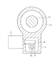
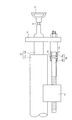
図1は、本発明による電動テレスコ調整式ステアリング装置を組付けた車両を示す全体構成図、図2は本発明による電動テレスコ調整式ステアリング装置の第1の実施形態を示す全体構成図、図3は図2のA−A線上の断面図、図4は図3のB−B線上の断面図、図5は本発明の要部の断面図、図6は図5のC−C線上の断面図、図7は図5のD−D線上の断面図、図8は収縮状態を示す図5と同様の断面図である。
Hereinafter, embodiments of the present invention will be described with reference to the drawings.
FIG. 1 is an overall configuration diagram showing a vehicle assembled with an electric telescopic adjustment type steering device according to the present invention, FIG. 2 is an overall configuration diagram showing a first embodiment of an electric telescopic adjustment type steering device according to the present invention, and FIG. Is a cross-sectional view taken along line AA in FIG. 2, FIG. 4 is a cross-sectional view taken along line BB in FIG. 3, FIG. 5 is a cross-sectional view of the main part of the present invention, and FIG. 7 is a cross-sectional view taken along the line DD of FIG. 5, and FIG. 8 is a cross-sectional view similar to FIG.

図1において、ステアリングコラム装置10は、ステアリングシャフト11を回動自在に支持するステアリングコラム12を有する。ステアリングシャフト11には、その後端にステアリングホイール13が装着され、ステアリングシャフト11の前端にはユニバーサルジョイント14を介して中間シャフト15が連結されている。中間シャフト15にはその前端にユニバーサルジョイント16を介してラックアンドピニオン機構等からなるステアリングギヤ17が連結されている。このステアリングギヤ17の出力軸がタイロッド18を介して転舵輪19に連結されている。   In FIG. 1, a steering column device 10 includes a steering column 12 that supports a steering shaft 11 so as to be rotatable. A steering wheel 13 is mounted at the rear end of the steering shaft 11, and an intermediate shaft 15 is connected to the front end of the steering shaft 11 via a universal joint 14. A steering gear 17 composed of a rack and pinion mechanism or the like is connected to the intermediate shaft 15 via a universal joint 16 at its front end. The output shaft of the steering gear 17 is connected to the steered wheel 19 through a tie rod 18.

そして、運転者がステアリングホイール13を操舵すると、ステアリングシャフト11、ユニバーサルジョイント14、中間シャフト15、ユニバーサルジョイント16を介してその回転力がステアリングギヤ17に伝達され、ラックアンドピニオン機構で回転運動が車両幅方向の直線運動に変換されてタイロッド18を介して転舵輪19を転舵する。
なお、ステアリングコラム12の車両後方部位には、後述する電動チルト機構30及び電動テレスコ機構50を駆動するコンビスイッチやコラムカバー等の周辺部品Pが配設されている。
When the driver steers the steering wheel 13, the rotational force is transmitted to the steering gear 17 via the steering shaft 11, the universal joint 14, the intermediate shaft 15, and the universal joint 16, and the rack and pinion mechanism rotates the vehicle. The steered wheel 19 is steered through the tie rod 18 after being converted into a linear motion in the width direction.
In addition, peripheral components P such as a combination switch and a column cover for driving an electric tilt mechanism 30 and an electric telescopic mechanism 50, which will be described later, are disposed in the vehicle rear portion of the steering column 12.

ステアリングコラム装置10は、図5に示すように、車両の水平方向に対して後ろ上がりに所定角度θだけ傾斜して配置されている。このステアリングコラム装置10はステアリングシャフト11が図5に示すようにステアリングホイール13を取付けたアウタシャフト11aと、このアウタシャフト11aにスプライン結合又はセレーション結合されて摺動自在に係合されたインナシャフト11bとで構成されている。   As shown in FIG. 5, the steering column device 10 is disposed so as to be inclined backward by a predetermined angle θ with respect to the horizontal direction of the vehicle. As shown in FIG. 5, the steering column device 10 includes an outer shaft 11a to which a steering wheel 13 is attached as shown in FIG. 5, and an inner shaft 11b that is slidably engaged with the outer shaft 11a by spline coupling or serration coupling. It consists of and.

また、ステアリングコラム12が図2及び図5に示すようにアウタコラム12aと、このアウタコラム12aに摺動自在に保持されたインナコラム12bとで構成され、インナコラム12bの前後両端部内周面に配設された転がり軸受12c、12dによってステアリングシャフト11のアウタシャフト11aが回転自在に支持されている。
アウタコラム12aはそのユニバーサルジョイント14側の後端(図2において左端)が車体側部材21に取付けられたロアブラケット22にピボットピン23によって上下方向に揺動自在に支持され、ステアリングホイール13側の前端(図2において右端)が車体側部材21に取付けられアッパブラケット24に上下方向に移動自在に支持されている。
As shown in FIGS. 2 and 5, the steering column 12 includes an outer column 12a and an inner column 12b slidably held by the outer column 12a. The outer shaft 11a of the steering shaft 11 is rotatably supported by the arranged rolling bearings 12c and 12d.
The outer column 12a has a rear end (left end in FIG. 2) on the side of the universal joint 14 supported by a lower bracket 22 attached to the vehicle body side member 21 so as to be swingable in the vertical direction by a pivot pin 23. A front end (right end in FIG. 2) is attached to the vehicle body side member 21 and is supported by the upper bracket 24 so as to be movable in the vertical direction.

このアッパブラケット24は、図3に示すように、車体側部材21に取付けられる中央部が上方に膨出された膨出部24aを有する取付板部24bと、この取付板部24bの膨出部24aの左右位置から下方に延長する案内板部24c及び24dと、これら案内板部24c及び24dの下端部間を連結する底板部24eとで方形枠状に形成されている。
そして、アッパブラケット24の取付板部24b、案内板部24c,24d及び底板部24eで囲まれる案内空間24f内に前述したアウタコラム12aが挿通されている。アウタコラム12aは、図3で明らかなように、水平方向に突出する突出部があり、その端部が案内板部24c及び24dと近接対向する垂直の案内面12cを有する案内板部12d,12eが形成されている。
As shown in FIG. 3, the upper bracket 24 includes a mounting plate portion 24b having a bulging portion 24a with a central portion bulging upward attached to the vehicle body side member 21, and a bulging portion of the mounting plate portion 24b. The guide plate portions 24c and 24d extending downward from the left and right positions of 24a and the bottom plate portion 24e connecting the lower ends of the guide plate portions 24c and 24d are formed in a rectangular frame shape.
The outer column 12a described above is inserted into the guide space 24f surrounded by the mounting plate portion 24b, the guide plate portions 24c and 24d, and the bottom plate portion 24e of the upper bracket 24. As is apparent from FIG. 3, the outer column 12a has a protruding portion that protrudes in the horizontal direction, and its end portion has guide plate portions 12d and 12e each having a vertical guide surface 12c that is closely opposed to the guide plate portions 24c and 24d. Is formed.

そして、案内板部12eが電動チルト機構30によって上下方向に移動可能に保持されている。電動チルト機構30は、図3に示すように、アッパブラケット24の案内板部24dの下端部に一体に形成された略方形枠状のギヤハウジング31内に抑え部材32によって固定配置した転がり軸受33と、前述したアッパブラケット24の取付板部24bの下面に配設した転がり軸受34とによって案内板部24dに沿って上下方向に延長し、且つ回転自在に支持されたねじ軸35を有する。   The guide plate portion 12e is held by the electric tilt mechanism 30 so as to be movable in the vertical direction. As shown in FIG. 3, the electric tilt mechanism 30 is a rolling bearing 33 fixedly arranged by a restraining member 32 in a substantially rectangular frame-shaped gear housing 31 formed integrally with the lower end portion of the guide plate portion 24 d of the upper bracket 24. And a screw shaft 35 that extends in the vertical direction along the guide plate portion 24d and is rotatably supported by the rolling bearing 34 disposed on the lower surface of the mounting plate portion 24b of the upper bracket 24 described above.

このねじ軸35には、ギヤハウジング31内の転がり軸受33近傍位置にウォームホイール36が装着され、このウォームホイール36にウォーム37が噛合されている。このウォーム37は、図4に示すように、ギヤハウジング31内に配設された転がり軸受38及び39によって回転自在に保持され、その一端が、アッパブラケット24の案内板部24dに形成された取付板部24gに固定された電動モータ40の出力軸40aにカップリング39を介して連結されている。   A worm wheel 36 is mounted on the screw shaft 35 in the vicinity of the rolling bearing 33 in the gear housing 31, and a worm 37 is engaged with the worm wheel 36. As shown in FIG. 4, the worm 37 is rotatably held by rolling bearings 38 and 39 disposed in the gear housing 31, and one end of the worm 37 is attached to the guide plate portion 24 d of the upper bracket 24. The output shaft 40a of the electric motor 40 fixed to the plate portion 24g is connected via a coupling 39.

また、ギヤハウジング31のねじ軸35を挿通する挿通孔31a内にねじ軸35を覆う円筒覆体41が配設され、この円筒覆体41の先端にねじ軸35の外周面に摺接する大きな弾性を有するポリウレタン等の合成樹脂で製作されたリップ42が配設されている。同様に、転がり軸受34の下端面にもねじ軸35の外周面に摺接するリップ43が配設されている。   A cylindrical cover 41 that covers the screw shaft 35 is disposed in an insertion hole 31 a through which the screw shaft 35 of the gear housing 31 is inserted, and a large elasticity that slides on the outer peripheral surface of the screw shaft 35 at the tip of the cylindrical cover 41. A lip 42 made of a synthetic resin, such as polyurethane, is provided. Similarly, a lip 43 slidably contacting the outer peripheral surface of the screw shaft 35 is also provided on the lower end surface of the rolling bearing 34.

そして、ねじ軸35のリップ42及び43間に、断面方形のナットホルダ44に保持されたナット45が螺合されている。このナットホルダ44はアッパブラケット24の案内板部24dに形成された上下方向に延長する案内溝46内に係合することにより、ナットホルダ44のねじ軸35における軸芯回りの回転運動が規制され、ねじ軸35の正逆回転によってナットホルダ44が上下方向に移動される。このナットホルダ44に突出形成された係合ピン47が前述したアウタコラム12aの先端に形成されたアウタコラム12aの軸方向に延長する長孔24hに係合されている。   A nut 45 held by a nut holder 44 having a square cross section is screwed between the lips 42 and 43 of the screw shaft 35. The nut holder 44 engages in a guide groove 46 formed in the guide plate portion 24d of the upper bracket 24 and extending in the vertical direction, so that the rotational movement around the axis of the screw shaft 35 of the nut holder 44 is restricted. The nut holder 44 is moved in the vertical direction by forward and reverse rotation of the screw shaft 35. An engaging pin 47 protruding from the nut holder 44 is engaged with a long hole 24h extending in the axial direction of the outer column 12a formed at the tip of the outer column 12a.

したがって、電動モータ40によってウォーム37を正逆転駆動することにより、ウォームホイール36を介してねじ軸35が正逆転駆動され、これによってナットホルダ44が上下動され、アウタコラム12aがピボットピン23を中心として上下に揺動されてチルト機能を発揮することができる。
そして、ステアリングコラム12のアウタコラム12a及びインナコラム12b間に図5に示すように電動アクチュエータとしての電動テレスコ機構50が設けられている。
Therefore, when the worm 37 is driven forward / reversely by the electric motor 40, the screw shaft 35 is driven forward / reversely via the worm wheel 36, whereby the nut holder 44 is moved up and down, and the outer column 12a is centered on the pivot pin 23. As a result, the tilt function can be exerted.
An electric telescopic mechanism 50 as an electric actuator is provided between the outer column 12a and the inner column 12b of the steering column 12 as shown in FIG.

この電動テレスコ機構50は、図5に示すように、ステアリングコラム12のアウタコラム12aのステアリングホイール13側に固定されたギヤハウジング51を有する。このギヤハウジング51には、ステアリングコラム12の軸方向に所定距離だけ離れて対向配置された転がり軸受52及び53によってウォームホイール54が回転自在に支持されている。このウォームホイール54は、中央部の大径外周面とこの大径外周面を挟む両端側の転がり軸受52及び53が外嵌された小径外周面とを有する円筒状に形成され、大径外周面にヘリカルギヤ54aが形成されていると共に、内周面に雌ねじ54bが形成されている。   As shown in FIG. 5, the electric telescopic mechanism 50 includes a gear housing 51 fixed to the steering wheel 13 side of the outer column 12 a of the steering column 12. A worm wheel 54 is rotatably supported on the gear housing 51 by rolling bearings 52 and 53 that are arranged to face each other at a predetermined distance in the axial direction of the steering column 12. The worm wheel 54 is formed in a cylindrical shape having a large-diameter outer peripheral surface at the center and small-diameter outer peripheral surfaces fitted with rolling bearings 52 and 53 on both ends sandwiching the large-diameter outer peripheral surface. In addition, a helical gear 54a is formed, and a female screw 54b is formed on the inner peripheral surface.

そして、ウォームホイール54のヘリカルギヤ54aには、図6に示すように、ギヤハウジング51に取付けられた電動モータ55の出力軸に連結されたウォーム56が噛合され、これらウォームホイール54及びウォーム56でウォーム減速機構が構成されている。また、後述する連結ロッド58とウォームホイール54の雌ねじ54bとで直動機構が構成されている。   As shown in FIG. 6, a worm 56 connected to an output shaft of an electric motor 55 attached to the gear housing 51 is engaged with the helical gear 54 a of the worm wheel 54. A deceleration mechanism is configured. Further, a linear motion mechanism is constituted by a connecting rod 58 and a female screw 54b of the worm wheel 54 described later.

一方、ステアリングコラム12のインナコラム12bのステアリングホイール13寄り位置にギヤハウジング51と同一方向に延長し且つアウタコラム12aの端面とは距離をおいて配置された連結プレート57が取付けられ、この連結プレート57とギヤハウジング51との間にステアリングコラム12の中心軸と所定オフセット量Lを保って平行な連結ロッド58が配設されている。   On the other hand, a connecting plate 57 that extends in the same direction as the gear housing 51 and is disposed at a distance from the end surface of the outer column 12a is attached to a position near the steering wheel 13 of the inner column 12b of the steering column 12. A connecting rod 58 parallel to the center axis of the steering column 12 and a predetermined offset amount L is disposed between the gear housing 51 and the gear housing 51.

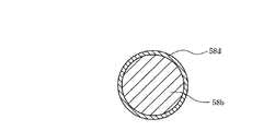
この連結ロッド58は、一端が連結プレート57の下端に取付けられたアウタロッド58aと、このアウタロッド58aの他端に摺動自在に係合されたインナロッド58bとで構成され、両者の接合部が収縮部とされている。
これらアウタロッド58a及びインナロッド58bとの接合部には、通常時の運転者などの人力によってはアウタロッド58a及びインナロッド58b間の相対移動を規制するが、二次衝突時に衝撃荷重がステアリングホイール13、インナコラム12b、連結プレート57を介してアウタロッド58aに伝達されたときには、アウタロッド58a及びインナロッド58b間の相対移動を許容する衝撃吸収部材60が配設されている。
The connecting rod 58 includes an outer rod 58a having one end attached to the lower end of the connecting plate 57 and an inner rod 58b slidably engaged with the other end of the outer rod 58a. It is considered to be a part.
At the joint between the outer rod 58a and the inner rod 58b, the relative movement between the outer rod 58a and the inner rod 58b is restricted depending on human power such as a normal driver. An impact absorbing member 60 that allows relative movement between the outer rod 58a and the inner rod 58b when being transmitted to the outer rod 58a via the inner column 12b and the connecting plate 57 is disposed.

この衝撃吸収部材60は断面が周方向に凹凸を繰り返す波形に成形された薄い板バネ材をリング状に形成した構成を有し、アウタロッド58a及びインナロッド58bの相対移動を許容するコラプス荷重が例えば約2kN以上に設定されている。
そして、インナロッド58b及び衝撃吸収部材60と摺接する外周面に例えば二硫化モリブデン系、フッ素樹脂系の固体潤滑剤の被膜58dが形成されている。
The shock absorbing member 60 has a configuration in which a thin leaf spring material having a cross-sectional shape that is concave and convex in the circumferential direction is formed in a ring shape, and a collapse load that allows relative movement of the outer rod 58a and the inner rod 58b is, for example, It is set to about 2 kN or more.
A coating 58d of, for example, molybdenum disulfide-based or fluororesin-based solid lubricant is formed on the outer peripheral surface that is in sliding contact with the inner rod 58b and the impact absorbing member 60.

また、インナロッド58bはそのアウタロッド58a側とは反対側に雄ねじ58cが形成され、この雄ねじ58cがギヤハウジング51に回転自在に支持されたウォームホイール54の雌ねじ54bに螺合されて、連結ロッド58がステアリングコラム12の軸方向と平行となるように配設されている。
したがって、電動モータ55を正逆転駆動することにより、ウォーム56を介してウォームホイール54を正逆転駆動することにより、インナロッド58bがステアリングコラム12の軸方向に前後進することにより、アウタロッド58a及び連結プレート57を介してインナコラム12bが軸方向に伸縮駆動されてテレスコ機能を発揮することができる。
The inner rod 58b is formed with a male screw 58c on the side opposite to the outer rod 58a. The male screw 58c is screwed into a female screw 54b of a worm wheel 54 rotatably supported by the gear housing 51, thereby connecting rod 58b. Is arranged so as to be parallel to the axial direction of the steering column 12.
Therefore, by driving the electric motor 55 forward / reversely, driving the worm wheel 54 forward / reversely via the worm 56, and moving the inner rod 58 b back and forth in the axial direction of the steering column 12, the outer rod 58 a and the connection The inner column 12b is driven to extend and contract in the axial direction via the plate 57, so that a telescopic function can be exhibited.

次に、上記第1の実施形態の動作を説明する。
今、運転者が、ステアリングコラム装置10のステアリングコラム12のチルト調整を行うには、図1に示すステアリングコラム12の車両後方部位に配設された周辺部品Pに設けられたチルト機構用のコンビスイッチをチルトアップ方向(又はチルトダウン方向)に操作すると、電動チルト機構30の電動モータ40を例えば正転(又は逆転)駆動される。
Next, the operation of the first embodiment will be described.
Now, in order for the driver to adjust the tilt of the steering column 12 of the steering column device 10, the combination for the tilt mechanism provided in the peripheral part P provided in the vehicle rear portion of the steering column 12 shown in FIG. When the switch is operated in the tilt-up direction (or tilt-down direction), the electric motor 40 of the electric tilt mechanism 30 is driven forward (or reverse), for example.

これに応じて、ウォーム37を介してウォームホイール36を介してねじ軸35を逆転(又は正転)駆動することにより、ナット45が図3で見て上方(又は下方)に移動し、これによってナットホルダ44に形成された係合ピン47がステアリングコラム12のアウタコラム12aに形成された長孔24hに係合しているので、アウタコラム12aがピボットピン23を中心として上方(下方)に回動し、チルトアップ(又はチルトダウン)調整を行うことができる。   In response to this, by driving the screw shaft 35 in reverse (or forward) via the worm 37 via the worm 37, the nut 45 moves upward (or downward) as viewed in FIG. Since the engaging pin 47 formed on the nut holder 44 is engaged with the long hole 24h formed on the outer column 12a of the steering column 12, the outer column 12a rotates upward (downward) about the pivot pin 23. And tilt up (or tilt down) adjustment.

また、運転者が、ステアリングコラム装置10のステアリングコラム12のテレスコ調整を行うには、図1に示すステアリングコラム12の車両後方部位に配設された周辺部品Pに設けられたテレスコ機構用コンビスイッチを伸張方向(又は収縮方向)に操作すると、電動テレスコ機構50の電動モータ55が例えば正転(又は逆転)駆動される。
これによって、ウォーム56を介してウォームホイール54が正転(又は逆転)駆動され、これによって連結ロッド58のインナロッド58bがステアリングホイール13側(又はステアリングホイール13とは反対側)に移動し、衝撃吸収部材60を介してアウタロッド58aがステアリングホイール13側(又はステアリングホイール13とは反対側)に移動する。
In addition, in order for the driver to perform telescopic adjustment of the steering column 12 of the steering column device 10, a telescopic mechanism combination switch provided in a peripheral part P disposed in the rear portion of the steering column 12 shown in FIG. Is operated in the expansion direction (or contraction direction), the electric motor 55 of the electric telescopic mechanism 50 is driven forward (or reverse), for example.
As a result, the worm wheel 54 is driven to rotate forward (or reversely) through the worm 56, whereby the inner rod 58 b of the connecting rod 58 moves to the steering wheel 13 side (or the side opposite to the steering wheel 13), and the impact The outer rod 58a moves to the steering wheel 13 side (or the side opposite to the steering wheel 13) via the absorbing member 60.

このため、連結プレート57を介してインナコラム12bがアウタコラム12aから引き出されて(又はインナコラム12bがアウタコラム12a内に挿入されて)ステアリングコラム12が伸張(又は収縮)してテレスコ調整を行うことができる。
このとき、インナコラム12bの移動に伴って、ステアリングシャフト11のアウタシャフト11aがインナシャフト11bに対して移動する。
For this reason, the inner column 12b is pulled out from the outer column 12a via the connecting plate 57 (or the inner column 12b is inserted into the outer column 12a), and the steering column 12 is expanded (or contracted) to perform telescopic adjustment. be able to.
At this time, along with the movement of the inner column 12b, the outer shaft 11a of the steering shaft 11 moves relative to the inner shaft 11b.

このように、電動テレスコ機構50によって、ステアリングコラム12を伸縮させてテレスコ調整を行うことができるものであるが、連結ロッド58を電動モータ55で移動させる場合には衝撃吸収部材60がアウタロッド58a及びインナロッド58b間の伸縮を確実に防止して、アウタロッド58a及びインナロッド58bが一体となって連結プレート57を車両前後方向に移動させて、インナコラム12bを車両前後方向に移動させることができる。   As described above, the telescopic adjustment can be performed by expanding and contracting the steering column 12 by the electric telescopic mechanism 50. However, when the connecting rod 58 is moved by the electric motor 55, the impact absorbing member 60 is provided with the outer rod 58a and the outer rod 58a. Expansion and contraction between the inner rods 58b can be reliably prevented, and the outer rod 58a and the inner rod 58b can be integrated to move the connecting plate 57 in the vehicle longitudinal direction, and the inner column 12b can be moved in the vehicle longitudinal direction.

しかしながら、二次衝突によってステアリングホイール13に車両水平方向で前方側即ち図5で左方に押圧する衝撃荷重Fが作用すると、先ず、この衝撃荷重Fがコラム軸方向分力Fxとコラム軸直角方向分力Fyとに分力される。そして、コラム軸方向分力Fxによってインナコラム12b及びアウタシャフト11aが図5で見てコラム軸方向左側に押され、これに応じて連結プレート57を介して連結ロッド58のアウタロッド58aが左方に移動されて衝撃吸収部材60にコラム軸方向分力Fxが伝達される。そして、この衝撃吸収部材60に伝達されるコラム軸方向分力Fxが設定されたコラプス荷重に達すると、衝撃吸収部材60でアウタロッド58aとインナロッド58bとの相対移動を許容してアウタロッド58a内にインナロッド58bが挿入されて図8に示すように所定のコラプスストロークを確保することができる。   However, when an impact load F is applied to the steering wheel 13 in the horizontal direction of the vehicle due to the secondary collision, the impact load F is first applied to the column axis direction component force Fx and the column axis direction perpendicular to the column axis direction. It is divided into component force Fy. Then, the inner column 12b and the outer shaft 11a are pushed to the left in the column axial direction as viewed in FIG. 5 by the column axial component force Fx, and the outer rod 58a of the connecting rod 58 is moved to the left via the connecting plate 57 accordingly. The column axial component force Fx is transmitted to the shock absorbing member 60 by being moved. When the column axial component force Fx transmitted to the shock absorbing member 60 reaches a set collapse load, the shock absorbing member 60 allows the outer rod 58a and the inner rod 58b to move relative to each other and enters the outer rod 58a. The inner rod 58b is inserted to ensure a predetermined collapse stroke as shown in FIG.

このように、ステアリングホイール13に車両前方に移動させる衝撃荷重が作用したときに、コラム軸方向分力Fxがコラプス荷重に達するまでの間では、ステアリングコラム12のアウタコラム12a及びインナコラム12b間での摺動抵抗は僅かであり、連結ロッド58のアウタロッド58a及びインナロッド58b間は衝撃吸収部材60で滑りが無い状態に保持されている。   In this way, when an impact load for moving the vehicle forward is applied to the steering wheel 13, until the column axial component force Fx reaches the collapse load, between the outer column 12 a and the inner column 12 b of the steering column 12. The sliding resistance of the connecting rod 58 is kept slight between the outer rod 58a and the inner rod 58b of the connecting rod 58 by the shock absorbing member 60.

しかしながら、衝撃吸収部材60位置に伝達されるコラム軸方向分力Fxがコラプス荷重以上となると、衝撃吸収部材60でアウタロッド58a及びインナロッド58bの相対移動を許容することにより、アウタロッド58a内にインナロッド58bが徐々に挿入されて、連結ロッド58が収縮する。この際、衝撃吸収部材60によってインナロッド58bに対して所定の荷重を与えながらインナロッド58bがアウタロッド58a内に挿入されるので、衝撃エネルギーを吸収することができる。このとき、インナロッド58bの衝撃吸収部材60に摺接する外周面に固体潤滑剤の被膜58dが形成されているので、インナロッド58bがアウタロッド58a内に挿入される過程で、固体潤滑剤の被膜58dが掻きだされることがなく、衝撃吸収部材60とインナロッド58bとの間の接触面に固体潤滑剤被膜58dが常に存在することになり、衝撃吸収部材60とインナロッド58bとの間の潤滑を良好に行うことができる。このため、衝撃吸収部材60とインナロッド58bとが相対移動する際に、荷重が安定すると共に、スティックスリップの発生を防止することができ、衝撃エネルギーの吸収を安定して行うことができる。   However, when the column axial component force Fx transmitted to the position of the shock absorbing member 60 becomes equal to or greater than the collapse load, the shock absorbing member 60 allows the outer rod 58a and the inner rod 58b to move relative to each other, thereby allowing the inner rod 58a to move into the inner rod 58a. 58b is gradually inserted, and the connecting rod 58 contracts. At this time, since the inner rod 58b is inserted into the outer rod 58a while applying a predetermined load to the inner rod 58b by the shock absorbing member 60, the impact energy can be absorbed. At this time, since the coating film 58d of the solid lubricant is formed on the outer peripheral surface of the inner rod 58b that is in sliding contact with the shock absorbing member 60, the coating film 58d of the solid lubricant is inserted in the process of inserting the inner rod 58b into the outer rod 58a. The solid lubricant film 58d is always present on the contact surface between the shock absorbing member 60 and the inner rod 58b, and the lubrication between the shock absorbing member 60 and the inner rod 58b. Can be performed satisfactorily. For this reason, when the impact absorbing member 60 and the inner rod 58b move relative to each other, the load is stabilized, the occurrence of stick-slip can be prevented, and the impact energy can be absorbed stably.

一方、衝撃荷重Fのコラム軸直角方向分力Fyによって、インナコラム12b及びアウタシャフト11aが上方向に僅かに撓まされ、インナコラム12bに剛結された連結プレート57もインナコラム12bと直角を保ったまま一緒に移動される。その結果、連結プレート57を介して連結ロッド58のアウタロッド58a及びインナロッド58b間にこじりが発生するが、インナロッド58bに固体潤滑剤被膜58dが形成されているので、こじりによる潤滑状態の変化を抑制し、所定荷重で安定した相対移動を確保することができ、衝撃エネルギーの吸収を安定して行うことができる。   On the other hand, the inner column 12b and the outer shaft 11a are slightly bent upward by the component force Fy in the direction perpendicular to the column axis of the impact load F, and the connecting plate 57 rigidly connected to the inner column 12b is also perpendicular to the inner column 12b. Moved together while keeping. As a result, a twisting occurs between the outer rod 58a and the inner rod 58b of the connecting rod 58 via the connecting plate 57. However, since the solid lubricant film 58d is formed on the inner rod 58b, the change in the lubrication state due to the twisting is prevented. Stable relative movement with a predetermined load can be secured, and impact energy can be absorbed stably.

なお、上記実施形態においては、連結ロッド58のインナロッド58bに固体潤滑剤の被膜58dを形成した場合について説明したが、これに限定されるものではなく、アウタロッド58aの内周面に固体潤滑剤の被膜を形成するようにしてもよく、アウタロッド58aの内周面及びインナロッド58bの外周面の双方に固体潤滑剤の被膜を形成するようにしてもよい。さらには、衝撃吸収部材60の内周面又は外周面にも固体潤滑材の被膜を形成するようにしてもよい。   In the above-described embodiment, the case where the coating film 58d of the solid lubricant is formed on the inner rod 58b of the connecting rod 58 has been described. However, the present invention is not limited to this, and the solid lubricant is formed on the inner peripheral surface of the outer rod 58a. A film of solid lubricant may be formed on both the inner peripheral surface of the outer rod 58a and the outer peripheral surface of the inner rod 58b. Further, a solid lubricant film may be formed on the inner peripheral surface or the outer peripheral surface of the shock absorbing member 60.

また、上記実施形態においては、ステアリングコラム12のアウタコラム12aを車体側部材21に固定した場合について説明したが、これに限定されるものではなく、インナコラム12bをロアブラケット22及びアッパブラケット24で車体側部材21に取付け、アウタコラム12a側にステアリングホイール13を取付けるようにしてもよい。   In the above embodiment, the case where the outer column 12a of the steering column 12 is fixed to the vehicle body side member 21 has been described. However, the present invention is not limited to this, and the inner column 12b is formed by the lower bracket 22 and the upper bracket 24. The steering wheel 13 may be attached to the vehicle body side member 21 and the outer column 12a side.

さらに、上記実施形態においては、連結ロッド58のアウタロッド58aを連結プレート57に直接固定した場合について説明したが、これに限定されるものではなく、連結ロッドのアウタロッド58aと連結プレート57とをピポットピンを介して連結するようにしてもよい。この場合には、インナコラム12bにコラム軸方向分力Fxが作用したときに、連結プレート57に発生する連結ロッド58にこじりを与える曲げモーメントが連結ロッド58に影響することを確実に防止することができ、コラム軸方向分力Fxがコラプス荷重以上となったときに連結ロッド58のアウタロッド58a及びインナロッド58b間の相対移動をより安定させることができ、より良好な衝撃エネルギー吸収を行うことができる。   Furthermore, in the above embodiment, the case where the outer rod 58a of the connecting rod 58 is directly fixed to the connecting plate 57 has been described. However, the present invention is not limited to this, and the pipe rod is connected to the outer rod 58a of the connecting rod and the connecting plate 57. You may make it connect via. In this case, when the column axial component force Fx is applied to the inner column 12b, it is possible to reliably prevent the bending moment that twists the connecting rod 58 generated in the connecting plate 57 from affecting the connecting rod 58. When the column axial component force Fx becomes equal to or greater than the collapse load, the relative movement between the outer rod 58a and the inner rod 58b of the connecting rod 58 can be further stabilized, and better impact energy absorption can be performed. it can.

さらにまた、上記実施形態においては、アウタロッド58a及びインナロッド58bを断面波形のリング状に形成した衝撃吸収部材60で連結する場合について説明したが、衝撃吸収部材60としては上記構成とする場合に限らず、設定されたコラプス荷重以上の衝撃荷重が伝達されたときに、アウタロッド58a及びインナロッド58bを相対移動させるものであれば任意の構成を適用することができ、例えばステアリング装置の側面図を表す図9に示すように、連結ロッド58のアウタロッド58a及びインナロッド58bの接合部に両者を貫通する合成樹脂製のピン61を圧入し、このピン61を二次衝突荷重によるコラム軸方向分力Fxがコラプス荷重以上となったときに破断してコラプスさせるように構成し、連結ロッド58のインナロッド58bのアウタロッド58aと摺接する外周面に固体潤滑剤の被膜58dを形成するようにしてもよい。この場合も、コラム軸方向分力Fxがコラプス荷重以上になってアウタロッド58a内にインナロッド58bが挿入される状態となったときに、両者間に潤滑剤被膜58dが必ず存在することになり、所定荷重を与えながら安定した相対移動を確保して良好な衝撃エネルギー吸収を行うことができる。また、固体潤滑剤の被膜はアウタロッド58aの内周面に形成するようにしてもよく、アウタロッド58aの内周面及びインナロッド58bの外周面の双方に形成するようにしてもよい。   Furthermore, in the above embodiment, the case where the outer rod 58a and the inner rod 58b are connected by the shock absorbing member 60 formed in a ring shape having a corrugated cross section has been described. However, the shock absorbing member 60 is limited to the above configuration. Any configuration can be applied as long as the outer rod 58a and the inner rod 58b are relatively moved when an impact load equal to or greater than the set collapse load is transmitted. For example, a side view of the steering device is shown. As shown in FIG. 9, a synthetic resin pin 61 passing through both the outer rod 58a and the inner rod 58b of the connecting rod 58 is press-fitted, and this pin 61 is subjected to a column axial component force Fx caused by a secondary collision load. Is configured to break and collapse when the load exceeds the collapse load. It may be formed a film 58d of the solid lubricant on the outer circumferential surface of the outer rod 58a in sliding contact of Naroddo 58b. Also in this case, when the column axial component force Fx becomes equal to or greater than the collapse load and the inner rod 58b is inserted into the outer rod 58a, the lubricant film 58d always exists between the two. Stable relative movement can be ensured while applying a predetermined load, and good impact energy absorption can be performed. The solid lubricant coating may be formed on the inner peripheral surface of the outer rod 58a, or may be formed on both the inner peripheral surface of the outer rod 58a and the outer peripheral surface of the inner rod 58b.

なおさらに、上記実施形態においては、連結ロッド58にアウタロッド58a及びインナロッド58bによって構成される収縮部を形成する場合について説明したが、これに限定されるものではなく、ステアリング装置の断面図を表す図10に示すように、連結プレート57をインナコラム12bから下方に延長する取付部57aと、この取付部57aの下端から車両前方側にステアリングコラム12の中心軸と平行に延長する中間部57bと、この中間部57bの前端から下方に延長する支持部57cとでクランク状に形成し、支持部57cに連結ロッド58を挿通する挿通孔57dを形成し、この挿通孔57d内に前述した衝撃吸収部材60と同一構成を有する衝撃吸収部材62を配設して止めナット63で固定する構成とする一方、連結ロッド58を、小径ロッド部58fと大径ロッド部58gとを一体に形成した構成とし、小径ロッド部58fに雄ねじを形成してウォームホイール54の雌ねじ54bと螺合させ、大径ロッド部58gを連結プレート57の挿通孔57dに挿通させるようにしてもよい。この場合も、連結ロッド58の大径ロッド部58gにおける連結プレート57の挿通孔57dと摺接する外周面に固体潤滑剤の被膜58hを形成することにより、連結プレート57に伝達される二次衝突荷重によるコラム軸方向分力Fxがコラプス荷重以上となると衝撃吸収部材62によって連結ロッド58と連結プレート57との相対移動が許容されることにより、連結ロッド58の大径ロッド部58gが連結プレート57の挿通孔57dに挿入されて連結プレート57の車両前方への移動が許容される。このときに、衝撃吸収部材62と連結ロッド58の大径ロッド部58gとの間に常に固体潤滑剤の被膜58hが存在するので、連結プレート57の移動を、所定荷重を与えながら円滑に行うことができ、安定した衝撃エネルギーの吸収を行うことができる。
さらに、上記実施形態においては、電動チルト機構30を備えている場合について説明したが、これに限定されるものではなく、電動チルト機構30を省略して、電動テレスコ機構50のみを設けるようにしてもよい。
Furthermore, in the above-described embodiment, the case where the connecting rod 58 is formed with the contracted portion constituted by the outer rod 58a and the inner rod 58b has been described. However, the present invention is not limited to this, and represents a cross-sectional view of the steering device. As shown in FIG. 10, a mounting portion 57a that extends the connecting plate 57 downward from the inner column 12b, and an intermediate portion 57b that extends from the lower end of the mounting portion 57a to the front side of the vehicle in parallel with the central axis of the steering column 12. The intermediate portion 57b is formed in a crank shape with the support portion 57c extending downward from the front end, and the support portion 57c is formed with an insertion hole 57d through which the connecting rod 58 is inserted. The shock absorption described above is formed in the insertion hole 57d. An impact absorbing member 62 having the same configuration as that of the member 60 is disposed and fixed with a locking nut 63, while The rod 58 has a configuration in which a small-diameter rod portion 58f and a large-diameter rod portion 58g are integrally formed. A male screw is formed on the small-diameter rod portion 58f and is screwed with the female screw 54b of the worm wheel 54. You may make it insert in the insertion hole 57d of the connection plate 57. FIG. Also in this case, the secondary collision load transmitted to the connecting plate 57 is formed by forming the solid lubricant film 58h on the outer peripheral surface of the connecting rod 58 that is in sliding contact with the insertion hole 57d of the connecting plate 57 in the large-diameter rod portion 58g. When the column axial component force Fx is greater than or equal to the collapse load, the shock absorbing member 62 allows relative movement between the connecting rod 58 and the connecting plate 57, so that the large-diameter rod portion 58 g of the connecting rod 58 is connected to the connecting plate 57. The connection plate 57 is inserted into the insertion hole 57d and allowed to move forward of the vehicle. At this time, since the solid lubricant film 58h always exists between the shock absorbing member 62 and the large-diameter rod portion 58g of the connecting rod 58, the connecting plate 57 is smoothly moved while applying a predetermined load. And stable absorption of impact energy can be performed.
Furthermore, although the case where the electric tilt mechanism 30 is provided has been described in the above embodiment, the present invention is not limited to this, and the electric tilt mechanism 30 is omitted and only the electric telescopic mechanism 50 is provided. Also good.

本発明によるステアリング装置を車両に搭載した状態を示す全体構成図である。1 is an overall configuration diagram illustrating a state in which a steering device according to the present invention is mounted on a vehicle. ステアリングコラム装置のステアリングホイールを除いた側面図である。It is a side view except a steering wheel of a steering column device. 図2のA−A線上の断面図である。It is sectional drawing on the AA line of FIG. 図3のB−B線上の断面図である。It is sectional drawing on the BB line of FIG. ステアリングコラム装置の要部の縦断面図である。It is a longitudinal cross-sectional view of the principal part of a steering column apparatus. 図5のC−C線上の断面図である。It is sectional drawing on the CC line of FIG. 図5のD−D線上の断面図である。It is sectional drawing on the DD line of FIG. 収縮時の図5と同様の縦断面図である。It is the longitudinal cross-sectional view similar to FIG. 5 at the time of contraction. 本発明の他の実施形態を示す要部を断面とした側面図である。It is the side view which made the cross section the principal part which shows other embodiment of this invention. 本発明のさらに他の実施形態を示す縦断面図である。It is a longitudinal cross-sectional view which shows other embodiment of this invention.

符号の説明Explanation of symbols

10…ステアリングコラム装置、11…ステアリングシャフト、11a…アウタシャフト、11b…インナシャフト、12…ステアリングコラム、12a…アウタコラム、12b…インナコラム、13…ステアリングホイール、14,16…ユニバーサルジョイント、15…中間シャフト、17…ステアリングギヤ、18…タイロッド、19…転舵輪、21…車体側部材、22…ロアブラケット、24…アッパブラケット、30…チルト機構、50…テレスコ機構、51…ギヤハウジング、54…ウォームホイール、55…電動モータ、56…ウォーム、57…連結プレート、58…連結ロッド、58a…アウタロッド、58b…インナロッド、58d…固体潤滑剤被膜、58f…小径ロッド部、58g…大径ロッド部、58h…固体潤滑剤被膜、60、62…衝撃吸収部材、61……ピン   DESCRIPTION OF SYMBOLS 10 ... Steering column apparatus, 11 ... Steering shaft, 11a ... Outer shaft, 11b ... Inner shaft, 12 ... Steering column, 12a ... Outer column, 12b ... Inner column, 13 ... Steering wheel, 14, 16 ... Universal joint, 15 ... Intermediate shaft, 17 ... steering gear, 18 ... tie rod, 19 ... steering wheel, 21 ... vehicle body side member, 22 ... lower bracket, 24 ... upper bracket, 30 ... tilt mechanism, 50 ... telescopic mechanism, 51 ... gear housing, 54 ... Worm wheel, 55 ... electric motor, 56 ... worm, 57 ... connecting plate, 58 ... connecting rod, 58a ... outer rod, 58b ... inner rod, 58d ... solid lubricant coating, 58f ... small diameter rod portion, 58g ... large diameter rod portion 58h ... Solid lubricant Film, 60, 62 ... shock absorbing member, 61 ...... pin

Claims (5)

相対的に伸縮自在に連結されたアウタコラム及びインナコラムを有し、ステアリングホイールを取付けたステアリングシャフトを回転自在に支持するステアリングコラムと、一方の端部が前記アウタコラムに、他方の端部が前記インナコラムに取付けられ、前記アウタコラム及び前記インナコラムを伸縮させる電動アクチュエータとを備え、前記電動アクチュエータは衝撃荷重が入力されたときに軸方向に所定の荷重を発生しながら収縮して衝撃エネルギーを吸収する収縮部を有する電動テレスコ調整式ステアリング装置であって、
前記電動アクチュエータの収縮部に固体潤滑剤の被膜を形成したことを特徴とする電動テレスコ調整式ステアリング装置。
A steering column that has an outer column and an inner column that are relatively telescopically connected, and that rotatably supports a steering shaft to which a steering wheel is attached, one end of the steering column and the other end An electric actuator attached to the inner column and extending and contracting the outer column and the inner column, and the electric actuator contracts while generating a predetermined load in the axial direction when an impact load is input, An electric telescopic adjustment type steering device having a contraction part that absorbs
An electric telescopic adjustment type steering apparatus, wherein a solid lubricant film is formed on a contraction portion of the electric actuator.
前記電動アクチュエータは、前記インナコラムの中心軸に対して所定のオフセット量を保って平行に配設された電動モータで駆動されるロッドを備えていることを特徴とする請求項1に記載の電動テレスコ調整式ステアリング装置。   The electric actuator according to claim 1, wherein the electric actuator includes a rod driven by an electric motor disposed in parallel with a predetermined offset amount with respect to a central axis of the inner column. Telescopic adjustable steering device. 前記ロッドは、インナロッドと、該インナロッドを所定の隙間を介して相対移動可能に挿通するアウタロッドと、前記インナロッド及び前記アウタロッド間の隙間に嵌挿され且つ内外周面に波形の凹凸が形成されて二次衝突荷重の作用時に所定の荷重を与えながら前記インナロッド及び前記アウタロッドの収縮を許容する衝撃吸収部材とで構成され、前記インナロッド及び前記アウタロッドの少なくとも一方の摺接面に固体潤滑剤の被膜を形成したことを特徴とする請求項2に記載の電動テレスコ調整式ステアリング装置。   The rod is inserted into an inner rod, an outer rod through which the inner rod is inserted so as to be relatively movable through a predetermined gap, and a corrugated unevenness is formed on the inner and outer peripheral surfaces of the inner rod and the outer rod. And a shock absorbing member that allows contraction of the inner rod and the outer rod while applying a predetermined load when a secondary collision load is applied, and solid-lubricating at least one sliding contact surface of the inner rod and the outer rod The electric telescopic adjustment type steering device according to claim 2, wherein a coating of an agent is formed. 前記ロッドは、インナロッドと、該インナロッドを二次衝突荷重の作用時に所定の荷重を与えながら相対移動可能に嵌挿するアウタロッドと、前記インナロッド及び前記アウタロッド間に介装された二次衝突荷重の作用時に破断するピンとで構成され、前記インナロッド及び前記アウタロッドの少なくとも一方の摺接面に固体潤滑剤の被膜を形成したことを特徴とする請求項2に記載の電動テレスコ調整式ステアリング装置。   The rod includes an inner rod, an outer rod that is inserted into the inner rod so as to be relatively movable while applying a predetermined load when a secondary collision load is applied, and a secondary collision interposed between the inner rod and the outer rod. 3. The electric telescopic adjustment type steering apparatus according to claim 2, further comprising a pin that breaks when a load is applied, and a solid lubricant film is formed on at least one sliding contact surface of the inner rod and the outer rod. . 前記ロッドは、一端側が電動モータに連結されたウォーム減速機構のウォームホイール内周面に形成した雌ねじに螺合され、他端側が前記アウタコラム及び前記インナコラムの何れか一方に固定された連結部材に二次衝突荷重の作用時に所定の荷重を与えながら相対移動可能に嵌挿され、前記ロッドの前記連結部材との摺接部に固体潤滑剤の被膜を形成したことを特徴とする請求項2に記載の電動テレスコ調整式ステアリング装置。   The rod is screwed into a female screw formed on the inner peripheral surface of the worm wheel of the worm speed reduction mechanism, one end of which is connected to the electric motor, and the other end is fixed to one of the outer column and the inner column. 3. A solid lubricant film is formed on a sliding contact portion of the rod with the connecting member while applying a predetermined load when a secondary collision load is applied to the rod. The electric telescopic adjustment type steering device described in 1.
JP2006200907A 2006-04-27 2006-07-24 Electric telescopic-adjustment type steering device Pending JP2008024229A (en)

Priority Applications (4)

Application Number Priority Date Filing Date Title
JP2006200907A JP2008024229A (en) 2006-07-24 2006-07-24 Electric telescopic-adjustment type steering device
EP07742313A EP2012025A1 (en) 2006-04-27 2007-04-24 Fastening tool, and steering device
US12/063,257 US20090256341A1 (en) 2006-04-27 2007-04-24 Fastener
PCT/JP2007/058878 WO2007125928A1 (en) 2006-04-27 2007-04-24 Fastening tool, and steering device

Applications Claiming Priority (1)

Application Number Priority Date Filing Date Title
JP2006200907A JP2008024229A (en) 2006-07-24 2006-07-24 Electric telescopic-adjustment type steering device

Publications (1)

Publication Number Publication Date
JP2008024229A true JP2008024229A (en) 2008-02-07

Family

ID=39115303

Family Applications (1)

Application Number Title Priority Date Filing Date
JP2006200907A Pending JP2008024229A (en) 2006-04-27 2006-07-24 Electric telescopic-adjustment type steering device

Country Status (1)

Country Link
JP (1) JP2008024229A (en)

Cited By (5)

* Cited by examiner, † Cited by third party
Publication number Priority date Publication date Assignee Title
JP2009196388A (en) * 2008-02-19 2009-09-03 Nsk Ltd Electric tilt type steering device
JP2013203225A (en) * 2012-03-28 2013-10-07 Showa Corp Steering device
KR101747277B1 (en) * 2014-08-29 2017-06-14 도요타 지도샤(주) Charge reducing device for vehicle
US9909633B2 (en) 2015-02-10 2018-03-06 Toyota Jidosha Kabushiki Kaisha Braking force generation device of vehicle
CN112776872A (en) * 2019-11-06 2021-05-11 操纵技术Ip控股公司 System, method and apparatus for a telescoping lead screw for a steering column

Cited By (6)

* Cited by examiner, † Cited by third party
Publication number Priority date Publication date Assignee Title
JP2009196388A (en) * 2008-02-19 2009-09-03 Nsk Ltd Electric tilt type steering device
JP2013203225A (en) * 2012-03-28 2013-10-07 Showa Corp Steering device
KR101747277B1 (en) * 2014-08-29 2017-06-14 도요타 지도샤(주) Charge reducing device for vehicle
US10384663B2 (en) 2014-08-29 2019-08-20 Toyota Jidosha Kabushiki Kaisha Vehicle electrification charge reducing apparatus
US9909633B2 (en) 2015-02-10 2018-03-06 Toyota Jidosha Kabushiki Kaisha Braking force generation device of vehicle
CN112776872A (en) * 2019-11-06 2021-05-11 操纵技术Ip控股公司 System, method and apparatus for a telescoping lead screw for a steering column

Similar Documents

Publication Publication Date Title
JP2008087582A (en) Electric telescopic adjustment type steering device
US20090256341A1 (en) Fastener
JP2007182213A (en) Steering device
JP2008032216A (en) Telescopic shaft
JP2010083392A (en) Electric telescopic steering device
JP2008024229A (en) Electric telescopic-adjustment type steering device
JP2008024243A (en) Electric telescopic adjustment type steering device
JP2006347243A (en) Steering device
JP5338854B2 (en) Steering device
JP2008087531A (en) Electrically-driven telescopic adjustment type steering device
JP4507974B2 (en) Steering device
JP2016034764A (en) Electrically-driven steering column device
JP5272437B2 (en) Steering device
JP5082913B2 (en) Electric tilt type steering device
JP5167995B2 (en) Steering device
JP2008296752A (en) Electric telescopic-adjustment type steering device
JP2008007035A (en) Electric telescopic adjustment type steering device
JP2008074126A (en) Electric telescopic adjustment type steering device
JP5125032B2 (en) Electric position adjustment type steering device
JP5233246B2 (en) Electric telescopic adjustment type steering device
JP2008087583A (en) Steering device, and assembling method thereof
JP2008094129A (en) Electric tilt type steering device
JP2009062031A (en) Electric telescopic adjustment type steering device
JP2006347242A (en) Steering device
JP2008265419A (en) Supporting structure of vehicular steering column

Legal Events

Date Code Title Description
RD01 Notification of change of attorney

Effective date: 20090130

Free format text: JAPANESE INTERMEDIATE CODE: A7421