JP2008024243A - Electric telescopic adjustment type steering device - Google Patents

Electric telescopic adjustment type steering device Download PDF

Info

Publication number
JP2008024243A
JP2008024243A JP2006201594A JP2006201594A JP2008024243A JP 2008024243 A JP2008024243 A JP 2008024243A JP 2006201594 A JP2006201594 A JP 2006201594A JP 2006201594 A JP2006201594 A JP 2006201594A JP 2008024243 A JP2008024243 A JP 2008024243A
Authority
JP
Japan
Prior art keywords
column
impact load
inner column
electric
electric actuator
Prior art date
Legal status (The legal status is an assumption and is not a legal conclusion. Google has not performed a legal analysis and makes no representation as to the accuracy of the status listed.)
Pending
Application number
JP2006201594A
Other languages
Japanese (ja)
Inventor
Yoshiyuki Sekii
義幸 関井
Current Assignee (The listed assignees may be inaccurate. Google has not performed a legal analysis and makes no representation or warranty as to the accuracy of the list.)
NSK Ltd
Original Assignee
NSK Ltd
Priority date (The priority date is an assumption and is not a legal conclusion. Google has not performed a legal analysis and makes no representation as to the accuracy of the date listed.)
Filing date
Publication date
Application filed by NSK Ltd filed Critical NSK Ltd
Priority to JP2006201594A priority Critical patent/JP2008024243A/en
Publication of JP2008024243A publication Critical patent/JP2008024243A/en
Pending legal-status Critical Current

Links

Images

Abstract

<P>PROBLEM TO BE SOLVED: To provide an electric telescopic adjustment type steering device capable of absorbing the energy of an impact load without making the entire steering device disengaged from a vehicle body side member by a simple constitution. <P>SOLUTION: The electric telescopic adjustment type steering device comprises a column member 1 in which an inner column 1a and an outer column 1b for rotatably supporting a steering shaft 9 are fitted to each other in an expandable manner, and an electric actuator 51 having an output unit 57 movable in the axial direction by the drive of a motor 63 wherein the electric actuator 51 is fixed to any either the inner column 1a and the outer column 1b, and the output unit 57 of the electric actuator 51 is connected to the other. The positions in the axial direction of the inner column 1a and the outer column 1b can be adjusted by the drive of the motor 63, and when an impact load is inputted to the steering shaft 9, a coupling part of the output unit 57 of the electric actuator 51 with the other of the inner column 1a and the outer column 1b is relatively movable in the axial direction. <P>COPYRIGHT: (C)2008,JPO&INPIT

Description

本発明は、ステアリングシャフトを回転自在に支持したインナコラムとアウタコラムとを伸縮自在に嵌合したコラム部材を有し、インナコラムとアウタコラムとを電動アクチュエータで相対移動させるようにした電動テレスコ調整式ステアリング装置に関する。   The present invention has an electric telescopic adjustment having a column member in which an inner column and an outer column that rotatably support a steering shaft are telescopically fitted, and the inner column and the outer column are relatively moved by an electric actuator. The present invention relates to a type steering device.

この種の電動テレスコ調整式ステアリング装置としては、例えば、ステアリングホイールを連結したステアリングシャフトをインナコラムに回転自在に支持し、このインナコラムをアウタコラムに伸縮自在に嵌合してコラム部材を構成し、アウタコラムをコラムブラケットを介して車体側部材に取付け、インナコラム及びアウタコラムにこれらを伸縮させる電動アクチュエータを設けた構成の電動式ステアリングコラム装置が知られている(例えば、特許文献1参照)。
国際公開WO 03/078234号パンフレット(第1頁、図5、図11)
As this type of electric telescopic adjustment type steering device, for example, a steering shaft connected to a steering wheel is rotatably supported on an inner column, and this inner column is telescopically fitted to an outer column to constitute a column member. There is known an electric steering column apparatus having a configuration in which an outer column is attached to a vehicle body side member via a column bracket, and an electric actuator for extending and retracting the inner column and the outer column is provided (for example, see Patent Document 1). .
International Publication WO 03/078334 Pamphlet (first page, FIG. 5, FIG. 11)

しかしながら、上記特許文献1に記載の従来例にあっては、インナコラム及びアウタコラム間に電動アクチュエータが取付けられているので、ステアリングシャフトに衝撃荷重が伝達された場合に、電動アクチュエータの存在によってインナコラムがアウタコラムに対して収縮することができず、車体からステアリング装置全体を離脱させる必要があり、ステアリング装置のレイアウトに制約を受けているという未解決の課題がある。
そこで、本発明は、上記従来例の未解決の課題に着目してなされたものであり、簡易な構成でステアリング装置全体を車体側部材から離脱させることなく衝撃荷重のエネルギ吸収を行うことができる電動テレスコ調整式ステアリング装置を提供することを目的としている。
However, in the conventional example described in Patent Document 1, an electric actuator is attached between the inner column and the outer column. Therefore, when an impact load is transmitted to the steering shaft, the presence of the electric actuator causes the inner actuator to exist. There is an unsolved problem that the column cannot be contracted with respect to the outer column, the entire steering device needs to be detached from the vehicle body, and the layout of the steering device is restricted.
Therefore, the present invention has been made paying attention to the unsolved problems of the above-described conventional example, and can absorb energy of an impact load without separating the entire steering device from the vehicle body side member with a simple configuration. An object of the present invention is to provide an electric telescopic adjustment type steering device.

上記目的を達成するために、請求項1に係る電動テレスコ調整式ステアリング装置は、ステアリングシャフトを回転自在に支持するインナコラムとアウタコラムとを伸縮自在に嵌合したコラム部材と、電動機の駆動によって軸方向に移動自在な出力部を有する電動アクチュエータと、前記インナコラム及び前記アウタコラムの何れか一方に前記電動アクチュエータが固定され、他方に前記電動アクチュエータの出力部が結合されて、前記電動機の駆動によって前記インナコラム及び前記アウタコラムの軸方向位置を調整可能な電動テレスコ調整式ステアリング装置において、前記ステアリングシャフトに衝撃荷重が入力された際に、前記電動アクチュエータの出力部と前記インナコラム及び前記アウタコラムの他方との結合部が軸方向に相対移動可能に構成されていることを特徴としている。   In order to achieve the above object, an electric telescopic adjustment type steering apparatus according to claim 1 includes a column member in which an inner column and an outer column for rotatably supporting a steering shaft are fitted, and a drive of the electric motor. An electric actuator having an output section movable in the axial direction, and the electric actuator is fixed to one of the inner column and the outer column, and the output section of the electric actuator is coupled to the other to drive the electric motor In the electric telescopic adjustment type steering apparatus capable of adjusting the axial positions of the inner column and the outer column by means of an output of the electric actuator, the inner column, and the outer when an impact load is input to the steering shaft. Relative to the other side of the column in the axial direction It is characterized by being rotatably configured.

また、請求項2に係る電動テレスコ調整式ステアリング装置は、請求項1に係る発明において、前記インナコラム及び前記アウタコラムの他方における前記電動アクチュエータの出力部との結合部に当該出力部が係合する長孔を形成し、前記ステアリングシャフトに衝撃荷重が入力されたときに、前記出力部が長孔内を摺動するように構成されていることを特徴としている。   According to a second aspect of the present invention, there is provided the electric telescopic adjustment type steering apparatus according to the first aspect, wherein the output portion is engaged with a coupling portion with the output portion of the electric actuator in the other of the inner column and the outer column. A long hole is formed, and when the impact load is input to the steering shaft, the output portion is configured to slide in the long hole.

さらに、請求項3に係る電動テレスコ調整式ステアリング装置は、請求項2に係る発明において、前記長孔は、通常時に前記電動アクチュエータの出力部が係合する通常係合部と、衝撃荷重が入力されたときに前記出力部が係合する衝撃荷重入力時係合部とを有し、前記通常係合部と衝撃荷重入力時係合部との間に内方に突出し、且つ前記衝撃荷重の入力時に前記出力部が乗り越え可能な突出部が形成されていることを特徴としている。   Furthermore, in the electric telescopic adjustment type steering apparatus according to a third aspect, in the invention according to the second aspect, the elongated hole has a normal engagement portion with which an output portion of the electric actuator is engaged in a normal state and an impact load is input. An impact load input engagement portion that engages with the output portion when the load is applied, protrudes inwardly between the normal engagement portion and the impact load input engagement portion, and It is characterized in that a protruding portion is formed on which the output portion can get over when inputting.

さらにまた、請求項4に係る電動テレスコ調整式ステアリング装置は、請求項2又は3に係る発明において、前記衝撃荷重入力時係合部は前記出力部に対して所定の摩擦抵抗を与える抵抗付与部が形成されていることを特徴としている。
なおさらに、請求項5に係る電動テレスコ調整式ステアリング装置は、請求項1乃至4の何れか1つに係る発明において、前記電動アクチュエータの出力部と前記インナコラム及び前記アウタコラムの他方との結合部が軸方向に相対移動する際に、エネルギ吸収するワイヤ部材を備えていることを特徴としている。
Furthermore, the electric telescopic adjustment type steering apparatus according to claim 4 is the invention according to claim 2 or 3, wherein the engagement portion at the time of impact load input gives a predetermined frictional resistance to the output portion. It is characterized by being formed.
Still further, the electric telescopic adjustment type steering apparatus according to claim 5 is the invention according to any one of claims 1 to 4, wherein the output portion of the electric actuator is coupled to the other of the inner column and the outer column. It is characterized by including a wire member that absorbs energy when the portion relatively moves in the axial direction.

本発明によれば、コラム部材のインナコラム及びアウタコラムを相対移動させる電動アクチュエータの出力部とインナコラム及びアウタコラムの他方との結合部が軸方向に相対移動可能に構成されているので、簡単な構成で、ステアリングシャフトに衝撃荷重が入力されたときに、電動アクチュエータの出力部とこれが連結されているインナコラム及びアウタコラムの他方との結合部が軸方向に相対移動して衝撃荷重を吸収することができ、衝撃荷重の入力時にステアリング装置全体を車体側部材から離脱させる必要がないので、ステアリング装置のレイアウト自由度を向上させることができるという効果が得られる。
しかも、ステアリングシャフトに衝撃荷重が入力されたときに、電動アクチュエータの出力部とインナコラム及びアウタコラムの他方との結合部が軸方向に移動する際に摩擦抵抗を与えることにより、衝撃荷重のエネルギ吸収を安定して行うことができるという効果が得られる。
According to the present invention, the connecting portion between the output portion of the electric actuator for relatively moving the inner column and the outer column of the column member and the other of the inner column and the outer column is configured to be relatively movable in the axial direction. With this configuration, when an impact load is input to the steering shaft, the coupling portion between the output part of the electric actuator and the other of the inner column and the outer column to which the output is connected is moved in the axial direction to absorb the impact load. In addition, since it is not necessary to separate the entire steering device from the vehicle body side member when the impact load is input, an effect that the degree of freedom in layout of the steering device can be improved is obtained.
In addition, when an impact load is input to the steering shaft, the frictional resistance is applied when the coupling portion between the output portion of the electric actuator and the other of the inner column and the outer column moves in the axial direction, so that the energy of the impact load is increased. The effect that absorption can be performed stably is acquired.

以下、本発明の実施の形態を図面に基づいて説明する。
図1は、本発明の一実施形態を示す電動テレスコ調整式ステアリング装置の全体構成図、図2は電動チルト調整機構の具体的構成を示す構成図、図3は図2のA−A線断面図、図4は電動チルト調整機構のボールスタッドとスリーブとの連結構造を示す断面図、図5は電動テレスコ調整機構の具体的構成を示す構成図、図6は図5の電動アクチュエータを示す底面図、図7は図6の電動アクチュエータを取り除いた状態の底面図、図8は図6のB−B線断面図、図9は図8のC−C線断面図である。
Hereinafter, embodiments of the present invention will be described with reference to the drawings.
FIG. 1 is an overall configuration diagram of an electric telescopic adjustment type steering apparatus showing an embodiment of the present invention, FIG. 2 is a configuration diagram showing a specific configuration of an electric tilt adjustment mechanism, and FIG. 3 is a cross-sectional view taken along line AA in FIG. 4 is a cross-sectional view showing a connection structure between a ball stud and a sleeve of the electric tilt adjusting mechanism, FIG. 5 is a block diagram showing a specific configuration of the electric telescopic adjusting mechanism, and FIG. 6 is a bottom view showing the electric actuator of FIG. 7 is a bottom view in a state where the electric actuator of FIG. 6 is removed, FIG. 8 is a cross-sectional view taken along line BB of FIG. 6, and FIG. 9 is a cross-sectional view taken along line CC of FIG.

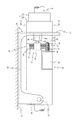
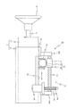
図1において、電動テレスコ調整式ステアリング装置16は、車両の前後方向に延長し、車両後方側にステアリングホイール8を固定したステアリングシャフト9を、車体に支持したコラム部材1の内側に回転自在に支持している。このステアリングシャフト9の車両前方側端部は、両端に自在継手17a、17bを有する中間シャフト18を介してステアリングギヤ19の入力軸に、操舵トルクを伝達可能に連結されている。   In FIG. 1, an electric telescopic adjustment type steering device 16 extends in the front-rear direction of the vehicle, and supports a steering shaft 9 having a steering wheel 8 fixed to the rear side of the vehicle, rotatably inside a column member 1 supported by the vehicle body. is doing. The vehicle front side end portion of the steering shaft 9 is connected to an input shaft of the steering gear 19 through an intermediate shaft 18 having universal joints 17a and 17b at both ends so that steering torque can be transmitted.

このステアリングギヤ19は図示しないが入力軸に連結されたピニオンとこのピニオンと噛合するラックを有するラック軸とを有するラックピニオン機構で構成され、ラック軸がタイロッド20を介して図示しない転舵輪に連結されている。
そして、ステアリングホイール8を操舵することにより、操舵トルクがステアリングギヤ19に伝達され、その出力軸となるラック軸からタイロッド20を介して図示しない転舵輪に伝達されることにより、ステアリングホイール8の回転方向に応じて転舵輪が転舵される。
Although not shown, the steering gear 19 includes a rack and pinion mechanism having a pinion connected to an input shaft and a rack shaft having a rack meshing with the pinion. The rack shaft is connected to a steered wheel (not shown) via a tie rod 20. Has been.
Then, by steering the steering wheel 8, steering torque is transmitted to the steering gear 19, and from the rack shaft serving as the output shaft to the steered wheel (not shown) via the tie rod 20, rotation of the steering wheel 8 is achieved. The steered wheels are steered according to the direction.

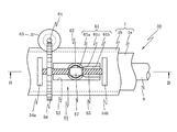
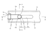
コラム部材1は、図2に示すように、ステアリングシャフト9を回転自在に支持したインナコラム1aとこのインナコラム1aが伸縮自在に内嵌されたアウタコラム1bとで構成されている。アウタコラム1bは、車体側部材21に固定した鋼板プレス成形品のコラムブラケット22に支持されている。このコラムブラケット22は、車体側部材21に固着される取付部23と、この取付部23の前端から下方に延設されたピボット部24と、取付部23の後端から下方に延設されたコラム支持用板部25とから構成されている。   As shown in FIG. 2, the column member 1 includes an inner column 1a that rotatably supports a steering shaft 9, and an outer column 1b in which the inner column 1a is telescopically fitted. The outer column 1b is supported by a column bracket 22 of a steel plate press-formed product fixed to the vehicle body side member 21. The column bracket 22 includes a mounting portion 23 that is fixed to the vehicle body side member 21, a pivot portion 24 that extends downward from the front end of the mounting portion 23, and a lower portion that extends downward from the rear end of the mounting portion 23. It is comprised from the column support plate part 25. FIG.

ここで、ピボット部24では、下端部にコラム部材1にその軸方向に直交する方向に突設されたピボットピン26を回転自在に支持しており、このピボットピン26を中心にしてコラム部材1が上下方向に揺動自在に支持されている。
一方、コラム支持用板部25は、図3に示すように、矩形板状に形成され、その左右方向の中央部に、コラム部材1を構成するアウタコラム1bの車両後端側端部(図2の右端部)を上下動可能に案内する上下方向に延長する長孔25aが形成されている。
Here, in the pivot portion 24, a pivot pin 26 projecting from the column member 1 in a direction perpendicular to the axial direction is rotatably supported at the lower end portion, and the column member 1 is centered on the pivot pin 26. Is supported so as to be swingable in the vertical direction.
On the other hand, the column support plate portion 25 is formed in a rectangular plate shape as shown in FIG. 3, and the vehicle rear end side end portion of the outer column 1b constituting the column member 1 (see FIG. 2 is formed with a long hole 25a extending in the up-down direction for guiding the right end portion 2) to be movable up and down.

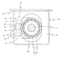
そして、コラム部材1のチルト調整を行うために電動チルト調整機構27が設けられている。この電動チルト調整機構27は、図2に示すように、コラム部材1に取付けられたボールねじ軸支持用ブラケット28と、このブラケット28に回転自在に支持されたボールねじ軸31と、このボールねじ軸31にボールを介して螺合するボールナット32と、ボールねじ軸31を回転駆動する電動モータ38とを備えている。   An electric tilt adjusting mechanism 27 is provided for adjusting the tilt of the column member 1. As shown in FIG. 2, the electric tilt adjusting mechanism 27 includes a ball screw shaft support bracket 28 attached to the column member 1, a ball screw shaft 31 rotatably supported by the bracket 28, and the ball screw. A ball nut 32 screwed to the shaft 31 via a ball and an electric motor 38 that rotationally drives the ball screw shaft 31 are provided.

ボールねじ軸支持用ブラケット28は、コラム部材1の外周面の幅方向片側(図2の表側、図3の左側)に、コラムブラケット22のコラム支持用板部25と略平行に一体に形成されている。このブラケット28には、その上下のアッパ支持部29とロア支持部30との間にボールねじ軸31が配置され、その上下両端部が図示しない転がり軸受により回転自在に支持されている。   The ball screw shaft support bracket 28 is integrally formed on one side in the width direction of the outer peripheral surface of the column member 1 (the front side in FIG. 2 and the left side in FIG. 3) substantially in parallel with the column support plate portion 25 of the column bracket 22. ing. The bracket 28 has a ball screw shaft 31 disposed between the upper and lower upper support portions 29 and the lower support portion 30, and both upper and lower end portions thereof are rotatably supported by rolling bearings (not shown).

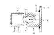
ボールねじ軸31には、図2及び図3に示すように、ボールナット32がボールを介在して螺合され、このボールナット32の車両後方側端面にボール部33と軸部34とからなるボールスタッド35の軸部34が固定されている。ボールスタッド35のボール部33はコラムブラケット22のコラム支持用板部25の車両後方側端面における例えばピボット軸26と同一高さ位置に突出形成された円筒状のスリーブ36内に係合されている。なお、回転運動を直線運動に変換する機構としては上述したボールねじを適用する場合に限らず、ねじ軸に直接ナットを螺合させるようにしてもよい。   As shown in FIGS. 2 and 3, a ball nut 32 is screwed onto the ball screw shaft 31 with a ball interposed therebetween, and a ball portion 33 and a shaft portion 34 are formed on an end surface of the ball nut 32 on the vehicle rear side. A shaft portion 34 of the ball stud 35 is fixed. The ball portion 33 of the ball stud 35 is engaged in a cylindrical sleeve 36 that is formed at the same height position as the pivot shaft 26 on the rear end surface of the column support plate portion 25 of the column bracket 22, for example. . The mechanism for converting the rotational motion into the linear motion is not limited to the case where the above-described ball screw is applied, and a nut may be directly screwed onto the screw shaft.

また、ボールねじ軸支持用ブラケット28には、図2に示すように、電動モータ38の例えば断面矩形のケース体39がその回転軸をコラム部材1の軸方向と平行となるように固定されている。
この電動モータ38は、例えばブラシ付き直流モータ、ブラシレスモータ等で構成され、図2に示すように、回転軸40にウォーム41が連結され、このウォーム41が前述したボールねじ軸31の下端側に取付けられたウォームホイール42に噛合されている。
As shown in FIG. 2, for example, a case body 39 having a rectangular cross section of the electric motor 38 is fixed to the ball screw shaft support bracket 28 so that the rotation shaft thereof is parallel to the axial direction of the column member 1. Yes.
The electric motor 38 is composed of, for example, a brushed DC motor, a brushless motor, or the like. As shown in FIG. 2, a worm 41 is connected to the rotary shaft 40, and the worm 41 is connected to the lower end side of the ball screw shaft 31 described above. It is meshed with the attached worm wheel 42.

したがって、電動モータ38を正逆転駆動することにより、ウォーム41及びウォームホイール42を介してボールねじ軸31が正逆転されることにより、ボールナット32に取付けたボールスタッド35がコラムブラケット22のコラム支持用板部25に固定されたスリーブ36に係合されているので、コラム部材1がピボット軸26を中心として上下に回動してチルト調整を行うことができる。   Therefore, when the electric motor 38 is driven forward / reversely, the ball screw shaft 31 is rotated forward / reversely via the worm 41 and the worm wheel 42, so that the ball stud 35 attached to the ball nut 32 supports the column of the column bracket 22. Since the column member 1 is engaged with the sleeve 36 fixed to the plate portion 25, the column member 1 can be rotated up and down around the pivot shaft 26 to perform tilt adjustment.

このコラム部材1のチルト調整時に、コラム部材1がピボット軸26を中心として回動するため、ボールナット32のボールスタッド35を取付けた面が、図4で拡大図示したように、ピポット軸26を中心とする円弧上の各点の接線方向に延長することになるので、ボールナット32が実線図示の中立位置に対して上下方向に移動することにより、上下端位置で二点鎖線図示のように傾斜すると共にスリーブ36に対する距離が変化することになるが、ボールスタッド35のボール部33が円筒状のスリーブ36に係合しているので、ボールナット32の傾斜及び距離変化を許容することができ、チルト調整を阻害したり、各構成部材に不要な応力や摩擦を生じさせたりすることを防止することができる。   When the column member 1 is tilt-adjusted, the column member 1 rotates about the pivot shaft 26. Therefore, the surface of the ball nut 32 to which the ball stud 35 is attached is connected to the pivot shaft 26 as shown in FIG. Since it extends in the tangential direction of each point on the center arc, when the ball nut 32 moves in the vertical direction with respect to the neutral position shown in the solid line, as shown in the two-dot chain line at the upper and lower end positions. The distance to the sleeve 36 changes with the inclination, but since the ball portion 33 of the ball stud 35 is engaged with the cylindrical sleeve 36, the inclination of the ball nut 32 and a change in the distance can be allowed. In addition, it is possible to prevent the tilt adjustment from being hindered and the occurrence of unnecessary stress and friction on each component member.

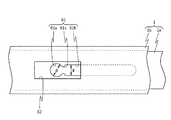
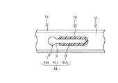
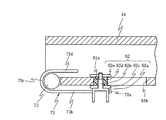
また、コラム部材1には、図5に示すように、電動テレスコ調整機構50が設けられている。この電動テレスコ調整機構50は、インナコラム1aをアウタコラム1bに対して伸縮させる電動アクチュエータ51を備えている。
この電動アクチュエータ51を装着するアウタコラム1bの下端には、図5及び図6に示すように、軸方向に延長してインナコラム1aを露出させる開口部52が形成され、また、インナコラム1aの開口部52に対向する下端外周面が、図9に示すように、平坦面53とされている。
Further, the column member 1 is provided with an electric telescopic adjustment mechanism 50 as shown in FIG. The electric telescopic adjustment mechanism 50 includes an electric actuator 51 that expands and contracts the inner column 1a with respect to the outer column 1b.
As shown in FIGS. 5 and 6, an opening 52 that extends in the axial direction to expose the inner column 1a is formed at the lower end of the outer column 1b to which the electric actuator 51 is mounted. The outer peripheral surface at the lower end facing the opening 52 is a flat surface 53 as shown in FIG.

そして、電動アクチュエータ51は、アウタコラム1bの開口部52の軸方向両端位置に一体に突出形成されたボールねじ軸保持板部54a及び54bを有し、これらボールねじ軸保持板部54a及び54b間に図示しない転がり軸受で回転自在に保持されたボールねじ軸55が回転自在に配設されている。このボールねじ軸55には前述した電動チルト調整機構27と同様に車両前方側(図8で左端側)にウォームホイール56が一体に取付けられている。   The electric actuator 51 has ball screw shaft holding plate portions 54a and 54b that are integrally formed at both axial end positions of the opening 52 of the outer column 1b, and between these ball screw shaft holding plate portions 54a and 54b. Further, a ball screw shaft 55 rotatably held by a rolling bearing (not shown) is rotatably arranged. As with the electric tilt adjusting mechanism 27 described above, a worm wheel 56 is integrally attached to the ball screw shaft 55 on the front side of the vehicle (left end side in FIG. 8).

また、ボールねじ軸55にボールを介して出力部としてのボールナット57が螺合され、このボールナット57にボール部58と軸部59とを有するボールスタッド60が固定され、そのボール部58がインナコラム1aの開口部52から露出する外周面に軸方向に延長して形成された長孔61内に係合された円筒状のスリーブ62に係合されている。この場合も、前述した電動チルト調整機構27と同様にボールねじに変えてねじ軸とこれに螺合するナットを適用することができる。
一方、車両前方側のボールねじ軸保持板部54aには電動モータ63が取付けられ、その回転軸に形成されたウォーム64(回転軸と一体であっても別体であってもよい)がボールねじ軸55に取付けられたウォームホイール56に噛合されている。
A ball nut 57 as an output portion is screwed onto the ball screw shaft 55 via a ball, and a ball stud 60 having a ball portion 58 and a shaft portion 59 is fixed to the ball nut 57, and the ball portion 58 is It is engaged with a cylindrical sleeve 62 that is engaged in a long hole 61 that is formed by extending in the axial direction on the outer peripheral surface exposed from the opening 52 of the inner column 1a. Also in this case, a screw shaft and a nut screwed to the screw shaft can be applied instead of the ball screw in the same manner as the electric tilt adjusting mechanism 27 described above.
On the other hand, an electric motor 63 is attached to the ball screw shaft holding plate portion 54a on the front side of the vehicle, and a worm 64 (which may be integrated with the rotating shaft or separate) may be formed on the rotating shaft. It is meshed with a worm wheel 56 attached to the screw shaft 55.

ここで、インナコラム1aに形成された長孔61は、図6〜図9に示すように、通常時にスリーブ62が係合する円形の通常時係合部61aと、この通常時係合部61aからステアリングホイール8側に延長し、インナコラム1aに衝撃荷重が入力されたときにスリーブ62が係合する長円形の衝撃荷重入力時係合部61bとを有し、通常時係合部61aと衝撃荷重入力時係合部61bとの間に対向側壁から夫々内方に突出し、且つ設定されたコラプス荷重以上の衝撃荷重の入力時にスリーブ62によって潰されるか又はスリーブ62が後述する円筒状スペーサ62dが収縮して乗り越えことが可能な突出部61cが形成されている。そして、通常時係合部61aの直径φに対して衝撃荷重入力時係合部61bの幅Wが狭く(φ>W)設定されて抵抗付与部とされ、スリーブ62が衝撃荷重入力時係合部61bを摺動する際に摩擦抵抗を発生させて衝撃エネルギを安定して吸収できるように設定されている。   Here, as shown in FIGS. 6 to 9, the long hole 61 formed in the inner column 1a includes a circular normal engagement portion 61a with which the sleeve 62 is normally engaged, and the normal engagement portion 61a. And an oval impact load input engagement portion 61b that engages with the sleeve 62 when an impact load is input to the inner column 1a. The normal engagement portion 61a When the impact load is input, the projecting portion protrudes inward from the opposite side wall between the engagement portion 61b and is collapsed by the sleeve 62 when an impact load greater than the set collapse load is input, or the sleeve 62 is a cylindrical spacer 62d described later. A protrusion 61c is formed that can contract and get over. Then, the width W of the engagement portion 61b at the time of impact load input is set narrow (φ> W) with respect to the diameter φ of the engagement portion 61a at the normal time to be a resistance applying portion, and the sleeve 62 is engaged at the time of impact load input. It is set so that the frictional energy is generated when the portion 61b is slid to absorb the impact energy stably.

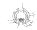
一方、スリーブ62は、図8及び図9に示すように、ボールスタッド60のボール部58が係合する下面を開放した有底円筒部62aと、この有底円筒部62aの上端面中央部から上方に突出し上端側に雄ねじを形成した支持軸62bと、この支持軸62bに外嵌されたアウタコラム1bの長孔61の幅より広い直径の間座62cと、この間座62c上に同様に支持軸62bに外嵌され且つインナコラム1aの厚みより僅かに厚い厚みで長孔61に係合する合成樹脂製の円筒状スペーサ62dと、支持軸62bの雄ねじに螺合するインナコラム1aの長孔61の通常時係合部61aより大きな直径のナット62eとで構成されている。ここで、間座62c及びナット62eの少なくともインナコラム1aの外周面及び内周面に接触する角部にはR面取りが施されている。   On the other hand, as shown in FIGS. 8 and 9, the sleeve 62 includes a bottomed cylindrical portion 62 a having an open lower surface with which the ball portion 58 of the ball stud 60 is engaged, and a center portion of the upper end surface of the bottomed cylindrical portion 62 a. A support shaft 62b protruding upward and having a male screw formed on the upper end side, a spacer 62c having a diameter wider than the width of the long hole 61 of the outer column 1b fitted on the support shaft 62b, and similarly supported on the spacer 62c. A cylindrical spacer 62d made of synthetic resin that is fitted on the shaft 62b and is slightly thicker than the inner column 1a and engages with the long hole 61, and a long hole in the inner column 1a that is screwed into the male screw of the support shaft 62b. 61, and a nut 62e having a diameter larger than that of the normal engagement portion 61a. Here, corner portions of the spacer 62c and the nut 62e that contact at least the outer peripheral surface and the inner peripheral surface of the inner column 1a are rounded.

そして、スリーブ62の支持軸62bに、先ず、間座62cを外嵌させ、その上から円筒状スペーサ62dを外嵌させた状態で、インナコラム1aの長孔61の通常時係合部61aに下側から挿通し、例えばインナコラム1a及びアウタコラム1bの通常時係合部61aに上方から対向する位置に穿設されたナット挿通孔65を通じてナット62eを挿入して支持軸62bの雄ねじに螺合させることにより、スリーブ62を通常時係合部61aに装着する。   Then, the spacer 62c is first fitted on the support shaft 62b of the sleeve 62, and the cylindrical spacer 62d is fitted on the spacer 62c. Then, the normal engagement portion 61a of the elongated hole 61 of the inner column 1a is fitted. The nut 62e is inserted through the nut insertion hole 65 formed at a position opposed to the normal engagement portion 61a of the inner column 1a and the outer column 1b from above, and is screwed into the male screw of the support shaft 62b. As a result, the sleeve 62 is attached to the normal engagement portion 61a.

次に、上記第1の実施形態の動作を説明する。
例えば運転者が運転席に着座して、コラム部材1のチルト角を調整したい場合には、例えばコラム部材1の脇に配置したコラム部材1のアップ/ダウンを指示するチルト調整用スイッチ(図示せず)を操作することにより、電動チルト調整機構27の電動モータ38を正逆転駆動してチルト角を調整することができる。
すなわち、チルト調整用スイッチでチルトアップを選択すると、図示しないモータ制御装置によって電動チルト調整機構27の電動モータ38が例えば逆転駆動され、これによってウォーム41及びウォームホイール42を介してボールねじ軸31が逆転されることにより、ボールナット32がボールねじ軸支持用ブラケット28のロア支持部30側に向かって移動することになる。
Next, the operation of the first embodiment will be described.
For example, when the driver is seated in the driver's seat and wants to adjust the tilt angle of the column member 1, for example, a tilt adjustment switch (not shown) that instructs up / down of the column member 1 disposed beside the column member 1. The tilt angle can be adjusted by driving the electric motor 38 of the electric tilt adjusting mechanism 27 forward and backward.
That is, when tilt up is selected with the tilt adjustment switch, the electric motor 38 of the electric tilt adjustment mechanism 27 is driven in reverse, for example, by a motor control device (not shown), whereby the ball screw shaft 31 is moved via the worm 41 and the worm wheel 42. By being reversed, the ball nut 32 moves toward the lower support portion 30 side of the ball screw shaft support bracket 28.

しかしながら、ボールナット32はこれに固定されたボールスタッド35のボール部33が車体側部材21に固定されたコラムブラケット22のコラム支持用板部25に固定された円筒状のスリーブ36内に係合しているので、ボールナット32は上下方向に移動することはなく、逆にボールねじ軸31が上方に移動することになり、ボールねじ軸支持用ブラケット28を介してコラム部材1がピボット部24のピボットピン26を支点としてコラム支持用板部25の長孔25aに案内されてチルトアップすることになる。
そして、コラム部材1が所望のチルトアップ位置となったときにチルト調整用スイッチをオフ状態に復帰させることにより、電動モータ38の逆転駆動が停止されてコラム部材1が所望のチルトアップ位置を保持する。
However, the ball nut 32 is engaged with the cylindrical sleeve 36 fixed to the column support plate portion 25 of the column bracket 22 fixed to the vehicle body side member 21 with the ball portion 33 of the ball stud 35 fixed thereto. Therefore, the ball nut 32 does not move up and down, but the ball screw shaft 31 moves upside down, and the column member 1 is pivoted through the ball screw shaft support bracket 28. With the pivot pin 26 as a fulcrum, it is guided to the long hole 25a of the column support plate portion 25 and tilted up.
When the column member 1 reaches the desired tilt up position, the tilt adjustment switch is returned to the OFF state, whereby the reverse rotation of the electric motor 38 is stopped and the column member 1 maintains the desired tilt up position. To do.

同様に、コラム部材1をチルトダウンさせる場合には、チルト調整用スイッチ(図示せず)でチルトダウンを選択して、図示しないモータ制御装置で電動モータ38を正転駆動することにより、ウォーム41及びウォームホイール42を介してボールねじ軸31が正転駆動される。このため、コラム部材1がコラムブラケット22のコラム支持用板部25の長孔25aによって案内されてピボット部24のピボットピン26を支点としてチルトダウンする。そして、コラム部材1が所望のチルトダウン位置に達したときにチルト調整用スイッチをオフ状態とすることにより、電動モータ38の駆動が停止されて所望のチルトダウン位置を保持する。   Similarly, when the column member 1 is tilted down, tilt down is selected by a tilt adjustment switch (not shown), and the electric motor 38 is driven to rotate forward by a motor control device (not shown) to thereby drive the worm 41. The ball screw shaft 31 is driven to rotate forward via the worm wheel 42. Therefore, the column member 1 is guided by the long hole 25a of the column support plate portion 25 of the column bracket 22 and tilted down with the pivot pin 26 of the pivot portion 24 as a fulcrum. When the column member 1 reaches the desired tilt-down position, the tilt adjustment switch is turned off to stop the drive of the electric motor 38 and maintain the desired tilt-down position.

このように、電動モータ38を正逆転駆動することにより、コラム部材1がピボットピン26を中心として上下方向に揺動してチルト位置を調整することができるものであるが、このコラム部材1の上下方向の揺動に応じてボールナット32に固定されているボールスタッド35のスリーブ36に対する軸方向位置及び角度が変化することになる。
しかしながら、ボールスタッド35のボール部33がスリーブ36に係合しているので、ボールスタッド35の軸方向位置や角度が変化してもボール部33が軸方向に摺動したり摺接点が円周方向に移動したりすることにより、ボール部33とスリーブ36との係合関係が崩れることはなく、チルト動作を円滑に行うことができる。
Thus, by driving the electric motor 38 forward and backward, the column member 1 can swing up and down about the pivot pin 26 to adjust the tilt position. The axial position and angle of the ball stud 35 fixed to the ball nut 32 with respect to the sleeve 36 change in accordance with the vertical swing.
However, since the ball portion 33 of the ball stud 35 is engaged with the sleeve 36, even if the axial position and angle of the ball stud 35 change, the ball portion 33 slides in the axial direction and the sliding contact is circumferential. By moving in the direction, the engagement relationship between the ball portion 33 and the sleeve 36 is not lost, and the tilting operation can be performed smoothly.

また、コラム部材1のアウタコラム1bに対してインナコラム1aを伸縮させるテレスコ位置調整を行いたい場合には、例えばコラム部材1の脇に配置したテレスコ位置の伸張/収縮を指示するテレスコ調整用スイッチ(図示せず)を操作することにより、電動テレスコ調整機構50の電動モータ63を正逆転駆動してテレスコ位置を調整することができる。
すなわち、テレスコ位置調整スイッチで伸張を選択すると、図示しないモータ制御装置によって電動テレスコ調整機構50の電動モータ63が例えば逆転駆動され、これによってウォーム64及びウォームホイール56を介してボールねじ軸55が逆転されることにより、ボールナット57がボールねじ軸保持板部54b側に向かって移動することになる。
Further, when telescopic position adjustment for expanding / contracting the inner column 1a with respect to the outer column 1b of the column member 1 is desired, for example, a telescopic adjustment switch for instructing expansion / contraction of the telescopic position disposed on the side of the column member 1 By operating (not shown), the electric motor 63 of the electric telescopic adjustment mechanism 50 can be driven forward and backward to adjust the telescopic position.
That is, when extension is selected by the telescopic position adjustment switch, the electric motor 63 of the electric telescopic adjustment mechanism 50 is driven in reverse by a motor control device (not shown), whereby the ball screw shaft 55 is rotated in reverse via the worm 64 and the worm wheel 56. As a result, the ball nut 57 moves toward the ball screw shaft holding plate portion 54b.

このとき、ボールナット57に取付けたボールスタッド60のボール部58がスリーブ62の有底円筒部62a内に係合し、このスリーブ62がインナコラム1aに形成した長孔61の通常時係合部61aに係合しており、通常時係合部61aと衝撃荷重入力時係合部61bとの間に通常時には通過できない突出部61cが形成されているので、通常時にスリーブ62が突出部61cを越えて衝撃荷重入力時係合部61bに係合することが阻止されている。このボールナット57のステアリングホイール8側への移動に伴って、インナコラム1aがアウタコラム1bに対して伸張する。そして、インナコラム1aが所望のテレスコ伸張位置となったときにテレスコ調整用スイッチをオフ状態に復帰させることにより、電動モータ63の逆転駆動が停止されてインナコラム1aが所望のテレスコ伸張位置を保持する。   At this time, the ball portion 58 of the ball stud 60 attached to the ball nut 57 is engaged with the bottomed cylindrical portion 62a of the sleeve 62, and the sleeve 62 is normally engaged with the long hole 61 formed in the inner column 1a. Since the projecting portion 61c is engaged between the normal-time engaging portion 61a and the impact-load-input engaging portion 61b and cannot be normally passed, the sleeve 62 moves the projecting portion 61c in the normal time. Being engaged with the engaging portion 61b at the time of impact load input is prevented. As the ball nut 57 moves toward the steering wheel 8, the inner column 1a extends relative to the outer column 1b. When the inner column 1a reaches the desired telescopic extension position, the telescopic adjustment switch is returned to the OFF state, so that the reverse rotation of the electric motor 63 is stopped and the inner column 1a maintains the desired telescopic extension position. To do.

同様に、コラム部材1のインナコラム1aをアウタコラム1bに対して収縮させるには、テレスコ調整用スイッチ(図示せず)でテレスコ収縮を選択して、図示しないモータ制御装置で電動モータ63を正転駆動することにより、ウォーム64及びウォームホイール56を介してボールねじ軸55が正転駆動される。このため、ボールナット57がボールねじ軸保持板部54a側に移動され、これに応じてインナコラム1aがアウタコラム1bに対して収縮する。そして、インナコラム1aが所望のテレスコ収縮位置となったときにテレスコ調整用スイッチをオフ状態に復帰させることにより、電動モータ63の正転駆動が停止されてインナコラム1aが所望のテレスコ収縮位置を保持する。   Similarly, in order to contract the inner column 1a of the column member 1 with respect to the outer column 1b, telescopic contraction is selected by a telescopic adjustment switch (not shown), and the electric motor 63 is adjusted by a motor control device (not shown). By rolling and driving, the ball screw shaft 55 is driven to rotate forward via the worm 64 and the worm wheel 56. For this reason, the ball nut 57 is moved to the ball screw shaft holding plate portion 54a side, and the inner column 1a is contracted with respect to the outer column 1b accordingly. Then, when the inner column 1a reaches the desired telescopic contraction position, the telescopic adjustment switch is returned to the OFF state, whereby the forward drive of the electric motor 63 is stopped and the inner column 1a is set to the desired telescopic contraction position. Hold.

このように、電動テレスコ調整機構50でテレスコ位置調整を行う場合には、ボールナット57に取付けられたボールスタッド60のボール部58が係合しているスリーブ62が、インナコラム1aに形成された長孔61の通常時係合部61aに係合しており、衝撃荷重入力時係合部61bとの間に突出部61cが形成されているので、通常のテレスコ位置調整ではスリーブ62の円筒状スペーサ62dが突出部61cを通過することはなく、ボールナット57の移動に伴ってインナコラム1aが伸縮される。   Thus, when the telescopic position adjustment is performed by the electric telescopic adjustment mechanism 50, the sleeve 62 with which the ball portion 58 of the ball stud 60 attached to the ball nut 57 is engaged is formed in the inner column 1a. Since the protrusion 61c is formed between the elongated hole 61 and the normal engagement portion 61a of the long hole 61 and the engagement portion 61b when the impact load is input, the cylindrical shape of the sleeve 62 is used for normal telescopic position adjustment. The spacer 62d does not pass through the protrusion 61c, and the inner column 1a is expanded and contracted as the ball nut 57 moves.

ところが、二次衝突時に、ステアリングホイール8に車両前方への設定されたコラプス荷重以上の衝撃荷重が作用すると、この衝撃荷重がステアリングホイール8からステアリングシャフト9を介してこのステアリングシャフト9を回転自在に支持するインナコラム1aに伝達される。
このときのインナコラム1aに伝達される衝撃荷重がコラプス荷重以上であり、スリーブ62がその有底円筒部62aにボールナット57に形成されたボールスタッド60のボール部58が係合して、軸方向の移動が規制されているので、インナコラム1aに伝達される衝撃荷重によってインナコラム1aに形成された長孔61における通常時係合部61a及び衝撃荷重入力時係合部61b間の突出部61cがスリーブ62の円筒状スペーサ62dによって潰されるか又は円筒状スペーサ62dが変形することにより、長孔61の通常時係合部61aが円筒状スペーサ62dに係合している状態から突出部61cを通過して衝撃荷重入力時係合部61bが円筒状スペーサ62dに係合する状態に移行する。
However, if an impact load greater than the collapse load set in front of the vehicle acts on the steering wheel 8 during the secondary collision, the impact load can rotate the steering shaft 9 from the steering wheel 8 via the steering shaft 9. It is transmitted to the supporting inner column 1a.
The impact load transmitted to the inner column 1a at this time is equal to or greater than the collapse load, and the ball portion 58 of the ball stud 60 formed on the ball nut 57 is engaged with the bottomed cylindrical portion 62a of the sleeve 62, so that the shaft Since the movement in the direction is restricted, the protrusion between the normal engagement portion 61a and the impact load input engagement portion 61b in the long hole 61 formed in the inner column 1a by the impact load transmitted to the inner column 1a. 61c is crushed by the cylindrical spacer 62d of the sleeve 62 or the cylindrical spacer 62d is deformed, so that the normal-time engaging portion 61a of the long hole 61 is engaged with the cylindrical spacer 62d from the protruding portion 61c. Then, the state shifts to the state where the engaging portion 61b engages with the cylindrical spacer 62d when the impact load is input.

このため、インナコラム1aがアウタコラム1b内に収縮し、このインナコラム1aの収縮時に、衝撃荷重入力時係合部61bの幅Wが通常時係合部61aの直径より狭められていることから、スリーブ62の円筒状スペーサ62dとの間に適度な摩擦抵抗が生じ、これによりステアリングホイール8に伝達された衝撃荷重の衝撃エネルギを安定して吸収することができる。   For this reason, the inner column 1a contracts into the outer column 1b, and when the inner column 1a contracts, the width W of the engaging portion 61b at the time of impact load input is narrower than the diameter of the engaging portion 61a at the normal time. An appropriate frictional resistance is generated between the sleeve 62 and the cylindrical spacer 62d, so that the impact energy of the impact load transmitted to the steering wheel 8 can be stably absorbed.

このように、上記実施形態によると、テレスコ位置の位置決めを行うボールナット57に取付けられたボールスタッド60のボール部58がスリーブ62の有底円筒部62aに係合し、このスリーブ62の円筒状スペーサ62dが通常時はインナコラム1aに形成された長孔61の通常時係合部61aに係合しているが、インナコラム1aにコラプス荷重以上の衝撃荷重が伝達されたときに、長孔61の突出部61cがスリーブ62の円筒状スペーサ62dを通過して衝撃荷重入力時係合部61bがスリーブ62の円筒状スペーサ62dに係合する状態となり、この状態で円筒状スペーサ62dと衝撃荷重入力時係合部61bとの間に摩擦抵抗が発生して、衝撃荷重の衝撃エネルギを確実に吸収することができる。
しかも、インナコラム1aに形成した長孔61とこれに係合するボールナット57に結合されたスリーブ62とを設けるだけの簡単な構成で、衝撃エネルギを吸収することができ、ステアリング装置全体を離脱させる必要がないので、ステアリング装置のレイアウトの自由度を向上させることができる。
Thus, according to the above-described embodiment, the ball portion 58 of the ball stud 60 attached to the ball nut 57 for positioning the telescopic position engages with the bottomed cylindrical portion 62a of the sleeve 62, and the cylindrical shape of the sleeve 62 is obtained. The spacer 62d is normally engaged with the normal engagement portion 61a of the long hole 61 formed in the inner column 1a. When an impact load greater than the collapse load is transmitted to the inner column 1a, the long hole The protruding portion 61c of 61 passes through the cylindrical spacer 62d of the sleeve 62, and the engaging portion 61b engages with the cylindrical spacer 62d of the sleeve 62 when an impact load is input. In this state, the cylindrical spacer 62d and the impact load are engaged. A frictional resistance is generated between the input engaging portion 61b and the impact energy of the impact load can be reliably absorbed.
Moreover, the impact energy can be absorbed and the entire steering apparatus can be separated by simply providing a long hole 61 formed in the inner column 1a and a sleeve 62 coupled to the ball nut 57 engaged therewith. Therefore, the degree of freedom in the layout of the steering device can be improved.

なお、上記実施形態においては、インナコラム1aに形成した長孔61の衝撃荷重入力時係合部61bがその幅Wが通常時係合部61aの直径φより小さく設定されてスリーブ62の円筒状スペーサ62dとの間に摩擦抵抗を与えるように構成した場合について説明したが、これに限定されるものではなく、長孔の変形例を表す図10に示すように、衝撃荷重入力時係合部61bのスリーブ62の円筒状スペーサ62dが摺接する摺接面に抵抗付与部としての合成樹脂材70を配設してスリーブ62の円筒状スペーサ62dとの間に摩擦抵抗を発生させるように構成してもよい。   In the above embodiment, the engagement portion 61b of the elongated hole 61 formed in the inner column 1a is set to have a width W smaller than the diameter φ of the normal engagement portion 61a so that the sleeve 62 has a cylindrical shape. The case where the frictional resistance is provided between the spacer 62d and the spacer 62d has been described. However, the present invention is not limited to this, and as shown in FIG. A synthetic resin material 70 is provided as a resistance imparting portion on the sliding contact surface with which the cylindrical spacer 62d of the sleeve 62b is in sliding contact, and a frictional resistance is generated between the sleeve 62 and the cylindrical spacer 62d. May be.

また、長孔の変形例を表す図11に示すように、インナコラム1aに形成した長孔61の衝撃荷重入力時係合部61bを、突出部61cと同様の突出部71を軸方向に所定間隔を保って複数配列して抵抗付与部を形成し、衝撃荷重が入力されたときに突出部71とスリーブ62の円筒状スペーサ62dとの間で摩擦抵抗を発生させるようにしてもよい。   Further, as shown in FIG. 11 showing a modified example of the long hole, the engagement portion 61b of the long hole 61 formed in the inner column 1a is set in the axial direction with the protruding portion 71 similar to the protruding portion 61c being set in the axial direction. A plurality of resistance imparting portions may be formed by arranging them at intervals, and a frictional resistance may be generated between the protruding portion 71 and the cylindrical spacer 62d of the sleeve 62 when an impact load is input.

さらに、長孔の変形例を表す図12〜図14に示すように、衝撃荷重入力時係合部61bの幅Wを通常時係合部61aの直径以上の幅に形成し、これに応じて、インナコラム1aの長孔61の延長線上におけるステアリングホイール8とは反対側の端部にローラ72をその軸方向をインナコラム1aの軸方向と直交する方向として回転自在に支持すると共に、スリーブ62の有底円筒部62aにおけるステアリングホイール8側の外周面を半周するU字状部73aと、このU字状部73aの両端からローラ72に達する平行直線部73bと、この平行直線部73bの端部でローラ72に沿って180°折り曲げられた折り曲げ部73cと、この折り曲げ部73cからインナコラム1aの内周面に沿って延長する延長部73dとで構成されるワイヤ73を配設するようにしてもよい。この場合には、インナコラム1aにコラプス荷重以上の衝撃荷重が入力されたときに、インナコラム1aの長孔61における突出部61cがスリーブ62の円筒状スペーサ62dを通過して衝撃荷重入力時係合部61bがスリーブ62の円筒状スペーサ62dと係合する状態となってインナコラム1aがアウタコラム1b内に収縮する際に、インナコラム1aの収縮に伴ってワイヤ73の折り曲げ部73cがローラ72位置でしごかれることにより摩擦抵抗を発生させて、衝撃荷重の衝撃エネルギを吸収するように構成してもよい。なお、ワイヤ73に代えてワイヤ73と同一形状に形成した薄板状のプレートを適用するようにしてもよい。また、ワイヤ73の断面形状は丸型の針金状のものに限られず、断面が長円形や多角形のものでもよく、また断面が長方形のプレートを適用するようにしてもよい。   Further, as shown in FIG. 12 to FIG. 14 showing modifications of the long holes, the width W of the engaging portion 61b at the time of impact load input is formed to be equal to or larger than the diameter of the normal engaging portion 61a. The roller 72 is rotatably supported at the end opposite to the steering wheel 8 on the extended line of the long hole 61 of the inner column 1a with its axial direction orthogonal to the axial direction of the inner column 1a. A U-shaped portion 73a half-circulating the outer peripheral surface on the steering wheel 8 side of the bottomed cylindrical portion 62a, a parallel straight portion 73b reaching the roller 72 from both ends of the U-shaped portion 73a, and an end of the parallel straight portion 73b A bent portion 73c that is bent by 180 ° along the roller 72 and an extension portion 73d that extends from the bent portion 73c along the inner peripheral surface of the inner column 1a. Ya 73 may be disposed. In this case, when an impact load equal to or greater than the collapse load is input to the inner column 1a, the protrusion 61c in the long hole 61 of the inner column 1a passes through the cylindrical spacer 62d of the sleeve 62, and the impact load is input. When the inner column 1a contracts into the outer column 1b with the joining portion 61b engaging with the cylindrical spacer 62d of the sleeve 62, the bent portion 73c of the wire 73 is moved to the roller 72 as the inner column 1a contracts. A frictional resistance may be generated by squeezing at a position to absorb the impact energy of the impact load. Instead of the wire 73, a thin plate formed in the same shape as the wire 73 may be applied. The cross-sectional shape of the wire 73 is not limited to a round wire shape, and a cross-sectional shape may be an oval or polygonal shape, or a plate having a rectangular cross-section may be applied.

さらにまた、上記実施形態においては、電動アクチュエータ51を構成するボールねじ軸55、電動モータ63等をアウタコラム1bに固定し、電動アクチュエータ51の出力部となるボールナット57に取付けたボールスタッド60のボール部58が係合するスリーブ62をインナコラム1aとの結合部に設けた長孔61に係合させる場合について説明したが、これに限定されるものではなく、インナコラム1aに電動アクチュエータ51を構成するボールねじ55及び電動モータ63を固定し、ボールナット57に取付けられたボールスタッド60のボール部58が係合するスリーブ62をアウタコラム1bに形成した通常時係合部61a、衝撃荷重入力時係合部61b及び突出部61cを有する長孔61に係合させるようにしてもよい。   Furthermore, in the above-described embodiment, the ball screw shaft 55, the electric motor 63, and the like constituting the electric actuator 51 are fixed to the outer column 1b, and the ball stud 60 attached to the ball nut 57 serving as the output portion of the electric actuator 51 is used. Although the case where the sleeve 62 with which the ball portion 58 engages is engaged with the long hole 61 provided in the coupling portion with the inner column 1a has been described, the present invention is not limited to this, and the electric actuator 51 is attached to the inner column 1a. A normal engagement portion 61a in which a ball screw 55 and an electric motor 63 are fixed, and a sleeve 62 that engages a ball portion 58 of a ball stud 60 attached to a ball nut 57 is formed in the outer column 1b. You may make it engage with the long hole 61 which has the hour engaging part 61b and the protrusion part 61c.

なおさらに、上記実施形態においては、スリーブ62をインナコラム1aに形成した長孔61に係合させる場合について説明したが、これに限定されるものではなく、スリーブ62をインナコラム1aに固定し、ボールナット57に通常時係合部61a、衝撃荷重入力時係合部61b及び突出部61cを有する長孔61に対応する長孔を設け、この長孔にボールスタッド60の軸部59を前述したスリーブ62と同様の構成で係合させるようにしてもよい。   Furthermore, in the above-described embodiment, the case where the sleeve 62 is engaged with the long hole 61 formed in the inner column 1a has been described. However, the present invention is not limited to this, and the sleeve 62 is fixed to the inner column 1a. The ball nut 57 is provided with a long hole corresponding to the long hole 61 having the normal engagement portion 61a, the impact load input engagement portion 61b, and the protruding portion 61c, and the shaft portion 59 of the ball stud 60 is described above in the long hole. You may make it engage by the structure similar to the sleeve 62. FIG.

また、上記実施形態においては、ボールナット57をボールスタッド60及びスリーブ62を介してインナコラム1aの長孔61に係合させる場合について説明したが、これに限定されるものではなく、スタッド60及びスリーブ62を省略し、これらに代えてボールナット57に直接インナコラム1aの長孔61に係合する係合片を形成するようにしてもよい。この場合も、インナコラム1aに係合片を固定し、ボールナット57に長孔61を形成するようにしてもよい。さらには、インナコラム1aの長孔61を省略して、スリーブ62を直接インナコラム1aに取付け、二次衝突時の衝撃荷重が作用したときに、ボールスタッド60のボール部58とボールナット57との間が破断するように構成してもよい。   In the above embodiment, the case where the ball nut 57 is engaged with the elongated hole 61 of the inner column 1a via the ball stud 60 and the sleeve 62 has been described. However, the present invention is not limited to this. The sleeve 62 may be omitted, and instead of these, an engagement piece that directly engages with the elongated hole 61 of the inner column 1a may be formed on the ball nut 57. Also in this case, the engagement piece may be fixed to the inner column 1 a and the elongated hole 61 may be formed in the ball nut 57. Furthermore, the long hole 61 of the inner column 1a is omitted, the sleeve 62 is directly attached to the inner column 1a, and when the impact load at the time of the secondary collision is applied, the ball portion 58 of the ball stud 60 and the ball nut 57 You may comprise so that between may be fractured.

さらに、上記実施形態においては、インナコラム1aに形成した長孔61の突出部61cを対向側壁の夫々から内方に突出させた場合について説明したが、これに限定されるものではなく、対向側壁の何れか一方のみから突出させるようにしてもよい。
さらにまた、上記実施形態においては、電動テレスコ調整式ステアリング装置16が電動チルト調整機構27を有する場合について説明したが、これに限定されるものではなく、電動チルト調整機構27を省略することもできる。
Furthermore, in the above-described embodiment, the case where the protruding portion 61c of the long hole 61 formed in the inner column 1a is protruded inward from each of the opposing side walls is not limited to this. You may make it protrude only from any one of these.
Furthermore, in the above embodiment, the case where the electric telescopic adjustment type steering device 16 has the electric tilt adjustment mechanism 27 has been described. However, the present invention is not limited to this, and the electric tilt adjustment mechanism 27 can be omitted. .

なおさらに、上記実施形態においては、電動テレスコ機構50について二次衝突時の衝撃荷重が入力されたときに電動アクチュエータの出力部とインナコラム及びアウタコラムの他方との結合部を相対移動可能に構成した場合について説明したが、これに限定されるものではなく、電動チルト機構30についてもコラムブラケット22に通常時係合部61a及びその上側に連接する衝撃荷重入力時係合部61bを有する長孔61を形成して、その通常時係合部61aにスリーブ36を係合させることにより、ステアリングホイール8に二次衝突時の衝撃荷重が作用したときにその垂直分力によってステアリングコラム1が上方に移動されるときに、スリーブ36が通常時係合部61aから脱して衝撃荷重入力時係合部61bを摺動することにより、摩擦抵抗を発生させて衝撃エネルギを安定して吸収することができる。この場合も電動テレスコ機構50と同様に図10〜図14に示す変形例も適用することができる。さらには長孔を省略して、衝撃荷重の作用時にボールスタッド35のボール部33とボールナット32との間が破断するように構成してもよい。   Still further, in the above-described embodiment, the electric telescopic mechanism 50 is configured to be able to relatively move the coupling portion between the output portion of the electric actuator and the other of the inner column and the outer column when an impact load at the time of a secondary collision is input. However, the present invention is not limited to this, and the electric tilt mechanism 30 also has a long hole having a normal engagement portion 61a and an impact load input engagement portion 61b connected to the upper side of the column bracket 22. 61, and the sleeve 36 is engaged with the normal-time engaging portion 61a, so that when the impact load at the time of the secondary collision is applied to the steering wheel 8, the steering column 1 is moved upward by the vertical component force. When the sleeve 36 is moved, the sleeve 36 is detached from the normal engaging portion 61a and slides on the engaging portion 61b when an impact load is input. Ri, the impact energy by generating frictional resistance can be stably absorbed. Also in this case, similar to the electric telescopic mechanism 50, the modified examples shown in FIGS. Further, the long hole may be omitted and the ball portion 33 of the ball stud 35 and the ball nut 32 may be broken when an impact load is applied.

本発明による電動テレスコ調整式ステアリング装置を示す全体構成図である。1 is an overall configuration diagram showing an electric telescopic adjustment type steering apparatus according to the present invention. 電動チルト調整機構の一例を示す側面図である。It is a side view which shows an example of an electric tilt adjustment mechanism. 図2のA−A線断面図である。It is the sectional view on the AA line of FIG. 電動チルト調整機構のボールスタッドとスリーブとの連結構造を示す断面図である。It is sectional drawing which shows the connection structure of the ball stud and sleeve of an electric tilt adjustment mechanism. 電動テレスコ調整機構の具体的構成を示す構成図である。It is a block diagram which shows the specific structure of an electric telescopic adjustment mechanism. 図5の電動アクチュエータを示す底面図である。It is a bottom view which shows the electric actuator of FIG. 図6の電動アクチュエータを取り除いた状態の底面図である。It is a bottom view of the state which removed the electric actuator of FIG. 図6のB−B線断面図である。It is the BB sectional view taken on the line of FIG. 図8のC−C線断面図である。It is CC sectional view taken on the line of FIG. インナコラムに形成した長孔の変形例を示す底面図である。It is a bottom view which shows the modification of the long hole formed in the inner column. インナコラムに形成した長孔のさらに他の変形例を示す底面図である。It is a bottom view which shows the other modification of the long hole formed in the inner column. インナコラムに形成した長孔のなおさらに他の変形例を示す底面図である。It is a bottom view which shows the further another modification of the long hole formed in the inner column. 図12のD−D線断面図である。It is the DD sectional view taken on the line of FIG. 図12のE−E線断面図である。It is the EE sectional view taken on the line of FIG.

符号の説明Explanation of symbols

1…コラム部材、1a…インナコラム、1b…アウタコラム、8…ステアリングホイール、9…ステアリングシャフト、16…電動テレスコ調整式ステアリング装置、22…コラムブラケット、24…ピボット部、25…コラム支持部、28…ボールねじ軸支持用ブラケット、31…ボールねじ軸、32…ボールナット、33…ボール部、34…軸部、35…ボールスタッド、36…スリーブ、38…電動モータ、41…ウォーム、42…ウォームホイール、50…電動テレスコ調整機構、51…電動アクチュエータ、52…開口部、55…ボールねじ軸、56…ウォームホイール、57…ボールナット、58…ボール部、59…軸部、60…ボールスタッド、61…長孔、61a…通常係合部、61b…衝撃荷重入力時係合部、61c…突出部、62…スリーブ、62a…有底円筒部、62b…支持軸、62c…間座、62d…円筒状スペーサ、62e…ナット、63…電動モータ、64…ウォーム、70…合成樹脂材、71…突出部、73…ワイヤ、73a…U字状部、73b…平行直線部、73c…折り曲げ部、73d…延長部   DESCRIPTION OF SYMBOLS 1 ... Column member, 1a ... Inner column, 1b ... Outer column, 8 ... Steering wheel, 9 ... Steering shaft, 16 ... Electric telescopic adjustment type steering apparatus, 22 ... Column bracket, 24 ... Pivot part, 25 ... Column support part, 28 ... Ball screw shaft support bracket, 31 ... Ball screw shaft, 32 ... Ball nut, 33 ... Ball portion, 34 ... Shaft portion, 35 ... Ball stud, 36 ... Sleeve, 38 ... Electric motor, 41 ... Worm, 42 ... Worm wheel, 50 ... electric telescopic adjustment mechanism, 51 ... electric actuator, 52 ... opening, 55 ... ball screw shaft, 56 ... worm wheel, 57 ... ball nut, 58 ... ball portion, 59 ... shaft portion, 60 ... ball stud 61 ... Long hole, 61a ... Normal engagement portion, 61b ... Impact load input engagement portion, 61c ... Projection 62, sleeve, 62a ... bottomed cylindrical part, 62b ... support shaft, 62c ... spacer, 62d ... cylindrical spacer, 62e ... nut, 63 ... electric motor, 64 ... worm, 70 ... synthetic resin material, 71 ... Projection part 73 ... Wire 73a ... U-shaped part 73b ... Parallel straight part 73c ... Bending part 73d ... Extension part

Claims (5)

ステアリングシャフトを回転自在に支持するインナコラムとアウタコラムとを伸縮自在に嵌合したコラム部材と、電動機の駆動によって軸方向に移動自在な出力部を有する電動アクチュエータと、前記インナコラム及び前記アウタコラムの何れか一方に前記電動アクチュエータが固定され、他方に前記電動アクチュエータの出力部が結合されて、前記電動機の駆動によって前記インナコラム及び前記アウタコラムの軸方向位置を調整可能な電動テレスコ調整式ステアリング装置において、
前記ステアリングシャフトに衝撃荷重が入力された際に、前記電動アクチュエータの出力部と前記インナコラム及びアウタコラムの他方との結合部が軸方向に相対移動可能に構成されていることを特徴とする電動テレスコ調整式ステアリング装置。
A column member in which an inner column and an outer column that rotatably support a steering shaft are telescopically fitted, an electric actuator having an output portion that is movable in an axial direction by driving of an electric motor, the inner column, and the outer column The electric actuator is fixed to one of the two, and the output portion of the electric actuator is coupled to the other, and the electric telescopic adjustment type steering capable of adjusting the axial position of the inner column and the outer column by driving the electric motor. In the device
When the impact load is input to the steering shaft, the electric actuator is configured such that the coupling portion between the output portion of the electric actuator and the other of the inner column and the outer column is relatively movable in the axial direction. Telescopic adjustable steering device.
前記インナコラム及び前記アウタコラムの他方における前記電動アクチュエータの出力部との結合部に当該出力部が係合する長孔を形成し、前記ステアリングシャフトに衝撃荷重が入力されたときに、前記出力部が長孔内を摺動するように構成されていることを特徴とする請求項1に記載の電動テレスコ調整式ステアリング装置。   When the other end of the inner column and the outer column is connected to the output portion of the electric actuator, a long hole is formed to engage the output portion, and when the impact load is input to the steering shaft, the output portion The electric telescopic adjustment type steering apparatus according to claim 1, wherein the electric telescopic adjustment steering apparatus is configured to slide in the elongated hole. 前記長孔は、通常時に前記電動アクチュエータの出力部が係合する通常係合部と、衝撃荷重が入力されたときに前記出力部が係合する衝撃荷重入力時係合部とを有し、前記通常係合部と衝撃荷重入力時係合部との間に内方に突出し、且つ前記衝撃荷重の入力時に前記出力部が乗り越え可能な突出部が形成されていることを特徴とする請求項2に記載の電動テレスコ調整式ステアリング装置。   The elongated hole has a normal engagement portion with which the output portion of the electric actuator is normally engaged, and an impact load input engagement portion with which the output portion is engaged when an impact load is input, The protrusion part which protrudes inward between the said normal engagement part and the engagement part at the time of impact load input, and the said output part can get over when the said impact load is input is formed. 2. The electric telescopic adjustment type steering device according to 2. 前記衝撃荷重入力時係合部は前記出力部に対して所定の摩擦抵抗を与える抵抗付与部が形成されていることを特徴とする請求項2又は3に記載の電動テレスコ調整式ステアリング装置。   4. The electric telescopic adjustment type steering apparatus according to claim 2, wherein the impact load input engagement portion is formed with a resistance applying portion that gives a predetermined frictional resistance to the output portion. 5. 前記電動アクチュエータの出力部と前記インナコラム及び前記アウタコラムの他方との結合部が軸方向に相対移動する際に、エネルギ吸収するワイヤ部材を備えていることを特徴とする請求項1乃至4の何れか1項に記載の電動テレスコ調整式ステアリング装置。   The wire member which absorbs energy is provided when the connection part of the output part of the said electric actuator and the other of the said inner column and the other of the said outer column moves relatively in an axial direction. The electric telescopic adjustment type steering apparatus according to any one of the above.
JP2006201594A 2006-07-25 2006-07-25 Electric telescopic adjustment type steering device Pending JP2008024243A (en)

Priority Applications (1)

Application Number Priority Date Filing Date Title
JP2006201594A JP2008024243A (en) 2006-07-25 2006-07-25 Electric telescopic adjustment type steering device

Applications Claiming Priority (1)

Application Number Priority Date Filing Date Title
JP2006201594A JP2008024243A (en) 2006-07-25 2006-07-25 Electric telescopic adjustment type steering device

Publications (1)

Publication Number Publication Date
JP2008024243A true JP2008024243A (en) 2008-02-07

Family

ID=39115316

Family Applications (1)

Application Number Title Priority Date Filing Date
JP2006201594A Pending JP2008024243A (en) 2006-07-25 2006-07-25 Electric telescopic adjustment type steering device

Country Status (1)

Country Link
JP (1) JP2008024243A (en)

Cited By (10)

* Cited by examiner, † Cited by third party
Publication number Priority date Publication date Assignee Title
JP2013100002A (en) * 2011-11-08 2013-05-23 Fuji Kiko Co Ltd Steering column device
JP2015155218A (en) * 2014-02-19 2015-08-27 株式会社山田製作所 steering device
JP2016049923A (en) * 2014-09-02 2016-04-11 アイシン精機株式会社 Energy absorption steering column and steering device including the same
US20160355208A1 (en) * 2014-09-02 2016-12-08 Nsk Ltd. Steering device
JP2019038440A (en) * 2017-08-28 2019-03-14 富士機工株式会社 Electric steering column device
EP3539847A1 (en) 2018-03-16 2019-09-18 Fuji Kiko Co., Ltd. Steering column device
GB2591339A (en) * 2019-12-17 2021-07-28 Robert Bosch Automotive Steering Vendome Electrically adjustable steering column
JP2021525671A (en) * 2018-05-31 2021-09-27 ビーワイディー カンパニー リミテッド Steering column and vehicle
WO2022102359A1 (en) * 2020-11-13 2022-05-19 株式会社山田製作所 Steering device
JP7399278B2 (en) 2019-10-25 2023-12-15 ビーワイディー カンパニー リミテッド Clutch mechanisms, steering systems and automobiles

Cited By (13)

* Cited by examiner, † Cited by third party
Publication number Priority date Publication date Assignee Title
JP2013100002A (en) * 2011-11-08 2013-05-23 Fuji Kiko Co Ltd Steering column device
JP2015155218A (en) * 2014-02-19 2015-08-27 株式会社山田製作所 steering device
JP2016049923A (en) * 2014-09-02 2016-04-11 アイシン精機株式会社 Energy absorption steering column and steering device including the same
US20160355208A1 (en) * 2014-09-02 2016-12-08 Nsk Ltd. Steering device
US9637161B2 (en) * 2014-09-02 2017-05-02 Nsk Ltd. Steering device
JP2019038440A (en) * 2017-08-28 2019-03-14 富士機工株式会社 Electric steering column device
EP3539847A1 (en) 2018-03-16 2019-09-18 Fuji Kiko Co., Ltd. Steering column device
JP2019156334A (en) * 2018-03-16 2019-09-19 富士機工株式会社 Steering column device
JP2021525671A (en) * 2018-05-31 2021-09-27 ビーワイディー カンパニー リミテッド Steering column and vehicle
US11498603B2 (en) 2018-05-31 2022-11-15 Byd Company Limited Steering column and vehicle
JP7399278B2 (en) 2019-10-25 2023-12-15 ビーワイディー カンパニー リミテッド Clutch mechanisms, steering systems and automobiles
GB2591339A (en) * 2019-12-17 2021-07-28 Robert Bosch Automotive Steering Vendome Electrically adjustable steering column
WO2022102359A1 (en) * 2020-11-13 2022-05-19 株式会社山田製作所 Steering device

Similar Documents

Publication Publication Date Title
JP2008024243A (en) Electric telescopic adjustment type steering device
JP6065940B2 (en) Outer column and steering column device
EP1905664A2 (en) Electrically adjustable telescopic steering apparatus
EP2011718B1 (en) Vehicle steering column
JP2007182213A (en) Steering device
JP5737456B2 (en) Steering column and telescopic steering device
US9919725B2 (en) Steering column
JP2007168708A (en) Steering device for vehicle
CN107848559B (en) Position adjusting device for steering wheel
WO2015133017A1 (en) Outer column for telescopic steering device, and telescopic steering device
JP6402922B2 (en) Steering device
JP5082913B2 (en) Electric tilt type steering device
JP2008024229A (en) Electric telescopic-adjustment type steering device
JP2012218695A (en) Electric steering device
JP2015214291A (en) Telescopic steering device
JP4483459B2 (en) Electric steering column device
JP2008143441A (en) Motor driven steering column device
JP2008007035A (en) Electric telescopic adjustment type steering device
JP2008094129A (en) Electric tilt type steering device
JP5233246B2 (en) Electric telescopic adjustment type steering device
JP2009292429A (en) Vehicular steering device
JP5018096B2 (en) Support structure for vehicle steering column
JP2008087583A (en) Steering device, and assembling method thereof
JP2008074126A (en) Electric telescopic adjustment type steering device
JP2008265420A (en) Position adjusting type steering device

Legal Events

Date Code Title Description
RD01 Notification of change of attorney

Free format text: JAPANESE INTERMEDIATE CODE: A7421

Effective date: 20090130