CN115884912A - Steering column device - Google Patents
Steering column device Download PDFInfo
- Publication number
- CN115884912A CN115884912A CN202180052756.9A CN202180052756A CN115884912A CN 115884912 A CN115884912 A CN 115884912A CN 202180052756 A CN202180052756 A CN 202180052756A CN 115884912 A CN115884912 A CN 115884912A
- Authority
- CN
- China
- Prior art keywords
- column
- steering column
- bracket
- steering
- disposed
- Prior art date
- Legal status (The legal status is an assumption and is not a legal conclusion. Google has not performed a legal analysis and makes no representation as to the accuracy of the status listed.)
- Pending
Links
Images


Classifications
-
- B—PERFORMING OPERATIONS; TRANSPORTING
- B62—LAND VEHICLES FOR TRAVELLING OTHERWISE THAN ON RAILS
- B62D—MOTOR VEHICLES; TRAILERS
- B62D1/00—Steering controls, i.e. means for initiating a change of direction of the vehicle
- B62D1/02—Steering controls, i.e. means for initiating a change of direction of the vehicle vehicle-mounted
- B62D1/16—Steering columns
- B62D1/18—Steering columns yieldable or adjustable, e.g. tiltable
- B62D1/187—Steering columns yieldable or adjustable, e.g. tiltable with tilt adjustment; with tilt and axial adjustment
-
- B—PERFORMING OPERATIONS; TRANSPORTING
- B62—LAND VEHICLES FOR TRAVELLING OTHERWISE THAN ON RAILS
- B62D—MOTOR VEHICLES; TRAILERS
- B62D1/00—Steering controls, i.e. means for initiating a change of direction of the vehicle
- B62D1/02—Steering controls, i.e. means for initiating a change of direction of the vehicle vehicle-mounted
- B62D1/16—Steering columns
- B62D1/18—Steering columns yieldable or adjustable, e.g. tiltable
- B62D1/181—Steering columns yieldable or adjustable, e.g. tiltable with power actuated adjustment, e.g. with position memory
-
- B—PERFORMING OPERATIONS; TRANSPORTING
- B62—LAND VEHICLES FOR TRAVELLING OTHERWISE THAN ON RAILS
- B62D—MOTOR VEHICLES; TRAILERS
- B62D1/00—Steering controls, i.e. means for initiating a change of direction of the vehicle
- B62D1/02—Steering controls, i.e. means for initiating a change of direction of the vehicle vehicle-mounted
- B62D1/16—Steering columns
- B62D1/18—Steering columns yieldable or adjustable, e.g. tiltable
- B62D1/187—Steering columns yieldable or adjustable, e.g. tiltable with tilt adjustment; with tilt and axial adjustment
- B62D1/189—Steering columns yieldable or adjustable, e.g. tiltable with tilt adjustment; with tilt and axial adjustment the entire column being tiltable as a unit
Landscapes
- Engineering & Computer Science (AREA)
- Chemical & Material Sciences (AREA)
- Combustion & Propulsion (AREA)
- Transportation (AREA)
- Mechanical Engineering (AREA)
- Steering Controls (AREA)
Abstract
The steering column device includes a steering column and an actuator for expansion and contraction. The steering column has: a first column member; a second column member which is combined with the first column member so as to be relatively displaceable in the axial direction; and a low-friction sliding member disposed in a portion between the first column member and the second column member. The telescopic actuator has a telescopic motor, and displaces the second column member in the axial direction with respect to the first column member using the telescopic motor as a drive source.
Description
Technical Field
The present invention relates to a steering column device that extends and contracts the entire length of a steering column using an electric motor as a drive source.
Background
In recent years, the automatic driving technology of automobiles has been rapidly developed. Therefore, it is considered that in the near future, the level of automatic driving reaches a level (level 3, 4) at which the automobile is automatically driven under specific conditions or a level (level 5) at which the automobile is completely automatically driven. In a vehicle equipped with such an automatic driving technique, the driver does not need to operate the steering wheel.
Documents of the prior art
Patent document
Patent document 1: U.S. patent application publication No. 2019/210632
Disclosure of Invention
Technical problem to be solved by the invention
In the automatic driving, it is preferable that the steering wheel is accommodated inside the instrument panel by being largely displaced forward, and a large space in front of the driver's seat is secured. In order to accommodate the steering wheel inside the instrument panel, it is necessary to sufficiently secure the telescopic amount of the steering column.
A steering column as follows is disclosed in U.S. patent application publication No. 2019/210632 (patent document 1): by combining 3 jackets (sockets) in a telescopic shape, the amount of total length expansion can be sufficiently ensured. Specifically, the steering column is configured by telescopically fitting an upper sleeve and an intermediate sleeve via a plurality of balls, and telescopically fitting the intermediate sleeve and a lower sleeve via a plurality of balls. When extending or contracting such a steering column, the upper motor is driven to rotate the screw shaft and the nut screwed to the screw shaft is moved in the axial direction, thereby relatively displacing the upper sleeve with respect to the intermediate sleeve in the axial direction, and/or the lower motor is driven to rotate the screw shaft and the nut screwed to the screw shaft is moved in the axial direction, thereby relatively displacing the intermediate sleeve with respect to the lower sleeve in the axial direction.
In the steering column described in U.S. patent application publication No. 2019/210632, it is necessary to apply preload to a plurality of balls that are sandwiched between the sleeves in order to suppress rattling between the sleeves. However, when a preload is applied to these balls, rolling resistance of the balls when the sleeves are displaced relative to each other in the axial direction becomes large, which causes a problem that the expansion and contraction speed of the steering column is reduced. Further, if a motor having a large output torque is used as the motor for rotating the screw shaft, the expansion and contraction speed of the steering column can be sufficiently secured, but there is a problem that the motor becomes large.
In view of the above circumstances, an object of the present invention is to provide a steering column device capable of sufficiently securing a telescopic speed.
Means for solving the problems
The above object of the present invention is achieved by the following structure.
(1) A steering column device is provided with a steering column and an actuator for extension and contraction,
the steering column has:
a first column member;
a second column member that is combined so as to be relatively displaceable in an axial direction with respect to the first column member; and
a low-friction sliding member disposed in a portion between the first column member and the second column member,
the telescopic actuator has a telescopic motor, and displaces the second column member in the axial direction with respect to the first column member using the telescopic motor as a drive source.
(2) The steering column device according to (1),
the steering column has: a fixing bracket; a post holder combined in such a manner as to be relatively displaceable in an axial direction with respect to the fixing bracket; and an upper column that is combined with the column holder so as to be relatively displaceable in the axial direction, and in which the low-friction sliding member is disposed in a portion between at least one of a portion between the fixing bracket and the column holder and a portion between the column holder and the upper column,
the steering column device is provided with:
a lower telescopic actuator having a lower telescopic motor, the lower telescopic actuator displacing the column holder in an axial direction with respect to the fixed bracket using the lower telescopic motor as a drive source; and
and an upper telescopic actuator having an upper telescopic motor, wherein the upper column is displaced in an axial direction with respect to the column holder using the upper telescopic motor as a drive source.
(3) The steering column device according to (2),
the post holder includes: a displacement bracket supported to be relatively displaceable in an axial direction with respect to the fixed bracket; and a lower column supported to be swingable in an up-down direction with respect to the displacement bracket,
the steering column device further includes a tilt actuator having a tilt motor, and the lower column is displaced in the vertical direction with respect to the displacement bracket using the tilt motor as a drive source.
(4) The steering column device according to (1),
the steering column has: a fixing bracket; a post holder combined in such a manner as to be relatively displaceable in an axial direction with respect to the fixing bracket; and an upper column combined in such a manner as to be relatively displaceable in the axial direction with respect to the column holder,
the post holder includes: a displacement bracket supported to be relatively displaceable in an axial direction with respect to the fixed bracket; and a lower column supported to be swingable in an up-down direction with respect to the displacement bracket,
the low-friction sliding member is disposed on the inner side in the width direction of the outer peripheral surface of the lower column.
(5) The steering column apparatus according to (4),
a portion of the low-friction sliding member disposed between the fixed bracket and the displacement bracket,
the displacement carriage has a thick-walled portion,
the low-friction sliding member is disposed on the thick portion.
(6) The steering column device according to (5),
the thick portion is disposed inward in the width direction of the outer peripheral surface of the lower column.
(7) The steering column device according to (5) or (6),
the thickness of a portion of the thick wall portion adjacent to the portion where the low-friction sliding member is disposed is greater than the thickness of a portion of the fixing bracket adjacent to the portion where the low-friction sliding member is disposed.
(8) The steering column device according to any one of (1) to (7),
the low-friction sliding member is a linear guide,
the linear guide includes:
a guide rail that is elongated in an axial direction; and
a slider combined with the guide rail so as to be displaceable in an axial direction along the guide rail.
(9) The steering column device according to (8),
the linear guide is disposed at a portion between the fixing bracket and the displacement bracket.
(10) Steering column arrangement according to claim (9),
the displacement bracket has a through hole penetrating in the vertical direction at the upper part,
the slider has a screw hole opened on a lower surface thereof, and is supported and fixed on an upper surface of the displacement bracket by screwing a support bolt inserted through the through hole from below into the screw hole,
the guide rail is supported and fixed on the lower surface of the fixed bracket.
(11) The steering column device according to (10),
the through hole is disposed at both width-direction side portions across a center axis of the steering column, and the screw hole is disposed at both width-direction side portions across the center axis of the steering column.
(12) The steering column device according to any one of (1) to (7),
the low-friction sliding member is a rolling member.
(13) The steering column device according to (12),
the rolling members are disposed at two locations in the width direction so as to face each other in the width direction.
(14) The steering column device according to any one of (1) to (7),
the low-friction sliding member is a sliding member.
(15) The steering column apparatus according to (14),
the sliding members are disposed at two locations in the width direction so as to face each other in the width direction.
Effects of the invention
According to the steering column device of the present invention, the expansion and contraction speed can be sufficiently ensured.
Drawings
Fig. 1 is a schematic view illustrating a steering system incorporating a steering device according to a first example of an embodiment of the present invention.
Fig. 2 is a perspective view illustrating a steering device according to a first example of the embodiment of the present invention.
Fig. 3 is a side view showing a steering device according to a first example of the embodiment of the present invention.
Fig. 4 is a perspective view showing a steering device according to a first example of the embodiment of the present invention.
Fig. 5 is a side view showing a steering device according to a first example of the embodiment of the present invention.
Fig. 6 is an end view seen from the left side of fig. 5.
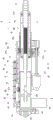
Fig. 7 isbase:Sub>A sectional viewbase:Sub>A-base:Sub>A of fig. 5.
Fig. 8 is a sectional view B-B of fig. 5.
Fig. 9 is a cross-sectional view C-C of fig. 5.
Fig. 10 is a cross-sectional view D-D of fig. 6.
Fig. 11 is a side view showing a steering device according to a first example of the embodiment of the present invention. Fig. 11 (a) shows a state in which the column holder is moved to the rearmost side with respect to the fixed bracket and the upper column is moved to the rearmost side with respect to the column holder, fig. 11 (B) shows a state in which the column holder is moved to the foremost side with respect to the fixed bracket and the upper column is moved to the rearmost side with respect to the column holder, fig. 11 (C) shows a state in which the column holder is moved to the rearmost side with respect to the fixed bracket and the upper column is moved to the foremost side with respect to the column holder, and fig. 11 (D) shows a state in which the column holder is moved to the foremost side with respect to the fixed bracket and the upper column is moved to the foremost side with respect to the column holder.
Fig. 12 is an exploded perspective view of a steering column device according to a first example of the embodiment of the present invention.
Fig. 13 is an exploded perspective view of a steering column device according to a first example of the embodiment of the present invention, as viewed from the side opposite to fig. 12 in the width direction.
Fig. 14 is a side view showing the fixing bracket and the lower telescopic actuator taken out from the steering column apparatus according to the first example of the embodiment of the present invention.
Fig. 15 is a perspective view showing the fixing bracket and the lower telescopic actuator taken out of the steering column device according to the first example of the embodiment of the present invention.
Fig. 16 is a perspective view showing a displacement bracket taken out of the steering column device according to the first example of the embodiment of the present invention.
Fig. 17 is a diagram corresponding to fig. 9, showing a second example of the embodiment of the present invention.
Fig. 18 is a perspective view showing a fixing bracket, a lower telescopic actuator, a reaction force applying device, and a linear guide taken out of a steering device according to a second example of the embodiment of the present invention.
Fig. 19 is a perspective view showing the fixed bracket, the displacement bracket, the lower telescopic actuator, the reaction force applying device, and the linear guide taken out from the steering device according to the second example of the embodiment of the present invention.
Fig. 20 is a cross-sectional view showing a steering device according to a third example of the embodiment of the present invention, and corresponds to fig. 7.
Fig. 21 is a cross-sectional view showing a steering device according to a fourth example of the embodiment of the present invention, and corresponds to fig. 7.
Description of the symbols
1. Steering device
2. Steering column device
3. Steering shaft
4. Reaction force applying device
5. Steering column
6. Actuator for lower expansion and contraction
7. Actuator for upper expansion and contraction
8. Tilting actuator
9. Fixing bracket
10. Column holder
11 upper column
12. 12a Linear guide (Low friction sliding parts)
13. Fixing plate part
13a base
13b bent part
13c flange part
14. Fixed side bracket part
15. Through hole
16 mounting bolt
17a, 17b fixing side plate parts
18 fixed side connecting part
19. 19a displacement bracket
20. Lower column
21. Displacement plate part
21b thick part
21c thin wall part
22a, 22b hanging plate part
23 swing support bracket part
24a, 24b displacement side plate part
25. Displacement side joint part
26. Groove
27. Concave part
28. Guide rail
29. 29a slide block
30 supporting bolt
31. 31a supporting bolt
32. Large diameter part
33. Small diameter part
34. Slit
35a, 35b threaded holes
36a, 36b liners
37a, 37b screw plug
38. Feed screw device for tilting
39. Inner column
40. Shell body
41. Screw shaft
42. Pivot support shaft part
43. Nut
44. Bearing device
45. Cylindrical part
46. Flange part
47. Through hole
48. Fixing bolt
49. Pivot support bolt
50. Motor for lower side expansion
51. Lower feed screw device
52. Screw shaft
53. Nut
54. Motor for upper side extension
55. Upside feed screw device
56. Screw shaft
57. Nut
58. Motor for tilting
59. Inner shaft
60. Outer shaft
61a, 61b radial rolling bearing
63. 63a via hole
64. 64a screw hole
65. Main body part
66. Flange part
67. Steering system
68. Steering wheel
69. Steering wheel
70. Rudder device
71. Actuator
72. Steering tie rod
80 rolling element (Low friction sliding element)
81. 82 groove part
90 sliding parts (Low friction sliding parts)
91. 92 groove part
S imaginary plane
Thickness of D1, D2, D3
d1, d2, d3 thickness
Detailed Description
A first example of an embodiment of the present invention will be described with reference to fig. 1 to 16. The present example is an example in which the steering column device of the present invention is incorporated into a steering device of a steer-by-wire steering system. The steer-by-wire type steering system 67 is formed by electrically connecting the steering device 1 and a steering device 70 for applying a steering angle to a pair of steering wheels 69, and the steering device 1 includes a steering wheel 68 and a sensor (not shown) for measuring a steering amount of the steering wheel 68. That is, in the steer-by-wire type steering system 67, the amount of operation of the steering wheel 68 by the driver is measured by the sensor of the steering device 1. Then, based on the output signal of the sensor, the actuator 71 of the steering device 70 is driven to displace a linear motion shaft such as a rack shaft or a screw shaft disposed in the vehicle width direction, and push and pull the pair of tie rods 72 to provide a steering angle to the pair of steering wheels 69.
The steering device 1 of the present example includes: a steering column device 2, a steering shaft 3, and a reaction force applying device 4. In addition, regarding the steering device 1, the front-rear direction, the up-down direction, and the width direction refer to the front-rear direction, the up-down direction, and the width direction of the vehicle in a state where the steering device 1 is mounted on the vehicle.
The steering column device 2 includes a steering column 5, a lower expansion/contraction actuator 6, an upper expansion/contraction actuator 7, and a tilt actuator 8.
The steering column 5 includes a fixing bracket 9, a column holder 10, an upper column 11, and a linear guide 12, and is configured to be capable of extending and contracting in its entire length. Specifically, the steering column 5 is formed by combining the fixing bracket 9 and the column holder 10 so as to be relatively displaceable in the axial direction via the linear guide 12, and combining the column holder 10 and the upper column 11 so as to be relatively displaceable in the axial direction.
The fixing bracket 9 includes a fixing plate portion 13 and a fixing-side bracket portion 14.
The fixing plate portion 13 has a rectangular shape elongated in the front-rear direction when viewed from the top-bottom direction, and has through holes 15 penetrating in the top-bottom direction at 2 positions in the front-rear direction on each of both side portions in the width direction. The fixing bracket 9 is supported and fixed to a vehicle body, not shown, by a mounting bolt 16 inserted from below through a through hole 15 of the fixing plate portion 13. As shown in fig. 7 to 9, the fixing plate portion 13 includes, in a cross-sectional view taken from the front-rear direction: a base portion 13a disposed at a widthwise intermediate portion; a pair of bent portions 13b bent downward from both ends in the width direction of the base portion 13 a; and a flange portion 13c extending outward in the width direction from the lower end of each of the pair of bent portions 13 b. The bent portion 13b is inclined outward in the width direction as it goes downward. The through hole 15 is formed in the flange portion 13 c.
The fixed-side bracket portion 14 has a substantially U-shape when viewed from the front-rear direction, and is fixedly provided at the front end portion of the fixed plate portion 13. That is, the fixed-side bracket portion 14 includes: a pair of fixed- side plate portions 17a, 17b that hang downward from both widthwise end portions of the front end portion of the fixed plate portion 13; and a fixed-side coupling portion 18 that couples lower end portions of the fixed- side plate portions 17a, 17b to each other. In other words, the fixed-side connecting portion 18 is bridged between the lower end portions of the pair of fixed- side plate portions 17a and 17 b.
The column holder 10 includes: a displacement bracket 19 supported so as to be relatively displaceable in the axial direction (front-rear direction) with respect to the fixed bracket 9; and a lower column 20 supported to be swingable in the vertical direction with respect to the displacement bracket 19.
The displacement bracket 19 includes a displacement plate portion 21, a pair of hanging plate portions 22a, 22b, and a swinging support frame portion 23.
The displacement plate portion 21 has a rectangular shape elongated in the front-rear direction when viewed from the up-down direction, and has a recess 27 on the upper surface of the front side portion. As shown in fig. 7 to 9, the displacement plate portion 21 includes, in a cross-sectional view taken from the front to the rear: a thick portion 21b disposed at a widthwise intermediate portion; and thin portions 21c connected to both sides of the thick portion 21b in the width direction, the thin portions 21c having a smaller thickness than the thick portion 21 b. The thick portion 21b faces the base portion 13a of the fixing plate portion 13 with a gap therebetween in the vertical direction. A recess 27 is formed in the upper surface of the front portion of the thick portion 21 b. As described later, the linear guide 12 is disposed in the recess 27. The thin portion 21c faces a corner portion, which is a connecting portion between the bent portion 13b and the flange portion 13c of the fixed plate portion 13, with a slight gap therebetween.
The pair of hanging plate portions 22a, 22b hang downward from the end portions on both sides in the width direction from the front side portion to the middle portion of the displacement plate portion 21.
The swing support frame portion 23 has a substantially U-shape when viewed from the front-rear direction, and is fixedly provided at an end portion on the rear side of the displacement plate portion 21. That is, the swinging support frame portion 23 includes: a pair of displacement side plate portions 24a, 24b that hang down from both widthwise end portions of the rear end portion of the displacement plate portion 21; and a displacement-side connecting portion 25 that connects lower end portions of the pair of displacement- side plate portions 24a, 24b to each other. Of the pair of displacement- side plate portions 24a, 24b, the displacement-side plate portion 24a on one side in the width direction (the right side in fig. 6 to 8, and the left side in fig. 9) has a recessed groove 26 (see fig. 16) extending in the vertical direction on the inner side surface in the width direction. The displacement-side coupling portion 25 has a circular hole penetrating in the vertical direction at one widthwise portion.
The displacement bracket 19 is supported by the linear guide 12 so as to be relatively displaceable in the axial direction with respect to the fixed bracket 9. That is, in this example, the fixed bracket 9 constitutes the first column member, and the displacement bracket 19 constitutes the second column member. Further, a linear guide 12 as a low-friction sliding member having a low friction coefficient and excellent sliding characteristics is disposed in a portion between the fixed bracket 9 and the displacement bracket 19.
The linear guide 12 includes: a guide rail 28 having a rectangular shape elongated in the axial direction (front-rear direction); and 2 sliders 29 each having a substantially U-shaped configuration when viewed in the axial direction and combined with the guide rail 28 so as to be displaceable in the axial direction along the guide rail 28. In this example, the guide rail 28 is coupled and fixed to the lower surface of the base portion 13a of the fixing plate portion 13 of the fixing bracket 9 by a plurality of support bolts 30. The sliders 29 are coupled and fixed to the inside of the recess 27 of the thick portion 21b of the displacement bracket 19 by a plurality of support bolts 31. That is, the displacement bracket 19 has through holes 63 that penetrate the displacement plate portion 21 in the vertical direction at a plurality of locations in the axial direction in the width direction 2 of the displacement plate portion 21 with the center axis of the steering column 5 interposed therebetween. The upper end of each through hole 63 opens at the bottom surface of the recess 27. The slider 29 has screw holes 64 at 2 positions on both sides of the lower surface in the width direction and spaced apart in the axial direction. The slider 29 is supported and fixed inside the recess 27 of the thick portion 21b of the displacement bracket 19 by screwing the support bolt 31 inserted through the through hole 63 from below into the screw hole 64. Thereby, the displacement bracket 19 is supported so as to be relatively displaceable in the axial direction with respect to the fixed bracket 9.
Here, the linear guide 12 is preferably disposed at a position inward in the width direction of the outer peripheral surface of the lower column 20. In fig. 7, a pair of imaginary planes S that contact both width-direction end portions of the outer peripheral surface of the lower column 20 and extend in the vertical direction are indicated by broken lines. In addition, the linear guide 12 is disposed in a region T sandwiched by the pair of virtual planes S in the width direction. Therefore, the steering column device 2 can be made more compact in the width direction than in the case where the low-friction sliding member such as the linear guide 12 is disposed outside the outer peripheral surface of the lower column 20 in the width direction.
Further, as described above, since the linear guide 12 is disposed on the thick portion 21b of the displacement plate portion 21 of the displacement bracket 19, sufficient rigidity can be ensured.
Further, as in the case of the linear guide 12, the thick portion 21b of the displacement plate portion 21 is also preferably disposed on the inner side in the width direction than the outer peripheral surface of the lower column 20. That is, the thick portion 21b of the displacement plate portion 21 is disposed in the region T sandwiched by the pair of virtual planes S in the width direction. Therefore, the steering column device 2 can be made more compact in the width direction than in the case where the thick portion 21b of the displacement plate portion 21 is disposed at the outer side in the width direction than the outer peripheral surface of the lower pillar 20.
In a portion adjacent to the portion where the linear guide 12 is arranged, the thickness of the thick portion 21b of the displacement plate portion 21 of the displacement bracket 19 is set to be larger than the thickness of the base portion 13a of the fixed bracket 9. More specifically, the thickness D1 of the portion of the thick portion 21b adjacent to the portion (the recess 27) where the linear guide 12 is arranged is set to be larger than the thickness D1 of the portion of the base portion 13a adjacent to the portion where the linear guide 12 is arranged in a direction (the vertical direction) perpendicular to the sliding direction (the front-rear direction) of the linear guide 12 and the direction (the width direction) in which the linear guide 12 is restricted from being displaced by the recess 27 of the displacement plate portion 21. This makes it possible to ensure rigidity while making the steering column device 2 compact in the width direction.
Further, as the linear guide 12, any one of a slide type linear guide, a ball circulation type linear guide, and a non-circulation roller type linear guide may be used. The slide type linear guide is formed by engaging an engaging convex portion formed on the slider with a guide groove formed on the guide. In the ball circulation type linear guide, a plurality of balls are arranged in a load path provided between a guide rail and a slider so as to be capable of rolling, and a circulation path for returning the balls, which have moved to an end point of the load path in accordance with relative displacement between the guide rail and the slider, to a start point of the load path is provided inside the slider. The non-circulating roller type linear guide brings a plurality of rollers rotatably supported by the slider into rolling contact with rolling surfaces formed on the guide rails.
The illustrated linear guide 12 includes 2 sliders 29 (see fig. 15). However, in the case of carrying out the present invention, the number of the sliders of the linear guide may be 1 or 3 or more.
The lower column 20 has a substantially cylindrical shape and is supported to be swingable in the vertical direction with respect to the displacement bracket 19. The lower column 20 has a large diameter portion 32 at a front side portion and a small diameter portion 33 having an inner diameter smaller than the large diameter portion 32 at a rear side portion. The lower column 20 has a slit 34 extending in the axial direction on the lower surface of an axially intermediate portion (a portion from the rear side portion of the large diameter portion 32 to the front side end portion of the small diameter portion 33), and screw holes 35a and 35b on the upper surfaces of the front side end portion of the large diameter portion 32 and the front side end portion of the small diameter portion 33, respectively. Screw plugs 37a and 37b are screwed into the screw holes 35a and 35b, respectively, and pads 36a and 36b made of a material having a small friction coefficient, such as Polyacetal (POM), are bonded and fixed to distal end portions of the screw plugs 37a and 37b.
In this example, the rear portion of the lower column 20 is supported via a tilt feed screw device 38 (see fig. 16) constituting the tilt actuator 8 so as to be vertically displaceable with respect to the swing support frame portion 23 of the displacement bracket 19. The front portion of the lower column 20 is pivotally supported by the fixed-side bracket portion 14 of the fixed bracket 9 supported by the vehicle body via the inner column 39 and the case 40 of the reaction force applying device 4.
The tilt feed screw device 38 includes: a screw shaft 41 having an external thread portion on an outer peripheral surface thereof; and a nut 43 having a female screw portion screwed to the male screw portion on an inner peripheral surface thereof and a cylindrical pivot shaft portion 42 on an outer peripheral surface thereof. In this example, the screw shaft 41 is rotatably supported inside the concave groove 26 of the displacement side plate portion 24a on one side in the width direction of the rocking support frame portion 23 and the circular hole formed in the displacement side connecting portion 25 via a bearing device 44 such as a radial rolling bearing and/or a sliding bearing, and the pivot support shaft portion 42 of the nut 43 is supported (pivotally supported) in a pivot support concave portion formed in the outer peripheral surface of the rear portion (the small diameter portion 33) of the lower column 20. Therefore, when the nut 43 is displaced in the axial direction (vertical direction) of the screw shaft 41 along the screw shaft 41 in accordance with the rotation of the screw shaft 41, the rear side portion of the lower column 20 is displaced in the vertical direction with respect to the swing support frame portion 23 of the displacement bracket 19.
The inner column 39 includes a cylindrical portion 45 and a flange portion 46 bent radially outward from a front end of the cylindrical portion 45. The inner column 39 is combined with the lower column 20 so as to be relatively displaceable in the axial direction of the lower column 20. Specifically, the rear portion of the cylindrical portion 45 is fitted into the large-diameter portion 32 of the lower column 20 with a clearance, and the packing 36a of the screw plug 37a screwed into the screw hole 35a on the front side of the lower column 20 is brought into contact with the outer peripheral surface of the rear portion of the cylindrical portion 45. Thus, the inner column 39 is fitted into the lower column 20 so as to be relatively displaceable in the axial direction of the lower column 20.
Since the screw plug 37a does not directly abut against the outer peripheral surface of the cylindrical portion 45, but the packing 36a provided at the distal end portion of the screw plug 37a abuts against the outer peripheral surface of the cylindrical portion 45, the abutting force can be easily adjusted. Further, the abutting force can be easily adjusted by adjusting the fastening torque of the screw plug 37a. In this way, the sliding friction force between the packing 36a and the outer peripheral surface of the cylindrical portion 45 can be adjusted when the inner column 39 and the lower column 20 are relatively displaced in the axial direction. Further, the abutting force of the pad 36a against the cylindrical portion 45 may be adjusted using an elastic member such as a spring. In the illustrated example, one screw hole 35a is formed in the front side of the lower column 20, and a screw plug 37a having a packing 36a is screwed into the one screw hole 35a, but a plurality of screw holes 35a may be provided, and a screw plug 37a having a packing 36a is screwed into each of the plurality of screw holes 35 a.
The housing 40 of the reaction force applying device 4 is supported and fixed to the inner column 39 by a fixing bolt 48 inserted through a through hole 47 from the rear side, and the through hole 47 is formed in the flange portion 46 of the inner column 39. The housing 40 is pivotally supported by the fixing bracket 9 by a pivot support bolt 49, and the pivot support bolt 49 is inserted through a through hole formed in the fixing side plate portions 17a and 17b of the fixing side bracket portion 14.
Therefore, as the screw shaft 41 rotates, the nut 43 is displaced in the vertical direction, and thereby when the rear portion of the lower column 20 is displaced in the vertical direction with respect to the swing support bracket portion 23 of the displacement bracket 19, the lower column 20 swings in the vertical direction about the pivot support bolt 49.
The upper column 11 has a substantially cylindrical shape and is combined with the column holder 10 so as to be relatively displaceable in the axial direction. Specifically, the front portion of the upper column 11 is fitted into the small-diameter portion 33 of the lower column 20 with a clearance, and the packing 36b of the screw plug 37b screwed into the screw hole 35b on the rear side of the lower column 20 is brought into contact with the outer peripheral surface of the front portion of the upper column 11. Thereby, the upper column 11 is fitted into the lower column 20 so as to be relatively displaceable in the axial direction of the lower column 20.
In this way, since the screw plug 37b does not directly abut against the outer peripheral surface of the upper column 11, but the packing 36b provided at the distal end portion of the screw plug 37b abuts against the outer peripheral surface of the upper column 11, the abutting force can be easily adjusted. Further, the abutting force can be easily adjusted by adjusting the fastening torque of the screw plug 37b. In this way, the sliding frictional force between the pad 36b and the outer peripheral surface of the upper column 11 when the upper column 11 and the lower column 20 are relatively displaced in the axial direction can be adjusted. Further, the contact force of the spacer 36b with respect to the outer peripheral surface of the upper column 11 may be adjusted using an elastic member such as a spring. In the illustrated example, one screw hole 35b is formed in the rear side of the lower column 20, and the screw plug 37b having the packing 36b is screwed into the one screw hole 35b, but a plurality of screw holes 35b may be provided, and the screw plugs 37b having the packing 36b are screwed into the plurality of screw holes 35b, respectively.
The lower telescopic actuator 6 includes a lower telescopic motor 50, and displaces the column holder 10 in the axial direction with respect to the fixed bracket 9 using the lower telescopic motor 50 as a drive source. In this example, the lower expansion/contraction actuator 6 constitutes an expansion/contraction actuator, and the lower expansion/contraction motor 50 constitutes an expansion/contraction motor. The lower telescopic actuator 6 further includes a lower feed screw device 51, and the lower feed screw device 51 converts the rotational motion of the output shaft of the lower telescopic motor 50 into a linear motion.
The lower feed screw device 51 includes: a screw shaft 52 having a male screw portion on an outer peripheral surface thereof and rotationally driven by the lower expansion/contraction motor 50; and a nut 53 having a female screw portion on an inner peripheral surface thereof to be screwed with the male screw portion.
In this example, the screw shaft 52 is supported to be rotatable only with respect to the fixing bracket 9, and the nut 53 is supported and fixed to the displacement bracket 19 of the column holder 10. Specifically, the screw shaft 52 is rotatably fixed to the widthwise outer surface (widthwise other side surface) of the fixed-side plate portion 17b on the other widthwise side (left side in fig. 6 to 8, right side in fig. 9) of the fixed-side bracket portion 14 of the fixed bracket 9, and the nut 53 is supported and fixed to the widthwise outer surface of the hanging-down plate portion 22b on the other widthwise side of the displacement bracket 19. The lower telescopic motor 50 is supported and fixed to the fixed-side bracket portion 14. Therefore, when the nut 53 is displaced in the front-rear direction along the screw shaft 52 as the screw shaft 52 is rotationally driven by the lower telescopic motor 50 via a speed reducing mechanism such as a worm gear reducer, the displacement bracket 19 is displaced in the axial direction of the fixed bracket 9, that is, in the front-rear direction with respect to the fixed bracket 9.
The upper telescopic actuator 7 includes an upper telescopic motor 54, and displaces the upper column 11 in the axial direction with respect to the column holder 10 using the upper telescopic motor 54 as a drive source. In this example, the upper telescopic actuator 7 further includes an upper feed screw device 55, and the upper feed screw device 55 converts the rotational motion of the output shaft of the upper telescopic motor 54 into a linear motion.
The upper feed screw device 55 includes: a screw shaft 56 having an external thread portion on an outer peripheral surface thereof and rotationally driven by the upper expansion/contraction motor 54; and a nut 57 having a female screw portion on an inner peripheral surface thereof to be screwed with the male screw portion.
In this example, the screw shaft 56 is supported rotatably only with respect to the lower column 20 of the column holder 10, and the nut 57 is supported and fixed to the upper column 11. More specifically, the screw shaft 56 is supported rotatably only with respect to the lower surface of the front portion of the large diameter portion 32 of the lower column 20, and the nut 57 is supported and fixed to the lower surface of the front portion of the upper column 11. The upper telescopic motor 54 is supported and fixed to the lower column 20. Therefore, when the nut 57 is displaced in the front-rear direction along the screw shaft 56 as the screw shaft 56 is rotationally driven by the upper telescopic motor 54 via a speed reducing mechanism such as a worm reducer, the upper column 11 is displaced in the axial direction of the lower column 20, that is, in the front-rear direction with respect to the lower column 20.
The tilt actuator 8 includes a tilt motor 58 and a tilt feed screw device 38. The tilt actuator 8 rotates the screw shaft 41 of the tilt feed screw device 38 via a speed reduction mechanism such as a worm reducer by the tilt motor 58, and moves the nut 43 in the vertical direction along the screw shaft 41, thereby vertically displacing the rear portion of the lower column 20 with respect to the displacement bracket 19.
The steering shaft 3 is configured by combining an inner shaft 59 and an outer shaft 60 so as to be relatively displaceable in the axial direction and not rotatable relative to each other. In this example, the steering shaft 3 is formed by spline-engaging a rear portion of the front inner shaft 59 with a front portion of the rear outer shaft 60.
The steering shaft 3 is rotatably supported on the inside of the steering column device 2 in the radial direction of the steering column 5. Specifically, the front end of the outer shaft 60 is rotatably supported by the front end of the upper column 11 via a radial rolling bearing 61a, and the rear end of the outer shaft 60 is rotatably supported by the rear end of the upper column 11 via a radial rolling bearing 61 b. Therefore, the steering shaft 3 extends and contracts together with the steering column 5.
A steering wheel 68 is supported at a rear end of the steering shaft 3, i.e., a rear end of the outer shaft 60. Further, a reaction force applying device 4 for applying an operation reaction force to the steering wheel 68 is connected to a front end portion of the steering shaft 3, that is, a front end portion of the inner shaft 59.
The reaction force applying device 4 includes a housing 40, a reaction force applying motor (not shown), and a speed reducer. When the driver operates the steering wheel 68, the reaction force application device 4 drives the reaction force application motor, increases the torque of the reaction force application motor by the reduction gear housed inside the housing 40, and then applies the torque to the steering shaft 3. Thereby, an operation reaction force is applied to the steering wheel 68. The magnitude of the reaction force applied to the steering wheel 68 is determined by the steering angle of the steering wheel 68 obtained by the sensor, the torque applied to the steering shaft 3, and the like. The reduction gear is constituted by a worm reduction gear, for example.
In the steering device 1 of this example, when adjusting the forward/backward position of the steering wheel 68, the column holder 10 (displacement bracket 19) is displaced relative to the fixed bracket 9 in the axial direction (forward/backward direction) based on the energization of the lower telescopic motor 50, and/or the upper column 11 is displaced relative to the column holder 10 (lower column 20) in the axial direction (forward/backward direction) based on the energization of the upper telescopic motor 54.
That is, the lower stretching motor 50 is energized, the screw shaft 52 of the lower feed screw device 51 is rotationally driven by the lower stretching motor 50, and the nut 53 is displaced in the front-rear direction, whereby the displacement bracket 19 is displaced in the axial direction of the fixed bracket 9, that is, in the front-rear direction with respect to the fixed bracket 9. And/or, the upper telescopic motor 54 is energized, the screw shaft 56 of the upper feed screw device 55 is rotationally driven by the upper telescopic motor 54, and the nut 57 is displaced in the front-rear direction, thereby displacing the upper column 11 relative to the lower column 20 in the axial direction of the lower column 20, that is, in the front-rear direction. Thus, the longitudinal position of the steering wheel 68 is adjusted by extending and contracting the entire length of the steering column 5 and the entire length of the steering shaft 3. After the front-rear position of the steering wheel 68 is adjusted to a desired position, the energization of the lower expansion/contraction motor 50 and/or the upper expansion/contraction motor 54 is stopped.
When the up-down position of the steering wheel 68 is adjusted, the rear portion of the lower column 20 is displaced in the up-down direction with respect to the displacement bracket 19 by energization of the tilt motor 58. That is, the tilt motor 58 is energized, the screw shaft 41 of the tilt feed screw device 38 is rotationally driven by the tilt motor 58, and the nut 43 is displaced in the vertical direction, whereby the lower column 20 is swung about the pivot support bolt 49, and the rear portion of the lower column 20 is displaced in the vertical direction. Thus, the rear end of the steering shaft 3 rotatably supported on the radially inner side of the steering column 5 is displaced in the vertical direction, and the vertical position of the steering wheel 68 is adjusted. After the vertical position of the steering wheel 68 is adjusted to a desired position, the energization of the tilt motor 58 is stopped.
The adjustment of the front-rear position and the adjustment of the up-down position of the steering wheel 68 may be performed simultaneously or may be performed independently (sequentially in time).
In this example, the steering column 5 is configured by combining the fixing bracket 9 and the column holder 10 so as to be relatively displaceable in the axial direction, and combining the column holder 10 and the upper column 11 so as to be relatively displaceable in the axial direction. That is, the steering column 5 has a 2-stage telescopic structure. Therefore, the amount of expansion and contraction of the entire length of the steering column 5 can be sufficiently secured, and the axial dimensions of the screw shaft 52 of the lower feed screw device 51 and the screw shaft 56 of the upper feed screw device 55 can be prevented from becoming excessively large.
The steering column device 2 of the present example is configured such that the column holder 10 is displaced in the axial direction with respect to the fixing bracket 9 by the lower telescopic actuator 6, and the upper column 11 is displaced in the axial direction with respect to the column holder 10 by the upper telescopic actuator 7. Therefore, even when a trouble such as a failure occurs in one of the lower expansion/contraction actuator 6 and the upper expansion/contraction actuator 7, the front-rear position of the steering wheel 68 can be adjusted by the other actuator.
In the steering column device 2 of the present example, the lower telescopic motor 50 of the lower telescopic actuator 6 and the upper telescopic motor 54 of the upper telescopic actuator 7 are energized simultaneously, whereby the upper column 11 can be displaced in the axial direction with respect to the column holder 10 while the column holder 10 is displaced in the axial direction with respect to the fixing bracket 9. Therefore, compared to a structure in which the entire length of the steering column is extended and contracted by 1 electric motor, it is easy to increase the extension and contraction speed of the steering column 5.
In particular, in the steering column device 2 of this example, the fixing bracket 9 and the column holder 10 (displacement bracket 19) are combined via the linear guide 12 having high component accuracy and assembly accuracy. Therefore, it is possible to achieve both of securing the support rigidity of the column holder 10 with respect to the fixed bracket 9 and reducing the resistance (displacement resistance) to axial displacement of the column holder 10 with respect to the fixed bracket 9 at a high level. Further, by reducing the displacement resistance of the column holder 10, the lower telescopic actuator 6 for relatively displacing the column holder 10 in the axial direction with respect to the fixed bracket 9 can be downsized, and the operating sound when relatively displacing the column holder 10 in the axial direction with respect to the fixed bracket 9 can be suppressed to be small.
Further, by combining the fixing bracket 9 and the column holder 10 via the linear guide 12, the expansion and contraction speed of the steering column 5 can also be increased. In particular, when the amount of adjustment of the front-rear position of the steering wheel 68 is large, such as when the steering wheel 68 is housed inside the instrument panel or when the steering wheel 68 housed inside the instrument panel is expanded, the effect obtained by increasing the expansion/contraction speed of the steering column 5 can be remarkably obtained.
Further, since the fixing bracket 9 and the column holder 10 are combined via the linear guide 12, it is possible to sufficiently secure rigidity against: a downward force applied from the steering wheel 68 to the steering column 5 when the driver gets on or off the vehicle with the handle placed on the steering wheel 68, and a left-right force applied from the steering wheel 68 to the steering column 5 during cornering.
In the steering device 1 of this example, when adjusting the forward/rearward position of the steering wheel 68, for example, after the fixing bracket 9 is axially and largely displaced relative to the column holder 10 at a high speed, the forward/rearward position of the steering wheel 68 can be adjusted to a desired position by finely adjusting the amount of axial displacement of the column holder 10 relative to the fixing bracket 9 and/or the amount of axial displacement of the upper column 11 relative to the column holder 10.
In this example, the guide rail 28 of the linear guide 12 is coupled and fixed to the lower surface of the fixed plate portion 13 of the fixed bracket 9 by a plurality of support bolts 30, and the slider 29 is coupled and fixed to the upper surface of the displacement plate portion 21 of the displacement bracket 19 by a plurality of support bolts 31. Since the linear guide 12 has high component accuracy and assembly accuracy, it is not necessary to adjust the resistance to displacement (displacement resistance) of the column holder 10 in the axial direction with respect to the fixed bracket 9 after the fixed bracket 9 and the column holder 10 are combined via the linear guide 12. In short, according to the steering column device 2 of the present example, even when the steering column 5 has a 2-stage telescopic structure, the structure can be simplified, and the assembly cost can be kept low.
In particular, even when the ball circulation type linear guide is used as the linear guide 12, since the component accuracy and the assembly accuracy are high and the rolling balls do not shake, it is not necessary to readjust the preload after the fixing bracket 9 and the column holder 10 are combined. In the steering column described in the specification of U.S. patent application publication No. 2019/210632, it is necessary to combine the sleeves so that a plurality of balls are sandwiched between the sleeves and the sleeves are fitted to each other, and there is a possibility that the assembly work becomes complicated. In contrast, when the ball circulation type linear guide is used as the linear guide 12 of the present example, the balls are combined in advance with the linear guide 12 and are unitized, so that the assembly work can be facilitated.
In this example, the linear guide 12 is disposed in the upper portion of the portion between the fixed bracket 9 and the displacement bracket 19, but in the case of implementing the present invention, the linear guide may be disposed in the lower portion of the portion between the fixed bracket and the displacement bracket. Alternatively, the linear guides may be disposed on both widthwise side portions of the portion between the fixed bracket and the displacement bracket. In this case, 1 linear guide is disposed on each of both sides in the width direction of the portion between the fixed bracket and the displacement bracket.
In this example, the fixing bracket 9 and the column holder 10 (displacement bracket 19) are combined via the linear guide 12, but instead of or in addition to this, the column holder (lower column) and the upper column may be combined via the linear guide.
In this example, a case where the present invention is applied to the steering column device 2 has been described, and the steering column device 2 includes both the telescopic mechanism for adjusting the front-rear position of the steering wheel 68 and the tilt mechanism for adjusting the up-down position, but the present invention can also be applied to a steering column device including only the telescopic mechanism. In this example, although the description has been given of the case where the steering column device of the present invention is applied to a steering device of a steer-by-wire steering system, the steering column device of the present invention is not limited to this, and can be applied to a mechanical steering system in which the front end portion of the steering shaft is mechanically connected to the input shaft (pinion shaft) of the steering gear unit via a universal joint and an intermediate shaft. In addition, the mechanical steering system may include an assist device for reducing the force required by the driver to operate the steering wheel. That is, the steering column device of the present invention can be applied to a power steering system such as an electric power steering system.
Further, the steering column 5 of the present example has a 2-stage telescopic structure, but the present invention can also be applied to a steering column device in which the steering column has a 1-stage telescopic structure.
[ second example of embodiment ]
A second example of the embodiment of the present invention will be described with reference to fig. 17 to 19. The steering column device 2 of the present embodiment differs from the steering column device 2 of the first embodiment in the support structure of the slider 29a constituting the linear guide 12a with respect to the displacement bracket 19 a. Specifically, the position of the support bolt 31a for supporting the slider 29a with respect to the displacement bracket 19a is located on the outer side in the width direction than the first example of the embodiment.
The displacement bracket 19a has through holes 63a penetrating the displacement plate portion 21 in the vertical direction at a plurality of positions in the axial direction of each of the positions 2 in the width direction with the center axis of the steering column 5a interposed therebetween in the displacement plate portion 21. In this example, the through holes 63a are formed at a plurality of positions in the axial direction at the positions of the positions 2 in the width direction of the portion of the displacement plate portion 21 where the recess 27 is formed.
The slider 29a of the linear guide 12a has a substantially rectangular columnar shape, and includes on the upper surface: a main body portion 65 having an engaging portion that is capable of engaging with the rail 28 so as to be displaced in the axial direction along the rail 28; and a pair of flange portions 66 that protrude outward in the width direction from upper end portions of both lateral side surfaces of the main body portion 65. The slider 29a has screw holes 64a at a plurality of axial positions on the lower surface of each flange 66.
The slider 29a is supported and fixed to the upper surface of the displacement bracket 19a by screwing the support bolt 31a inserted from below through the through hole 63a into the screw hole 64a formed in the flange portion 66 in a state where the lower portion of the body portion 65 is engaged with (disposed inside) the recess 27 of the displacement bracket 19 a.
In this example, the position of the support bolt 31a for supporting the slider 29a to the displacement bracket 19a is located outward in the width direction than the first example of the embodiment. Therefore, the support rigidity of the slider 29a with respect to the displacement bracket 19a is easily ensured. In addition, a sufficient vertical distance (gap) can be secured between the head of the support bolt 31a and the upper surface of the lower column 20. As a result, a sufficient amount of vertical swingable movement of the lower column 20 with respect to the displacement bracket 19a (an amount of vertical adjustment of the steering wheel) can be ensured. The structure and the operation and effects of the other portions are the same as those of the first example of the embodiment.
[ third example of embodiment ]
A third example of the embodiment of the present invention will be explained. Fig. 20 is a sectional view showing the steering device of the present embodiment, and corresponds to fig. 7. In this example, a rolling member 80 as a low-friction sliding member is disposed in a portion between the fixed bracket 9 and the displacement bracket 19. The rolling members 80 may be exemplified by steel spherical and cylindrical rolling elements. In the illustrated example, spherical rolling elements are used.
The pair of bent portions 13b of the fixing plate portion 13 of the fixing bracket 9 and the pair of thick portions 21b of the displacement plate portion 21 of the displacement bracket 19 face each other in the width direction. Grooves 82 and 81 in which the rolling member 80 can be disposed are formed in the facing surfaces of the pair of bent portions 13b and the pair of thick portions 21b, respectively. The rolling member 80 is disposed between these grooves 82 and 81. The number of rolling members 80 is not particularly limited, and a plurality of rolling members 80 may be arranged in the front-rear direction.
Thus, the displacement bracket 19 is supported by the rolling members 80 so as to be relatively displaceable in the axial direction with respect to the fixed bracket 9. The present embodiment is similar to the linear guides 12 and 12a of the first and second embodiments in that a rolling mechanism is used as a low-friction sliding member. However, in the present embodiment, the pair of rolling members 80 are disposed at two locations (the pair of bent portions 13 b) in the width direction of the fixed bracket 9 so as to face each other in the width direction with the thick portion 21b interposed therebetween, and the fixed bracket 9 and the displacement bracket 19 are configured to have interference in the width direction and the vertical direction, so that operations other than relative movement in the axial direction can be restricted. Further, according to the present embodiment, compared to the case where the linear guides 12 and 12a are used as in the first and second embodiments, the number of components is reduced, and the structure can be simplified, so that the linear guides 12 and 12a can have the same characteristics and the cost can be reduced.
Here, the pair of rolling members 80 is preferably disposed on the inner side in the width direction than the outer peripheral surface of the lower column 20. In fig. 20, a pair of imaginary planes S that contact both width-direction end portions of the outer peripheral surface of the lower column 20 and extend in the vertical direction are shown by broken lines. Further, a pair of rolling members 80 is disposed in a region T sandwiched by a pair of virtual planes S in the width direction. Therefore, the steering column device can be made more compact in the width direction than in the case where the pair of rolling members 80 are disposed at positions further outward in the width direction than the outer peripheral surface of the lower column 20.
Further, since the pair of rolling members 80 are disposed on the thick portion 21b of the displacement plate portion 21 of the displacement bracket 19 as described above, sufficient rigidity can be ensured.
In a portion adjacent to the portion where the rolling member 80 is disposed, the thickness of the thick portion 21b of the displacement plate portion 21 of the displacement bracket 19 is set to be larger than the thickness of the bent portion 13b of the fixed bracket 9. More specifically, the thickness D2 of the portion of the thick portion 21b adjacent to the portion (groove portion 82) where the rolling member 80 is disposed is set to be greater than the thickness D2 of the portion of the bent portion 13b adjacent to the portion (groove portion 81) where the rolling member 80 is disposed, in the sliding direction (front-rear direction) of the rolling member 80, the direction in which the displacement of the rolling member 80 is restricted by the groove portions 82 and 81 (the direction in which the bent portion 13b extends), and the perpendicular direction. This makes it possible to ensure rigidity while making the steering column device 2 compact in the width direction.
In this example, the fixing bracket 9 and the column holder 10 (displacement bracket 19) are combined via the rolling member 80, but instead of or in addition to this, the column holder (lower column) and the upper column may be combined via the rolling member 80.
[ fourth example of embodiment ]
A fourth example of the embodiment of the present invention will be explained. Fig. 21 is a cross-sectional view showing the steering device of the present embodiment, and corresponds to fig. 7. In this example, a sliding member 90 as a low-friction sliding member is disposed in a portion between the fixed bracket 9 and the displacement bracket 19. The slide member 90 of this example is a rectangular parallelepiped shape having a rectangular cross section and extending in the front-rear direction, but the shape is not limited. The slide member 90 is fixed to one of the fixed bracket 9 and the displacement bracket 19, and is guided by the other to slide, thereby allowing the fixed bracket 9 and the displacement bracket 19 to move relative to each other in the axial direction.
The pair of bent portions 13b of the fixing plate portion 13 of the fixing bracket 9 and the pair of thick portions 21b of the displacement plate portion 21 of the displacement bracket 19 face each other in the width direction, and groove portions 92, 91 in which the sliding member 90 can be disposed are formed on the facing surfaces of the pair of bent portions 13b and the pair of thick portions 21b, respectively. A slide member 90 is disposed between these grooves 92 and 91. The slide member 90 is fixed to one of the grooves 92 and 91 by fitting, welding, bonding, or the like, and can slide while being guided by the other. Further, by using a self-lubricating resin such as PTFE (polytetrafluoroethylene resin) as the sliding member 90, friction during operation can be reduced. The material of the sliding member 90 may be appropriately selected from materials other than the self-lubricating resin.
Thus, the displacement bracket 19 is supported by the slide member 90 so as to be capable of relative displacement in the axial direction with respect to the fixed bracket 9. In the present embodiment, the pair of slide members 90 are disposed at two locations in the width direction of the fixing bracket 9 (the pair of bent portions 13 b) so as to face each other in the width direction with the thick portion 21b interposed therebetween, and the fixing bracket 9 and the displacement bracket 19 are configured to have interference in the width direction and the vertical direction, so that operations other than relative movement in the axial direction can be restricted. Further, according to the present embodiment, as compared with the case where the linear guides 12 and 12a are used as in the first and second embodiments, the number of components is reduced, and the structure can be simplified, so that the linear guides 12 and 12a can have the same characteristics and the cost can be reduced.
Here, the pair of slide members 90 are preferably disposed on the inner side in the width direction than the outer peripheral surface of the lower column 20. In fig. 21, a pair of imaginary planes S that contact both width-direction end portions of the outer peripheral surface of the lower column 20 and extend in the vertical direction are shown by broken lines. Further, a pair of sliding members 90 are disposed in a region T sandwiched by a pair of virtual planes S in the width direction. Therefore, the steering column device 2 can be made more compact in the width direction than in the case where the pair of slide members 90 are disposed at positions further outward in the width direction than the outer peripheral surface of the lower column 20.
Further, as described above, since the pair of slide members 90 are disposed on the thick portion 21b of the displacement plate portion 21 of the displacement bracket 19, sufficient rigidity can be ensured.
In a portion adjacent to the portion where the slide member 90 is disposed, the thickness of the thick portion 21b of the displacement plate portion 21 of the displacement bracket 19 is set to be larger than the thickness of the bent portion 13b of the fixed bracket 9. More specifically, the thickness D3 of the portion of the thick portion 21b adjacent to the portion (groove portion 92) where the slide member 90 is disposed is set to be greater than the thickness D3 of the portion of the bent portion 13b adjacent to the portion (groove portion 91) where the slide member 90 is disposed, in the sliding direction (front-rear direction) of the slide member 90, the direction in which the displacement of the slide member 90 is restricted by the groove portions 91 and 92 (direction in which the bent portion 13b extends), and the perpendicular direction. This makes it possible to ensure rigidity while making the steering column device 2 compact in the width direction.
In this example, the fixing bracket 9 and the column holder 10 (displacement bracket 19) are combined via the slide member 90, but instead of or in addition to this, the column holder (lower column) and the upper column may be combined via the slide member 90.
This application is based on japanese patent application 2020-145213, filed on 8/31/2020 and is hereby incorporated by reference in its entirety.
Claims (15)
1. A steering column device is characterized in that,
comprises a steering column and an actuator for extension and contraction,
the steering column has:
a first column member;
a second column member that is combined so as to be relatively displaceable in an axial direction with respect to the first column member; and
a low-friction sliding member disposed in a portion between the first column member and the second column member,
the actuator for extension and contraction has a motor for extension and contraction, and displaces the second column member in the axial direction relative to the first column member using the motor for extension and contraction as a drive source.
2. The steering column device according to claim 1,
the steering column has: a fixing bracket; a post holder combined in such a manner as to be relatively displaceable in an axial direction with respect to the fixing bracket; and an upper column that is combined with the column holder so as to be relatively displaceable in the axial direction, wherein the low-friction sliding member is disposed in a portion between at least one of a portion between the fixing bracket and the column holder and a portion between the column holder and the upper column,
the steering column device is provided with:
a lower telescopic actuator having a lower telescopic motor for displacing the column holder in an axial direction with respect to the fixed bracket using the lower telescopic motor as a driving source; and
and an upper telescopic actuator having an upper telescopic motor, wherein the upper column is displaced in an axial direction with respect to the column holder using the upper telescopic motor as a drive source.
3. The steering column device according to claim 2,
the post holder includes: a displacement bracket supported to be relatively displaceable in an axial direction with respect to the fixed bracket; and a lower column supported to be swingable in an up-down direction with respect to the displacement bracket,
the steering column device further includes a tilt actuator having a tilt motor, and the lower column is displaced in the vertical direction with respect to the displacement bracket using the tilt motor as a drive source.
4. Steering column arrangement according to claim 1,
the steering column has: a fixing bracket; a post holder combined in such a manner as to be relatively displaceable in an axial direction with respect to the fixing bracket; and an upper post combined in such a manner as to be relatively displaceable in the axial direction with respect to the post holder,
the post holder includes: a displacement bracket supported so as to be relatively displaceable in an axial direction with respect to the fixed bracket; and a lower column supported to be swingable in an up-down direction with respect to the displacement bracket,
the low-friction sliding member is disposed on the inner side in the width direction of the outer peripheral surface of the lower column.
5. The steering column device according to claim 4,
a portion of the low-friction sliding member disposed between the fixed bracket and the displacement bracket,
the displacement carriage has a thick-walled portion,
the low-friction sliding member is disposed on the thick portion.
6. The steering column device according to claim 5,
the thick portion is disposed on the inner side in the width direction than the outer peripheral surface of the lower column.
7. The steering column device according to claim 5 or 6,
the thickness of a portion of the thick wall portion adjacent to the portion where the low-friction sliding member is disposed is greater than the thickness of a portion of the fixing bracket adjacent to the portion where the low-friction sliding member is disposed.
8. The steering column device according to any one of claims 1 to 7,
the low-friction sliding member is a linear guide,
the linear guide includes:
a guide rail that is elongated in an axial direction; and
a slider combined with the guide rail so as to be displaceable in an axial direction along the guide rail.
9. The steering column device according to claim 8,
the linear guide is disposed at a portion between the fixing bracket and the displacement bracket.
10. The steering column device according to claim 9,
the displacement bracket has a through hole penetrating in the vertical direction at the upper part,
the slider has a screw hole opened in a lower surface thereof, and is supported and fixed to an upper surface of the displacement bracket by screwing a support bolt inserted through the through hole from below into the screw hole,
the guide rail is supported and fixed on the lower surface of the fixed bracket.
11. The steering column device according to claim 10,
the through hole is disposed at both width-direction side portions across a center axis of the steering column, and the screw hole is disposed at both width-direction side portions across the center axis of the steering column.
12. The steering column device according to any one of claims 1 to 7,
the low-friction sliding member is a rolling member.
13. The steering column device according to claim 12,
the rolling members are disposed at two locations in the width direction so as to face each other in the width direction.
14. The steering column device according to any one of claims 1 to 7,
the low-friction sliding member is a sliding member.
15. The steering column device according to claim 14,
the sliding members are disposed at two locations in the width direction so as to face each other in the width direction.
Applications Claiming Priority (3)
| Application Number | Priority Date | Filing Date | Title |
|---|---|---|---|
| JP2020145213 | 2020-08-31 | ||
| JP2020-145213 | 2020-08-31 | ||
| PCT/JP2021/031858 WO2022045346A1 (en) | 2020-08-31 | 2021-08-31 | Steering column device |
Publications (1)
| Publication Number | Publication Date |
|---|---|
| CN115884912A true CN115884912A (en) | 2023-03-31 |
Family
ID=80353506
Family Applications (1)
| Application Number | Title | Priority Date | Filing Date |
|---|---|---|---|
| CN202180052756.9A Pending CN115884912A (en) | 2020-08-31 | 2021-08-31 | Steering column device |
Country Status (5)
| Country | Link |
|---|---|
| US (1) | US20230311973A1 (en) |
| EP (1) | EP4206058A4 (en) |
| JP (1) | JP7492014B2 (en) |
| CN (1) | CN115884912A (en) |
| WO (1) | WO2022045346A1 (en) |
Families Citing this family (1)
| Publication number | Priority date | Publication date | Assignee | Title |
|---|---|---|---|---|
| DE102023110003A1 (en) * | 2022-10-28 | 2024-05-08 | Schaeffler Technologies AG & Co. KG | Adjustment unit of a steering column |
Family Cites Families (11)
| Publication number | Priority date | Publication date | Assignee | Title |
|---|---|---|---|---|
| US5737971A (en) * | 1996-08-05 | 1998-04-14 | General Motors Corporation | Motor vehicle steering column |
| JP5293643B2 (en) | 2010-03-02 | 2013-09-18 | 日本精工株式会社 | Steering device |
| EP2724915B1 (en) | 2012-05-25 | 2017-12-27 | NSK Ltd. | Position adjustment device for electric steering wheel |
| KR101604263B1 (en) | 2014-12-24 | 2016-03-17 | 남양공업주식회사 | Steering Column Device for Vehicles |
| DE102015000029A1 (en) * | 2015-01-08 | 2016-07-14 | Thyssenkrupp Ag | Steering column with adaptable pivot bearing |
| US9849904B2 (en) * | 2015-07-31 | 2017-12-26 | Steering Solutions Ip Holding Corporation | Retractable steering column with dual actuators |
| JP6602155B2 (en) * | 2015-10-23 | 2019-11-06 | 富士機工株式会社 | Steering column device |
| US9744983B2 (en) * | 2015-12-18 | 2017-08-29 | Steering Solutions Ip Holding Corporation | Steering column assembly |
| US10882548B2 (en) | 2017-10-17 | 2021-01-05 | Steering Solutions Ip Holding Corporation | Stowable steering column apparatus |
| US10640139B2 (en) | 2018-01-08 | 2020-05-05 | Steering Solutions Ip Holding Corporation | Telescoping steering column |
| JP7143235B2 (en) | 2019-03-04 | 2022-09-28 | 株式会社日立製作所 | Iron core for stationary induction electric machine |
-
2021
- 2021-08-31 CN CN202180052756.9A patent/CN115884912A/en active Pending
- 2021-08-31 EP EP21861767.8A patent/EP4206058A4/en active Pending
- 2021-08-31 JP JP2022545763A patent/JP7492014B2/en active Active
- 2021-08-31 US US18/043,170 patent/US20230311973A1/en active Pending
- 2021-08-31 WO PCT/JP2021/031858 patent/WO2022045346A1/en unknown
Also Published As
| Publication number | Publication date |
|---|---|
| EP4206058A1 (en) | 2023-07-05 |
| JP7492014B2 (en) | 2024-05-28 |
| US20230311973A1 (en) | 2023-10-05 |
| EP4206058A4 (en) | 2024-10-16 |
| JPWO2022045346A1 (en) | 2022-03-03 |
| WO2022045346A1 (en) | 2022-03-03 |
Similar Documents
| Publication | Publication Date | Title |
|---|---|---|
| JP5076908B2 (en) | Steering column device | |
| EP1905664A2 (en) | Electrically adjustable telescopic steering apparatus | |
| JP5233671B2 (en) | Tilt-type steering device | |
| JP4325403B2 (en) | Electric steering column device | |
| US8739645B2 (en) | Toothed-rack steering gear, and servo steering system equipped with the same | |
| EP2011718B1 (en) | Vehicle steering column | |
| JP2010083392A (en) | Electric telescopic steering device | |
| JP2002193110A (en) | Electric tilting type steering device for vehicle | |
| CN107021129A (en) | The gap for steering mechanism and preload adjustment using piezoelectric element | |
| CN115884912A (en) | Steering column device | |
| JP2012245810A (en) | Rack shaft supporting device and vehicle steering device | |
| US20240067256A1 (en) | Steer-by-wire road wheel actuator ball screw anti-rotation mechanism | |
| JP4019936B2 (en) | Electric power steering device | |
| KR101452545B1 (en) | Reducer of Electric Power Steering Apparatus | |
| JP2008024229A (en) | Electric telescopic-adjustment type steering device | |
| JP4792827B2 (en) | Steering device | |
| JP2004237755A (en) | Electric power steering device | |
| JP5224525B2 (en) | Electric power steering device | |
| KR20170003155A (en) | Reducer of Electric Power Steering Apparatus | |
| JP2008094129A (en) | Electric tilt type steering device | |
| KR102524799B1 (en) | A tilting-telescopic steering column for automobile with precision operation | |
| KR102524793B1 (en) | A tilting-telescopic steering column for automobile | |
| JP2023008477A (en) | Steering device | |
| US20080163711A1 (en) | Center-takeoff rack-and-pinion steering apparatus | |
| JP2009062031A (en) | Electric telescopic adjustment type steering device |
Legal Events
| Date | Code | Title | Description |
|---|---|---|---|
| PB01 | Publication | ||
| PB01 | Publication | ||
| SE01 | Entry into force of request for substantive examination | ||
| SE01 | Entry into force of request for substantive examination |