US11001292B2 - Energy absorbing assembly of a telescoping steering column - Google Patents
Energy absorbing assembly of a telescoping steering column Download PDFInfo
- Publication number
- US11001292B2 US11001292B2 US16/275,404 US201916275404A US11001292B2 US 11001292 B2 US11001292 B2 US 11001292B2 US 201916275404 A US201916275404 A US 201916275404A US 11001292 B2 US11001292 B2 US 11001292B2
- Authority
- US
- United States
- Prior art keywords
- jacket
- steering column
- pin
- assembly
- telescoping steering
- Prior art date
- Legal status (The legal status is an assumption and is not a legal conclusion. Google has not performed a legal analysis and makes no representation as to the accuracy of the status listed.)
- Active, expires
Links
Images


Classifications
-
- B—PERFORMING OPERATIONS; TRANSPORTING
- B62—LAND VEHICLES FOR TRAVELLING OTHERWISE THAN ON RAILS
- B62D—MOTOR VEHICLES; TRAILERS
- B62D1/00—Steering controls, i.e. means for initiating a change of direction of the vehicle
- B62D1/02—Steering controls, i.e. means for initiating a change of direction of the vehicle vehicle-mounted
- B62D1/16—Steering columns
- B62D1/18—Steering columns yieldable or adjustable, e.g. tiltable
- B62D1/19—Steering columns yieldable or adjustable, e.g. tiltable incorporating energy-absorbing arrangements, e.g. by being yieldable or collapsible
- B62D1/192—Yieldable or collapsible columns
-
- B—PERFORMING OPERATIONS; TRANSPORTING
- B62—LAND VEHICLES FOR TRAVELLING OTHERWISE THAN ON RAILS
- B62D—MOTOR VEHICLES; TRAILERS
- B62D1/00—Steering controls, i.e. means for initiating a change of direction of the vehicle
- B62D1/02—Steering controls, i.e. means for initiating a change of direction of the vehicle vehicle-mounted
- B62D1/16—Steering columns
- B62D1/18—Steering columns yieldable or adjustable, e.g. tiltable
- B62D1/181—Steering columns yieldable or adjustable, e.g. tiltable with power actuated adjustment, e.g. with position memory
-
- B—PERFORMING OPERATIONS; TRANSPORTING
- B62—LAND VEHICLES FOR TRAVELLING OTHERWISE THAN ON RAILS
- B62D—MOTOR VEHICLES; TRAILERS
- B62D1/00—Steering controls, i.e. means for initiating a change of direction of the vehicle
- B62D1/02—Steering controls, i.e. means for initiating a change of direction of the vehicle vehicle-mounted
- B62D1/16—Steering columns
- B62D1/18—Steering columns yieldable or adjustable, e.g. tiltable
- B62D1/185—Steering columns yieldable or adjustable, e.g. tiltable adjustable by axial displacement, e.g. telescopically
-
- B—PERFORMING OPERATIONS; TRANSPORTING
- B62—LAND VEHICLES FOR TRAVELLING OTHERWISE THAN ON RAILS
- B62D—MOTOR VEHICLES; TRAILERS
- B62D1/00—Steering controls, i.e. means for initiating a change of direction of the vehicle
- B62D1/02—Steering controls, i.e. means for initiating a change of direction of the vehicle vehicle-mounted
- B62D1/16—Steering columns
- B62D1/18—Steering columns yieldable or adjustable, e.g. tiltable
- B62D1/19—Steering columns yieldable or adjustable, e.g. tiltable incorporating energy-absorbing arrangements, e.g. by being yieldable or collapsible
- B62D1/195—Yieldable supports for the steering column
Definitions
- the present disclosure relates to a telescoping steering column, and more particularly, to an energy absorbing assembly of the telescoping steering column.
- Steering columns are known to include at least two jackets adapted to retract and extend telescopically along an axis, typically for the convenience and comfort of an operator of the vehicle.
- Energy absorbing straps are used to absorb energy as a steering column collapses axially during an unusual event.
- Enhancements to energy absorbing devices is desirable. Furthermore, more recent advancements in steering columns is amendable to such energy absorbing device improvements.
- a telescoping steering column is adapted to be supported by a vehicle structure.
- the telescoping steering column includes a jacket assembly and a jacket.
- the jacket is telescopically coupled to the jacket assembly along an axis.
- the jacket assembly and the jacket are adapted to collapse axially from a normal state to a collapsed state upon exertion of an axial force in a forward direction.
- the energy absorbing assembly includes a pin and a rupture member disposed axially adjacent to the pin.
- the pin is fixed to the jacket assembly and extends radially with respect to the axis and through a first opening defined by the jacket.
- the rupture member is part of the jacket, defines at least in-part first and second openings in the jacket. The rupture member is adapted to break as the jacket assembly and the jacket move from the normal state to the collapsed state.
- a telescoping steering column includes a first jacket, a mid jacket assembly, a second jacket, and an energy absorbing assembly adapted to absorb energy in an axial forward direction.
- the mid jacket assembly is telescopically coupled to the first jacket along an axis.
- the second jacket is telescopically coupled to the mid jacket assembly along the axis.
- the energy absorbing assembly is adapted to absorb energy in an axial forward direction, and includes a strap and a jacket deformation device.
- the strap extends between, and is fixed to, the first jacket and the mid jacket.
- the jacket deformation device is carried between the second jacket and the mid jacket assembly.
- FIG. 1 is a perspective side view of a telescoping steering column in accordance with an exemplary embodiment of the present disclosure
- FIG. 2 is an end view of the telescoping steering column
- FIG. 3 is another perspective side view of the telescoping steering column
- FIG. 4 is another perspective side view of the telescoping steering column in a normal state and with a mid jacket removed to show internal detail;
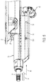
- FIG. 5 is a side view of the telescoping steering column similar in perspective to FIG. 4 , but illustrated in a collapsed state and with the mid jacket removed to show internal detail;
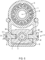
- FIG. 6 is another cross section of the telescoping steering column assembly illustrating a jacket deformation device of an energy absorbing assembly
- FIG. 7 is a partial side view of an upper jacket of the telescoping steering column assembly illustrating a rupture member of the jacket deformation device.
- a telescoping steering column 20 of the present disclosure may include an energy absorbing assembly 38 adapted to absorb energy in an axial direction.
- the telescoping steering column 20 is capable of selective adjustment and telescopic positioning, and may be capable of tilt-wise (i.e., rake) positioning. More specifically, the telescoping steering column 20 may be adapted to move axially between stowed and un-stowed states, and adjustably move axially between retracted and extended positions for user comfort and convenience.
- the telescoping steering column 20 is adapted to move axially between the retracted and extended positions when in the un-stowed state, and may move from the un-stowed state and toward the stowed state when in the fully retracted position.
- the telescoping steering column 20 is illustrated in the un-stowed state and in the extended position (i.e., nominal position).
- the telescopic positioning is generally for positioning a steering wheel (not shown) based on the comfort preferences of a driver (i.e., user) who has chosen to manually maneuver, or steer, the vehicle.
- a driver i.e., user
- the vehicle is maneuvering automatically (i.e., is in an autonomous mode).
- the steering wheel is generally out of the way (i.e., not within comfortable reach) of vehicle occupants.
- the telescoping steering column 20 may not include stowed and un-stowed states.
- the telescoping steering column 20 is attached to, and moves relative to, a vehicle structure 22 that may be, or may include, a bracket.
- vehicle structure 22 may be the undercarriage of a vehicle dash or console.
- the telescoping steering column 20 may include a steering shaft 24 , a plurality of jackets (i.e., three illustrated as 26 , 28 , 30 ), a plurality of adjustment mechanisms (i.e., three illustrated as 32 , 34 , 36 ), an energy absorbing assembly 38 , and a multitude of other components.
- the steering shaft 24 may be axially collapsible via a splined connection, or other means, generally known in the art.
- the shaft 24 may further include a distal end portion projecting in a rearward direction (see arrow 39 ) with respect to the vehicle for attachment to a steering wheel (not shown).
- the steering shaft 24 may be supported by the jacket 30 (e.g., upper jacket) for rotation about a rotation axis A, and is adapted to axially extend and retract with the upper jacket 30 .
- the upper jacket 30 may circumferentially extend continuously about the axis A and steering shaft 24 , longitudinally extends along the axis A, may generally be located radially outward from the steering shaft 24 , and may be tubular and/or extruded.
- the upper jacket 30 may be slideably supported by the jacket 28 (e.g., mid jacket) for telescopic motion along the rotation axis A, and between the extended and retracted positions.
- the mid jacket 28 may be disposed radially outward from the upper jacket 30 , may circumferentially extend continuously about the upper jacket 30 , and may be tubular and/or extruded. With respect to a vehicle, the mid jacket 28 may be substantially located forward of the upper jacket 30 when in the extended position.
- the mid jacket 28 may be slideably supported by the jacket 26 (e.g., lower jacket) for telescopic motion along the rotation axis A, and between the stowed and un-stowed states. That is, the lower jacket 26 has sufficient strength to support the jackets 28 , 30 and at least a portion of the steering shaft 24 .
- the lower jacket 26 may be generally located radially outward from the jacket 30 , may be extruded, and in one embodiment, may be substantially located above the mid jacket 28 . It is contemplated and understood that all three jackets 26 , 28 , 30 may be extruded (e.g., extruded aluminum), may be cylindrical, or may be a combination of both.
- the lower jacket 26 may be pivotally engaged to the vehicle structure 22 . More specifically, the lower jacket 26 is constructed and arranged to pivot about a pivot axis 40 that may be substantially normal to the rotation axis A. In one embodiment, the vehicle structure 22 and the pivot axis 40 may be disposed generally above the lower jacket 26 , thus the pivot axis 40 is spaced radially outward from the rotation axis A.
- the pivoting motion of the lower jacket 26 which at least in-part carries the jackets 28 , 30 , steering shaft 24 , and adjustment mechanisms 34 , 36 , may be a rake adjustment that may tilt (or raise and lower) a steering wheel for user convenience and comfort.
- the telescoping steering column 20 may further include at least one ball-and-track arrangement (i.e. two illustrated as 42 , 44 , see FIG. 2 ) adapted to reduce friction when the telescoping steering column 20 telescopically moves between states and positions.
- Ball-and-track arrangement 42 may be generally carried between, and supported by, the lower jacket 26 and the mid jacket 28 .
- Ball-and-track arrangement 44 may be generally carried between, and supported by, the mid jacket 28 and the upper jacket 30 .
- the ball-and-track arrangement 42 may include a plurality of balls, or bearings, 50 adapted to ride within an axially extending grove 52 having boundaries defined by the jackets 26 , 28 .
- the ball-and-track arrangement 44 may include a plurality of balls, or bearings, 46 adapted to ride within an axially extending grove 48 having boundaries defined by the jackets 28 , 30 .
- the extruded design of the jackets 26 , 28 , 30 along with the design characteristics of the ball-and-track arrangements 42 , 44 may optimize the telescoping steering column 20 stiffness and/or natural frequency response.
- the adjustment mechanism 32 may be a rake adjustment mechanism adapted to enable pivotal movement about pivot axis 40 , and between the lower jacket 26 and the vehicle structure, or bracket, 22 .
- the adjustment mechanism 32 may include an electric motor 54 and any variety of a gear drive 56 adapted to transform the rotational, mechanical, displacement of a motor shaft to a rake adjustment displacement.
- the adjustment mechanism 34 may be a stow adjustment mechanism adapted to telescopically move the mid jacket 28 with respect to the lower jacket 26 .
- the adjustment mechanism 34 may include an electric motor 58 , a leadscrew 60 , and a threaded nut 62 (i.e., shuttle).
- the leadscrew 60 extends along a rotation axis 64 , and may be threaded through the nut 62 .
- the electric motor 58 may be rigidly mounted and/or fixed to the jacket 26 , and is adapted to rotationally drive the leadscrew 60 about the axis 64 .
- the nut 62 may be engaged to the mid jacket 28 , and is adapted to threadably ride upon the leadscrew 60 when the leadscrew is rotated by the motor 58 .
- the adjustment mechanism 36 may be a user specific adjustment mechanism adapted to telescopically move the upper jacket 30 with respect to the mid jacket 28 .
- the adjustment mechanism 36 may include an electric motor 66 , a leadscrew 68 , and a threaded nut 70 (i.e., shuttle).
- the leadscrew 68 extends along a rotation axis 72 , and may be threaded through the nut 70 .
- the electric motor 66 may be rigidly mounted and/or fixed to the jacket 28 , and is adapted to rotationally drive the leadscrew 68 about the axis 72 .
- the nut 70 may be engaged to the upper jacket 30 , and is adapted to threadably ride upon the leadscrew 68 when the leadscrew is rotated by the motor 66 .
- the energy absorbing assembly 38 includes an energy absorbing strap 80 (see FIGS. 1 and 3 ), and a jacket deformation device 82 (see FIGS. 4-6 ).
- the energy absorbing strap 80 is carried between the lower jacket 26 and the mid jacket 28
- the jacket deformation device 82 is generally carried between the upper jacket 30 and a mid jacket assembly 83 that includes the mid jacket 28 and the adjustment mechanism 36 .
- the placement of the strap 80 and the device 82 is reversed.
- the energy absorbing assembly 38 does not include the energy absorbing strap 80 .
- the energy absorbing strap 80 is U-shaped and generally extends axially with respect to axis A. A first end of the strap 80 is fixed to the lower jacket 26 and an opposite second end is fixed to the mid jacket 28 .
- the energy absorbing strap 80 functions as is generally known by one skilled in the art.
- the jacket deformation device 82 includes at least one pin (i.e., two opposing pins 84 A, 84 B are illustrated) and at least one rupture member 86 (i.e., one rupture member associated with each pin 84 A, 84 B).
- the pins 84 A, 84 B may be fixed too, and project radially outward from, the nut 70 of the adjustment mechanism 36 of the mid jacket assembly 83 . More specifically, the pin 84 A projects radially outward in a first direction, and the pin 94 A projects radially outward in a substantially opposite second direction.
- the pins 84 A, 84 B are generally fixed to the mid jacket 28 as the jackets 28 , 30 move from a normal state (see FIG. 4 ) to a collapsed state (see FIG. 5 ).
- the pins 84 A, 84 B are generally illustrated as bolts that thread into respective bores 88 A, 88 B in the nut 70 . In another embodiment, the pins are clevis pins.
- the pin 84 A extends substantially radially outward from the nut 70 (i.e., or mid jacket 28 ), and through an opening 90 defined by the upper jacket 30 .
- the opening 90 may be a hole having a diameter (see arrow 92 in FIG. 7 ) that is substantially equal to, or slightly greater than, a diameter (see arrow 94 in FIG. 6 ) of the pin 84 A.
- the jacket deformation device 82 may include, or the pin 84 A is associated with, an opening 96 that may be an axially extending slot.
- the opening 96 may be disposed axially rearward of the opening 90 and with respect to the vehicle.
- the rupture member 86 is located axially between the openings 90 , 96 . More specifically, the rupture member 86 includes a rearward side 98 that defines, in-part, the opening 96 , and an opposite forward side 100 that defines, in-part, the opening 90 .
- the rupture member 86 is bridge-like and generally extends circumferentially with respect to the opening 90 , and includes opposite ends fixed to the upper jacket 30 .
- the rupture member 86 is an integral part of the upper jacket 30 with the openings 90 , 96 , and thus the rupture member 86 being machined into the jacket 30 .
- the rupture member 86 may be removably attached to the jacket 30 . It is contemplated and understood that the term “rupture” constitutes plastic deformation, or a breaking of the member 86 upon the application of a sufficient force F (see FIG. 5 ).
- the energy absorbing strap 80 is attached to, and carried between, the lower and mid jackets 26 , 28 , and the jacket deformation device 82 is carried between the upper jacket 30 and the mid jacket assembly 83 .
- the arrangement of the strap 80 and the device 82 may be generally reversed between jackets.
- Yet other embodiments may include one or both of the strap 80 and the device 82 being carried between the upper jacket 30 and the lower jacket 26 , and/or the mid jacket 28 and the lower jacket 26 .
- the energy absorbing assembly 38 may not include an energy absorbing strap.
- an axially directed force F may be exerted upon the steering wheel causing the energy absorption assembly 38 to actuate, moving from a normal state (see FIG. 4 ) to a collapsed state (see FIG. 5 ). More specifically, the energy absorbing strap 80 plastically deforms (not shown) as the mid jacket 28 telescopically moves in an axial forward direction (see arrow 85 in FIG. 4 ) and generally into the lower jacket 26 . Also upon application of force F, the rupture member 86 experiences an initial breakaway load causing the member 86 to break as the upper jacket 30 collapses axially into the mid jacket 28 .
- each slot 96 has a width (see arrow 102 in FIG. 7 ) that is less than the diameter 94 of the pins 84 A, 84 B, the upper jacket 30 undergoes plastic deformation as the pins 84 A, 84 B travel along the slots 96 (i.e., a running load).
- Advantages and benefits of the present disclosure include a telescoping steering column having greater telescope/stow distances than more traditional columns without increasing noise, vibration, and harshness concerns due to more traditional lengthy cantilever distances. Also, because single telescope/stow mechanisms are generally not applied, the column mounting locations may be more rearward in the vehicle thus enabling use of pre-existing, or more common, mounting points on a vehicle platform. Yet further, the three jacket design provides improved packaging when compared to a two jacket design.
Landscapes
- Engineering & Computer Science (AREA)
- Chemical & Material Sciences (AREA)
- Combustion & Propulsion (AREA)
- Transportation (AREA)
- Mechanical Engineering (AREA)
- Steering Controls (AREA)
Abstract
Description
Claims (16)
Priority Applications (1)
| Application Number | Priority Date | Filing Date | Title |
|---|---|---|---|
| US16/275,404 US11001292B2 (en) | 2018-04-02 | 2019-02-14 | Energy absorbing assembly of a telescoping steering column |
Applications Claiming Priority (2)
| Application Number | Priority Date | Filing Date | Title |
|---|---|---|---|
| US201862651455P | 2018-04-02 | 2018-04-02 | |
| US16/275,404 US11001292B2 (en) | 2018-04-02 | 2019-02-14 | Energy absorbing assembly of a telescoping steering column |
Publications (2)
| Publication Number | Publication Date |
|---|---|
| US20190300042A1 US20190300042A1 (en) | 2019-10-03 |
| US11001292B2 true US11001292B2 (en) | 2021-05-11 |
Family
ID=68057727
Family Applications (1)
| Application Number | Title | Priority Date | Filing Date |
|---|---|---|---|
| US16/275,404 Active 2039-08-09 US11001292B2 (en) | 2018-04-02 | 2019-02-14 | Energy absorbing assembly of a telescoping steering column |
Country Status (1)
| Country | Link |
|---|---|
| US (1) | US11001292B2 (en) |
Cited By (5)
| Publication number | Priority date | Publication date | Assignee | Title |
|---|---|---|---|---|
| US11554804B1 (en) * | 2021-08-19 | 2023-01-17 | Steering Solutions Ip Holding Corporation | Telescope drive bracket with anti-rotation features |
| US20230311972A1 (en) * | 2022-03-31 | 2023-10-05 | Steering Solutions Ip Holding Corporation | Externally translating, internally telescoping steering column assembly |
| US20230331283A1 (en) * | 2022-04-18 | 2023-10-19 | Steering Solutions Ip Holding Corporation | Externally translating, internally telescoping steering column assembly |
| US20240336294A1 (en) * | 2023-04-04 | 2024-10-10 | Hl Mando Corporation | Vehicle steering column |
| US12263880B2 (en) * | 2023-03-31 | 2025-04-01 | Hl Mando Corporation | Steering device of vehicle |
Families Citing this family (6)
| Publication number | Priority date | Publication date | Assignee | Title |
|---|---|---|---|---|
| US11383756B2 (en) * | 2019-11-06 | 2022-07-12 | Steering Solutions Ip Holding Corporation | System, method and apparatus translating and telescoping a steering column |
| US11738796B2 (en) * | 2020-07-28 | 2023-08-29 | Steering Solutions Ip Holding Corporation | Recirculating ball power steering system with sliding joint |
| CN115884912A (en) * | 2020-08-31 | 2023-03-31 | 日本精工株式会社 | steering column unit |
| CN112109796A (en) * | 2020-10-12 | 2020-12-22 | 坤泰车辆系统(常州)有限公司 | Steering column of automatic driving vehicle |
| DE102021003660A1 (en) | 2021-07-09 | 2023-01-12 | Schaeffler Technologies AG & Co. KG | Adjusting device for steering columns of vehicles |
| US12441387B1 (en) * | 2024-09-10 | 2025-10-14 | Steering Solutions Ip Holding Corporation | Rake adjustment assembly for vehicle steering system |
Citations (25)
| Publication number | Priority date | Publication date | Assignee | Title |
|---|---|---|---|---|
| US3945662A (en) * | 1971-05-25 | 1976-03-23 | Toyota Jidosha Kogyo Kabushiki Kaisha | Energy absorbing steering assembly |
| US4805478A (en) | 1987-06-26 | 1989-02-21 | General Motors Corporation | Steering column for vehicle with multitube energy absorbing mast jacket |
| US5476284A (en) * | 1991-09-11 | 1995-12-19 | Itt Corporation | Energy absorbing collapsible steering apparatus |
| GB2365826A (en) * | 2000-08-18 | 2002-02-27 | Yamada Seisakusho Kk | Collapsible tilting steering column |
| US20070068311A1 (en) * | 2005-09-08 | 2007-03-29 | Nsk Ltd. | Steering apparatus |
| US7641214B2 (en) * | 2006-05-11 | 2010-01-05 | Toyota Motor Engineering & Manufacturing North America, Inc. | Energy-absorbing trailer hitch receiver |
| US8627742B2 (en) * | 2008-04-04 | 2014-01-14 | Steering Solutions Ip Holding Corporation | Steering column assembly with shearable jacket connector |
| US8967017B2 (en) * | 2012-04-06 | 2015-03-03 | Yamada Manufacturing Co., Ltd. | Steering device |
| US8991865B2 (en) * | 2012-09-27 | 2015-03-31 | Mclaren Automotive Limited | Collapsible steering column |
| US20150251684A1 (en) * | 2012-09-05 | 2015-09-10 | Kayaba Industry Co., Ltd | Steering device |
| US9187116B2 (en) * | 2014-02-19 | 2015-11-17 | Yamada Manufacturing Co., Ltd. | Steering apparatus |
| US9399483B2 (en) * | 2013-11-20 | 2016-07-26 | Nsk Ltd. | Steering-bracket supporting apparatus and steering apparatus |
| US9421995B2 (en) * | 2013-10-30 | 2016-08-23 | Nsk Ltd. | Steering device |
| EP3124355A2 (en) * | 2015-07-31 | 2017-02-01 | Fujikiko Co., Ltd. | Steering column device |
| US9637161B2 (en) * | 2014-09-02 | 2017-05-02 | Nsk Ltd. | Steering device |
| US9789897B2 (en) * | 2015-08-11 | 2017-10-17 | Yamada Manufacturing Co., Ltd. | Steering apparatus |
| US20180057037A1 (en) * | 2016-08-31 | 2018-03-01 | Yamada Manufacturing Co., Ltd. | Steering device |
| DE102018201216A1 (en) * | 2017-01-26 | 2018-07-26 | Mando Corporation | steering column |
| US10160475B2 (en) * | 2016-03-25 | 2018-12-25 | Fuji Kiko Co., Ltd. | Steering column device |
| US10377408B2 (en) * | 2014-09-22 | 2019-08-13 | Nsk Americas, Inc. | Energy absorption module for vehicle steering column assembly |
| US20190283793A1 (en) * | 2018-03-16 | 2019-09-19 | Fuji Kiko Co., Ltd. | Steering column device |
| US10464590B2 (en) * | 2016-10-07 | 2019-11-05 | Steering Solutions Ip Holding Corporation | Steering column energy absorbing system |
| US20200031382A1 (en) * | 2016-09-27 | 2020-01-30 | Nsk Americas, Inc. | Steering assembly with positive lock and energy absorption and pyrotechnic actuator |
| US20200172148A1 (en) * | 2017-08-09 | 2020-06-04 | Thyssenkrupp Presta Ag | Steering column for a motor vehicle |
| US10683029B2 (en) * | 2017-01-26 | 2020-06-16 | Mando Corporation | Steering column |
-
2019
- 2019-02-14 US US16/275,404 patent/US11001292B2/en active Active
Patent Citations (26)
| Publication number | Priority date | Publication date | Assignee | Title |
|---|---|---|---|---|
| US3945662A (en) * | 1971-05-25 | 1976-03-23 | Toyota Jidosha Kogyo Kabushiki Kaisha | Energy absorbing steering assembly |
| US4805478A (en) | 1987-06-26 | 1989-02-21 | General Motors Corporation | Steering column for vehicle with multitube energy absorbing mast jacket |
| US5476284A (en) * | 1991-09-11 | 1995-12-19 | Itt Corporation | Energy absorbing collapsible steering apparatus |
| GB2365826A (en) * | 2000-08-18 | 2002-02-27 | Yamada Seisakusho Kk | Collapsible tilting steering column |
| US20070068311A1 (en) * | 2005-09-08 | 2007-03-29 | Nsk Ltd. | Steering apparatus |
| US7641214B2 (en) * | 2006-05-11 | 2010-01-05 | Toyota Motor Engineering & Manufacturing North America, Inc. | Energy-absorbing trailer hitch receiver |
| US8627742B2 (en) * | 2008-04-04 | 2014-01-14 | Steering Solutions Ip Holding Corporation | Steering column assembly with shearable jacket connector |
| US8967017B2 (en) * | 2012-04-06 | 2015-03-03 | Yamada Manufacturing Co., Ltd. | Steering device |
| US20150251684A1 (en) * | 2012-09-05 | 2015-09-10 | Kayaba Industry Co., Ltd | Steering device |
| US8991865B2 (en) * | 2012-09-27 | 2015-03-31 | Mclaren Automotive Limited | Collapsible steering column |
| US9421995B2 (en) * | 2013-10-30 | 2016-08-23 | Nsk Ltd. | Steering device |
| US9399483B2 (en) * | 2013-11-20 | 2016-07-26 | Nsk Ltd. | Steering-bracket supporting apparatus and steering apparatus |
| US9187116B2 (en) * | 2014-02-19 | 2015-11-17 | Yamada Manufacturing Co., Ltd. | Steering apparatus |
| US9637161B2 (en) * | 2014-09-02 | 2017-05-02 | Nsk Ltd. | Steering device |
| US10377408B2 (en) * | 2014-09-22 | 2019-08-13 | Nsk Americas, Inc. | Energy absorption module for vehicle steering column assembly |
| EP3124355A2 (en) * | 2015-07-31 | 2017-02-01 | Fujikiko Co., Ltd. | Steering column device |
| US9789897B2 (en) * | 2015-08-11 | 2017-10-17 | Yamada Manufacturing Co., Ltd. | Steering apparatus |
| US10160475B2 (en) * | 2016-03-25 | 2018-12-25 | Fuji Kiko Co., Ltd. | Steering column device |
| US20180057037A1 (en) * | 2016-08-31 | 2018-03-01 | Yamada Manufacturing Co., Ltd. | Steering device |
| US20200031382A1 (en) * | 2016-09-27 | 2020-01-30 | Nsk Americas, Inc. | Steering assembly with positive lock and energy absorption and pyrotechnic actuator |
| US10464590B2 (en) * | 2016-10-07 | 2019-11-05 | Steering Solutions Ip Holding Corporation | Steering column energy absorbing system |
| DE102018201216A1 (en) * | 2017-01-26 | 2018-07-26 | Mando Corporation | steering column |
| US10683029B2 (en) * | 2017-01-26 | 2020-06-16 | Mando Corporation | Steering column |
| US20200172148A1 (en) * | 2017-08-09 | 2020-06-04 | Thyssenkrupp Presta Ag | Steering column for a motor vehicle |
| JP2019156334A (en) * | 2018-03-16 | 2019-09-19 | 富士機工株式会社 | Steering column device |
| US20190283793A1 (en) * | 2018-03-16 | 2019-09-19 | Fuji Kiko Co., Ltd. | Steering column device |
Cited By (8)
| Publication number | Priority date | Publication date | Assignee | Title |
|---|---|---|---|---|
| US11554804B1 (en) * | 2021-08-19 | 2023-01-17 | Steering Solutions Ip Holding Corporation | Telescope drive bracket with anti-rotation features |
| US20230311972A1 (en) * | 2022-03-31 | 2023-10-05 | Steering Solutions Ip Holding Corporation | Externally translating, internally telescoping steering column assembly |
| US12570352B2 (en) * | 2022-03-31 | 2026-03-10 | Steering Solutions Ip Holding Corporation | Externally translating, internally telescoping steering column assembly |
| US20230331283A1 (en) * | 2022-04-18 | 2023-10-19 | Steering Solutions Ip Holding Corporation | Externally translating, internally telescoping steering column assembly |
| US12503151B2 (en) * | 2022-04-18 | 2025-12-23 | Steering Solutions Ip Holding Corporation | Externally translating, internally telescoping steering column assembly |
| US12263880B2 (en) * | 2023-03-31 | 2025-04-01 | Hl Mando Corporation | Steering device of vehicle |
| US20240336294A1 (en) * | 2023-04-04 | 2024-10-10 | Hl Mando Corporation | Vehicle steering column |
| US12454302B2 (en) * | 2023-04-04 | 2025-10-28 | Hl Mando Corporation | Vehicle steering column |
Also Published As
| Publication number | Publication date |
|---|---|
| US20190300042A1 (en) | 2019-10-03 |
Similar Documents
| Publication | Publication Date | Title |
|---|---|---|
| US11001292B2 (en) | Energy absorbing assembly of a telescoping steering column | |
| US10882548B2 (en) | Stowable steering column apparatus | |
| US10640139B2 (en) | Telescoping steering column | |
| US11866087B2 (en) | Steering column assembly for a vehicle | |
| US6264239B1 (en) | Steering column arrangement for a motor vehicle | |
| JP5765439B2 (en) | Steering device | |
| US20110239809A1 (en) | Length-adjustable steering actuation unit for a motor vehicle with a support and a steering column | |
| CN116902057B (en) | Steering column assembly with external translation and internal telescoping | |
| JP2008087582A (en) | Electric telescopic adjustment type steering device | |
| US11866088B2 (en) | Steering column assembly for a vehicle | |
| US11673599B2 (en) | Axially adjustable steering column assembly | |
| GB2587386A (en) | Steering column assembly for a vehicle | |
| CN118529119A (en) | Translating steering column with reduced packaging space | |
| US12570352B2 (en) | Externally translating, internally telescoping steering column assembly | |
| JP2008006953A (en) | Shock absorber for steering device with electric position adjustment mechanism | |
| US12227224B2 (en) | Externally translating, internally telescoping steering column assembly | |
| JP4507974B2 (en) | Steering device | |
| US11713067B1 (en) | Axially adjustable telescoping steering shaft assembly | |
| US12606231B1 (en) | Collapsible steering column assembly with releasably attached spring | |
| JP2006347219A (en) | Steering column device | |
| US11767051B2 (en) | Steering column for automotive | |
| KR20250051370A (en) | Stowable electric column | |
| KR20150017629A (en) | Steering column for vehicle | |
| JP2008080940A (en) | Electric telescopic adjustment type steering device |
Legal Events
| Date | Code | Title | Description |
|---|---|---|---|
| AS | Assignment |
Owner name: STEERING SOLUTIONS IP HOLDING CORPORATION, MICHIGA Free format text: ASSIGNMENT OF ASSIGNORS INTEREST;ASSIGNORS:DEROCHER, ROBERT C.;EDMUNDSON, LESLIE E.;REEL/FRAME:048329/0700 Effective date: 20190205 Owner name: STEERING SOLUTIONS IP HOLDING CORPORATION, MICHIGAN Free format text: ASSIGNMENT OF ASSIGNORS INTEREST;ASSIGNORS:DEROCHER, ROBERT C.;EDMUNDSON, LESLIE E.;REEL/FRAME:048329/0700 Effective date: 20190205 |
|
| FEPP | Fee payment procedure |
Free format text: ENTITY STATUS SET TO UNDISCOUNTED (ORIGINAL EVENT CODE: BIG.); ENTITY STATUS OF PATENT OWNER: LARGE ENTITY |
|
| STPP | Information on status: patent application and granting procedure in general |
Free format text: NOTICE OF ALLOWANCE MAILED -- APPLICATION RECEIVED IN OFFICE OF PUBLICATIONS |
|
| STPP | Information on status: patent application and granting procedure in general |
Free format text: PUBLICATIONS -- ISSUE FEE PAYMENT RECEIVED |
|
| STPP | Information on status: patent application and granting procedure in general |
Free format text: PUBLICATIONS -- ISSUE FEE PAYMENT VERIFIED |
|
| STCF | Information on status: patent grant |
Free format text: PATENTED CASE |
|
| MAFP | Maintenance fee payment |
Free format text: PAYMENT OF MAINTENANCE FEE, 4TH YEAR, LARGE ENTITY (ORIGINAL EVENT CODE: M1551); ENTITY STATUS OF PATENT OWNER: LARGE ENTITY Year of fee payment: 4 |