WO2022009495A1 - 作業工具及び電動工具 - Google Patents
作業工具及び電動工具 Download PDFInfo
- Publication number
- WO2022009495A1 WO2022009495A1 PCT/JP2021/015588 JP2021015588W WO2022009495A1 WO 2022009495 A1 WO2022009495 A1 WO 2022009495A1 JP 2021015588 W JP2021015588 W JP 2021015588W WO 2022009495 A1 WO2022009495 A1 WO 2022009495A1
- Authority
- WO
- WIPO (PCT)
- Prior art keywords
- operating member
- housing
- work tool
- switch
- motor
- Prior art date
Links
Images


Classifications
-
- B—PERFORMING OPERATIONS; TRANSPORTING
- B25—HAND TOOLS; PORTABLE POWER-DRIVEN TOOLS; MANIPULATORS
- B25F—COMBINATION OR MULTI-PURPOSE TOOLS NOT OTHERWISE PROVIDED FOR; DETAILS OR COMPONENTS OF PORTABLE POWER-DRIVEN TOOLS NOT PARTICULARLY RELATED TO THE OPERATIONS PERFORMED AND NOT OTHERWISE PROVIDED FOR
- B25F5/00—Details or components of portable power-driven tools not particularly related to the operations performed and not otherwise provided for
- B25F5/02—Construction of casings, bodies or handles
-
- B—PERFORMING OPERATIONS; TRANSPORTING
- B24—GRINDING; POLISHING
- B24B—MACHINES, DEVICES, OR PROCESSES FOR GRINDING OR POLISHING; DRESSING OR CONDITIONING OF ABRADING SURFACES; FEEDING OF GRINDING, POLISHING, OR LAPPING AGENTS
- B24B23/00—Portable grinding machines, e.g. hand-guided; Accessories therefor
- B24B23/02—Portable grinding machines, e.g. hand-guided; Accessories therefor with rotating grinding tools; Accessories therefor
- B24B23/028—Angle tools
Definitions
- the present invention relates to a tool in which a motor is driven or stopped according to an operation of an operating member.
- the hand-held work tool that performs work using the driving force of the motor is provided with a user interface for the user to turn on / off the operation of the motor.
- a user interface for the user to turn on / off the operation of the motor.
- an operation member that is gripped and operated by a user is known.
- the driving of the motor is started, and when the operating member is returned from the starting position to the initial position, the driving of the motor is stopped.
- the operating member extends long along the lower surfaces of both the motor housing accommodating the motor and the rear cover located behind the motor housing. It is provided in. This operating member extends from approximately half of the rear side of the motor housing to near the rear end of the rear cover. This operating member is urged toward the initial position by the urging member.
- the operating member pivots with the front end portion (that is, the end portion on the motor housing side) of the operating member as a fulcrum against the urging force of the urging member.
- this displacement of the operating member is detected by the switch, the motor is driven, and the tip tool is rotated by the rotational driving force of the motor.
- the grinding machine described in Patent Document 1 leaves room for improving the operability of the operating member.
- the operating member can be operated satisfactorily, but when the user wants to grip a place close to the tip tool, the operability deteriorates.
- the distance between the fulcrum and the gripping position becomes small when the user grips the rear half of the motor housing. Therefore, the stroke amount of the operating member at the grip position becomes small, and the user's feeling of operation is reduced.
- the switch since the switch is switched between the on state and the off state with a small stroke amount, it is difficult for the user to obtain the feeling of switching the on / off state. Moreover, if the stroke amount of the operating member is too small, the switch is unintentionally switched to the off state even if the user slightly loosens the force for gripping the operating member. Therefore, the user needs to grip the operating member more firmly. Further, when it is desired to grip the front side of the motor housing, the operation member cannot be operated because the finger does not reach it.
- the above problem is not limited to the grinding machine of Reference 1, but includes an operating member that extends in the longitudinal direction along the housing and is configured to be pivotal around the pivot axis by being gripped by the user. Common to any work tool.
- This specification discloses work tools.
- This work tool extends in the longitudinal direction of the work tool along the motor, housing, and housing, and is configured to be pivotal around the pivot axis by being gripped by the user, with respect to the pivot axis.
- An operating member exposed from the housing on both the first side and the second side opposite to the first side with respect to the pivot axis, and the operating member pivoting in the first direction to the first starting position.
- a switch configured to detect that it has been moved and to detect that the operating member has been pivoted to the second activation position in the second direction opposite to the first direction.
- the work tool is configured to drive the motor when the switch detects that the operating member has been pivoted to the first starting position, and the operating member is pivoted to the second starting position.
- the motor may be configured to be driven when it is detected by the switch.
- the operating member is exposed from the housing on both the first side with respect to the pivot axis and the second side with respect to the pivot axis (ie, user-grip-operable placement). Therefore, it is possible to secure a certain distance between both ends of the operating member sandwiching the pivot axis and the pivot axis of the operating member. Therefore, the stroke amount of the operating member at the gripping position is secured to some extent in both the case where the user grips and operates the first side of the operating member and the case where the user grips and operates the second side of the operating member. can. Therefore, the operability of the operating member is improved.
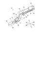
- FIG. It is a partially enlarged view of FIG. It is a partially enlarged view of FIG. It is an exploded view of the grinder and shows the state where the left housing is removed. It is an exploded view of a grinding machine, and shows the state where the left housing and the operation member are removed.
- FIG. 18 is a partially enlarged view. It is a partially enlarged view of FIG.
- a "housing" can be defined as a portion that houses any one or more components selected from the various components of a work tool.
- the operating member may be a single member.
- the operating member may include a first operating member arranged on the first side and a second operating member arranged on the second side.
- the first operating member and the second operating member may have a single pivot axis in common.
- the first operating member may have a first pivot axis and the second operating member may have a second pivot axis.
- the first operating member may be configured to be pivotable around the first pivot axis
- the second operating member may be configured to be pivotable around the second pivot axis. ..
- the first operating member is exposed from the housing on the first side with respect to the first pivot axis and the second pivot axis
- the second operating member is the first pivot axis and the second. It may be exposed from the housing on the second side opposite to the first side with respect to the pivotal axis of.
- the first side may be one side with respect to the pivot axis in the longitudinal direction.
- the second side may be opposite to the first side with respect to the pivot axis in the longitudinal direction.
- the first side may be one side with respect to the pivot axis in the crossing direction intersecting the longitudinal direction.
- the second side may be opposite to the first side with respect to the pivot axis in the crossing direction.
- the switch has a first switch configured to detect that the operating member has been pivoted to a first activation position, and an operating member up to a second activation position. It may include a second switch configured to detect that it has been pivoted. According to this configuration, it is possible to switch the on state / off state of the first switch and the second switch by directly utilizing the pivotal motion of the operating member. In other words, there is no need for a transmission mechanism to transmit the displacement of the operating member to the switch. Therefore, the device configuration can be simplified.
- the first switch may be located on the first side.
- the second switch may be located on the second side. According to this configuration, since it is not necessary to consolidate the first switch and the second switch on one side with respect to the pivot axis, it is easy to set the layout of the work tool that can suppress the increase in size.
- the operating member may include a hinge component that constitutes a portion of the hinge for the operating member to pivot. According to this configuration, the operating member can be held in a predetermined position and can be smoothly pivoted with a simple configuration.
- the hinge component may be a shaft portion that extends in the direction in which the pivot axis extends.
- the shaft portion may be rotatably supported within a boss formed in the housing. According to this configuration, if the housing is divided into half and the like, it is easy to assemble the work tool.
- the hinge component may be a boss portion that surrounds the shaft portion provided in the housing so that the pivot axis extends in the extending direction.
- the operating member may be a single member. According to this configuration, the number of parts is reduced, and a simple device configuration can be obtained. In addition, the operation method becomes easy for the user to understand.
- the work tool has a blocking position that prevents the operating member from being displaced to the first starting position and the operating member from being displaced to the second starting position, and the operating member.
- a lock-off member configured to be displaceable between a permissible position that allows displacement to the first start position and the operating member to be displaced to the second start position may be provided. According to this configuration, it is possible to prevent the motor from being driven against the intention of the user by inadvertently touching the operating member.
- the lockoff member may include a first lockoff member and a second lockoff member.
- the first lock-off member may be configured to pivot integrally with the operating member or may be located on the first side and engage with the housing thereby causing the operating member to be the first. Displacement between a first blocking position that prevents displacement to the starting position and a first permissible position that does not engage the housing and thereby allows the operating member to be displaced to the first starting position. It may be possible.
- the second lock-off member may be configured to pivot integrally with the operating member or may be located on the second side and engage with the housing thereby causing the operating member to be second.
- the lock-off function can be provided with a simple configuration.
- the work tool may include a tip tool configured to be driven by a motor.
- the housing comprises a motor housing that houses the motor and a user-gripable handle housing that is adjacent to the motor housing on the opposite side of the tip tool in the longitudinal direction and extends longitudinally. You may.
- the operating member may include a first portion extending longitudinally along the motor housing and a second portion extending longitudinally along the handle housing.
- the outer peripheral length of the handle housing around the longitudinal direction may be smaller than the outer peripheral length of the motor housing around the longitudinal direction.
- the operating member extends in a direction intersecting the longitudinal direction so as to follow the difference between the outer peripheral length of the handle housing and the outer peripheral length of the motor housing, and has a connecting portion for connecting the first portion and the second portion. You may be prepared.
- the pivot axis may be located at the connecting portion. According to this configuration, since the outer peripheral length of the handle housing and the second portion is relatively small, the user can easily perform the operation of gripping the second portion while gripping the handle housing.
- the user since the user usually does not grasp the boundary between the motor housing and the handle housing (that is, the part of the housing where the outer peripheral length changes), the user according to the present embodiment in which the pivot axis is located at the connecting portion.
- a large distance is secured between the pivot axis and the place where the user grips and operates the operating member in the longitudinal direction. Can be done. Therefore, a large stroke amount of the operating member at the grip position can be secured. That is, good operability of the operating member can be obtained in both the case where the user grips the motor housing and the case where the user grips the handle housing.
- the housing may have an annular portion.
- the operating member may have a ring shape along the inside of the annular portion.
- the pivot axis may be located at the longitudinal end of the operating member. According to this configuration, the number of parts is reduced, and a simple device configuration can be obtained.
- At least one of the first switch and the second switch is the first side end and the second side end of the operating member when the operating member is pivoted. It may be arranged at a position where it is pressed by any of the portions. According to this aspect, the distance between the position where at least one of the first switch and the second switch of the operating member is pressed and the pivot axis is increased. The amount of displacement of the operating member due to the pivot increases as the distance from the pivot axis increases. Therefore, according to this configuration, the amount of displacement required for the operating member to press at least one of the first switch and the second switch to turn on can be increased. Therefore, malfunctions of at least one of the first switch and the second switch are unlikely to occur. Alternatively, the dimensions of the work tool or the required accuracy of assembly can be reduced.
- the power tool houses a motor, a power transmission mechanism connected to the motor, a motor housing that houses the motor, a user-gripable handle housing, and a power transmission mechanism. It may include a gear housing, a tip tool holding portion connected to a power transmission mechanism, and an operating member.
- the operating member extends in the longitudinal direction of the work tool along the motor housing and the handle housing, has a rotation center, and is configured to be rotatable around the rotation center by being gripped by the user. You may.
- the handle housing may have a smaller diameter than the motor housing, and may include a connecting portion for connecting the handle housing and the motor housing.
- the power tool may be configured such that the center of rotation is provided at the connecting portion.
- this power tool allows the user to grip the handle housing and the user to grip the motor housing in the longitudinal direction.
- this power tool allows the user to grip the handle housing and the user to grip the motor housing in the longitudinal direction.
- the handle housing may be eccentric upward with respect to the motor housing.
- the center of rotation may be provided at the bottom of the connecting portion. According to this configuration, it is easy to grip the operating member.
- the operating member may include a first portion and a second portion.
- the first portion has a first end located on the first side with respect to the center of rotation in the longitudinal direction and may extend longitudinally along the motor housing.
- the second portion has a second end located on the second side opposite to the first side in the longitudinal direction with respect to the center of rotation and extends longitudinally along the handle housing. May be good.
- the first portion may have a shape in which the amount of protrusion of the first portion from the motor housing is maximized at the first end portion.
- the second portion may have a shape in which the amount of protrusion of the second portion from the handle housing is maximized at the second end.
- the direction of is closer to the horizontal direction. Therefore, the operation feeling of the user in the state where the operation member is grasped is improved. That is, the user can easily maintain the state of holding the operating member, that is, the state of driving the motor.
- a hand-held electric disc grinding machine (hereinafter, simply referred to as a grinding machine) will be exemplified as a work tool.
- a hand-held electric disc grinding machine (hereinafter, simply referred to as a grinding machine) is exemplified as a work tool including a housing, a motor, and an operating member.
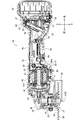
- the grinder 10 is configured to rotationally drive a substantially disk-shaped tip tool 38 mounted on the spindle 35.
- the spindle 35 is rotated by the rotational driving force provided by the electric motor 41.
- a grindstone, a rubber pad, a brush, a blade, and the like are prepared.
- the user selects an appropriate tip tool 38 according to the desired machining operation and attaches it to the grinder 10.
- processing work such as grinding, polishing, and cutting can be performed on the work piece according to the type of the tip tool 38.
- the direction in which the rotation axis AX1 (in other words, the motor shaft 42) of the electric motor 41 extends is defined as the front-rear direction of the grinder 10.
- the side where the tip tool 38 is located is defined as the front side, and the opposite side is defined as the rear side.
- the anteroposterior direction of the grinder 10 can also be defined as the longitudinal direction of the grinder 10.
- the direction in which the rotation axis AX2 of the spindle 35 (in other words, the rotation axis of the tip tool 38) extends is defined as the vertical direction of the grinder 10. In the vertical direction, the side where the tip tool 38 is located is defined as the lower side, and the opposite side is defined as the upper side.
- the directions orthogonal to the vertical direction and the front-back direction are defined as the left-right direction of the grinder 10.
- the right side when the front side is viewed from the rear side is defined as the right side of the grinder 10
- the opposite side is defined as the left side of the grinder 10.
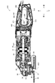
- the grinder 10 includes a housing 15.
- the housing 15 includes a metal gear housing 30 and a resin main body housing 20.
- a power transmission mechanism for transmitting the rotational driving force of the electric motor 41 to the tip tool 38 is housed in the gear housing 30.
- a small bevel gear 33, a large bevel gear 34, and a spindle 35 are housed in the gear housing 30 as a power transmission mechanism.
- the small bevel gear 33 is fixed around the motor shaft 42 at the front end of the motor shaft 42 of the electric motor 41.
- the spindle 35 is rotatably supported around the rotation axis AX2 by bearings arranged apart from each other in the vertical direction.
- the rotation axis AX2 intersects (more specifically, orthogonally) with the rotation axis AX1 of the electric motor 41.
- the large bevel gear 34 is fixed around the spindle 35 on the upper side of the spindle 35 and meshes with the small bevel gear 33.
- a resin or metal bearing box 32 that supports a bearing that rotatably supports the spindle 35 is attached to the lower portion of the gear housing 30.
- the bearing box 32 has a cylindrical shape extending in the vertical direction, and a cover 39 is detachably attached to the outer periphery thereof. The cover 39 covers the rear half of the tip tool 38.
- the spindle 35 extends vertically in the gear housing 30 and extends from the gear housing 30 on the lower side.
- a tip tool holding portion having an inner flange 36 and a locknut 37 is connected to the spindle 35.
- an inner flange 36 is attached around the spindle 35 at the lower end of the spindle 35 extending from the gear housing 30.
- a male threaded portion is formed below the inner flange 36 of the spindle 35, and a locknut 37 is attached to the male threaded portion.
- the main body housing 20 is arranged behind the gear housing 30.
- the body housing 20 is coupled to the gear housing 30 by a plurality of screws or bolts 24 (see FIGS. 1 and 2).
- the main body housing 20 is configured to be divisible in the left-right direction.
- a plurality of screw bosses 22 are formed on the right housing 20a and the left housing 20b, which are half-split bodies.
- the main body housing 20 is formed by connecting the right housing 20a and the left housing 20b to each other by a screw or a bolt 23 inserted into the screw boss 22.
- the main body housing 20 includes a motor housing 40, a handle housing 45, and a rear housing 46 (see FIG. 1).
- each of the right housing 20a and the left housing 20b is an integrally molded single member. However, at least a part of them may be formed by connecting a plurality of members.
- the motor housing 40 is adjacent to the gear housing 30 on the rear side of the gear housing 30.
- the motor housing 40 has a cylindrical shape extending in the front-rear direction.
- An electric motor 41 is housed in the motor housing 40.
- the electric motor 41 is driven by a direct current supplied from the battery 48 via the controller 49.
- the electric motor 41 may be driven by AC power supplied from an AC power source.
- the controller 49 controls the drive of the electric motor 41 by controlling the power supplied to the electric motor 41.
- the handle housing 45 is adjacent to the motor housing 40 on the rear side of the motor housing 40 (in other words, on the side opposite to the tip tool 38 in the longitudinal direction of the grinder 10).
- the handle housing 45 is a portion intended to be grasped by the user when using the grinder 10.
- the handle housing 45 has a cylindrical shape extending in the front-rear direction.
- the outer peripheral length of the handle housing 45 around the front-rear direction is substantially constant.
- the outer peripheral length (in other words, the diameter) of the handle housing 45 is smaller than the outer peripheral length (in other words, the diameter) of the motor housing 40 around the front-rear direction. Therefore, the user can easily grip the handle housing 45.
- the handle housing 45 may have an outer peripheral length equivalent to that of the motor housing 40.
- the upper end of the handle housing 45 is substantially the same as the upper end of the motor housing 40. That is, the handle housing 45 is eccentric upward with respect to the motor housing 40.
- the handle housing 45 is provided with a connecting portion 45a at its front end.
- the connecting portion 45a is a portion that connects the motor housing 40 and the handle housing 45.
- the connecting portion 45a has a diameter that gradually increases toward the front side.
- the rear housing 46 is adjacent to the handle housing 45 behind the handle housing 45.
- the rear housing 46 is a portion having a larger outer circumference around the front-rear direction than the handle housing 45.
- the controller 49 is housed in the rear housing 46.
- a battery mounting portion 47 to which the battery 48 can be attached and detached is provided at the rearmost part of the grinder 10.
- the controller 49 may be disposed within the handle housing 45.
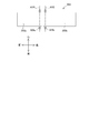
- FIGS. 1 and 3 below the motor housing 40 and the handle housing 45, there is an initial position for stopping the electric motor 41 and a starting position for starting the electric motor 41.
- An operation member 50 configured to be displaceable is provided. The operating member 50 extends in the anteroposterior direction along the body housing 20 (more specifically, along the motor housing 40 and the handle housing 45).
- the operation member 50 is a single member integrally molded, and includes a first portion 51, a second portion 52, and a connecting portion 53.
- the direction display in FIG. 4 indicates the direction when the operating member 50 is assembled to the grinder 10 and is in the initial position.
- the first portion 51 is a portion extending in the front-rear direction along the motor housing 40.
- the second portion 52 is a portion extending in the front-rear direction along the handle housing 45.
- the connecting portion 53 is a portion extending in a direction intersecting the front-rear direction and connecting the first portion 51 and the second portion 52.
- the connecting portion 53 extends so as to follow the difference between the outer peripheral length of the motor housing 40 and the outer peripheral length of the handle housing 45. That is, the connecting portion 53 extends from the rear end of the first portion 51 toward the front end of the second portion 52 so as to approach the rotation axis AX1 of the electric motor 41.
- the first portion 51, the second portion 52, and the connecting portion 53 are all exposed from the main body housing 20 on the lower side thereof (see FIG. 1).
- the connecting portion 53 is provided with two shaft portions 54.
- the two shaft portions 54 extend from the left side surface and the right side surface of the connecting portion 53 toward the outside in the left-right direction, respectively (in FIG. 4, only the shaft portion 54 extending from the left side surface is visible).
- Each of the shaft portions 54 is rotatably supported in a boss 21 (see FIG. 11) formed in the main body housing 20 so as to extend in the left-right direction at the position shown in FIG.
- the operating member 50 can be pivoted around the pivot axis AX3 (which is the central axis of the shaft portion 54 and extends in the left-right direction). That is, the shaft portion 54 functions as a part of the hinge for pivoting the operating member 50. If the pivot of the operating member 50 is realized in the form of a hinge, the operating member 50 can be held in a predetermined position and can be smoothly pivoted with a simple configuration.
- the operating member 50 includes a front end portion 55 and a rear end portion 56.
- An elongated hole 57 is formed in the vicinity of the base end (the end opposite to the front end portion 55) of the first portion 51 so as to penetrate the lower surface of the operating member 50 in the vertical direction.
- an elongated hole 58 is formed in the vicinity of the rear end portion 56 of the second portion 52 so as to penetrate the lower surface of the operating member 50 in the vertical direction.
- a first lock-off member 80 and a second lock-off member 90 extend downward from the elongated holes 57 and 58.
- the first lock-off member 80 is supported by the operating member 50 via a pin 83 extending between the left surface and the right surface of the first portion 51 of the operating member 50 while penetrating the first lock-off member 80. Has been done.
- the first lock-off member 80 is rotatable about the pin 83.
- the second lock-off member 90 is an operating member via a pin 93 extending between the left and right surfaces of the second portion 52 of the operating member 50 while penetrating the second lock-off member 90. Supported by 50.
- the second lock-off member 90 is rotatable about the pin 93. With this configuration, the first lock-off member 80 and the second lock-off member 90 are pivotally pivoted integrally with the operating member 50 when the operating member 50 is pivoted.
- the first lock-off member 80 is arranged on one side (specifically, the front side) in the longitudinal direction with respect to the pivot axis AX3, and the second lock-off member 90 is arranged with respect to the pivot axis AX3. It is arranged on the other side (specifically, the rear side) in the longitudinal direction.
- the operation member 50 includes a first end side region 59 and a second end side region 60.
- the first end side region 59 includes the front end portion 55 and is a region located on the opposite side of the pivot axis AX3 with respect to the first lockoff member 80 in the front-rear direction.
- the second end side region 60 is a region including the rear end portion 56 and located on the side opposite to the pivot axis AX3 with respect to the second lockoff member 90 in the front-rear direction.
- the operating member 50 further includes spring seats 62 and 64.
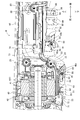
- the spring seat 62 is located on the front side of the shaft portion 54 in the longitudinal direction (more specifically, between the first lock-off member 80 and the front end portion 55 of the operating member 50).
- the spring seat 64 is located on the rear side of the shaft portion 54 in the longitudinal direction (more specifically, between the second lockoff member 90 and the rear end portion 56 of the operating member 50).
- a spring 63 is arranged around the spring seat 62, and a spring 65 is arranged around the spring seat 64.
- the spring 63 is arranged between the lower surface of the motor housing 40 and the upper surface of the first portion 51 of the operating member 50, and urges the first portion 51 downward.
- the spring 63 urges the operating member 50 in a direction in which the operating member 50 pivots counterclockwise.
- the spring 65 is arranged between the lower surface of the handle housing 45 and the upper surface of the second portion 52 of the operating member 50, and urges the second portion 52 downward. In other words, the spring 65 urges the operating member 50 in a direction in which the operating member 50 is pivoted clockwise.
- the operation member 50 at the initial position can be pivoted clockwise around the pivot axis AX3 by grasping and operating the first portion 51 extending along the motor housing 40, and the handle housing 45. If the user grips and operates the second portion 52 extending along the axis, it can be pivoted counterclockwise around the pivot axis AX3 (in other words, the center of rotation).
- the operation member 50 is provided with the above-mentioned operation member 50.
- the first lock-off member 80 and the second lock-off member 90 are attached.
- the first lock-off member 80 has a first blocking position (see FIG. 7) that prevents the operating member 50 from pivoting clockwise, and a first lock-off member that allows the operating member 50 to pivot clockwise. It is displaceable between the permissible position of 1 (see FIG. 8).
- the first lock-off member 80 includes an operating portion 81 and an engaging portion 82.
- the operation unit 81 projects below the first portion 51 at the first blocking position shown in FIG. 7.
- the engaging portion 82 extends upward on the rear side of the first lockoff member 80.
- a torsion spring 84 is wound around a pin 83 that supports the first lock-off member 80.
- One end of the torsion spring 84 is engaged with the first lock-off member 80, and the other end is engaged with the operating member 50.
- the torsion spring 84 urges the first lockoff member 80 toward the first blocking position shown in FIG. 7 (that is, in the clockwise direction).
- the operating member 50 moves the pivot axis AX3 (that is, the axis). It begins to move clockwise around the central axis of the portion 54).
- the engaging portion 82 of the first lock-off member 80 immediately abuts on the bottom surface 40a of the motor housing 40. Therefore, the operating member 50 can hardly move.
- the first lock-off member 80 has the torsion spring 84 as shown in FIG. It rotates counterclockwise by about 90 degrees against the urging force of, and is displaced to the first allowable position. With this displacement, the engaging portion 82 is oriented so as to extend forward.
- the engaging portion 82 does not abut on the bottom surface 40a, so that the operating member 50 is pivoted clockwise against the urging force of the spring 63. Can move.
- the second lock-off member 90 allows a second blocking position (see FIG. 7) to prevent the operating member 50 from pivoting counterclockwise and allowing the operating member 50 to pivot counterclockwise. It is displaceable between the second permissible position (see FIG. 9).
- the second lock-off member 90 includes an operation portion 91 and an engagement portion 92.
- the operation unit 91 projects below the second portion 52 at the second blocking position shown in FIG. 7.
- the engaging portion 92 extends upward on the rear side of the second lockoff member 90.
- a torsion spring 94 is wound around a pin 93 that supports the second lock-off member 90. One end of the torsion spring 94 is engaged with the second lock-off member 90, and the other end is engaged with the operating member 50. As a result, the torsion spring 94 urges the second lockoff member 90 toward the second blocking position shown in FIG. 7 (that is, in the clockwise direction).
- the operating member 50 moves the pivot axis AX3 (that is, the axis). It begins to move counterclockwise around the central axis of the portion 54).
- the engaging portion 92 of the second lock-off member 90 immediately abuts on the bottom surface 45b of the handle housing 45. Therefore, the operating member 50 can hardly move.
- the second lock-off member 90 has the torsion spring 94 as shown in FIG. It rotates about 90 degrees against the urging force of and is displaced to the second allowable position. With this displacement, the engaging portion 92 is oriented so as to extend forward.
- the engaging portion 92 does not abut on the bottom surface 45b, so that the operating member 50 counterclockwise against the urging force of the spring 65. Can be pivoted.
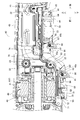
- the grinder 10 includes a first switch 71 and a second switch 73 in order to detect such a pivotal operation of the operating member 50.
- the first switch 71 and the second switch 73 are microswitches.
- the grinder 10 can be miniaturized.
- the pushing load required for switching from the off state to the on state is smaller than that of the switch used in the conventional grinding machine, so that the user can grip and operate the operation member 50 with a smaller force. Can be done.
- the operability of a conventional grinder in which the pivot axis is located at one end of the operating member and the distance between the other end of the operating member and the pivot axis is relatively large is not impaired.
- the first switch 71 and the second switch 73 may be of any other type (for example, a limit switch) capable of detecting the pivot of the operating member 50.
- the first switch 71 is arranged on the front side with respect to the shaft portion 54 (in other words, the pivot axis AX3), and the second switch 73 is arranged on the rear side with respect to the shaft portion 54. Is located in.
- the first switch 71 includes an actuator portion 72, and the actuator portion 72 is arranged at the bottom of the motor housing 40 so as to project downward.
- the second switch 73 includes an actuator portion 74, and is arranged at the bottom of the handle housing 45 so that the actuator portion 74 projects downward.
- the actuator portion 74 extends downward from a hole formed in the bottom surface 45b of the handle housing 45.
- the operating member 50 pivots clockwise around the pivot axis AX3 (that is, the central axis of the shaft portion 54). Then, when the pivot angle reaches a predetermined amount, the actuator portion 72 of the first switch 71 is pressed by the front end portion 55 of the operating member 50. As a result, the on / off state of the internal contact of the first switch 71 is switched, and the first switch 71 detects the clockwise pivot of the operating member 50.
- the first switch 71 is electrically connected to the controller 49.
- the controller 49 When the controller 49 detects that the clockwise rotation of the operating member 50 is detected by the first switch 71, the controller 49 supplies the electric power from the battery 48 to the electric motor 41, and the electric motor 41 To drive.
- the operating member 50 returns to the initial position by the urging force of the spring 63, and the first lock-off member 80 also pivots together with the operating member 50 and the torsion spring 84 is attached. The force returns to the first blocking position (see Figure 7).
- the controller 49 detects it, stops the supply of electric power to the electric motor 41, and stops the electric motor 41. ..
- the user displaces the second lock-off member 90 from the second blocking position to the second allowable position, and in that state, further grips the second portion 52 of the operating member 50. Then, the operating member 50 pivots counterclockwise around the pivot axis AX3 (that is, the central axis of the shaft portion 54). Then, when the pivot angle reaches a predetermined amount, the actuator portion 74 of the second switch 73 is pressed by the engaging portion 92 of the second lockoff member 90. Since the engaging portion 92 is formed in an arc shape at a portion in contact with the actuator portion 74, the actuator portion 74 can be smoothly pressed.
- the actuator unit 74 When the actuator unit 74 is pressed, the on / off state of the internal contact of the second switch 73 is switched, and the second switch 73 detects the counterclockwise pivot of the operating member 50.
- the second switch 73 is electrically connected to the controller 49.
- the controller 49 detects that the counterclockwise pivot of the operating member 50 is detected by the second switch 73, the controller 49 supplies the electric power from the battery 48 to the electric motor 41 to supply the electric motor. Drive 41.
- the rotation direction of the electric motor 41 at this time is the same as when the clockwise pivot of the operating member 50 is detected by the first switch 71.
- the operating member 50 When the user releases the finger from the operating member 50, the operating member 50 returns to the initial position by the urging force of the spring 65, and the second lock-off member 90 also pivots together with the operating member 50 and the torsion spring 94 is attached. The force returns to the second blocking position (see Figure 7).
- the controller 49 detects it, stops the supply of electric power to the electric motor 41, and stops the electric motor 41. ..
- the electric motor 41 also rotates in the same direction when the operating member 50 is pivoted counterclockwise by grasping and operating the second portion 52 on the rear side with respect to the driving axis AX3.
- the operating member 50 is exposed from the main body housing 20 both on the front side and the rear side with respect to the pivot axis AX3, and the user can use the first portion on the front side with respect to the pivot axis AX3.
- the gripping operation of the operating member 50 can be performed by using the 51 and the second portion 52 on the rear side with respect to the pivot axis AX3, whichever is desired. Since the first portion 51 extends in the front-rear direction along the motor housing 40 and the second portion 52 extends in the front-rear direction along the handle housing 45, the user can grip the motor housing 40. It is possible to grip and operate the operation member 50 both in the case of gripping and in the case of gripping the handle housing 45.
- pivot axis AX3 Since the pivot axis AX3 is located between the front end portion 55 and the rear end portion 56 of the operating member 50, the distance between the pivot axis AX3 and the front end (that is, the front end portion 55) of the first portion 51, and , Both the pivot axis AX3 and the rear end (that is, the rear end 56) of the second portion 52 can be secured to some extent. Therefore, in both the case where the user grips and operates the first portion 51 and the case where the user grips and operates the second portion 52 (in other words, when the user grips the motor housing 40).
- the distance between the grip position and the pivot axis AX3, and by extension, the stroke amount of the operating member 50 at the grip position can be secured to some extent. Therefore, the operability of the operating member 50 is improved. That is, good operability of the operating member 50 can be obtained in both the case where the user grips the motor housing 40 and the case where the user grips the handle housing 45. In other words, good operability of the operating member 50 can be obtained on both the front side and the rear side of the grinder 10.
- the first switch 71 is arranged on the front side with respect to the pivot axis AX3, and the second switch 73 is arranged on the rear side with respect to the pivot axis AX3.
- the switches are concentrated on one side of the pivot axis AX3, it is easier to set the layout of the grinder 10 that can suppress the increase in size.
- a single operating member 50 is configured to pivot clockwise or counterclockwise according to the grip position of the user. Therefore, as compared with the case where the same function is realized by using a plurality of operating members, the number of parts is reduced and the device configuration can be simplified. In addition, the operation method becomes easy for the user to understand.
- the pivot axis AX3 extends in a direction intersecting the front-rear direction of the operating member 50 and connects the first portion 51 and the second portion 52. (In other words, it is located at a place where the outer peripheral length around the front-back direction gradually changes).
- the rotation center of the operating member 50 is provided in the connecting portion 45a connecting the motor housing 40 and the handle housing 45.
- the user selectively grips the motor housing 40 or the handle housing 45 according to his / her preference and the type of work, but the vicinity of the boundary between the motor housing 40 and the handle housing 45 is different from other places. In comparison, it is less likely to be gripped by the user.
- the pivot axis AX3 center of rotation
- the distance between the grip position and the pivot axis AX3 that is, the stroke amount of the operating member 50 at the grip position
- a stroke amount that facilitates switch operation in both the first portion 51 and the second portion 52 (in other words, the amount of protrusion from the main body housing 20 in the rotation direction of the operating member 50). ) Is secured, so that the operation is easy in both the case of gripping the first portion 51 and the case of gripping the second portion 52. Further, since the pivot axis AX3 is arranged between the front end portion 55 and the rear end portion 56, the operation member 50 is prevented from being excessively projected from the product at the [0] grip position. An appropriate stroke amount of 50 can be secured.
- both the front side and the rear side of the operating member 50 are due to the position of the pivot axis AX3 between the front end portion 55 and the rear end portion 56.
- an appropriate amount of protrusion can be secured. That is, good operability can be obtained on both the front side and the rear side of the operation member 50.
- the pivot axis AX3 is arranged between the first portion 51 and the second portion 52, the pivot axis AX3 at the grip position is used for both the first portion 51 and the second portion 52.
- the distance can be secured appropriately, and the pushing load is not too large to be difficult to push.
- the pushing load is appropriately set for both the first portion 51 and the second portion 52.
- the first switch 71 is arranged so that the actuator portion 72 is pressed against the front end portion 55 of the operating member 50 when the operating member 50 is pivoted clockwise. Therefore, it is possible to secure a large distance between the portion of the operating member 50 that presses the actuator portion 72 and the pivot axis AX3.
- the amount of displacement of the operating member 50 due to pivoting increases as the distance from the pivoting axis AX3 increases. Therefore, the amount of displacement required for the operating member 50 to press the actuator portion 72 and the first switch 71 to be turned on can be increased. Therefore, a malfunction of the first switch 71 is unlikely to occur.
- the second switch 73 has the above embodiment in which the actuator portion 74 is pressed by the engaging portion 92 of the second lockoff member 90 when the operating member 50 is pivoted counterclockwise.
- the actuator portion 74 may be arranged at a position where it is pressed by the rear end portion 56 of the operating member 50 when the operating member 50 is pivoted counterclockwise.
- the second switch 73 is in a position where the actuator portion 74 is pressed by the engaging portion 92 of the second lockoff member 90 when the operating member 50 is pivoted counterclockwise. Have been placed.
- an external force acts on the operating member 50, and the engaging portion 92 of the second lock-off member 90 and the handle housing. Even if the operating member 50 bends with the contact point with the bottom surface 45b of the 45 as a fulcrum, it is possible to prevent the operating member 50 or a part of the second lockoff member 90 from unintentionally pressing the actuator portion 74.
- both the second switch 73 and the second lockoff member 90 may be arranged closer to the rear end portion 56 between the pivot axis AX3 and the rear end portion 56 in the front-rear direction.
- both the first switch 71 and the first lockoff member 80 may be located closer to the front end 55 between the pivot axis AX3 and the front end 55.
- the second switch 73 may be arranged closer to the second lock-off member 90 between the second lock-off member 90 and the rear end portion 56 in the front-rear direction.
- the first switch 71 may be arranged closer to the first lock-off member 80 between the first lock-off member 80 and the front end portion 55 in the front-rear direction.
- the second switch 73 is arranged at a position where it is pressed by the second lock-off member 90 when the operating member 50 is pivoted counterclockwise, the second lock-off member 90 is damaged. Even in this case, it is possible to prevent the electric motor 41 from operating unintentionally.
- the first switch 71 is located at a position pressed by the first lockoff member 80 when the operating member 50 is pivoted clockwise. You may.
- the first switch 71 and the first lockoff member 80 may be arranged in the front-rear direction between the pivot axis AX3 and the front end portion 55 closer to the front end portion 55. According to such an arrangement, the feature that the distance between the first switch 71 and the pivot axis AX3 is large and the feature that the distance between the first switch 71 and the first lock-off member 80 is small. It is compatible. Therefore, the effects of these features described above can be maximized. That is, the malfunction of the first switch 71 can be further suppressed, and the required accuracy of the dimensions or assembly of the grinder 10 can be further lowered.
- the second switch 73 and the second lockoff member 90 may be arranged between the pivot axis AX3 and the rear end 56 closer to the rear end 56.
- the feature that the distance between the second switch 73 and the pivot axis AX3 is large and the feature that the distance between the second switch 73 and the second lockoff member 90 is small are realized. It is compatible. Therefore, the effects of these features described above can be maximized.
- the operating member 50 may have a configuration that is easy to grip in the vicinity of the front end portion 55 or the rear end portion 56.
- the first lock-off member 80 may be arranged closer to the front end portion 55 between the front end portion 55 and the pivot axis AX3 in the front-rear direction
- the second lock-off member 80 may be arranged.
- the member 90 may be arranged closer to the rear end portion 56 between the pivot axis AX3 and the rear end portion 56 in the front-rear direction. Normally, the user grips and operates the operation member 50 with one of the fingers of one hand while rotating the first lock-off member 80 or the second lock-off member 90.
- the location is likely to be in the vicinity of the first lockoff member 80 or the second lockoff member 90.
- the first lock-off member 80 when the user grips and operates the first portion 51, for example, the first lock-off member 80 is rotated by the ring finger or the little finger, and the first end with the index finger and the middle finger. It is conceivable to grip and operate the part side region 59.
- the user grips and operates the second portion 52 when the user grips and operates the second portion 52, for example, the user rotates the second lock-off member 90 with the index finger and the second end with the middle finger and the ring finger. It is conceivable to grip and operate the part side region 60.
- the first lock-off member 80 is arranged closer to the front end portion 55 as described above, the user can easily grip and operate the vicinity of the front end portion 55, and the second lock-off member 90 can be operated as described above. If it is arranged closer to the rear end portion 56, the user can easily grasp the vicinity of the rear end portion 56. With such an arrangement, the distance between the pivot axis AX3 and the grip portion can be further secured. Therefore, according to the principle of the lever, the grip load of the user required to turn on the first switch 71 or the second switch 73 can be reduced, and the operability is improved.
- the first portion 51 located anterior to the pivot axis AX3 has a front end 55 with an amount of protrusion (ie, downward) of the first portion 51 from the motor housing 40. It may have a shape that maximizes at.
- the second portion 52 may have a shape in which the amount of protrusion of the second portion 52 from the handle housing 45 is maximized at the rear end portion 56.
- the first portion 51 has a shape in which the amount of protrusion of the first portion 51 from the motor housing 40 gradually increases toward the front (that is, as the distance from the pivot axis AX3 increases). May be.
- the second portion 52 has a shape in which the amount of protrusion of the second portion 52 from the handle housing 45 gradually increases toward the rear (that is, as the distance from the pivot axis AX3 increases). good.
- the orientation of the exposed portion of the operating member 50 when the user grips the operating member 50 is closer to the horizontal direction.
- the lower surface of the first portion 51 ie, the surface to be gripped by the user
- the lower surface of the second portion 52 may extend in the horizontal direction when the second switch 73 is in the ON state.
- the operating member 150 includes a third portion 155 behind the second portion 52.
- the third portion 155 extends upward from the rear end of the second portion 52, then bends and extends rearward, and is housed inside the main body housing 120.
- a first switch 171 is arranged above the third portion 155, and a second switch 173 is arranged below the third portion 155.
- the third portion 155 presses the first switch 171 and when the operating member 150 is pivoted clockwise, the third portion 155 presses. Press the second switch 173.
- the two switches may be centrally arranged on one side with respect to the pivot axis AX3 in the front-rear direction.
- the operation member 250 includes a first operation member 250a and a second operation member 250b.
- the first operating member 250a extends in the front-rear direction along the motor housing 40 (not shown in FIG. 13), and the second operating member 250b extends back and forth along the handle housing 45 (not shown in FIG. 13). It extends in the direction.
- the first operating member 250a is provided with a boss 255a at its rear end, and the second operating member 250b is provided with a boss 255b at its front end.
- the bosses 255a and 255b are hingedly connected to the shaft portion 225 formed in the main body housing 20.
- the first operating member 250a clockwise around the pivot axis AX3 (which is the central axis of the shaft portion 225 and extends in the left-right direction).
- the second operating member 250b is pivoted counterclockwise around the pivot axis AX3. In this way, two operating members 250a and 250b that can be pivoted in opposite directions about the common pivot axis AX3 may be used.
- the operation member 350 includes a first operation member 350a and a second operation member 350b.
- the first operating member 350a extends in the front-rear direction along the motor housing 40 (not shown in FIG. 14), and the second operating member 350b extends back and forth along the handle housing 45 (not shown in FIG. 14). It extends in the direction.
- the first operating member 350a is provided with a shaft portion 325a at its rear end, and the second operating member 350b is provided with a shaft portion 325b at its front end.
- the shaft portions 325a and 325b are pivotally supported in two bosses formed in the main body housing 20, respectively.
- the first operating member 350a When the user grips and operates the first operating member 350a, the first operating member 350a is centered on the first pivot axis AX4 (which is the central axis of the shaft portion 325a and extends in the left-right direction). It moves clockwise.
- the second operating member 350b holds the second pivot axis AX5 (this is the central axis of the shaft portion 325b and extends in the left-right direction). It moves counterclockwise as the center.
- two operating members 350a and 350b having separate pivot axes AX4 and AX5 may be used.
- the grinding machine 410 includes a handle housing 440 on the rear side of the motor housing 40.
- the handle housing 440 is a hollow member extending in a long shape in the front-rear direction.
- the handle housing 440 is a so-called loop type, and has an annular portion 441 extending in a long shape on the rear side thereof.
- the annular portion 441 is a portion intended to be gripped by the user.
- the annular portion 441 is a portion that surrounds the periphery of the through hole 442 that penetrates the handle housing 440 in the left-right direction, and has a closed ring shape.
- the through hole 442 has a shape in which the width in the vertical direction increases toward the front side when viewed in the left-right direction.
- the annular portion 441 may have an annular shape with an open trailing end.
- the operation member 450 is arranged inside the handle housing 440.
- the operating member 450 is loop-shaped and has a ring shape along the inside of the handle housing 440 (in other words, along the outer shell of the through hole 442).
- the operating member 450 extends in the front-rear direction as the longitudinal direction.
- the inner edge portion of the operating member 450 has a substantially oval shape when viewed in the left-right direction.
- the outer edge portion of the operating member 450 has a shape in which the width in the vertical direction increases toward the front side when viewed in the left-right direction.
- the operating member 450 is arranged so as to be entirely exposed from the handle housing 440 (more specifically, the annular portion 441).
- the clearance between the inner edge portion of the annular portion 441 of the handle housing 440 and the main body 451 of the operating member 50 increases toward the front side.
- the main body 451 may have a ring shape with its front end open.
- the operation member 450 includes the main body 451 having the above-mentioned ring shape and the pivot shaft portion 454.
- the pivot shaft portion 454 is arranged so as to project toward the rear side from the main body 451 at the rear end of the main body 451 and at the center in the vertical direction.
- the pivot shaft portion 454 has a cylindrical shape extending in the left-right direction, and a through hole 455 extending in the left-right direction is formed inside the cylindrical shaft portion 454.
- a pin 461 is inserted into the through hole 455 so as to extend in both the left and right directions from the pivot shaft portion 454.
- the pin 461 is supported between the left and right surfaces at the rear end of the annular portion 441, as shown in FIG.
- the operating member 450 is configured to be pivotable about the pin 461 (in other words, about the pivot axis AX3 shown in FIG. 16) as shown in FIGS. 19 and 20. ..
- the operating member 450 intersects in the front-rear direction (in other words, the longitudinal direction of the grinding machine 410) (in the present embodiment). In the vertical direction), it is exposed from the handle housing 440 on both sides (that is, upper and lower sides) with respect to the pivot axis AX3.
- the spring 462 is arranged in a compressed state.
- the spring 462 is arranged in a bottomed hole 456 formed in the upper portion so that horizontal movement is restricted.
- the spring 462 is arranged substantially in the center of the main body 451 in the front-rear direction. With this configuration, the spring 462 urges the operating member 450 downward.
- a spring 463 is arranged in a compressed state between the lower inner edge portion of the annular portion 441 and the portion extending in the front-rear direction on the lower side of the main body 451 (hereinafter, also referred to as a lower portion). Will be done.
- the spring 463 is arranged in a bottomed hole 457 formed in the lower portion so that horizontal movement is restricted.
- the spring 463 is arranged at the same position as the spring 462 in the front-rear direction. With this configuration, the spring 463 urges the operating member 450 upward.
- the operating member 450 is maintained in the vertical direction at the center of the through hole 442 of the annular portion 441. This position is the initial position of the operating member 450 when it is not gripped by the user.
- a protrusion 458 protruding upward is formed near the front end of the upper portion of the main body 451.
- a protrusion 459 protruding downward is formed near the front end of the lower portion of the main body 451.
- the protrusions 458 and 459 are in the same position in the front-rear direction.
- the protrusions 458 and 459 are provided to press the actuator portion 472 of the first switch 471 and the actuator portion 474 of the second switch 473, respectively, when the operating member 450 is pivoted.
- the first switch 471 is attached to the annular portion 441 above the pin 461 (the pivot axis AX3) so that the actuator portion 472 is exposed from the annular portion 441.
- the second switch 473 is attached to the annular portion 441 so that the actuator portion 474 is exposed from the annular portion 441 below the pin 461 (the pivot axis AX3).
- the first switch 471 and the actuator unit 472 are arranged at positions corresponding to the protrusions 458 and 459 of the operating member 450, that is, near the front end of the operating member 450.
- through holes 452 and 453 are formed on the front side of the main body 451.
- the through hole 452 penetrates the upper portion of the main body 451 in the vertical direction.
- the through hole 453 penetrates the lower portion of the main body 451 in the vertical direction.
- a first lock-off member 480 and a second lock-off member 490 are mounted in the through holes 452 and 453, respectively.
- first lock-off member 480 and the second lock-off member 490 have structures similar to those of the first lock-off member 80 and the second lock-off member 90 of the first embodiment, respectively, they have a structure similar to that of the first lock-off member 80 and the second lock-off member 90.
- first lock-off member 480 is attached to the main body 451 via a pin 483 supported by the main body 451.
- the first lock-off member 480 has a first blocking position (see FIG. 20) that prevents the operating member 450 from pivoting clockwise, and a first lock-off member that allows the operating member 450 to pivot clockwise. It is pivotable around pin 483 between the permissible position of 1 (see FIG. 19).
- the first lockoff member 480 is urged in the counterclockwise direction (in other words, toward the first blocking position) by the torsion spring 484.
- the operating portion 481 and the engaging portion 482 project from the lower surface and the upper surface of the upper portion of the main body 451 respectively.
- the second lock-off member 490 is attached to the main body 451 via a pin 493 supported by the main body 451.
- the second lock-off member 490 allows a second blocking position (see FIG. 19) to prevent the operating member 450 from pivoting counterclockwise and allowing the operating member 450 to pivot counterclockwise. It is pivotable around pin 493 between the second permissible position (see FIG. 20).
- the second lockoff member 490 is urged clockwise (in other words, towards the second blocking position) by the torsion spring 494.
- the operating portion 491 and the engaging portion 492 project from the upper surface and the lower surface of the lower portion of the main body 451, respectively.
- the user moves the operation unit 481 of the first lockoff member 480 from the first blocking position (see FIG. 20) to the first allowable position (see FIG. 19).
- the operating member 450 centers on the pin 461 against the urging force of the spring 462. As it moves clockwise. Then, when the operating member 450 is pivoted clockwise to the first starting position, the protrusion 458 of the operating member 450 pushes the actuator portion 472 of the first switch 471 upward and displaces it.
- the first switch 471 that detects this is switched from the off state to the on state, and the electric motor 41 is driven.
- the operating member 450 returns to the initial position by the urging force of the spring 462, and the first lock-off member 480 returns to the first blocking position by the urging force of the torsion spring 484.
- the user pivots the operation unit 491 of the second lockoff member 490 from the second blocking position (see FIG. 19) to the second allowable position (see FIG. 20).
- the operating member 450 counterclockwise around the pin 461 against the urging force of the spring 463. Move around.
- the protrusion 459 of the operating member 450 presses the actuator portion 474 of the second switch 473 downward to displace it.
- the second switch 473 that detects this is switched from the off state to the on state, and the electric motor 41 is driven.
- the rotation direction of the electric motor 41 at this time is the same as when the first switch 471 is turned on.
- the operating member 450 returns to the initial position by the urging force of the spring 463, and the second lock-off member 490 returns to the second blocking position by the urging force of the torsion spring 494.
- the same effect as that of the first embodiment can be obtained.
- the electric motor 41 can be driven by grasping and operating either the portion or the portion. Since the pivot axis AX3 is located between the upper portion and the lower portion, the distance between the pivot axis AX3 and the grip position of the upper portion of the main body 451 and the distance between the pivot axis AX3 and the main body 451 Both the grip position of the side part and the distance can be secured to some extent.
- the radius of gyration of the operating member 450 at the grip position, and by extension, the stroke amount can be secured to some extent. Therefore, good operability of the operating member 450 can be obtained.
- the pin 461 (the pivot axis AX3) is located at the rear end of the operating member 450, and the first switch 471 and the second switch 473 are the operating member 450. It is located at a position corresponding to the front end of the upper part and the lower part. Therefore, the pivot axis AX3 in the front-rear direction and the first switch 471 and the second switch 473 (in other words, the protrusions 458 and 459 that press the first switch 471 and the second switch 473). A large distance can be secured for each of the above. Therefore, the amount of displacement required for the operating member 450 to press the actuator portion 472 or 474 to turn on the first switch 471 or 473 can be increased. Therefore, malfunctions of the first switches 471 and 473 are unlikely to occur.
- the operating member 450 since the pin 461 (driven axis AX3) of the operating member 450 is located at the rear end of the operating member 450, the front side of the operating member 450 relatively far from the driving axis AX3 A greater stroke feeling can be obtained when the grip operation is performed than when the rear side is gripped.
- the first lock-off member 480 and the second lock-off member 490 are located on the front side of the operation member 450, the user grips and operates the front side of the operation member 450, that is, more The user can be guided so that a large stroke feeling can be obtained.
- the pivot axis AX3 may be located near the boundary between the motor housing 40 and the handle housing 45 instead of being located at the connecting portion 53.
- Located near the boundary means, for example, that the area between the end of the motor housing 40 on the opposite side of the handle housing 45 and the boundary is divided into three equal parts in the longitudinal direction to form three areas. It may be defined as being located within the region closest to the boundary when obtained.
- located near the boundary means, for example, that the area between the end of the handle housing 45 opposite to the motor housing 40 and the boundary is divided into three equal parts in the longitudinal direction. It may be defined as being located within the region closest to the boundary when the region is obtained.
- the pivot axis AX3 may be located in the middle region when the operating member 50 is divided into three equal parts in the longitudinal direction to obtain three regions.
- the operating member 50 may include a convex portion that protrudes downward instead of the hinge structure.
- the convex portion may be arranged on the bottom surface of the main body housing 20, and the operating member 50 may be pivoted with the convex portion as a fulcrum.
- the grinder 10 or 450 may include a transmission mechanism configured to transmit the displacement of the operating member 50 or 450 to a single switch.
- This transmission mechanism is configured to displace in conjunction with the clockwise pivot of the operating member 50 or 450 to press a single switch, and the counterclockwise pivot of the operating member 50 or 450. It is configured to displace in conjunction with and press a single switch.
- the transmission mechanism can be implemented by any known mechanical element, such as a link member.
- a single lock-off member engages the operating member 50 or 450 so that the operating member 50 or 450 cannot rotate both clockwise and counterclockwise, and the operating member 50 or 450 of the operating member 50 or 450.
- the blocking position that blocks the pivot and the permissible position that does not engage the operating member 50 or 450 and allows both clockwise and counterclockwise pivoting of the operating member 50 or 450. It may be configured to be displaceable.
- the pivot axis AX3 may be located at the front end of the operating member 450.
- the through hole 442 of the handle housing 440 may have a shape in which the width in the vertical direction increases toward the rear side when viewed in the left-right direction.
- the outer edge portion of the operating member 450 may have a shape in which the width in the vertical direction increases toward the rear side when viewed in the left-right direction.
- the clearance between the inner edge portion of the annular portion 441 of the handle housing 440 and the main body 451 of the operating member 50 may be increased toward the rear side.
- the above-described embodiment is applicable not only to grinders 10 and 410 but also to any work tool provided with a grip-operated operating member extending in a long shape along the housing.
- Torsion spring 120 ... Main body housing 150 ... Operation member 155. .. 3rd part 171 ... 1st switch 173 ... 2nd switch 225 ... Shaft part 250 ... Operating member 250a ... 1st operating member 250b ... 2nd Operation member 255a, 255b ... Bolt 325a, 325b ... Shaft part 350 ... Operation member 350a ... First operation member 350b ... Second operation member 440 ... Handle housing 441 .. Circular portion 442 ... Through hole 451. .. Main body 452,453 ... Through hole 454 ... Pivot shaft part 455 ... Through hole 456,457 ... Hole 458,459 ... Protrusion 461 ... Pin 462,463 ... Spring AX1, AX2 ... Rotating axis AX3 ... Pivot axis AX4 ... First pivot axis AX5 ... Second pivot axis
Landscapes
- Engineering & Computer Science (AREA)
- Mechanical Engineering (AREA)
- Finish Polishing, Edge Sharpening, And Grinding By Specific Grinding Devices (AREA)
- Portable Power Tools In General (AREA)
Priority Applications (4)
| Application Number | Priority Date | Filing Date | Title |
|---|---|---|---|
| DE112021003305.0T DE112021003305T5 (de) | 2020-07-10 | 2021-04-15 | Arbeitswerkzeug und elektrisches werkzeug |
| JP2022534913A JP7482228B2 (ja) | 2020-07-10 | 2021-04-15 | 作業工具及び電動工具 |
| CN202180045059.0A CN115916467A (zh) | 2020-07-10 | 2021-04-15 | 作业工具和电动工具 |
| US18/012,827 US20230256581A1 (en) | 2020-07-10 | 2021-04-15 | Work tool and electric tool |
Applications Claiming Priority (2)
| Application Number | Priority Date | Filing Date | Title |
|---|---|---|---|
| JP2020-119280 | 2020-07-10 | ||
| JP2020119280 | 2020-07-10 |
Publications (1)
| Publication Number | Publication Date |
|---|---|
| WO2022009495A1 true WO2022009495A1 (ja) | 2022-01-13 |
Family
ID=79552880
Family Applications (1)
| Application Number | Title | Priority Date | Filing Date |
|---|---|---|---|
| PCT/JP2021/015588 WO2022009495A1 (ja) | 2020-07-10 | 2021-04-15 | 作業工具及び電動工具 |
Country Status (5)
| Country | Link |
|---|---|
| US (1) | US20230256581A1 (de) |
| JP (1) | JP7482228B2 (de) |
| CN (1) | CN115916467A (de) |
| DE (1) | DE112021003305T5 (de) |
| WO (1) | WO2022009495A1 (de) |
Citations (10)
| Publication number | Priority date | Publication date | Assignee | Title |
|---|---|---|---|---|
| JPH04108830U (ja) * | 1991-03-05 | 1992-09-21 | ナイルス部品株式会社 | タンブラスイツチ |
| JPH04136678U (ja) * | 1991-06-14 | 1992-12-18 | 追浜工業株式会社 | 携帯用作業機等のスイツチ構造 |
| JP2002505799A (ja) * | 1998-04-15 | 2002-02-19 | コーニンクレッカ フィリップス エレクトロニクス エヌ ヴィ | タンブラースイッチ |
| US20100146797A1 (en) * | 2006-10-12 | 2010-06-17 | Ernst Dreher | Hand-held power tool, in particular electrical shears |
| JP2011177812A (ja) * | 2010-02-26 | 2011-09-15 | Hitachi Koki Co Ltd | 電動工具 |
| JP2012196732A (ja) * | 2011-03-22 | 2012-10-18 | Satori S-Tech Co Ltd | 電動工具用スイッチ |
| JP2015066636A (ja) * | 2013-09-28 | 2015-04-13 | 日立工機株式会社 | 電動工具 |
| US20160268068A1 (en) * | 2015-03-11 | 2016-09-15 | Hubbell Incorporated | Trigger activated tools having activation lockouts |
| JP2016187865A (ja) * | 2016-08-01 | 2016-11-04 | 株式会社マキタ | 電動工具 |
| US20170348843A1 (en) * | 2016-06-02 | 2017-12-07 | Robert Bosch Gmbh | Hand-Held Power Tool with a Switching Unit |
Family Cites Families (48)
| Publication number | Priority date | Publication date | Assignee | Title |
|---|---|---|---|---|
| US1767485A (en) * | 1930-06-24 | Power hammer | ||
| US1502169A (en) * | 1921-11-05 | 1924-07-22 | James Clark Jr Electric Compan | Electric tool |
| US2237646A (en) * | 1939-03-10 | 1941-04-08 | Black & Decker Mfg Co | Electric tool |
| US2592649A (en) * | 1950-01-26 | 1952-04-15 | Crane Packing Co | Switch structure for motor-driven tools |
| US2853567A (en) * | 1955-03-04 | 1958-09-23 | Bituminous Coal Research | Switch mechanism |
| GB2390324A (en) * | 2002-06-19 | 2004-01-07 | Black & Decker Inc | Power tool with pivoting handle |
| JPS5834271B2 (ja) * | 1980-07-18 | 1983-07-26 | 日立工機株式会社 | 振動工具のハンドル防振装置 |
| JPH04334826A (ja) * | 1991-05-10 | 1992-11-20 | Niles Parts Co Ltd | 連動型押ボタンスイッチ |
| US5450054A (en) * | 1992-12-08 | 1995-09-12 | Imo Industries, Inc. | Hand-actuatable controller and method for producing control signals using the same |
| JPH0825249A (ja) * | 1994-07-12 | 1996-01-30 | Makita Corp | 振動工具及び防振リング |
| DE19546328B4 (de) * | 1995-12-12 | 2007-12-13 | Robert Bosch Gmbh | Handwerkzeugmaschine mit einem drehbaren Handgriff |
| US5800431A (en) * | 1996-10-11 | 1998-09-01 | Brown; Robert H. | Electrosurgical tool with suction and cautery |
| US6120362A (en) * | 1997-06-09 | 2000-09-19 | Porter-Cable Corporation | Ergonomic grinder |
| DE10162633B4 (de) * | 2001-12-20 | 2012-12-06 | Hilti Aktiengesellschaft | Bolzensetzgerät |
| DE10259569A1 (de) * | 2002-12-19 | 2004-07-01 | Hilti Ag | Elektrohandwerkzeugmaschine mit kontaktlosem elektrischen Handschalter |
| GB2404550A (en) * | 2003-08-04 | 2005-02-09 | Black & Decker Inc | Latch mechanism for pivoting handle assembly of a power tool |
| JP4326452B2 (ja) * | 2004-10-26 | 2009-09-09 | パナソニック電工株式会社 | 衝撃工具 |
| US8087977B2 (en) * | 2005-05-13 | 2012-01-03 | Black & Decker Inc. | Angle grinder |
| WO2007121534A1 (en) * | 2006-04-26 | 2007-11-01 | Demain Technology Pty Ltd | A handle assembly for a power tool |
| DE102006027784A1 (de) * | 2006-06-16 | 2007-12-20 | Robert Bosch Gmbh | Handwerkzeugmaschine |
| DE102007000454A1 (de) * | 2007-11-09 | 2009-05-14 | Hilti Aktiengesellschaft | Schlagende Handwerkzeugmaschine mit kontaktlosen Handschalter im Seitenhandgriff |
| DE102007060057A1 (de) * | 2007-12-13 | 2009-06-18 | Robert Bosch Gmbh | Handwerkzeugmaschine |
| JP5589255B2 (ja) * | 2008-02-26 | 2014-09-17 | 日立工機株式会社 | 携帯用電動工具 |
| US8689901B2 (en) * | 2010-05-12 | 2014-04-08 | X'pole Precision Tools Inc. | Electric power tool |
| FR2971726B3 (fr) * | 2011-02-21 | 2013-03-22 | X Pole Prec Tools Inc | Machine-outil a interrupteur etanche a la poussiere |
| CN103415374B (zh) * | 2011-03-21 | 2015-08-19 | 创科电动工具科技有限公司 | 具有锁定的可旋转手柄的手持式电动工具 |
| JP5707267B2 (ja) | 2011-07-22 | 2015-04-22 | 株式会社マキタ | 電動工具 |
| DE102011080374A1 (de) * | 2011-08-03 | 2013-02-07 | Robert Bosch Gmbh | Werkzeugmaschine |
| DE102011089722A1 (de) * | 2011-12-23 | 2013-06-27 | Robert Bosch Gmbh | Werkzeugmaschine |
| DE102012221748A1 (de) * | 2012-11-28 | 2014-05-28 | Robert Bosch Gmbh | Handwerkzeugmaschine |
| FR3004680B1 (fr) * | 2013-04-23 | 2016-02-26 | France Reducteurs | Dispositif de commande de la vitesse d'un engin a propulsion electrique et engin correspondant |
| JP6277042B2 (ja) * | 2014-04-01 | 2018-02-07 | 株式会社マキタ | 電動工具 |
| FR3029036B1 (fr) * | 2014-11-25 | 2016-11-25 | Pellenc Sa | Procede et dispositif de commande pour equipement a moteur. |
| JP6577830B2 (ja) * | 2015-10-28 | 2019-09-18 | 株式会社マキタ | 電動工具 |
| DE102015226440A1 (de) * | 2015-12-22 | 2017-06-22 | Robert Bosch Gmbh | Handwerkzeugmaschinenvorrichtung |
| CN211029866U (zh) * | 2016-09-28 | 2020-07-17 | 米沃奇电动工具公司 | 触发器组件及电动工具 |
| US20180093335A1 (en) * | 2016-10-04 | 2018-04-05 | Tti (Macao Commercial Offshore) Limited | Trigger lock for a miter saw |
| DE102016125435A1 (de) * | 2016-12-22 | 2018-06-28 | C. & E. Fein Gmbh | Handwerkzeugmaschine |
| US10458736B2 (en) * | 2017-03-08 | 2019-10-29 | Sturm, Ruger & Company, Inc. | Dynamic variable force trigger mechanism for firearms |
| US10818450B2 (en) * | 2017-06-14 | 2020-10-27 | Black & Decker Inc. | Paddle switch |
| US11485003B2 (en) * | 2018-05-23 | 2022-11-01 | Milwaukee Electric Tool Corporation | Powerhead unit for tool |
| JP7049946B2 (ja) * | 2018-06-28 | 2022-04-07 | 株式会社マキタ | ベルトサンダ |
| SE1850881A1 (en) * | 2018-07-11 | 2020-01-12 | Husqvarna Ab | Power tool |
| JP7154866B2 (ja) * | 2018-08-01 | 2022-10-18 | 株式会社マキタ | スイッチ部材及びクリーナ |
| US10933521B2 (en) * | 2018-11-19 | 2021-03-02 | Brahma Industries LLC | Staple gun with self-centering mechanism |
| CN210115785U (zh) * | 2018-12-17 | 2020-02-28 | 米沃奇电动工具公司 | 角磨机 |
| DE202020103534U1 (de) * | 2020-06-18 | 2021-09-28 | C. & E. Fein Gmbh | Elektrowerkzeug |
| EP4338892A1 (de) * | 2022-06-17 | 2024-03-20 | Milwaukee Electric Tool Corporation | Hydraulisches system für ein elektrowerkzeug |
-
2021
- 2021-04-15 WO PCT/JP2021/015588 patent/WO2022009495A1/ja active Application Filing
- 2021-04-15 DE DE112021003305.0T patent/DE112021003305T5/de active Pending
- 2021-04-15 JP JP2022534913A patent/JP7482228B2/ja active Active
- 2021-04-15 US US18/012,827 patent/US20230256581A1/en active Pending
- 2021-04-15 CN CN202180045059.0A patent/CN115916467A/zh active Pending
Patent Citations (10)
| Publication number | Priority date | Publication date | Assignee | Title |
|---|---|---|---|---|
| JPH04108830U (ja) * | 1991-03-05 | 1992-09-21 | ナイルス部品株式会社 | タンブラスイツチ |
| JPH04136678U (ja) * | 1991-06-14 | 1992-12-18 | 追浜工業株式会社 | 携帯用作業機等のスイツチ構造 |
| JP2002505799A (ja) * | 1998-04-15 | 2002-02-19 | コーニンクレッカ フィリップス エレクトロニクス エヌ ヴィ | タンブラースイッチ |
| US20100146797A1 (en) * | 2006-10-12 | 2010-06-17 | Ernst Dreher | Hand-held power tool, in particular electrical shears |
| JP2011177812A (ja) * | 2010-02-26 | 2011-09-15 | Hitachi Koki Co Ltd | 電動工具 |
| JP2012196732A (ja) * | 2011-03-22 | 2012-10-18 | Satori S-Tech Co Ltd | 電動工具用スイッチ |
| JP2015066636A (ja) * | 2013-09-28 | 2015-04-13 | 日立工機株式会社 | 電動工具 |
| US20160268068A1 (en) * | 2015-03-11 | 2016-09-15 | Hubbell Incorporated | Trigger activated tools having activation lockouts |
| US20170348843A1 (en) * | 2016-06-02 | 2017-12-07 | Robert Bosch Gmbh | Hand-Held Power Tool with a Switching Unit |
| JP2016187865A (ja) * | 2016-08-01 | 2016-11-04 | 株式会社マキタ | 電動工具 |
Also Published As
| Publication number | Publication date |
|---|---|
| JPWO2022009495A1 (de) | 2022-01-13 |
| US20230256581A1 (en) | 2023-08-17 |
| JP7482228B2 (ja) | 2024-05-13 |
| CN115916467A (zh) | 2023-04-04 |
| DE112021003305T5 (de) | 2023-04-20 |
Similar Documents
| Publication | Publication Date | Title |
|---|---|---|
| EP2540153B1 (de) | Elektrowerkzeug | |
| JP5541497B2 (ja) | 電動工具 | |
| US8827004B2 (en) | Power tool having off-lock member | |
| US6120362A (en) | Ergonomic grinder | |
| US20110005905A1 (en) | Locking switch device for a power tool | |
| JP7034850B2 (ja) | 携帯用バンドソー | |
| JP6895093B2 (ja) | 電動工具 | |
| TWI794933B (zh) | 用於電動籬笆剪之旋轉式握持裝置 | |
| JP2018085980A (ja) | 電動式作業機 | |
| WO2017222049A1 (ja) | 電動工具 | |
| WO2022009495A1 (ja) | 作業工具及び電動工具 | |
| GB2603840A (en) | Hand held rotary power tool | |
| US6259047B1 (en) | Power tools with improved switch devices | |
| JPH10136702A (ja) | 電動耕耘機 | |
| JP6678925B2 (ja) | 作業工具 | |
| JP2022150258A (ja) | 携帯用研磨機 | |
| JP7167490B2 (ja) | 電動工具 | |
| JP2020192782A (ja) | 携帯用切断機 | |
| JP2023016165A (ja) | 電動工具 | |
| WO2022168558A1 (ja) | 電動作業機器に用いられるスイッチ機構及び電動作業機器 | |
| WO2021206101A1 (ja) | 工具 | |
| WO2024095828A1 (ja) | 作業機 | |
| JP2023114188A (ja) | ウォールチェイサー | |
| JP2022108159A (ja) | 電動作業機器に用いられるスイッチ機構及び電動作業機器 | |
| JP2023114186A (ja) | 携帯用加工機 |
Legal Events
| Date | Code | Title | Description |
|---|---|---|---|
| 121 | Ep: the epo has been informed by wipo that ep was designated in this application |
Ref document number: 21837533 Country of ref document: EP Kind code of ref document: A1 |
|
| ENP | Entry into the national phase |
Ref document number: 2022534913 Country of ref document: JP Kind code of ref document: A |
|
| 122 | Ep: pct application non-entry in european phase |
Ref document number: 21837533 Country of ref document: EP Kind code of ref document: A1 |