WO2021241619A1 - 熱交換器および冷蔵庫 - Google Patents
熱交換器および冷蔵庫 Download PDFInfo
- Publication number
- WO2021241619A1 WO2021241619A1 PCT/JP2021/019932 JP2021019932W WO2021241619A1 WO 2021241619 A1 WO2021241619 A1 WO 2021241619A1 JP 2021019932 W JP2021019932 W JP 2021019932W WO 2021241619 A1 WO2021241619 A1 WO 2021241619A1
- Authority
- WO
- WIPO (PCT)
- Prior art keywords
- refrigerant
- heat exchanger
- fins
- air flow
- flow path
- Prior art date
- Legal status (The legal status is an assumption and is not a legal conclusion. Google has not performed a legal analysis and makes no representation as to the accuracy of the status listed.)
- Ceased
Links
Images


Classifications
-
- F—MECHANICAL ENGINEERING; LIGHTING; HEATING; WEAPONS; BLASTING
- F25—REFRIGERATION OR COOLING; COMBINED HEATING AND REFRIGERATION SYSTEMS; HEAT PUMP SYSTEMS; MANUFACTURE OR STORAGE OF ICE; LIQUEFACTION SOLIDIFICATION OF GASES
- F25B—REFRIGERATION MACHINES, PLANTS OR SYSTEMS; COMBINED HEATING AND REFRIGERATION SYSTEMS; HEAT PUMP SYSTEMS
- F25B1/00—Compression machines, plants or systems with non-reversible cycle
-
- F—MECHANICAL ENGINEERING; LIGHTING; HEATING; WEAPONS; BLASTING
- F25—REFRIGERATION OR COOLING; COMBINED HEATING AND REFRIGERATION SYSTEMS; HEAT PUMP SYSTEMS; MANUFACTURE OR STORAGE OF ICE; LIQUEFACTION SOLIDIFICATION OF GASES
- F25D—REFRIGERATORS; COLD ROOMS; ICE-BOXES; COOLING OR FREEZING APPARATUS NOT OTHERWISE PROVIDED FOR
- F25D16/00—Devices using a combination of a cooling mode associated with refrigerating machinery with a cooling mode not associated with refrigerating machinery
-
- F—MECHANICAL ENGINEERING; LIGHTING; HEATING; WEAPONS; BLASTING
- F25—REFRIGERATION OR COOLING; COMBINED HEATING AND REFRIGERATION SYSTEMS; HEAT PUMP SYSTEMS; MANUFACTURE OR STORAGE OF ICE; LIQUEFACTION SOLIDIFICATION OF GASES
- F25D—REFRIGERATORS; COLD ROOMS; ICE-BOXES; COOLING OR FREEZING APPARATUS NOT OTHERWISE PROVIDED FOR
- F25D21/00—Defrosting; Preventing frosting; Removing condensed or defrost water
- F25D21/14—Collecting or removing condensed and defrost water; Drip trays
-
- F—MECHANICAL ENGINEERING; LIGHTING; HEATING; WEAPONS; BLASTING
- F28—HEAT EXCHANGE IN GENERAL
- F28D—HEAT-EXCHANGE APPARATUS, NOT PROVIDED FOR IN ANOTHER SUBCLASS, IN WHICH THE HEAT-EXCHANGE MEDIA DO NOT COME INTO DIRECT CONTACT
- F28D1/00—Heat-exchange apparatus having stationary conduit assemblies for one heat-exchange medium only, the media being in contact with different sides of the conduit wall, in which the other heat-exchange medium is a large body of fluid, e.g. domestic or motor car radiators
- F28D1/02—Heat-exchange apparatus having stationary conduit assemblies for one heat-exchange medium only, the media being in contact with different sides of the conduit wall, in which the other heat-exchange medium is a large body of fluid, e.g. domestic or motor car radiators with heat-exchange conduits immersed in the body of fluid
- F28D1/04—Heat-exchange apparatus having stationary conduit assemblies for one heat-exchange medium only, the media being in contact with different sides of the conduit wall, in which the other heat-exchange medium is a large body of fluid, e.g. domestic or motor car radiators with heat-exchange conduits immersed in the body of fluid with tubular conduits
- F28D1/047—Heat-exchange apparatus having stationary conduit assemblies for one heat-exchange medium only, the media being in contact with different sides of the conduit wall, in which the other heat-exchange medium is a large body of fluid, e.g. domestic or motor car radiators with heat-exchange conduits immersed in the body of fluid with tubular conduits the conduits being bent, e.g. in a serpentine or zig-zag
-
- Y—GENERAL TAGGING OF NEW TECHNOLOGICAL DEVELOPMENTS; GENERAL TAGGING OF CROSS-SECTIONAL TECHNOLOGIES SPANNING OVER SEVERAL SECTIONS OF THE IPC; TECHNICAL SUBJECTS COVERED BY FORMER USPC CROSS-REFERENCE ART COLLECTIONS [XRACs] AND DIGESTS
- Y02—TECHNOLOGIES OR APPLICATIONS FOR MITIGATION OR ADAPTATION AGAINST CLIMATE CHANGE
- Y02E—REDUCTION OF GREENHOUSE GAS [GHG] EMISSIONS, RELATED TO ENERGY GENERATION, TRANSMISSION OR DISTRIBUTION
- Y02E60/00—Enabling technologies; Technologies with a potential or indirect contribution to GHG emissions mitigation
- Y02E60/14—Thermal energy storage
Definitions
- This disclosure relates to heat exchangers and refrigerators having a cold storage function.
- Patent Document 1 discloses an evaporator with a cold storage function.
- two rows of refrigerant flow pipes are provided at intervals in the ventilation direction.
- the refrigerant flow pipes of both refrigerant flow pipes are located at the same position in the left-right direction, and ventilation gaps are formed between the adjacent refrigerant flow pipes of both refrigerant flow pipes.
- a cold storage material container containing a cold storage material is arranged so as to straddle a plurality of ventilation gaps located at the same position in the left-right direction among all the ventilation gaps of both refrigerant flow pipes. Fins are arranged so as to straddle the remaining ventilation gaps at the same position in the left-right direction of the ventilation gaps.
- the present disclosure provides a heat exchanger and a refrigerator that can efficiently cool the inside of the refrigerator and improve energy saving.
- the heat exchanger in the present disclosure includes a refrigerant conduction member having a plurality of flat tubes arranged at intervals from each other, and a first flat tube and a second flat tube adjacent to each other among the plurality of flat tubes of the refrigerant conduction member.
- a cold storage material container arranged between the flat pipes and filled with a cold storage material, and a first flat pipe on the opposite side of the second flat pipe, which is another flat pipe among a plurality of flat pipes. It is provided with an air flow path formed between the first flat tube and another flat tube adjacent to the first flat tube, and a fin provided in the air flow path.
- the width direction of the refrigerant conduction member is directed to the ventilation direction, and the ventilation direction of the air flow path is the gravity direction.
- FIG. 1 is a schematic cross-sectional configuration diagram showing an outline of the refrigerator according to the first embodiment.
- FIG. 2 is a perspective view showing the heat exchanger for refrigeration according to the first embodiment.
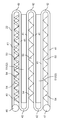
- FIG. 3 is a plan view showing the heat exchanger for refrigeration according to the first embodiment.
- FIG. 4 is a front view showing the heat exchanger for refrigeration according to the first embodiment.
- FIG. 5 is a cross-sectional view taken along the line VV of FIG.
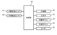
- FIG. 6 is a block diagram showing a control configuration of the first embodiment.
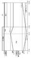
- FIG. 7 is a graph showing an operation corresponding to a demand response.
- FIG. 8 is a plan view showing a heat exchanger according to another embodiment of the present disclosure.
- FIG. 9 is a plan view showing a heat exchanger according to another embodiment of the present disclosure.
- FIG. 10 is a front view showing a heat exchanger according to another embodiment of the present disclosure.
- FIG. 11 is a front view showing a heat exchanger according to another embodiment of the present
- this conventional technology is applied to car air conditioners for vehicles, it is supplementarily cooled by a cold storage material while the engine is stopped, for example, during idling stop.
- a cold storage material due to the installation space, it is not possible to secure a large capacity of the cold storage material. Therefore, the inventors have discovered a problem that this conventional technique cannot be applied to a refrigerator as it is, and in order to solve the problem, they have constructed the subject matter of the present disclosure.
- the present disclosure provides a heat exchanger and a refrigerator that can efficiently cool the inside of the refrigerator and improve energy saving.
- FIG. 1 is a schematic cross-sectional configuration diagram showing an outline of the refrigerator according to the first embodiment of the present disclosure.
- the refrigerator 1 includes a box-shaped main body 10.
- a partition plate 11 for partitioning the internal space of the main body 10 is provided at a substantially central portion in the vertical direction of the main body 10.
- the upper side of the partition plate 11 is a refrigerating chamber 12, and the lower side of the partition plate 11 is a freezing chamber 13.
- a refrigerating room door 14 is provided openable and closable on the front surface of the refrigerating room 12, and a freezing room door 15 is provided openable and closable on the front surface of the freezing room 13.
- a refrigerating duct 20 extending in the vertical direction is provided at the rear of the refrigerating chamber 12.
- a freezing duct 21 extending in the vertical direction is provided at the rear of the freezing chamber 13.
- a refrigerating heat exchanger 22 as an example of the heat exchanger of the present disclosure is housed.
- a refrigerating fan 23 is arranged above the refrigerating heat exchanger 22.
- the refrigerator 1 sucks the internal air of the refrigerating chamber 12 from below the refrigerating duct 20, exchanges heat through the refrigerating heat exchanger 22, and then cools the refrigerating duct 20. It is configured to be blown into the inside of the refrigerating chamber 12 from above.
- a freezing heat exchanger 24 is housed inside the freezing duct 21.
- a freezing fan 25 is arranged above the refrigerating heat exchanger 24. By driving the freezing fan 25, the refrigerator 1 sucks the internal air of the freezing chamber 13 from below the freezing duct 21, exchanges heat through the freezing heat exchanger 24, and then the freezing duct 21. It is configured to be blown into the inside of the freezing chamber 13 from above.
- a heater 26 is arranged below the freezing duct 21.
- a compressor 30 is installed above the rear part of the main body 10.
- a condenser 31 is connected to the compressor 30 via a refrigerant pipe 32.
- a three-way valve 33 is connected to the condenser 31 via a refrigerant pipe 32, and a refrigerating heat exchanger 22 is connected to the three-way valve 33 via an expansion mechanism 34.
- a refrigerating heat exchanger 24 is connected to the three-way valve 33 via an expansion mechanism 35.
- a refrigerating refrigerant cycle is formed in which the refrigerant sequentially circulates through the compressor 30, the condenser 31, the three-way valve 33, the expansion mechanism 34, and the refrigerating heat exchanger 22. Further, a refrigerating refrigerant cycle is formed in which the refrigerant sequentially circulates through the compressor 30, the condenser 31, the three-way valve 33, the expansion mechanism 35, and the refrigerating heat exchanger 24.
- the refrigerating refrigerant cycle and the freezing refrigerant cycle can be switched by switching the three-way valve 33.
- FIG. 2 is a perspective view showing the refrigerating heat exchanger 22 of the first embodiment.
- FIG. 3 is a plan view showing the refrigerating heat exchanger 22 of the first embodiment.
- FIG. 4 is a front view showing the refrigerating heat exchanger 22 of the first embodiment.
- FIG. 5 is a cross-sectional view taken along the line VV of FIG.
- the refrigerating heat exchanger 22 includes a refrigerant conduction member 40 through which a refrigerant flows.
- the refrigerant conduction member 40 is composed of a perforated flat tube in which a plurality of substantially square passages are continuously arranged.
- the refrigerant conduction member 40 is formed in a meandering shape including a plurality of flat pipes 41 formed substantially parallel to each other at predetermined intervals and a plurality of curved portions 42 connecting the ends of the flat pipes 41. .. That is, the refrigerant conduction member 40 is configured so that the flow path through which the refrigerant flows meanders.
- the refrigerant conduction member 40 is configured by arranging six flat pipes 41 between headers, which will be described later.
- the number of flat tubes 41 is not limited to this, and can be set arbitrarily.
- each flat tube 41 and each curved portion 42 may be integrally configured, and one flat tube 41 may be meandered and arranged between the headers.
- the flat tube 41 and the curved portion 42 are vertically divided into three regions, that is, an upper region 43, a middle region 44, and a lower region 45.
- the region is divided into three regions in the vertical direction, but it may be divided into two regions or four or more regions in the vertical direction.
- an inlet side header 46 and an outlet side header 47 are provided at one end in the extending direction of the flat pipe 41, respectively.
- the inlet side header 46 and the exit side header 47 are provided so as to extend in the vertical direction.
- the inlet side header 46 and the outlet side header 47 are attached so as not to protrude from the end face of the refrigerant conduction member 40.
- the end faces of the inlet side header 46 and the outlet side header 47 are flush with the outer surface of the flat pipe 41 of the refrigerant conduction member 40.
- the thickness dimension of the refrigerant conducting member 40 (the dimension of the refrigerant conducting member 40 in the arrangement direction of the flat pipes 41) can be reduced. Therefore, when the refrigerant conduction member 40 is housed inside the refrigerating duct 20, the internal space of the refrigerating duct 20 can be reduced. As a result, the internal space of the refrigerator compartment 12 can be increased.
- the refrigerant is configured to flow in from the upper part of the inlet side header 46, and the refrigerant is configured to flow out from the lower part of the outlet side header 47.
- the inlet side header 46 and the outlet side header 47 are provided at different ends of the flat pipe 41 in the extending direction, and the inlet side header 46 and the outlet side header 47 are arranged on both sides of the refrigerant conduction member 40. You may do so.
- the refrigerant inlet of the inlet side header 46 may be provided below instead of above, and the refrigerant outlet of the outlet side header 47 may be provided above instead of below.
- a partition plate 48 is provided at a position corresponding to the boundary between the upper region 43 and the middle region 44 of the inlet side header 46.
- the portion corresponding to the middle region 44 of the entrance side header 46 and the portion corresponding to the lower region 45 communicate with each other.
- a partition plate 49 is provided at a position corresponding to the boundary between the middle region 44 and the lower region 45 of the exit side header 47.
- the portion corresponding to the upper region 43 of the exit side header 47 and the portion corresponding to the middle region 44 communicate with each other.
- the refrigerant flowing in from the upper part of the inlet side header 46 passes through the inside of the upper region 43 of the refrigerant conduction member 40 and flows to the outlet side header 47.
- the refrigerant flowing to the outlet side header 47 flows into the central region 44 of the refrigerant conduction member 40, flows to the inlet side header 46, flows through the lower region 45 via the inlet side header 46, and then flows to the lower part of the outlet side header 47. Leaked from.
- the refrigerant conducting member 40 is arranged so that its width direction (vertical direction in FIG. 4, that is, the flat direction of the flat tube 41) is directed to the air flow direction in the refrigerating duct 20, and the refrigerant conducting member 40 is arranged.
- the flowing refrigerant flows in a direction orthogonal to the air flow direction.
- the flat direction here means the longitudinal direction in the cross section (FIG. 5) of the flat tube 41.
- the air flow path 50 and the cold storage material container 52 in which the cold storage material 51 is enclosed are alternately arranged between the flat pipes 41 of the refrigerant conduction member 40.
- a holding member 53 for holding the cold storage material container 52 is provided on the lower surface of the flat pipe 41 of the refrigerant conduction member 40.
- the air flow path 50 is formed in the outermost part and the central part, and the cold storage material container 52 is arranged between the adjacent air flow paths 50.
- Fins 54 are arranged inside the air flow path 50.
- the fins 54 are continuously provided by being inclined at a predetermined angle with respect to the flat tube 41 and being bent in a zigzag shape. These fins 54 continuously form an air flow path 50 having a substantially triangular cross-sectional shape inside the air flow path 50.
- an air flow path having a rectangular cross-sectional shape may be continuously formed.
- the air flow path 50 is formed in the vertical direction (gravity direction) along the vertical direction of the refrigerating duct 20.
- the air inside the refrigerator flowing from the lower side to the upper side of the refrigerating duct 20 flows through the air flow path 50, and at this time, heat exchange with the refrigerant flowing inside the refrigerant conducting member 40. It is configured to be cooled to a predetermined temperature by doing so. Further, the refrigerating heat exchanger 22 is configured such that the cold storage material 51 is also cooled to a predetermined temperature by exchanging heat between the refrigerant flowing inside the refrigerant conduction member 40 and the cold storage material 51.
- the cold storage material 51 needs to cool the low temperature chamber (about -3 ° C) in the refrigerating chamber 12 which is cooled to about 3 ° C. Therefore, a cold storage material 51 having a melting point lower than ⁇ 3 ° C., for example, a cold storage material 51 having a melting point of ⁇ 5 ° C. to ⁇ 15 ° C. is used.
- the lower end of the fin 54 is located below the lower end of the refrigerant conducting member 40.
- the upper end of the fin 54 may be positioned above the upper end of the refrigerant conduction member 40. As a result, since the fins 54 are cooled by the refrigerant, the heat exchange efficiency of the air inside the refrigerator can be improved.
- FIG. 6 is a block diagram showing the control configuration of the first embodiment.
- the refrigerator 1 includes a control unit 60.
- the control unit 60 includes, for example, a processor that executes programs such as a CPU (Central Processing Unit) and an MPU (Micro-processing unit), and a memory such as a ROM (Read only memory) and a RAM (Random access memory). , Various processes are executed by the cooperation of hardware and software so as to read the control program stored in the memory and execute the processes.
- a processor Central Processing Unit
- MPU Micro-processing unit
- a memory such as a ROM (Read only memory) and a RAM (Random access memory).
- the control unit 60 controls the compressor 30, the refrigerating fan 23, the refrigerating fan 25, the three-way valve 33, and the heater 26 based on the detection temperatures of the refrigerating room temperature sensor 61 and the refrigerating room temperature sensor 62.
- the refrigerant sent to the refrigerating heat exchanger 22 flows in from the inlet side header 46 of the refrigerant conduction member 40 and flows inside the upper region 43.
- the refrigerant flowing to the outlet side header 47 flows through the central region 44 via the outlet side header 47, is sent to the inlet side header 46, and flows through the lower region 45 via the inlet side header 46.
- the refrigerant flowing through the lower region 45 flows out from the outlet side header 47 and is returned to the compressor 30.
- the air inside the refrigerator compartment 12 exchanges heat with the refrigerant flowing through the refrigerant conduction member 40 and is cooled.
- the cold storage material 51 is also cooled by the refrigerant flowing through the refrigerant conduction member 40.
- the refrigerant sent to the refrigerating heat exchanger 24 exchanges heat with the internal air flowing from below to above the refrigerating duct 21 by driving the refrigerating fan 25, and the refrigerant cooled by the refrigerant is refrigerated. Returned to room 13.
- DR Demand Response
- Demand response is the power consumption of the entire society by curbing the power consumption of factories and households in response to requests from electric power companies at the timing when the power consumption of the entire society reaches its peak (for example, around 14:00 in the summer). It is a mechanism to reduce the peak value of consumption.
- FIG. 7 is a graph showing the operation corresponding to the demand response.
- the control of the present embodiment is a control of stopping the compressor 30 in a time zone of 1 hour before and after 14:00, which is the peak of power consumption.
- the refrigerator 1 receives a demand response signal requesting reduction of power consumption from an external server such as an electric power company at 11 o'clock.
- an external server such as an electric power company at 11 o'clock.
- the device that has received the demand response signal needs to be switched to the operation of suppressing the power consumption after 2 hours.
- the refrigerator 1 When the refrigerator 1 receives the demand response signal, the refrigerator 1 starts the demand response control. Specifically, the control unit 60 switches the three-way valve 33 at 11 o'clock to control the flow of the refrigerant to the refrigerating heat exchanger 24.
- the refrigerant discharged from the compressor 30 is sent to the refrigerating heat exchanger 24 through the condenser 31 and the expansion mechanism 35.
- the refrigerant sent to the refrigerating heat exchanger 24 exchanges heat with the internal air in the refrigerating heat exchanger 24 to cool the inside of the freezing chamber 13 to a predetermined temperature.
- the predetermined temperature in this case is usually set lower than the set internal temperature.
- the cooling is controlled to, for example, from about -19 ° C to about -24 ° C.
- control unit 60 switches the three-way valve 33 to control the flow of the refrigerant to the refrigerating heat exchanger 22.
- the refrigerant discharged from the compressor 30 is sent to the refrigerating heat exchanger 22 through the condenser 31 and the expansion mechanism 34.
- the refrigerant sent to the refrigerating heat exchanger 22 exchanges heat with the internal air in the refrigerating heat exchanger 22 to cool the inside of the refrigerating chamber 12 to a predetermined temperature.
- the cold storage material 51 is cooled by the refrigerant flowing through the refrigerating heat exchanger 22, and the cold storage material 51 is stored cold.
- the control unit 60 stops the compressor 30. By stopping the compressor 30, the refrigerator 1 executes an operation of suppressing power consumption.
- the temperature of the refrigerating chamber 12 can be maintained at a substantially constant temperature due to the cooling capacity of the cold storage material 51. Although the temperature of the freezing chamber 13 gradually rises, it can be maintained at an appropriate temperature even at 15:00 when the demand response control ends.
- the heat exchanger of the present embodiment is arranged between the refrigerant conducting member 40 made of the flat tubes 41 formed at intervals from each other and the adjacent flat tubes 41 of the refrigerant conducting members 40. It includes a cold storage material 51 container in which a cold storage material 51 is sealed, an air flow path 50 formed between other flat pipes 41 and through which air flows, and fins 54 provided in the air flow path 50.
- the width direction of the refrigerant conduction member 40 is directed to the ventilation direction, and the ventilation direction of the air flow path 50 is the gravity direction.
- the width direction of the refrigerant conduction member 40 is directed to the ventilation direction, and the ventilation direction of the air flow path 50 is the gravity direction. Therefore, when frost or dew condensation adheres to the fin 54, dew condensation water is formed. It can be drained by its own weight. Therefore, the amount of dew condensation water remaining on the fins 54 can be reduced. Therefore, it is possible to suppress an increase in ventilation resistance due to dew condensation water and a reduction in the heat exchange area between the fin 54 and the air inside the refrigerator, and it is possible to efficiently cool the inside of the refrigerator chamber 12. Further, the cold storage material 51 can be cooled by the heat exchanger, and the internal air can be cooled by the cold storage material 51, so that the energy saving performance can be improved.
- the lower end of the fin 54 is located below the lower end of the refrigerant conducting member 40.
- the refrigerant conduction member 40 includes a holding member 53 that holds the cold storage material container 52.
- the refrigerating heat exchanger 22 is arranged so that the cold storage material container 52 of the refrigerant conduction member 40 is located in the vertical direction (gravity direction), the cold storage material container 52 can be supported. Therefore, it is possible to prevent the cold storage material container 52 from falling.
- the refrigerant conduction member 40 includes an inlet side header 46 and an outlet side header 47 of the refrigerant, and the inlet side header 46 and the outlet side header 47 do not protrude from the end face of the refrigerant conduction member 40. It is attached to.
- the thickness dimension of the refrigerant conduction member 40 can be reduced. Therefore, when the refrigerant conduction member 40 is housed inside the refrigerating duct 20, the internal space of the refrigerating duct 20 can be reduced. Therefore, the internal space of the refrigerator compartment 12 can be increased.
- the first embodiment has been described as an example of the technique disclosed in the present application.
- the technique in the present disclosure is not limited to this, and can be applied to embodiments in which changes, replacements, additions, omissions, etc. have been made. It is also possible to combine the components described in the first embodiment to form a new embodiment.
- FIG. 8 is a plan view showing a heat exchanger according to another embodiment of the present disclosure.
- the fins 54 in the lower region 45 and the fins 54 in the upper region 43 are arranged so as to be offset from each other. More specifically, the fins 54 in the lower region 45 and the fins 54 in the upper region 43 are arranged so that the repeating phases of the zigzag shape are shifted by 1/2.
- the triangular air flow path 50 in the upper region 43 and the triangular air flow path 50 in the lower region 45 are formed so as to overlap each other in a plan view.
- the phase here means a repeating phase in which the triangular shape of the fins 54 forming the air flow path 50 is one unit (one cycle).
- the phase of the fins 54 of the middle region 44 may be shifted from the fins 54 of the upper region 43.
- FIG. 9 is a plan view showing a heat exchanger according to another embodiment of the present disclosure.
- the fins 54 in the lower region 45 and the fins 54 in the upper region 43 are arranged so as to be offset from each other. More specifically, the inclination angle of the fin 54 of the lower region 45 on the upstream side of the air flow path is formed to be larger than the inclination angle of the fin 54 of the upper region 43 on the downstream side of the air flow path. be.
- FIG. 9 shows a partial combination of a view of the fin 54 viewed from the upper region 43 and a view of the fin 54 viewed only from the lower region 45 in a plan view.
- the fin 54 of the lower region 45 is formed at a large angle corresponding to the apex of the triangular air flow path 50.
- the refrigerating fan 23 is rotated in the reverse direction to make the upper region 43 the upstream side of the air flow path 50.
- the lower region 45 may be the downstream side of the air flow path 50.
- FIG. 10 is a front view showing a heat exchanger according to another embodiment of the present disclosure.
- the refrigerating heat exchanger 22 is provided with a liquid refrigerant reservoir 55.
- a refrigerant outlet 47a is provided above the outlet side header 47, and a refrigerant pipe 32 through which the refrigerant flows is connected to the refrigerant outlet 47a.
- the refrigerant outlet 47a of the outlet side header 47 is arranged above the upper end of the flat pipe 41 constituting the refrigerant conduction member 40.
- a refrigerant inlet 46a is provided below the inlet side header 46, and a refrigerant pipe 32 is connected to the refrigerant inlet 46a.
- the refrigerant flowing in from the refrigerant inlet 46a of the inlet side header 46 is sent from the lower region 45 to the upper region 43 via the middle region 44, and flows out from the refrigerant outlet 47a of the outlet side header 47. Will be done.
- FIG. 11 is a front view showing a heat exchanger according to another embodiment of the present disclosure.
- the refrigerating heat exchanger 22 is provided with the liquid refrigerant reservoir 55.
- a refrigerant outlet 47a is provided below the outlet side header 47, and a refrigerant pipe 32 through which the refrigerant flows is connected to the refrigerant outlet 47a.
- the refrigerant outlet 47a of the outlet side header 47 is arranged above the upper end of the flat pipe 41 in the lower region 45.
- the refrigerant inlet 46a of the inlet side header 46 is provided at the upper end portion of the inlet side header 46.
- the refrigerant flowing in from the refrigerant inlet 46a of the inlet side header 46 is sent from the upper region 43 to the lower region 45 via the middle region 44, and flows out from the refrigerant outlet 47a of the outlet side header 47. NS.
- a cold storage material 51 may be provided in the refrigerating heat exchanger 24 as in the refrigerating heat exchanger 22.
- the melting point of the cold storage material 51 is preferably ⁇ 20 ° C. to ⁇ 30 ° C.
- the width direction of the refrigerant conduction member is directed to the ventilation direction, and the ventilation direction of the air flow path is the gravity direction, so that the air inside the refrigerator compartment flows in the gravity direction.
- Refrigerant 10 Main body 11 Partition plate 12 Refrigerator room 13 Refrigerator room 14 Refrigerator room door 15 Refrigerator room door 20 Refrigerant duct 21 Refrigerant duct 22 Refrigerant heat exchanger 23 Refrigerator fan 24 Refrigerator heat exchanger 25 Refrigerator fan 26 Heater 30 Compressor 31 Condenser 32 Refrigerant piping 33 Three-way valve 34 Expansion mechanism 35 Expansion mechanism 40 Refrigerant conduction member 41 Flat tube 42 Curved part 43 Upper area 44 Middle area 45 Lower area 46 Inlet side header 46a Refrigerant inlet 47 Exit side header 47a Refrigerant outlet 48 Partition plate 49 Partition plate 50 Air flow path 51 Cold storage material 52 Cold storage material container 53 Holding member 54 Fin 55 Refrigerant pool 60 Control unit 61 Refrigerating room temperature sensor 62 Refrigerating room temperature sensor
Landscapes
- Engineering & Computer Science (AREA)
- Physics & Mathematics (AREA)
- Mechanical Engineering (AREA)
- Thermal Sciences (AREA)
- General Engineering & Computer Science (AREA)
- Chemical & Material Sciences (AREA)
- Combustion & Propulsion (AREA)
- Devices That Are Associated With Refrigeration Equipment (AREA)
- Heat-Exchange Devices With Radiators And Conduit Assemblies (AREA)
- Removal Of Water From Condensation And Defrosting (AREA)
Priority Applications (1)
| Application Number | Priority Date | Filing Date | Title |
|---|---|---|---|
| CN202180023329.8A CN115315602A (zh) | 2020-05-29 | 2021-05-26 | 热交换器和冷藏库 |
Applications Claiming Priority (2)
| Application Number | Priority Date | Filing Date | Title |
|---|---|---|---|
| JP2020094749A JP2021188836A (ja) | 2020-05-29 | 2020-05-29 | 熱交換器および冷蔵庫 |
| JP2020-094749 | 2020-05-29 |
Publications (1)
| Publication Number | Publication Date |
|---|---|
| WO2021241619A1 true WO2021241619A1 (ja) | 2021-12-02 |
Family
ID=78744572
Family Applications (1)
| Application Number | Title | Priority Date | Filing Date |
|---|---|---|---|
| PCT/JP2021/019932 Ceased WO2021241619A1 (ja) | 2020-05-29 | 2021-05-26 | 熱交換器および冷蔵庫 |
Country Status (3)
| Country | Link |
|---|---|
| JP (3) | JP2021188836A (https=) |
| CN (1) | CN115315602A (https=) |
| WO (1) | WO2021241619A1 (https=) |
Families Citing this family (4)
| Publication number | Priority date | Publication date | Assignee | Title |
|---|---|---|---|---|
| JP7788614B2 (ja) * | 2021-10-13 | 2025-12-19 | パナソニックIpマネジメント株式会社 | 冷蔵庫 |
| JP2023161995A (ja) * | 2022-04-26 | 2023-11-08 | パナソニックIpマネジメント株式会社 | 冷却器 |
| JP7660304B2 (ja) * | 2022-09-30 | 2025-04-11 | パナソニックIpマネジメント株式会社 | 冷却装置、冷却装置の運転方法および冷却装置の制御システム |
| CN116558171A (zh) * | 2023-05-25 | 2023-08-08 | 安徽艾其味食品有限公司 | 基于冷藏库的换气装置 |
Citations (6)
| Publication number | Priority date | Publication date | Assignee | Title |
|---|---|---|---|---|
| JPH11264675A (ja) * | 1998-03-19 | 1999-09-28 | Zexel:Kk | 並設一体型熱交換器 |
| JP2010149814A (ja) * | 2008-12-26 | 2010-07-08 | Showa Denko Kk | 蓄冷機能付きエバポレータ |
| WO2013011945A1 (ja) * | 2011-07-20 | 2013-01-24 | ダイキン工業株式会社 | 熱交換器用扁平管 |
| JP2014044002A (ja) * | 2012-08-27 | 2014-03-13 | Sumitomo Precision Prod Co Ltd | 熱交換ユニット |
| JP2014159891A (ja) * | 2013-02-19 | 2014-09-04 | Sharp Corp | 蒸発器及びそれを用いた冷蔵庫 |
| WO2019207799A1 (ja) * | 2018-04-27 | 2019-10-31 | 日立ジョンソンコントロールズ空調株式会社 | 空気調和機および熱交換器 |
Family Cites Families (20)
| Publication number | Priority date | Publication date | Assignee | Title |
|---|---|---|---|---|
| JPH01129587U (https=) * | 1988-02-23 | 1989-09-04 | ||
| JP2000161647A (ja) * | 1998-12-01 | 2000-06-16 | Babcock Hitachi Kk | 排ガス処理装置とガス再加熱器 |
| JP2001255093A (ja) * | 2000-03-09 | 2001-09-21 | Zexel Valeo Climate Control Corp | 蒸発器 |
| JP2003139456A (ja) * | 2001-11-05 | 2003-05-14 | Nippon Kentetsu Co Ltd | 冷凍冷蔵ショーケースの庫内温度制御方法 |
| US20080184732A1 (en) * | 2005-01-14 | 2008-08-07 | Jens Hadler | Evaporator, in Particular for an Air-Conditioning System of a Motor Vehicle |
| JP5010324B2 (ja) * | 2007-03-29 | 2012-08-29 | 三菱重工業株式会社 | 多湿気体の冷却方法及び装置 |
| JP5764335B2 (ja) * | 2011-01-28 | 2015-08-19 | 株式会社ケーヒン・サーマル・テクノロジー | 蓄冷機能付きエバポレータ |
| JP5409704B2 (ja) * | 2011-05-24 | 2014-02-05 | 三菱電機株式会社 | 冷蔵庫 |
| JP2013119959A (ja) * | 2011-12-06 | 2013-06-17 | Showa Denko Kk | オフセットフィンおよびその製造方法 |
| JP2013185721A (ja) * | 2012-03-06 | 2013-09-19 | Daikin Industries Ltd | 熱交換用扁平管及び熱交換器 |
| WO2015025365A1 (ja) * | 2013-08-20 | 2015-02-26 | 三菱電機株式会社 | 熱交換器、空調機及び冷凍サイクル装置 |
| JP2015055410A (ja) * | 2013-09-11 | 2015-03-23 | ダイキン工業株式会社 | 熱交換器の製造方法、熱交換器及び空気調和機 |
| JP2016003831A (ja) * | 2014-06-18 | 2016-01-12 | シャープ株式会社 | 冷蔵庫 |
| CN104154682B (zh) * | 2014-08-20 | 2016-05-25 | 上海加冷松芝汽车空调股份有限公司 | 一种蓄冷式蒸发器 |
| JP6511974B2 (ja) * | 2015-06-09 | 2019-05-15 | 株式会社豊田中央研究所 | 化学蓄熱反応器、化学蓄熱システム |
| JP6593153B2 (ja) * | 2015-12-21 | 2019-10-23 | 株式会社豊田中央研究所 | 化学蓄熱反応器、及び化学蓄熱システム |
| JP2017146023A (ja) * | 2016-02-17 | 2017-08-24 | 東芝ライフスタイル株式会社 | 冷蔵庫 |
| JP7164286B2 (ja) * | 2016-04-27 | 2022-11-01 | 東芝ライフスタイル株式会社 | 冷蔵庫 |
| JP2018048769A (ja) * | 2016-09-21 | 2018-03-29 | 豊田通商株式会社 | 熱交換器 |
| JP6732647B2 (ja) * | 2016-12-08 | 2020-07-29 | 三菱重工業株式会社 | 熱交換器 |
-
2020
- 2020-05-29 JP JP2020094749A patent/JP2021188836A/ja active Pending
-
2021
- 2021-05-26 WO PCT/JP2021/019932 patent/WO2021241619A1/ja not_active Ceased
- 2021-05-26 CN CN202180023329.8A patent/CN115315602A/zh active Pending
-
2023
- 2023-07-07 JP JP2023112392A patent/JP7627858B2/ja active Active
-
2024
- 2024-11-06 JP JP2024194295A patent/JP2025014066A/ja active Pending
Patent Citations (6)
| Publication number | Priority date | Publication date | Assignee | Title |
|---|---|---|---|---|
| JPH11264675A (ja) * | 1998-03-19 | 1999-09-28 | Zexel:Kk | 並設一体型熱交換器 |
| JP2010149814A (ja) * | 2008-12-26 | 2010-07-08 | Showa Denko Kk | 蓄冷機能付きエバポレータ |
| WO2013011945A1 (ja) * | 2011-07-20 | 2013-01-24 | ダイキン工業株式会社 | 熱交換器用扁平管 |
| JP2014044002A (ja) * | 2012-08-27 | 2014-03-13 | Sumitomo Precision Prod Co Ltd | 熱交換ユニット |
| JP2014159891A (ja) * | 2013-02-19 | 2014-09-04 | Sharp Corp | 蒸発器及びそれを用いた冷蔵庫 |
| WO2019207799A1 (ja) * | 2018-04-27 | 2019-10-31 | 日立ジョンソンコントロールズ空調株式会社 | 空気調和機および熱交換器 |
Also Published As
| Publication number | Publication date |
|---|---|
| JP2023118975A (ja) | 2023-08-25 |
| JP2021188836A (ja) | 2021-12-13 |
| JP7627858B2 (ja) | 2025-02-07 |
| CN115315602A (zh) | 2022-11-08 |
| JP2025014066A (ja) | 2025-01-28 |
Similar Documents
| Publication | Publication Date | Title |
|---|---|---|
| JP7627858B2 (ja) | 冷蔵庫 | |
| JP5772748B2 (ja) | 蒸発器 | |
| JP5868088B2 (ja) | 車両用空調装置のクーリングユニット | |
| JP5764335B2 (ja) | 蓄冷機能付きエバポレータ | |
| JP2013061136A5 (https=) | ||
| KR101611694B1 (ko) | 관-핀 축열 증발기 | |
| JP2025142350A (ja) | 熱交換器および冷蔵庫 | |
| JP4618529B2 (ja) | 氷蓄熱式空気調和装置 | |
| JP2006284133A (ja) | 熱交換器 | |
| WO2014129621A1 (ja) | 熱交換器及び車両用空調装置 | |
| JP4633967B2 (ja) | 氷蓄熱式空気調和装置 | |
| JPH07167548A (ja) | 冷凍冷蔵庫 | |
| JP6511710B2 (ja) | 冷凍装置 | |
| JP2003314947A (ja) | 熱交換器ユニットおよび冷蔵庫 | |
| JP7759536B2 (ja) | 冷蔵庫 | |
| KR100485140B1 (ko) | 핀튜브를 이용한 빙축기 및 이를 이용한 냉방시스템 | |
| JP3886244B2 (ja) | 熱交換器 | |
| JP2017030391A (ja) | 車両用空調装置 | |
| JP2024089045A (ja) | 冷凍装置および負荷冷却器のデフロスト方法 | |
| JP2726941B2 (ja) | 換気用熱交換器 | |
| JPH0233028Y2 (https=) | ||
| KR100547668B1 (ko) | 자동차 열교환기용 헤더탱크 | |
| JP3072209B2 (ja) | 蓄熱装置 | |
| JP3152175B2 (ja) | 冷凍コンテナ | |
| JP3788391B2 (ja) | 氷蓄熱装置 |
Legal Events
| Date | Code | Title | Description |
|---|---|---|---|
| 121 | Ep: the epo has been informed by wipo that ep was designated in this application |
Ref document number: 21812740 Country of ref document: EP Kind code of ref document: A1 |
|
| NENP | Non-entry into the national phase |
Ref country code: DE |
|
| 122 | Ep: pct application non-entry in european phase |
Ref document number: 21812740 Country of ref document: EP Kind code of ref document: A1 |