WO2021229765A1 - 刃物 - Google Patents
刃物 Download PDFInfo
- Publication number
- WO2021229765A1 WO2021229765A1 PCT/JP2020/019330 JP2020019330W WO2021229765A1 WO 2021229765 A1 WO2021229765 A1 WO 2021229765A1 JP 2020019330 W JP2020019330 W JP 2020019330W WO 2021229765 A1 WO2021229765 A1 WO 2021229765A1
- Authority
- WO
- WIPO (PCT)
- Prior art keywords
- blade
- concave
- cutting edge
- kitchen knife
- blades
- Prior art date
Links
Images


Classifications
-
- B—PERFORMING OPERATIONS; TRANSPORTING
- B26—HAND CUTTING TOOLS; CUTTING; SEVERING
- B26B—HAND-HELD CUTTING TOOLS NOT OTHERWISE PROVIDED FOR
- B26B9/00—Blades for hand knives
- B26B9/02—Blades for hand knives characterised by the shape of the cutting edge, e.g. wavy
Definitions
- the present invention relates to a blade having a blade having a corrugated cutting edge.
- a blade of this type for example, a kitchen knife for cutting bread and a rotary mechanical blade (see, for example, Patent Document 1).
- the cutting edge portion of the kitchen knife described in Patent Document 1 is formed with a continuous corrugated cutting edge, a so-called wave blade.
- This waveform is composed of a plurality of continuous arcuate recesses.
- the angle of the blade is relatively large so that the cutting edge is not chipped when forming a plurality of concave blades constituting the wave blade. Further, as the angle of the blade is increased, the unevenness of each concave blade in the thickness direction of the kitchen knife becomes larger. Therefore, when cutting the object, that is, when moving the cutting edge, there is a problem that the contact area with the object becomes large and the frictional resistance tends to increase.
- An object of the present invention is to provide a cutting tool having a corrugated cutting edge and capable of reducing frictional resistance when cutting an object.
- the blade for achieving the above object has two surfaces located on opposite sides of each other, and also includes a blade having a corrugated cutting edge. At least one surface of the blade body has a flat portion and an inclined portion that is inclined with respect to the flat portion and forms a part of the cutting edge, and the inclined portion includes the inclined portion of the cutting edge.
- a plurality of concave blades constituting a part are provided side by side.
- the angle of the blade in the portion between the concave blades adjacent to each other is smaller than the conventional configuration in which the flat portion itself is provided with a plurality of concave blades without having the inclined portion. Become.
- the unevenness of each concave blade in the thickness direction of the blade is reduced. Therefore, when cutting the object, that is, when moving the cutting edge, the contact area with the object becomes small and the frictional resistance becomes small. Therefore, it is possible to reduce the frictional resistance when cutting an object while having a corrugated cutting edge.
- the plurality of concave blades include a plurality of types of concave blades having different shapes or sizes.
- the frictional resistance when cutting an object can be freely set by appropriately setting the arrangement pattern of a plurality of types of concave blades.
- the blade constitutes a kitchen knife.
- FIG. 2 is a cross-sectional view taken along the line 3-3 of FIG. It is a figure corresponding to FIG. 1, and is the plan view which shows the state just before forming the inclined part.
- (a) is a plan view
- (b) is a plan view showing a state immediately before forming an inclined portion.
- the plan view of the rotary blade for a food processor which concerns on a modification.
- the kitchen knife 10 includes a long plate-shaped blade body 11 and a handle 18 provided at a base end portion of the blade body 11.
- the blade body 11 has a tapered shape whose width is smaller toward the tip side.
- the blade body 11 is made of a steel plate such as a stainless steel plate.
- the blade body 11 has a first surface 13 and a second surface (not shown) located on opposite sides of each other.
- the longitudinal direction of the kitchen knife 10, the width direction of the kitchen knife 10, and the thickness direction of the kitchen knife 10 will be described simply as the longitudinal direction, the width direction, and the thickness direction.
- a corrugated cutting edge 12 is provided on one edge of the blade 11 in the width direction.
- the first surface 13 of the blade body 11 has a flat portion 14 and an inclined portion 15 that is inclined with respect to the flat portion 14 and forms a part of the blade edge 12.
- the flat portion 14 extends substantially over the longitudinal direction of the blade 11. Further, the flat portion 14 extends from the base end of the cutting edge 12 to the edge of the blade body 11 opposite to the one side in the width direction.
- the inclined portion 15 is provided with a plurality of concave blades 16 constituting a part of the cutting edge 12 side by side in the longitudinal direction.
- the plurality of concave blades 16 include a plurality of types of concave blades 16A and 16B having different shapes and sizes.
- the plurality of concave blades 16 include a first concave blade 16A and a second concave blade 16B whose size in the width direction and the size in the longitudinal direction are both smaller than those of the first concave blade 16A.
- the first concave blade 16A and the second concave blade 16B are provided alternately in the longitudinal direction.
- the manufacturing method first includes a step of forming a corrugated cutting edge 22 with respect to the first surface 13 of the blade 11 on which the inclined portion 15 is not formed.
- the cutting edge 22 includes a first concave blade 26A, a first concave blade 26A, and a second concave blade 26B having a smaller width direction size and a longitudinal size than the first concave blade 26A.
- the first concave blade 26A and the second concave blade 26B are provided alternately.
- each valley portion P1 adjacent to the flat portion 14 in the first concave blade 26A and each mountain forming the cutting edge 22 in the portion 27 between the first concave blade 26A and the second concave blade 26B is included.
- the inclined portion 15 is formed.
- the kitchen knife 10 of this embodiment Compare the kitchen knife 10 of this embodiment with a conventional kitchen knife. Since the kitchen knife shown in FIG. 4 does not have the inclined portion 15 and has a configuration in which a plurality of concave blades 26A and 26B are provided on the flat portion 14 itself, it is considered to have the same configuration as a conventional kitchen knife. Can be done. As shown in FIG. 3, in the kitchen knife 10 of the present embodiment, the angle ⁇ of the blade in the portion 17 between the concave blades 16 adjacent to each other is smaller than that of the conventional kitchen knife indicated by the alternate long and short dash line. As a result, the unevenness of each concave blade 16 in the thickness direction of the blade 11 is reduced. Therefore, when cutting the object, that is, when moving the cutting edge 12, the contact area with the object becomes small and the frictional resistance becomes small.
- the first surface 13 of the blade body 11 has a flat portion 14 and an inclined portion 15 that is inclined with respect to the flat portion 14 and forms a part of the cutting edge 12.
- a plurality of concave blades 16 constituting a part of the cutting edge 12 are provided side by side on the inclined portion 15.
- the plurality of concave blades 16 include a plurality of types of concave blades 16A and 16B having different shapes and sizes.
- the frictional resistance when cutting an object can be freely set by appropriately setting the arrangement pattern of a plurality of types of concave blades 16A and 16B.
- the arrangement pattern of the first concave blade 16A and the second concave blade 16B can be changed as appropriate.
- two second concave blades 16B may be arranged between the first concave blades 16A.
- a plurality of concave blades 16 include two types of concave blades 16A and 16B having different shapes and sizes, but the plurality of concave blades have three or more types. It may include a concave blade.
- the shape of the plurality of concave blades 16 may include only one type of concave blade.
- the concave blade 16 as shown in FIG. 6A may be used.
- the corrugated cutting edge 22 is formed with respect to the first surface 13 of the blade 11.
- the cutting edge 22 is composed of a plurality of concave blades 26 having the same shape and size.
- the flat portion 14 and A part of the concave blade 26 is removed by polishing. As a result, the inclined portion 15 is formed.
- the inclined portion 15 constituting the cutting edge 12 is provided on the first surface 13 of the blade body 11, but the inclined portion 15 is also provided on the second surface opposite to the first surface 13. May be good. Further, a plurality of concave blades constituting a part of the cutting edge may be provided on the inclined portion 15 provided on the second surface.
- the knife according to the present invention is not limited to kitchen knives.
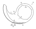
- the present invention can be applied to a rotary blade of a food processor.
- the rotary blade 30 has an annular mounting portion 38 having an insertion hole 38a into which the rotating body is inserted, and a blade body 31 extending from the mounting portion 38.
- the blade body 31 has a corrugated cutting edge 32.
- the first surface 33 of the blade body 31 has a flat portion 34 and an inclined portion 35 that is inclined with respect to the flat portion 34 and forms a part of the cutting edge 32.
- a plurality of concave blades 36 forming a part of the cutting edge 32 are provided side by side on the inclined portion 35.
- the plurality of concave blades 36 include a first concave blade 36A and a second concave blade 36B having different shapes and sizes from each other.
Landscapes
- Life Sciences & Earth Sciences (AREA)
- Forests & Forestry (AREA)
- Engineering & Computer Science (AREA)
- Mechanical Engineering (AREA)
- Knives (AREA)
Abstract
包丁は、互いに反対側に位置する2つの面を有するとともに、波形の刃先を有する刃体を備える。刃体の第1面は、平部と、平部に対して傾斜するとともに刃先の一部を構成する傾斜部とを有している。傾斜部には、刃先の一部を構成する複数の凹刃が並んで設けられている。
Description
本発明は、波形の刃先を有する刃体を備える刃物に関する。
従来、この種の刃物としては、例えばパン切り用の包丁や回転式機械刃がある(例えば特許文献1参照)。
特許文献1に記載の包丁の切刃部分には、連続する波形の刃先、所謂波刃が形成されている。この波形は、連続する複数の弧状凹部により構成されている。
ところで、こうした波刃を有する刃物においては、波刃を構成する複数の凹刃を形成する際に刃先が欠けないように刃の角度が比較的大きくされている。また、刃の角度が大きくされることに伴って包丁の厚さ方向における各凹刃の凹凸が大きくなる。そのため、対象物を切る際、すなわち刃先を移動させる際に、対象物との接触面積が大きくなり、摩擦抵抗が大きくなりやすいという問題がある。
本発明の目的は、波形の刃先を有しつつ、対象物を切る際の摩擦抵抗を小さくすることのできる刃物を提供することにある。
上記目的を達成するための刃物は、互いに反対側に位置する2つの面を有するとともに、波形の刃先を有する刃体を備える。前記刃体の少なくとも一方の面は、平部と、前記平部に対して傾斜するとともに前記刃先の一部を構成する傾斜部と、を有しており、前記傾斜部には、前記刃先の一部を構成する複数の凹刃が並んで設けられている。
同構成によれば、上記傾斜部を有しておらず、複数の凹刃が平部自体に設けられる従来の構成に比べて、互いに隣り合う凹刃同士の間の部分における刃の角度が小さくなる。これにより、刃体の厚さ方向における各凹刃の凹凸が小さくなる。そのため、対象物を切る際、すなわち刃先を移動させる際に、対象物との接触面積が小さくなり、摩擦抵抗が小さくなる。したがって、波形の刃先を有しつつ、対象物を切る際の摩擦抵抗を小さくすることができる。
上記刃物において、複数の前記凹刃は、形状または大きさの互いに異なる複数種類の凹刃を含んでいることが好ましい。
同構成によれば、複数種類の凹刃の配置パターンを適宜設定することによって、対象物を切る際の摩擦抵抗を自在に設定することができる。
上記刃物において、前記刃体は、包丁を構成するものであることが好ましい。
同構成によれば、包丁において、波形の刃先を有しつつ、対象物を切る際の摩擦抵抗を小さくすることができる。
本発明によれば、波形の刃先を有しつつ、対象物を切る際の摩擦抵抗を小さくすることができる。
以下、図1~図4を参照して、本発明に係る刃物を調理用の包丁として具体化した一実施形態について説明する。
図1に示すように、包丁10は、長尺板状の刃体11と、刃体11の基端部に設けられる柄18とを備えている。刃体11は、先端側ほど幅が小さい先細形状である。刃体11は、ステンレス鋼板などの鋼板製である。刃体11は、互いに反対側に位置する第1の面13及び第2の面(図示しない)を有する。
なお、以降において、包丁10の長手方向、包丁10の幅方向、及び包丁10の厚さ方向を、単に長手方向、幅方向、及び厚さ方向として説明する。
図1及び図2に示すように、刃体11における幅方向の一側の縁には、波形の刃先12が設けられている。
図2に示すように、刃体11の第1面13は、平部14と、平部14に対して傾斜するとともに刃先12の一部を構成する傾斜部15とを有している。平部14は、刃体11における長手方向の略全体にわたって延びている。また、平部14は、刃先12の基端から刃体11における幅方向の上記一側とは反対側の縁まで延びている。
傾斜部15には、刃先12の一部を構成する複数の凹刃16が長手方向において並んで設けられている。
複数の凹刃16は、形状及び大きさの互いに異なる複数種類の凹刃16A,16Bを含んでいる。複数の凹刃16は、第1凹刃16Aと、第1凹刃16Aよりも幅方向の大きさ及び長手方向の大きさが共に小さい第2凹刃16Bとを含んでいる。本実施形態では、第1凹刃16Aと第2凹刃16Bとが長手方向において交互に設けられている。
次に、包丁10の製造方法について説明する。
製造方法は、図4に示すように、まず、傾斜部15が形成されていない刃体11の第1面13に対して波形の刃先22を形成する工程を含む。
刃先22は、第1凹刃26Aと、第1凹刃26Aと、第1凹刃26Aよりも幅方向の大きさ及び長手方向の大きさが共に小さい第2凹刃26Bとを含んでいる。本実施形態では、第1凹刃26Aと第2凹刃26Bとが交互に設けられている。
製造方法は、次に、第1凹刃26Aにおいて平部14と隣接する各谷部P1と、第1凹刃26Aと第2凹刃26Bとの間の部分27において刃先22を構成する各山部P2とを含む仮想平面Vに沿って、平部14、第1凹刃26A及び第2凹刃26Bの一部を研磨により除去する工程を含む。これにより、傾斜部15が形成される。
次に、本実施形態の作用について説明する。
本実施形態の包丁10と従来の包丁を比較する。図4に示す包丁は、上記傾斜部15を有しておらず、複数の凹刃26A,26Bが平部14自体に設けられる構成を有するため、従来の包丁と同様の構成を有するとみなすことができる。図3に示すように、本実施形態の包丁10では、二点鎖線で示される従来の包丁に比べて、互いに隣り合う凹刃16同士の間の部分17における刃の角度αが小さい。これにより、刃体11の厚さ方向における各凹刃16の凹凸が小さくなる。そのため、対象物を切る際、すなわち刃先12を移動させる際に、対象物との接触面積が小さくなり、摩擦抵抗が小さくなる。
次に、本実施形態の作用及び効果について説明する。
(1)刃体11の第1面13は、平部14と、平部14に対して傾斜するとともに刃先12の一部を構成する傾斜部15とを有している。傾斜部15には、刃先12の一部を構成する複数の凹刃16が並んで設けられている。
こうした構成によれば、上記作用を奏することから、波形の刃先12を有しつつ、対象物を切る際の摩擦抵抗を小さくすることができる。
(2)複数の凹刃16は、形状及び大きさの互いに異なる複数種類の凹刃16A,16Bを含んでいる。
こうした構成によれば、複数種類の凹刃16A,16Bの配置パターンを適宜設定することによって、対象物を切る際の摩擦抵抗を自在に設定することができる。
<変更例>
上記実施形態は、例えば以下のように変更して実施することもできる。本実施形態及び以下の変更例は、技術的に矛盾しない範囲で互いに組み合わせて実施することができる。
上記実施形態は、例えば以下のように変更して実施することもできる。本実施形態及び以下の変更例は、技術的に矛盾しない範囲で互いに組み合わせて実施することができる。
・第1凹刃16A及び第2凹刃16Bの配置パターンは適宜変更できる。例えば、図5に示すように、第1凹刃16A同士の間に2つの第2凹刃16Bを配置するようにしてもよい。
・上記実施形態及びその変形例では、複数の凹刃16が、形状及び大きさの互いに異なる2種類の凹刃16A,16Bを含むものについて例示したが、複数の凹刃は、3種類以上の凹刃を含むものであってもよい。
・複数の凹刃16の形状は、1種類の凹刃のみを含むものであってもよい。この場合、例えば、図6(a)に示すような凹刃16であってもよい。この場合であっても、上記実施形態と同様に、まず、図6(b)に示すように、刃体11の第1面13に対して波形の刃先22を形成する。刃先22は、同一の形状及び大きさの複数の凹刃26により構成されている。次に、凹刃26において平部14と隣接する各谷部P1と、凹刃26同士の間の部分において刃先22となる各山部P2とを含む仮想平面Vに沿って、平部14及び凹刃26の一部を研磨により除去する。これにより、傾斜部15が形成される。
・上記実施形態では、刃体11の第1面13に刃先12を構成する傾斜部15を設けたが、第1面13とは反対側の第2面にも傾斜部15を設けるようにしてもよい。また、第2面に設けられた傾斜部15に刃先の一部を構成する複数の凹刃を設けるようにしてもよい。
・本発明に係る刃物は、包丁に限定されない。例えばフードプロセッサの回転刃物に対して本発明を適用することもできる。図7に示すように、回転刃物30は、回転体が挿入される挿入孔38aを有する円環状の取付部38と、取付部38から延びる刃体31とを有している。刃体31は、波形の刃先32を有している。刃体31の第1面33には、平部34と、平部34に対して傾斜するとともに刃先32の一部を構成する傾斜部35とを有している。傾斜部35には、刃先32の一部を構成する複数の凹刃36が並んで設けられている。複数の凹刃36は、形状及び大きさの互いに異なる第1凹刃36Aと第2凹刃36Bとを含んでいる。
10…包丁(刃物)
11…刃体
12…刃先
13…第1面
14…平部
15…傾斜部
16…凹刃
16A…第1凹刃
16B…第2凹刃
17…部分
18…柄
22…刃先
26…凹刃
26A…第1凹刃
26B…第2凹刃
27…部分
30…回転刃物
31…刃体
32…刃先
33…第1面
34…平部
35…傾斜部
36…凹刃
36A…第1凹刃
36B…第2凹刃
11…刃体
12…刃先
13…第1面
14…平部
15…傾斜部
16…凹刃
16A…第1凹刃
16B…第2凹刃
17…部分
18…柄
22…刃先
26…凹刃
26A…第1凹刃
26B…第2凹刃
27…部分
30…回転刃物
31…刃体
32…刃先
33…第1面
34…平部
35…傾斜部
36…凹刃
36A…第1凹刃
36B…第2凹刃
Claims (3)
- 互いに反対側に位置する2つの面を有するとともに、波形の刃先を有する刃体を備える刃物であって、
前記刃体の少なくとも一方の面は、平部と、前記平部に対して傾斜するとともに前記刃先の一部を構成する傾斜部と、を有しており、
前記傾斜部には、前記刃先の一部を構成する複数の凹刃が並んで設けられている、
刃物。 - 複数の前記凹刃は、形状または大きさの互いに異なる複数種類の凹刃を含んでいる、
請求項1に記載の刃物。 - 前記刃体は、包丁を構成するものである、
請求項1または請求項2に記載の刃物。
Priority Applications (2)
| Application Number | Priority Date | Filing Date | Title |
|---|---|---|---|
| JP2021525767A JP7208674B2 (ja) | 2020-05-14 | 2020-05-14 | 刃物 |
| PCT/JP2020/019330 WO2021229765A1 (ja) | 2020-05-14 | 2020-05-14 | 刃物 |
Applications Claiming Priority (1)
| Application Number | Priority Date | Filing Date | Title |
|---|---|---|---|
| PCT/JP2020/019330 WO2021229765A1 (ja) | 2020-05-14 | 2020-05-14 | 刃物 |
Publications (1)
| Publication Number | Publication Date |
|---|---|
| WO2021229765A1 true WO2021229765A1 (ja) | 2021-11-18 |
Family
ID=78525552
Family Applications (1)
| Application Number | Title | Priority Date | Filing Date |
|---|---|---|---|
| PCT/JP2020/019330 WO2021229765A1 (ja) | 2020-05-14 | 2020-05-14 | 刃物 |
Country Status (2)
| Country | Link |
|---|---|
| JP (1) | JP7208674B2 (ja) |
| WO (1) | WO2021229765A1 (ja) |
Citations (5)
| Publication number | Priority date | Publication date | Assignee | Title |
|---|---|---|---|---|
| JPS58105781A (ja) * | 1981-12-12 | 1983-06-23 | ウイルキンソン・ソ−ド・リミテツド | ナイフ |
| JPS59145367U (ja) * | 1983-03-16 | 1984-09-28 | マツク株式会社 | 冷凍物用庖丁 |
| JPH04368U (ja) * | 1990-04-17 | 1992-01-06 | ||
| JP3191820U (ja) * | 2014-04-30 | 2014-07-10 | 下村工業株式会社 | パン切用ナイフ |
| JP2019063390A (ja) * | 2017-10-04 | 2019-04-25 | アーネスト株式会社 | 刃物及びその刃部 |
-
2020
- 2020-05-14 WO PCT/JP2020/019330 patent/WO2021229765A1/ja active Application Filing
- 2020-05-14 JP JP2021525767A patent/JP7208674B2/ja active Active
Patent Citations (5)
| Publication number | Priority date | Publication date | Assignee | Title |
|---|---|---|---|---|
| JPS58105781A (ja) * | 1981-12-12 | 1983-06-23 | ウイルキンソン・ソ−ド・リミテツド | ナイフ |
| JPS59145367U (ja) * | 1983-03-16 | 1984-09-28 | マツク株式会社 | 冷凍物用庖丁 |
| JPH04368U (ja) * | 1990-04-17 | 1992-01-06 | ||
| JP3191820U (ja) * | 2014-04-30 | 2014-07-10 | 下村工業株式会社 | パン切用ナイフ |
| JP2019063390A (ja) * | 2017-10-04 | 2019-04-25 | アーネスト株式会社 | 刃物及びその刃部 |
Also Published As
| Publication number | Publication date |
|---|---|
| JPWO2021229765A1 (ja) | 2021-11-18 |
| JP7208674B2 (ja) | 2023-01-19 |
Similar Documents
| Publication | Publication Date | Title |
|---|---|---|
| JP2008188763A (ja) | 切削工具、切削インサートおよび工具本体 | |
| US8448887B2 (en) | Food grater | |
| WO2021229765A1 (ja) | 刃物 | |
| JP2001522733A (ja) | 帯状または短冊状のカッタ | |
| JP2005131788A (ja) | スローアウェイ式ボールエンドミル | |
| JP2002248278A (ja) | 刃 物 | |
| CN102133056B (zh) | 食物磨碎器 | |
| US20190255717A1 (en) | Knife blade and method for making same | |
| JP5184878B2 (ja) | ドリル | |
| CN212042840U (zh) | 球头纹路加工用t型刀具 | |
| JP3759943B2 (ja) | ナイフ | |
| JP2003039228A (ja) | スローアウェイチップ | |
| WO2020084818A1 (ja) | 切断器具及びその製造方法 | |
| JP7402571B1 (ja) | 波刃包丁及び波刃包丁の研ぎ方法 | |
| JP4475439B1 (ja) | 切断加工用刃物 | |
| KR100555597B1 (ko) | 금속 절단용 둥근톱 | |
| JP7402573B1 (ja) | 波刃包丁 | |
| TWM451230U (zh) | 刀具 | |
| JP2517950Y2 (ja) | 鋸 刃 | |
| JP2000280374A (ja) | リード罫の形成用刃物 | |
| JP3505476B2 (ja) | 丸 鋸 | |
| CN209255866U (zh) | 燕尾刀结构 | |
| JP3213893U (ja) | ガラスカッタホイール | |
| JP2008238316A (ja) | 切削工具 | |
| JP2006014641A (ja) | 回転切断刃 |
Legal Events
| Date | Code | Title | Description |
|---|---|---|---|
| ENP | Entry into the national phase |
Ref document number: 2021525767 Country of ref document: JP Kind code of ref document: A |
|
| 121 | Ep: the epo has been informed by wipo that ep was designated in this application |
Ref document number: 20934890 Country of ref document: EP Kind code of ref document: A1 |
|
| NENP | Non-entry into the national phase |
Ref country code: DE |
|
| 122 | Ep: pct application non-entry in european phase |
Ref document number: 20934890 Country of ref document: EP Kind code of ref document: A1 |