WO2021220552A1 - 銀粒子 - Google Patents
銀粒子 Download PDFInfo
- Publication number
- WO2021220552A1 WO2021220552A1 PCT/JP2020/048518 JP2020048518W WO2021220552A1 WO 2021220552 A1 WO2021220552 A1 WO 2021220552A1 JP 2020048518 W JP2020048518 W JP 2020048518W WO 2021220552 A1 WO2021220552 A1 WO 2021220552A1
- Authority
- WO
- WIPO (PCT)
- Prior art keywords
- silver particles
- silver
- treatment
- fluid
- treated
- Prior art date
- Legal status (The legal status is an assumption and is not a legal conclusion. Google has not performed a legal analysis and makes no representation as to the accuracy of the status listed.)
- Ceased
Links
Images


Classifications
-
- B—PERFORMING OPERATIONS; TRANSPORTING
- B22—CASTING; POWDER METALLURGY
- B22F—WORKING METALLIC POWDER; MANUFACTURE OF ARTICLES FROM METALLIC POWDER; MAKING METALLIC POWDER; APPARATUS OR DEVICES SPECIALLY ADAPTED FOR METALLIC POWDER
- B22F1/00—Metallic powder; Treatment of metallic powder, e.g. to facilitate working or to improve properties
- B22F1/06—Metallic powder characterised by the shape of the particles
-
- B—PERFORMING OPERATIONS; TRANSPORTING
- B22—CASTING; POWDER METALLURGY
- B22F—WORKING METALLIC POWDER; MANUFACTURE OF ARTICLES FROM METALLIC POWDER; MAKING METALLIC POWDER; APPARATUS OR DEVICES SPECIALLY ADAPTED FOR METALLIC POWDER
- B22F1/00—Metallic powder; Treatment of metallic powder, e.g. to facilitate working or to improve properties
-
- B—PERFORMING OPERATIONS; TRANSPORTING
- B22—CASTING; POWDER METALLURGY
- B22F—WORKING METALLIC POWDER; MANUFACTURE OF ARTICLES FROM METALLIC POWDER; MAKING METALLIC POWDER; APPARATUS OR DEVICES SPECIALLY ADAPTED FOR METALLIC POWDER
- B22F9/00—Making metallic powder or suspensions thereof
-
- B—PERFORMING OPERATIONS; TRANSPORTING
- B22—CASTING; POWDER METALLURGY
- B22F—WORKING METALLIC POWDER; MANUFACTURE OF ARTICLES FROM METALLIC POWDER; MAKING METALLIC POWDER; APPARATUS OR DEVICES SPECIALLY ADAPTED FOR METALLIC POWDER
- B22F9/00—Making metallic powder or suspensions thereof
- B22F9/16—Making metallic powder or suspensions thereof using chemical processes
- B22F9/18—Making metallic powder or suspensions thereof using chemical processes with reduction of metal compounds
Definitions
- the present invention relates to silver particles.
- silver nanoparticles are being considered in response to such market demands.
- silver nanoparticles are used, ultrafine wires and thin films can be formed, but in order to obtain highly reliable conductivity, it is necessary to mix a high amount of silver nanoparticles, and strain and cracks occur due to volume shrinkage during firing. May occur.
- dendritic (dendrite-like) silver particles and flake-like silver particles is being considered.
- the conductivity is exhibited by the entanglement of the dendritic portions, so that the conductivity can be maintained even if the blending amount of the silver particles is reduced.
- strain and cracking can be suppressed by reducing the blending amount, it is not suitable for forming ultrafine lines or thin films because the dendritic portion has a long overhanging shape.
- the tree branch portion is elongated, there is a problem that the breakage of the tree branch portion affects the conductivity, and there is a problem that voids are likely to be generated between the tree branch portions when mixed with the resin component.
- flaky silver particles tend to adhere to each other, and it is necessary to use a large amount of surface treatment agent (lubricant) in order to improve the dispersibility.
- surface treatment agent lubricant
- the surface treatment agent hinders the electrical connection between the flake-shaped silver particles, resulting in a decrease in conductivity.
- Japanese Unexamined Patent Publication No. 2011-168806 Japanese Unexamined Patent Publication No. 2011-26665 WO2012 / 063747A1 Japanese Unexamined Patent Publication No. 2009-144196 Japanese Patent No. 4335968 Japanese Patent No. 4534098
- the present invention has been made in view of the above points, and an object of the present invention is to provide silver particles having excellent conductivity and dispersibility.
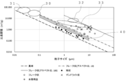
- Patent Documents 1 to 4 describe metal particles having protrusions radially protruding from the central portion, but as shown in FIG. 5, the silver particles of the present invention have a shape, an average particle size, and a specific surface area. The combination of surface areas is different.
- the silver particles according to the present invention have protrusions radially protruding from the central portion, have an average particle diameter (D) of 0.1 to 10 ⁇ m, and have a specific surface area (S) of 0.1 to 10 m 2 / g. It is assumed that the product of the true specific gravity ( ⁇ ) of the silver particles, the average particle size (D), and the specific surface area (S) is 12 or more and 24 or less.
- the silver particles can have a tap density of 2 to 4 g / cm 3 .
- the method for producing silver particles according to the present invention is a processing unit having a first processing surface and a second processing surface which are arranged so as to be close to each other and can be separated from each other and at least one of them rotates with respect to the other.
- a first treatment surface and a second treatment surface are used.
- a fluid to be treated, which is the liquid phase, is introduced between the two, and a force is generated by the pressure of the fluid to be treated to move the surface for treatment away from the surface for second treatment, and this force is generated.
- the treated fluid forms a thin film fluid, and the metal ions react with the reducing agent in the thin film fluid to obtain silver particles.
- the content of silver nitrate and the reducing agent in the fluid to be treated The ratio is 0.3 to 0.9 in terms of molar ratio (silver nitrate / reducing agent), the rotation speed of the processing unit is 2000 to 5000 rpm, and the back pressure in the processing unit is 0.005 to 0. It is assumed to be 0.05 MPa.
- the schematic diagram which shows the structure of the forced thin film reaction apparatus The schematic diagram which shows the processing part of the forced thin film reaction apparatus.
- An electron micrograph of silver particles obtained in Examples magnification: 20000 times.
- An electron micrograph of silver particles obtained in Examples magnification: 30,000 times).
- the silver particles according to an embodiment of the present invention have protrusions radially protruding from the central portion. .. Further, the average particle diameter (D) is 0.1 to 10 ⁇ m, the specific surface area (S) is 0.1 to 10 m 2 / g, and the true specific gravity ( ⁇ ) and the average particle diameter (D) of the silver particles are It is assumed that the product with the specific surface area (S) is 12 or more and 24 or less.
- the average particle size of the silver particles according to the present embodiment is not particularly limited as long as it is 0.1 to 10 ⁇ m, but when used for a conductive paste, for example, it should be 1 ⁇ m to 5 ⁇ m from the viewpoint of dispersibility and coatability. Is preferable. When it is 0.1 ⁇ m or more, good dispersibility is obtained, it is difficult to aggregate, and when it is 10 ⁇ m or less, it is easy to draw fine wiring.
- the average particle size in the present specification means the particle size (primary particle size) at an integrated value of 50% in the particle size distribution obtained by the laser diffraction / scattering method.
- the specific surface area of the silver particles according to the present embodiment is not particularly limited as long as it is 0.1 to 10 m 2 / g, but when used for a conductive paste, for example, it is 0.2 to 2 m from the viewpoint of contact area and conductivity. It is preferably 2 / g. When it is 0.1 m 2 / g or more, excellent conductivity can be easily obtained as compared with spherical silver particles, and when it is 10 m 2 / g or less, the problem of dendrite-like silver particles can be easily improved.
- the specific surface area as used herein means that the measurement sample is placed in a vacuum dryer, treated at room temperature for 2 hours, then the sample is filled so that the cells are dense, and then the BET specific surface area measuring device is used. After setting, pretreatment is performed at a degassing temperature of 40 ° C. for 60 minutes, and then the measured value is used.
- the shape of the silver particles according to this embodiment can be approximated to a stellation, and if a regular dodecahedron or a regular icosahedron is used as an approximate model, the specific surface area can be obtained by the following equations (1) and (2). be able to.
- the product of the true specific gravity ( ⁇ ), the average particle diameter (D), and the specific surface area (S) of the silver particles according to the present embodiment is 12 or more and 24 or less.
- the true specific gravity ( ⁇ ) of silver is 10.49 g / cm 3 .
- the specific surface area of the spherical and flake-shaped (when the plane shape is a perfect circle) silver particles can be obtained from the following equations (3) and (4) as theoretical values.
- Specific surface area (S) 6 / (true specific gravity ( ⁇ ) x average particle size (D)) ... (3)
- Specific surface area (S) 2 (aspect ratio +2) / (true specific gravity ( ⁇ ) x average particle size (D)) ... (4)
- the product of the true specific gravity ( ⁇ ) of the spherical silver particles, the average particle diameter (D), and the specific surface area (S) is 6. Since the product of the true specific gravity ( ⁇ ), the average particle diameter (D) and the specific surface area (S) is 12 or more and 24 or less, the silver particles according to the present embodiment are compared with the spherical silver particles having the same volume. It can be seen that it has a specific surface area of about 2 to 4 times. By using the silver particles according to the present embodiment in a conductive composition or the like, it is possible to improve the property of improving in proportion to the specific surface area.
- the contact area between the particles is increased to improve the conductivity, and the bonding interface with the resin to be blended is increased to increase the strength of the composition. It can be improved more than spherical silver particles.
- the product of the true specific gravity ( ⁇ ) of the flake-shaped silver particles, the average particle diameter (D), and the specific surface area (S) is 24 when the aspect ratio of the flake-shaped silver particles is 10 to 100. It is ⁇ 204, and it can be seen that it has a specific surface area of about 4 to 35 times that of the spherical silver particles having the same volume. Further, it was confirmed that the dendrite-like silver particles have a specific surface area about 10 to 30 times that of the spherical silver particles having the same volume from the measured values of the commercially available products measured in the examples described later.
- flake-shaped or dendrite-shaped silver particles in a conductive composition or the like, the property of improving in proportion to the specific surface area can be improved as compared with the spherical silver particles.
- the flake-shaped silver particles have a problem in terms of both dispersibility and conductivity, and the dendrite-shaped silver particles have a problem that they are not suitable for forming ultrafine lines or thin films.
- the specific surface area of the silver particles according to the present embodiment with respect to the same volume is larger than the true sphere and smaller than the flakes and dendrites, and the silver particles according to the present embodiment are true spheres, flakes, and dendrites. It has the characteristics of a well-balanced product. Specifically, the silver particles according to the present embodiment are excellent because they have protrusions that protrude radially from the center, so that adhesion between planes is unlikely to occur, and aggregation is difficult even without a surface treatment agent (lubricant). It is easy to obtain good dispersibility.
- the silver particles according to the present embodiment have protrusions that protrude radially from the central portion, excellent conductivity can be easily obtained due to the entanglement of the protrusions, and when the silver particles are crimped to the electric contacts, the surface of the electric contacts A so-called spike effect can also be obtained, which breaks through an insulating film such as a protective film or an oxide film and improves connection reliability with a conductive circuit.
- the silver particles according to the present embodiment have a shape different from the conventionally known dendrite-like shape.
- the silver particles according to the present embodiment have protrusions that protrude radially from the central portion, whereas in the dendrite shape, the protrusions that protrude from the particle surface are further branched from the main branch. It differs from the silver particles according to the present embodiment in that it has a dendritic shape that grows in a plane or three-dimensionally. Therefore, there is no problem that the breakage of the dendritic portion affects the conductivity as in the dendrite shape, and the problem that a gap is generated between the dendritic portions when mixed with the resin component does not occur. Further, from the relationship between the average particle size of the silver particles and the specific surface area according to the present embodiment, the protrusions can be adapted to the formation of ultrafine lines or thin films instead of the long overhanging shape like dendrites.
- the tap density of the silver particles according to the present embodiment is not particularly limited , but is preferably 2 to 4 g / cm 3 , and more preferably 2.5 to 3.5 g / cm 3 .
- the tap density is within the above range, voids are unlikely to occur when the conductive composition is produced, and volume shrinkage is unlikely to occur during drying or firing.
- Examples of the method for producing silver particles according to the present embodiment include a method of reacting silver nitrate with a reducing agent in a thin film fluid using a forced thin film reactor 1.
- a liquid A tank 10 for storing an aqueous solution containing a reducing agent (hereinafter, also referred to as liquid A) and a liquid A for adjusting the temperature of the liquid A are used.
- the inside of the liquid heat exchanger 11, the compressor (not shown) for sending air to the liquid A tank 10, the liquid B container 20 for storing the silver nitrate aqueous solution (hereinafter, also referred to as liquid B), and the liquid B container 20 are stirred.
- Examples thereof include a processing unit 3 for making a thin film fluid, and a rotation driving device 2 for relatively rotating the first processing unit 4 and the second processing unit 5 constituting the processing unit 3.
- Air is sent into the liquid A tank 10 by a compressor (not shown), and the pressure in the liquid A tank 10 rises, so that the liquid A is sent from the liquid A tank 10 to the heat exchanger 11 for the liquid A. After being adjusted in temperature, it is sent to the processing unit 3.
- the liquid feeding rate of the liquid A is not particularly limited, but is preferably 200 to 1000 ml / min, and more preferably 500 to 700 ml / min. When the liquid feeding rate is within the above range, silver particles having a desired average particle size and specific surface area can be easily obtained.
- the temperature of the liquid A is not particularly limited, but is preferably 10 to 40 ° C, more preferably 20 to 30 ° C. When the temperature of the liquid A is within the above range, silver particles having a desired average particle size and specific surface area can be easily obtained.
- liquid B In the liquid B container 20, silver nitrate is uniformly dispersed in the aqueous solution due to the rotation of the stirrer 21. Then, the B liquid is sent from the B liquid container 20 to the B liquid heat exchanger 23 to adjust the temperature by the B liquid pump 22, and then sent to the processing unit 3.
- the liquid feeding rate of the liquid B is not particularly limited, but is preferably 10 to 200 ml / min, and more preferably 50 to 150 ml / min. When the liquid feeding rate is within the above range, silver particles having a desired average particle size and specific surface area can be easily obtained.
- the temperature of the liquid B is not particularly limited, but is preferably 10 to 40 ° C, more preferably 20 to 30 ° C. When the temperature of the liquid B is within the above range, silver particles having a desired average particle size and specific surface area can be easily obtained.
- the processing unit 3 has a first processing unit 4 and a second processing unit 5 provided so as to be relatively close to each other and separated from each other.
- the first processing unit 4 and the second processing unit 5 have a first processing surface (not shown) and a second processing surface 5'opposing each other, respectively.
- the liquid A sent to the processing unit 3 is introduced into the first processing unit 4 between the first processing surface and the second processing surface 5'as shown by an arrow A.
- B for introducing the liquid A flow path 6 and the liquid B sent to the processing unit 3 between the first treatment surface and the second treatment surface 5'as shown by an arrow B.
- a liquid flow path 7 is provided.
- the reaction between silver nitrate and the reducing agent reduces the silver ions in the fluid to be treated, and silver particles are precipitated.
- the content ratio of silver nitrate and the reducing agent in the fluid to be treated is 0.3 to 0.9 in terms of molar ratio (silver nitrate / reducing agent), and is preferably 0.5 to 0.7.
- the rotation speed of the processing unit 3 is 2000 to 5000 rpm, preferably 3000 to 4000 rpm.
- the rotation speed is 2000 rpm or more, the fluid to be processed in the processing unit 3 is sufficiently agitated, and uniform particles are likely to be generated. Further, when the rotation speed is 5000 rpm or less, the fluid to be treated is unlikely to become hot due to frictional heat, and the target particles are likely to be generated.
- the back pressure in the processing unit 3 is 0.005 to 0.05 MPa, preferably 0.01 to 0.03 MPa.
- the back pressure means that the first treated portion 4 is separated from the first treated surface 5'when the fluid to be treated passes between the first treated portion 4 and the second treated portion 5. It is a pressure that is pressed from the back surface of the first processing portion 4 against the force that tries to spread in the direction.
- the back pressure is 0.005 MPa or more, the gap between the processing portions 3 does not become too wide and the desired stirring force can be easily obtained.
- the back pressure is 0.05 MPa or less, the fluid to be treated is used for processing. It is easy to flow into the part 3.
- the reducing agent is not particularly limited, but is, for example, sodium borohydride, sodium hypophosphate, hydrazine, transition metal element ions (trivalent titanium ion, divalent cobalt ion, etc.), methanol, ethanol, 2 -Alcohols such as propanol, reducing saccharides such as glucose and maltose, ascorbic acid, erythorbic acid and the like can be mentioned.
- a forced thin film reactor for example, those described in Patent Documents 5 and 6 can be used. Specifically, the forced thin film reactor "ULREA SS-11" manufactured by M-technique can be used. , Etc. can be used.
- Example 1 1 kg of L-ascorbic acid was dissolved in 10 L of water to prepare a 9.1 mass% L-ascorbic acid aqueous solution, which was used as a reaction solution A. Further, 1 kg of silver nitrate was dissolved in 2 L of water to prepare a 33 mass% silver nitrate aqueous solution, which was used as a reaction solution B.
- the reaction was carried out under the following conditions using a forced thin film reactor "ULREA SS-11" manufactured by M-technique. Specifically, the reaction solution A and the reaction solution B were mixed in a thin film fluid formed between the first treatment surface and the second treatment surface of the forced thin film reactor, and the obtained mixture was obtained. After allowing the liquid to stand for 1 hour, No. Using the filter paper of No. 5, the filter paper was separated and washed, and dried in a vacuum desiccator for 24 hours to obtain 550 g of silver particles (yield: about 85%).
- the particle size distribution, specific surface area, and tap density were measured by the following measuring methods.
- D50 Integrated value in the particle size distribution obtained by the laser diffraction / scattering method using a laser diffraction type particle size distribution measuring device ("MT3300EX II" manufactured by Microtrac Bell Co., Ltd., measuring medium: water). The particle size at 50% was defined as the average particle size.
- the measurement sample is placed in a vacuum dryer, treated at room temperature for 2 hours, and then the sample is filled so that the cells are dense, and then a BET specific surface area measuring device ("Gemini VII2390" manufactured by Shimadzu Corporation). ”), Then pretreatment was performed at a degassing temperature of 40 ° C. for 60 minutes, and then the measurement was performed.
- a BET specific surface area measuring device (“Gemini VII2390" manufactured by Shimadzu Corporation). ”)
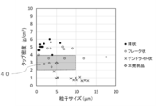
- the average particle size of the silver particles obtained in Example 1 was 4.97 ⁇ m, the specific surface area was 0.28 m 2 / g, and the tap density was 2.9 g / cm 3 , and the results are shown in the scatter plots of FIGS. Plotted. From these results, the product of the true specific gravity ( ⁇ ), the average particle size (D), and the specific surface area (S) was 14.6.
- the average particle size, specific surface area, and tap density of a plurality of commercially available spherical silver particles, flake-shaped silver particles, and dendrite-shaped silver particles were extracted from the catalog, and those not described were measured according to the above method.
- the results are shown in Table 1 and plotted in the scatter plots of FIGS. 5 and 6.
- the average particle size and specific surface area of the silver particles were extracted from the descriptions in Patent Documents 1 to 4, and the regions 30 to 33 to which the silver particles described in these documents belong are shown in the scatter plot of FIG.
- the theoretical values of the specific surface areas of the spherical silver particles and the flake-shaped silver particles obtained from the above formulas (3) and (4) are shown by dotted lines.
- the flake-shaped silver particles No. 13 belongs.
- flaky silver particles tend to adhere to each other, and in order to improve the dispersibility, it is necessary to use a large amount of surface treatment agent (lubricant), and the surface treatment agent inhibits conductivity. Therefore, there is a problem that it is difficult to achieve both dispersibility and conductivity. Therefore, the silver particles according to the present embodiment have different characteristics because they have a different shape from the flake-shaped silver particles.
- the spherical silver particle No. 2 belongs in the region 40. However, since the spherical silver particles do not have protrusions, they have characteristics different from those of the silver particles of the present embodiment, at least in terms of conductivity.
- the silver particles according to the present embodiment are different from the conventionally known spherical, flake-shaped, and dendrite-shaped silver particles in the combination of shape, average particle size, and specific surface area. You can see that.
Landscapes
- Chemical & Material Sciences (AREA)
- Chemical Kinetics & Catalysis (AREA)
- General Chemical & Material Sciences (AREA)
- Engineering & Computer Science (AREA)
- Nanotechnology (AREA)
- Manufacture Of Metal Powder And Suspensions Thereof (AREA)
- Powder Metallurgy (AREA)
Priority Applications (3)
| Application Number | Priority Date | Filing Date | Title |
|---|---|---|---|
| JP2022518599A JPWO2021220552A1 (https=) | 2020-04-28 | 2020-12-24 | |
| CN202080100248.9A CN115461172A (zh) | 2020-04-28 | 2020-12-24 | 银粒子 |
| KR1020227040248A KR20230002835A (ko) | 2020-04-28 | 2020-12-24 | 은 입자 |
Applications Claiming Priority (2)
| Application Number | Priority Date | Filing Date | Title |
|---|---|---|---|
| JP2020079775 | 2020-04-28 | ||
| JP2020-079775 | 2020-04-28 |
Publications (1)
| Publication Number | Publication Date |
|---|---|
| WO2021220552A1 true WO2021220552A1 (ja) | 2021-11-04 |
Family
ID=78331929
Family Applications (1)
| Application Number | Title | Priority Date | Filing Date |
|---|---|---|---|
| PCT/JP2020/048518 Ceased WO2021220552A1 (ja) | 2020-04-28 | 2020-12-24 | 銀粒子 |
Country Status (4)
| Country | Link |
|---|---|
| JP (1) | JPWO2021220552A1 (https=) |
| KR (1) | KR20230002835A (https=) |
| CN (1) | CN115461172A (https=) |
| WO (1) | WO2021220552A1 (https=) |
Cited By (3)
| Publication number | Priority date | Publication date | Assignee | Title |
|---|---|---|---|---|
| WO2022191001A1 (ja) * | 2021-03-10 | 2022-09-15 | Dowaエレクトロニクス株式会社 | 銀粉及びその製造方法 |
| JP2022140325A (ja) * | 2021-03-10 | 2022-09-26 | Dowaエレクトロニクス株式会社 | 銀粉及びその製造方法 |
| US12617013B2 (en) | 2021-03-10 | 2026-05-05 | Dowa Electronics Materials Co., Ltd. | Silver powder and method of producing same |
Citations (4)
| Publication number | Priority date | Publication date | Assignee | Title |
|---|---|---|---|---|
| WO2012014530A1 (ja) * | 2010-07-28 | 2012-02-02 | エム・テクニック株式会社 | 粒子径を制御された微粒子の製造方法 |
| WO2014041705A1 (ja) * | 2012-09-12 | 2014-03-20 | エム・テクニック株式会社 | 金属微粒子の製造方法 |
| WO2014042227A1 (ja) * | 2012-09-12 | 2014-03-20 | エム・テクニック株式会社 | 金属微粒子の製造方法 |
| JP2019183268A (ja) * | 2018-04-11 | 2019-10-24 | Dowaエレクトロニクス株式会社 | 銀粉およびその製造方法 |
Family Cites Families (10)
| Publication number | Priority date | Publication date | Assignee | Title |
|---|---|---|---|---|
| JP4803691B2 (ja) * | 2001-07-27 | 2011-10-26 | トッパン・フォームズ株式会社 | 導電ペースト |
| JP2005240092A (ja) * | 2004-02-26 | 2005-09-08 | Dowa Mining Co Ltd | 銀粉およびその製造方法 |
| WO2009008390A1 (ja) | 2007-07-06 | 2009-01-15 | M.Technique Co., Ltd. | 金属微粒子の製造方法及びその金属微粒子を含む金属コロイド溶液 |
| JP2009144196A (ja) | 2007-12-13 | 2009-07-02 | Hiroshima Univ | 金属粒子、金粒子の製造方法および光記録媒体 |
| JP5641385B2 (ja) | 2009-07-27 | 2014-12-17 | 独立行政法人物質・材料研究機構 | 樹枝状部分を有する金属ナノ粒子及びその製法 |
| JP5467831B2 (ja) * | 2009-09-24 | 2014-04-09 | Dowaエレクトロニクス株式会社 | 銀粉の製造方法 |
| JP5563329B2 (ja) | 2010-02-16 | 2014-07-30 | 株式会社新光化学工業所 | 金属ナノ粒子およびその製造方法 |
| JP5848711B2 (ja) | 2010-11-08 | 2016-01-27 | ナミックス株式会社 | 銀粒子の製造方法 |
| KR101515785B1 (ko) * | 2014-10-16 | 2015-05-04 | 덕산하이메탈(주) | 은 분말의 제조방법 |
| CN106825544A (zh) * | 2017-02-17 | 2017-06-13 | 江苏欧耐尔新型材料股份有限公司 | 提高太阳能电池电极导电性的高比表面积银粉及制备方法 |
-
2020
- 2020-12-24 JP JP2022518599A patent/JPWO2021220552A1/ja active Pending
- 2020-12-24 CN CN202080100248.9A patent/CN115461172A/zh active Pending
- 2020-12-24 WO PCT/JP2020/048518 patent/WO2021220552A1/ja not_active Ceased
- 2020-12-24 KR KR1020227040248A patent/KR20230002835A/ko active Pending
Patent Citations (4)
| Publication number | Priority date | Publication date | Assignee | Title |
|---|---|---|---|---|
| WO2012014530A1 (ja) * | 2010-07-28 | 2012-02-02 | エム・テクニック株式会社 | 粒子径を制御された微粒子の製造方法 |
| WO2014041705A1 (ja) * | 2012-09-12 | 2014-03-20 | エム・テクニック株式会社 | 金属微粒子の製造方法 |
| WO2014042227A1 (ja) * | 2012-09-12 | 2014-03-20 | エム・テクニック株式会社 | 金属微粒子の製造方法 |
| JP2019183268A (ja) * | 2018-04-11 | 2019-10-24 | Dowaエレクトロニクス株式会社 | 銀粉およびその製造方法 |
Cited By (6)
| Publication number | Priority date | Publication date | Assignee | Title |
|---|---|---|---|---|
| WO2022191001A1 (ja) * | 2021-03-10 | 2022-09-15 | Dowaエレクトロニクス株式会社 | 銀粉及びその製造方法 |
| JP2022140325A (ja) * | 2021-03-10 | 2022-09-26 | Dowaエレクトロニクス株式会社 | 銀粉及びその製造方法 |
| JP7185795B2 (ja) | 2021-03-10 | 2022-12-07 | Dowaエレクトロニクス株式会社 | 銀粉及びその製造方法 |
| JP2022186757A (ja) * | 2021-03-10 | 2022-12-15 | Dowaエレクトロニクス株式会社 | 銀粉 |
| JP7438305B2 (ja) | 2021-03-10 | 2024-02-26 | Dowaエレクトロニクス株式会社 | 銀粉 |
| US12617013B2 (en) | 2021-03-10 | 2026-05-05 | Dowa Electronics Materials Co., Ltd. | Silver powder and method of producing same |
Also Published As
| Publication number | Publication date |
|---|---|
| KR20230002835A (ko) | 2023-01-05 |
| CN115461172A (zh) | 2022-12-09 |
| JPWO2021220552A1 (https=) | 2021-11-04 |
Similar Documents
| Publication | Publication Date | Title |
|---|---|---|
| JP7329941B2 (ja) | コアシェル粒子およびその利用 | |
| US11767443B2 (en) | Copper particle mixture and method for manufacturing same, copper particle mixture dispersion, ink containing copper particle mixture, method for storing copper particle mixture, and method for sintering copper particle mixture | |
| WO2021220552A1 (ja) | 銀粒子 | |
| JP4178374B2 (ja) | 銀コートフレーク銅粉及びその銀コートフレーク銅粉の製造方法並びにその銀コートフレーク銅粉を用いた導電性ペースト | |
| JP7288133B1 (ja) | 銀粉及び銀粉の製造方法ならびに導電性ペースト | |
| JP2014201687A (ja) | 易変形性凝集体、熱伝導性樹脂組成物、熱伝導性部材、および熱伝導性接着シート | |
| CN114667311A (zh) | 导热填料及其制备方法 | |
| JP7075262B2 (ja) | コアシェル粒子およびその利用 | |
| JP2010180471A (ja) | フレーク状銀粉及びその製造方法、並びに導電性ペースト | |
| Jin et al. | The preparation of a core/shell structure with alumina coated spherical silica powder | |
| WO2023210663A1 (ja) | 球状銀粉、球状銀粉の製造方法、球状銀粉製造装置、及び導電性ペースト | |
| JP2011001205A (ja) | 多孔質シリカカプセルの製造方法 | |
| WO2020158185A1 (ja) | 被覆粒子、これを含む分散液および成型体、ならびにこれを用いて形成される焼結体 | |
| JP3932336B2 (ja) | 導電ペースト用銅粉の製造方法 | |
| JP4197110B2 (ja) | 混合銅粉、その混合銅粉の製造方法、その混合銅粉を用いた銅ペースト及びその銅ペーストを用いたプリント配線板 | |
| JP7398733B2 (ja) | 複合窒化アルミニウム粒子の製造方法、及び複合窒化アルミニウム粒子 | |
| JP4301646B2 (ja) | ニッケル粉の製造法 | |
| JP7670920B1 (ja) | 銀粉及び銀粉の製造方法、銀粉製造装置並びに樹脂硬化型導電性ペースト | |
| JP7670919B1 (ja) | 銀粉及び樹脂硬化型導電性ペースト | |
| JPH0784605B2 (ja) | 銅微粉末の製造方法 | |
| JP4233334B2 (ja) | 銅ペースト、及びその銅ペーストを用いたプリント配線板 | |
| JP2025179028A (ja) | 球状銀粉及び球状銀粉の製造方法、並びに導電性ペースト | |
| WO2025249331A1 (ja) | 球状銀粉及び球状銀粉の製造方法、並びに導電性ペースト | |
| KR20260053543A (ko) | 은분 및 은분의 제조 방법, 은분 제조 장치 그리고 수지 경화형 도전성 페이스트 | |
| JP4233333B2 (ja) | プリント配線板用の銅ペースト、及びその銅ペーストを用いたプリント配線板 |
Legal Events
| Date | Code | Title | Description |
|---|---|---|---|
| 121 | Ep: the epo has been informed by wipo that ep was designated in this application |
Ref document number: 20933129 Country of ref document: EP Kind code of ref document: A1 |
|
| ENP | Entry into the national phase |
Ref document number: 2022518599 Country of ref document: JP Kind code of ref document: A |
|
| ENP | Entry into the national phase |
Ref document number: 20227040248 Country of ref document: KR Kind code of ref document: A |
|
| NENP | Non-entry into the national phase |
Ref country code: DE |
|
| 122 | Ep: pct application non-entry in european phase |
Ref document number: 20933129 Country of ref document: EP Kind code of ref document: A1 |