WO2021215527A1 - 乗物用シート - Google Patents
乗物用シート Download PDFInfo
- Publication number
- WO2021215527A1 WO2021215527A1 PCT/JP2021/016410 JP2021016410W WO2021215527A1 WO 2021215527 A1 WO2021215527 A1 WO 2021215527A1 JP 2021016410 W JP2021016410 W JP 2021016410W WO 2021215527 A1 WO2021215527 A1 WO 2021215527A1
- Authority
- WO
- WIPO (PCT)
- Prior art keywords
- shock absorbing
- absorbing member
- seat cushion
- vehicle seat
- airbag
- Prior art date
- Legal status (The legal status is an assumption and is not a legal conclusion. Google has not performed a legal analysis and makes no representation as to the accuracy of the status listed.)
- Ceased
Links
Images


Classifications
-
- B—PERFORMING OPERATIONS; TRANSPORTING
- B60—VEHICLES IN GENERAL
- B60N—SEATS SPECIALLY ADAPTED FOR VEHICLES; VEHICLE PASSENGER ACCOMMODATION NOT OTHERWISE PROVIDED FOR
- B60N2/00—Seats specially adapted for vehicles; Arrangement or mounting of seats in vehicles
- B60N2/24—Seats specially adapted for vehicles; Arrangement or mounting of seats in vehicles for particular purposes or particular vehicles
- B60N2/42—Seats specially adapted for vehicles; Arrangement or mounting of seats in vehicles for particular purposes or particular vehicles the seat constructed to protect the occupant from the effect of abnormal g-forces, e.g. crash or safety seats
- B60N2/427—Seats or parts thereof displaced during a crash
-
- B—PERFORMING OPERATIONS; TRANSPORTING
- B60—VEHICLES IN GENERAL
- B60R—VEHICLES, VEHICLE FITTINGS, OR VEHICLE PARTS, NOT OTHERWISE PROVIDED FOR
- B60R21/00—Arrangements or fittings on vehicles for protecting or preventing injuries to occupants or pedestrians in case of accidents or other traffic risks
- B60R21/02—Occupant safety arrangements or fittings, e.g. crash pads
- B60R21/16—Inflatable occupant restraints or confinements designed to inflate upon impact or impending impact, e.g. air bags
- B60R21/20—Arrangements for storing inflatable members in their non-use or deflated condition; Arrangement or mounting of air bag modules or components
- B60R21/207—Arrangements for storing inflatable members in their non-use or deflated condition; Arrangement or mounting of air bag modules or components in vehicle seats
Definitions
- the present invention relates to a vehicle seat, and particularly relates to a vehicle seat capable of absorbing an impact applied to a seated person when an impact such as a collision occurs.
- a submarine phenomenon may occur in which the body of the occupant (occupant) seated on the seat slides forward and downward on the surface of the seat while being restrained by the seat belt. ..
- an airbag is provided between the seat cushion and the base plate, and a shock absorbing member is provided between the airbag and the seat cushion.
- Vehicle seats with an intervening occupant protection device are known.
- the airbag when a vehicle collides, the airbag expands and pushes up the seat cushion, compresses and hardens the seat cushion, suppresses the submarine phenomenon of the occupant, and the occupant strongly presses against the front part of the seat cushion. Even if the shock absorber is plastically deformed, the shock is absorbed.
- the present invention has been made in view of the above problems, and an object of the present invention is to appropriately absorb the impact generated on the seated person when an impact such as a collision occurs, and to suppress the increase in size of the seat cushion. Is to provide.
- the subject is a vehicle seat provided with a seat cushion, and the seat cushion is a seat cushion frame and a seat cushion pad placed on the seat cushion frame.
- a shock absorbing member provided below the seat cushion pad, and an airbag housed in a storage recess formed in the shock absorbing member, and the shock absorbing member is supported by a support member from below.
- the shock absorbing member is configured to be more easily deformed than the support member, which solves the problem.
- the airbag is housed in the storage recess of the shock absorbing member, it is possible to prevent the size of the seat cushion from becoming large in the vertical direction. Further, since the shock absorbing member is more easily deformed than the supporting member, the shock absorbing effect is stably exhibited. Further, the airbag is protected by being housed in the storage recess, and the assembling property to the shock absorbing member is improved.
- the storage recess of the shock absorbing member includes a front wall extending in the vertical direction and the width direction of the vehicle seat, and the front wall regulates the deployment direction of the airbag. good.
- the front wall makes it possible to easily control the forward deployment of the airbag.
- the storage recess of the shock absorbing member includes a rear wall extending in the vertical direction and the width direction of the vehicle seat, and the rear wall regulates the deployment direction of the airbag. good.
- the rear wall makes it possible to easily control the rearward deployment of the airbag.
- the storage recess of the shock absorbing member may be provided with a side wall in the width direction of the vehicle seat, and the side wall may regulate the deployment direction of the airbag.
- the side wall makes it possible to easily control the lateral deployment of the airbag.
- the shock absorbing member may be plastically deformed when a load equal to or larger than the deployed load of the airbag is input.
- the impact absorption is improved while suppressing the influence on the deployment of the airbag.
- the seat cushion pad may be covered with a skin member, and the shock absorbing member may include a skin fixing portion for fixing the skin member.
- the skin member since the skin member is fixed to the skin fixing portion of the shock absorbing member, the degree of freedom of setting is improved and the assembling property is improved.
- the end portion of the skin member is provided with a skin mounting portion to be attached to the skin fixing portion, and the skin mounting portion is fixed to the skin when the airbag is deployed. It is good to get out of the department.
- the skin attachment portion is detached from the skin fixing portion of the shock absorbing member when the airbag is deployed, the influence on the deployment of the airbag is suppressed, and the degree of freedom of setting in the deployment of the airbag is improved.
- the shock absorbing member may be provided adjacent to the sinking suppressing member that suppresses the sinking of the seated person.
- the shock absorbing member since the shock absorbing member is provided adjacent to the sinking suppressing member, the shock absorbing member can be easily positioned and the assembling property is improved.
- the seat cushion pad has a pad recess formed on the lower surface thereof, and a part of the upper surface of the shock absorbing member is housed in the pad recess.
- the shock absorbing member is provided with a frame mounting portion for mounting on the seat cushion frame.
- the shock absorbing member since the shock absorbing member is fixed to the seat cushion frame, the shock absorbing member can be easily positioned and the assembling property is improved.
- the airbag since the airbag is housed in the storage recess of the shock absorbing member, it is possible to prevent the size of the seat cushion from increasing in the vertical direction. Further, since the shock absorbing member is more easily deformed than the supporting member, the shock absorbing effect is stably exhibited. Further, the airbag is protected by being housed in the storage recess, and the assembling property to the shock absorbing member is improved. Further, according to the vehicle seat of the present invention, the front wall makes it possible to easily control the forward deployment of the airbag. Further, according to the vehicle seat of the present invention, it is possible to easily control the rearward deployment of the airbag by the rear wall.
- the lateral deployment of the airbag can be easily controlled by the side wall. Further, according to the vehicle seat of the present invention, in the above configuration, the impact absorption is improved while suppressing the influence on the deployment of the airbag. Further, according to the vehicle seat of the present invention, since the skin member is fixed to the skin fixing portion of the shock absorbing member, the degree of freedom of setting is improved and the assembling property is improved. Further, according to the vehicle seat of the present invention, since the skin mounting portion is separated from the skin fixing portion of the shock absorbing member when the airbag is deployed, the influence on the airbag deployment is suppressed, and the airbag is deployed. The degree of freedom of setting is improved.
- the shock absorbing member since the shock absorbing member is provided adjacent to the sinking suppressing member, the shock absorbing member can be easily positioned and the assembling property is improved. Further, according to the vehicle seat of the present invention, since the shock absorbing member is housed in the recess of the seat cushion pad, it is suppressed that a compressive load is applied to the seat cushion pad, and the shock absorbing member is assembled to the seat cushion pad. Improves sex. Further, according to the vehicle seat of the present invention, since the shock absorbing member is fixed to the seat cushion frame, the shock absorbing member can be easily positioned and the assembling property is improved.
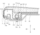
- FIG. 1 is a cross-sectional view taken along the line AA of FIG. 1 and is an explanatory view showing a structure around a shock absorbing member included in a vehicle seat according to the first embodiment of the present invention.
- FIG. 1 is a cross-sectional view taken along the line BB of FIG.
- FIG. 1 is a cross-sectional view taken along the line AA of FIG. 1 and is an explanatory view showing a structure around a shock absorbing member included in a vehicle seat according to the first embodiment of the present invention. It is external drawing of the vehicle seat which concerns on 2nd Embodiment of this invention. It is a schematic diagram which shows the seat cushion frame and the shock absorbing member in the vehicle seat which concerns on 2nd Embodiment of this invention.
- the vehicle seat according to the first and second embodiments of the present invention (hereinafter, the present embodiment) will be described with reference to FIGS. 1 to 13.
- a vehicle seat mounted on a vehicle will be described as an example, but the vehicle seat is limited to a vehicle seat mounted on a ground traveling vehicle having wheels such as an automobile or a railroad. It may be a seat mounted on an aircraft, a ship, or the like that moves other than the ground.
- each direction is defined as shown in FIG.
- the "front-rear direction” means the front-rear direction when viewed from the seated person of the vehicle seat, and is a direction that coincides with the traveling direction of the vehicle.
- the "seat width direction” means the width direction of the vehicle seat, and coincides with the left-right direction when viewed from the seated person of the vehicle seat.
- the “vertical direction” means the height direction of the vehicle seat, which coincides with the vertical direction when the vehicle seat is viewed from the front.
- the vehicle seat S according to the present embodiment has the appearance shown in FIG. In FIG. 1, a part of the vehicle seat S (specifically, the front end corner portion of the seat cushion S1) is shown in a configuration in which the trim cover S12 is removed for convenience of illustration.
- the seat cushion S1 is configured by placing the seat cushion pad S11 on the seat cushion frame F1 which is the skeleton, and further covering the seat cushion pad S11 with the trim cover S12.
- the seat back S2 is configured by placing a cushion pad (not shown) on the seat back frame F2 and covering it with the trim cover S12.
- the headrest S3 is formed by arranging a pad material (not shown) on a core material (not shown) and covering it with a trim cover S12.
- the seat cushion pad S11 of the seat cushion S1 and the seat back pad of the seat back S2 are urethane base materials molded by foam molding using a urethane foam material.
- the seat cushion frame F1 includes a pair of side frames 11 arranged apart from each other on the left and right, a pan frame 12 connecting the front ends of the pair of side frames 11, and a pair of side frames 11. It has a connecting pipe 13 that connects the rear end portions to each other, and these are formed in a frame shape that is integrally connected by welding or the like.
- the side frame 11 and the pan frame 12 are formed by pressing a metal plate or the like, and the connecting pipe 13 is formed of a metal pipe.
- the seat cushion frame F1 of the present embodiment has a submarine for suppressing a submarine phenomenon in which the body of a seated person seated on the vehicle seat S slides forward and downward when the vehicle collides forward.
- a pipe 14 is provided.
- the submarine pipe 14 is provided between the left and right side frames 11.
- a plurality of seat springs 15 as pressure receiving members are erected between the connecting pipe 13 of the seat cushion frame F1 and the submarine pipe 14. Specifically, three seat springs 15 are arranged side by side in the seat width direction, the front end of each seat spring 15 is hooked on the submarine pipe 14, and the rear end is hooked on the connecting pipe 13. It is erected in the front-rear direction of the seat (in other words, the direction orthogonal to the width direction of the seat).
- the seat cushion S1 of the vehicle seat S according to the first embodiment of the present invention includes a seat cushion frame F1, a seat cushion pad S11 mounted on the seat cushion frame F1, a shock absorbing member 20 provided below the seat cushion pad S11, and air. It has a bag module 30 and.
- shock absorbing member 20 As shown in FIGS. 3 to 5, the shock absorbing member 20 is provided below the seat cushion pad S11.
- the shock absorbing member 20 is provided with a storage recess 21 and a support recess 22 that are recessed downward from the upper surface.
- the inflator 31 and the airbag 32 of the airbag module 30, which will be described later, are housed in the storage recess 21 and the support recess 22.
- the storage recess 21 includes a front wall 21a and a rear wall 21b extending in the vertical direction and the seat width direction. Further, the storage recess 21 includes a bottom wall 21c extending in the front-rear direction and the seat width direction. Further, the storage recess 21 includes a pair of side walls 21d separated in the seat width direction, and the side walls 21d extend in the front-rear direction and the vertical direction.
- the shock absorbing member 20 is formed with an engaging recess 23a recessed upward in the front front end portion 23, and the engaging recess 23a is a hook attached to the trim front end portion S12a of the trim cover S12.
- the member F engages (FIG. 4).
- the shock absorbing member 20 is formed with a side end recess 24a recessed upward in the side end portion 24 forming the side surface, and the trim side end portion S12b of the trim cover S12 is formed in the side end recess 24a.
- the hook member F attached to the hook member F engages with the hook member F (FIG. 5).
- Airbag module 30 As shown in FIGS. 3 to 5, an airbag module 30 as an airbag device is arranged in the storage recess 21 and the support recess 22 of the shock absorbing member 20.
- the airbag module 30 is composed of a caseless airbag module having no module case.
- the airbag module 30 includes an inflator 31 and an airbag 32.
- the inflator 31 has a cylindrical shape, and is fixed to the shock absorbing member 20 and the seat cushion frame F1 by a bolt 31a extending downward from the outer peripheral portion of the inflator 31 and a nut 31b corresponding to the bolt 31a.
- the bolt 31a penetrates the bottom wall 21c of the storage recess 21 formed in the shock absorbing member 20 and the pan frame 12 which is a part of the seat cushion frame F1, and the nut 31b is attached to the tip thereof. Is fixed (FIGS. 4 and 5).
- the inflator 31 may be fixed to the shock absorbing member 20 and the seat cushion frame F1 by an inflator mounting member other than the bolt.
- the inflator 31 is a device that generates gas when an operation signal is input from a sensor (not shown) that detects a vehicle collision, and injects the generated gas into the airbag 32 to deploy the airbag 32. Inflate like.
- the airbag module 30 is configured to be caseless, but the present invention is not limited to this, and the airbag module 30 may be configured to include a module case.
- the shock absorbing member 20 is supported by the seat cushion frame F1 from below. More specifically, the shock absorbing member 20 is supported from below by the pan frame 12 below the seat cushion pad S11. The shock absorbing member 20 is configured to be more easily deformed than the pan frame 12 which is a supporting member.
- the shock absorbing member 20 may be configured to be crushed and shock absorbed when it exceeds a certain load value, and may be, for example, a resin blow-molded product having a hollow portion inside.
- the shock absorbing member 20 is not limited to the blow molded product, and has a hardness higher than that of the seat cushion pad S11 which is a urethane pad, and is crushed when a certain load value is exceeded to absorb the shock. It may be a urethane molded product provided with.
- the frame front end portion 12a of the pan frame 12 is received and arranged in the receiving recess 23b formed in front of the shock absorbing member 20.
- the frame side end portion 12b of the pan frame 12 is received and arranged in the side end recess 24a formed in the side end portion 24 of the shock absorbing member 20.
- the inflator 31 and the airbag 32 of the airbag module 30 are housed in a storage recess 21 and a support recess 22 as recesses formed in the shock absorbing member 20.
- the inflator 31 is housed in the storage recess 21, and a portion of the airbag 32 arranged behind the inflator 31 is placed on the support recess 22 (FIG. 4).
- the airbag module 30 has a recess (storage recess 21 and a support recess 22) of the shock absorbing member 20 provided below and a lower surface of the seat cushion pad S11 provided above. It will be placed between S11a.
- the airbag 32 inflated by the gas ejected from the inflator 31 pushes up the seat cushion pad S11 from its front end side over a predetermined area closer to the center, and the occupant seated on the seat cushion S1 moves forward. Suppress that.
- the buttocks or thighs of the occupant are strongly pressed against the seat cushion pad S11 pushed up by the expansion of the airbag 32, and are pressed against the seat cushion pad S11 and the shock absorbing member 20 arranged below the airbag 32.
- a pressure equal to or higher than a predetermined value is applied, the shock absorbing member 20 is plastically deformed so as to be crushed and the shock is absorbed. In this way, the load applied to the occupant at the time of a front collision is reduced.
- the airbag module 30 is housed in the storage recess 21 and the support recess 22 formed in the shock absorbing member 20, and the shock absorbing member 20 is formed from the pan frame 12 as the support member. Is also easily deformed.
- the airbag module 30 is housed in the recess of the shock absorbing member 20, so that the size of the seat cushion S1 in the vertical direction is prevented from increasing. Further, since the shock absorbing member 20 is more easily deformed than the pan frame 12 as a supporting member, the shock absorbing effect is stably exhibited. Further, the airbag module 30 is protected by being housed in the recess, and the assembling property of the airbag module 30 to the shock absorbing member 20 is also improved.
- the storage recess 21 is provided with a front wall 21a, and the front wall 21a regulates the deployment direction of the airbag 32, so that the deployment of the airbag 32 in the forward direction can be easily controlled. Further, in the storage recess 21, the rear wall 21b regulates the deployment direction of the airbag 32, so that the rearward deployment of the airbag 32 can be easily controlled. Further, the storage recess 21 is provided with a side wall 21d, and the side wall 21d regulates the deployment direction of the airbag 32, so that the lateral deployment of the airbag 32 can be easily controlled.
- the shock absorbing member 20 is configured to be plastically deformed when a load equal to or greater than the deployed load of the airbag 32 is input, the influence on the deployment of the airbag 32 is suppressed. , Impact absorption is improved.
- the seat cushion pad S11 is covered with a trim cover S12, and the shock absorbing member 20 is an engaging recess 23a or a side for fixing an end portion (trim front end portion S12a or trim side end portion S12b) of the trim cover S12. It is provided with an end recess 24a (skin fixing portion).
- the end portion of the trim cover S12 is fixed to the skin fixing portion of the shock absorbing member 20, the degree of freedom of setting is improved and the assembling property is improved.
- the trim front end portion S12a of the trim cover S12 is provided with a hooking member F (skin mounting portion) to be attached to the engaging recess 23a
- the trim side end portion S12b of the trim cover S12 is provided with a side end recess.
- a hook member F (skin attachment portion) to be attached to the 24a is provided.
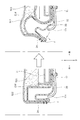
- the hooking member F is adapted to come off from the engaging recess 23a and the side end recess 24a when the airbag 32 is deployed (FIG. 6). More specifically, when the airbag 32 is deployed, the shock absorbing member 20 bends and collapses, so that the trim cover S12 comes off (specifically, outward in the seat width direction and upward in the seat vertical direction). ). In such a configuration, the influence on the deployment of the airbag 32 is suppressed, and the degree of freedom of setting in the deployment of the airbag 32 is improved.
- the shock absorbing member 20 is provided with a receiving recess 23b at the front end and a side end recess 24a at the side end as a frame mounting portion for mounting to the pan frame 12 constituting the seat cushion frame F1.
- a receiving recess 23b at the front end
- a side end recess 24a at the side end as a frame mounting portion for mounting to the pan frame 12 constituting the seat cushion frame F1.
- the shape and positional relationship of the shock absorbing member 20 are not limited.
- the support recess 22 is inclined rearward, and the pad recess 22 formed on the lower surface S11a of the seat cushion pad S11.
- a part of the upper surface of the shock absorbing member 20 may be housed in S11b.
- the shock absorbing member 20 is housed in the pad recess S11b, it is suppressed that a compressive load is applied to the seat cushion pad S11, and the assembling property of the shock absorbing member 20 to the seat cushion pad S11 is improved. ..
- the airbag 32 by arranging the airbag 32 on the inclined surface of the shock absorbing member 20, it is possible to suppress the forward movement of the occupant at the time of a front collision.
- the shock absorbing member 20 is provided adjacent to the submarine pipe 14 as a sinking suppressing member for suppressing the sinking of the seated person (FIG. 7), so that the shock absorbing member 20 can be easily positioned and can be assembled easily. Is improved.
- the shock absorbing member 20 is arranged directly above the submarine pipe 14 extending in the seat width direction, the load at the time of shock absorption is appropriately transmitted from the shock absorbing member 20 to the submarine pipe 14.
- Vehicle seat of the second embodiment The configuration of the vehicle seat S according to the second embodiment of the present invention will be described with reference to FIGS. 8 to 11. In the following description, the points common to the first embodiment will be omitted, and the differences will be mainly described.
- a rear seat for a vehicle mounted on a vehicle will be described as an example, but for a vehicle mounted on a ground traveling vehicle having wheels such as an automobile or a railroad.
- the seat is not limited to the rear seat, and may be a front seat for a vehicle, a second row seat of a three-row seat, or a seat mounted on an aircraft or a ship moving outside the ground.
- the shock absorbing member 20 is arranged between the pair of side frames 11 in the seat width direction and at a position avoiding the hanging portions T1 to T3 of the trim cover S12. ing.
- the shock absorbing member 20 has a first hanging portion T1 (right hanging portion) and a second hanging portion T2 (left hanging portion) in the seat width direction. It is arranged between the seats and in front of the third suspension portion T3 (rear suspension portion) in the front-rear direction of the seat. According to such a configuration, when the load at the time of shock absorption is transmitted to the shock absorbing member 20, the influence of the hanging portions T1 to T3 is suppressed.
- the lower surface 122 of the shock absorbing member 120 is supported from below by the seat cushion frame F1 and the vehicle body floor (supporting member).
- the support member that supports the shock absorbing member 120 is not particularly limited, and examples thereof include a frame member such as a pan frame 12 and a pressure receiving member such as a seat spring 15.
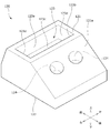
- the shock absorbing member 120 is provided with a first recess 123 as a storage recess between the upper surface 121 and the lower surface 122.
- the upper surface 121 of the shock absorbing member 120 is formed with an inclined surface 121a that is inclined downward toward the rear.
- a second recess 124 that is recessed downward is formed on the inclined surface 121a.
- the second recess 124 is provided as two cylindrical recesses separated in the seat width direction.
- the first recess 123 is recessed downward from the upper surface 121, and includes a front wall 123a and a rear wall 123b extending in the vertical direction and the seat width direction, and a bottom wall 123c extending in the front-rear direction and the seat width direction. , A pair of side walls 123d separated in the seat width direction are provided. The side wall 123d extends in the front-rear direction and the up-down direction.
- the number and shape of the second recess 124 is not limited to the example shown in FIG.
- the bottom surface of the second recess 124 extending in the sheet width direction may be provided as an oval recess.
- the airbag module 30 is housed in the first recess 123 so that the inflator 31 extends in the seat width direction. Then, a part of the upper surface 121 of the shock absorbing member 120 is housed in the pad recess S11b formed on the lower surface S11a of the seat cushion pad S11. At this time, it is preferable to arrange the airbag 32 on the inclined surface 121a of the shock absorbing member 120 because it is possible to suppress the forward movement of the occupant at the time of a front collision.
- FIG. 12 is a schematic cross-sectional view of the shock absorbing member 220 according to the modified example
- FIG. 13 is a schematic cross-sectional view showing the positional relationship between the shock absorbing member 220, the seat cushion pad S11, and the seat cushion frame F1.
- the shock absorbing member 220 is a blow-molded product made of resin, and the load value when it is crushed and shock absorption is performed is adjusted by appropriately setting the outer shape, the number and arrangement of the recesses (cavities). Is possible.
- the shock absorbing member 220 has a first recess 223a and a second recess 223b provided so that the upper surface 221 is an opening, and a third recess provided so that the lower surface 222 is an opening. It is provided with 224a and a fourth recess 224b.
- the first recess 223a, the second recess 223b, the third recess 224a, and the fourth recess 224b have a shape with rounded corners.
- the shock absorbing member 220 is arranged between the pair of side frames 11 in the seat width direction, similarly to the shock absorbing member 120 of FIG. That is, the first recess 223a and the third recess 224a are provided at positions in front of the seating portion of the occupant.
- the lower surface 222 of the shock absorbing member 220 is supported by a surface from the seat cushion frame F1 and the vehicle body floor (supporting member) from below.
- the airbag module 30 is housed in the first recess 223a and the third recess 224a so that the inflator 31 extends in the seat width direction.
- a part of the upper surface 221 of the shock absorbing member 220 is housed in the pad recess S11b formed on the lower surface S11a of the seat cushion pad S11.
- the vehicle seat according to the present embodiment has been described above by taking a vehicle seat as an example.
- the seat cushion according to the present embodiment is particularly used as long as it is a seat cushion of a seat that can cause an impact on the seated person, particularly a seat cushion of a seat that can sink into the lumbar region of the seated person when an impact is generated.
- the seat cushion of the present invention can also be used as a seat cushion for a vehicle seat used in a vehicle other than a vehicle.
Landscapes
- Engineering & Computer Science (AREA)
- Mechanical Engineering (AREA)
- Aviation & Aerospace Engineering (AREA)
- Transportation (AREA)
- Seats For Vehicles (AREA)
- Air Bags (AREA)
Applications Claiming Priority (2)
| Application Number | Priority Date | Filing Date | Title |
|---|---|---|---|
| JP2020-077744 | 2020-04-24 | ||
| JP2020077744A JP7549190B2 (ja) | 2020-04-24 | 2020-04-24 | 乗物用シート |
Publications (1)
| Publication Number | Publication Date |
|---|---|
| WO2021215527A1 true WO2021215527A1 (ja) | 2021-10-28 |
Family
ID=78269323
Family Applications (1)
| Application Number | Title | Priority Date | Filing Date |
|---|---|---|---|
| PCT/JP2021/016410 Ceased WO2021215527A1 (ja) | 2020-04-24 | 2021-04-23 | 乗物用シート |
Country Status (2)
| Country | Link |
|---|---|
| JP (3) | JP7549190B2 (https=) |
| WO (1) | WO2021215527A1 (https=) |
Citations (6)
| Publication number | Priority date | Publication date | Assignee | Title |
|---|---|---|---|---|
| JP2007276601A (ja) * | 2006-04-05 | 2007-10-25 | Takata Corp | 車両シート、車両、エアバッグモジュール |
| JP2008062792A (ja) * | 2006-09-07 | 2008-03-21 | Daihatsu Motor Co Ltd | 車両用シートクッション |
| JP2008114648A (ja) * | 2006-11-01 | 2008-05-22 | Nissan Motor Co Ltd | 側面衝突時の乗員保護装置 |
| JP2010047223A (ja) * | 2008-08-25 | 2010-03-04 | Toyoda Gosei Co Ltd | 乗員保護装置 |
| JP2010052535A (ja) * | 2008-08-27 | 2010-03-11 | Toyota Motor Corp | クッションエアバッグ装置を内蔵した車両用シート |
| JP2012106617A (ja) * | 2010-11-17 | 2012-06-07 | Ashimori Industry Co Ltd | エアバッグ装置を備えた車両用シート |
Family Cites Families (2)
| Publication number | Priority date | Publication date | Assignee | Title |
|---|---|---|---|---|
| JP2007118687A (ja) | 2005-10-26 | 2007-05-17 | Takata Corp | 乗員拘束装置 |
| JP2007290535A (ja) | 2006-04-25 | 2007-11-08 | Toyoda Gosei Co Ltd | 車両用シート |
-
2020
- 2020-04-24 JP JP2020077744A patent/JP7549190B2/ja active Active
-
2021
- 2021-04-23 WO PCT/JP2021/016410 patent/WO2021215527A1/ja not_active Ceased
-
2024
- 2024-08-28 JP JP2024146687A patent/JP7769255B2/ja active Active
-
2025
- 2025-03-26 JP JP2025052025A patent/JP2025092564A/ja active Pending
Patent Citations (6)
| Publication number | Priority date | Publication date | Assignee | Title |
|---|---|---|---|---|
| JP2007276601A (ja) * | 2006-04-05 | 2007-10-25 | Takata Corp | 車両シート、車両、エアバッグモジュール |
| JP2008062792A (ja) * | 2006-09-07 | 2008-03-21 | Daihatsu Motor Co Ltd | 車両用シートクッション |
| JP2008114648A (ja) * | 2006-11-01 | 2008-05-22 | Nissan Motor Co Ltd | 側面衝突時の乗員保護装置 |
| JP2010047223A (ja) * | 2008-08-25 | 2010-03-04 | Toyoda Gosei Co Ltd | 乗員保護装置 |
| JP2010052535A (ja) * | 2008-08-27 | 2010-03-11 | Toyota Motor Corp | クッションエアバッグ装置を内蔵した車両用シート |
| JP2012106617A (ja) * | 2010-11-17 | 2012-06-07 | Ashimori Industry Co Ltd | エアバッグ装置を備えた車両用シート |
Also Published As
| Publication number | Publication date |
|---|---|
| JP2021172234A (ja) | 2021-11-01 |
| JP7769255B2 (ja) | 2025-11-13 |
| JP7549190B2 (ja) | 2024-09-11 |
| JP2025092564A (ja) | 2025-06-19 |
| JP2024164233A (ja) | 2024-11-26 |
Similar Documents
| Publication | Publication Date | Title |
|---|---|---|
| JP7143684B2 (ja) | 車両用シート | |
| JP2011056979A (ja) | 車両のシート構造 | |
| JP5296747B2 (ja) | 車両用シート | |
| WO2020241810A1 (ja) | 乗物用シート | |
| WO2019035394A1 (ja) | 乗物用シート | |
| JP2024045684A (ja) | 乗物用シート | |
| JP2022179712A (ja) | 乗物用シート | |
| JP7239801B2 (ja) | 乗物用シート | |
| JP7529966B2 (ja) | 乗物用シート | |
| WO2021215527A1 (ja) | 乗物用シート | |
| JP5629205B2 (ja) | 乗物用シート | |
| JP6239850B2 (ja) | 乗物用シート | |
| JP2021120271A (ja) | 乗物用シート | |
| JP4503524B2 (ja) | エアバッグ装置の配設構造 | |
| JP7433015B2 (ja) | 乗物用シート | |
| JP7598017B2 (ja) | 乗物用シート | |
| JP7100240B2 (ja) | 乗物用シート | |
| JP2012171610A (ja) | 自動車用シート | |
| JP7382785B2 (ja) | 乗物用シート | |
| JP2005231422A (ja) | 衝撃吸収シート構造 | |
| JP5575304B2 (ja) | 車両用シート | |
| JP2006273065A (ja) | 腰部拘束用インフレータバッグ装置 | |
| JP2023171313A (ja) | 乗物用シート | |
| JP2025093310A (ja) | 乗物用シート | |
| JP5584611B2 (ja) | 乗物用シート |
Legal Events
| Date | Code | Title | Description |
|---|---|---|---|
| 121 | Ep: the epo has been informed by wipo that ep was designated in this application |
Ref document number: 21792471 Country of ref document: EP Kind code of ref document: A1 |
|
| NENP | Non-entry into the national phase |
Ref country code: DE |
|
| 122 | Ep: pct application non-entry in european phase |
Ref document number: 21792471 Country of ref document: EP Kind code of ref document: A1 |