WO2021215527A1 - 乗物用シート - Google Patents
乗物用シート Download PDFInfo
- Publication number
- WO2021215527A1 WO2021215527A1 PCT/JP2021/016410 JP2021016410W WO2021215527A1 WO 2021215527 A1 WO2021215527 A1 WO 2021215527A1 JP 2021016410 W JP2021016410 W JP 2021016410W WO 2021215527 A1 WO2021215527 A1 WO 2021215527A1
- Authority
- WO
- WIPO (PCT)
- Prior art keywords
- shock absorbing
- absorbing member
- seat cushion
- vehicle seat
- airbag
- Prior art date
Links
Images


Classifications
-
- B—PERFORMING OPERATIONS; TRANSPORTING
- B60—VEHICLES IN GENERAL
- B60N—SEATS SPECIALLY ADAPTED FOR VEHICLES; VEHICLE PASSENGER ACCOMMODATION NOT OTHERWISE PROVIDED FOR
- B60N2/00—Seats specially adapted for vehicles; Arrangement or mounting of seats in vehicles
- B60N2/24—Seats specially adapted for vehicles; Arrangement or mounting of seats in vehicles for particular purposes or particular vehicles
- B60N2/42—Seats specially adapted for vehicles; Arrangement or mounting of seats in vehicles for particular purposes or particular vehicles the seat constructed to protect the occupant from the effect of abnormal g-forces, e.g. crash or safety seats
- B60N2/427—Seats or parts thereof displaced during a crash
-
- B—PERFORMING OPERATIONS; TRANSPORTING
- B60—VEHICLES IN GENERAL
- B60R—VEHICLES, VEHICLE FITTINGS, OR VEHICLE PARTS, NOT OTHERWISE PROVIDED FOR
- B60R21/00—Arrangements or fittings on vehicles for protecting or preventing injuries to occupants or pedestrians in case of accidents or other traffic risks
- B60R21/02—Occupant safety arrangements or fittings, e.g. crash pads
- B60R21/16—Inflatable occupant restraints or confinements designed to inflate upon impact or impending impact, e.g. air bags
- B60R21/20—Arrangements for storing inflatable members in their non-use or deflated condition; Arrangement or mounting of air bag modules or components
- B60R21/207—Arrangements for storing inflatable members in their non-use or deflated condition; Arrangement or mounting of air bag modules or components in vehicle seats
Definitions
- the present invention relates to a vehicle seat, and particularly relates to a vehicle seat capable of absorbing an impact applied to a seated person when an impact such as a collision occurs.
- a submarine phenomenon may occur in which the body of the occupant (occupant) seated on the seat slides forward and downward on the surface of the seat while being restrained by the seat belt. ..
- an airbag is provided between the seat cushion and the base plate, and a shock absorbing member is provided between the airbag and the seat cushion.
- Vehicle seats with an intervening occupant protection device are known.
- the airbag when a vehicle collides, the airbag expands and pushes up the seat cushion, compresses and hardens the seat cushion, suppresses the submarine phenomenon of the occupant, and the occupant strongly presses against the front part of the seat cushion. Even if the shock absorber is plastically deformed, the shock is absorbed.
- the present invention has been made in view of the above problems, and an object of the present invention is to appropriately absorb the impact generated on the seated person when an impact such as a collision occurs, and to suppress the increase in size of the seat cushion. Is to provide.
- the subject is a vehicle seat provided with a seat cushion, and the seat cushion is a seat cushion frame and a seat cushion pad placed on the seat cushion frame.
- a shock absorbing member provided below the seat cushion pad, and an airbag housed in a storage recess formed in the shock absorbing member, and the shock absorbing member is supported by a support member from below.
- the shock absorbing member is configured to be more easily deformed than the support member, which solves the problem.
- the airbag is housed in the storage recess of the shock absorbing member, it is possible to prevent the size of the seat cushion from becoming large in the vertical direction. Further, since the shock absorbing member is more easily deformed than the supporting member, the shock absorbing effect is stably exhibited. Further, the airbag is protected by being housed in the storage recess, and the assembling property to the shock absorbing member is improved.
- the storage recess of the shock absorbing member includes a front wall extending in the vertical direction and the width direction of the vehicle seat, and the front wall regulates the deployment direction of the airbag. good.
- the front wall makes it possible to easily control the forward deployment of the airbag.
- the storage recess of the shock absorbing member includes a rear wall extending in the vertical direction and the width direction of the vehicle seat, and the rear wall regulates the deployment direction of the airbag. good.
- the rear wall makes it possible to easily control the rearward deployment of the airbag.
- the storage recess of the shock absorbing member may be provided with a side wall in the width direction of the vehicle seat, and the side wall may regulate the deployment direction of the airbag.
- the side wall makes it possible to easily control the lateral deployment of the airbag.
- the shock absorbing member may be plastically deformed when a load equal to or larger than the deployed load of the airbag is input.
- the impact absorption is improved while suppressing the influence on the deployment of the airbag.
- the seat cushion pad may be covered with a skin member, and the shock absorbing member may include a skin fixing portion for fixing the skin member.
- the skin member since the skin member is fixed to the skin fixing portion of the shock absorbing member, the degree of freedom of setting is improved and the assembling property is improved.
- the end portion of the skin member is provided with a skin mounting portion to be attached to the skin fixing portion, and the skin mounting portion is fixed to the skin when the airbag is deployed. It is good to get out of the department.
- the skin attachment portion is detached from the skin fixing portion of the shock absorbing member when the airbag is deployed, the influence on the deployment of the airbag is suppressed, and the degree of freedom of setting in the deployment of the airbag is improved.
- the shock absorbing member may be provided adjacent to the sinking suppressing member that suppresses the sinking of the seated person.
- the shock absorbing member since the shock absorbing member is provided adjacent to the sinking suppressing member, the shock absorbing member can be easily positioned and the assembling property is improved.
- the seat cushion pad has a pad recess formed on the lower surface thereof, and a part of the upper surface of the shock absorbing member is housed in the pad recess.
- the shock absorbing member is provided with a frame mounting portion for mounting on the seat cushion frame.
- the shock absorbing member since the shock absorbing member is fixed to the seat cushion frame, the shock absorbing member can be easily positioned and the assembling property is improved.
- the airbag since the airbag is housed in the storage recess of the shock absorbing member, it is possible to prevent the size of the seat cushion from increasing in the vertical direction. Further, since the shock absorbing member is more easily deformed than the supporting member, the shock absorbing effect is stably exhibited. Further, the airbag is protected by being housed in the storage recess, and the assembling property to the shock absorbing member is improved. Further, according to the vehicle seat of the present invention, the front wall makes it possible to easily control the forward deployment of the airbag. Further, according to the vehicle seat of the present invention, it is possible to easily control the rearward deployment of the airbag by the rear wall.
- the lateral deployment of the airbag can be easily controlled by the side wall. Further, according to the vehicle seat of the present invention, in the above configuration, the impact absorption is improved while suppressing the influence on the deployment of the airbag. Further, according to the vehicle seat of the present invention, since the skin member is fixed to the skin fixing portion of the shock absorbing member, the degree of freedom of setting is improved and the assembling property is improved. Further, according to the vehicle seat of the present invention, since the skin mounting portion is separated from the skin fixing portion of the shock absorbing member when the airbag is deployed, the influence on the airbag deployment is suppressed, and the airbag is deployed. The degree of freedom of setting is improved.
- the shock absorbing member since the shock absorbing member is provided adjacent to the sinking suppressing member, the shock absorbing member can be easily positioned and the assembling property is improved. Further, according to the vehicle seat of the present invention, since the shock absorbing member is housed in the recess of the seat cushion pad, it is suppressed that a compressive load is applied to the seat cushion pad, and the shock absorbing member is assembled to the seat cushion pad. Improves sex. Further, according to the vehicle seat of the present invention, since the shock absorbing member is fixed to the seat cushion frame, the shock absorbing member can be easily positioned and the assembling property is improved.
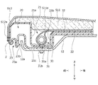
- FIG. 1 is a cross-sectional view taken along the line AA of FIG. 1 and is an explanatory view showing a structure around a shock absorbing member included in a vehicle seat according to the first embodiment of the present invention.
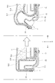
- FIG. 1 is a cross-sectional view taken along the line BB of FIG.
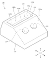
- FIG. 1 is a cross-sectional view taken along the line AA of FIG. 1 and is an explanatory view showing a structure around a shock absorbing member included in a vehicle seat according to the first embodiment of the present invention. It is external drawing of the vehicle seat which concerns on 2nd Embodiment of this invention. It is a schematic diagram which shows the seat cushion frame and the shock absorbing member in the vehicle seat which concerns on 2nd Embodiment of this invention.
- the vehicle seat according to the first and second embodiments of the present invention (hereinafter, the present embodiment) will be described with reference to FIGS. 1 to 13.
- a vehicle seat mounted on a vehicle will be described as an example, but the vehicle seat is limited to a vehicle seat mounted on a ground traveling vehicle having wheels such as an automobile or a railroad. It may be a seat mounted on an aircraft, a ship, or the like that moves other than the ground.
- each direction is defined as shown in FIG.
- the "front-rear direction” means the front-rear direction when viewed from the seated person of the vehicle seat, and is a direction that coincides with the traveling direction of the vehicle.
- the "seat width direction” means the width direction of the vehicle seat, and coincides with the left-right direction when viewed from the seated person of the vehicle seat.
- the “vertical direction” means the height direction of the vehicle seat, which coincides with the vertical direction when the vehicle seat is viewed from the front.
- the vehicle seat S according to the present embodiment has the appearance shown in FIG. In FIG. 1, a part of the vehicle seat S (specifically, the front end corner portion of the seat cushion S1) is shown in a configuration in which the trim cover S12 is removed for convenience of illustration.
- the seat cushion S1 is configured by placing the seat cushion pad S11 on the seat cushion frame F1 which is the skeleton, and further covering the seat cushion pad S11 with the trim cover S12.
- the seat back S2 is configured by placing a cushion pad (not shown) on the seat back frame F2 and covering it with the trim cover S12.
- the headrest S3 is formed by arranging a pad material (not shown) on a core material (not shown) and covering it with a trim cover S12.
- the seat cushion pad S11 of the seat cushion S1 and the seat back pad of the seat back S2 are urethane base materials molded by foam molding using a urethane foam material.
- the seat cushion frame F1 includes a pair of side frames 11 arranged apart from each other on the left and right, a pan frame 12 connecting the front ends of the pair of side frames 11, and a pair of side frames 11. It has a connecting pipe 13 that connects the rear end portions to each other, and these are formed in a frame shape that is integrally connected by welding or the like.
- the side frame 11 and the pan frame 12 are formed by pressing a metal plate or the like, and the connecting pipe 13 is formed of a metal pipe.
- the seat cushion frame F1 of the present embodiment has a submarine for suppressing a submarine phenomenon in which the body of a seated person seated on the vehicle seat S slides forward and downward when the vehicle collides forward.
- a pipe 14 is provided.
- the submarine pipe 14 is provided between the left and right side frames 11.
- a plurality of seat springs 15 as pressure receiving members are erected between the connecting pipe 13 of the seat cushion frame F1 and the submarine pipe 14. Specifically, three seat springs 15 are arranged side by side in the seat width direction, the front end of each seat spring 15 is hooked on the submarine pipe 14, and the rear end is hooked on the connecting pipe 13. It is erected in the front-rear direction of the seat (in other words, the direction orthogonal to the width direction of the seat).
- the seat cushion S1 of the vehicle seat S according to the first embodiment of the present invention includes a seat cushion frame F1, a seat cushion pad S11 mounted on the seat cushion frame F1, a shock absorbing member 20 provided below the seat cushion pad S11, and air. It has a bag module 30 and.
- shock absorbing member 20 As shown in FIGS. 3 to 5, the shock absorbing member 20 is provided below the seat cushion pad S11.
- the shock absorbing member 20 is provided with a storage recess 21 and a support recess 22 that are recessed downward from the upper surface.
- the inflator 31 and the airbag 32 of the airbag module 30, which will be described later, are housed in the storage recess 21 and the support recess 22.
- the storage recess 21 includes a front wall 21a and a rear wall 21b extending in the vertical direction and the seat width direction. Further, the storage recess 21 includes a bottom wall 21c extending in the front-rear direction and the seat width direction. Further, the storage recess 21 includes a pair of side walls 21d separated in the seat width direction, and the side walls 21d extend in the front-rear direction and the vertical direction.
- the shock absorbing member 20 is formed with an engaging recess 23a recessed upward in the front front end portion 23, and the engaging recess 23a is a hook attached to the trim front end portion S12a of the trim cover S12.
- the member F engages (FIG. 4).
- the shock absorbing member 20 is formed with a side end recess 24a recessed upward in the side end portion 24 forming the side surface, and the trim side end portion S12b of the trim cover S12 is formed in the side end recess 24a.
- the hook member F attached to the hook member F engages with the hook member F (FIG. 5).
- Airbag module 30 As shown in FIGS. 3 to 5, an airbag module 30 as an airbag device is arranged in the storage recess 21 and the support recess 22 of the shock absorbing member 20.
- the airbag module 30 is composed of a caseless airbag module having no module case.
- the airbag module 30 includes an inflator 31 and an airbag 32.
- the inflator 31 has a cylindrical shape, and is fixed to the shock absorbing member 20 and the seat cushion frame F1 by a bolt 31a extending downward from the outer peripheral portion of the inflator 31 and a nut 31b corresponding to the bolt 31a.
- the bolt 31a penetrates the bottom wall 21c of the storage recess 21 formed in the shock absorbing member 20 and the pan frame 12 which is a part of the seat cushion frame F1, and the nut 31b is attached to the tip thereof. Is fixed (FIGS. 4 and 5).
- the inflator 31 may be fixed to the shock absorbing member 20 and the seat cushion frame F1 by an inflator mounting member other than the bolt.
- the inflator 31 is a device that generates gas when an operation signal is input from a sensor (not shown) that detects a vehicle collision, and injects the generated gas into the airbag 32 to deploy the airbag 32. Inflate like.
- the airbag module 30 is configured to be caseless, but the present invention is not limited to this, and the airbag module 30 may be configured to include a module case.
- the shock absorbing member 20 is supported by the seat cushion frame F1 from below. More specifically, the shock absorbing member 20 is supported from below by the pan frame 12 below the seat cushion pad S11. The shock absorbing member 20 is configured to be more easily deformed than the pan frame 12 which is a supporting member.
- the shock absorbing member 20 may be configured to be crushed and shock absorbed when it exceeds a certain load value, and may be, for example, a resin blow-molded product having a hollow portion inside.
- the shock absorbing member 20 is not limited to the blow molded product, and has a hardness higher than that of the seat cushion pad S11 which is a urethane pad, and is crushed when a certain load value is exceeded to absorb the shock. It may be a urethane molded product provided with.
- the frame front end portion 12a of the pan frame 12 is received and arranged in the receiving recess 23b formed in front of the shock absorbing member 20.
- the frame side end portion 12b of the pan frame 12 is received and arranged in the side end recess 24a formed in the side end portion 24 of the shock absorbing member 20.
- the inflator 31 and the airbag 32 of the airbag module 30 are housed in a storage recess 21 and a support recess 22 as recesses formed in the shock absorbing member 20.
- the inflator 31 is housed in the storage recess 21, and a portion of the airbag 32 arranged behind the inflator 31 is placed on the support recess 22 (FIG. 4).
- the airbag module 30 has a recess (storage recess 21 and a support recess 22) of the shock absorbing member 20 provided below and a lower surface of the seat cushion pad S11 provided above. It will be placed between S11a.
- the airbag 32 inflated by the gas ejected from the inflator 31 pushes up the seat cushion pad S11 from its front end side over a predetermined area closer to the center, and the occupant seated on the seat cushion S1 moves forward. Suppress that.
- the buttocks or thighs of the occupant are strongly pressed against the seat cushion pad S11 pushed up by the expansion of the airbag 32, and are pressed against the seat cushion pad S11 and the shock absorbing member 20 arranged below the airbag 32.
- a pressure equal to or higher than a predetermined value is applied, the shock absorbing member 20 is plastically deformed so as to be crushed and the shock is absorbed. In this way, the load applied to the occupant at the time of a front collision is reduced.
- the airbag module 30 is housed in the storage recess 21 and the support recess 22 formed in the shock absorbing member 20, and the shock absorbing member 20 is formed from the pan frame 12 as the support member. Is also easily deformed.
- the airbag module 30 is housed in the recess of the shock absorbing member 20, so that the size of the seat cushion S1 in the vertical direction is prevented from increasing. Further, since the shock absorbing member 20 is more easily deformed than the pan frame 12 as a supporting member, the shock absorbing effect is stably exhibited. Further, the airbag module 30 is protected by being housed in the recess, and the assembling property of the airbag module 30 to the shock absorbing member 20 is also improved.
- the storage recess 21 is provided with a front wall 21a, and the front wall 21a regulates the deployment direction of the airbag 32, so that the deployment of the airbag 32 in the forward direction can be easily controlled. Further, in the storage recess 21, the rear wall 21b regulates the deployment direction of the airbag 32, so that the rearward deployment of the airbag 32 can be easily controlled. Further, the storage recess 21 is provided with a side wall 21d, and the side wall 21d regulates the deployment direction of the airbag 32, so that the lateral deployment of the airbag 32 can be easily controlled.
- the shock absorbing member 20 is configured to be plastically deformed when a load equal to or greater than the deployed load of the airbag 32 is input, the influence on the deployment of the airbag 32 is suppressed. , Impact absorption is improved.
- the seat cushion pad S11 is covered with a trim cover S12, and the shock absorbing member 20 is an engaging recess 23a or a side for fixing an end portion (trim front end portion S12a or trim side end portion S12b) of the trim cover S12. It is provided with an end recess 24a (skin fixing portion).
- the end portion of the trim cover S12 is fixed to the skin fixing portion of the shock absorbing member 20, the degree of freedom of setting is improved and the assembling property is improved.
- the trim front end portion S12a of the trim cover S12 is provided with a hooking member F (skin mounting portion) to be attached to the engaging recess 23a
- the trim side end portion S12b of the trim cover S12 is provided with a side end recess.
- a hook member F (skin attachment portion) to be attached to the 24a is provided.
- the hooking member F is adapted to come off from the engaging recess 23a and the side end recess 24a when the airbag 32 is deployed (FIG. 6). More specifically, when the airbag 32 is deployed, the shock absorbing member 20 bends and collapses, so that the trim cover S12 comes off (specifically, outward in the seat width direction and upward in the seat vertical direction). ). In such a configuration, the influence on the deployment of the airbag 32 is suppressed, and the degree of freedom of setting in the deployment of the airbag 32 is improved.
- the shock absorbing member 20 is provided with a receiving recess 23b at the front end and a side end recess 24a at the side end as a frame mounting portion for mounting to the pan frame 12 constituting the seat cushion frame F1.
- a receiving recess 23b at the front end
- a side end recess 24a at the side end as a frame mounting portion for mounting to the pan frame 12 constituting the seat cushion frame F1.
- the shape and positional relationship of the shock absorbing member 20 are not limited.
- the support recess 22 is inclined rearward, and the pad recess 22 formed on the lower surface S11a of the seat cushion pad S11.
- a part of the upper surface of the shock absorbing member 20 may be housed in S11b.
- the shock absorbing member 20 is housed in the pad recess S11b, it is suppressed that a compressive load is applied to the seat cushion pad S11, and the assembling property of the shock absorbing member 20 to the seat cushion pad S11 is improved. ..
- the airbag 32 by arranging the airbag 32 on the inclined surface of the shock absorbing member 20, it is possible to suppress the forward movement of the occupant at the time of a front collision.
- the shock absorbing member 20 is provided adjacent to the submarine pipe 14 as a sinking suppressing member for suppressing the sinking of the seated person (FIG. 7), so that the shock absorbing member 20 can be easily positioned and can be assembled easily. Is improved.
- the shock absorbing member 20 is arranged directly above the submarine pipe 14 extending in the seat width direction, the load at the time of shock absorption is appropriately transmitted from the shock absorbing member 20 to the submarine pipe 14.
- Vehicle seat of the second embodiment The configuration of the vehicle seat S according to the second embodiment of the present invention will be described with reference to FIGS. 8 to 11. In the following description, the points common to the first embodiment will be omitted, and the differences will be mainly described.
- a rear seat for a vehicle mounted on a vehicle will be described as an example, but for a vehicle mounted on a ground traveling vehicle having wheels such as an automobile or a railroad.
- the seat is not limited to the rear seat, and may be a front seat for a vehicle, a second row seat of a three-row seat, or a seat mounted on an aircraft or a ship moving outside the ground.
- the shock absorbing member 20 is arranged between the pair of side frames 11 in the seat width direction and at a position avoiding the hanging portions T1 to T3 of the trim cover S12. ing.
- the shock absorbing member 20 has a first hanging portion T1 (right hanging portion) and a second hanging portion T2 (left hanging portion) in the seat width direction. It is arranged between the seats and in front of the third suspension portion T3 (rear suspension portion) in the front-rear direction of the seat. According to such a configuration, when the load at the time of shock absorption is transmitted to the shock absorbing member 20, the influence of the hanging portions T1 to T3 is suppressed.
- the lower surface 122 of the shock absorbing member 120 is supported from below by the seat cushion frame F1 and the vehicle body floor (supporting member).
- the support member that supports the shock absorbing member 120 is not particularly limited, and examples thereof include a frame member such as a pan frame 12 and a pressure receiving member such as a seat spring 15.
- the shock absorbing member 120 is provided with a first recess 123 as a storage recess between the upper surface 121 and the lower surface 122.
- the upper surface 121 of the shock absorbing member 120 is formed with an inclined surface 121a that is inclined downward toward the rear.
- a second recess 124 that is recessed downward is formed on the inclined surface 121a.
- the second recess 124 is provided as two cylindrical recesses separated in the seat width direction.
- the first recess 123 is recessed downward from the upper surface 121, and includes a front wall 123a and a rear wall 123b extending in the vertical direction and the seat width direction, and a bottom wall 123c extending in the front-rear direction and the seat width direction. , A pair of side walls 123d separated in the seat width direction are provided. The side wall 123d extends in the front-rear direction and the up-down direction.
- the number and shape of the second recess 124 is not limited to the example shown in FIG.
- the bottom surface of the second recess 124 extending in the sheet width direction may be provided as an oval recess.
- the airbag module 30 is housed in the first recess 123 so that the inflator 31 extends in the seat width direction. Then, a part of the upper surface 121 of the shock absorbing member 120 is housed in the pad recess S11b formed on the lower surface S11a of the seat cushion pad S11. At this time, it is preferable to arrange the airbag 32 on the inclined surface 121a of the shock absorbing member 120 because it is possible to suppress the forward movement of the occupant at the time of a front collision.
- FIG. 12 is a schematic cross-sectional view of the shock absorbing member 220 according to the modified example
- FIG. 13 is a schematic cross-sectional view showing the positional relationship between the shock absorbing member 220, the seat cushion pad S11, and the seat cushion frame F1.
- the shock absorbing member 220 is a blow-molded product made of resin, and the load value when it is crushed and shock absorption is performed is adjusted by appropriately setting the outer shape, the number and arrangement of the recesses (cavities). Is possible.
- the shock absorbing member 220 has a first recess 223a and a second recess 223b provided so that the upper surface 221 is an opening, and a third recess provided so that the lower surface 222 is an opening. It is provided with 224a and a fourth recess 224b.
- the first recess 223a, the second recess 223b, the third recess 224a, and the fourth recess 224b have a shape with rounded corners.
- the shock absorbing member 220 is arranged between the pair of side frames 11 in the seat width direction, similarly to the shock absorbing member 120 of FIG. That is, the first recess 223a and the third recess 224a are provided at positions in front of the seating portion of the occupant.
- the lower surface 222 of the shock absorbing member 220 is supported by a surface from the seat cushion frame F1 and the vehicle body floor (supporting member) from below.
- the airbag module 30 is housed in the first recess 223a and the third recess 224a so that the inflator 31 extends in the seat width direction.
- a part of the upper surface 221 of the shock absorbing member 220 is housed in the pad recess S11b formed on the lower surface S11a of the seat cushion pad S11.
- the vehicle seat according to the present embodiment has been described above by taking a vehicle seat as an example.
- the seat cushion according to the present embodiment is particularly used as long as it is a seat cushion of a seat that can cause an impact on the seated person, particularly a seat cushion of a seat that can sink into the lumbar region of the seated person when an impact is generated.
- the seat cushion of the present invention can also be used as a seat cushion for a vehicle seat used in a vehicle other than a vehicle.
Landscapes
- Engineering & Computer Science (AREA)
- Mechanical Engineering (AREA)
- Aviation & Aerospace Engineering (AREA)
- Transportation (AREA)
- Seats For Vehicles (AREA)
- Air Bags (AREA)
Abstract
衝突などの衝撃発生時に着座者に生じる衝撃を適切に吸収しつつ、シートクッションの大型化が抑制された乗物用シートの提供。 シートクッション(S1)を備えた乗物用シート(S)であって、シートクッション(S1)は、シートクッションフレーム(F1)と、シートクッションフレーム(F1)の上に載置されたシートクッションパッド(S1)と、シートクッションパッド(S11)の下方に設けられた衝撃吸収部材(20)と、衝撃吸収部材(20)に形成された収納凹部(21)に収容されたエアバッグ(30)と、を有し、衝撃吸収部材(20)は下方から支持部材としてのパンフレーム(12)によって支持されており、衝撃吸収部材(20)は、パンフレーム(12)よりも変形し易く構成されている。
Description
本発明は、乗物用シートに係り、特に衝突などの衝撃発生時に着座者に加わる衝撃を吸収することが可能な乗物用シートに関する。
走行中の車両が前突した際には、シートに着座した着座者(乗員)の体が、シートベルトに拘束された状態でシートの表面上を前下方に滑り落ちるサブマリン現象が発生することがある。サブマリン現象を抑制するための対策としては、例えば特許文献1に記載されているように、シートクッションと、ベースプレートとの間にエアバッグを設け、エアバッグとシートクッションとの間に衝撃吸収部材が介在された乗員保護装置を備えた車両用シートが知られている。
特許文献1の車両用シートでは、車両衝突時に、エアバッグが膨張してシートクッションを押し上げ、シートクッションを圧縮硬化させ、乗員のサブマリン現象を抑制するとともに、乗員がシートクッションの前部に強く押し付けられても、衝撃吸収材が塑性変形して衝撃が吸収される。
特許文献1に記載の車両用シートでは、エアバッグと衝撃吸収部材が上下方向に重なって配置されているため、シートクッションの上下方向におけるサイズが大きくなっていた。
本発明は、上記の課題に鑑みてなされたものであり、その目的は、衝突などの衝撃発生時に着座者に生じる衝撃を適切に吸収しつつ、シートクッションの大型化が抑制された乗物用シートを提供することにある。
前記課題は、本発明の乗物用シートによれば、シートクッションを備えた乗物用シートであって、前記シートクッションは、シートクッションフレームと、前記シートクッションフレームの上に載置されたシートクッションパッドと、前記シートクッションパッドの下方に設けられた衝撃吸収部材と、前記衝撃吸収部材に形成された収納凹部に収容されたエアバッグと、を有し、前記衝撃吸収部材は下方から支持部材によって支持されており、前記衝撃吸収部材は、前記支持部材よりも変形し易く構成されていることにより解決される。
上記のように構成された本発明の乗物用シートでは、エアバッグが衝撃吸収部材の収納凹部に収納されていることで、シートクッションの上下方向におけるサイズが大きくなってしまうことが抑制される。また、衝撃吸収部材が、支持部材よりも変形し易いため、衝撃吸収効果が安定して発揮される。さらに、エアバッグが収納凹部に収容されることで保護され、衝撃吸収部材に対する組付性も向上する。
また、上記の構成において、前記衝撃吸収部材の前記収納凹部は、前記乗物用シートの上下方向及び幅方向に延在する前壁を備え、前記前壁は、前記エアバッグの展開方向を規制するとよい。
上記の構成では、前壁によりエアバッグの前方への展開を簡易に制御することが可能となる。
上記の構成では、前壁によりエアバッグの前方への展開を簡易に制御することが可能となる。
また、上記の構成において、前記衝撃吸収部材の前記収納凹部は、前記乗物用シートの上下方向及び幅方向に延在する後壁を備え、前記後壁は、前記エアバッグの展開方向を規制するとよい。
上記の構成では、後壁によりエアバッグの後方への展開を簡易に制御することが可能となる。
上記の構成では、後壁によりエアバッグの後方への展開を簡易に制御することが可能となる。
また、上記の構成において、前記衝撃吸収部材の前記収納凹部は、前記乗物用シートの幅方向に側壁を備え、前記側壁は、前記エアバッグの展開方向を規制するとよい。
上記の構成では、側壁によりエアバッグの側方への展開を簡易に制御することが可能となる。
上記の構成では、側壁によりエアバッグの側方への展開を簡易に制御することが可能となる。
また、上記の構成において、前記衝撃吸収部材は、前記エアバッグの展開荷重以上の荷重入力時に塑性変形するとよい。
上記の構成では、エアバッグが展開することへの影響を抑制しつつ、衝撃吸収性が向上する。
上記の構成では、エアバッグが展開することへの影響を抑制しつつ、衝撃吸収性が向上する。
また、上記の構成において、前記シートクッションパッドは、表皮部材に覆われており、前記衝撃吸収部材は、前記表皮部材を固定するための表皮固定部を備えているとよい。
上記の構成では、衝撃吸収部材の表皮固定部に、表皮部材が固定されるため、設定自由度が向上し組付性が向上する。
上記の構成では、衝撃吸収部材の表皮固定部に、表皮部材が固定されるため、設定自由度が向上し組付性が向上する。
また、上記の構成において、前記表皮部材の端部には、前記表皮固定部に取付けられる表皮取付部が設けられており、前記表皮取付部は、前記エアバッグが展開する際に、前記表皮固定部から外れるとよい。
上記の構成では、エアバッグの展開時に表皮取付部が衝撃吸収部材の表皮固定部から外れるため、エアバッグが展開することへの影響が抑制され、エアバッグの展開における設定自由度が向上する。
上記の構成では、エアバッグの展開時に表皮取付部が衝撃吸収部材の表皮固定部から外れるため、エアバッグが展開することへの影響が抑制され、エアバッグの展開における設定自由度が向上する。
また、上記の構成において、前記衝撃吸収部材は、着座者の沈み込みを抑制する沈み込み抑制部材に隣接して設けられているとよい。
上記の構成では、衝撃吸収部材が、沈み込み抑制部材に隣接して設けられるため、衝撃吸収部材の位置決めが容易となり組付性が向上する。
上記の構成では、衝撃吸収部材が、沈み込み抑制部材に隣接して設けられるため、衝撃吸収部材の位置決めが容易となり組付性が向上する。
また、前記シートクッションパッドは、下面にパッド凹部が形成されており、前記衝撃吸収部材は、上面の一部が、前記パッド凹部に収納される。
上記の構成では、シートクッションパッドの凹部に衝撃吸収部材が収納されるため、シートクッションパッドに圧縮荷重がかかることが抑制され、シートクッションパッドに対する衝撃吸収部材の組付性が向上する。
上記の構成では、シートクッションパッドの凹部に衝撃吸収部材が収納されるため、シートクッションパッドに圧縮荷重がかかることが抑制され、シートクッションパッドに対する衝撃吸収部材の組付性が向上する。
また、上記の構成において、前記衝撃吸収部材には、前記シートクッションフレームに取付けるためのフレーム取付部が設けられているとよい。
上記の構成では、衝撃吸収部材が、シートクッションフレームに固定されるため、衝撃吸収部材の位置決めが容易となり組付性が向上する。
上記の構成では、衝撃吸収部材が、シートクッションフレームに固定されるため、衝撃吸収部材の位置決めが容易となり組付性が向上する。
本発明の乗物用シートによれば、エアバッグが衝撃吸収部材の収納凹部に収納されていることで、シートクッションの上下方向におけるサイズが大きくなってしまうことが抑制される。また、衝撃吸収部材が、支持部材よりも変形し易いため、衝撃吸収効果が安定して発揮される。さらに、エアバッグが収納凹部に収容されることで保護され、衝撃吸収部材に対する組付性も向上する。
また、本発明の乗物用シートによれば、前壁によりエアバッグの前方への展開を簡易に制御することが可能となる。
また、本発明の乗物用シートによれば、後壁によりエアバッグの後方への展開を簡易に制御することが可能となる。
また、本発明の乗物用シートによれば、側壁によりエアバッグの側方への展開を簡易に制御することが可能となる。
また、本発明の乗物用シートによれば、上記の構成では、エアバッグが展開することへの影響を抑制しつつ、衝撃吸収性が向上する。
また、本発明の乗物用シートによれば、衝撃吸収部材の表皮固定部に、表皮部材が固定されるため、設定自由度が向上し組付性が向上する。
また、本発明の乗物用シートによれば、エアバッグの展開時に表皮取付部が衝撃吸収部材の表皮固定部から外れるため、エアバッグが展開することへの影響が抑制され、エアバッグの展開における設定自由度が向上する。
また、本発明の乗物用シートによれば、衝撃吸収部材が、沈み込み抑制部材に隣接して設けられるため、衝撃吸収部材の位置決めが容易となり組付性が向上する。
また、本発明の乗物用シートによれば、シートクッションパッドの凹部に衝撃吸収部材が収納されるため、シートクッションパッドに圧縮荷重がかかることが抑制され、シートクッションパッドに対する衝撃吸収部材の組付性が向上する。
また、本発明の乗物用シートによれば、衝撃吸収部材が、シートクッションフレームに固定されるため、衝撃吸収部材の位置決めが容易となり組付性が向上する。
以下、図1乃至図13を参照しながら、本発明の第一及び第二の実施形態(以下、本実施形態)に係る乗物用シートについて説明する。本実施形態に係る乗物用シートとして、車両に搭載される車両用シートを例に挙げて説明することとするが、自動車・鉄道など車輪を有する地上走行用乗物に搭載される車両用シートに限定されるものではなく、地上以外を移動する航空機や船舶などに搭載されるシートであってもよい。
なお、以下に説明する実施形態は、本発明の理解を容易にするための一例に過ぎず、本発明を限定するものではない。すなわち、以下に説明する部材の形状、寸法、配置等については、本発明の趣旨を逸脱することなく、変更、改良され得るとともに、本発明にはその等価物が含まれることは勿論である。
本明細書における方向を示す用語に関し、図1のように各方向を定義する。具体的には、以下の説明中、「前後方向」とは、車両用シートの着座者から見たときの前後方向を意味し、車両の走行方向と一致する方向である。「シート幅方向」とは、車両用シートの横幅方向を意味し、車両用シートの着座者から見たときの左右方向と一致する。また、「上下方向」とは、車両用シートの高さ方向を意味し、車両用シートを正面から見たときの上下方向と一致している。
[1.車両用シートSの構成]
本実施形態に係る車両用シートSは、図1に図示した外観を有している。なお、図1中、車両用シートSの一部(具体的には、シートクッションS1の前端角部)については、図示の都合上、トリムカバーS12を外した構成にて図示している。
本実施形態に係る車両用シートSは、図1に図示した外観を有している。なお、図1中、車両用シートSの一部(具体的には、シートクッションS1の前端角部)については、図示の都合上、トリムカバーS12を外した構成にて図示している。
車両用シートSは、着座者の臀部を支える着座部分となるシートクッションS1、着座者の背部を支える背もたれ部分となるシートバックS2、及び、シートバックS2の上部に配され、着座者の頭部を支えるヘッドレストS3を主な構成要素として有する。図2に示されるように、車両用シートSは、シートクッションフレームF1及びシートバックフレームF2を主構成要素とするシートフレームFを骨格として有している。
シートクッションS1は、骨格となるシートクッションフレームF1に、シートクッションパッドS11を載置し、更にシートクッションパッドS11をトリムカバーS12で覆うことで構成されている。シートバックS2はシートバックフレームF2に不図示のクッションパッドを載置して、トリムカバーS12で覆うことで構成されている。ヘッドレストS3は、不図示の芯材に不図示のパッド材を配して、トリムカバーS12で被覆して形成されている。シートクッションS1のシートクッションパッドS11やシートバックS2のシートバックパッドはウレタン発泡材を用いて、発泡成型により成型されたウレタン基材である。
(シートクッションフレームF1)
図2に示すように、シートクッションフレームF1は、左右に離間して配置された一対のサイドフレーム11と、一対のサイドフレーム11の前端部同士を連結するパンフレーム12と、一対のサイドフレーム11の後端部同士を連結する連結パイプ13とを有し、これらが溶接などによって一体に結合された枠状に形成されている。サイドフレーム11およびパンフレーム12は、金属板をプレス加工するなどして形成され、連結パイプ13は、金属パイプから形成されている。
図2に示すように、シートクッションフレームF1は、左右に離間して配置された一対のサイドフレーム11と、一対のサイドフレーム11の前端部同士を連結するパンフレーム12と、一対のサイドフレーム11の後端部同士を連結する連結パイプ13とを有し、これらが溶接などによって一体に結合された枠状に形成されている。サイドフレーム11およびパンフレーム12は、金属板をプレス加工するなどして形成され、連結パイプ13は、金属パイプから形成されている。
図2に示すように、本実施形態のシートクッションフレームF1には、車両が前突した際に、車両用シートSに着座した着座者の体が前下方に滑り落ちるサブマリン現象を抑制するためのサブマリンパイプ14が設けられている。サブマリンパイプ14は、左右のサイドフレーム11の間に設けられている。
また、シートクッションフレームF1の連結パイプ13とサブマリンパイプ14の間には、受圧部材としての複数のシートスプリング15が架設されている。具体的には、3本のシートスプリング15がシート幅方向に並んで配置されており、各シートスプリング15の前端がサブマリンパイプ14に掛止され、後端が連結パイプ13に掛止されることで、シート前後方向(換言するとシート幅方向と直交する方向)に架設されている。
[2.第一実施形態のシートクッション]
図2乃至図7を参照しながら、本発明の第一実施形態に係る車両用シートSのシートクッションS1の構成について詳細に説明する。本実施形態に係るシートクッションS1は、シートクッションフレームF1と、シートクッションフレームF1の上に載置されたシートクッションパッドS11と、シートクッションパッドS11の下方に設けられた衝撃吸収部材20と、エアバッグモジュール30と、を有している。
図2乃至図7を参照しながら、本発明の第一実施形態に係る車両用シートSのシートクッションS1の構成について詳細に説明する。本実施形態に係るシートクッションS1は、シートクッションフレームF1と、シートクッションフレームF1の上に載置されたシートクッションパッドS11と、シートクッションパッドS11の下方に設けられた衝撃吸収部材20と、エアバッグモジュール30と、を有している。
(衝撃吸収部材20)
図3乃至図5に示されるように、衝撃吸収部材20は、シートクッションパッドS11の下方に設けられている。衝撃吸収部材20には、上面から下方に向かって窪んだ収納凹部21及び支持凹部22が設けられている。収納凹部21及び支持凹部22には、後述するエアバッグモジュール30のインフレータ31及びエアバッグ32が収納される。
図3乃至図5に示されるように、衝撃吸収部材20は、シートクッションパッドS11の下方に設けられている。衝撃吸収部材20には、上面から下方に向かって窪んだ収納凹部21及び支持凹部22が設けられている。収納凹部21及び支持凹部22には、後述するエアバッグモジュール30のインフレータ31及びエアバッグ32が収納される。
収納凹部21は、上下方向及びシート幅方向に延在する前壁21a及び後壁21bを備えている。また、収納凹部21は、前後方向及びシート幅方向に延在する底壁21cを備えている。さらに、収納凹部21は、シート幅方向に離間した一対の側壁21dを備え、側壁21dは、前後方向及び上下方向に延在している。
衝撃吸収部材20は、前方の前端部23に上方に向かって窪んだ係合凹部23aが形成されており、該係合凹部23aには、トリムカバーS12のトリム前端部S12aに取り付けられた掛止め部材Fが係合する(図4)。また、衝撃吸収部材20は、側面を形成する側端部24に上方に向かって窪んだ側端凹部24aが形成されており、該側端凹部24aには、トリムカバーS12のトリム側端部S12bに取り付けられた掛止め部材Fが係合する(図5)。
(エアバッグモジュール30)
図3乃至図5に示されるように、衝撃吸収部材20の収納凹部21及び支持凹部22には、エアバッグ装置としてのエアバッグモジュール30が配置されている。エアバッグモジュール30は、モジュールケースを有しないケースレスエアバッグモジュールからなる。エアバッグモジュール30は、インフレータ31と、エアバッグ32と、を備えている。
図3乃至図5に示されるように、衝撃吸収部材20の収納凹部21及び支持凹部22には、エアバッグ装置としてのエアバッグモジュール30が配置されている。エアバッグモジュール30は、モジュールケースを有しないケースレスエアバッグモジュールからなる。エアバッグモジュール30は、インフレータ31と、エアバッグ32と、を備えている。
インフレータ31は円筒形であり、インフレータ31の外周部から下方に向かって延在するボルト31a及びボルト31aに対応するナット31bにより、衝撃吸収部材20及びシートクッションフレームF1に対して固定されている。
より詳細には、ボルト31aが、衝撃吸収部材20に形成された収納凹部21の底壁21c及びシートクッションフレームF1の一部であるパンフレーム12を貫通して、その先端にナット31bが取り付けられて固定される(図4及び図5)。なお、インフレータ31は、ボルト以外のインフレータ取付部材により衝撃吸収部材20及びシートクッションフレームF1に対して固定されてもよい。
インフレータ31は、車両の衝突を感知するセンサ(不図示)から作動信号の入力を受けた場合にガスを発生させる装置であり、発生したガスをエアバッグ32に注入してエアバッグ32を展開するように膨出させる。なお、本実施形態では、エアバッグモジュール30を、ケースレスのものから構成しているが、これに限定されるものでなく、モジュールケースを備えたものとして構成してもよい。
衝撃吸収部材20は、下方からシートクッションフレームF1により支持されている。より詳細には、衝撃吸収部材20は、シートクッションパッドS11の下方において、パンフレーム12によって下方から支持されている。衝撃吸収部材20は、支持部材であるパンフレーム12よりも変形し易く構成されている。
衝撃吸収部材20は、一定の荷重値を超えると潰れて衝撃吸収を行うように構成されていればよく、例えば、内部に空洞部を有する樹脂製のブロー成形品とすればよい。なお、衝撃吸収部材20は、ブロー成形品に限定されるものではなく、ウレタンパッドであるシートクッションパッドS11よりも硬度が高く、一定の荷重値を超えると潰れて衝撃吸収を行うように空洞部を備えるウレタン成形品としてもよい。
図4に示されるように、シート前後方向において、衝撃吸収部材20の前方に形成された受容凹部23bに、パンフレーム12のフレーム前端部12aが受容されて配置されている。また、図5に示されるように、シート幅方向において、衝撃吸収部材20の側端部24に形成された側端凹部24aに、パンフレーム12のフレーム側端部12bが受容されて配置されている。
エアバッグモジュール30のインフレータ31及びエアバッグ32は、衝撃吸収部材20に形成された凹部としての収納凹部21及び支持凹部22に収容されている。インフレータ31は、収納凹部21に収納されており、エアバッグ32のインフレータ31よりも後方に配置された部分は、支持凹部22の上に載置されている(図4)。
図4に示されるように、上下方向において、エアバッグモジュール30は、下方に設けられた衝撃吸収部材20の凹部(収納凹部21及び支持凹部22)と上方に設けられたシートクッションパッドS11の下面S11aの間に配置されることになる。
車両が前突した際に、インフレータ31からの噴出ガスにより膨張したエアバッグ32がシートクッションパッドS11をその前端側から中央寄りの所定領域にわたって押し上げ、シートクッションS1に着座した乗員が前方へ移動することを抑制する。このとき、乗員の臀部又は大腿部が、エアバッグ32の膨張によって押し上げられたシートクッションパッドS11に対し強く押し付けられ、シートクッションパッドS11及びエアバッグ32の下方に配置された衝撃吸収部材20に所定値以上の圧力が加わると、衝撃吸収部材20が圧潰するように塑性変形して衝撃が吸収される。このようにして前突時に乗員に加わる負荷が軽減される。
本実施形態の車両用シートSでは、衝撃吸収部材20に形成された収納凹部21及び支持凹部22にエアバッグモジュール30が収納されており、衝撃吸収部材20は、支持部材としてのパンフレーム12よりも変形し易く構成されている。このように構成された車両用シートSでは、エアバッグモジュール30が衝撃吸収部材20の凹部に収納されていることで、シートクッションS1の上下方向におけるサイズが大きくなってしまうことが抑制される。また、衝撃吸収部材20が、支持部材としてのパンフレーム12よりも変形し易いため、衝撃吸収効果が安定して発揮される。さらに、エアバッグモジュール30が凹部に収容されることで保護され、衝撃吸収部材20に対するエアバッグモジュール30の組付性も向上する。
収納凹部21は、前壁21aを備え、前壁21aがエアバッグ32の展開方向を規制することで、エアバッグ32の前方への展開を簡易に制御することが可能となっている。また、収納凹部21は、後壁21bがエアバッグ32の展開方向を規制することで、エアバッグ32の後方への展開を簡易に制御することが可能となっている。さらに、収納凹部21は、側壁21dを備え、側壁21dがエアバッグ32の展開方向を規制することで、エアバッグ32の側方への展開を簡易に制御することが可能となっている。
図6に示されるように、衝撃吸収部材20は、エアバッグ32の展開荷重以上の荷重入力時に塑性変形するように構成されているため、エアバッグ32が展開することへの影響を抑制しつつ、衝撃吸収性が向上する。
シートクッションパッドS11は、トリムカバーS12に覆われており、衝撃吸収部材20は、トリムカバーS12の端部(トリム前端部S12aやトリム側端部S12b)を固定するための係合凹部23aや側端凹部24a(表皮固定部)を備えている。このような構成では、衝撃吸収部材20の表皮固定部に、トリムカバーS12の端部が固定されるため、設定自由度が向上し組付性が向上する。
また、トリムカバーS12のトリム前端部S12aには、係合凹部23aに取付けられる掛止め部材F(表皮取付部)が設けられており、トリムカバーS12のトリム側端部S12bには、側端凹部24aに取付けられる掛止め部材F(表皮取付部)が設けられている。掛止め部材Fは、エアバッグ32が展開する際に、係合凹部23aや側端凹部24aから外れるようになっている(図6)。より詳細には、エアバッグ32が展開する際に、衝撃吸収部材20が撓み、潰れることで、トリムカバーS12が外れる方向(具体的には、シート幅方向において外側、かつ、シート上下方向において上方)に回転する。このような構成では、エアバッグ32が展開することへの影響が抑制され、エアバッグ32の展開における設定自由度が向上する。
衝撃吸収部材20には、シートクッションフレームF1を構成するパンフレーム12に取付けるためのフレーム取付部として、前端に受容凹部23bが設けられ、側端に側端凹部24aが設けられている。このような構成では、衝撃吸収部材20が、シートクッションフレームF1に対して所定の位置関係となるように固定されるため、シートクッションS1における衝撃吸収部材20の位置決めが容易となり組付性が向上する。
衝撃吸収部材20の形状や位置関係は限定されるものではなく、例えば図7に示されるように、支持凹部22が後方に向かって傾斜し、シートクッションパッドS11の下面S11aに形成されたパッド凹部S11bに衝撃吸収部材20の上面の一部が収納されていてもよい。このような構成では、パッド凹部S11bに衝撃吸収部材20が収納されるため、シートクッションパッドS11に圧縮荷重がかかることが抑制され、シートクッションパッドS11に対する衝撃吸収部材20の組付性が向上する。さらに、エアバッグ32を衝撃吸収部材20の傾斜面に配置することで、前突時に乗員の前方への移動を抑制することが可能となる。
また、衝撃吸収部材20は、着座者の沈み込みを抑制する沈み込み抑制部材としてのサブマリンパイプ14に隣接して設けられており(図7)、衝撃吸収部材20の位置決めが容易となり組付性が向上する。このとき、衝撃吸収部材20が、シート幅方向に延在するサブマリンパイプ14の直上に配置されているため、衝撃吸収時の荷重が衝撃吸収部材20からサブマリンパイプ14に適切に伝達される。
[3.第二実施形態の車両用シート]
図8乃至図11を参照しながら、本発明の第二実施形態に係る車両用シートSの構成について説明する。以下の説明においては、第一実施形態と共通する点は説明を省略し、異なる点を中心に説明する。第二実施形態に係る乗物用シートとして、車両に搭載される車両用のリアシートを例に挙げて説明することとするが、自動車・鉄道など車輪を有する地上走行用乗物に搭載される車両用のリアシートに限定されるものではなく、車両用のフロントシートや3列シートの2列目のシート、地上以外を移動する航空機や船舶などに搭載されるシートであってもよい。
図8乃至図11を参照しながら、本発明の第二実施形態に係る車両用シートSの構成について説明する。以下の説明においては、第一実施形態と共通する点は説明を省略し、異なる点を中心に説明する。第二実施形態に係る乗物用シートとして、車両に搭載される車両用のリアシートを例に挙げて説明することとするが、自動車・鉄道など車輪を有する地上走行用乗物に搭載される車両用のリアシートに限定されるものではなく、車両用のフロントシートや3列シートの2列目のシート、地上以外を移動する航空機や船舶などに搭載されるシートであってもよい。
図8及び図9に示されるように、衝撃吸収部材20は、シート幅方向において一対のサイドフレーム11の間であって、トリムカバーS12の各吊りこみ部T1~T3を避けた位置に配置されている。具体的には、シートクッションS1の上面視において、衝撃吸収部材20は、シート幅方向において第一の吊りこみ部T1(右側吊りこみ部)と第二の吊りこみ部T2(左側吊りこみ部)に間に配置され、シート前後方向において、第三の吊りこみ部T3(後側吊りこみ部)よりも前方に配置されている。このような構成によれば、衝撃吸収時の荷重が衝撃吸収部材20に伝達される際に、各吊り込み部T1~T3の影響が抑制される。
衝撃吸収部材120の下面122は、下方からシートクッションフレームF1や車体フロア(支持部材)から面で支持されている。衝撃吸収部材120を支持する支持部材としては、特に限定されるものではなく、パンフレーム12などのフレーム部材や、シートスプリング15などの受圧部材などが例示される。
図10に示されるように、衝撃吸収部材120には、上面121と下面122の間に収納凹部として第1凹部123が設けられている。衝撃吸収部材120の上面121には、後方に向かうにつれて下方へと傾斜した傾斜面121aが形成されている。傾斜面121aには、下方に向かって窪む第2凹部124が形成されている。図10に示す例では、第2凹部124は、シート幅方向に離間した2つの円筒形状の凹部として設けられている。
第1凹部123は、上面121から下方に向かって窪んでおり、上下方向及びシート幅方向に延在する前壁123a及び後壁123bと、前後方向及びシート幅方向に延在する底壁123cと、シート幅方向に離間した一対の側壁123dを備えている。側壁123dは、前後方向及び上下方向に延在している。
第2凹部124の数や形状は、図10に示される例に限定さるものではない。例えば、図11に示されるように、第2凹部124がシート幅方向に延在する底面が長円形状の凹部として設けられていても良い。
第1凹部123には、インフレータ31がシート幅方向に延在するようにして、エアバッグモジュール30が収納される。そして、衝撃吸収部材120の上面121の一部は、シートクッションパッドS11の下面S11aに形成されたパッド凹部S11bに収納される。このとき、エアバッグ32を衝撃吸収部材120の傾斜面121aの上に配置すると、前突時に乗員の前方への移動を抑制することが可能となるため好適である。
[4.変形例]
本発明は上記の実施形態に限定されるものではない。以下においては、本実施形態に係る衝撃吸収部材及びシートクッションの変形例について図12及び図13を参照して説明する。なお、以下の説明においては、上記の実施形態と共通する点は説明を省略し、異なる点を中心に説明する。
本発明は上記の実施形態に限定されるものではない。以下においては、本実施形態に係る衝撃吸収部材及びシートクッションの変形例について図12及び図13を参照して説明する。なお、以下の説明においては、上記の実施形態と共通する点は説明を省略し、異なる点を中心に説明する。
図12は、変形例に係る衝撃吸収部材220の模式的断面図であり、図13は、衝撃吸収部材220とシートクッションパッドS11及びシートクッションフレームF1の位置関係を示す模式的断面図である。
衝撃吸収部材220は、樹脂製のブロー成形品であり、その外形形状、凹部(空洞部)の数や配置を適宜設定することで、潰れて衝撃吸収が行われる際の荷重値を調整することが可能である。
図12に示されるように、衝撃吸収部材220は、上面221が開口となるように設けられた第1凹部223a及び第2凹部223bと、下面222が開口となるように設けられた第3凹部224a及び第4凹部224bを備えている。ここで、第1凹部223a、第2凹部223b、第3凹部224a及び第4凹部224bは、角に丸みを持つ形状となっている。
衝撃吸収部材220は、図10の衝撃吸収部材120と同様に、シート幅方向において一対のサイドフレーム11の間に配置されている。つまり、第1凹部223a及び第3凹部224aは、乗員の着座部の前方位置に設けられていることになる。
図13に示されるように、衝撃吸収部材220の下面222は、下方からシートクッションフレームF1や車体フロア(支持部材)から面で支持されている。第1凹部223aや第3凹部224aには、インフレータ31がシート幅方向に延在するようにして、エアバッグモジュール30が収納される。そして、衝撃吸収部材220の上面221の一部は、シートクッションパッドS11の下面S11aに形成されたパッド凹部S11bに収納される。
以上、本実施形態に係る乗物用シートについて、車両用シートを例として説明した。本実施形態に係るシートクッションは、着座者に衝撃が発生しうるシートのシートクッション、特に、衝撃発生時に着座者の腰部に対して沈み込みが発生し得るシートのシートクッションであれば、特に用途についての制限はない。例えば、本発明のシートクッションは、車両以外の乗物内で使用される乗物用シートのシートクッションとしても利用可能である。
S 車両用シート(乗物用シート)
S1 シートクッション
S11 シートクッションパッド
S11a 下面
S11b パッド凹部
S12 トリムカバー(表皮部材)
S12a トリム前端部
S12b トリム側端部
F 掛止め部材(表皮取付部)
T1 第一の吊りこみ部(右側吊りこみ部)
T2 第二の吊りこみ部(左側吊りこみ部)
T3 第三の吊りこみ部(後側吊りこみ部)
S2 シートバック
S3 ヘッドレスト
F シートフレーム
F1 シートクッションフレーム
F2 シートバックフレーム
11 サイドフレーム
12 パンフレーム(支持部材)
12a フレーム前端部
12b フレーム側端部
13 連結パイプ
14 サブマリンパイプ(沈み込み抑制部材)
15 シートスプリング(受圧部材,ワイヤ部材)
20 衝撃吸収部材
21 収納凹部
21a 前壁
21b 後壁
21c 底面
21d 側壁
22 支持凹部
23 前端部
23a 係合凹部(表皮固定部)
23b 受容凹部(フレーム取付部)
24 側端部
24a 側端凹部(表皮固定部、フレーム取付部)
30 エアバッグモジュール
31 インフレータ
31a ボルト
31b ナット
32 エアバッグ
120 衝撃吸収部材
121 上面
121a 傾斜面
122 下面
123 第1凹部
123a 前面
123b 後面
123c 底面
123d 側面
124 第2凹部
220 衝撃吸収部材
221 上面
222 下面
223a 第1凹部
223b 第2凹部
224a 第3凹部
224b 第4凹部
Claims (10)
- シートクッションを備えた乗物用シートであって、
前記シートクッションは、シートクッションフレームと、
前記シートクッションフレームの上に載置されたシートクッションパッドと、
前記シートクッションパッドの下方に設けられた衝撃吸収部材と、
前記衝撃吸収部材に形成された収納凹部に収容されたエアバッグと、を有し、
前記衝撃吸収部材は下方から支持部材によって支持されており、
前記衝撃吸収部材は、前記支持部材よりも変形し易く構成されていることを特徴とする乗物用シート。 - 前記衝撃吸収部材の前記収納凹部は、前記乗物用シートの上下方向及び幅方向に延在する前壁を備え、
前記前壁は、前記エアバッグの展開方向を規制することを特徴とする請求項1に記載の乗物用シート。 - 前記衝撃吸収部材の前記収納凹部は、前記乗物用シートの上下方向及び幅方向に延在する後壁を備え、
前記後壁は、前記エアバッグの展開方向を規制することを特徴とする請求項2に記載の乗物用シート。 - 前記衝撃吸収部材の前記収納凹部は、前記乗物用シートの幅方向に側壁を備え、
前記側壁は、前記エアバッグの展開方向を規制することを特徴とする請求項1に記載の乗物用シート。 - 前記衝撃吸収部材は、前記エアバッグの展開荷重以上の荷重入力時に塑性変形することを特徴とする請求項1に記載の乗物用シート。
- 前記シートクッションパッドは、表皮部材に覆われており、
前記衝撃吸収部材は、前記表皮部材を固定するための表皮固定部を備えていることを特徴とする請求項1に記載の乗物用シート。 - 前記表皮部材の端部には、前記表皮固定部に取付けられる表皮取付部が設けられており、
前記表皮取付部は、前記エアバッグが展開する際に、前記表皮固定部から外れることを特徴とする請求項6に記載の乗物用シート。 - 前記衝撃吸収部材は、着座者の沈み込みを抑制する沈み込み抑制部材に隣接して設けられていることを特徴とする請求項1に記載の乗物用シート。
- 前記シートクッションパッドは、下面にパッド凹部が形成されており、
前記衝撃吸収部材は、上面の一部が、前記パッド凹部に収納されることを特徴とする請求項1に記載の乗物用シート。 - 前記衝撃吸収部材には、前記シートクッションフレームに取付けるためのフレーム取付部が設けられていることを特徴とする請求項1に記載の乗物用シート。
Applications Claiming Priority (2)
| Application Number | Priority Date | Filing Date | Title |
|---|---|---|---|
| JP2020-077744 | 2020-04-24 | ||
| JP2020077744A JP2021172234A (ja) | 2020-04-24 | 2020-04-24 | 乗物用シート |
Publications (1)
| Publication Number | Publication Date |
|---|---|
| WO2021215527A1 true WO2021215527A1 (ja) | 2021-10-28 |
Family
ID=78269323
Family Applications (1)
| Application Number | Title | Priority Date | Filing Date |
|---|---|---|---|
| PCT/JP2021/016410 WO2021215527A1 (ja) | 2020-04-24 | 2021-04-23 | 乗物用シート |
Country Status (2)
| Country | Link |
|---|---|
| JP (1) | JP2021172234A (ja) |
| WO (1) | WO2021215527A1 (ja) |
Citations (6)
| Publication number | Priority date | Publication date | Assignee | Title |
|---|---|---|---|---|
| JP2007276601A (ja) * | 2006-04-05 | 2007-10-25 | Takata Corp | 車両シート、車両、エアバッグモジュール |
| JP2008062792A (ja) * | 2006-09-07 | 2008-03-21 | Daihatsu Motor Co Ltd | 車両用シートクッション |
| JP2008114648A (ja) * | 2006-11-01 | 2008-05-22 | Nissan Motor Co Ltd | 側面衝突時の乗員保護装置 |
| JP2010047223A (ja) * | 2008-08-25 | 2010-03-04 | Toyoda Gosei Co Ltd | 乗員保護装置 |
| JP2010052535A (ja) * | 2008-08-27 | 2010-03-11 | Toyota Motor Corp | クッションエアバッグ装置を内蔵した車両用シート |
| JP2012106617A (ja) * | 2010-11-17 | 2012-06-07 | Ashimori Industry Co Ltd | エアバッグ装置を備えた車両用シート |
-
2020
- 2020-04-24 JP JP2020077744A patent/JP2021172234A/ja active Pending
-
2021
- 2021-04-23 WO PCT/JP2021/016410 patent/WO2021215527A1/ja active Application Filing
Patent Citations (6)
| Publication number | Priority date | Publication date | Assignee | Title |
|---|---|---|---|---|
| JP2007276601A (ja) * | 2006-04-05 | 2007-10-25 | Takata Corp | 車両シート、車両、エアバッグモジュール |
| JP2008062792A (ja) * | 2006-09-07 | 2008-03-21 | Daihatsu Motor Co Ltd | 車両用シートクッション |
| JP2008114648A (ja) * | 2006-11-01 | 2008-05-22 | Nissan Motor Co Ltd | 側面衝突時の乗員保護装置 |
| JP2010047223A (ja) * | 2008-08-25 | 2010-03-04 | Toyoda Gosei Co Ltd | 乗員保護装置 |
| JP2010052535A (ja) * | 2008-08-27 | 2010-03-11 | Toyota Motor Corp | クッションエアバッグ装置を内蔵した車両用シート |
| JP2012106617A (ja) * | 2010-11-17 | 2012-06-07 | Ashimori Industry Co Ltd | エアバッグ装置を備えた車両用シート |
Also Published As
| Publication number | Publication date |
|---|---|
| JP2021172234A (ja) | 2021-11-01 |
Similar Documents
| Publication | Publication Date | Title |
|---|---|---|
| JP7143684B2 (ja) | 車両用シート | |
| JP2011056979A (ja) | 車両のシート構造 | |
| US8714641B2 (en) | Vehicle seat | |
| WO2019035394A1 (ja) | 乗物用シート | |
| US11192475B2 (en) | Rear-facing occupant protection device | |
| JP2024045684A (ja) | 乗物用シート | |
| JP5741473B2 (ja) | 車両用シート及び車両 | |
| WO2021215527A1 (ja) | 乗物用シート | |
| JP2022179712A (ja) | 乗物用シート | |
| WO2020241810A1 (ja) | 乗物用シート | |
| JP5989856B2 (ja) | 乗物用シート | |
| JP2021049963A (ja) | 乗物用シート | |
| JP2021120271A (ja) | 乗物用シート | |
| JP4503524B2 (ja) | エアバッグ装置の配設構造 | |
| JPH10273000A (ja) | 車両用衝撃吸収シートの衝撃吸収方法および車両用衝撃吸収シート | |
| JP6240276B2 (ja) | 乗物用シート | |
| JP7433015B2 (ja) | 乗物用シート | |
| JP7100240B2 (ja) | 乗物用シート | |
| JP7239801B2 (ja) | 乗物用シート | |
| JP7382785B2 (ja) | 乗物用シート | |
| JP2019073223A (ja) | 車両用ニーエアバッグ装置の取付構造 | |
| JP6239850B2 (ja) | 乗物用シート | |
| JP7397263B2 (ja) | 車両用シート装置 | |
| JP2012171610A (ja) | 自動車用シート | |
| JP5629205B2 (ja) | 乗物用シート |
Legal Events
| Date | Code | Title | Description |
|---|---|---|---|
| 121 | Ep: the epo has been informed by wipo that ep was designated in this application |
Ref document number: 21792471 Country of ref document: EP Kind code of ref document: A1 |
|
| NENP | Non-entry into the national phase |
Ref country code: DE |
|
| 122 | Ep: pct application non-entry in european phase |
Ref document number: 21792471 Country of ref document: EP Kind code of ref document: A1 |