WO2021214899A1 - 加工システム - Google Patents
加工システム Download PDFInfo
- Publication number
- WO2021214899A1 WO2021214899A1 PCT/JP2020/017292 JP2020017292W WO2021214899A1 WO 2021214899 A1 WO2021214899 A1 WO 2021214899A1 JP 2020017292 W JP2020017292 W JP 2020017292W WO 2021214899 A1 WO2021214899 A1 WO 2021214899A1
- Authority
- WO
- WIPO (PCT)
- Prior art keywords
- light
- processing system
- processing
- energy beam
- optical system
- Prior art date
- Legal status (The legal status is an assumption and is not a legal conclusion. Google has not performed a legal analysis and makes no representation as to the accuracy of the status listed.)
- Ceased
Links
Images


Classifications
-
- B—PERFORMING OPERATIONS; TRANSPORTING
- B23—MACHINE TOOLS; METAL-WORKING NOT OTHERWISE PROVIDED FOR
- B23K—SOLDERING OR UNSOLDERING; WELDING; CLADDING OR PLATING BY SOLDERING OR WELDING; CUTTING BY APPLYING HEAT LOCALLY, e.g. FLAME CUTTING; WORKING BY LASER BEAM
- B23K26/00—Working by laser beam, e.g. welding, cutting or boring
- B23K26/34—Laser welding for purposes other than joining
- B23K26/342—Build-up welding
-
- B—PERFORMING OPERATIONS; TRANSPORTING
- B22—CASTING; POWDER METALLURGY
- B22F—WORKING METALLIC POWDER; MANUFACTURE OF ARTICLES FROM METALLIC POWDER; MAKING METALLIC POWDER; APPARATUS OR DEVICES SPECIALLY ADAPTED FOR METALLIC POWDER
- B22F10/00—Additive manufacturing of workpieces or articles from metallic powder
- B22F10/20—Direct sintering or melting
- B22F10/28—Powder bed fusion, e.g. selective laser melting [SLM] or electron beam melting [EBM]
-
- B—PERFORMING OPERATIONS; TRANSPORTING
- B22—CASTING; POWDER METALLURGY
- B22F—WORKING METALLIC POWDER; MANUFACTURE OF ARTICLES FROM METALLIC POWDER; MAKING METALLIC POWDER; APPARATUS OR DEVICES SPECIALLY ADAPTED FOR METALLIC POWDER
- B22F10/00—Additive manufacturing of workpieces or articles from metallic powder
- B22F10/30—Process control
- B22F10/36—Process control of energy beam parameters
-
- B—PERFORMING OPERATIONS; TRANSPORTING
- B22—CASTING; POWDER METALLURGY
- B22F—WORKING METALLIC POWDER; MANUFACTURE OF ARTICLES FROM METALLIC POWDER; MAKING METALLIC POWDER; APPARATUS OR DEVICES SPECIALLY ADAPTED FOR METALLIC POWDER
- B22F12/00—Apparatus or devices specially adapted for additive manufacturing; Auxiliary means for additive manufacturing; Combinations of additive manufacturing apparatus or devices with other processing apparatus or devices
- B22F12/90—Means for process control, e.g. cameras or sensors
-
- B—PERFORMING OPERATIONS; TRANSPORTING
- B23—MACHINE TOOLS; METAL-WORKING NOT OTHERWISE PROVIDED FOR
- B23K—SOLDERING OR UNSOLDERING; WELDING; CLADDING OR PLATING BY SOLDERING OR WELDING; CUTTING BY APPLYING HEAT LOCALLY, e.g. FLAME CUTTING; WORKING BY LASER BEAM
- B23K26/00—Working by laser beam, e.g. welding, cutting or boring
- B23K26/02—Positioning or observing the workpiece, e.g. with respect to the point of impact; Aligning, aiming or focusing the laser beam
- B23K26/03—Observing, e.g. monitoring, the workpiece
- B23K26/032—Observing, e.g. monitoring, the workpiece using optical means
-
- B—PERFORMING OPERATIONS; TRANSPORTING
- B23—MACHINE TOOLS; METAL-WORKING NOT OTHERWISE PROVIDED FOR
- B23K—SOLDERING OR UNSOLDERING; WELDING; CLADDING OR PLATING BY SOLDERING OR WELDING; CUTTING BY APPLYING HEAT LOCALLY, e.g. FLAME CUTTING; WORKING BY LASER BEAM
- B23K26/00—Working by laser beam, e.g. welding, cutting or boring
- B23K26/02—Positioning or observing the workpiece, e.g. with respect to the point of impact; Aligning, aiming or focusing the laser beam
- B23K26/06—Shaping the laser beam, e.g. by masks or multi-focusing
- B23K26/0604—Shaping the laser beam, e.g. by masks or multi-focusing by a combination of beams
-
- B—PERFORMING OPERATIONS; TRANSPORTING
- B23—MACHINE TOOLS; METAL-WORKING NOT OTHERWISE PROVIDED FOR
- B23K—SOLDERING OR UNSOLDERING; WELDING; CLADDING OR PLATING BY SOLDERING OR WELDING; CUTTING BY APPLYING HEAT LOCALLY, e.g. FLAME CUTTING; WORKING BY LASER BEAM
- B23K26/00—Working by laser beam, e.g. welding, cutting or boring
- B23K26/02—Positioning or observing the workpiece, e.g. with respect to the point of impact; Aligning, aiming or focusing the laser beam
- B23K26/06—Shaping the laser beam, e.g. by masks or multi-focusing
- B23K26/0665—Shaping the laser beam, e.g. by masks or multi-focusing by beam condensation on the workpiece, e.g. for focusing
-
- B—PERFORMING OPERATIONS; TRANSPORTING
- B33—ADDITIVE MANUFACTURING TECHNOLOGY
- B33Y—ADDITIVE MANUFACTURING, i.e. MANUFACTURING OF THREE-DIMENSIONAL [3D] OBJECTS BY ADDITIVE DEPOSITION, ADDITIVE AGGLOMERATION OR ADDITIVE LAYERING, e.g. BY 3D PRINTING, STEREOLITHOGRAPHY OR SELECTIVE LASER SINTERING
- B33Y30/00—Apparatus for additive manufacturing; Details thereof or accessories therefor
-
- B—PERFORMING OPERATIONS; TRANSPORTING
- B33—ADDITIVE MANUFACTURING TECHNOLOGY
- B33Y—ADDITIVE MANUFACTURING, i.e. MANUFACTURING OF THREE-DIMENSIONAL [3D] OBJECTS BY ADDITIVE DEPOSITION, ADDITIVE AGGLOMERATION OR ADDITIVE LAYERING, e.g. BY 3D PRINTING, STEREOLITHOGRAPHY OR SELECTIVE LASER SINTERING
- B33Y50/00—Data acquisition or data processing for additive manufacturing
- B33Y50/02—Data acquisition or data processing for additive manufacturing for controlling or regulating additive manufacturing processes
-
- Y—GENERAL TAGGING OF NEW TECHNOLOGICAL DEVELOPMENTS; GENERAL TAGGING OF CROSS-SECTIONAL TECHNOLOGIES SPANNING OVER SEVERAL SECTIONS OF THE IPC; TECHNICAL SUBJECTS COVERED BY FORMER USPC CROSS-REFERENCE ART COLLECTIONS [XRACs] AND DIGESTS
- Y02—TECHNOLOGIES OR APPLICATIONS FOR MITIGATION OR ADAPTATION AGAINST CLIMATE CHANGE
- Y02P—CLIMATE CHANGE MITIGATION TECHNOLOGIES IN THE PRODUCTION OR PROCESSING OF GOODS
- Y02P10/00—Technologies related to metal processing
- Y02P10/25—Process efficiency
Definitions
- the present invention relates to, for example, the technical field of a processing system for processing an object.
- Patent Document 1 An example of a processing system for processing an object is described in Patent Document 1.
- Patent Document 1 describes a processing system that performs additional processing on a work by supplying material powder to the work, which is an example of an object, and irradiating the work with laser light.
- One of the technical problems of such a processing system is to appropriately process the object to be processed.
- it is a processing system that processes an object using an energy beam, has a condensing optical system, and condenses the energy beam incident on the pupil surface of the condensing optical system to condense the energy beam.
- An irradiation optical system for irradiating an object and a detection device for detecting object light including light from the object via the condensing optical system are provided, and the path of the object light in the condensing optical system is provided. At least a portion is provided that is different from at least a portion of the path of the energy beam within the condensing optics.
- the energy beam in a processing system that processes an object using an energy beam, includes an irradiation optical system that irradiates the object with a plurality of energy beams, and the plurality of energy beams.
- a machining system is provided that includes a beam characteristic changing device that individually changes at least one characteristic.
- the energy beam includes an irradiation optical system that irradiates the object with a plurality of energy beams and the plurality of energy beams.
- a processing system including a beam characteristic changing device that changes at least one characteristic, and the characteristic of the first energy beam among the plurality of energy beams is different from the characteristic of the second energy beam among the plurality of energy beams.
- the energy beam in a processing system for processing an object using an energy beam, includes an irradiation optical system that irradiates the object with a plurality of energy beams, and the plurality of energy beams.
- a beam characteristic changing device for changing at least one characteristic is provided, and the beam characteristic changing device can set the characteristic of the first energy beam among the plurality of energy beams to be different from the characteristic of the second energy beam.
- a processing system is provided.
- the energy beam includes an irradiation optical system that irradiates the object with a plurality of energy beams, and the plurality of energy beams.
- a processing system including a beam characteristic setting device capable of setting the characteristics of the first energy beam to be different from the characteristics of the second energy beam among the plurality of energy beams is provided.
- the irradiation optical system that irradiates the object with a plurality of energy beams and the plurality of energy beams are superimposed as the energy beam.
- a processing system includes a distance changing device that changes the distance between the surface to be formed and the surface of the object to change the distribution of the energy beam on the surface of the object.
- FIG. 1 is a cross-sectional view showing the structure of the processing system of the first embodiment.
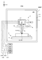
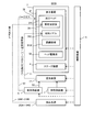
- FIG. 2 is a system configuration diagram showing a system configuration of the processing system of the first embodiment.
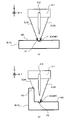
- FIG. 3 is a cross-sectional view showing the structure of the processing head (that is, the irradiation optical system and the material nozzle).
- FIG. 4 is a cross-sectional view showing the structure of the processing head (that is, the irradiation optical system and the material nozzle).
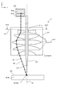
- FIG. 5 is a cross-sectional view showing an optical path of processing light in a virtual optical plane in the condensing optical system that intersects the optical axis of the condensing optical system.
- FIG. 1 is a cross-sectional view showing the structure of the processing system of the first embodiment.
- FIG. 2 is a system configuration diagram showing a system configuration of the processing system of the first embodiment.
- FIG. 3 is a cross-sectional view showing the structure of the processing head (that is, the irradi
- FIG. 6 is a cross-sectional view showing another example of the optical path of the processing light applied to the work through the condensing optical system.
- FIG. 7 is a cross-sectional view showing another example of a region through which the processing lights EL # 1 to EL # 4 pass in the optical surface OP.
- FIG. 8A is a plan view showing the processing light applied to the work
- FIG. 8B is a cross-sectional view showing the processing light applied to the work.
- FIG. 9A is a plan view showing the processing light applied to the work
- FIG. 9B is a cross-sectional view showing the processing light applied to the work.
- FIGS. 10 (a) to 10 (e) is a cross-sectional view showing a state in which a certain region on the work is irradiated with processing light and a modeling material is supplied.
- FIGS. 11 (a) to 11 (c) is a cross-sectional view showing a process of forming a three-dimensional structure.
- FIG. 12 is a plan view showing a target irradiation region (that is, an irradiation position of processing light) that moves toward the + Y side along the Y-axis direction on the modeling surface.
- a target irradiation region that is, an irradiation position of processing light
- FIGS. 15 (a) and 15 (b) are a cut-out view showing how the processing light EL is emitted toward the target irradiation region set on the modeling surface.
- FIG. 16 is a cross-sectional view showing an optical path of processing light in a virtual optical plane in the condensing optical system that intersects the optical axis of the condensing optical system.
- FIG. 17 is a plan view showing an example of a beam spot having a desired shape formed by a plurality of processing lights on the modeling surface).
- FIG. 18 is a cross-sectional view showing the structure of the processing system of the second embodiment.
- FIG. 19 is a system configuration diagram showing a system configuration of the processing system of the second embodiment.
- FIG. 20 is a cross-sectional view showing the optical paths of the measurement light and the object light in the irradiation optical system of the second embodiment (particularly in the condensing optical system).
- FIG. 21 is a cross-sectional view taken along the line XX-XX'of FIG.
- FIG. 22 is a system configuration diagram showing a system configuration of the processing system of the third embodiment.
- FIG. 23 is a cross-sectional view showing the structure of the irradiation optical system of the third embodiment.
- FIGS. 24 (a) to 24 (c) is a cross-sectional view showing an example of an optical path of measurement light applied to a modeling surface.
- FIG. 25 is a system configuration diagram showing a system configuration of the processing system of the fourth embodiment.
- FIG. 26 is a cross-sectional view showing the optical paths of the measurement light and the return light in the irradiation optical system of the fourth embodiment (particularly in the condensing optical system).
- FIG. 27 is a cross-sectional view taken along the line XXVI-XXVI'of FIG. 26.
- FIG. 28 is a system configuration diagram showing a system configuration of the processing system of the fifth embodiment.
- FIG. 29 is a plan view schematically showing the operation of the recovery device and the gas supply device of the fifth embodiment.
- FIG. 30 is a system configuration diagram showing a system configuration of the processing system of the sixth embodiment.
- FIG. 31 is a cross-sectional view showing the structure of the surrounding member of the sixth embodiment.
- FIG. 32 is a system configuration diagram showing a system configuration of the processing system of the seventh embodiment.
- FIG. 33 is a cross-sectional view showing the structure of the processing system of the seventh embodiment.
- each of the X-axis direction and the Y-axis direction is a horizontal direction (that is, a predetermined direction in the horizontal plane), and the Z-axis direction is a vertical direction (that is, a direction orthogonal to the horizontal plane). Yes, it is assumed that it is substantially in the vertical direction or the gravity direction).
- the rotation directions (in other words, the inclination direction) around the X-axis, the Y-axis, and the Z-axis are referred to as the ⁇ X direction, the ⁇ Y direction, and the ⁇ Z direction, respectively.
- the Z-axis direction may be the direction of gravity.
- the XY plane may be horizontal.
- the processing system SYS of the first embodiment First, the machining system SYS of the first embodiment (hereinafter, the machining system SYS of the first embodiment will be referred to as "machining system SYSA") will be described.
- the processing system SYSa of the first embodiment is a processing system capable of forming a three-dimensional structure ST by performing additional processing.
- the processing system SYSa can form a three-dimensional structure ST by performing additional processing based on, for example, a laser overlay welding method (LMD: Laser Metal Deposition).
- the laser overlay welding method (LMD) includes direct metal deposition, direct energy deposition, laser cladding, laser engineered net shaping, direct light fabrication, and laser consolidation.
- the processing system SYSa may form the three-dimensional structure ST by performing additional processing based on other additional processing methods.
- FIG. 1 is a cross-sectional view schematically showing the structure of the processing system SYSA of the first embodiment.
- FIG. 2 is a system configuration diagram showing a system configuration of the processing system SYSA of the first embodiment.
- the processing system SYSa is a three-dimensional structure (that is, a three-dimensional object having a size in any of the three-dimensional directions, and is a three-dimensional object, in other words, in the X-axis direction, the Y-axis direction, and the Z-axis direction.
- An object with a size) ST can be formed.
- the processing system SYSa can form the three-dimensional structure ST on the work W which is the basis (that is, the base material) for forming the three-dimensional structure ST.
- the processing system SYSa can form a three-dimensional structure ST by performing additional processing on the work W. When the work W is the stage 41 described later, the processing system SYSa can form the three-dimensional structure ST on the stage 41.
- the processing system SYSa can form a three-dimensional structure ST on the mounting object.
- the processing system SYSA may form a three-dimensional structure ST integrated with the mounted object.
- the operation of forming the three-dimensional structure ST integrated with the mounting object is equivalent to the operation of adding a new structure to the mounting object.
- the existing structure may be, for example, a repair-required product having a defective portion.
- the processing system SYSa may form a three-dimensional structure ST on the repair-required product so as to fill the defective portion of the repair-required product.
- the processing system SYSA may form a three-dimensional structure ST separable from the mounted object.
- the mounted object mounted on the stage 41 may be another three-dimensional structure ST (that is, an existing structure) formed by the processing system SYS.
- the work W is a mounting object mounted on the stage 41.
- the work W is a work W in which the three-dimensional structure ST is not formed and a work W in which at least a part of the three-dimensional structure ST is formed (that is, the work W).
- Both of the work W) including at least a part of the formed three-dimensional structure ST.
- the processing system SYSa can form a modeled object by the laser overlay welding method. That is, it can be said that the processing system SYSa is a 3D printer that forms an object by using the laminated modeling technique.
- the laminated molding technique may also be referred to as rapid prototyping, rapid manufacturing, or adaptive manufacturing.
- the processing system SYSa processes the modeling material M with the processing optical EL to form a modeled object.
- the modeling material M is a material that can be melted by irradiation with a processing light EL having a predetermined intensity or higher.
- a modeling material M for example, at least one of a metallic material and a resin material can be used.
- the modeling material M a material different from the metallic material and the resin material may be used.
- the modeling material M is a powdery or granular material. That is, the modeling material M is a powder or granular material.
- the modeling material M does not have to be a powder or granular material.
- at least one of a wire-shaped modeling material and a gaseous modeling material may be used.
- the processing system SYSa has a material supply source 1, a plurality of processing light sources 2, a processing device 3, a stage device 4, and a gas, as shown in FIGS. 1 and 2.
- a supply source 5 and a control device 6 are provided.
- the processing device 3 and the stage device 4 may be housed in the chamber space 73IN inside the housing 7.
- the material supply source 1 supplies the modeling material M to the processing device 3.
- the material supply source 1 is formed in a desired amount according to the required amount so that the amount of the modeling material M required per unit time for forming the three-dimensional structure ST is supplied to the processing apparatus 3. Supply material M.
- Each of the plurality of processed light sources 2 emits, for example, at least one of infrared light, visible light, and ultraviolet light as processed light EL.
- the processed light EL may include pulsed light (that is, a pulse beam).
- the processing light EL may be laser light.
- each of the plurality of processing light sources 2 may include a laser light source (for example, a semiconductor laser such as a laser diode (LD)).
- the laser light source may include at least one such as a fiber laser, a CO 2 laser, a YAG laser and an excimer laser.
- the processing light EL does not have to be laser light.
- the processing light source 2 that emits the processing light EL that is not the laser light may include an arbitrary light source (for example, at least one such as an LED (Light Emitting Side) and a discharge lamp).
- the processing system SYSA emits four processing light sources 2 (specifically, processing light source 2 # 1 that emits processing light EL # 1 and processing light source 2 # 2 that emits processing light EL # 2.
- processing light source 2 # 1 that emits processing light EL # 1
- processing light source 2 # 2 that emits processing light EL # 2.
- An example including a processing light source 2 # 3 for emitting the processing light EL # 3 and a processing light source 2 # 4 will be described.
- the number of the processing light sources 2 may be 3 or less, or 5 or more.
- the processing apparatus 3 processes the modeling material M supplied from the material supply source 1 by using the processing lights EL # 1 to EL # 4 propagating from the processing light sources 2 # 1 to 2 # 4, respectively.
- a three-dimensional structure ST is formed.
- the processing apparatus 3 includes a processing head 31 and a head drive system 32.
- the processing device 3 does not have to include the head drive system 32.
- the processing head 31 includes an irradiation optical system 311 and a material nozzle (that is, a material supply device for supplying the modeling material M) 312.
- the processing head 31 and the head drive system 32 are housed in the chamber space 73IN.
- at least a part of the processing head 31 and / or the head drive system 32 may be arranged in the external space 74OUT, which is the space outside the housing 7.
- the external space 74OUT may be a space accessible to the operator of the processing system SYS.
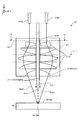
- FIGS. 3 and 4 are cross-sectional views showing the structure of the processing head 31 (that is, the irradiation optical system 311 and the material nozzle 312).
- the irradiation optical system 311 is an optical system in which the processing lights EL # 1 to EL # 4 propagating from the processing light sources 2 # 1 to 2 # 4, respectively, are incident.
- the irradiation optical system 311 is an optical system for emitting EL # 4 from the processed light EL # 1 incident on the irradiation optical system 311.
- the irradiation optical system 311 is optically connected to the processing light sources 2 # 1 to 2 # 4 via a plurality of optical transmission members 21 including at least one such as an optical fiber and a light pipe. ..
- the irradiation optical system 311 is optically connected to the processing light source 2 # 1 via the optical transmission member 21 # 1 and optically via the processing light source 2 # 2 and the optical transmission member 21 # 2. Is optically connected to the processing light source 2 # 3 via the optical transmission member 21 # 3, and is optically connected to the processing light source 2 # 4 via the optical transmission member 21 # 4.
- the irradiation optical system 311 emits EL # 4 from the processed light EL # 1 propagating from the processed light sources 2 # 1 to 2 # 4 via the optical transmission members 21 # 1 to 21 # 4.
- the irradiation optical system 311 emits EL # 4 from the processing light EL # 1 toward the lower side (that is, the ⁇ Z side) from the irradiation optical system 311.
- a stage 41 is arranged below the irradiation optical system 311. When the work W is placed on the stage 41, the irradiation optical system 311 emits EL # 4 from the processing light EL # 1 toward the work W.
- the irradiation optical system 311 may condense the processed light EL # 1 to EL # 4 emitted toward the work W on the work W.
- the irradiation optical system 311 may include a condensing optical system 3111.
- the condensing optical system 3111 is an optical system including a plurality of optical members 3112 (for example, a lens), but may be an optical system including a single optical member 3112.
- the processed light EL # 1 to EL # 4 are used in the optical path of the processed light EL # 1 to EL # 4 among the plurality of optical members 3112 (particularly, the plurality of optical members 3112 having power) included in the condensing optical system 3111.
- the terminal optical member 3114 may be referred to as a final optical member.
- the processed lights EL # 1 to EL # 4 emitted from the condensing optical system 3111 are virtual optical surfaces that intersect the optical axis AX of the condensing optical system 3111 (that is, the optical axis of the irradiation optical system 311).
- the light is focused on the light collecting surface FP. Therefore, the condensing optical system 3111 condenses the processed light EL # 1 to EL # 4 incident on the pupil surface (incident pupil surface) of the condensing optical system 3111 on the condensing surface FP of the condensing optical system 3111. It may also be regarded as an optical system for doing so.
- the processed light EL # 1 to EL # 4 are superimposed on the condensing surface FP. It may mean the state of "light”. That is, in the state of "the processed light EL # 1 to EL # 4 is focused on the condensing surface FP" in the first embodiment, "the processed light EL # 1 to EL # 4 are at the same position on the condensing surface FP". It may mean a state of being "irradiated with light”.
- Such a condensing surface FP is typically set at the rear focal position of the condensing optical system 3111. Note that FIGS.
- the condensing surface FP matches the surface WS of the work W.
- the condensing surface FP is a surface intersecting the Z axis (for example, a surface along the XY plane).
- the entrance pupil surface of the condensing optical system 3111 is located on the outside (incident side) of the condensing optical system 3111, but the entrance pupil surface of the condensing optical system 3111 is the condensing optical system 3111. It may be located inside the.
- the optical paths of the processed light EL # 1 to EL # 4 may be optically separated. That is, in the condensing optical system 3111, the optical paths of the processed lights EL # 1 to EL # 4 may be different from each other. In the condensing optical system 3111, the optical paths of the processed lights EL # 1 to EL # 4 do not have to overlap each other.
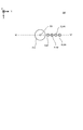
- a virtual optical surface OP in the condensing optical system 3111 intersecting the optical axis AX of the condensing optical system 3111. Is a surface along the XY plane, for example, as shown in FIG. 5, which is a cross-sectional view showing the optical paths of the processed light EL # 1 to EL # 4 in the incident pupil surface of the condensing optical system 3111.
- the processed lights EL # 1 to EL # 4 may each pass through different regions separated from the optical axis AX in different directions.
- the distance between the optical path of # 3 and the distance between the optical axis AX and the optical path of the processed optical EL # 4 may be the same as each other.
- the distances between the optical axis AX and at least two optical paths of the processed light EL # 1 to EL # 4 may be different from each other. In the examples shown in FIGS.
- the distances between the optical axis AX and the optical paths of the processed light EL # 1 to EL # 4 are the same in the optical surface OP.
- the processed light EL # 1 to EL # 4 have a region symmetrical with respect to the optical axis AX in the optical surface OP (a region rotationally symmetric n times with respect to the optical axis AX in the optical surface OP (however, n is 2 or more). Integer)) may be passed.
- the processed optics EL # 1 to EL # 4 have a rotation angle of 270 in the clockwise direction about the origin in the coordinate plane along the XY plane with the optical axis AX as the origin.
- the condensing optical system 3111 When the processing light EL # 1 to EL # 4 pass through different regions separated from each other in different directions from the optical axis AX in the optical surface OP, the condensing optical system 3111 is subjected to processing light EL # 1 to EL.
- the work W may be irradiated with # 4 from different directions. Specifically, as shown in FIGS. 3 to 5, the condensing optical system 3111 transfers the processing light EL # 1 to EL # 4 to the work W from different positions in the rotation direction about the optical axis AX. You may irradiate.
- FIG. 6 is a cross-sectional view showing another example of the optical path of the processed light EL # 1 to EL # 4 irradiated to the work W via the condensing optical system 3111, and the processed light EL # 1 in the optical surface OP. As shown in FIG.
- the processing light EL # 1 to EL # 4 are separated from the optical axis AX by different distances toward the + Y side. It may pass through different areas. That is, the processing light EL # 1 to EL # 4 are the distance between the optical axis AX and the optical path of the processing light EL # 1, the distance between the optical axis AX and the optical path of the processing light EL # 2, and the optical axis AX.
- the condensing optical system 3111 has a condensing optical system 3111.
- the work W is irradiated with the processing lights EL # 1 to EL # 4 so that the angles formed by the traveling directions of the processing lights EL # 1 to EL # 4 and the optical axis AX traveling from the processing light EL # 1 to the work W are different from each other. It is also good. Specifically, as shown in FIG.
- the traveling direction of the processing light EL # 1 and the angle formed by the optical axis AX, and the traveling direction of the processing light EL # 2 and the optical axis AX are different.
- the processing light EL # 1 to EL # so that the angle formed, the angle formed by the traveling direction of the processing light EL # 3 and the optical axis AX, and the angle formed by the traveling direction of the processing light EL # 4 and the optical axis AX are different from each other. 4 may be irradiated to the work W.
- the XY at the ejection ends of the optical transmission members 21 # 1 to 21 # 4 The position along the plane (the plane parallel to the optical plane OP) may be changeable. Further, the positions of the ejection ends of the optical transmission members 21 # 1 to 21 # 4 along the Z direction may also be changed. Further, the processing light emitted from the optical transmission members 21 # 1 to 21 # 4 is the traveling direction of the processing light EL # 1 to EL # 4 (the processing light between the optical transmission members 21 # 1 to 21 # 4 and the condensing optical system). The traveling direction of EL # 1 to EL # 4) may also be changed.
- Each optical member 3112 constituting the condensing optical system 3111 is formed with an opening 3113 that penetrates each optical member 3112 in the direction along the optical axis AX.
- the opening 3113 may be formed at a position where each optical member 3112 and the optical axis AX overlap. That is, the opening 3113 may be formed on the optical axis AX.
- At least a part of the material nozzle 312 is arranged in the plurality of openings 3113 formed in the plurality of optical members 3112, respectively. At least a part of the material nozzle 312 is inserted into the plurality of openings 3113.
- the material nozzle 312 may be inserted into the opening 3113 so that the supply outlet 314 at the tip of the material nozzle 312 is arranged outside the opening 3113. Therefore, the material nozzle 312 is arranged so that at least a part of the material nozzle 312 is surrounded by a plurality of optical members 3112.
- the openings 3113 are formed on the optical axis AX
- at least a part of the material nozzles 312 may be arranged along the optical axis AX in the plurality of openings 3113. In this case, at least a part of the material nozzle 312 may be arranged on the optical axis AX.
- the processed light EL # 1 to EL # 4 pass through a portion of each optical member 3112 in which the opening 3113 is not formed.
- the processed light EL # 1 to EL # 4 pass through a portion of each optical member 3112 that is separated from the optical axis AX.
- the processing light EL # 1 to EL # 4 may travel from the condensing optical system 3111 toward the work W along a direction inclined with respect to the optical axis AX. That is, the condensing optical system 3111 may emit the processing light EL # 1 to EL # 4 along the direction inclined with respect to the optical axis AX.
- the purge gas supplied from the gas supply source 5 to the chamber space 73IN passes through the opening 3113 to the space on the injection surface side of the terminal optical member 3114 (that is, the work). It may be supplied to the space on the W side).
- the purge gas supplied from the gas supply source 5 to the chamber space 73IN may be supplied between a plurality of optical members 3112 constituting the condensing optical system 3111.
- the purge gas supplied between the plurality of optical members 3112 constituting the condensing optical system 3111 passes through the opening 3113 (particularly, the opening 3113 of the terminal optical member 3114) into the space on the injection surface side of the terminal optical member 3114. It may be supplied.
- a supply outlet 314 is formed in the material nozzle 312.
- the material nozzle 312 supplies the molding material M from the supply outlet 314 (eg, ejects, ejects, ejects, or sprays).
- the material nozzle 312 is physically connected to the material supply source 1 which is the supply source of the modeling material M via the supply pipe 11 and the mixing device 12.
- the material nozzle 312 supplies the modeling material M supplied from the material supply source 1 via the supply pipe 11 and the mixing device 12.
- the material nozzle 312 may pump the modeling material M supplied from the material supply source 1 via the supply pipe 11.
- the modeling material M from the material supply source 1 and the transporting gas (that is, the pumping gas, that is, an inert gas such as nitrogen or argon) are mixed by the mixing device 12 and then the supply pipe 11 is connected. It may be pumped to the material nozzle 312 via. As a result, the material nozzle 312 supplies the modeling material M together with the conveying gas.
- the transporting gas for example, purge gas supplied from the gas supply source 5 is used.
- a gas supplied from a gas supply source different from the gas supply source 5 may be used.
- the material nozzle 312 is drawn in a tubular shape in FIGS. 3 to 4, the shape of the material nozzle 312 is not limited to this shape.
- the material nozzle 312 supplies the modeling material M downward (that is, the ⁇ Z side) from the material nozzle 312. At this time, since the material nozzle 312 is arranged in the opening 3113 of the optical member 3112, the material nozzle 312 passes the modeling material M through the opening 3113 of the optical member 3112 (particularly, the opening 3113 of the terminal optical member 3114). It may be considered as supplying.
- the material nozzle 312 supplies the modeling material M through the space inside the optical path of the processing light EL # 1 to EL # 4 emitted through the portion of the optical member 3112 where the opening 3113 is not formed. It may be considered that there is.
- a stage 41 is arranged below the material nozzle 312. When the work W is mounted on the stage 41, the material nozzle 312 supplies the modeling material M toward the work W or the vicinity of the work W.
- the material nozzle 312 supplies the modeling material M to the work W from the direction intersecting the surface WS of the work W.
- the material nozzle 312 supplies the modeling material M to the work W from the Z-axis direction intersecting the surface WS of the work W. That is, the material nozzle 312 supplies the modeling material M so that the supply path of the modeling material M from the material nozzle 312 to the work W is a path along the Z-axis direction.
- the condensing optical system 3111 performs the processing light EL.
- the supply direction of the modeling material M by the material nozzle 312 (which may be referred to as the material supply direction) may be different from the irradiation direction of the processing light EL # 1 to EL # 4 by the condensing optical system 3111.
- the material nozzle 312 irradiates the target irradiation region EA in which the irradiation optical system 311 irradiates the processing light EL # 1 to EL # 4 (that is, the irradiation optical system 311 irradiates the processing light EL # 1 to EL # 4). It is aligned with the irradiation optical system 311 so as to supply the modeling material M toward the position (position). That is, the target supply region MA and the target irradiation region EA, which are set on or near the work W as the region where the material nozzle 312 supplies the modeling material M, coincide with (or at least partially overlap).
- the material nozzle 312 and the irradiation optical system 311 are aligned. Further, as will be described later, a molten pool MP is formed on the work W by the processing lights EL # 1 to EL # 4 emitted from the irradiation optical system 311.
- the material nozzle 312 may be aligned with the irradiation optical system 311 so as to supply the modeling material M to the molten pool MP. However, the material nozzle 312 does not have to supply the modeling material M to the molten pool MP.
- the modeling material M from the material nozzle 312 is melted by the processing light EL # 1 to EL # 4 from the irradiation optical system 311 before reaching the work W, and the molten modeling is performed.
- the material M may be attached to the work W.
- the opening 3113 in which the material nozzle 312 is arranged is used as a supply path for the purge gas supplied to the space on the injection surface side of the terminal optical member 3114.
- the purge gas supplied through the opening 3113 forms, for example, a gas flow toward the supply outlet 314 at the tip of the material nozzle 312.
- a gas flow increases the possibility that the modeling material M from the supply outlet 314 will be supplied along the downward supply path from the material nozzle 312. That is, the possibility that the modeling material M from the supply outlet 314 is scattered in all directions from the material nozzle 312 is reduced.
- the material nozzle 312 can appropriately supply the modeling material M. That is, the processing system SYSa can improve the directivity of the modeling material M in the supply direction.
- the head drive system 32 moves the processing head 31.
- the head drive system 32 moves the machining head 31 along at least one of the X-axis, the Y-axis, the Z-axis, the ⁇ X direction, the ⁇ Y direction, and the ⁇ Z direction, for example.
- the relative positions of the machining head 31 and the work W mounted on the stage 41 and the stage 41 change. That is, the relative positions of the irradiation optical system 311 and the material nozzle 312 and the stage 41 and the work W are changed.
- the head drive system 32 may function as a moving device for moving the target irradiation region EA and the target supply region MA (further, the molten pool MP) with respect to the work W.
- the head drive system 32 moves the processing head 31 along the Z-axis direction (that is, the direction along the optical axis AX of the condensing optical system 3111), the processing light EL # 1 to EL # 4 are condensed.
- the distance DS between the condensing surface FP of the condensing optical system 3111 and the surface WS of the work W changes. Therefore, the head drive system 32 may function as a distance changing device for changing the distance DS between the condensing surface FP of the condensing optical system 3111 and the surface WS of the work W in the Z-axis direction.
- the head drive system 32 collects light in the Z-axis direction so that the light-collecting surface FP of the light-collecting optical system 3111 coincides with the surface WS of the work W (or the modeling surface MS described later, the same applies hereinafter) in the Z-axis direction.
- the distance DS between the surface FP and the surface WS of the work W may be changed. That is, the head drive system 32 may change the distance DS so that the distance DS becomes zero.
- FIG. 8A is a plan view showing the processing lights EL # 1 to EL # 4 irradiated on the work W, and a cross-sectional view showing the processing lights EL # 1 to EL # 4 irradiated on the work W. As shown in FIG.
- the processing lights EL # 1 to EL # 4 are focused on the surface WS of the work W. That is, the processing lights EL # 1 to EL # 4 are superimposed on the surface WS of the work W. In this case, a single beam spot irradiated with the processing light EL # 1 to EL # 4 is formed on the surface WS of the work W.
- the distance between the condensing surface FP and the surface WS of the work W in the Z-axis direction is such that the condensing surface WS of the condensing optical system 3111 deviates from the surface WS of the work W in the Z-axis direction.
- FIG. 9A is a plan view showing the processing lights EL # 1 to EL # 4 irradiated on the work W, and a cross-sectional view showing the processing lights EL # 1 to EL # 4 irradiated on the work W. As shown in FIG.
- the processing lights EL # 1 to EL # 4 are not focused on the surface WS of the work W. That is, the processing light EL # 1 to EL # 4 are not superimposed on the surface WS of the work W.
- four beam spots irradiated with the processing lights EL # 1 to EL # 4 are formed on the surface WS of the work W.
- the positional relationship of the four beam spots and the size of the four beam spots change depending on the distance between the focusing surface of the focusing optical system 3111 and the surface of the work W in the Z-axis direction.
- the four beam spots do not overlap each other, but at least two of the four beam spots may partially overlap. Further, in the examples shown in FIGS.
- the processing lights EL # 1 to EL # 4 do not intersect with each other, but after the processing lights EL # 1 to EL # 4 intersect with each other, they intersect with each other.
- the processing light EL # 1 to EL # 4 may be applied to the surface WS of the work W in a separated state.
- the head drive system 32 may function as a device for changing the distribution (for example, intensity distribution) of the processing light EL # 1 to EL # 4 on the surface WS of the work W.
- the stage device 4 includes a stage 41 and a stage drive system 42. However, the stage device 4 does not have to include the stage drive system 42.
- the stage 41 may be referred to as a table.
- Stage 41 can support work W.
- the state in which the work W supports the work W may mean a state in which the work W is directly or indirectly supported by the stage 41.
- the stage 41 may be able to hold the work W placed on the stage 41. That is, the stage 41 may support the work W by holding the work W.
- the stage 41 may be provided with a mechanical chuck, a vacuum suction chuck, or the like in order to hold the work W.
- the stage 41 does not have to be able to hold the work W.
- the work W may be mounted on the stage 41 without being clamped. Further, the stage 41 may be able to release the held work W when the work W is held.
- the irradiation optical system 311 described above irradiates the work W with the processing lights EL # 1 to EL # 4 during at least a part of the period in which the stage 41 supports the work W. Further, the material nozzle 312 described above supplies the modeling material M for at least a part of the period during which the stage 41 supports the work W.
- the stage drive system 42 moves the stage 41. Therefore, the stage drive system 42 may be referred to as a mobile device.
- the stage drive system 42 moves the stage 41 along at least one of the X-axis, the Y-axis, the Z-axis, the ⁇ X direction, the ⁇ Y direction, and the ⁇ Z direction, for example.
- the stage drive system 42 moves the stage 41, the relative positions of the processing head 31 and the work W mounted on the stage 41 and the stage 41 change. Therefore, the stage drive system 42 functions as a moving device for moving the target irradiation region EA and the target supply region MA (furthermore, the molten pool MP) relative to the work W, similarly to the head drive system 32. You may.
- the stage drive system 42 moves the stage 41 along the Z-axis direction (that is, the direction along the optical axis AX of the focusing optical system 3111), the processing light EL # 1 to EL # 4 are focused.
- the distance DS between the condensing surface FP of the condensing optical system 3111 and the surface WS of the work W changes. Therefore, the stage drive system 42, like the head drive system 32, changes the distance DS for changing the distance DS between the condensing surface FP of the condensing optical system 3111 and the surface WS of the work W in the Z-axis direction. It may function as a device. Similar to the head drive system 32, the stage drive system 42 may function as a device for changing the distribution (for example, intensity distribution) of the processing light EL # 1 to EL # 4 on the surface WS of the work W.
- the gas supply source 5 is a supply source of purge gas for purging the chamber space 73IN.
- the purge gas contains an inert gas.
- the inert gas nitrogen gas or argon gas can be mentioned.
- the gas supply source 5 is connected to the chamber space 73IN via a supply port 72 formed in the partition member 71 of the housing 7 and a supply pipe 51 connecting the gas supply source 5 and the supply port 72.
- the gas supply source 5 supplies purge gas to the chamber space 73IN via the supply pipe 51 and the supply port 72.
- the chamber space 73IN becomes a space purged by the purge gas.
- the gas supply source 5 may be a cylinder in which an inert gas such as nitrogen gas or argon gas is stored.
- the inert gas is nitrogen gas
- the gas supply source 5 may be a nitrogen gas generator that generates nitrogen gas from the atmosphere as a raw material.
- the gas supply source 5 may supply the purge gas to the mixing device 12 to which the modeling material M from the material supply source 1 is supplied. good.
- the gas supply source 5 may be connected to the mixing device 12 via a supply pipe 52 that connects the gas supply source 5 and the mixing device 12.
- the gas supply source 5 supplies the purge gas to the mixing device 12 via the supply pipe 52.
- the modeling material M from the material supply source 1 is supplied toward the material nozzle 312 through the supply pipe 11 by the purge gas supplied from the gas supply source 5 via the supply pipe 52 (specifically,). , Pumped).
- the gas supply source 5 may be connected to the material nozzle 312 via the supply pipe 52, the mixing device 12, and the supply pipe 11. In that case, the material nozzle 312 will supply the modeling material M together with the purge gas for pumping the modeling material M from the supply outlet 314.
- the control device 6 controls the operation of the processing system SYS.
- the control device 6 may include, for example, an arithmetic unit and a storage device.
- the arithmetic unit may include, for example, at least one of a CPU (Central Processing Unit), a GPU (Graphics Processing Unit), and an FPGA (Field Programmable Gate Array).
- the storage device may include, for example, a memory.
- the control device 6 functions as a device that controls the operation of the processing system SYS by executing a computer program by the arithmetic unit.
- This computer program is a computer program for causing the arithmetic unit to perform (that is, execute) the operation described later to be performed by the control device 6.
- this computer program is a computer program for causing the control device 6 to function so that the processing system SYSa performs an operation described later.
- the computer program executed by the arithmetic unit may be recorded in a storage device (that is, a recording medium) included in the control device 6, or any storage built in the control device 6 or externally attached to the control device 6. It may be recorded on a medium (for example, a hard disk or a semiconductor memory). Alternatively, the arithmetic unit may download the computer program to be executed from an external device of the control device 6 via the network interface.
- the control device 6 may control the emission mode of the processed light EL # 1 to EL # 4 by the irradiation optical system 311.
- the injection mode may include, for example, at least one of the intensity of the processing light EL # 1 to EL # 4 and the injection timing of the processing light EL # 1 to EL # 4.
- the emission modes are, for example, the emission time of the pulsed light, the emission period of the pulsed light, and the length of the emission time of the pulsed light and the pulsed light. It may include at least one of the ratios (so-called duty ratios) to the light emission period of.
- control device 6 may control the movement mode of the processing head 31 by the head drive system 32.
- the control device 6 may control the movement mode of the stage 41 by the stage drive system 42.
- the movement mode may include, for example, at least one of a movement amount, a movement speed, a movement direction, and a movement timing (movement timing).
- the control device 6 may control the supply mode of the modeling material M by the material nozzle 312.
- the supply mode may include, for example, at least one of a supply amount (particularly, a supply amount per unit time) and a supply timing (supply timing).
- the control device 6 does not have to be provided inside the processing system SYS.
- the control device 6 may be provided as a server or the like outside the processing system SYS.
- the control device 6 and the processing system SYSA may be connected by a wired and / or wireless network (or a data bus and / or a communication line).
- a wired network for example, a network using a serial bus type interface represented by at least one of IEEE1394, RS-232x, RS-422, RS-423, RS-485 and USB may be used.
- a network using a parallel bus interface may be used.
- a network using an Ethernet (registered trademark) compliant interface represented by at least one of 10BASE-T, 100BASE-TX and 1000BASE-T may be used.
- a network using radio waves may be used.
- An example of a network using radio waves is a network conforming to IEEE802.1x (for example, at least one of wireless LAN and Bluetooth®).
- a network using infrared rays may be used.
- a network using optical communication may be used.
- the control device 6 and the processing system SYSA may be configured so that various types of information can be transmitted and received via the network.
- control device 6 may be able to transmit information such as commands and control parameters to the processing system SYSA via the network.
- the processing system SYSa may include a receiving device that receives information such as commands and control parameters from the control device 6 via the network. Even if the processing system SYSa is provided with a transmission device (that is, an output device that outputs information to the control device 6) that transmits information such as commands and control parameters to the control device 6 via the network. good.
- a transmission device that is, an output device that outputs information to the control device 6
- the second control device that performs the other part of the processing performed by the control device 6 is provided.
- the control device may be provided outside the processing system SYS.
- the recording medium for recording the computer program executed by the control device 6 includes a CD-ROM, a CD-R, a CD-RW, a flexible disk, an MO, a DVD-ROM, a DVD-RAM, a DVD-R, a DVD + R, and a DVD.
- -Used by at least one of optical disks such as RW, DVD + RW and Blu-ray (registered trademark), magnetic media such as magnetic tape, magneto-optical disks, semiconductor memories such as USB memory, and other media capable of storing programs. May be done.
- the recording medium may include a device capable of recording a computer program (for example, a general-purpose device or a dedicated device in which the computer program is implemented in a state in which it can be executed in at least one form such as software and firmware).
- each process or function included in the computer program may be realized by a logical processing block realized in the control device 6 by the control device 6 (that is, the computer) executing the computer program. It may be realized by hardware such as a predetermined gate array (FPGA, ASIC) included in the control device 6, or a logical processing block and a partial hardware module that realizes a part of the hardware are mixed. It may be realized in the form of.
- the housing 7 is a storage device that accommodates at least a part of each of the processing device 3 and the stage device 4 in the chamber space 73IN, which is the internal space of the housing 7.
- the housing 7 includes a partition member 71 that defines the chamber space 73IN.
- the partition member 71 is a member that separates the chamber space 73IN from the external space 74OUT of the housing 7.
- the partition member 71 faces the chamber space 73IN via its inner wall 711 and faces the outer space 74OUT via its outer wall 712. In this case, the space surrounded by the partition member 71 (more specifically, the space surrounded by the inner wall 711 of the partition member 71) becomes the chamber space 73IN.
- the partition member 71 may be provided with a door that can be opened and closed.
- This door may be opened when the work W is placed on the stage 41.
- the door may be opened when the work W and / or the modeled object is taken out from the stage 41.
- the door may be closed during processing (ie, during additional processing or joining processing).
- An observation window (not shown) for visually recognizing the chamber space 73IN from the external space 74OUT of the housing 7 may be provided on the partition wall member 71.
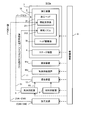
- the machining system SYSa performs an additional machining operation for forming the three-dimensional structure ST on the work W. Further, the processing system SYSa performs an optical characteristic control operation for controlling at least one characteristic of the processing light EL # 1 to the processing light EL # 4 during at least a part of the period during which the additional processing operation is performed. Therefore, in the following, the additional processing operation and the optical characteristic control operation will be described in order.
- (1-2-1) Addition processing operation First , the addition processing operation will be described. As described above, the processing system SYSa forms the three-dimensional structure ST by the laser overlay welding method.
- the processing system SYSA may form the three-dimensional structure ST by performing an existing additional processing operation (in this case, a modeling operation) based on the laser overlay welding method.
- an existing additional processing operation in this case, a modeling operation
- the laser overlay welding method may form the three-dimensional structure ST by performing an existing additional processing operation (in this case, a modeling operation) based on the laser overlay welding method.
- the processing system SYSa forms the three-dimensional structure ST on the work W based on the three-dimensional model data (for example, CAD (Computer Aided Design) data) of the three-dimensional structure ST to be formed.
- the three-dimensional model data for example, CAD (Computer Aided Design) data
- the processing system SYSa sequentially forms, for example, a plurality of layered partial structures (hereinafter, referred to as “structural layers”) SLs arranged along the Z-axis direction.
- the processing system SYSa sequentially forms a plurality of structural layers SL obtained by cutting the three-dimensional structure ST into round slices along the Z-axis direction.
- a three-dimensional structure ST which is a laminated structure in which a plurality of structural layers SL are laminated, is formed.
- the flow of the operation of forming the three-dimensional structure ST by sequentially forming the plurality of structural layers SL one by one will be described.
- the processing system SYSa processes the target irradiation region EA under the control of the control device 6 so that the target irradiation region EA is set in the desired region on the modeling surface MS corresponding to the surface WS of the work W or the surface of the formed structural layer SL. At least one of the head 31 and the stage 41 is moved. After that, the processing system SYSa irradiates the target irradiation region EA with the processing light EL # 1 to EL # 4 from the irradiation optical system 311.
- the condensing surface FP on which the processing light EL # 1 to EL # 4 are focused in the Z-axis direction may coincide with the modeling surface MS (FIGS. 8A and 8B). reference).
- the condensing surface FP on which the processing light EL # 1 to EL # 4 are focused in the Z-axis direction may be deviated from the modeling surface MS (see FIGS. 9A and 9B). ..
- a molten pool a molten pool ( That is, a pool of metal melted by the processing light EL # 1 to EL # 4) MP is formed.
- the processing system SYSa supplies the modeling material M from the material nozzle 312 under the control of the control device 6.
- the target supply region MA to which the modeling material M is supplied coincides with the target irradiation region EA as described above, the target supply region MA includes at least a part of the region where the molten pool MP is formed. .. Therefore, as shown in FIG. 10B, the processing system SYSa supplies the modeling material M to the molten pool MP from the material nozzle 312. As a result, the modeling material M supplied to the molten pool MP is melted.
- the molding material M melted in the molten pool MP is cooled and solidified (that is, solidified). ..
- the solidified modeling material M is deposited on the modeling surface MS. That is, a modeled object is formed by the deposit of the solidified modeling material M.
- the processing system SYSa is capable of forming a molten pool MP by irradiating the processing light EL # 1 to EL # 4, supplying the modeling material M to the molten pool MP, melting the supplied modeling material M, and melting the molten modeling material.
- a series of modeling processes including solidification of M is repeated while moving the processing head 31 relative to the modeling surface MS along the XY plane.
- the processing system SYS irradiates the area on the modeling surface MS on which the modeled object is to be formed with the processing light EL # 1 to EL # 4, while processing the area on the modeling surface MS where the modeled object is not desired to be formed. Do not irradiate EL # 1 to EL # 4.
- the processing system SYSa moves the target irradiation region EA along the predetermined movement locus on the modeling surface MS, and the processing light EL # 1 to EL at the timing corresponding to the distribution mode of the region where the modeled object is to be formed. Irradiate the modeling surface MS with # 4.
- the molten pool MP also moves on the modeling surface MS along the movement locus according to the movement locus of the target irradiation region EA.
- the molten pool MP is sequentially formed on the modeling surface MS in the portion of the region along the movement locus of the target irradiation region EA that is irradiated with the processing light EL # 1 to EL # 4.
- a structural layer SL corresponding to an aggregate of the modeled objects made of the modeling material M that has been melted and then solidified is formed on the modeling surface MS. That is, the structural layer SL corresponding to the aggregate of the shaped objects formed on the modeling surface MS in the pattern corresponding to the moving locus of the molten pool MP (that is, the shape corresponding to the moving locus of the molten pool MP in a plan view).
- the structural layer SL) to have is formed.
- the supply may be stopped. Further, when the target irradiation region EA is set in the region where the modeled object is not to be formed, the processing system SYSa supplies the modeling material M to the target irradiation region EA, and at the same time, the processing light having an intensity that does not allow the molten pool MP to be formed. EL # 1 to EL # 4 may be applied to the target irradiation region EA.
- the processing system SYSa repeatedly performs the operation for forming such a structural layer SL under the control of the control device 6 based on the three-dimensional model data. Specifically, first, the control device 6 creates slice data by slicing the three-dimensional model data at a stacking pitch. Note that data obtained by partially modifying this slice data may be used according to the characteristics of the processing system SYS.
- the processing system SYSa performs an operation for forming the first structural layer SL # 1 on the modeling surface MS corresponding to the surface WS of the work W with three-dimensional model data corresponding to the structural layer SL # 1 (that is, that is). This is performed based on the slice data corresponding to the structural layer SL # 1.
- the structural layer SL # 1 is formed on the modeling surface MS as shown in FIG. 11A.
- the processing system SYS sets the surface (that is, the upper surface) of the structural layer SL # 1 on the new modeling surface MS, and then forms the second structural layer SL # 2 on the new modeling surface MS. do.
- the control device 6 first controls the head drive system 32 so that the machining head 31 moves along the Z axis. Specifically, the control device 6 controls the head drive system 32 so that the target irradiation region EA and the target supply region MA are set on the surface of the structural layer SL # 1 (that is, the new modeling surface MS). The machining head 31 is moved toward the + Z side.
- the processing system SYSa operates on the structural layer SL # 1 based on the slice data corresponding to the structural layer SL # 2 in the same operation as the operation of forming the structural layer SL # 1 under the control of the control device 6.
- the structural layer SL # 2 is formed on the surface.
- the structural layer SL # 2 is formed.
- the same operation is repeated until all the structural layers SL constituting the three-dimensional structure ST to be formed on the work W are formed.
- the three-dimensional structure ST is formed by the laminated structure in which a plurality of structural layers SL are laminated.
- the optical characteristic control operation is mainly performed under the control of the control device 6. That is, the control device 6 controls (in other words, changes or changes) at least one characteristic of the processing light EL # 1 to EL # 4 during at least a part of the period during which the additional processing operation is performed by performing the optical characteristic control operation. Adjustment) may be performed.
- the control device 6 may individually control at least one characteristic of the processing light EL # 1 to EL # 4. That is, the control device 6 controls the characteristics of the processing light EL of one of the processing lights EL # 1 to EL # 4 and the characteristics of the other processing light EL of the processing lights EL # 1 to EL # 4. It may or may not be controlled. At this time, the control device may control the respective characteristics of the processing light EL # 1 to EL # 4. That is, the control device controls the characteristics of the processing light EL # 1, controls the characteristics of the processing light EL # 2, controls the characteristics of the processing light EL # 3, and controls the characteristics of the processing light EL # 4. May be good.
- control device may control at least one characteristic of the processing light EL # 1 to the processing light EL # 4, while not controlling at least one other characteristic of the processing light EL # 1 to EL # 4. good. That is, the control device 6 may control at least one characteristic of the processing light EL # 1 to EL # 4, while fixing at least one other characteristic of the processing light EL # 1 to EL # 4. For example, the control device 6 controls the characteristics of the processing light EL # 1 and EL # 2, but does not have to control the characteristics of the processing light EL # 3 and EL # 4 (fixed). May be good).
- the control device 6 has the processing light EL # 1 so that at least one characteristic of the processing light EL # 1 to EL # 4 is different from at least one characteristic of the processing light EL # 1 to EL # 4. At least one characteristic of EL # 4 may be controlled from. In other words, the control device 6 makes the processing light different from at least one characteristic of the processing light EL # 1 to EL # 4 from at least one other characteristic of the processing light EL # 1 to EL # 4. At least one characteristic of EL # 1 to EL # 4 may be set (in other words, determined). In this case, the control device 6 controls at least one characteristic of the processing light EL # 1 to EL # 4 so that at least one characteristic of the processing light EL # 1 to EL # 4 becomes the set characteristic.
- control device 6 sets the characteristics of the processing light EL # 1 so that the characteristics of the processing light EL # 1 are different from the characteristics of the processing light EL # 2 to EL # 4, and sets the characteristics of the processing light EL # 1.
- the characteristic of the processing light EL # 1 may be controlled so that the characteristic of # 1 becomes the set characteristic.
- the characteristics of the processed light EL may include the strength of the processed light EL.
- the control device 6 may control at least one intensity of the processing light EL # 1 to EL # 4.
- the "strength of the processing light EL” referred to here may mean the strength of the processing light EL on the surface intersecting the traveling direction of the processing light EL.
- the "intensity of the processing light EL” means the intensity of the processing light EL on the modeling surface MS (for example, the surface WS of the work W or the surface of the structural layer SL) where the additional processing is actually performed. You may.
- the characteristics of the processed light EL may include the intensity distribution of the processed light EL.
- the control device 6 may control at least one intensity distribution of the processing light EL # 1 to EL # 4.
- the "intensity distribution of the processing light EL" referred to here may mean the intensity of the processing light EL in the plane intersecting the traveling direction of the processing light EL.
- the "intensity distribution of the processing light EL” means the intensity distribution of the processing light EL in the modeling surface MS (for example, the surface WS of the work W or the surface of the structural layer SL) where the additional processing is actually performed. You may be doing it.
- the characteristics of the processed light EL may include the polarization distribution of the processed light EL. That is, the characteristic of the processed light EL is the distribution of the polarized light components contained in the processed light EL (for example, the distribution of the polarized light components in the plane intersecting the traveling direction of the processed light EL (typically, the modeling surface MS)). May include.
- the characteristics of the processed light EL may include the wavelength distribution of the processed light EL. That is, the characteristic of the processed light EL is the distribution of the optical components of each wavelength or each wavelength band included in the processed light EL (for example, within the surface intersecting the traveling direction of the processed light EL (typically, the modeling surface MS). (Distribution of light components in) may be included.
- the control device 6 may control the formation state of the molten pool MP by controlling the characteristics of the processing light EL (for example, at least one of the intensity and the intensity distribution).
- the control device 6 controls the characteristics of the processing light EL (for example, at least one of the intensity and the intensity distribution) so that the formation state of the molten pool MP becomes a desired formation state (that is, an ideal formation state).
- the formation state of the molten pool MP may be controlled.
- the control device 6 may control the formation state of the molten pool MP based on the measurement result of the measuring device capable of measuring the formation state of the molten pool MP.
- the measuring device capable of measuring the formation state of the molten pool MP.
- the control device 6 may control the formation state of the molten pool MP based on the measurement result of the formation state of the molten pool MP by a measuring device different from the measuring device 82b.
- the formation state of the molten pool MP may include the temperature distribution of the molten pool MP.
- the control device 6 adjusts the characteristics of the processed light EL (for example, at least one of the intensity and the intensity distribution) so that the temperature distribution of the molten pool MP becomes a desired temperature distribution (that is, an ideal temperature distribution). You may control it.
- the size of the molten pool MP may change. For example, if the temperature distribution of the molten pool MP changes, the size (that is, width, length) of the molten pool MP in the direction along the modeling surface MS may change. For example, if the temperature distribution of the molten pool MP changes, the size (that is, the depth) of the molten pool MP in the direction intersecting the modeling surface MS may change. Therefore, the formation state of the molten pool MP may include the size of the molten pool MP. In this case, the control device 6 adjusts the characteristics of the processed light EL (for example, at least one of the intensity and the intensity distribution) so that the size of the molten pool MP becomes a desired size (that is, an ideal size). You may control it.
- the characteristics of the processed light EL for example, at least one of the intensity and the intensity distribution
- the control device 6 In order to control at least one characteristic of the processing light EL # 1 to EL # 4, the control device 6 generates at least one of the processing light sources 2 # 1 to 2 # 4 that generate the processing light EL # 1 to EL # 4, respectively. You may control one. Specifically, the control device 6 may control the characteristics of the processing light EL # 1 by controlling the processing light source 2 # 1. The control device 6 may control the characteristics of the processing light EL # 2 by controlling the processing light source 2 # 2. The control device 6 may control the characteristics of the processing light EL # 3 by controlling the processing light source 2 # 3. The control device 6 may control the characteristics of the processing light EL # 4 by controlling the processing light source 2 # 4.
- the control device 6 includes a condensing surface FP on which the condensing optical system 3111 condenses the processed light EL # 1 to EL # 4.
- the distance DS in the Z-axis direction between the surface WS of the work W and the surface WS may be controlled. This is because, as described above, when the distance DS changes, the distribution (for example, intensity distribution) of the processing light EL # 1 to EL # 4 on the surface WS (or the modeling surface MS) of the work W changes. Therefore, the control device 6 controls the distance DS so that the distance DS can be changed so that at least one characteristic of the processed light EL # 1 to EL # 4 becomes a desired characteristic. At least one of the drive system 42 may be controlled.
- control device 6 is an optical member included in the irradiation optical system 311 and at least one of the processing light EL # 1 to EL # 4.
- An optical member whose characteristics can be controlled may be controlled.
- the control device 6 may control at least one characteristic of the processing light EL # 1 to EL # 4 based on the movement information regarding the movement of the target irradiation region EA on the modeling surface MS.
- the target irradiation region EA moves with the movement of the processing head 31 by the head drive system 32 and the movement of the stage 41 by the stage drive system 42. Therefore, the operation of controlling at least one characteristic of the processing light EL # 1 to EL # 4 based on the movement information regarding the movement of the target irradiation region EA is substantially one of the processing head 31 and the stage 41. It may be regarded as equivalent to the operation of controlling at least one characteristic of the processing light EL # 1 to EL # 4 based on the information regarding the movement.
- the movement information regarding the movement of the target irradiation region EA may include information regarding the movement direction of the target irradiation region EA on the modeling surface MS (that is, the movement direction of the irradiation positions of the processing lights EL # 1 to EL # 4). ..
- the control device 6 may control at least one characteristic of the processing light EL # 1 to EL # 4 based on the moving direction of the target irradiation region EA on the modeling surface MS.
- the control device 6 may control at least one characteristic of the machining light EL # 1 to EL # 4 based on the moving direction of at least one of the machining head 31 and the stage 41.
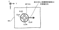
- FIG. 12 is a plan view showing a target irradiation region EA (that is, irradiation positions of the processing lights EL # 1 to EL # 4) moving toward the + Y side along the Y-axis direction on the modeling surface MS. ..
- the irradiation position of the processing light EL # 2 is located relatively forward (that is, the + Y side) in the moving direction of the target irradiation region EA, and the irradiation position of the processing light EL # 1 is set.
- the target irradiation region EA is located relatively rearward (that is, -Y side) in the moving direction.
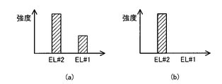
- the control device 6 may control at least one of the characteristics of the processing light EL # 1 and EL # 2 so that the characteristics of the processing light EL # 1 are different from the characteristics of the processing light EL # 2. good.
- FIG. 13A shows an example in which the intensity of the processing light EL # 1 is higher than zero
- FIG. 13B shows an example in which the intensity of the processing light EL # 2 becomes zero.
- the processing system SYSa can appropriately process the work W.
- the control device 6 may control the characteristics (for example, intensity or intensity distribution) of the processing light EL # 1 so that the processing light EL # 1 becomes pulsed light.
- the control device 6 may control the characteristics (intensity) of the processing light EL # 2 so that the processing light EL # 2 becomes continuous light (CW: Continuous Wave).
- the processing light EL # 1 irradiated to a position relatively rearward in the moving direction becomes pulsed light
- the processing light EL # 2 irradiated to a position relatively forward in the moving direction becomes continuous light
- the processing trace of the modeling surface MS by the processing light EL # 2 is smoothed by the processing light EL # 2, which is pulsed light. Therefore, the processing system SYSa can appropriately process the work W.
- the processing system SYSa can form a three-dimensional structure ST having a relatively smooth surface.
- the control device 6 may control at least one of the processing light EL # 1 and the processing light EL # 2 so that the integrated light amount of the processing light EL # 1 and the integrated light amount of the processing light EL # 2 are different from each other. good.
- the control device 6 may control at least one characteristic of the processing light EL # 1 to EL # 4 based on the work information regarding the work W to be processed, in addition to or instead of the movement information described above.
- the work information regarding the work W may include information regarding the shape of the work W.
- the control device 6 may control at least one characteristic of the processing light EL # 1 to EL # 4 based on the shape of the work W.
- the information on the shape of the work W is information on the shape of the work W including a part of the formed three-dimensional structure ST. May include.
- the intensity of the processing light EL applied to the portion of the work W to be processed becomes equal to or higher than the processable strength sufficient to process the work W.
- at least one characteristic (for example, intensity or intensity distribution) of the processing light EL # 1 to EL # 4 may be controlled.
- the intensity of the processing light EL applied to the portion of the work W that should not be processed is equal to or less than the unprocessable strength to the extent that the work W cannot be processed.
- At least one characteristic (for example, intensity or intensity distribution) of the processing light EL # 1 to EL # 4 may be controlled so as to be. For example, FIG.
- the control device 6 has the characteristics of the processing lights EL # 1 and EL # 2 so that the strengths of the processing lights EL # 1 and EL # 2 are equal to or higher than the processing strength. For example, intensity or intensity distribution) may be controlled.
- FIG. 15B shows the target irradiation region EA toward the target irradiation region EA under the condition that the target irradiation region EA is set in the second portion P2 in order to process the second portion P2 of the modeling surface MS.
- the control device 6 may control the characteristics (for example, intensity or intensity distribution) of the processing light EL # 2 so that the intensity of the processing light EL # 2 becomes equal to or higher than the processable intensity. good.
- the processing light EL # 1 does not irradiate the second portion P2 of the work W to be processed.
- the third portion P3 of the work W which should not be processed, exists on the optical path of the processed light EL # 1 from the irradiation optical system 211 to the target irradiation position EA.
- the control device 6 may control the characteristics (for example, intensity or intensity distribution) of the processing light EL # 1 so that the intensity of the processing light EL # 1 is equal to or less than the unprocessable intensity.
- the control device 6 may be controlled so that the intensity of the processing light EL # 1 becomes zero.
- the processing system SYSa can appropriately process the work W.
- the machining system SYSa of the first embodiment can individually control at least one of a plurality of machining light ELs irradiated to the work W. can. Therefore, the machining system SYSA appropriately processes the work W by using the plurality of machining optical ELs as compared with the machining system of the comparative example in which at least one of the plurality of machining optical ELs cannot be individually controlled. can do.
- the processed light EL # 1 to EL # 4 are included in the condensing optical system 3111 that intersects the optical axis AX of the condensing optical system 3111.
- the virtual optical surface OP for example, the incident pupil surface of the condensing optical system 3111
- they are separated from the optical axis AX in different directions and pass through separate regions symmetrical with respect to the optical axis AX. ..
- FIG. 16 which is a cross-sectional view showing the optical path of the processed light EL # 1 to EL # 4 in the optical surface OP
- the processed light EL # 1 to EL # 4 is light in the optical surface OP.
- the region in the optical surface OP through which the processed light EL # 1 to EL # 4 pass may be rotationally symmetric once with respect to the optical axis AX.
- the processed light EL # 1 to EL # 4 are line-symmetrical in the optical surface OP under the condition that the straight line intersecting the optical axis AX (for example, the straight line along the X-axis or the Y-axis) becomes the axis of symmetry. It may pass through separate areas that do not.
- the return light from the work W of one processed light EL irradiated to the work W generates the other processed light EL through the same optical path as the optical path of the other processed light EL irradiated to the work W.
- the possibility of incident on the processing light source 2 is reduced. Therefore, the possibility that the processing light source 2 will fail due to the return light incident on the processing light source 2 is reduced.
- the shape of the beam spot formed by the processing light EL on the modeling surface MS (for example, the surface WS of the work W or the surface of the structural layer SL) is circular.
- the shape of the beam spot formed by the processed light EL may be different from the circular shape.
- the shape of the beam spot formed by the processing light EL may be an elliptical shape, a rectangular shape, or a slit shape.
- a plurality of processing light ELs may form a beam spot having a desired shape on the modeling surface MS. For example, as shown in FIG.
- each processed light EL may form an arc-shaped (partial ring-shaped) beam spot forming a part of the ring band on the modeling surface MS.
- FIG. 18 is a cross-sectional view schematically showing the structure of the processing system SYSb of the second embodiment.
- FIG. 19 is a system configuration diagram showing a system configuration of the processing system SYSb of the second embodiment.
- the same configuration requirements as those already described will be designated by the same reference numerals, and detailed description thereof will be omitted.
- the processing system SYSb of the second embodiment includes a measuring light source 81b and a measuring device 82b as compared with the processing system SYSa of the first embodiment described above. Is different. Other features of the machining system SYSb may be similar to those of the machining system SYSa.
- the measurement light source 81b emits, for example, at least one of infrared light, visible light, and ultraviolet light as measurement light ML.
- other types of radiation for example, at least one such as terahertz wave, microwave, and X-ray
- the wavelength of the measurement light ML may be different from the wavelength of the processing light EL.
- the wavelength range of the measurement light ML may be different from the wavelength range of the processing light EL.
- the wavelength of the measurement light ML may be the same as the wavelength of the processing light EL. At least a part of the wavelength range of the measurement light ML may overlap with at least a part of the wavelength range of the processing light EL (that is, it may overlap).
- the measurement light ML emitted by the measurement light source 81b is incident on the irradiation optical system 311 via an optical transmission member 811b including at least one such as an optical fiber and a light pipe. Therefore, the irradiation optical system 311 and the measurement light source 81b are optically connected via the optical transmission member 811b.
- the measurement light ML incident on the irradiation optical system 311 is irradiated to the work W (more specifically, the modeling surface MS) via the irradiation optical system 311 (that is, via the condensing optical system 3111).
- the measurement light ML may be used as an illumination light for illuminating the work W.
- the measurement light source 81b may be referred to as a lighting device.
- the irradiation optical system 311 may irradiate the measurement light ML on the region where at least one of the processing lights EL # 1 to EL # 4 is irradiated on the work W.
- the irradiation optical system 311 may irradiate the measurement light ML on a region including at least a part of the target irradiation region EA set on the work W.
- the irradiation optical system 311 may irradiate the region including at least a part of the molten pool MP formed on the work W with the measurement light ML.
- the irradiation optical system 311 may irradiate the measurement light ML to a region different from the region on which at least one of the processing lights EL # 1 to EL # 4 is irradiated on the work W.
- the irradiation optical system 311 may irradiate the measurement light ML to a region different from the target irradiation region EA set on the work W.
- the irradiation optical system 311 may irradiate the measurement light ML to a region different from the molten pool MP formed on the work W.
- the return light generated by irradiating the work W with the measurement light ML is emitted from the work W.
- the return light may include at least one of the reflected light, the scattered light and the transmitted light of the measurement light ML by the work W.
- the return light may be referred to as light directly generated by irradiating the work W with the measurement light ML.
- a molten pool MP composed of molten metal is formed on the work W as described above. In this case, light from the molten pool MP (light indirectly generated by irradiation of the processing light EL) is emitted from the work W from the work W.
- both the return light generated by irradiating the work W with the measurement light ML and the light generated by the irradiation of the processing light EL are referred to as object light RL.
- the wavelength of the object light RL (particularly, the wavelength of the return light included in the object light RL) may be different from the wavelength of the processed light EL.
- the wavelength range of the object light RL may be different from the wavelength range of the processed light EL.
- the wavelength of the object light RL may be the same as the wavelength of the processed light EL. At least a part of the wavelength range of the object light RL may be superimposed on at least a part of the wavelength range of the processed light EL.
- the object light RL emitted from the work W is incident on the measuring device 82b via the irradiation optical system 311 (that is, via the condensing optical system 3111).
- FIG. 20 is a cross-sectional view showing the optical paths of the measurement light ML and the object light RL in the irradiation optical system 311 (particularly in the condensing optical system 3111).
- FIG. 21 is a cross-sectional view taken along the line XX-XX'of FIG. 20 is a cross-sectional view taken along the line XX-XX'of FIG. 21.
- At least a part of the optical path of the measurement light ML, at least a part of the optical path of the object light RL, and at least a part of the optical path of the processed light EL # 1 to EL # 4 are superimposed on each other. You don't have to.
- FIG. 1 In order to optically separate at least a part of the optical path of the measurement light ML, at least a part of the optical path of the object light RL, and at least a part of the optical path of the processing light EL # 1 to EL # 4, FIG. As shown, a virtual optical surface OP (typically a surface along the XY plane) in the condensing optical system 3111 that intersects the optical axis AX of the condensing optical system 3111, for example, the condensing optical system.
- the pupil plane (incident pupil plane) of 3111 Within the pupil plane (incident pupil plane) of 3111, the measurement light ML, the object light RL, and the processing lights EL # 1 to EL # 4 pass through different regions separated from the optical axis AX in different directions. May be good.
- the region through which the measurement light ML passes, the region through which the object light RL passes, and the region through which the processing lights EL # 1 to EL # 4 pass do not have to overlap.
- the distance between the optical axis AX and the optical path of the processing light EL # 2 the distance between the optical axis AX and the optical path of the processing light EL # 3, and the distance between the optical axis AX and the processing light EL # 4.
- the distances to the optical paths may be the same as each other.
- the distances between the optical axis AX and at least two optical paths of the measurement light ML, the object light RL, and the processing light EL # 1 to EL # 4 may be different from each other.
- the distances between the optical axis AX and the optical paths of the measurement light ML, the object light RL, and the processing light EL # 1 to EL # 4 are the same in the optical surface OP.
- the measurement light ML, the object light RL, and the processing lights EL # 1 to EL # 4 may pass through a region in the optical surface OP that is line-symmetrical with respect to the J axis intersecting the optical axis AX.
- the measurement light ML, the object light RL, and the processing lights EL # 1 to EL # 4 are centered on the origin in the coordinate plane along the XY plane with the optical axis AX as the origin.
- Clockwise rotation angles are 315 degrees, 135 degrees, 270 degrees, 90 degrees, 0 degrees and 180 degrees (or ⁇ + ⁇ ( ⁇ is any angle different from 90 degrees, 180 degrees and 270 degrees), ⁇ + ⁇ It may pass through six regions of ⁇ 180 degrees, ⁇ + 270 degrees, ⁇ + 90 degrees, ⁇ degrees and ⁇ + 180 degrees, respectively.
- the measurement light ML, the object light RL, and the processing lights EL # 1 to EL # 4 may pass through a region in the optical surface OP that is rotationally symmetric with respect to the optical axis AX.
- the condensing optical system 3111 When the measurement light ML, the object light RL, and the processing lights EL # 1 to EL # 4 pass through different regions separated from each other in different directions from the optical axis AX in the optical surface OP, the condensing optical system 3111 , The measurement light ML and the processing light EL # 1 to EL # 4 may be applied to the work W from different directions. Specifically, the condensing optical system 3111 may irradiate the work W with the measurement light ML and the processing light EL # 1 to EL # 4 from different positions in the rotation direction about the optical axis AX.
- the object light RL even if the object light RL travels between the condensing optical system 3111 and the work W in an optical path different from the optical path through which the processed lights EL # 1 to EL # 4 pass, the object light RL enters the condensing optical system 3111. good.
- the measurement light ML, the object light RL, and the processing lights EL # 1 to EL # 4 may each pass through different regions separated from the optical axis AX in the same direction by different distances.
- the condensing optical system 3111 determines the angle formed by the traveling direction of the measurement light ML and the optical axis AX and the progress of the processing light EL # 1 to EL # 4 between the condensing optical system 3111 and the work W.
- the work W may be irradiated with the measurement light ML and the processing light EL # 1 to EL # 4 so that the direction and the angle formed by the optical axis AX are different from each other.
- the object light RL is the angle formed by the traveling direction of the return light RL and the optical axis AX between the condensing optical system 3111 and the work W, and the traveling direction and light of the processing lights EL # 1 to EL # 4. After traveling through optical paths having different angles from the axis AX, the light may be incident on the condensing optical system 3111.
- the object light RL incident on the condensing optical system 3111 is detected by the measuring device 82b via the condensing optical system 3111 (that is, via at least a part of the irradiation optical system 311) (in other words, received light).
- the measuring device 82b may be referred to as a detecting device or a light receiving device.
- the measuring device 82b may be referred to as an information acquisition device for acquiring information regarding the object light RL.
- the measuring device 82b can measure the work W (in other words, observable or monitorable) by detecting the object light RL.
- the measuring device 82b may include an imaging device (camera) that images the work W by detecting the object light RL.
- the measuring device 82b may measure the work W by imaging at least a part of the work W illuminated by the measuring light ML that can be used as the illumination light.
- the detection result of the object light RL by the measuring device 82b (that is, the measurement result of the work W) may be output to the control device 6.
- the control device 6 may control the machining system SYSb so as to machine the work W based on the detection result of the object light RL by the measuring device 82b (that is, the measurement result of the work W).
- the processing system SYSb of the second embodiment described above can enjoy the same effect as the effect that can be enjoyed by the processing system SYSa of the first embodiment described above. Further, the processing system SYSb can process the work W based on the measurement result of the work W by the measuring device 82b. Therefore, the machining system SYSb can appropriately machine the work W as compared with the machining system of the comparative example not provided with the measuring device 82b. For example, when the measurement light ML is applied to the work W before the additional machining operation is started, the machining system SYSb is based on the measurement result of the work W by the measuring device 82b, and the work W before machining is started. The state of can be specified.
- the machining system SYSb can appropriately set the machining conditions so that an appropriate additional machining operation is performed based on the state of the work W before machining. For example, when the work W is irradiated with the measurement light ML during the period during which the additional machining operation is being performed, the machining system SYSb is in the machining state of the work W based on the measurement result of the work W by the measuring device 82b. Can be identified in real time. As a result, the machining system SYSb can appropriately set the machining conditions so that an appropriate additional machining operation is performed based on the machining state of the work W specified in real time.
- the processing system SYSb identifies the state of the processed work W based on the measurement result of the work W by the measuring device 82b. can do. As a result, the machining system SYSb can determine whether or not an appropriate additional machining operation has been performed based on the state of the machined work W. Further, the machining system SYSb can machine the work W again when it is determined that the appropriate additional machining operation has not been performed.
- FIG. 22 is a system configuration diagram showing a system configuration of the processing system SYSc of the third embodiment.
- the processing system SYSb of the third embodiment is different from the processing system SYSb of the second embodiment described above in that it includes a processing device 3c instead of the processing device 3. ..
- Other features of the machining system SYSc may be similar to those of the machining system SYSb.
- the processing apparatus 3c is different from the processing apparatus 3 in that the processing head 31c is provided instead of the processing head 31.
- Other features of the processing device 3c may be similar to other features of the processing device 3.
- the processing head 31c is different from the processing head 31 in that it includes an irradiation optical system 311c instead of the irradiation optical system 311.
- Other features of the machining head 31c may be similar to other features of the machining head 31. Therefore, in the following, the irradiation optical system 311c will be described with reference to FIG. 23.
- FIG. 23 is a cross-sectional view showing the structure of the irradiation optical system 311c of the third embodiment.
- the irradiation optical system 311c is different from the irradiation optical system 311 in that it includes movable mirrors 3115c and 3116c, and movable mirror driving devices 3117c and 3118c. Other features of the irradiation optical system 311c may be the same as those of the irradiation optical system 311.
- the movable mirror 3115c is arranged on the optical path of the measurement light ML emitted from the measurement light source 81b.
- the movable mirror 3115c is arranged on the optical path of the measurement light ML between the measurement light source 81b and the condensing optical system 3111.
- the movable mirror 3115c guides the measurement light ML to the condensing optical system 3111 by reflecting the measurement light ML incident on the reflection surface of the movable mirror 3115c.
- the movable mirror 3116c is arranged on the optical path of the object light RL emitted from the work W. In the example shown in FIG.
- the movable mirror 3116c is arranged on the optical path of the object light RL between the condensing optical system 3111 and the measuring device 82b. In this case, the movable mirror 3116c guides the movable mirror 3116c to the measuring device 82b by reflecting the object light RL incident on the reflecting surface of the movable mirror 3116c.
- the movable mirror 3115c can be driven by the movable mirror driving device 3117c so as to change the angle of the reflecting surface of the movable mirror 3115c with respect to the traveling direction of the measurement light ML incident on the movable mirror 3115c.
- the movable mirror 3116c can be driven by the movable mirror driving device 3118c so as to change the angle of the reflecting surface of the movable mirror 3116c with respect to the traveling direction of the object light RL incident on the movable mirror 3116c.
- the movable mirror driving devices 3117c and 3118c change the angles of the reflecting surfaces of the movable mirrors 3115c and 3116c under the control of the control device 6.
- the movable mirror 3115c changes the irradiation position of the measurement light ML on the modeling surface MS by changing the angle of the reflection surface of the movable mirror 3115c with respect to the traveling direction of the measurement light ML. May be good. Therefore, the movable mirror 3115c and the movable mirror driving device 3117c may function as a position changing device for changing the irradiation position of the measurement light ML on the modeling surface MS.
- the movable mirror 3116c changes the angle of the reflecting surface of the movable mirror 3116c with respect to the traveling direction of the object light RL in synchronization with the drive of the movable mirror 3115c, so that the return light of the measurement light ML irradiated to the modeling surface MS is emitted.
- the object light RL containing the above may be guided to the measuring device 82b. That is, in the movable mirror 3116c and the movable mirror driving device 3118c, even when the irradiation position of the measurement light ML on the modeling surface MS is changed, the object light RL including the return light of the measurement light ML is the measurement device 82b.
- the angle of the reflecting surface of the movable mirror 3116c with respect to the traveling direction of the object light RL may be changed as detected by.
- FIG. 24A which is a cross-sectional view showing a first example of the optical path of the measurement light ML irradiated on the modeling surface MS
- the movable mirror 3115c currently has the processing light EL on the modeling surface MS.
- the angle of the reflection surface of the movable mirror 3115c with respect to the traveling direction of the measurement light ML may be changed so that the measurement light ML is irradiated to the irradiated position.
- the movable mirror 3116c advances the object light RL so that the object light RL including the light from the position where the processing light EL is currently irradiated on the modeling surface MS is incident on the measuring device 82b.
- the angle of the reflecting surface of the movable mirror 3116c with respect to the direction may be changed.
- the machining system SYSc can specify the machining state of the work W in real time based on the measurement result of the work W by the measuring device 82b. Therefore, the machining system SYSc can appropriately set the machining conditions so that an appropriate additional machining operation is performed based on the machining state of the work W specified in real time.
- FIG. 24B which is a cross-sectional view showing a second example of the optical path of the measurement light ML irradiated on the modeling surface MS
- the movable mirror 3115c already has the processing light EL on the modeling surface MS.
- the angle of the reflection surface of the movable mirror 3115c with respect to the traveling direction of the measurement light ML may be changed so that the measurement light ML is irradiated to the irradiated position.
- the position where the processing light EL has already been irradiated is the moving direction of the processing light EL in the direction along the modeling surface MS (that is, the moving direction of the target irradiation region EA) than the position where the processing light EL is currently irradiated.
- the movable mirror 3116c is in the traveling direction of the object light RL so that the object light RL including the light from the position where the processing light EL has already been irradiated on the modeling surface MS is incident on the measuring device 82b.
- the angle of the reflecting surface of the movable mirror 3116c with respect to the light may be changed.
- the machining system SYSc can specify the state of the machined work W based on the measurement result of the work W by the measuring device 82b. Therefore, the machining system SYSc can determine whether or not an appropriate additional machining operation has been performed based on the state of the machined work W.
- FIG. 24 (c) which is a cross-sectional view showing a third example of the optical path of the measurement light ML irradiated on the modeling surface MS
- the movable mirror 3115c still has the processing light EL on the modeling surface MS.
- the angle of the reflective surface of the movable mirror 3115c with respect to the traveling direction of the measurement light ML is changed so that the measurement light ML is irradiated to a position that is not irradiated (specifically, the processing light EL is to be irradiated in the future). You may.
- the position where the processing light EL is scheduled to be irradiated in the future is the moving direction of the processing light EL in the direction along the modeling surface MS (that is, the target irradiation region EA) rather than the position where the processing light EL is currently irradiated. It is located on the front side in the moving direction).
- the movable mirror 3116c is such that the object light RL including the light from the position where the processing light EL is scheduled to be irradiated in the future on the modeling surface MS is incident on the measuring device 82b.
- the angle of the reflecting surface of the movable mirror 3116c with respect to the traveling direction may be changed.
- the machining system SYSc can specify the state of the work W before being machined based on the measurement result of the work W by the measuring device 82b. Therefore, the machining system SYSc can appropriately set the machining conditions so that an appropriate additional machining operation is performed based on the state of the work W before machining.
- the processing system SYSc of the third embodiment can enjoy the same effect as the effect that can be enjoyed by the processing system SYSb of the second embodiment described above.
- the optical transmission members 21 # 1 to 21 # 4 are ejected from the optical transmission members 21 # 1 to 21 # 4 by changing the angle of the ejection ends of the optical transmission members 21 # 1 to 21 # 4 in the first embodiment.
- the same effect as that of the processing system SYSc of the third embodiment can be enjoyed.
- FIG. 25 is a system configuration diagram showing a system configuration of the processing system SYSd of the fourth embodiment.
- the processing system SYSd of the fourth embodiment is different from the processing system SYSb of the second embodiment described above in that it includes a measuring device 83d.
- Other features of the machining system SYSd may be similar to those of the machining system SYSb.
- the measuring device 83d is a device capable of measuring the work W, similarly to the measuring device 82b.
- the measuring device 83d may be a device capable of measuring the work W by a measuring method based on a principle different from that of the measuring device 82b.
- the measuring device 83d may be a device capable of measuring the work W without imaging the work W. ..
- the measuring device 83d is a device capable of optically measuring the work W via the condensing optical system 3111 (that is, via the irradiation optical system 311).
- the measuring device 83d may include a light transmitting unit 831d and a light receiving unit 832d.
- the light transmitting unit 831d can, for example, transmit the measurement light ML'from a light source (not shown) to the work W via the condensing optical system 3111. That is, the light transmitting unit 831d can irradiate the work W with the measurement light ML'from a light source (not shown) via the condensing optical system 3111. Therefore, the light transmitting unit 831d may be referred to as an irradiation device.
- the light transmitting unit 831d may include a light source of the measurement light ML'.
- the measurement light ML' includes, for example, at least one of infrared light, visible light and ultraviolet light.
- the measurement light ML' may include other types of radiation (for example, at least one of terahertz waves, microwaves, X-rays, and the like).
- the wavelength of the measurement light ML' may be different from the wavelength of at least one of the processing light EL and the measurement light ML.
- the wavelength range of the measurement light ML' may be different from at least one wavelength range of the processing light EL and the measurement light ML.
- the wavelength of the measurement light ML' may be the same as the wavelength of at least one of the processing light EL and the measurement light ML.
- At least a part of the wavelength range of the measurement light ML' may overlap with at least a part of at least one wavelength range of the processing light EL and the measurement light ML (that is, they may overlap).
- the irradiation optical system 311 may irradiate the area on which the measurement light ML and the processing light EL # 1 to EL # 4 are irradiated with the measurement light ML'on the work W.
- the irradiation optical system 311 may irradiate the measurement light ML'on a region including at least a part of the target irradiation region EA set on the work W.
- the irradiation optical system 311 may irradiate the region including at least a part of the molten pool MP formed on the work W with the measurement light ML'.
- the irradiation optical system 311 irradiates the measurement light ML'on the work W to a region different from the region where at least one of the measurement light ML and the processing light EL # 1 to EL # 4 is irradiated. May be good.
- the irradiation optical system 311 may irradiate the measurement light ML'to a region different from the target irradiation region EA set on the work W.
- the irradiation optical system 311 may irradiate the measurement light ML'to a region different from the molten pool MP formed on the work W.
- the return light RL' When the measurement light ML'is irradiated to the work W, the return light RL'generated by irradiating the work W with the measurement light ML'is emitted from the work W.
- the return light RL' may include at least one of the reflected light, the scattered light and the transmitted light of the measurement light ML'by the work W.
- the return light RL'emitted from the work W (that is, the object light corresponding to the measurement light ML' through the work W) is via the irradiation optical system 311 (that is, via the condensing optical system 3111). It is incident on the light receiving unit 832d.
- FIG. 26 is a cross-sectional view showing the optical paths of the measurement light ML'and the return light RL'in the irradiation optical system 311 (particularly in the condensing optical system 3111).
- FIG. 27 is a cross-sectional view taken along the line XXVI-XXVI'of FIG. 26.
- the condensing optical system 3111 in the condensing optical system 3111, at least a part of the optical path of the measurement light ML'and the optical path of the measurement light ML, the object light RL, and the processing light EL # 1 to EL # 4. At least a portion may be optically separated (ie, different from each other). Therefore, as shown in FIG. 27, the virtual optical surface OP (typically, a surface along the XY plane) in the condensing optical system 3111 intersecting the optical axis AX of the condensing optical system 3111.
- the virtual optical surface OP typically, a surface along the XY plane
- the measurement light ML', the measurement light ML, the object light RL, and the processing lights EL # 1 to EL # 4 are separated from each other in different directions from the optical axis AX. You may pass through each of the areas of.
- the measurement light ML', the measurement light ML, the object light RL, and the processing lights EL # 1 to EL # 4 form separate regions separated from the optical axis AX by different distances in the same direction. It may pass (see FIGS. 6-7).
- At least a part of the optical path of the return light RL'and at least a part of the optical path of the measurement light ML, the object light RL and the processing light EL # 1 to EL # 4 are optical. They may be separated from each other (that is, they may be different from each other). Therefore, as shown in FIG. 27, in the optical surface OP, the return light RL', the measurement light ML, the object light RL, and the processing light EL # 1 to EL # 4 are separated from each other in different directions from the optical axis AX. It may pass through different areas.
- the return light RL', the measurement light ML, the object light RL, and the processing lights EL # 1 to EL # 4 form separate regions separated from the optical axis AX by different distances in the same direction. It may pass (see FIGS. 6-7).
- the optical path of the measurement light ML'and the optical path of the return light RL' may not be optically separated. That is, in the condensing optical system 3111, the optical path of the measurement light ML'that travels from the light transmitting unit 831d toward the work W and the optical path of the return light RL' that travels from the work W toward the light receiving unit 832d are superimposed. You may be doing it. Therefore, as shown in FIG. 27, the measurement light ML'and the return light RL' may pass through the same region in the optical surface OP. However, in the condensing optical system 3111, at least a part of the optical path of the measurement light ML'and at least a part of the optical path of the return light RL' may be optically separated.
- the return light RL'entered by the condensing optical system 3111 is received (in other words, detected) by the light receiving unit 832d via the condensing optical system 3111 (that is, via the irradiation optical system 311). Therefore, the light receiving unit 832d may be referred to as a detection device or a light receiving device.
- the light receiving device 832d can measure the work W (in other words, it can be observed or monitored) by receiving the return light RL'.
- An example of the measuring device 83d provided with such a light transmitting unit 831d and a light receiving unit 832d is a laser range finder.
- a laser range finder As an example, as the laser range finder, a time-of-flight measurement method can be used.
- the control device 6 is irradiated with the distance from the measuring device 83d to the work W (particularly, the measuring light ML'from the measuring device 83d on the work W) based on the detection result of the return light RL'by the measuring device 83d. The distance to the position) can be calculated.
- the control device 6 moves from the measuring device 83d to the plurality of places of the work W based on the detection result of the return light RL'by the measuring device 83d.
- the distance can be calculated.
- the control device 6 can calculate at least one of the position and shape of the work W based on the distances from the measuring device 83d to the plurality of places of the work W.
- the control device 6 may control the machining system SYSd so as to machine the work W based on at least one of the position and shape of the work W.
- a measurement method of an interference measurement method may be used as the laser range finder.
- the processing system SYSd of the fourth embodiment described above can enjoy the same effect as the effect that can be enjoyed by the processing system SYSb of the second embodiment described above. Further, the processing system SYSd can process the work W based on the measurement result of the work W by the measuring device 83d and the measurement result of the work W by the measuring device 83d. Therefore, the processing system SYSd can appropriately process the work W.
- At least one of the processing system SYSa of the first embodiment and the processing system SYSc of the third embodiment described above may have configuration requirements specific to the fourth embodiment.
- the configuration requirement specific to the fourth embodiment is a configuration requirement relating to the measuring device 83d.
- FIG. 28 is a system configuration diagram showing a system configuration of the processing system SYSTEM of the fifth embodiment.
- the processing system SYS of the fifth embodiment is different from the processing system SYSa of the first embodiment described above in that it includes a recovery device 91e and a gas supply device 92e. ..
- Other features of the machining system SYS may be similar to other features of the machining system SYS.
- FIG. 29 is a plan view schematically showing the operation of the recovery device 91e and the gas supply device 92e.
- the recovery device 91e recovers unnecessary substances generated by irradiation with the processing light EL from the chamber space 73IN. Specifically, the recovery device 91e recovers unnecessary substances through the recovery port 911e arranged in the chamber space 73IN.
- the collection port 911e is directed to the modeling surface MS irradiated with the processing light EL.
- the unnecessary substance is likely to be generated from the position where the processing light EL is irradiated (that is, the position where the molten pool MP is formed). Therefore, the recovery port 911e may be directed to the position where the molten pool MP is formed.
- the recovery port 911e is in a direction intersecting the traveling direction of the processed light EL (that is, a direction intersecting the optical axis AX of the condensing optical system 3111, typically a direction along the XY plane). It may be arranged at a position away from the optical path of the processed optical EL. That is, the recovery port 911e may be arranged at a position away from the molten pool MP irradiated with the processing light EL in a direction intersecting the traveling direction of the processing light EL.
- the recovery device 91e sucks the gas in the chamber space 73IN through the recovery port 911e (that is, exhausts the chamber space 73IN) to recover unnecessary substances together with the gas in the chamber space 73IN. Therefore, typically, a gas flow is formed from the molten pool MP toward the recovery port 911e.
- the unwanted substance follows the flow of the gas from the molten pool MP, which is the main source of the unwanted substance, to the recovery port 911e. As a result, the unnecessary substance is recovered through the recovery port 911e.
- the recovery port 911e is a straight line including the line LN1 connecting the molten pool MP and the recovery port 911e (that is, a straight line along the gas flow formed by the recovery port 911e, and is unnecessary.
- the processed light EL is located at a position away from the straight line (a straight line extending along the recovery path of the substance) along a direction intersecting both the straight line and the optical path of the processed light EL (that is, the optical axis AX of the condensing optical system 3111). It may be arranged at a position that satisfies the condition of being irradiated.
- the condensing optical system 3111 even if the modeling surface MS is irradiated with the processing light EL so that the gas flow from the molten pool MP to the recovery port 911e does not exist on the optical path of the processing light EL. good.
- the condensing optical system 3111 extends from a straight line including the line LN1 connecting the molten pool MP and the recovery port 911e along a direction intersecting both the straight line and the optical path of the processed light EL.
- the processing light EL may be irradiated to a distant position.
- the gas supply device 92e supplies gas to the chamber space 73IN to form a gas flow for removing unnecessary substances generated by irradiation of the processing light EL from the modeling surface MS or the space facing the modeling surface MS. .. Specifically, the gas supply device 92e supplies gas to the chamber space 73IN via the gas supply port 921e arranged in the chamber space 73IN.
- the gas supply port 921e is directed to the modeling surface MS irradiated with the processing light EL.
- the gas supply port 921e may be directed to a position where the molten pool MP, which is the main source of unnecessary substances, is formed.
- the gas supply port 921e intersects the traveling direction of the processing light EL (that is, the direction intersecting the optical axis AX of the condensing optical system 3111, and typically the direction along the XY plane). It may be arranged at a position away from the optical path of the processing light EL. That is, the gas supply port 921e may be arranged at a position away from the molten pool MP irradiated with the processing light EL in a direction intersecting the traveling direction of the processing light EL.
- the gas supply device 92e supplies a gas to the chamber space 73IN via the gas supply port 921e to form a gas flow from the gas supply port 921e.
- Unwanted substances are removed from the modeling surface MS or the space facing the modeling surface MS along with this gas flow.
- the gas supply port 921e may supply the gas so that the gas flow from the gas supply port 921e (that is, the removal path of unnecessary substances) does not exist on the optical path of the processing light EL. For example, as shown in FIG.
- the gas supply port 921e is a straight line including the line LN2 connecting the molten pool MP and the gas supply port 921e (that is, a straight line along the gas flow formed by the gas supply port 921e).
- a processing light at a position away from the straight line (a straight line along the removal path of unnecessary substances) along a direction intersecting both the straight line and the optical path of the processing light EL (that is, the optical axis AX of the condensing optical system 3111). It may be arranged at a position satisfying the condition that the EL is irradiated.
- the condensing optical system 3111 has the processing light on the modeling surface MS so that the gas flow from the gas supply port 921e (that is, the removal path of unnecessary substances) does not exist on the optical path of the processing light EL.
- the condensing optical system 3111 extends from a straight line including the line LN2 connecting the molten pool MP and the gas supply port 921e along a direction intersecting both the straight line and the optical path of the processing light EL.
- the processing light EL may be irradiated to a distant position.
- Unwanted substances removed by the gas supplied by the gas supply device 92e may be recovered by the recovery device 91e.
- the gas supply port 921e and the recovery port 911e are the gas supply port 921e and the recovery port 911e. It may be arranged so that the molten pool MP, which is the main source of unnecessary substances, is located between them. In this case, since the gas flow from the gas supply port 921 to the recovery port 911e via the source of the unnecessary substance is formed, the unnecessary substance is efficiently removed and recovered.
- the processing system SYS of the fifth embodiment described above can enjoy the same effects as the effects that can be enjoyed by the processing system SYS Sa of the first embodiment described above. Further, the processing system SYSTEM can appropriately remove and / or recover unnecessary substances generated by irradiation with the processing light EL. Therefore, the processing system SYSTEM can reduce the influence caused by the irradiation of the processing light EL on the work W being hindered by an unnecessary substance. Therefore, the processing system SYSTEM can appropriately process the work W.
- the processing system SYSTEM includes both a recovery device 91e and a gas supply device 92e.
- the processing system SYSTEM is provided with the recovery device 91e, it does not have to be provided with the gas supply device 92e.
- the processing system SYSTEM is provided with the gas device 92e, it does not have to be provided with the recovery device 91e.
- the processing system SYSTEM uses the gas supplied from the gas supply device 92e to remove unnecessary substances.
- the processing system SYSTEM may use the gas supplied from the gas supply source 5 (that is, purge gas) to remove unnecessary substances. That is, the processing system SYSTEM may remove unnecessary substances by supplying purge gas to the chamber space 73IN via the gas supply port 921e. In this case, the processing system SYSTEM may not be provided with the gas supply device 92e.
- At least one of the processing system SYSb of the second embodiment described above to the processing system SYSd of the fourth embodiment may have a configuration requirement peculiar to the fifth embodiment.
- the constituent requirements specific to the fifth embodiment are the constituent requirements for at least one of the recovery device 91e and the gas supply device 92e.
- FIG. 30 is a system configuration diagram showing a system configuration of the processing system SYSf of the sixth embodiment.
- the processing system SYSf of the sixth embodiment is different from the processing system SYSa of the first embodiment described above in that it includes a processing device 3f instead of the processing device 3. .. Further, the processing system SYSf is different from the processing system SYSa in that it includes a gas supply device 93f. Other features of the machining system SYSf may be similar to other features of the machining system SYS.
- the processing apparatus 3f is different from the processing apparatus 3 in that the processing head 31f is provided instead of the processing head 31. Other features of the processing device 3f may be similar to other features of the processing device 3.
- the processing head 31f is different from the processing head 31 in that it includes a surrounding member 313f.
- FIG. 31 is a cross-sectional view showing the structure of the surrounding member 313f according to the sixth embodiment.
- the surrounding member 313f is attached to the tip of the irradiation optical system 311 (specifically, the tip on the ⁇ Z side facing the work W). That is, the surrounding member 313f is attached to the tip of the condensing optical system 3111.
- the surrounding member 313f surrounds at least a part of the material nozzle 312. That is, the surrounding member 313f surrounds at least a part of the supply path of the modeling material M of the material nozzle 312. Specifically, the surrounding member 313f surrounds at least a part of the material nozzle 312 protruding downward from the irradiation optical system 311. Therefore, the surrounding member 313f is formed with a through hole 3131f into which a part of the material nozzle 312 is inserted. The surrounding member 313f is further formed with a through hole 3132f that defines a space through which the processed light EL emitted from the condensing optical system 3111 can pass.
- the surrounding member 313f defines the through hole 3132f together with the inner wall member 3133f surrounding the material nozzle 312 so as to define the through hole 3131f (that is, the inner wall member 3133f so as to define the through hole 3132f). It may be provided with an outer wall member 3134f (surrounding). That is, the surrounding member 313f may have a structure such as a double pipe in which a pipe line in which the material nozzle 312 is arranged and a pipe line through which the processing light EL can pass are formed.
- the condensing optical system 3111f irradiates the work W with the processing light EL via the space between the outer wall member 3134f and the inner wall member 3133f (that is, the space between the outer wall member 3134f and the material nozzle 312). do.
- Each of the inner wall member 3133f and the outer wall member 3134f may be referred to as a partition wall member.
- the through hole 3132f is connected to the opening 3113 (particularly, the opening 3113 of the terminal optical member 3114 of the condensing optical system 3111).
- the purge gas supplied from the gas supply source 5 to the chamber space 73IN is supplied to the space (typically, the work W) on the injection surface side of the terminal optical member 3114 through the opening 3113.
- the purge gas supplied from the gas supply source 5 to the chamber space 73IN passes through the opening 3113 and the through hole 3132f to the space below the surrounding member 313f. That is, it is supplied to the space between the surrounding member 313f and the work W).
- the purge gas is a space between the surrounding member 313f and the material nozzle 312 (specifically, the space between the outer wall member 3134f and the material nozzle 312) through the opening 3113 of the terminal optical member 3114. It is supplied to the through hole 3132f corresponding to.
- the purge gas supplied to the through hole 3132f is supplied to the space below the surrounding member 313f from the discharge port 3135df corresponding to the lower end of the through hole 3132f. That is, the purge gas supplied to the through hole 3132f is supplied from the discharge port 3135f to the work W located below the surrounding member 313f.
- the surrounding member 3131f may function as a gas guiding member that guides the purge gas from the opening 3113 of the terminal optical member 3114 to the work W.
- the modeling material M from the supply outlet 314 is along the supply path downward from the material nozzle 312 due to the flow of the gas supplied through the through hole 3132f. Is likely to be supplied. That is, the possibility that the modeling material M from the supply outlet 314 is scattered in all directions from the material nozzle 312 is reduced. As a result, the material nozzle 312 can appropriately supply the modeling material M. Such an effect becomes remarkable when the discharge port 3135f is formed in the vicinity of the supply outlet 314.
- a flow of purge gas from the inside of the through hole 3132f to the outside of the through hole 3132f is formed in the through hole 3132f through which the processing light EL passes. Therefore, the possibility that unnecessary substances generated by irradiating the work W of the processed light EL invade the inside of the through hole 3132f is reduced. Therefore, the influence caused by the irradiation of the work W of the processing light EL being hindered by the unnecessary substance is reduced.
- the processing system SYSf of the sixth embodiment described above can enjoy the same effect as the effect that can be enjoyed by the processing system SYSa of the first embodiment described above. Further, as described above, the processing system SYSf can appropriately supply the modeling material M along the supply path downward from the material nozzle 312 by using the purge gas supplied via the surrounding member 313f. That is, the processing system SYSf can improve the directivity of the modeling material M in the supply direction. Further, as described above, the processing system SYSf can reduce the influence caused by the irradiation of the processing light EL on the work W by the unnecessary substance by using the purge gas supplied via the surrounding member 313f. can.
- At least one of the above-mentioned processing system SYSTEM of the second embodiment to the processing system SYSTEM of the fifth embodiment may have a configuration requirement specific to the sixth embodiment.
- the constituent requirement specific to the sixth embodiment is the constituent requirement relating to the surrounding member 313f.
- the machining system SYS of the seventh embodiment (hereinafter, the machining system SYS of the seventh embodiment will be referred to as "machining system SYSg") will be described.
- the work W may be subjected to a removal process of irradiating the work W with processing light EL to remove a part of the work W. It differs in that it is good.
- the processing system SYSg may perform removal processing so that the shape of the work W becomes a desired shape.
- the processing system SYSg may perform removal processing so as to form a desired structure on the work W.
- the processing system SYSg may perform removal processing so as to form a desired structure on the surface of the work W.
- the processing system SYSg may perform removal processing so that the surface of the work W is smoothed.
- the processing system SYSg may form a riblet structure on the work W.
- the riblet structure may be a structure capable of reducing the resistance of the surface of the work W to the fluid (particularly, at least one of frictional resistance and turbulent frictional resistance).
- the riblet structure may include a structure capable of reducing noise generated when the fluid and the surface of the work W move relative to each other.
- the riblet structure is, for example, a second direction in which a groove extending along a first direction (for example, the Y-axis direction) along the surface of the work W is along the surface of the work W and intersects in the first direction. It may include a plurality of structures arranged along (for example, the X-axis direction).
- the processing system SYSg may form an arbitrary structure having an arbitrary shape on the surface of the work W.
- an arbitrary structure there is a structure that generates a vortex with respect to the flow of fluid on the surface of the work W.
- a structure for imparting hydrophobicity to the surface of the work W is a regularly or irregularly formed micro-nanometer-order fine texture structure (typically a concavo-convex structure).
- Such a fine texture structure may include at least one of a shark skin structure and a dimple structure having a function of reducing resistance due to a fluid (gas and / or liquid).
- the fine texture structure may include a leaf surface structure of Nelumbo nucifer having at least one of a liquid repellent function and a self-cleaning function (for example, having a lotus effect).
- the fine texture structure includes a fine protrusion structure having a liquid transport function (see US Patent Publication No. 2017/0044002), a concavo-convex structure having a liquid-forming function, a concavo-convex structure having an antifouling function, a reflectance reducing function, and a repellent property.
- a moth-eye structure that has at least one of the liquid functions, a concave-convex structure that intensifies only light of a specific wavelength by interference to exhibit a structural color, a pillar array structure that has an adhesive function using van der Waals force, a concave-convex structure that has an aerodynamic noise reduction function,
- at least one of a honeycomb structure having a droplet collecting function and the like may be included.
- FIGS. 32 and 33 Such a processing system SYSb is shown in FIGS. 32 and 33.
- FIG. 32 is a block diagram showing a system configuration of the processing system SYSg.
- FIG. 33 is a cross-sectional view showing the structure of the processing system SYSg.
- the processing system SYSg is different from the processing system SYSa in that it does not have to include the material supply source 1 and the mixing device 12. Further, the processing system SYSg is different from the processing system SYSa in that it does not have to be provided with the material nozzle 312.
- the machining system SYSg is a machining system including a machining head 31g having no material nozzle 312 instead of a machining device 3 having a machining head 31 having a material nozzle 312 as compared with the machining system SYSa. It differs in that it is equipped with 3 g of equipment. That is, the processing system SYSg is different from the processing system SYSa in that it does not have to have the constituent requirements for supplying the modeling material M. Other features of the machining system SYSg may be similar to those of the machining system SYSa.
- the processing system SYSg described above may also perform the optical characteristic control operation during at least a part of the period during which the removal processing operation is performed.
- the processing system SYSg can enjoy the same effect as the effect that the processing system SYSa can enjoy.
- the processing system SYSg may irradiate the work W with processing light EL including a plurality of pulsed lights.
- the processing system SYSg may irradiate the work W with processing light EL including a plurality of pulsed lights having a light emission time of nanoseconds or less.
- the processing system SYS irradiates the work W with a plurality of processing light ELs emitted from each of the plurality of processing light sources 2. That is, the processing system SYS includes a plurality of processing light sources 2. However, the processing system SYS may branch a single light emitted from the single processing light source 2 into a plurality of processing light ELs, and irradiate the work W with the branched processing light ELs. That is, the processing system SYS may include a single processing light source 2.
- the intensities of the plurality of branched processing light ELs may be changed independently. Changing the intensity may include reducing the intensity to zero.
- a shutter may be provided in each of the optical paths of the plurality of branched processing optical ELs.
- a light amount adjusting member for actively changing the amount of passing light may be provided in each of the optical paths of the plurality of processed light ELs.
- the processing system SYS processes the work W by irradiating the work W with the processing light EL.
- the processing system SYS may process the work W by irradiating the work W with an arbitrary energy beam.
- the processing system SYS includes a beam source capable of generating an arbitrary energy beam in addition to or in place of the processing light source 2 and the irradiation optical system 311 and a beam irradiation device capable of irradiating the work W with an arbitrary energy beam. May be provided.
- an arbitrary energy beam at least one of a charged particle beam and an electromagnetic wave can be mentioned.
- the charged particle beam at least one of an electron beam and an ion beam can be mentioned.
- the control device 6 may control the characteristics of the energy beam by performing the above-mentioned optical characteristic control operation.
- the characteristics of the energy beam may include, for example, the amount of energy of the energy beam.
- the characteristics of the energy beam are, for example, the current density distribution of the charged particle beam (for example, the plane intersecting the traveling direction of the processed light EL). (Typically, the current density distribution within the modeling surface MS)) may be included.
- a detection device for detecting light from the molten pool is provided.
- a processing system that processes objects An irradiation optical system that irradiates the object with a plurality of energy beams, A moving device that moves at least one of the object and the irradiation position of the energy beam, A processing system including a beam characteristic changing device that individually changes the characteristics of the plurality of energy beams according to the moving direction of the moving device.
- the characteristics of the energy beam include the intensity of the energy beam.
- [Appendix 6] A processing system that processes objects An irradiation optical system that irradiates the object with a plurality of energy beams from different directions to form a molten pool in the object.
- a material supply device that supplies materials to the molten pool and Processing system equipped with.
- [Appendix 7] The processing system according to Appendix 6, wherein the direction in which the material is supplied from the material supply device to the molten pool is different from the irradiation direction of the plurality of energy beams.
- Appendix 8 The processing system according to Appendix 6 or 7, wherein the material supply device supplies the material from a material supply direction that intersects the surface of the object.
- Appendix 9 A processing system that processes an object using an energy beam.
- An irradiation optical system that collects the energy beam and irradiates the object.
- a material supply device that supplies materials toward the irradiation position of the energy beam on the object, and A surrounding member that surrounds at least a part of the material supply path of the material supply device, and A gas supply device for supplying gas to a space between a plurality of optical members constituting the irradiation optical system is provided.
- the irradiation optical system irradiates the energy beam through the space between the surrounding member and at least a part of the material supply device.
- a processing system in which the gas from the gas supply device is supplied to the space between the surrounding member and at least a part of the material supply device.
- Appendix 10 The processing system according to Appendix 9, wherein the gas from the gas supply device is supplied through an opening formed in at least a part of the optical members constituting the irradiation optical system.
- Appendix 11 The processing system according to Appendix 9 or 10, wherein at least a part of the material supply device is arranged along the optical axis of the irradiation optical system.
- Appendix 12 A processing system that processes an object using an energy beam. An irradiation optical system that irradiates the object with the energy beam, A detection device for detecting object light including light from the object via the irradiation optical system is provided.
- the object light is the first object light
- the detection device is a first detection device, and is The processing system according to Appendix 12, further comprising a second detection device that includes light from the object through the irradiation optical system and detects a second object light different from the first object light.
- At least a part of the path of the second object light in the irradiation optical system is at least a part of the path of the energy beam in the irradiation optical system and the first object in the irradiation optical system.
- Appendix 15 The processing system according to any one of Appendix 12 to 14, further comprising an irradiation device that irradiates the object with measurement light via the irradiation optical system.
- Appendix 16 The processing system according to Appendix 15, wherein at least a part of the measurement light path in the irradiation optical system is different from at least a part of the energy beam path in the irradiation optical system.
- Appendix 17 The processing system according to Appendix 15 or 16, wherein the object light includes light from the object irradiated with the measurement light.
- Appendix 18 The processing system according to any one of Appendix 15 to 17, wherein the object light includes at least one of reflected light, scattered light and transmitted light of the measured light from the object.
- Appendix 19 The processing system according to any one of Appendix 15 to 18, further comprising a position changing device for changing the irradiation position of the measurement light on the object.
- the measurement light is applied to the first position where the energy beam is already irradiated on the object, the second position where the energy beam is currently irradiated on the object, and the object.
- the measurement light is the first measurement light, and is The irradiation device is a first irradiation device.
- At least a part of the path of the second measurement light in the irradiation optical system is at least a part of the path of the energy beam in the irradiation optical system and the first measurement in the irradiation optical system.
- the object light is the first object light, and is The detection device is a first detection device, and is A second detection device that includes light from the object and detects a second object light different from the first object light via the irradiation optical system is further provided.
- the first object light includes light from the object irradiated with the first measurement light.
- the first object light includes at least one of reflected light, scattered light and transmitted light of the first measurement light from the object.
- the processing system wherein the second object light includes at least one of reflected light, scattered light, and transmitted light of the second measurement light from the object.
- a processing system that processes an object using multiple energy beams.
- a plurality of beam sources for emitting the plurality of energy beams, and an irradiation optical system for irradiating the object with the plurality of energy beams from the plurality of beam sources.
- a processing system including a control device that individually changes the characteristics of the plurality of energy beams by controlling each of the plurality of beam sources.
- the control device differs in the characteristics of the first energy beam of the plurality of energy beams and the characteristics of the second energy beam of the plurality of energy beams which is different from the first energy beam.
- the processing system according to Appendix 26 which controls each of the plurality of beam sources so as to be.
- a moving device for moving the irradiation positions of the plurality of energy beams relative to the object is further provided.
- the movement information includes information regarding the movement direction of the irradiation positions of the plurality of energy beams.
- the characteristics of the energy beam include the intensity of the energy beam.
- the intensity of the first energy beam of the plurality of energy beams is smaller than the intensity of the second energy beam different from the first energy beam of the plurality of energy beams.
- each of the plurality of beam sources is controlled.
- the processing system according to Appendix 29, wherein the irradiation position of the first energy beam on the object is located on the rear side in the moving direction with respect to the irradiation position of the second energy beam on the object.
- Appendix 31 The processing system according to Appendix 30, wherein the control device controls each of the plurality of beam sources so that the intensity of the second energy beam becomes zero.
- the first energy beam of the plurality of energy beams becomes a pulse beam
- the second energy beam different from the first energy beam of the plurality of energy beams is a continuous beam.
- Each of the plurality of beam sources is controlled so as to be
- the irradiation position of the first energy beam on the object is any one of Appendix 29 to 31 located on the rear side in the moving direction with respect to the irradiation position of the second energy beam on the object.
- Appendix 33 The processing system according to any one of Appendix 26 to 32, wherein the control device controls each of the plurality of beam sources based on object information about the object.
- Appendix 34 The processing system according to Appendix 33, wherein the object information includes information on the shape of the object.
- Appendix 35 The irradiation optical system irradiates the first portion of the object with a third energy beam out of the plurality of energy beams. In the control device, the intensity of the fourth energy beam in which the second portion of the object is present on the path from the irradiation optical system to the first portion of the plurality of energy beams is equal to or lower than a predetermined intensity.
- the processing system according to Appendix 34 which controls each of the plurality of beam sources as described above.
- Appendix 36 The processing system according to Appendix 35, wherein the predetermined intensity is the intensity or zero of the energy beam that cannot process the object.
- Appendix 37 In any one of Appendix 26 to 36, at least two of the plurality of energy beams pass through a region symmetrical to the optical axis in a predetermined plane intersecting the optical axis of the irradiation optical system. Described processing system.
- Appendix 38 In any one of Appendix 26 to 37, at least two of the plurality of energy beams pass through a region asymmetrical with respect to the optical axis in a predetermined plane intersecting the optical axis of the irradiation optical system. Described processing system.
- the plurality of energy beams include a first energy beam, a second energy beam, a third energy beam, and a fourth energy beam.
- the first energy beam and the second energy beam pass a position sandwiching the optical axis in a first direction along the predetermined plane.
- the third energy beam and the fourth energy beam pass a position that sandwiches the optical axis in a second direction that is along the predetermined plane and intersects the first direction.
- the processing system forms a molten pool on the object by irradiating the object with the plurality of energy beams.
- a gas supply device for supplying gas to the molten pool via a supply port arranged at a position away from the molten pool is further provided.
- the processing system forms a molten pool on the object by irradiating the object with the plurality of energy beams.
- a recovery device for recovering substances generated by irradiation of the plurality of energy beams is further provided through a recovery port arranged at a position away from the molten pool.
- Appendix 43 The processing system according to any one of Appendix 12 to 42, further comprising a partition wall member that defines a space in which the energy beam from the irradiation optical system can propagate.
- Appendix 45 Further equipped with a material supply device that supplies materials from the supply port, The processing system according to Appendix 44, wherein the gas supplied to the space is discharged from the space through a discharge port formed in the vicinity of the supply port of the partition wall member.
- the present invention is not limited to the above-described embodiment, and can be appropriately modified within the scope of claims and within a range not contrary to the gist or idea of the invention that can be read from the entire specification, and a processing system accompanied by such modification is also possible. It is also included in the technical scope of the present invention.
- SYSTEM processing system 1 Material supply source 2 Processing light source 3 Processing equipment 31 Processing head 311 Irradiation optical system 3111 Condensing optical system 32 Head drive system 4 Stage equipment 41 Stage 42 Stage drive system 6 Control unit W work M Modeling material SL Structural layer MS Modeling surface EL processing light
Landscapes
- Engineering & Computer Science (AREA)
- Physics & Mathematics (AREA)
- Optics & Photonics (AREA)
- Plasma & Fusion (AREA)
- Mechanical Engineering (AREA)
- Chemical & Material Sciences (AREA)
- Manufacturing & Machinery (AREA)
- Materials Engineering (AREA)
- Automation & Control Theory (AREA)
- Analytical Chemistry (AREA)
- Laser Beam Processing (AREA)
- Powder Metallurgy (AREA)
Priority Applications (6)
| Application Number | Priority Date | Filing Date | Title |
|---|---|---|---|
| US17/919,948 US20230158607A1 (en) | 2020-04-22 | 2020-04-22 | Processing system |
| JP2022516540A JP7647745B2 (ja) | 2020-04-22 | 2020-04-22 | 加工システム |
| CN202080100025.2A CN115427187A (zh) | 2020-04-22 | 2020-04-22 | 加工系统 |
| PCT/JP2020/017292 WO2021214899A1 (ja) | 2020-04-22 | 2020-04-22 | 加工システム |
| EP20932810.3A EP4140633A4 (en) | 2020-04-22 | 2020-04-22 | Processing system |
| JP2025032878A JP2025087784A (ja) | 2020-04-22 | 2025-03-03 | 加工システム |
Applications Claiming Priority (1)
| Application Number | Priority Date | Filing Date | Title |
|---|---|---|---|
| PCT/JP2020/017292 WO2021214899A1 (ja) | 2020-04-22 | 2020-04-22 | 加工システム |
Publications (1)
| Publication Number | Publication Date |
|---|---|
| WO2021214899A1 true WO2021214899A1 (ja) | 2021-10-28 |
Family
ID=78270563
Family Applications (1)
| Application Number | Title | Priority Date | Filing Date |
|---|---|---|---|
| PCT/JP2020/017292 Ceased WO2021214899A1 (ja) | 2020-04-22 | 2020-04-22 | 加工システム |
Country Status (5)
| Country | Link |
|---|---|
| US (1) | US20230158607A1 (https=) |
| EP (1) | EP4140633A4 (https=) |
| JP (2) | JP7647745B2 (https=) |
| CN (1) | CN115427187A (https=) |
| WO (1) | WO2021214899A1 (https=) |
Cited By (2)
| Publication number | Priority date | Publication date | Assignee | Title |
|---|---|---|---|---|
| JPWO2023275979A1 (https=) * | 2021-06-29 | 2023-01-05 | ||
| JP2024113260A (ja) * | 2023-02-09 | 2024-08-22 | 株式会社豊田中央研究所 | 造形装置およびレーザ加工ヘッド |
Families Citing this family (1)
| Publication number | Priority date | Publication date | Assignee | Title |
|---|---|---|---|---|
| CN120079893B (zh) * | 2025-04-30 | 2025-09-23 | 湖南云箭集团有限公司 | 多光束融合的沉积系统及其方法 |
Citations (9)
| Publication number | Priority date | Publication date | Assignee | Title |
|---|---|---|---|---|
| JP2005279761A (ja) * | 2004-03-30 | 2005-10-13 | V Technology Co Ltd | レーザ加工方法およびレーザ加工装置 |
| JP2005537934A (ja) * | 2002-09-06 | 2005-12-15 | アルストム テクノロジー リミテッド | レーザー金属成形による硬い層の微細構造の制御方法 |
| JP2016026881A (ja) * | 2014-06-23 | 2016-02-18 | 三菱電機株式会社 | レーザ加工装置 |
| US20170044002A1 (en) | 2014-04-23 | 2017-02-16 | Japan Science And Technology Agency | Combined-blade-type open flow path device and joined body thereof |
| WO2017170890A1 (ja) * | 2016-03-31 | 2017-10-05 | 株式会社村谷機械製作所 | レーザ加工装置及びレーザ加工方法 |
| JP2018039028A (ja) * | 2016-09-07 | 2018-03-15 | 村田機械株式会社 | レーザ加工機、及びレーザ加工方法 |
| WO2018181344A1 (ja) * | 2017-03-31 | 2018-10-04 | 株式会社ニコン | 処理方法及び処理システム |
| JP2018158361A (ja) * | 2017-03-23 | 2018-10-11 | 住友重機械工業株式会社 | レーザ加工装置 |
| JP6535821B2 (ja) * | 2017-05-16 | 2019-06-26 | Dmg森精機株式会社 | 付加加工用ヘッドおよび加工機械 |
Family Cites Families (8)
| Publication number | Priority date | Publication date | Assignee | Title |
|---|---|---|---|---|
| JP2814521B2 (ja) * | 1989-02-28 | 1998-10-22 | 株式会社ニコン | 位置検出装置 |
| KR0177005B1 (ko) * | 1994-04-20 | 1999-02-18 | 오까다 하지모 | 레이저 가공장치와 레이저 가공방법 및 댐바 가공방법 |
| JP4395217B2 (ja) * | 1999-05-17 | 2010-01-06 | 株式会社アマダエンジニアリングセンター | レーザ溶接用複合ヘッド |
| JP2005106797A (ja) | 2003-09-09 | 2005-04-21 | Univ Of Fukui | 測定装置、測定システムおよび測定方法 |
| US8674257B2 (en) * | 2008-02-11 | 2014-03-18 | Applied Materials, Inc. | Automatic focus and emissivity measurements for a substrate system |
| JP4611431B1 (ja) * | 2009-06-29 | 2011-01-12 | 西進商事株式会社 | レーザー照射装置及びレーザー加工方法 |
| CN107390477B (zh) * | 2011-10-24 | 2020-02-14 | 株式会社尼康 | 照明系统、曝光装置及制造、图像形成、照明与曝光方法 |
| WO2018181334A1 (ja) * | 2017-03-31 | 2018-10-04 | 株式会社ニコン | 造形システム及び造形方法 |
-
2020
- 2020-04-22 WO PCT/JP2020/017292 patent/WO2021214899A1/ja not_active Ceased
- 2020-04-22 CN CN202080100025.2A patent/CN115427187A/zh active Pending
- 2020-04-22 US US17/919,948 patent/US20230158607A1/en active Pending
- 2020-04-22 EP EP20932810.3A patent/EP4140633A4/en active Pending
- 2020-04-22 JP JP2022516540A patent/JP7647745B2/ja active Active
-
2025
- 2025-03-03 JP JP2025032878A patent/JP2025087784A/ja not_active Withdrawn
Patent Citations (10)
| Publication number | Priority date | Publication date | Assignee | Title |
|---|---|---|---|---|
| JP2005537934A (ja) * | 2002-09-06 | 2005-12-15 | アルストム テクノロジー リミテッド | レーザー金属成形による硬い層の微細構造の制御方法 |
| JP2005279761A (ja) * | 2004-03-30 | 2005-10-13 | V Technology Co Ltd | レーザ加工方法およびレーザ加工装置 |
| US20170044002A1 (en) | 2014-04-23 | 2017-02-16 | Japan Science And Technology Agency | Combined-blade-type open flow path device and joined body thereof |
| JP2016026881A (ja) * | 2014-06-23 | 2016-02-18 | 三菱電機株式会社 | レーザ加工装置 |
| WO2017170890A1 (ja) * | 2016-03-31 | 2017-10-05 | 株式会社村谷機械製作所 | レーザ加工装置及びレーザ加工方法 |
| JP2018039028A (ja) * | 2016-09-07 | 2018-03-15 | 村田機械株式会社 | レーザ加工機、及びレーザ加工方法 |
| JP2018158361A (ja) * | 2017-03-23 | 2018-10-11 | 住友重機械工業株式会社 | レーザ加工装置 |
| WO2018181344A1 (ja) * | 2017-03-31 | 2018-10-04 | 株式会社ニコン | 処理方法及び処理システム |
| JP6535821B2 (ja) * | 2017-05-16 | 2019-06-26 | Dmg森精機株式会社 | 付加加工用ヘッドおよび加工機械 |
| US20190270246A1 (en) | 2017-05-16 | 2019-09-05 | Dmg Mori Co., Ltd. | Additive-manufacturing head and manufacturing machine |
Non-Patent Citations (1)
| Title |
|---|
| See also references of EP4140633A4 |
Cited By (3)
| Publication number | Priority date | Publication date | Assignee | Title |
|---|---|---|---|---|
| JPWO2023275979A1 (https=) * | 2021-06-29 | 2023-01-05 | ||
| JP7515722B2 (ja) | 2021-06-29 | 2024-07-12 | 三菱電機株式会社 | 加工ヘッド及び付加製造装置 |
| JP2024113260A (ja) * | 2023-02-09 | 2024-08-22 | 株式会社豊田中央研究所 | 造形装置およびレーザ加工ヘッド |
Also Published As
| Publication number | Publication date |
|---|---|
| JP7647745B2 (ja) | 2025-03-18 |
| JP2025087784A (ja) | 2025-06-10 |
| CN115427187A (zh) | 2022-12-02 |
| EP4140633A4 (en) | 2024-01-10 |
| JPWO2021214899A1 (https=) | 2021-10-28 |
| US20230158607A1 (en) | 2023-05-25 |
| EP4140633A1 (en) | 2023-03-01 |
Similar Documents
| Publication | Publication Date | Title |
|---|---|---|
| JP7639823B2 (ja) | 加工システム | |
| JP2025087784A (ja) | 加工システム | |
| JP7736112B2 (ja) | 加工システム | |
| JP7537086B2 (ja) | 処理装置及び処理方法、加工方法、並びに、造形装置、造形方法、コンピュータプログラム、及び、記録媒体 | |
| JP7400803B2 (ja) | 加工システム及び加工方法 | |
| JPWO2019116943A1 (ja) | 処理装置、処理方法、マーキング方法、造形方法、コンピュータプログラム、及び、記録媒体 | |
| WO2021149683A1 (ja) | 加工システム | |
| JPWO2019117076A1 (ja) | 造形システム、造形方法、コンピュータプログラム、記録媒体及び制御装置 | |
| WO2023042341A1 (ja) | 造形システム | |
| JP2024038158A (ja) | 加工システム及び光学装置 | |
| WO2022107238A1 (ja) | 撮像ヘッド、制御システム及び加工システム | |
| US20250214177A1 (en) | Processing apparatus | |
| WO2021019644A1 (ja) | 加工システム、加工方法、制御装置、コンピュータプログラム、記録媒体及び加工装置 | |
| WO2022157914A1 (ja) | 加工方法 | |
| JP7786586B2 (ja) | 造形システム | |
| EP4588607A1 (en) | Processing system, data structure, and processing method | |
| JP7619435B2 (ja) | 造形装置及び造形方法 | |
| WO2024201896A1 (ja) | 情報処理方法、情報処理装置、造形方法、造形装置、表示方法及び表示装置 | |
| WO2025115135A1 (ja) | 加工システム、加工方法、造形方法 | |
| WO2024013930A1 (ja) | 造形システム、加工システム、造形方法及び加工方法 | |
| WO2026094215A1 (ja) | 造形装置及び材料供給部材 | |
| WO2025069364A1 (ja) | ビーム走査装置、加工装置及び加工方法 |
Legal Events
| Date | Code | Title | Description |
|---|---|---|---|
| 121 | Ep: the epo has been informed by wipo that ep was designated in this application |
Ref document number: 20932810 Country of ref document: EP Kind code of ref document: A1 |
|
| ENP | Entry into the national phase |
Ref document number: 2022516540 Country of ref document: JP Kind code of ref document: A |
|
| NENP | Non-entry into the national phase |
Ref country code: DE |
|
| ENP | Entry into the national phase |
Ref document number: 2020932810 Country of ref document: EP Effective date: 20221122 |