WO2021214899A1 - 加工システム - Google Patents
加工システム Download PDFInfo
- Publication number
- WO2021214899A1 WO2021214899A1 PCT/JP2020/017292 JP2020017292W WO2021214899A1 WO 2021214899 A1 WO2021214899 A1 WO 2021214899A1 JP 2020017292 W JP2020017292 W JP 2020017292W WO 2021214899 A1 WO2021214899 A1 WO 2021214899A1
- Authority
- WO
- WIPO (PCT)
- Prior art keywords
- light
- processing system
- processing
- energy beam
- optical system
- Prior art date
Links
- 238000012545 processing Methods 0.000 title claims abstract description 728
- 230000003287 optical effect Effects 0.000 claims abstract description 556
- 238000000034 method Methods 0.000 claims abstract description 50
- 230000008569 process Effects 0.000 claims abstract description 41
- 238000001514 detection method Methods 0.000 claims abstract description 30
- 210000001747 pupil Anatomy 0.000 claims abstract description 15
- 239000000463 material Substances 0.000 claims description 183
- 238000005259 measurement Methods 0.000 claims description 152
- 238000009826 distribution Methods 0.000 claims description 51
- 230000008859 change Effects 0.000 claims description 19
- 230000015572 biosynthetic process Effects 0.000 claims description 17
- 230000001678 irradiating effect Effects 0.000 claims description 17
- 238000002347 injection Methods 0.000 claims description 7
- 239000007924 injection Substances 0.000 claims description 7
- 238000005286 illumination Methods 0.000 claims description 6
- 230000006698 induction Effects 0.000 claims 1
- 239000007789 gas Substances 0.000 description 131
- 238000003754 machining Methods 0.000 description 101
- 210000003128 head Anatomy 0.000 description 50
- 238000011084 recovery Methods 0.000 description 39
- 239000000126 substance Substances 0.000 description 35
- 238000010926 purge Methods 0.000 description 27
- 230000006870 function Effects 0.000 description 22
- 239000008186 active pharmaceutical agent Substances 0.000 description 16
- 230000005540 biological transmission Effects 0.000 description 16
- 230000000694 effects Effects 0.000 description 16
- 238000010586 diagram Methods 0.000 description 15
- 238000004590 computer program Methods 0.000 description 12
- 238000005192 partition Methods 0.000 description 11
- 239000000470 constituent Substances 0.000 description 8
- IJGRMHOSHXDMSA-UHFFFAOYSA-N Atomic nitrogen Chemical compound N#N IJGRMHOSHXDMSA-UHFFFAOYSA-N 0.000 description 7
- XKRFYHLGVUSROY-UHFFFAOYSA-N Argon Chemical compound [Ar] XKRFYHLGVUSROY-UHFFFAOYSA-N 0.000 description 6
- 238000003466 welding Methods 0.000 description 6
- 229910001873 dinitrogen Inorganic materials 0.000 description 5
- 239000011261 inert gas Substances 0.000 description 5
- 238000004519 manufacturing process Methods 0.000 description 5
- 239000002245 particle Substances 0.000 description 5
- 238000003860 storage Methods 0.000 description 5
- 238000000151 deposition Methods 0.000 description 4
- 230000008021 deposition Effects 0.000 description 4
- 239000012530 fluid Substances 0.000 description 4
- 238000003384 imaging method Methods 0.000 description 4
- 239000007788 liquid Substances 0.000 description 4
- 239000000843 powder Substances 0.000 description 4
- 229910052786 argon Inorganic materials 0.000 description 3
- 239000008187 granular material Substances 0.000 description 3
- 238000000691 measurement method Methods 0.000 description 3
- 230000015654 memory Effects 0.000 description 3
- 238000012986 modification Methods 0.000 description 3
- 230000004048 modification Effects 0.000 description 3
- 230000001902 propagating effect Effects 0.000 description 3
- 239000004065 semiconductor Substances 0.000 description 3
- 240000002853 Nelumbo nucifera Species 0.000 description 2
- 238000004891 communication Methods 0.000 description 2
- 230000000052 comparative effect Effects 0.000 description 2
- 238000011960 computer-aided design Methods 0.000 description 2
- 230000002950 deficient Effects 0.000 description 2
- 230000005484 gravity Effects 0.000 description 2
- 238000002844 melting Methods 0.000 description 2
- 230000008018 melting Effects 0.000 description 2
- 239000002184 metal Substances 0.000 description 2
- 239000007769 metal material Substances 0.000 description 2
- 238000001465 metallisation Methods 0.000 description 2
- 239000012778 molding material Substances 0.000 description 2
- 239000013307 optical fiber Substances 0.000 description 2
- 238000005086 pumping Methods 0.000 description 2
- 230000005855 radiation Effects 0.000 description 2
- 230000002940 repellent Effects 0.000 description 2
- 239000005871 repellent Substances 0.000 description 2
- 239000011347 resin Substances 0.000 description 2
- 229920005989 resin Polymers 0.000 description 2
- 241000251730 Chondrichthyes Species 0.000 description 1
- 235000005807 Nelumbo Nutrition 0.000 description 1
- 235000006508 Nelumbo nucifera Nutrition 0.000 description 1
- 235000006510 Nelumbo pentapetala Nutrition 0.000 description 1
- 238000005411 Van der Waals force Methods 0.000 description 1
- 230000003044 adaptive effect Effects 0.000 description 1
- 239000000654 additive Substances 0.000 description 1
- 230000000996 additive effect Effects 0.000 description 1
- 239000000853 adhesive Substances 0.000 description 1
- 230000001070 adhesive effect Effects 0.000 description 1
- 230000003373 anti-fouling effect Effects 0.000 description 1
- 238000005266 casting Methods 0.000 description 1
- 238000004140 cleaning Methods 0.000 description 1
- 238000007596 consolidation process Methods 0.000 description 1
- 238000005520 cutting process Methods 0.000 description 1
- 238000010894 electron beam technology Methods 0.000 description 1
- 239000000835 fiber Substances 0.000 description 1
- 230000004927 fusion Effects 0.000 description 1
- 238000010884 ion-beam technique Methods 0.000 description 1
- 238000005304 joining Methods 0.000 description 1
- 238000004372 laser cladding Methods 0.000 description 1
- 239000007791 liquid phase Substances 0.000 description 1
- 238000000465 moulding Methods 0.000 description 1
- 229910052757 nitrogen Inorganic materials 0.000 description 1
- 230000010287 polarization Effects 0.000 description 1
- 238000003672 processing method Methods 0.000 description 1
- 239000002994 raw material Substances 0.000 description 1
- 230000009467 reduction Effects 0.000 description 1
- 238000007493 shaping process Methods 0.000 description 1
- 238000007711 solidification Methods 0.000 description 1
- 230000008023 solidification Effects 0.000 description 1
- 239000007921 spray Substances 0.000 description 1
Images


Classifications
-
- B—PERFORMING OPERATIONS; TRANSPORTING
- B23—MACHINE TOOLS; METAL-WORKING NOT OTHERWISE PROVIDED FOR
- B23K—SOLDERING OR UNSOLDERING; WELDING; CLADDING OR PLATING BY SOLDERING OR WELDING; CUTTING BY APPLYING HEAT LOCALLY, e.g. FLAME CUTTING; WORKING BY LASER BEAM
- B23K26/00—Working by laser beam, e.g. welding, cutting or boring
- B23K26/34—Laser welding for purposes other than joining
- B23K26/342—Build-up welding
-
- B—PERFORMING OPERATIONS; TRANSPORTING
- B22—CASTING; POWDER METALLURGY
- B22F—WORKING METALLIC POWDER; MANUFACTURE OF ARTICLES FROM METALLIC POWDER; MAKING METALLIC POWDER; APPARATUS OR DEVICES SPECIALLY ADAPTED FOR METALLIC POWDER
- B22F10/00—Additive manufacturing of workpieces or articles from metallic powder
- B22F10/20—Direct sintering or melting
- B22F10/28—Powder bed fusion, e.g. selective laser melting [SLM] or electron beam melting [EBM]
-
- B—PERFORMING OPERATIONS; TRANSPORTING
- B22—CASTING; POWDER METALLURGY
- B22F—WORKING METALLIC POWDER; MANUFACTURE OF ARTICLES FROM METALLIC POWDER; MAKING METALLIC POWDER; APPARATUS OR DEVICES SPECIALLY ADAPTED FOR METALLIC POWDER
- B22F10/00—Additive manufacturing of workpieces or articles from metallic powder
- B22F10/30—Process control
- B22F10/36—Process control of energy beam parameters
-
- B—PERFORMING OPERATIONS; TRANSPORTING
- B22—CASTING; POWDER METALLURGY
- B22F—WORKING METALLIC POWDER; MANUFACTURE OF ARTICLES FROM METALLIC POWDER; MAKING METALLIC POWDER; APPARATUS OR DEVICES SPECIALLY ADAPTED FOR METALLIC POWDER
- B22F12/00—Apparatus or devices specially adapted for additive manufacturing; Auxiliary means for additive manufacturing; Combinations of additive manufacturing apparatus or devices with other processing apparatus or devices
- B22F12/90—Means for process control, e.g. cameras or sensors
-
- B—PERFORMING OPERATIONS; TRANSPORTING
- B23—MACHINE TOOLS; METAL-WORKING NOT OTHERWISE PROVIDED FOR
- B23K—SOLDERING OR UNSOLDERING; WELDING; CLADDING OR PLATING BY SOLDERING OR WELDING; CUTTING BY APPLYING HEAT LOCALLY, e.g. FLAME CUTTING; WORKING BY LASER BEAM
- B23K26/00—Working by laser beam, e.g. welding, cutting or boring
- B23K26/02—Positioning or observing the workpiece, e.g. with respect to the point of impact; Aligning, aiming or focusing the laser beam
- B23K26/03—Observing, e.g. monitoring, the workpiece
- B23K26/032—Observing, e.g. monitoring, the workpiece using optical means
-
- B—PERFORMING OPERATIONS; TRANSPORTING
- B23—MACHINE TOOLS; METAL-WORKING NOT OTHERWISE PROVIDED FOR
- B23K—SOLDERING OR UNSOLDERING; WELDING; CLADDING OR PLATING BY SOLDERING OR WELDING; CUTTING BY APPLYING HEAT LOCALLY, e.g. FLAME CUTTING; WORKING BY LASER BEAM
- B23K26/00—Working by laser beam, e.g. welding, cutting or boring
- B23K26/02—Positioning or observing the workpiece, e.g. with respect to the point of impact; Aligning, aiming or focusing the laser beam
- B23K26/06—Shaping the laser beam, e.g. by masks or multi-focusing
- B23K26/0604—Shaping the laser beam, e.g. by masks or multi-focusing by a combination of beams
-
- B—PERFORMING OPERATIONS; TRANSPORTING
- B23—MACHINE TOOLS; METAL-WORKING NOT OTHERWISE PROVIDED FOR
- B23K—SOLDERING OR UNSOLDERING; WELDING; CLADDING OR PLATING BY SOLDERING OR WELDING; CUTTING BY APPLYING HEAT LOCALLY, e.g. FLAME CUTTING; WORKING BY LASER BEAM
- B23K26/00—Working by laser beam, e.g. welding, cutting or boring
- B23K26/02—Positioning or observing the workpiece, e.g. with respect to the point of impact; Aligning, aiming or focusing the laser beam
- B23K26/06—Shaping the laser beam, e.g. by masks or multi-focusing
- B23K26/0665—Shaping the laser beam, e.g. by masks or multi-focusing by beam condensation on the workpiece, e.g. for focusing
-
- B—PERFORMING OPERATIONS; TRANSPORTING
- B33—ADDITIVE MANUFACTURING TECHNOLOGY
- B33Y—ADDITIVE MANUFACTURING, i.e. MANUFACTURING OF THREE-DIMENSIONAL [3-D] OBJECTS BY ADDITIVE DEPOSITION, ADDITIVE AGGLOMERATION OR ADDITIVE LAYERING, e.g. BY 3-D PRINTING, STEREOLITHOGRAPHY OR SELECTIVE LASER SINTERING
- B33Y30/00—Apparatus for additive manufacturing; Details thereof or accessories therefor
-
- B—PERFORMING OPERATIONS; TRANSPORTING
- B33—ADDITIVE MANUFACTURING TECHNOLOGY
- B33Y—ADDITIVE MANUFACTURING, i.e. MANUFACTURING OF THREE-DIMENSIONAL [3-D] OBJECTS BY ADDITIVE DEPOSITION, ADDITIVE AGGLOMERATION OR ADDITIVE LAYERING, e.g. BY 3-D PRINTING, STEREOLITHOGRAPHY OR SELECTIVE LASER SINTERING
- B33Y50/00—Data acquisition or data processing for additive manufacturing
- B33Y50/02—Data acquisition or data processing for additive manufacturing for controlling or regulating additive manufacturing processes
-
- Y—GENERAL TAGGING OF NEW TECHNOLOGICAL DEVELOPMENTS; GENERAL TAGGING OF CROSS-SECTIONAL TECHNOLOGIES SPANNING OVER SEVERAL SECTIONS OF THE IPC; TECHNICAL SUBJECTS COVERED BY FORMER USPC CROSS-REFERENCE ART COLLECTIONS [XRACs] AND DIGESTS
- Y02—TECHNOLOGIES OR APPLICATIONS FOR MITIGATION OR ADAPTATION AGAINST CLIMATE CHANGE
- Y02P—CLIMATE CHANGE MITIGATION TECHNOLOGIES IN THE PRODUCTION OR PROCESSING OF GOODS
- Y02P10/00—Technologies related to metal processing
- Y02P10/25—Process efficiency
Definitions
- the present invention relates to, for example, the technical field of a processing system for processing an object.
- Patent Document 1 An example of a processing system for processing an object is described in Patent Document 1.
- Patent Document 1 describes a processing system that performs additional processing on a work by supplying material powder to the work, which is an example of an object, and irradiating the work with laser light.
- One of the technical problems of such a processing system is to appropriately process the object to be processed.
- it is a processing system that processes an object using an energy beam, has a condensing optical system, and condenses the energy beam incident on the pupil surface of the condensing optical system to condense the energy beam.
- An irradiation optical system for irradiating an object and a detection device for detecting object light including light from the object via the condensing optical system are provided, and the path of the object light in the condensing optical system is provided. At least a portion is provided that is different from at least a portion of the path of the energy beam within the condensing optics.
- the energy beam in a processing system that processes an object using an energy beam, includes an irradiation optical system that irradiates the object with a plurality of energy beams, and the plurality of energy beams.
- a machining system is provided that includes a beam characteristic changing device that individually changes at least one characteristic.
- the energy beam includes an irradiation optical system that irradiates the object with a plurality of energy beams and the plurality of energy beams.
- a processing system including a beam characteristic changing device that changes at least one characteristic, and the characteristic of the first energy beam among the plurality of energy beams is different from the characteristic of the second energy beam among the plurality of energy beams.
- the energy beam in a processing system for processing an object using an energy beam, includes an irradiation optical system that irradiates the object with a plurality of energy beams, and the plurality of energy beams.
- a beam characteristic changing device for changing at least one characteristic is provided, and the beam characteristic changing device can set the characteristic of the first energy beam among the plurality of energy beams to be different from the characteristic of the second energy beam.
- a processing system is provided.
- the energy beam includes an irradiation optical system that irradiates the object with a plurality of energy beams, and the plurality of energy beams.
- a processing system including a beam characteristic setting device capable of setting the characteristics of the first energy beam to be different from the characteristics of the second energy beam among the plurality of energy beams is provided.
- the irradiation optical system that irradiates the object with a plurality of energy beams and the plurality of energy beams are superimposed as the energy beam.
- a processing system includes a distance changing device that changes the distance between the surface to be formed and the surface of the object to change the distribution of the energy beam on the surface of the object.
- FIG. 1 is a cross-sectional view showing the structure of the processing system of the first embodiment.
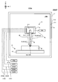
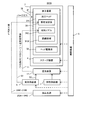
- FIG. 2 is a system configuration diagram showing a system configuration of the processing system of the first embodiment.
- FIG. 3 is a cross-sectional view showing the structure of the processing head (that is, the irradiation optical system and the material nozzle).
- FIG. 4 is a cross-sectional view showing the structure of the processing head (that is, the irradiation optical system and the material nozzle).
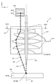
- FIG. 5 is a cross-sectional view showing an optical path of processing light in a virtual optical plane in the condensing optical system that intersects the optical axis of the condensing optical system.
- FIG. 1 is a cross-sectional view showing the structure of the processing system of the first embodiment.
- FIG. 2 is a system configuration diagram showing a system configuration of the processing system of the first embodiment.
- FIG. 3 is a cross-sectional view showing the structure of the processing head (that is, the irradi
- FIG. 6 is a cross-sectional view showing another example of the optical path of the processing light applied to the work through the condensing optical system.
- FIG. 7 is a cross-sectional view showing another example of a region through which the processing lights EL # 1 to EL # 4 pass in the optical surface OP.
- FIG. 8A is a plan view showing the processing light applied to the work
- FIG. 8B is a cross-sectional view showing the processing light applied to the work.
- FIG. 9A is a plan view showing the processing light applied to the work
- FIG. 9B is a cross-sectional view showing the processing light applied to the work.
- FIGS. 10 (a) to 10 (e) is a cross-sectional view showing a state in which a certain region on the work is irradiated with processing light and a modeling material is supplied.
- FIGS. 11 (a) to 11 (c) is a cross-sectional view showing a process of forming a three-dimensional structure.
- FIG. 12 is a plan view showing a target irradiation region (that is, an irradiation position of processing light) that moves toward the + Y side along the Y-axis direction on the modeling surface.
- a target irradiation region that is, an irradiation position of processing light
- FIGS. 15 (a) and 15 (b) are a cut-out view showing how the processing light EL is emitted toward the target irradiation region set on the modeling surface.
- FIG. 16 is a cross-sectional view showing an optical path of processing light in a virtual optical plane in the condensing optical system that intersects the optical axis of the condensing optical system.
- FIG. 17 is a plan view showing an example of a beam spot having a desired shape formed by a plurality of processing lights on the modeling surface).
- FIG. 18 is a cross-sectional view showing the structure of the processing system of the second embodiment.
- FIG. 19 is a system configuration diagram showing a system configuration of the processing system of the second embodiment.
- FIG. 20 is a cross-sectional view showing the optical paths of the measurement light and the object light in the irradiation optical system of the second embodiment (particularly in the condensing optical system).
- FIG. 21 is a cross-sectional view taken along the line XX-XX'of FIG.
- FIG. 22 is a system configuration diagram showing a system configuration of the processing system of the third embodiment.
- FIG. 23 is a cross-sectional view showing the structure of the irradiation optical system of the third embodiment.
- FIGS. 24 (a) to 24 (c) is a cross-sectional view showing an example of an optical path of measurement light applied to a modeling surface.
- FIG. 25 is a system configuration diagram showing a system configuration of the processing system of the fourth embodiment.
- FIG. 26 is a cross-sectional view showing the optical paths of the measurement light and the return light in the irradiation optical system of the fourth embodiment (particularly in the condensing optical system).
- FIG. 27 is a cross-sectional view taken along the line XXVI-XXVI'of FIG. 26.
- FIG. 28 is a system configuration diagram showing a system configuration of the processing system of the fifth embodiment.
- FIG. 29 is a plan view schematically showing the operation of the recovery device and the gas supply device of the fifth embodiment.
- FIG. 30 is a system configuration diagram showing a system configuration of the processing system of the sixth embodiment.
- FIG. 31 is a cross-sectional view showing the structure of the surrounding member of the sixth embodiment.
- FIG. 32 is a system configuration diagram showing a system configuration of the processing system of the seventh embodiment.
- FIG. 33 is a cross-sectional view showing the structure of the processing system of the seventh embodiment.
- each of the X-axis direction and the Y-axis direction is a horizontal direction (that is, a predetermined direction in the horizontal plane), and the Z-axis direction is a vertical direction (that is, a direction orthogonal to the horizontal plane). Yes, it is assumed that it is substantially in the vertical direction or the gravity direction).
- the rotation directions (in other words, the inclination direction) around the X-axis, the Y-axis, and the Z-axis are referred to as the ⁇ X direction, the ⁇ Y direction, and the ⁇ Z direction, respectively.
- the Z-axis direction may be the direction of gravity.
- the XY plane may be horizontal.
- the processing system SYS of the first embodiment First, the machining system SYS of the first embodiment (hereinafter, the machining system SYS of the first embodiment will be referred to as "machining system SYSA") will be described.
- the processing system SYSa of the first embodiment is a processing system capable of forming a three-dimensional structure ST by performing additional processing.
- the processing system SYSa can form a three-dimensional structure ST by performing additional processing based on, for example, a laser overlay welding method (LMD: Laser Metal Deposition).
- the laser overlay welding method (LMD) includes direct metal deposition, direct energy deposition, laser cladding, laser engineered net shaping, direct light fabrication, and laser consolidation.
- the processing system SYSa may form the three-dimensional structure ST by performing additional processing based on other additional processing methods.
- FIG. 1 is a cross-sectional view schematically showing the structure of the processing system SYSA of the first embodiment.
- FIG. 2 is a system configuration diagram showing a system configuration of the processing system SYSA of the first embodiment.
- the processing system SYSa is a three-dimensional structure (that is, a three-dimensional object having a size in any of the three-dimensional directions, and is a three-dimensional object, in other words, in the X-axis direction, the Y-axis direction, and the Z-axis direction.
- An object with a size) ST can be formed.
- the processing system SYSa can form the three-dimensional structure ST on the work W which is the basis (that is, the base material) for forming the three-dimensional structure ST.
- the processing system SYSa can form a three-dimensional structure ST by performing additional processing on the work W. When the work W is the stage 41 described later, the processing system SYSa can form the three-dimensional structure ST on the stage 41.
- the processing system SYSa can form a three-dimensional structure ST on the mounting object.
- the processing system SYSA may form a three-dimensional structure ST integrated with the mounted object.
- the operation of forming the three-dimensional structure ST integrated with the mounting object is equivalent to the operation of adding a new structure to the mounting object.
- the existing structure may be, for example, a repair-required product having a defective portion.
- the processing system SYSa may form a three-dimensional structure ST on the repair-required product so as to fill the defective portion of the repair-required product.
- the processing system SYSA may form a three-dimensional structure ST separable from the mounted object.
- the mounted object mounted on the stage 41 may be another three-dimensional structure ST (that is, an existing structure) formed by the processing system SYS.
- the work W is a mounting object mounted on the stage 41.
- the work W is a work W in which the three-dimensional structure ST is not formed and a work W in which at least a part of the three-dimensional structure ST is formed (that is, the work W).
- Both of the work W) including at least a part of the formed three-dimensional structure ST.
- the processing system SYSa can form a modeled object by the laser overlay welding method. That is, it can be said that the processing system SYSa is a 3D printer that forms an object by using the laminated modeling technique.
- the laminated molding technique may also be referred to as rapid prototyping, rapid manufacturing, or adaptive manufacturing.
- the processing system SYSa processes the modeling material M with the processing optical EL to form a modeled object.
- the modeling material M is a material that can be melted by irradiation with a processing light EL having a predetermined intensity or higher.
- a modeling material M for example, at least one of a metallic material and a resin material can be used.
- the modeling material M a material different from the metallic material and the resin material may be used.
- the modeling material M is a powdery or granular material. That is, the modeling material M is a powder or granular material.
- the modeling material M does not have to be a powder or granular material.
- at least one of a wire-shaped modeling material and a gaseous modeling material may be used.
- the processing system SYSa has a material supply source 1, a plurality of processing light sources 2, a processing device 3, a stage device 4, and a gas, as shown in FIGS. 1 and 2.
- a supply source 5 and a control device 6 are provided.
- the processing device 3 and the stage device 4 may be housed in the chamber space 73IN inside the housing 7.
- the material supply source 1 supplies the modeling material M to the processing device 3.
- the material supply source 1 is formed in a desired amount according to the required amount so that the amount of the modeling material M required per unit time for forming the three-dimensional structure ST is supplied to the processing apparatus 3. Supply material M.
- Each of the plurality of processed light sources 2 emits, for example, at least one of infrared light, visible light, and ultraviolet light as processed light EL.
- the processed light EL may include pulsed light (that is, a pulse beam).
- the processing light EL may be laser light.
- each of the plurality of processing light sources 2 may include a laser light source (for example, a semiconductor laser such as a laser diode (LD)).
- the laser light source may include at least one such as a fiber laser, a CO 2 laser, a YAG laser and an excimer laser.
- the processing light EL does not have to be laser light.
- the processing light source 2 that emits the processing light EL that is not the laser light may include an arbitrary light source (for example, at least one such as an LED (Light Emitting Side) and a discharge lamp).
- the processing system SYSA emits four processing light sources 2 (specifically, processing light source 2 # 1 that emits processing light EL # 1 and processing light source 2 # 2 that emits processing light EL # 2.
- processing light source 2 # 1 that emits processing light EL # 1
- processing light source 2 # 2 that emits processing light EL # 2.
- An example including a processing light source 2 # 3 for emitting the processing light EL # 3 and a processing light source 2 # 4 will be described.
- the number of the processing light sources 2 may be 3 or less, or 5 or more.
- the processing apparatus 3 processes the modeling material M supplied from the material supply source 1 by using the processing lights EL # 1 to EL # 4 propagating from the processing light sources 2 # 1 to 2 # 4, respectively.
- a three-dimensional structure ST is formed.
- the processing apparatus 3 includes a processing head 31 and a head drive system 32.
- the processing device 3 does not have to include the head drive system 32.
- the processing head 31 includes an irradiation optical system 311 and a material nozzle (that is, a material supply device for supplying the modeling material M) 312.
- the processing head 31 and the head drive system 32 are housed in the chamber space 73IN.
- at least a part of the processing head 31 and / or the head drive system 32 may be arranged in the external space 74OUT, which is the space outside the housing 7.
- the external space 74OUT may be a space accessible to the operator of the processing system SYS.
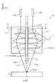
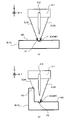
- FIGS. 3 and 4 are cross-sectional views showing the structure of the processing head 31 (that is, the irradiation optical system 311 and the material nozzle 312).
- the irradiation optical system 311 is an optical system in which the processing lights EL # 1 to EL # 4 propagating from the processing light sources 2 # 1 to 2 # 4, respectively, are incident.
- the irradiation optical system 311 is an optical system for emitting EL # 4 from the processed light EL # 1 incident on the irradiation optical system 311.
- the irradiation optical system 311 is optically connected to the processing light sources 2 # 1 to 2 # 4 via a plurality of optical transmission members 21 including at least one such as an optical fiber and a light pipe. ..
- the irradiation optical system 311 is optically connected to the processing light source 2 # 1 via the optical transmission member 21 # 1 and optically via the processing light source 2 # 2 and the optical transmission member 21 # 2. Is optically connected to the processing light source 2 # 3 via the optical transmission member 21 # 3, and is optically connected to the processing light source 2 # 4 via the optical transmission member 21 # 4.
- the irradiation optical system 311 emits EL # 4 from the processed light EL # 1 propagating from the processed light sources 2 # 1 to 2 # 4 via the optical transmission members 21 # 1 to 21 # 4.
- the irradiation optical system 311 emits EL # 4 from the processing light EL # 1 toward the lower side (that is, the ⁇ Z side) from the irradiation optical system 311.
- a stage 41 is arranged below the irradiation optical system 311. When the work W is placed on the stage 41, the irradiation optical system 311 emits EL # 4 from the processing light EL # 1 toward the work W.
- the irradiation optical system 311 may condense the processed light EL # 1 to EL # 4 emitted toward the work W on the work W.
- the irradiation optical system 311 may include a condensing optical system 3111.
- the condensing optical system 3111 is an optical system including a plurality of optical members 3112 (for example, a lens), but may be an optical system including a single optical member 3112.
- the processed light EL # 1 to EL # 4 are used in the optical path of the processed light EL # 1 to EL # 4 among the plurality of optical members 3112 (particularly, the plurality of optical members 3112 having power) included in the condensing optical system 3111.
- the terminal optical member 3114 may be referred to as a final optical member.
- the processed lights EL # 1 to EL # 4 emitted from the condensing optical system 3111 are virtual optical surfaces that intersect the optical axis AX of the condensing optical system 3111 (that is, the optical axis of the irradiation optical system 311).
- the light is focused on the light collecting surface FP. Therefore, the condensing optical system 3111 condenses the processed light EL # 1 to EL # 4 incident on the pupil surface (incident pupil surface) of the condensing optical system 3111 on the condensing surface FP of the condensing optical system 3111. It may also be regarded as an optical system for doing so.
- the processed light EL # 1 to EL # 4 are superimposed on the condensing surface FP. It may mean the state of "light”. That is, in the state of "the processed light EL # 1 to EL # 4 is focused on the condensing surface FP" in the first embodiment, "the processed light EL # 1 to EL # 4 are at the same position on the condensing surface FP". It may mean a state of being "irradiated with light”.
- Such a condensing surface FP is typically set at the rear focal position of the condensing optical system 3111. Note that FIGS.
- the condensing surface FP matches the surface WS of the work W.
- the condensing surface FP is a surface intersecting the Z axis (for example, a surface along the XY plane).
- the entrance pupil surface of the condensing optical system 3111 is located on the outside (incident side) of the condensing optical system 3111, but the entrance pupil surface of the condensing optical system 3111 is the condensing optical system 3111. It may be located inside the.
- the optical paths of the processed light EL # 1 to EL # 4 may be optically separated. That is, in the condensing optical system 3111, the optical paths of the processed lights EL # 1 to EL # 4 may be different from each other. In the condensing optical system 3111, the optical paths of the processed lights EL # 1 to EL # 4 do not have to overlap each other.
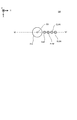
- a virtual optical surface OP in the condensing optical system 3111 intersecting the optical axis AX of the condensing optical system 3111. Is a surface along the XY plane, for example, as shown in FIG. 5, which is a cross-sectional view showing the optical paths of the processed light EL # 1 to EL # 4 in the incident pupil surface of the condensing optical system 3111.
- the processed lights EL # 1 to EL # 4 may each pass through different regions separated from the optical axis AX in different directions.
- the distance between the optical path of # 3 and the distance between the optical axis AX and the optical path of the processed optical EL # 4 may be the same as each other.
- the distances between the optical axis AX and at least two optical paths of the processed light EL # 1 to EL # 4 may be different from each other. In the examples shown in FIGS.
- the distances between the optical axis AX and the optical paths of the processed light EL # 1 to EL # 4 are the same in the optical surface OP.
- the processed light EL # 1 to EL # 4 have a region symmetrical with respect to the optical axis AX in the optical surface OP (a region rotationally symmetric n times with respect to the optical axis AX in the optical surface OP (however, n is 2 or more). Integer)) may be passed.
- the processed optics EL # 1 to EL # 4 have a rotation angle of 270 in the clockwise direction about the origin in the coordinate plane along the XY plane with the optical axis AX as the origin.
- the condensing optical system 3111 When the processing light EL # 1 to EL # 4 pass through different regions separated from each other in different directions from the optical axis AX in the optical surface OP, the condensing optical system 3111 is subjected to processing light EL # 1 to EL.
- the work W may be irradiated with # 4 from different directions. Specifically, as shown in FIGS. 3 to 5, the condensing optical system 3111 transfers the processing light EL # 1 to EL # 4 to the work W from different positions in the rotation direction about the optical axis AX. You may irradiate.
- FIG. 6 is a cross-sectional view showing another example of the optical path of the processed light EL # 1 to EL # 4 irradiated to the work W via the condensing optical system 3111, and the processed light EL # 1 in the optical surface OP. As shown in FIG.
- the processing light EL # 1 to EL # 4 are separated from the optical axis AX by different distances toward the + Y side. It may pass through different areas. That is, the processing light EL # 1 to EL # 4 are the distance between the optical axis AX and the optical path of the processing light EL # 1, the distance between the optical axis AX and the optical path of the processing light EL # 2, and the optical axis AX.
- the condensing optical system 3111 has a condensing optical system 3111.
- the work W is irradiated with the processing lights EL # 1 to EL # 4 so that the angles formed by the traveling directions of the processing lights EL # 1 to EL # 4 and the optical axis AX traveling from the processing light EL # 1 to the work W are different from each other. It is also good. Specifically, as shown in FIG.
- the traveling direction of the processing light EL # 1 and the angle formed by the optical axis AX, and the traveling direction of the processing light EL # 2 and the optical axis AX are different.
- the processing light EL # 1 to EL # so that the angle formed, the angle formed by the traveling direction of the processing light EL # 3 and the optical axis AX, and the angle formed by the traveling direction of the processing light EL # 4 and the optical axis AX are different from each other. 4 may be irradiated to the work W.
- the XY at the ejection ends of the optical transmission members 21 # 1 to 21 # 4 The position along the plane (the plane parallel to the optical plane OP) may be changeable. Further, the positions of the ejection ends of the optical transmission members 21 # 1 to 21 # 4 along the Z direction may also be changed. Further, the processing light emitted from the optical transmission members 21 # 1 to 21 # 4 is the traveling direction of the processing light EL # 1 to EL # 4 (the processing light between the optical transmission members 21 # 1 to 21 # 4 and the condensing optical system). The traveling direction of EL # 1 to EL # 4) may also be changed.
- Each optical member 3112 constituting the condensing optical system 3111 is formed with an opening 3113 that penetrates each optical member 3112 in the direction along the optical axis AX.
- the opening 3113 may be formed at a position where each optical member 3112 and the optical axis AX overlap. That is, the opening 3113 may be formed on the optical axis AX.
- At least a part of the material nozzle 312 is arranged in the plurality of openings 3113 formed in the plurality of optical members 3112, respectively. At least a part of the material nozzle 312 is inserted into the plurality of openings 3113.
- the material nozzle 312 may be inserted into the opening 3113 so that the supply outlet 314 at the tip of the material nozzle 312 is arranged outside the opening 3113. Therefore, the material nozzle 312 is arranged so that at least a part of the material nozzle 312 is surrounded by a plurality of optical members 3112.
- the openings 3113 are formed on the optical axis AX
- at least a part of the material nozzles 312 may be arranged along the optical axis AX in the plurality of openings 3113. In this case, at least a part of the material nozzle 312 may be arranged on the optical axis AX.
- the processed light EL # 1 to EL # 4 pass through a portion of each optical member 3112 in which the opening 3113 is not formed.
- the processed light EL # 1 to EL # 4 pass through a portion of each optical member 3112 that is separated from the optical axis AX.
- the processing light EL # 1 to EL # 4 may travel from the condensing optical system 3111 toward the work W along a direction inclined with respect to the optical axis AX. That is, the condensing optical system 3111 may emit the processing light EL # 1 to EL # 4 along the direction inclined with respect to the optical axis AX.
- the purge gas supplied from the gas supply source 5 to the chamber space 73IN passes through the opening 3113 to the space on the injection surface side of the terminal optical member 3114 (that is, the work). It may be supplied to the space on the W side).
- the purge gas supplied from the gas supply source 5 to the chamber space 73IN may be supplied between a plurality of optical members 3112 constituting the condensing optical system 3111.
- the purge gas supplied between the plurality of optical members 3112 constituting the condensing optical system 3111 passes through the opening 3113 (particularly, the opening 3113 of the terminal optical member 3114) into the space on the injection surface side of the terminal optical member 3114. It may be supplied.
- a supply outlet 314 is formed in the material nozzle 312.
- the material nozzle 312 supplies the molding material M from the supply outlet 314 (eg, ejects, ejects, ejects, or sprays).
- the material nozzle 312 is physically connected to the material supply source 1 which is the supply source of the modeling material M via the supply pipe 11 and the mixing device 12.
- the material nozzle 312 supplies the modeling material M supplied from the material supply source 1 via the supply pipe 11 and the mixing device 12.
- the material nozzle 312 may pump the modeling material M supplied from the material supply source 1 via the supply pipe 11.
- the modeling material M from the material supply source 1 and the transporting gas (that is, the pumping gas, that is, an inert gas such as nitrogen or argon) are mixed by the mixing device 12 and then the supply pipe 11 is connected. It may be pumped to the material nozzle 312 via. As a result, the material nozzle 312 supplies the modeling material M together with the conveying gas.
- the transporting gas for example, purge gas supplied from the gas supply source 5 is used.
- a gas supplied from a gas supply source different from the gas supply source 5 may be used.
- the material nozzle 312 is drawn in a tubular shape in FIGS. 3 to 4, the shape of the material nozzle 312 is not limited to this shape.
- the material nozzle 312 supplies the modeling material M downward (that is, the ⁇ Z side) from the material nozzle 312. At this time, since the material nozzle 312 is arranged in the opening 3113 of the optical member 3112, the material nozzle 312 passes the modeling material M through the opening 3113 of the optical member 3112 (particularly, the opening 3113 of the terminal optical member 3114). It may be considered as supplying.
- the material nozzle 312 supplies the modeling material M through the space inside the optical path of the processing light EL # 1 to EL # 4 emitted through the portion of the optical member 3112 where the opening 3113 is not formed. It may be considered that there is.
- a stage 41 is arranged below the material nozzle 312. When the work W is mounted on the stage 41, the material nozzle 312 supplies the modeling material M toward the work W or the vicinity of the work W.
- the material nozzle 312 supplies the modeling material M to the work W from the direction intersecting the surface WS of the work W.
- the material nozzle 312 supplies the modeling material M to the work W from the Z-axis direction intersecting the surface WS of the work W. That is, the material nozzle 312 supplies the modeling material M so that the supply path of the modeling material M from the material nozzle 312 to the work W is a path along the Z-axis direction.
- the condensing optical system 3111 performs the processing light EL.
- the supply direction of the modeling material M by the material nozzle 312 (which may be referred to as the material supply direction) may be different from the irradiation direction of the processing light EL # 1 to EL # 4 by the condensing optical system 3111.
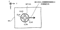
- the material nozzle 312 irradiates the target irradiation region EA in which the irradiation optical system 311 irradiates the processing light EL # 1 to EL # 4 (that is, the irradiation optical system 311 irradiates the processing light EL # 1 to EL # 4). It is aligned with the irradiation optical system 311 so as to supply the modeling material M toward the position (position). That is, the target supply region MA and the target irradiation region EA, which are set on or near the work W as the region where the material nozzle 312 supplies the modeling material M, coincide with (or at least partially overlap).
- the material nozzle 312 and the irradiation optical system 311 are aligned. Further, as will be described later, a molten pool MP is formed on the work W by the processing lights EL # 1 to EL # 4 emitted from the irradiation optical system 311.
- the material nozzle 312 may be aligned with the irradiation optical system 311 so as to supply the modeling material M to the molten pool MP. However, the material nozzle 312 does not have to supply the modeling material M to the molten pool MP.
- the modeling material M from the material nozzle 312 is melted by the processing light EL # 1 to EL # 4 from the irradiation optical system 311 before reaching the work W, and the molten modeling is performed.
- the material M may be attached to the work W.
- the opening 3113 in which the material nozzle 312 is arranged is used as a supply path for the purge gas supplied to the space on the injection surface side of the terminal optical member 3114.
- the purge gas supplied through the opening 3113 forms, for example, a gas flow toward the supply outlet 314 at the tip of the material nozzle 312.
- a gas flow increases the possibility that the modeling material M from the supply outlet 314 will be supplied along the downward supply path from the material nozzle 312. That is, the possibility that the modeling material M from the supply outlet 314 is scattered in all directions from the material nozzle 312 is reduced.
- the material nozzle 312 can appropriately supply the modeling material M. That is, the processing system SYSa can improve the directivity of the modeling material M in the supply direction.
- the head drive system 32 moves the processing head 31.
- the head drive system 32 moves the machining head 31 along at least one of the X-axis, the Y-axis, the Z-axis, the ⁇ X direction, the ⁇ Y direction, and the ⁇ Z direction, for example.
- the relative positions of the machining head 31 and the work W mounted on the stage 41 and the stage 41 change. That is, the relative positions of the irradiation optical system 311 and the material nozzle 312 and the stage 41 and the work W are changed.
- the head drive system 32 may function as a moving device for moving the target irradiation region EA and the target supply region MA (further, the molten pool MP) with respect to the work W.
- the head drive system 32 moves the processing head 31 along the Z-axis direction (that is, the direction along the optical axis AX of the condensing optical system 3111), the processing light EL # 1 to EL # 4 are condensed.
- the distance DS between the condensing surface FP of the condensing optical system 3111 and the surface WS of the work W changes. Therefore, the head drive system 32 may function as a distance changing device for changing the distance DS between the condensing surface FP of the condensing optical system 3111 and the surface WS of the work W in the Z-axis direction.
- the head drive system 32 collects light in the Z-axis direction so that the light-collecting surface FP of the light-collecting optical system 3111 coincides with the surface WS of the work W (or the modeling surface MS described later, the same applies hereinafter) in the Z-axis direction.
- the distance DS between the surface FP and the surface WS of the work W may be changed. That is, the head drive system 32 may change the distance DS so that the distance DS becomes zero.
- FIG. 8A is a plan view showing the processing lights EL # 1 to EL # 4 irradiated on the work W, and a cross-sectional view showing the processing lights EL # 1 to EL # 4 irradiated on the work W. As shown in FIG.
- the processing lights EL # 1 to EL # 4 are focused on the surface WS of the work W. That is, the processing lights EL # 1 to EL # 4 are superimposed on the surface WS of the work W. In this case, a single beam spot irradiated with the processing light EL # 1 to EL # 4 is formed on the surface WS of the work W.
- the distance between the condensing surface FP and the surface WS of the work W in the Z-axis direction is such that the condensing surface WS of the condensing optical system 3111 deviates from the surface WS of the work W in the Z-axis direction.
- FIG. 9A is a plan view showing the processing lights EL # 1 to EL # 4 irradiated on the work W, and a cross-sectional view showing the processing lights EL # 1 to EL # 4 irradiated on the work W. As shown in FIG.
- the processing lights EL # 1 to EL # 4 are not focused on the surface WS of the work W. That is, the processing light EL # 1 to EL # 4 are not superimposed on the surface WS of the work W.
- four beam spots irradiated with the processing lights EL # 1 to EL # 4 are formed on the surface WS of the work W.
- the positional relationship of the four beam spots and the size of the four beam spots change depending on the distance between the focusing surface of the focusing optical system 3111 and the surface of the work W in the Z-axis direction.
- the four beam spots do not overlap each other, but at least two of the four beam spots may partially overlap. Further, in the examples shown in FIGS.
- the processing lights EL # 1 to EL # 4 do not intersect with each other, but after the processing lights EL # 1 to EL # 4 intersect with each other, they intersect with each other.
- the processing light EL # 1 to EL # 4 may be applied to the surface WS of the work W in a separated state.
- the head drive system 32 may function as a device for changing the distribution (for example, intensity distribution) of the processing light EL # 1 to EL # 4 on the surface WS of the work W.
- the stage device 4 includes a stage 41 and a stage drive system 42. However, the stage device 4 does not have to include the stage drive system 42.
- the stage 41 may be referred to as a table.
- Stage 41 can support work W.
- the state in which the work W supports the work W may mean a state in which the work W is directly or indirectly supported by the stage 41.
- the stage 41 may be able to hold the work W placed on the stage 41. That is, the stage 41 may support the work W by holding the work W.
- the stage 41 may be provided with a mechanical chuck, a vacuum suction chuck, or the like in order to hold the work W.
- the stage 41 does not have to be able to hold the work W.
- the work W may be mounted on the stage 41 without being clamped. Further, the stage 41 may be able to release the held work W when the work W is held.
- the irradiation optical system 311 described above irradiates the work W with the processing lights EL # 1 to EL # 4 during at least a part of the period in which the stage 41 supports the work W. Further, the material nozzle 312 described above supplies the modeling material M for at least a part of the period during which the stage 41 supports the work W.
- the stage drive system 42 moves the stage 41. Therefore, the stage drive system 42 may be referred to as a mobile device.
- the stage drive system 42 moves the stage 41 along at least one of the X-axis, the Y-axis, the Z-axis, the ⁇ X direction, the ⁇ Y direction, and the ⁇ Z direction, for example.
- the stage drive system 42 moves the stage 41, the relative positions of the processing head 31 and the work W mounted on the stage 41 and the stage 41 change. Therefore, the stage drive system 42 functions as a moving device for moving the target irradiation region EA and the target supply region MA (furthermore, the molten pool MP) relative to the work W, similarly to the head drive system 32. You may.
- the stage drive system 42 moves the stage 41 along the Z-axis direction (that is, the direction along the optical axis AX of the focusing optical system 3111), the processing light EL # 1 to EL # 4 are focused.
- the distance DS between the condensing surface FP of the condensing optical system 3111 and the surface WS of the work W changes. Therefore, the stage drive system 42, like the head drive system 32, changes the distance DS for changing the distance DS between the condensing surface FP of the condensing optical system 3111 and the surface WS of the work W in the Z-axis direction. It may function as a device. Similar to the head drive system 32, the stage drive system 42 may function as a device for changing the distribution (for example, intensity distribution) of the processing light EL # 1 to EL # 4 on the surface WS of the work W.
- the gas supply source 5 is a supply source of purge gas for purging the chamber space 73IN.
- the purge gas contains an inert gas.
- the inert gas nitrogen gas or argon gas can be mentioned.
- the gas supply source 5 is connected to the chamber space 73IN via a supply port 72 formed in the partition member 71 of the housing 7 and a supply pipe 51 connecting the gas supply source 5 and the supply port 72.
- the gas supply source 5 supplies purge gas to the chamber space 73IN via the supply pipe 51 and the supply port 72.
- the chamber space 73IN becomes a space purged by the purge gas.
- the gas supply source 5 may be a cylinder in which an inert gas such as nitrogen gas or argon gas is stored.
- the inert gas is nitrogen gas
- the gas supply source 5 may be a nitrogen gas generator that generates nitrogen gas from the atmosphere as a raw material.
- the gas supply source 5 may supply the purge gas to the mixing device 12 to which the modeling material M from the material supply source 1 is supplied. good.
- the gas supply source 5 may be connected to the mixing device 12 via a supply pipe 52 that connects the gas supply source 5 and the mixing device 12.
- the gas supply source 5 supplies the purge gas to the mixing device 12 via the supply pipe 52.
- the modeling material M from the material supply source 1 is supplied toward the material nozzle 312 through the supply pipe 11 by the purge gas supplied from the gas supply source 5 via the supply pipe 52 (specifically,). , Pumped).
- the gas supply source 5 may be connected to the material nozzle 312 via the supply pipe 52, the mixing device 12, and the supply pipe 11. In that case, the material nozzle 312 will supply the modeling material M together with the purge gas for pumping the modeling material M from the supply outlet 314.
- the control device 6 controls the operation of the processing system SYS.
- the control device 6 may include, for example, an arithmetic unit and a storage device.
- the arithmetic unit may include, for example, at least one of a CPU (Central Processing Unit), a GPU (Graphics Processing Unit), and an FPGA (Field Programmable Gate Array).
- the storage device may include, for example, a memory.
- the control device 6 functions as a device that controls the operation of the processing system SYS by executing a computer program by the arithmetic unit.
- This computer program is a computer program for causing the arithmetic unit to perform (that is, execute) the operation described later to be performed by the control device 6.
- this computer program is a computer program for causing the control device 6 to function so that the processing system SYSa performs an operation described later.
- the computer program executed by the arithmetic unit may be recorded in a storage device (that is, a recording medium) included in the control device 6, or any storage built in the control device 6 or externally attached to the control device 6. It may be recorded on a medium (for example, a hard disk or a semiconductor memory). Alternatively, the arithmetic unit may download the computer program to be executed from an external device of the control device 6 via the network interface.
- the control device 6 may control the emission mode of the processed light EL # 1 to EL # 4 by the irradiation optical system 311.
- the injection mode may include, for example, at least one of the intensity of the processing light EL # 1 to EL # 4 and the injection timing of the processing light EL # 1 to EL # 4.
- the emission modes are, for example, the emission time of the pulsed light, the emission period of the pulsed light, and the length of the emission time of the pulsed light and the pulsed light. It may include at least one of the ratios (so-called duty ratios) to the light emission period of.
- control device 6 may control the movement mode of the processing head 31 by the head drive system 32.
- the control device 6 may control the movement mode of the stage 41 by the stage drive system 42.
- the movement mode may include, for example, at least one of a movement amount, a movement speed, a movement direction, and a movement timing (movement timing).
- the control device 6 may control the supply mode of the modeling material M by the material nozzle 312.
- the supply mode may include, for example, at least one of a supply amount (particularly, a supply amount per unit time) and a supply timing (supply timing).
- the control device 6 does not have to be provided inside the processing system SYS.
- the control device 6 may be provided as a server or the like outside the processing system SYS.
- the control device 6 and the processing system SYSA may be connected by a wired and / or wireless network (or a data bus and / or a communication line).
- a wired network for example, a network using a serial bus type interface represented by at least one of IEEE1394, RS-232x, RS-422, RS-423, RS-485 and USB may be used.
- a network using a parallel bus interface may be used.
- a network using an Ethernet (registered trademark) compliant interface represented by at least one of 10BASE-T, 100BASE-TX and 1000BASE-T may be used.
- a network using radio waves may be used.
- An example of a network using radio waves is a network conforming to IEEE802.1x (for example, at least one of wireless LAN and Bluetooth®).
- a network using infrared rays may be used.
- a network using optical communication may be used.
- the control device 6 and the processing system SYSA may be configured so that various types of information can be transmitted and received via the network.
- control device 6 may be able to transmit information such as commands and control parameters to the processing system SYSA via the network.
- the processing system SYSa may include a receiving device that receives information such as commands and control parameters from the control device 6 via the network. Even if the processing system SYSa is provided with a transmission device (that is, an output device that outputs information to the control device 6) that transmits information such as commands and control parameters to the control device 6 via the network. good.
- a transmission device that is, an output device that outputs information to the control device 6
- the second control device that performs the other part of the processing performed by the control device 6 is provided.
- the control device may be provided outside the processing system SYS.
- the recording medium for recording the computer program executed by the control device 6 includes a CD-ROM, a CD-R, a CD-RW, a flexible disk, an MO, a DVD-ROM, a DVD-RAM, a DVD-R, a DVD + R, and a DVD.
- -Used by at least one of optical disks such as RW, DVD + RW and Blu-ray (registered trademark), magnetic media such as magnetic tape, magneto-optical disks, semiconductor memories such as USB memory, and other media capable of storing programs. May be done.
- the recording medium may include a device capable of recording a computer program (for example, a general-purpose device or a dedicated device in which the computer program is implemented in a state in which it can be executed in at least one form such as software and firmware).
- each process or function included in the computer program may be realized by a logical processing block realized in the control device 6 by the control device 6 (that is, the computer) executing the computer program. It may be realized by hardware such as a predetermined gate array (FPGA, ASIC) included in the control device 6, or a logical processing block and a partial hardware module that realizes a part of the hardware are mixed. It may be realized in the form of.
- the housing 7 is a storage device that accommodates at least a part of each of the processing device 3 and the stage device 4 in the chamber space 73IN, which is the internal space of the housing 7.
- the housing 7 includes a partition member 71 that defines the chamber space 73IN.
- the partition member 71 is a member that separates the chamber space 73IN from the external space 74OUT of the housing 7.
- the partition member 71 faces the chamber space 73IN via its inner wall 711 and faces the outer space 74OUT via its outer wall 712. In this case, the space surrounded by the partition member 71 (more specifically, the space surrounded by the inner wall 711 of the partition member 71) becomes the chamber space 73IN.
- the partition member 71 may be provided with a door that can be opened and closed.
- This door may be opened when the work W is placed on the stage 41.
- the door may be opened when the work W and / or the modeled object is taken out from the stage 41.
- the door may be closed during processing (ie, during additional processing or joining processing).
- An observation window (not shown) for visually recognizing the chamber space 73IN from the external space 74OUT of the housing 7 may be provided on the partition wall member 71.
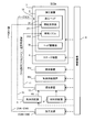
- the machining system SYSa performs an additional machining operation for forming the three-dimensional structure ST on the work W. Further, the processing system SYSa performs an optical characteristic control operation for controlling at least one characteristic of the processing light EL # 1 to the processing light EL # 4 during at least a part of the period during which the additional processing operation is performed. Therefore, in the following, the additional processing operation and the optical characteristic control operation will be described in order.
- (1-2-1) Addition processing operation First , the addition processing operation will be described. As described above, the processing system SYSa forms the three-dimensional structure ST by the laser overlay welding method.
- the processing system SYSA may form the three-dimensional structure ST by performing an existing additional processing operation (in this case, a modeling operation) based on the laser overlay welding method.
- an existing additional processing operation in this case, a modeling operation
- the laser overlay welding method may form the three-dimensional structure ST by performing an existing additional processing operation (in this case, a modeling operation) based on the laser overlay welding method.
- the processing system SYSa forms the three-dimensional structure ST on the work W based on the three-dimensional model data (for example, CAD (Computer Aided Design) data) of the three-dimensional structure ST to be formed.
- the three-dimensional model data for example, CAD (Computer Aided Design) data
- the processing system SYSa sequentially forms, for example, a plurality of layered partial structures (hereinafter, referred to as “structural layers”) SLs arranged along the Z-axis direction.
- the processing system SYSa sequentially forms a plurality of structural layers SL obtained by cutting the three-dimensional structure ST into round slices along the Z-axis direction.
- a three-dimensional structure ST which is a laminated structure in which a plurality of structural layers SL are laminated, is formed.
- the flow of the operation of forming the three-dimensional structure ST by sequentially forming the plurality of structural layers SL one by one will be described.
- the processing system SYSa processes the target irradiation region EA under the control of the control device 6 so that the target irradiation region EA is set in the desired region on the modeling surface MS corresponding to the surface WS of the work W or the surface of the formed structural layer SL. At least one of the head 31 and the stage 41 is moved. After that, the processing system SYSa irradiates the target irradiation region EA with the processing light EL # 1 to EL # 4 from the irradiation optical system 311.
- the condensing surface FP on which the processing light EL # 1 to EL # 4 are focused in the Z-axis direction may coincide with the modeling surface MS (FIGS. 8A and 8B). reference).
- the condensing surface FP on which the processing light EL # 1 to EL # 4 are focused in the Z-axis direction may be deviated from the modeling surface MS (see FIGS. 9A and 9B). ..
- a molten pool a molten pool ( That is, a pool of metal melted by the processing light EL # 1 to EL # 4) MP is formed.
- the processing system SYSa supplies the modeling material M from the material nozzle 312 under the control of the control device 6.
- the target supply region MA to which the modeling material M is supplied coincides with the target irradiation region EA as described above, the target supply region MA includes at least a part of the region where the molten pool MP is formed. .. Therefore, as shown in FIG. 10B, the processing system SYSa supplies the modeling material M to the molten pool MP from the material nozzle 312. As a result, the modeling material M supplied to the molten pool MP is melted.
- the molding material M melted in the molten pool MP is cooled and solidified (that is, solidified). ..
- the solidified modeling material M is deposited on the modeling surface MS. That is, a modeled object is formed by the deposit of the solidified modeling material M.
- the processing system SYSa is capable of forming a molten pool MP by irradiating the processing light EL # 1 to EL # 4, supplying the modeling material M to the molten pool MP, melting the supplied modeling material M, and melting the molten modeling material.
- a series of modeling processes including solidification of M is repeated while moving the processing head 31 relative to the modeling surface MS along the XY plane.
- the processing system SYS irradiates the area on the modeling surface MS on which the modeled object is to be formed with the processing light EL # 1 to EL # 4, while processing the area on the modeling surface MS where the modeled object is not desired to be formed. Do not irradiate EL # 1 to EL # 4.
- the processing system SYSa moves the target irradiation region EA along the predetermined movement locus on the modeling surface MS, and the processing light EL # 1 to EL at the timing corresponding to the distribution mode of the region where the modeled object is to be formed. Irradiate the modeling surface MS with # 4.
- the molten pool MP also moves on the modeling surface MS along the movement locus according to the movement locus of the target irradiation region EA.
- the molten pool MP is sequentially formed on the modeling surface MS in the portion of the region along the movement locus of the target irradiation region EA that is irradiated with the processing light EL # 1 to EL # 4.
- a structural layer SL corresponding to an aggregate of the modeled objects made of the modeling material M that has been melted and then solidified is formed on the modeling surface MS. That is, the structural layer SL corresponding to the aggregate of the shaped objects formed on the modeling surface MS in the pattern corresponding to the moving locus of the molten pool MP (that is, the shape corresponding to the moving locus of the molten pool MP in a plan view).
- the structural layer SL) to have is formed.
- the supply may be stopped. Further, when the target irradiation region EA is set in the region where the modeled object is not to be formed, the processing system SYSa supplies the modeling material M to the target irradiation region EA, and at the same time, the processing light having an intensity that does not allow the molten pool MP to be formed. EL # 1 to EL # 4 may be applied to the target irradiation region EA.
- the processing system SYSa repeatedly performs the operation for forming such a structural layer SL under the control of the control device 6 based on the three-dimensional model data. Specifically, first, the control device 6 creates slice data by slicing the three-dimensional model data at a stacking pitch. Note that data obtained by partially modifying this slice data may be used according to the characteristics of the processing system SYS.
- the processing system SYSa performs an operation for forming the first structural layer SL # 1 on the modeling surface MS corresponding to the surface WS of the work W with three-dimensional model data corresponding to the structural layer SL # 1 (that is, that is). This is performed based on the slice data corresponding to the structural layer SL # 1.
- the structural layer SL # 1 is formed on the modeling surface MS as shown in FIG. 11A.
- the processing system SYS sets the surface (that is, the upper surface) of the structural layer SL # 1 on the new modeling surface MS, and then forms the second structural layer SL # 2 on the new modeling surface MS. do.
- the control device 6 first controls the head drive system 32 so that the machining head 31 moves along the Z axis. Specifically, the control device 6 controls the head drive system 32 so that the target irradiation region EA and the target supply region MA are set on the surface of the structural layer SL # 1 (that is, the new modeling surface MS). The machining head 31 is moved toward the + Z side.
- the processing system SYSa operates on the structural layer SL # 1 based on the slice data corresponding to the structural layer SL # 2 in the same operation as the operation of forming the structural layer SL # 1 under the control of the control device 6.
- the structural layer SL # 2 is formed on the surface.
- the structural layer SL # 2 is formed.
- the same operation is repeated until all the structural layers SL constituting the three-dimensional structure ST to be formed on the work W are formed.
- the three-dimensional structure ST is formed by the laminated structure in which a plurality of structural layers SL are laminated.
- the optical characteristic control operation is mainly performed under the control of the control device 6. That is, the control device 6 controls (in other words, changes or changes) at least one characteristic of the processing light EL # 1 to EL # 4 during at least a part of the period during which the additional processing operation is performed by performing the optical characteristic control operation. Adjustment) may be performed.
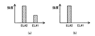
- the control device 6 may individually control at least one characteristic of the processing light EL # 1 to EL # 4. That is, the control device 6 controls the characteristics of the processing light EL of one of the processing lights EL # 1 to EL # 4 and the characteristics of the other processing light EL of the processing lights EL # 1 to EL # 4. It may or may not be controlled. At this time, the control device may control the respective characteristics of the processing light EL # 1 to EL # 4. That is, the control device controls the characteristics of the processing light EL # 1, controls the characteristics of the processing light EL # 2, controls the characteristics of the processing light EL # 3, and controls the characteristics of the processing light EL # 4. May be good.
- control device may control at least one characteristic of the processing light EL # 1 to the processing light EL # 4, while not controlling at least one other characteristic of the processing light EL # 1 to EL # 4. good. That is, the control device 6 may control at least one characteristic of the processing light EL # 1 to EL # 4, while fixing at least one other characteristic of the processing light EL # 1 to EL # 4. For example, the control device 6 controls the characteristics of the processing light EL # 1 and EL # 2, but does not have to control the characteristics of the processing light EL # 3 and EL # 4 (fixed). May be good).
- the control device 6 has the processing light EL # 1 so that at least one characteristic of the processing light EL # 1 to EL # 4 is different from at least one characteristic of the processing light EL # 1 to EL # 4. At least one characteristic of EL # 4 may be controlled from. In other words, the control device 6 makes the processing light different from at least one characteristic of the processing light EL # 1 to EL # 4 from at least one other characteristic of the processing light EL # 1 to EL # 4. At least one characteristic of EL # 1 to EL # 4 may be set (in other words, determined). In this case, the control device 6 controls at least one characteristic of the processing light EL # 1 to EL # 4 so that at least one characteristic of the processing light EL # 1 to EL # 4 becomes the set characteristic.
- control device 6 sets the characteristics of the processing light EL # 1 so that the characteristics of the processing light EL # 1 are different from the characteristics of the processing light EL # 2 to EL # 4, and sets the characteristics of the processing light EL # 1.
- the characteristic of the processing light EL # 1 may be controlled so that the characteristic of # 1 becomes the set characteristic.
- the characteristics of the processed light EL may include the strength of the processed light EL.
- the control device 6 may control at least one intensity of the processing light EL # 1 to EL # 4.
- the "strength of the processing light EL” referred to here may mean the strength of the processing light EL on the surface intersecting the traveling direction of the processing light EL.
- the "intensity of the processing light EL” means the intensity of the processing light EL on the modeling surface MS (for example, the surface WS of the work W or the surface of the structural layer SL) where the additional processing is actually performed. You may.
- the characteristics of the processed light EL may include the intensity distribution of the processed light EL.
- the control device 6 may control at least one intensity distribution of the processing light EL # 1 to EL # 4.
- the "intensity distribution of the processing light EL" referred to here may mean the intensity of the processing light EL in the plane intersecting the traveling direction of the processing light EL.
- the "intensity distribution of the processing light EL” means the intensity distribution of the processing light EL in the modeling surface MS (for example, the surface WS of the work W or the surface of the structural layer SL) where the additional processing is actually performed. You may be doing it.
- the characteristics of the processed light EL may include the polarization distribution of the processed light EL. That is, the characteristic of the processed light EL is the distribution of the polarized light components contained in the processed light EL (for example, the distribution of the polarized light components in the plane intersecting the traveling direction of the processed light EL (typically, the modeling surface MS)). May include.
- the characteristics of the processed light EL may include the wavelength distribution of the processed light EL. That is, the characteristic of the processed light EL is the distribution of the optical components of each wavelength or each wavelength band included in the processed light EL (for example, within the surface intersecting the traveling direction of the processed light EL (typically, the modeling surface MS). (Distribution of light components in) may be included.
- the control device 6 may control the formation state of the molten pool MP by controlling the characteristics of the processing light EL (for example, at least one of the intensity and the intensity distribution).
- the control device 6 controls the characteristics of the processing light EL (for example, at least one of the intensity and the intensity distribution) so that the formation state of the molten pool MP becomes a desired formation state (that is, an ideal formation state).
- the formation state of the molten pool MP may be controlled.
- the control device 6 may control the formation state of the molten pool MP based on the measurement result of the measuring device capable of measuring the formation state of the molten pool MP.
- the measuring device capable of measuring the formation state of the molten pool MP.
- the control device 6 may control the formation state of the molten pool MP based on the measurement result of the formation state of the molten pool MP by a measuring device different from the measuring device 82b.
- the formation state of the molten pool MP may include the temperature distribution of the molten pool MP.
- the control device 6 adjusts the characteristics of the processed light EL (for example, at least one of the intensity and the intensity distribution) so that the temperature distribution of the molten pool MP becomes a desired temperature distribution (that is, an ideal temperature distribution). You may control it.
- the size of the molten pool MP may change. For example, if the temperature distribution of the molten pool MP changes, the size (that is, width, length) of the molten pool MP in the direction along the modeling surface MS may change. For example, if the temperature distribution of the molten pool MP changes, the size (that is, the depth) of the molten pool MP in the direction intersecting the modeling surface MS may change. Therefore, the formation state of the molten pool MP may include the size of the molten pool MP. In this case, the control device 6 adjusts the characteristics of the processed light EL (for example, at least one of the intensity and the intensity distribution) so that the size of the molten pool MP becomes a desired size (that is, an ideal size). You may control it.
- the characteristics of the processed light EL for example, at least one of the intensity and the intensity distribution
- the control device 6 In order to control at least one characteristic of the processing light EL # 1 to EL # 4, the control device 6 generates at least one of the processing light sources 2 # 1 to 2 # 4 that generate the processing light EL # 1 to EL # 4, respectively. You may control one. Specifically, the control device 6 may control the characteristics of the processing light EL # 1 by controlling the processing light source 2 # 1. The control device 6 may control the characteristics of the processing light EL # 2 by controlling the processing light source 2 # 2. The control device 6 may control the characteristics of the processing light EL # 3 by controlling the processing light source 2 # 3. The control device 6 may control the characteristics of the processing light EL # 4 by controlling the processing light source 2 # 4.
- the control device 6 includes a condensing surface FP on which the condensing optical system 3111 condenses the processed light EL # 1 to EL # 4.
- the distance DS in the Z-axis direction between the surface WS of the work W and the surface WS may be controlled. This is because, as described above, when the distance DS changes, the distribution (for example, intensity distribution) of the processing light EL # 1 to EL # 4 on the surface WS (or the modeling surface MS) of the work W changes. Therefore, the control device 6 controls the distance DS so that the distance DS can be changed so that at least one characteristic of the processed light EL # 1 to EL # 4 becomes a desired characteristic. At least one of the drive system 42 may be controlled.
- control device 6 is an optical member included in the irradiation optical system 311 and at least one of the processing light EL # 1 to EL # 4.
- An optical member whose characteristics can be controlled may be controlled.
- the control device 6 may control at least one characteristic of the processing light EL # 1 to EL # 4 based on the movement information regarding the movement of the target irradiation region EA on the modeling surface MS.
- the target irradiation region EA moves with the movement of the processing head 31 by the head drive system 32 and the movement of the stage 41 by the stage drive system 42. Therefore, the operation of controlling at least one characteristic of the processing light EL # 1 to EL # 4 based on the movement information regarding the movement of the target irradiation region EA is substantially one of the processing head 31 and the stage 41. It may be regarded as equivalent to the operation of controlling at least one characteristic of the processing light EL # 1 to EL # 4 based on the information regarding the movement.
- the movement information regarding the movement of the target irradiation region EA may include information regarding the movement direction of the target irradiation region EA on the modeling surface MS (that is, the movement direction of the irradiation positions of the processing lights EL # 1 to EL # 4). ..
- the control device 6 may control at least one characteristic of the processing light EL # 1 to EL # 4 based on the moving direction of the target irradiation region EA on the modeling surface MS.
- the control device 6 may control at least one characteristic of the machining light EL # 1 to EL # 4 based on the moving direction of at least one of the machining head 31 and the stage 41.
- FIG. 12 is a plan view showing a target irradiation region EA (that is, irradiation positions of the processing lights EL # 1 to EL # 4) moving toward the + Y side along the Y-axis direction on the modeling surface MS. ..
- the irradiation position of the processing light EL # 2 is located relatively forward (that is, the + Y side) in the moving direction of the target irradiation region EA, and the irradiation position of the processing light EL # 1 is set.
- the target irradiation region EA is located relatively rearward (that is, -Y side) in the moving direction.
- the control device 6 may control at least one of the characteristics of the processing light EL # 1 and EL # 2 so that the characteristics of the processing light EL # 1 are different from the characteristics of the processing light EL # 2. good.
- FIG. 13A shows an example in which the intensity of the processing light EL # 1 is higher than zero
- FIG. 13B shows an example in which the intensity of the processing light EL # 2 becomes zero.
- the processing system SYSa can appropriately process the work W.
- the control device 6 may control the characteristics (for example, intensity or intensity distribution) of the processing light EL # 1 so that the processing light EL # 1 becomes pulsed light.
- the control device 6 may control the characteristics (intensity) of the processing light EL # 2 so that the processing light EL # 2 becomes continuous light (CW: Continuous Wave).
- the processing light EL # 1 irradiated to a position relatively rearward in the moving direction becomes pulsed light
- the processing light EL # 2 irradiated to a position relatively forward in the moving direction becomes continuous light
- the processing trace of the modeling surface MS by the processing light EL # 2 is smoothed by the processing light EL # 2, which is pulsed light. Therefore, the processing system SYSa can appropriately process the work W.
- the processing system SYSa can form a three-dimensional structure ST having a relatively smooth surface.
- the control device 6 may control at least one of the processing light EL # 1 and the processing light EL # 2 so that the integrated light amount of the processing light EL # 1 and the integrated light amount of the processing light EL # 2 are different from each other. good.
- the control device 6 may control at least one characteristic of the processing light EL # 1 to EL # 4 based on the work information regarding the work W to be processed, in addition to or instead of the movement information described above.
- the work information regarding the work W may include information regarding the shape of the work W.
- the control device 6 may control at least one characteristic of the processing light EL # 1 to EL # 4 based on the shape of the work W.
- the information on the shape of the work W is information on the shape of the work W including a part of the formed three-dimensional structure ST. May include.
- the intensity of the processing light EL applied to the portion of the work W to be processed becomes equal to or higher than the processable strength sufficient to process the work W.
- at least one characteristic (for example, intensity or intensity distribution) of the processing light EL # 1 to EL # 4 may be controlled.
- the intensity of the processing light EL applied to the portion of the work W that should not be processed is equal to or less than the unprocessable strength to the extent that the work W cannot be processed.
- At least one characteristic (for example, intensity or intensity distribution) of the processing light EL # 1 to EL # 4 may be controlled so as to be. For example, FIG.
- the control device 6 has the characteristics of the processing lights EL # 1 and EL # 2 so that the strengths of the processing lights EL # 1 and EL # 2 are equal to or higher than the processing strength. For example, intensity or intensity distribution) may be controlled.
- FIG. 15B shows the target irradiation region EA toward the target irradiation region EA under the condition that the target irradiation region EA is set in the second portion P2 in order to process the second portion P2 of the modeling surface MS.
- the control device 6 may control the characteristics (for example, intensity or intensity distribution) of the processing light EL # 2 so that the intensity of the processing light EL # 2 becomes equal to or higher than the processable intensity. good.
- the processing light EL # 1 does not irradiate the second portion P2 of the work W to be processed.
- the third portion P3 of the work W which should not be processed, exists on the optical path of the processed light EL # 1 from the irradiation optical system 211 to the target irradiation position EA.
- the control device 6 may control the characteristics (for example, intensity or intensity distribution) of the processing light EL # 1 so that the intensity of the processing light EL # 1 is equal to or less than the unprocessable intensity.
- the control device 6 may be controlled so that the intensity of the processing light EL # 1 becomes zero.
- the processing system SYSa can appropriately process the work W.
- the machining system SYSa of the first embodiment can individually control at least one of a plurality of machining light ELs irradiated to the work W. can. Therefore, the machining system SYSA appropriately processes the work W by using the plurality of machining optical ELs as compared with the machining system of the comparative example in which at least one of the plurality of machining optical ELs cannot be individually controlled. can do.
- the processed light EL # 1 to EL # 4 are included in the condensing optical system 3111 that intersects the optical axis AX of the condensing optical system 3111.
- the virtual optical surface OP for example, the incident pupil surface of the condensing optical system 3111
- they are separated from the optical axis AX in different directions and pass through separate regions symmetrical with respect to the optical axis AX. ..
- FIG. 16 which is a cross-sectional view showing the optical path of the processed light EL # 1 to EL # 4 in the optical surface OP
- the processed light EL # 1 to EL # 4 is light in the optical surface OP.
- the region in the optical surface OP through which the processed light EL # 1 to EL # 4 pass may be rotationally symmetric once with respect to the optical axis AX.
- the processed light EL # 1 to EL # 4 are line-symmetrical in the optical surface OP under the condition that the straight line intersecting the optical axis AX (for example, the straight line along the X-axis or the Y-axis) becomes the axis of symmetry. It may pass through separate areas that do not.
- the return light from the work W of one processed light EL irradiated to the work W generates the other processed light EL through the same optical path as the optical path of the other processed light EL irradiated to the work W.
- the possibility of incident on the processing light source 2 is reduced. Therefore, the possibility that the processing light source 2 will fail due to the return light incident on the processing light source 2 is reduced.
- the shape of the beam spot formed by the processing light EL on the modeling surface MS (for example, the surface WS of the work W or the surface of the structural layer SL) is circular.
- the shape of the beam spot formed by the processed light EL may be different from the circular shape.
- the shape of the beam spot formed by the processing light EL may be an elliptical shape, a rectangular shape, or a slit shape.
- a plurality of processing light ELs may form a beam spot having a desired shape on the modeling surface MS. For example, as shown in FIG.
- each processed light EL may form an arc-shaped (partial ring-shaped) beam spot forming a part of the ring band on the modeling surface MS.
- FIG. 18 is a cross-sectional view schematically showing the structure of the processing system SYSb of the second embodiment.
- FIG. 19 is a system configuration diagram showing a system configuration of the processing system SYSb of the second embodiment.
- the same configuration requirements as those already described will be designated by the same reference numerals, and detailed description thereof will be omitted.
- the processing system SYSb of the second embodiment includes a measuring light source 81b and a measuring device 82b as compared with the processing system SYSa of the first embodiment described above. Is different. Other features of the machining system SYSb may be similar to those of the machining system SYSa.
- the measurement light source 81b emits, for example, at least one of infrared light, visible light, and ultraviolet light as measurement light ML.
- other types of radiation for example, at least one such as terahertz wave, microwave, and X-ray
- the wavelength of the measurement light ML may be different from the wavelength of the processing light EL.
- the wavelength range of the measurement light ML may be different from the wavelength range of the processing light EL.
- the wavelength of the measurement light ML may be the same as the wavelength of the processing light EL. At least a part of the wavelength range of the measurement light ML may overlap with at least a part of the wavelength range of the processing light EL (that is, it may overlap).
- the measurement light ML emitted by the measurement light source 81b is incident on the irradiation optical system 311 via an optical transmission member 811b including at least one such as an optical fiber and a light pipe. Therefore, the irradiation optical system 311 and the measurement light source 81b are optically connected via the optical transmission member 811b.
- the measurement light ML incident on the irradiation optical system 311 is irradiated to the work W (more specifically, the modeling surface MS) via the irradiation optical system 311 (that is, via the condensing optical system 3111).
- the measurement light ML may be used as an illumination light for illuminating the work W.
- the measurement light source 81b may be referred to as a lighting device.
- the irradiation optical system 311 may irradiate the measurement light ML on the region where at least one of the processing lights EL # 1 to EL # 4 is irradiated on the work W.
- the irradiation optical system 311 may irradiate the measurement light ML on a region including at least a part of the target irradiation region EA set on the work W.
- the irradiation optical system 311 may irradiate the region including at least a part of the molten pool MP formed on the work W with the measurement light ML.
- the irradiation optical system 311 may irradiate the measurement light ML to a region different from the region on which at least one of the processing lights EL # 1 to EL # 4 is irradiated on the work W.
- the irradiation optical system 311 may irradiate the measurement light ML to a region different from the target irradiation region EA set on the work W.
- the irradiation optical system 311 may irradiate the measurement light ML to a region different from the molten pool MP formed on the work W.
- the return light generated by irradiating the work W with the measurement light ML is emitted from the work W.
- the return light may include at least one of the reflected light, the scattered light and the transmitted light of the measurement light ML by the work W.
- the return light may be referred to as light directly generated by irradiating the work W with the measurement light ML.
- a molten pool MP composed of molten metal is formed on the work W as described above. In this case, light from the molten pool MP (light indirectly generated by irradiation of the processing light EL) is emitted from the work W from the work W.
- both the return light generated by irradiating the work W with the measurement light ML and the light generated by the irradiation of the processing light EL are referred to as object light RL.
- the wavelength of the object light RL (particularly, the wavelength of the return light included in the object light RL) may be different from the wavelength of the processed light EL.
- the wavelength range of the object light RL may be different from the wavelength range of the processed light EL.
- the wavelength of the object light RL may be the same as the wavelength of the processed light EL. At least a part of the wavelength range of the object light RL may be superimposed on at least a part of the wavelength range of the processed light EL.
- the object light RL emitted from the work W is incident on the measuring device 82b via the irradiation optical system 311 (that is, via the condensing optical system 3111).
- FIG. 20 is a cross-sectional view showing the optical paths of the measurement light ML and the object light RL in the irradiation optical system 311 (particularly in the condensing optical system 3111).
- FIG. 21 is a cross-sectional view taken along the line XX-XX'of FIG. 20 is a cross-sectional view taken along the line XX-XX'of FIG. 21.
- At least a part of the optical path of the measurement light ML, at least a part of the optical path of the object light RL, and at least a part of the optical path of the processed light EL # 1 to EL # 4 are superimposed on each other. You don't have to.
- FIG. 1 In order to optically separate at least a part of the optical path of the measurement light ML, at least a part of the optical path of the object light RL, and at least a part of the optical path of the processing light EL # 1 to EL # 4, FIG. As shown, a virtual optical surface OP (typically a surface along the XY plane) in the condensing optical system 3111 that intersects the optical axis AX of the condensing optical system 3111, for example, the condensing optical system.
- the pupil plane (incident pupil plane) of 3111 Within the pupil plane (incident pupil plane) of 3111, the measurement light ML, the object light RL, and the processing lights EL # 1 to EL # 4 pass through different regions separated from the optical axis AX in different directions. May be good.
- the region through which the measurement light ML passes, the region through which the object light RL passes, and the region through which the processing lights EL # 1 to EL # 4 pass do not have to overlap.
- the distance between the optical axis AX and the optical path of the processing light EL # 2 the distance between the optical axis AX and the optical path of the processing light EL # 3, and the distance between the optical axis AX and the processing light EL # 4.
- the distances to the optical paths may be the same as each other.
- the distances between the optical axis AX and at least two optical paths of the measurement light ML, the object light RL, and the processing light EL # 1 to EL # 4 may be different from each other.
- the distances between the optical axis AX and the optical paths of the measurement light ML, the object light RL, and the processing light EL # 1 to EL # 4 are the same in the optical surface OP.
- the measurement light ML, the object light RL, and the processing lights EL # 1 to EL # 4 may pass through a region in the optical surface OP that is line-symmetrical with respect to the J axis intersecting the optical axis AX.
- the measurement light ML, the object light RL, and the processing lights EL # 1 to EL # 4 are centered on the origin in the coordinate plane along the XY plane with the optical axis AX as the origin.
- Clockwise rotation angles are 315 degrees, 135 degrees, 270 degrees, 90 degrees, 0 degrees and 180 degrees (or ⁇ + ⁇ ( ⁇ is any angle different from 90 degrees, 180 degrees and 270 degrees), ⁇ + ⁇ It may pass through six regions of ⁇ 180 degrees, ⁇ + 270 degrees, ⁇ + 90 degrees, ⁇ degrees and ⁇ + 180 degrees, respectively.
- the measurement light ML, the object light RL, and the processing lights EL # 1 to EL # 4 may pass through a region in the optical surface OP that is rotationally symmetric with respect to the optical axis AX.
- the condensing optical system 3111 When the measurement light ML, the object light RL, and the processing lights EL # 1 to EL # 4 pass through different regions separated from each other in different directions from the optical axis AX in the optical surface OP, the condensing optical system 3111 , The measurement light ML and the processing light EL # 1 to EL # 4 may be applied to the work W from different directions. Specifically, the condensing optical system 3111 may irradiate the work W with the measurement light ML and the processing light EL # 1 to EL # 4 from different positions in the rotation direction about the optical axis AX.
- the object light RL even if the object light RL travels between the condensing optical system 3111 and the work W in an optical path different from the optical path through which the processed lights EL # 1 to EL # 4 pass, the object light RL enters the condensing optical system 3111. good.
- the measurement light ML, the object light RL, and the processing lights EL # 1 to EL # 4 may each pass through different regions separated from the optical axis AX in the same direction by different distances.
- the condensing optical system 3111 determines the angle formed by the traveling direction of the measurement light ML and the optical axis AX and the progress of the processing light EL # 1 to EL # 4 between the condensing optical system 3111 and the work W.
- the work W may be irradiated with the measurement light ML and the processing light EL # 1 to EL # 4 so that the direction and the angle formed by the optical axis AX are different from each other.
- the object light RL is the angle formed by the traveling direction of the return light RL and the optical axis AX between the condensing optical system 3111 and the work W, and the traveling direction and light of the processing lights EL # 1 to EL # 4. After traveling through optical paths having different angles from the axis AX, the light may be incident on the condensing optical system 3111.
- the object light RL incident on the condensing optical system 3111 is detected by the measuring device 82b via the condensing optical system 3111 (that is, via at least a part of the irradiation optical system 311) (in other words, received light).
- the measuring device 82b may be referred to as a detecting device or a light receiving device.
- the measuring device 82b may be referred to as an information acquisition device for acquiring information regarding the object light RL.
- the measuring device 82b can measure the work W (in other words, observable or monitorable) by detecting the object light RL.
- the measuring device 82b may include an imaging device (camera) that images the work W by detecting the object light RL.
- the measuring device 82b may measure the work W by imaging at least a part of the work W illuminated by the measuring light ML that can be used as the illumination light.
- the detection result of the object light RL by the measuring device 82b (that is, the measurement result of the work W) may be output to the control device 6.
- the control device 6 may control the machining system SYSb so as to machine the work W based on the detection result of the object light RL by the measuring device 82b (that is, the measurement result of the work W).
- the processing system SYSb of the second embodiment described above can enjoy the same effect as the effect that can be enjoyed by the processing system SYSa of the first embodiment described above. Further, the processing system SYSb can process the work W based on the measurement result of the work W by the measuring device 82b. Therefore, the machining system SYSb can appropriately machine the work W as compared with the machining system of the comparative example not provided with the measuring device 82b. For example, when the measurement light ML is applied to the work W before the additional machining operation is started, the machining system SYSb is based on the measurement result of the work W by the measuring device 82b, and the work W before machining is started. The state of can be specified.
- the machining system SYSb can appropriately set the machining conditions so that an appropriate additional machining operation is performed based on the state of the work W before machining. For example, when the work W is irradiated with the measurement light ML during the period during which the additional machining operation is being performed, the machining system SYSb is in the machining state of the work W based on the measurement result of the work W by the measuring device 82b. Can be identified in real time. As a result, the machining system SYSb can appropriately set the machining conditions so that an appropriate additional machining operation is performed based on the machining state of the work W specified in real time.
- the processing system SYSb identifies the state of the processed work W based on the measurement result of the work W by the measuring device 82b. can do. As a result, the machining system SYSb can determine whether or not an appropriate additional machining operation has been performed based on the state of the machined work W. Further, the machining system SYSb can machine the work W again when it is determined that the appropriate additional machining operation has not been performed.
- FIG. 22 is a system configuration diagram showing a system configuration of the processing system SYSc of the third embodiment.
- the processing system SYSb of the third embodiment is different from the processing system SYSb of the second embodiment described above in that it includes a processing device 3c instead of the processing device 3. ..
- Other features of the machining system SYSc may be similar to those of the machining system SYSb.
- the processing apparatus 3c is different from the processing apparatus 3 in that the processing head 31c is provided instead of the processing head 31.
- Other features of the processing device 3c may be similar to other features of the processing device 3.
- the processing head 31c is different from the processing head 31 in that it includes an irradiation optical system 311c instead of the irradiation optical system 311.
- Other features of the machining head 31c may be similar to other features of the machining head 31. Therefore, in the following, the irradiation optical system 311c will be described with reference to FIG. 23.
- FIG. 23 is a cross-sectional view showing the structure of the irradiation optical system 311c of the third embodiment.
- the irradiation optical system 311c is different from the irradiation optical system 311 in that it includes movable mirrors 3115c and 3116c, and movable mirror driving devices 3117c and 3118c. Other features of the irradiation optical system 311c may be the same as those of the irradiation optical system 311.
- the movable mirror 3115c is arranged on the optical path of the measurement light ML emitted from the measurement light source 81b.
- the movable mirror 3115c is arranged on the optical path of the measurement light ML between the measurement light source 81b and the condensing optical system 3111.
- the movable mirror 3115c guides the measurement light ML to the condensing optical system 3111 by reflecting the measurement light ML incident on the reflection surface of the movable mirror 3115c.
- the movable mirror 3116c is arranged on the optical path of the object light RL emitted from the work W. In the example shown in FIG.
- the movable mirror 3116c is arranged on the optical path of the object light RL between the condensing optical system 3111 and the measuring device 82b. In this case, the movable mirror 3116c guides the movable mirror 3116c to the measuring device 82b by reflecting the object light RL incident on the reflecting surface of the movable mirror 3116c.
- the movable mirror 3115c can be driven by the movable mirror driving device 3117c so as to change the angle of the reflecting surface of the movable mirror 3115c with respect to the traveling direction of the measurement light ML incident on the movable mirror 3115c.
- the movable mirror 3116c can be driven by the movable mirror driving device 3118c so as to change the angle of the reflecting surface of the movable mirror 3116c with respect to the traveling direction of the object light RL incident on the movable mirror 3116c.
- the movable mirror driving devices 3117c and 3118c change the angles of the reflecting surfaces of the movable mirrors 3115c and 3116c under the control of the control device 6.
- the movable mirror 3115c changes the irradiation position of the measurement light ML on the modeling surface MS by changing the angle of the reflection surface of the movable mirror 3115c with respect to the traveling direction of the measurement light ML. May be good. Therefore, the movable mirror 3115c and the movable mirror driving device 3117c may function as a position changing device for changing the irradiation position of the measurement light ML on the modeling surface MS.
- the movable mirror 3116c changes the angle of the reflecting surface of the movable mirror 3116c with respect to the traveling direction of the object light RL in synchronization with the drive of the movable mirror 3115c, so that the return light of the measurement light ML irradiated to the modeling surface MS is emitted.
- the object light RL containing the above may be guided to the measuring device 82b. That is, in the movable mirror 3116c and the movable mirror driving device 3118c, even when the irradiation position of the measurement light ML on the modeling surface MS is changed, the object light RL including the return light of the measurement light ML is the measurement device 82b.
- the angle of the reflecting surface of the movable mirror 3116c with respect to the traveling direction of the object light RL may be changed as detected by.
- FIG. 24A which is a cross-sectional view showing a first example of the optical path of the measurement light ML irradiated on the modeling surface MS
- the movable mirror 3115c currently has the processing light EL on the modeling surface MS.
- the angle of the reflection surface of the movable mirror 3115c with respect to the traveling direction of the measurement light ML may be changed so that the measurement light ML is irradiated to the irradiated position.
- the movable mirror 3116c advances the object light RL so that the object light RL including the light from the position where the processing light EL is currently irradiated on the modeling surface MS is incident on the measuring device 82b.
- the angle of the reflecting surface of the movable mirror 3116c with respect to the direction may be changed.
- the machining system SYSc can specify the machining state of the work W in real time based on the measurement result of the work W by the measuring device 82b. Therefore, the machining system SYSc can appropriately set the machining conditions so that an appropriate additional machining operation is performed based on the machining state of the work W specified in real time.
- FIG. 24B which is a cross-sectional view showing a second example of the optical path of the measurement light ML irradiated on the modeling surface MS
- the movable mirror 3115c already has the processing light EL on the modeling surface MS.
- the angle of the reflection surface of the movable mirror 3115c with respect to the traveling direction of the measurement light ML may be changed so that the measurement light ML is irradiated to the irradiated position.
- the position where the processing light EL has already been irradiated is the moving direction of the processing light EL in the direction along the modeling surface MS (that is, the moving direction of the target irradiation region EA) than the position where the processing light EL is currently irradiated.
- the movable mirror 3116c is in the traveling direction of the object light RL so that the object light RL including the light from the position where the processing light EL has already been irradiated on the modeling surface MS is incident on the measuring device 82b.
- the angle of the reflecting surface of the movable mirror 3116c with respect to the light may be changed.
- the machining system SYSc can specify the state of the machined work W based on the measurement result of the work W by the measuring device 82b. Therefore, the machining system SYSc can determine whether or not an appropriate additional machining operation has been performed based on the state of the machined work W.
- FIG. 24 (c) which is a cross-sectional view showing a third example of the optical path of the measurement light ML irradiated on the modeling surface MS
- the movable mirror 3115c still has the processing light EL on the modeling surface MS.
- the angle of the reflective surface of the movable mirror 3115c with respect to the traveling direction of the measurement light ML is changed so that the measurement light ML is irradiated to a position that is not irradiated (specifically, the processing light EL is to be irradiated in the future). You may.
- the position where the processing light EL is scheduled to be irradiated in the future is the moving direction of the processing light EL in the direction along the modeling surface MS (that is, the target irradiation region EA) rather than the position where the processing light EL is currently irradiated. It is located on the front side in the moving direction).
- the movable mirror 3116c is such that the object light RL including the light from the position where the processing light EL is scheduled to be irradiated in the future on the modeling surface MS is incident on the measuring device 82b.
- the angle of the reflecting surface of the movable mirror 3116c with respect to the traveling direction may be changed.
- the machining system SYSc can specify the state of the work W before being machined based on the measurement result of the work W by the measuring device 82b. Therefore, the machining system SYSc can appropriately set the machining conditions so that an appropriate additional machining operation is performed based on the state of the work W before machining.
- the processing system SYSc of the third embodiment can enjoy the same effect as the effect that can be enjoyed by the processing system SYSb of the second embodiment described above.
- the optical transmission members 21 # 1 to 21 # 4 are ejected from the optical transmission members 21 # 1 to 21 # 4 by changing the angle of the ejection ends of the optical transmission members 21 # 1 to 21 # 4 in the first embodiment.
- the same effect as that of the processing system SYSc of the third embodiment can be enjoyed.
- FIG. 25 is a system configuration diagram showing a system configuration of the processing system SYSd of the fourth embodiment.
- the processing system SYSd of the fourth embodiment is different from the processing system SYSb of the second embodiment described above in that it includes a measuring device 83d.
- Other features of the machining system SYSd may be similar to those of the machining system SYSb.
- the measuring device 83d is a device capable of measuring the work W, similarly to the measuring device 82b.
- the measuring device 83d may be a device capable of measuring the work W by a measuring method based on a principle different from that of the measuring device 82b.
- the measuring device 83d may be a device capable of measuring the work W without imaging the work W. ..
- the measuring device 83d is a device capable of optically measuring the work W via the condensing optical system 3111 (that is, via the irradiation optical system 311).
- the measuring device 83d may include a light transmitting unit 831d and a light receiving unit 832d.
- the light transmitting unit 831d can, for example, transmit the measurement light ML'from a light source (not shown) to the work W via the condensing optical system 3111. That is, the light transmitting unit 831d can irradiate the work W with the measurement light ML'from a light source (not shown) via the condensing optical system 3111. Therefore, the light transmitting unit 831d may be referred to as an irradiation device.
- the light transmitting unit 831d may include a light source of the measurement light ML'.
- the measurement light ML' includes, for example, at least one of infrared light, visible light and ultraviolet light.
- the measurement light ML' may include other types of radiation (for example, at least one of terahertz waves, microwaves, X-rays, and the like).
- the wavelength of the measurement light ML' may be different from the wavelength of at least one of the processing light EL and the measurement light ML.
- the wavelength range of the measurement light ML' may be different from at least one wavelength range of the processing light EL and the measurement light ML.
- the wavelength of the measurement light ML' may be the same as the wavelength of at least one of the processing light EL and the measurement light ML.
- At least a part of the wavelength range of the measurement light ML' may overlap with at least a part of at least one wavelength range of the processing light EL and the measurement light ML (that is, they may overlap).
- the irradiation optical system 311 may irradiate the area on which the measurement light ML and the processing light EL # 1 to EL # 4 are irradiated with the measurement light ML'on the work W.
- the irradiation optical system 311 may irradiate the measurement light ML'on a region including at least a part of the target irradiation region EA set on the work W.
- the irradiation optical system 311 may irradiate the region including at least a part of the molten pool MP formed on the work W with the measurement light ML'.
- the irradiation optical system 311 irradiates the measurement light ML'on the work W to a region different from the region where at least one of the measurement light ML and the processing light EL # 1 to EL # 4 is irradiated. May be good.
- the irradiation optical system 311 may irradiate the measurement light ML'to a region different from the target irradiation region EA set on the work W.
- the irradiation optical system 311 may irradiate the measurement light ML'to a region different from the molten pool MP formed on the work W.
- the return light RL' When the measurement light ML'is irradiated to the work W, the return light RL'generated by irradiating the work W with the measurement light ML'is emitted from the work W.
- the return light RL' may include at least one of the reflected light, the scattered light and the transmitted light of the measurement light ML'by the work W.
- the return light RL'emitted from the work W (that is, the object light corresponding to the measurement light ML' through the work W) is via the irradiation optical system 311 (that is, via the condensing optical system 3111). It is incident on the light receiving unit 832d.
- FIG. 26 is a cross-sectional view showing the optical paths of the measurement light ML'and the return light RL'in the irradiation optical system 311 (particularly in the condensing optical system 3111).
- FIG. 27 is a cross-sectional view taken along the line XXVI-XXVI'of FIG. 26.
- the condensing optical system 3111 in the condensing optical system 3111, at least a part of the optical path of the measurement light ML'and the optical path of the measurement light ML, the object light RL, and the processing light EL # 1 to EL # 4. At least a portion may be optically separated (ie, different from each other). Therefore, as shown in FIG. 27, the virtual optical surface OP (typically, a surface along the XY plane) in the condensing optical system 3111 intersecting the optical axis AX of the condensing optical system 3111.
- the virtual optical surface OP typically, a surface along the XY plane
- the measurement light ML', the measurement light ML, the object light RL, and the processing lights EL # 1 to EL # 4 are separated from each other in different directions from the optical axis AX. You may pass through each of the areas of.
- the measurement light ML', the measurement light ML, the object light RL, and the processing lights EL # 1 to EL # 4 form separate regions separated from the optical axis AX by different distances in the same direction. It may pass (see FIGS. 6-7).
- At least a part of the optical path of the return light RL'and at least a part of the optical path of the measurement light ML, the object light RL and the processing light EL # 1 to EL # 4 are optical. They may be separated from each other (that is, they may be different from each other). Therefore, as shown in FIG. 27, in the optical surface OP, the return light RL', the measurement light ML, the object light RL, and the processing light EL # 1 to EL # 4 are separated from each other in different directions from the optical axis AX. It may pass through different areas.
- the return light RL', the measurement light ML, the object light RL, and the processing lights EL # 1 to EL # 4 form separate regions separated from the optical axis AX by different distances in the same direction. It may pass (see FIGS. 6-7).
- the optical path of the measurement light ML'and the optical path of the return light RL' may not be optically separated. That is, in the condensing optical system 3111, the optical path of the measurement light ML'that travels from the light transmitting unit 831d toward the work W and the optical path of the return light RL' that travels from the work W toward the light receiving unit 832d are superimposed. You may be doing it. Therefore, as shown in FIG. 27, the measurement light ML'and the return light RL' may pass through the same region in the optical surface OP. However, in the condensing optical system 3111, at least a part of the optical path of the measurement light ML'and at least a part of the optical path of the return light RL' may be optically separated.
- the return light RL'entered by the condensing optical system 3111 is received (in other words, detected) by the light receiving unit 832d via the condensing optical system 3111 (that is, via the irradiation optical system 311). Therefore, the light receiving unit 832d may be referred to as a detection device or a light receiving device.
- the light receiving device 832d can measure the work W (in other words, it can be observed or monitored) by receiving the return light RL'.
- An example of the measuring device 83d provided with such a light transmitting unit 831d and a light receiving unit 832d is a laser range finder.
- a laser range finder As an example, as the laser range finder, a time-of-flight measurement method can be used.
- the control device 6 is irradiated with the distance from the measuring device 83d to the work W (particularly, the measuring light ML'from the measuring device 83d on the work W) based on the detection result of the return light RL'by the measuring device 83d. The distance to the position) can be calculated.
- the control device 6 moves from the measuring device 83d to the plurality of places of the work W based on the detection result of the return light RL'by the measuring device 83d.
- the distance can be calculated.
- the control device 6 can calculate at least one of the position and shape of the work W based on the distances from the measuring device 83d to the plurality of places of the work W.
- the control device 6 may control the machining system SYSd so as to machine the work W based on at least one of the position and shape of the work W.
- a measurement method of an interference measurement method may be used as the laser range finder.
- the processing system SYSd of the fourth embodiment described above can enjoy the same effect as the effect that can be enjoyed by the processing system SYSb of the second embodiment described above. Further, the processing system SYSd can process the work W based on the measurement result of the work W by the measuring device 83d and the measurement result of the work W by the measuring device 83d. Therefore, the processing system SYSd can appropriately process the work W.
- At least one of the processing system SYSa of the first embodiment and the processing system SYSc of the third embodiment described above may have configuration requirements specific to the fourth embodiment.
- the configuration requirement specific to the fourth embodiment is a configuration requirement relating to the measuring device 83d.
- FIG. 28 is a system configuration diagram showing a system configuration of the processing system SYSTEM of the fifth embodiment.
- the processing system SYS of the fifth embodiment is different from the processing system SYSa of the first embodiment described above in that it includes a recovery device 91e and a gas supply device 92e. ..
- Other features of the machining system SYS may be similar to other features of the machining system SYS.
- FIG. 29 is a plan view schematically showing the operation of the recovery device 91e and the gas supply device 92e.
- the recovery device 91e recovers unnecessary substances generated by irradiation with the processing light EL from the chamber space 73IN. Specifically, the recovery device 91e recovers unnecessary substances through the recovery port 911e arranged in the chamber space 73IN.
- the collection port 911e is directed to the modeling surface MS irradiated with the processing light EL.
- the unnecessary substance is likely to be generated from the position where the processing light EL is irradiated (that is, the position where the molten pool MP is formed). Therefore, the recovery port 911e may be directed to the position where the molten pool MP is formed.
- the recovery port 911e is in a direction intersecting the traveling direction of the processed light EL (that is, a direction intersecting the optical axis AX of the condensing optical system 3111, typically a direction along the XY plane). It may be arranged at a position away from the optical path of the processed optical EL. That is, the recovery port 911e may be arranged at a position away from the molten pool MP irradiated with the processing light EL in a direction intersecting the traveling direction of the processing light EL.
- the recovery device 91e sucks the gas in the chamber space 73IN through the recovery port 911e (that is, exhausts the chamber space 73IN) to recover unnecessary substances together with the gas in the chamber space 73IN. Therefore, typically, a gas flow is formed from the molten pool MP toward the recovery port 911e.
- the unwanted substance follows the flow of the gas from the molten pool MP, which is the main source of the unwanted substance, to the recovery port 911e. As a result, the unnecessary substance is recovered through the recovery port 911e.
- the recovery port 911e is a straight line including the line LN1 connecting the molten pool MP and the recovery port 911e (that is, a straight line along the gas flow formed by the recovery port 911e, and is unnecessary.
- the processed light EL is located at a position away from the straight line (a straight line extending along the recovery path of the substance) along a direction intersecting both the straight line and the optical path of the processed light EL (that is, the optical axis AX of the condensing optical system 3111). It may be arranged at a position that satisfies the condition of being irradiated.
- the condensing optical system 3111 even if the modeling surface MS is irradiated with the processing light EL so that the gas flow from the molten pool MP to the recovery port 911e does not exist on the optical path of the processing light EL. good.
- the condensing optical system 3111 extends from a straight line including the line LN1 connecting the molten pool MP and the recovery port 911e along a direction intersecting both the straight line and the optical path of the processed light EL.
- the processing light EL may be irradiated to a distant position.
- the gas supply device 92e supplies gas to the chamber space 73IN to form a gas flow for removing unnecessary substances generated by irradiation of the processing light EL from the modeling surface MS or the space facing the modeling surface MS. .. Specifically, the gas supply device 92e supplies gas to the chamber space 73IN via the gas supply port 921e arranged in the chamber space 73IN.
- the gas supply port 921e is directed to the modeling surface MS irradiated with the processing light EL.
- the gas supply port 921e may be directed to a position where the molten pool MP, which is the main source of unnecessary substances, is formed.
- the gas supply port 921e intersects the traveling direction of the processing light EL (that is, the direction intersecting the optical axis AX of the condensing optical system 3111, and typically the direction along the XY plane). It may be arranged at a position away from the optical path of the processing light EL. That is, the gas supply port 921e may be arranged at a position away from the molten pool MP irradiated with the processing light EL in a direction intersecting the traveling direction of the processing light EL.
- the gas supply device 92e supplies a gas to the chamber space 73IN via the gas supply port 921e to form a gas flow from the gas supply port 921e.
- Unwanted substances are removed from the modeling surface MS or the space facing the modeling surface MS along with this gas flow.
- the gas supply port 921e may supply the gas so that the gas flow from the gas supply port 921e (that is, the removal path of unnecessary substances) does not exist on the optical path of the processing light EL. For example, as shown in FIG.
- the gas supply port 921e is a straight line including the line LN2 connecting the molten pool MP and the gas supply port 921e (that is, a straight line along the gas flow formed by the gas supply port 921e).
- a processing light at a position away from the straight line (a straight line along the removal path of unnecessary substances) along a direction intersecting both the straight line and the optical path of the processing light EL (that is, the optical axis AX of the condensing optical system 3111). It may be arranged at a position satisfying the condition that the EL is irradiated.
- the condensing optical system 3111 has the processing light on the modeling surface MS so that the gas flow from the gas supply port 921e (that is, the removal path of unnecessary substances) does not exist on the optical path of the processing light EL.
- the condensing optical system 3111 extends from a straight line including the line LN2 connecting the molten pool MP and the gas supply port 921e along a direction intersecting both the straight line and the optical path of the processing light EL.
- the processing light EL may be irradiated to a distant position.
- Unwanted substances removed by the gas supplied by the gas supply device 92e may be recovered by the recovery device 91e.
- the gas supply port 921e and the recovery port 911e are the gas supply port 921e and the recovery port 911e. It may be arranged so that the molten pool MP, which is the main source of unnecessary substances, is located between them. In this case, since the gas flow from the gas supply port 921 to the recovery port 911e via the source of the unnecessary substance is formed, the unnecessary substance is efficiently removed and recovered.
- the processing system SYS of the fifth embodiment described above can enjoy the same effects as the effects that can be enjoyed by the processing system SYS Sa of the first embodiment described above. Further, the processing system SYSTEM can appropriately remove and / or recover unnecessary substances generated by irradiation with the processing light EL. Therefore, the processing system SYSTEM can reduce the influence caused by the irradiation of the processing light EL on the work W being hindered by an unnecessary substance. Therefore, the processing system SYSTEM can appropriately process the work W.
- the processing system SYSTEM includes both a recovery device 91e and a gas supply device 92e.
- the processing system SYSTEM is provided with the recovery device 91e, it does not have to be provided with the gas supply device 92e.
- the processing system SYSTEM is provided with the gas device 92e, it does not have to be provided with the recovery device 91e.
- the processing system SYSTEM uses the gas supplied from the gas supply device 92e to remove unnecessary substances.
- the processing system SYSTEM may use the gas supplied from the gas supply source 5 (that is, purge gas) to remove unnecessary substances. That is, the processing system SYSTEM may remove unnecessary substances by supplying purge gas to the chamber space 73IN via the gas supply port 921e. In this case, the processing system SYSTEM may not be provided with the gas supply device 92e.
- At least one of the processing system SYSb of the second embodiment described above to the processing system SYSd of the fourth embodiment may have a configuration requirement peculiar to the fifth embodiment.
- the constituent requirements specific to the fifth embodiment are the constituent requirements for at least one of the recovery device 91e and the gas supply device 92e.
- FIG. 30 is a system configuration diagram showing a system configuration of the processing system SYSf of the sixth embodiment.
- the processing system SYSf of the sixth embodiment is different from the processing system SYSa of the first embodiment described above in that it includes a processing device 3f instead of the processing device 3. .. Further, the processing system SYSf is different from the processing system SYSa in that it includes a gas supply device 93f. Other features of the machining system SYSf may be similar to other features of the machining system SYS.
- the processing apparatus 3f is different from the processing apparatus 3 in that the processing head 31f is provided instead of the processing head 31. Other features of the processing device 3f may be similar to other features of the processing device 3.
- the processing head 31f is different from the processing head 31 in that it includes a surrounding member 313f.
- FIG. 31 is a cross-sectional view showing the structure of the surrounding member 313f according to the sixth embodiment.
- the surrounding member 313f is attached to the tip of the irradiation optical system 311 (specifically, the tip on the ⁇ Z side facing the work W). That is, the surrounding member 313f is attached to the tip of the condensing optical system 3111.
- the surrounding member 313f surrounds at least a part of the material nozzle 312. That is, the surrounding member 313f surrounds at least a part of the supply path of the modeling material M of the material nozzle 312. Specifically, the surrounding member 313f surrounds at least a part of the material nozzle 312 protruding downward from the irradiation optical system 311. Therefore, the surrounding member 313f is formed with a through hole 3131f into which a part of the material nozzle 312 is inserted. The surrounding member 313f is further formed with a through hole 3132f that defines a space through which the processed light EL emitted from the condensing optical system 3111 can pass.
- the surrounding member 313f defines the through hole 3132f together with the inner wall member 3133f surrounding the material nozzle 312 so as to define the through hole 3131f (that is, the inner wall member 3133f so as to define the through hole 3132f). It may be provided with an outer wall member 3134f (surrounding). That is, the surrounding member 313f may have a structure such as a double pipe in which a pipe line in which the material nozzle 312 is arranged and a pipe line through which the processing light EL can pass are formed.
- the condensing optical system 3111f irradiates the work W with the processing light EL via the space between the outer wall member 3134f and the inner wall member 3133f (that is, the space between the outer wall member 3134f and the material nozzle 312). do.
- Each of the inner wall member 3133f and the outer wall member 3134f may be referred to as a partition wall member.
- the through hole 3132f is connected to the opening 3113 (particularly, the opening 3113 of the terminal optical member 3114 of the condensing optical system 3111).
- the purge gas supplied from the gas supply source 5 to the chamber space 73IN is supplied to the space (typically, the work W) on the injection surface side of the terminal optical member 3114 through the opening 3113.
- the purge gas supplied from the gas supply source 5 to the chamber space 73IN passes through the opening 3113 and the through hole 3132f to the space below the surrounding member 313f. That is, it is supplied to the space between the surrounding member 313f and the work W).
- the purge gas is a space between the surrounding member 313f and the material nozzle 312 (specifically, the space between the outer wall member 3134f and the material nozzle 312) through the opening 3113 of the terminal optical member 3114. It is supplied to the through hole 3132f corresponding to.
- the purge gas supplied to the through hole 3132f is supplied to the space below the surrounding member 313f from the discharge port 3135df corresponding to the lower end of the through hole 3132f. That is, the purge gas supplied to the through hole 3132f is supplied from the discharge port 3135f to the work W located below the surrounding member 313f.
- the surrounding member 3131f may function as a gas guiding member that guides the purge gas from the opening 3113 of the terminal optical member 3114 to the work W.
- the modeling material M from the supply outlet 314 is along the supply path downward from the material nozzle 312 due to the flow of the gas supplied through the through hole 3132f. Is likely to be supplied. That is, the possibility that the modeling material M from the supply outlet 314 is scattered in all directions from the material nozzle 312 is reduced. As a result, the material nozzle 312 can appropriately supply the modeling material M. Such an effect becomes remarkable when the discharge port 3135f is formed in the vicinity of the supply outlet 314.
- a flow of purge gas from the inside of the through hole 3132f to the outside of the through hole 3132f is formed in the through hole 3132f through which the processing light EL passes. Therefore, the possibility that unnecessary substances generated by irradiating the work W of the processed light EL invade the inside of the through hole 3132f is reduced. Therefore, the influence caused by the irradiation of the work W of the processing light EL being hindered by the unnecessary substance is reduced.
- the processing system SYSf of the sixth embodiment described above can enjoy the same effect as the effect that can be enjoyed by the processing system SYSa of the first embodiment described above. Further, as described above, the processing system SYSf can appropriately supply the modeling material M along the supply path downward from the material nozzle 312 by using the purge gas supplied via the surrounding member 313f. That is, the processing system SYSf can improve the directivity of the modeling material M in the supply direction. Further, as described above, the processing system SYSf can reduce the influence caused by the irradiation of the processing light EL on the work W by the unnecessary substance by using the purge gas supplied via the surrounding member 313f. can.
- At least one of the above-mentioned processing system SYSTEM of the second embodiment to the processing system SYSTEM of the fifth embodiment may have a configuration requirement specific to the sixth embodiment.
- the constituent requirement specific to the sixth embodiment is the constituent requirement relating to the surrounding member 313f.
- the machining system SYS of the seventh embodiment (hereinafter, the machining system SYS of the seventh embodiment will be referred to as "machining system SYSg") will be described.
- the work W may be subjected to a removal process of irradiating the work W with processing light EL to remove a part of the work W. It differs in that it is good.
- the processing system SYSg may perform removal processing so that the shape of the work W becomes a desired shape.
- the processing system SYSg may perform removal processing so as to form a desired structure on the work W.
- the processing system SYSg may perform removal processing so as to form a desired structure on the surface of the work W.
- the processing system SYSg may perform removal processing so that the surface of the work W is smoothed.
- the processing system SYSg may form a riblet structure on the work W.
- the riblet structure may be a structure capable of reducing the resistance of the surface of the work W to the fluid (particularly, at least one of frictional resistance and turbulent frictional resistance).
- the riblet structure may include a structure capable of reducing noise generated when the fluid and the surface of the work W move relative to each other.
- the riblet structure is, for example, a second direction in which a groove extending along a first direction (for example, the Y-axis direction) along the surface of the work W is along the surface of the work W and intersects in the first direction. It may include a plurality of structures arranged along (for example, the X-axis direction).
- the processing system SYSg may form an arbitrary structure having an arbitrary shape on the surface of the work W.
- an arbitrary structure there is a structure that generates a vortex with respect to the flow of fluid on the surface of the work W.
- a structure for imparting hydrophobicity to the surface of the work W is a regularly or irregularly formed micro-nanometer-order fine texture structure (typically a concavo-convex structure).
- Such a fine texture structure may include at least one of a shark skin structure and a dimple structure having a function of reducing resistance due to a fluid (gas and / or liquid).
- the fine texture structure may include a leaf surface structure of Nelumbo nucifer having at least one of a liquid repellent function and a self-cleaning function (for example, having a lotus effect).
- the fine texture structure includes a fine protrusion structure having a liquid transport function (see US Patent Publication No. 2017/0044002), a concavo-convex structure having a liquid-forming function, a concavo-convex structure having an antifouling function, a reflectance reducing function, and a repellent property.
- a moth-eye structure that has at least one of the liquid functions, a concave-convex structure that intensifies only light of a specific wavelength by interference to exhibit a structural color, a pillar array structure that has an adhesive function using van der Waals force, a concave-convex structure that has an aerodynamic noise reduction function,
- at least one of a honeycomb structure having a droplet collecting function and the like may be included.
- FIGS. 32 and 33 Such a processing system SYSb is shown in FIGS. 32 and 33.
- FIG. 32 is a block diagram showing a system configuration of the processing system SYSg.
- FIG. 33 is a cross-sectional view showing the structure of the processing system SYSg.
- the processing system SYSg is different from the processing system SYSa in that it does not have to include the material supply source 1 and the mixing device 12. Further, the processing system SYSg is different from the processing system SYSa in that it does not have to be provided with the material nozzle 312.
- the machining system SYSg is a machining system including a machining head 31g having no material nozzle 312 instead of a machining device 3 having a machining head 31 having a material nozzle 312 as compared with the machining system SYSa. It differs in that it is equipped with 3 g of equipment. That is, the processing system SYSg is different from the processing system SYSa in that it does not have to have the constituent requirements for supplying the modeling material M. Other features of the machining system SYSg may be similar to those of the machining system SYSa.
- the processing system SYSg described above may also perform the optical characteristic control operation during at least a part of the period during which the removal processing operation is performed.
- the processing system SYSg can enjoy the same effect as the effect that the processing system SYSa can enjoy.
- the processing system SYSg may irradiate the work W with processing light EL including a plurality of pulsed lights.
- the processing system SYSg may irradiate the work W with processing light EL including a plurality of pulsed lights having a light emission time of nanoseconds or less.
- the processing system SYS irradiates the work W with a plurality of processing light ELs emitted from each of the plurality of processing light sources 2. That is, the processing system SYS includes a plurality of processing light sources 2. However, the processing system SYS may branch a single light emitted from the single processing light source 2 into a plurality of processing light ELs, and irradiate the work W with the branched processing light ELs. That is, the processing system SYS may include a single processing light source 2.
- the intensities of the plurality of branched processing light ELs may be changed independently. Changing the intensity may include reducing the intensity to zero.
- a shutter may be provided in each of the optical paths of the plurality of branched processing optical ELs.
- a light amount adjusting member for actively changing the amount of passing light may be provided in each of the optical paths of the plurality of processed light ELs.
- the processing system SYS processes the work W by irradiating the work W with the processing light EL.
- the processing system SYS may process the work W by irradiating the work W with an arbitrary energy beam.
- the processing system SYS includes a beam source capable of generating an arbitrary energy beam in addition to or in place of the processing light source 2 and the irradiation optical system 311 and a beam irradiation device capable of irradiating the work W with an arbitrary energy beam. May be provided.
- an arbitrary energy beam at least one of a charged particle beam and an electromagnetic wave can be mentioned.
- the charged particle beam at least one of an electron beam and an ion beam can be mentioned.
- the control device 6 may control the characteristics of the energy beam by performing the above-mentioned optical characteristic control operation.
- the characteristics of the energy beam may include, for example, the amount of energy of the energy beam.
- the characteristics of the energy beam are, for example, the current density distribution of the charged particle beam (for example, the plane intersecting the traveling direction of the processed light EL). (Typically, the current density distribution within the modeling surface MS)) may be included.
- a detection device for detecting light from the molten pool is provided.
- a processing system that processes objects An irradiation optical system that irradiates the object with a plurality of energy beams, A moving device that moves at least one of the object and the irradiation position of the energy beam, A processing system including a beam characteristic changing device that individually changes the characteristics of the plurality of energy beams according to the moving direction of the moving device.
- the characteristics of the energy beam include the intensity of the energy beam.
- [Appendix 6] A processing system that processes objects An irradiation optical system that irradiates the object with a plurality of energy beams from different directions to form a molten pool in the object.
- a material supply device that supplies materials to the molten pool and Processing system equipped with.
- [Appendix 7] The processing system according to Appendix 6, wherein the direction in which the material is supplied from the material supply device to the molten pool is different from the irradiation direction of the plurality of energy beams.
- Appendix 8 The processing system according to Appendix 6 or 7, wherein the material supply device supplies the material from a material supply direction that intersects the surface of the object.
- Appendix 9 A processing system that processes an object using an energy beam.
- An irradiation optical system that collects the energy beam and irradiates the object.
- a material supply device that supplies materials toward the irradiation position of the energy beam on the object, and A surrounding member that surrounds at least a part of the material supply path of the material supply device, and A gas supply device for supplying gas to a space between a plurality of optical members constituting the irradiation optical system is provided.
- the irradiation optical system irradiates the energy beam through the space between the surrounding member and at least a part of the material supply device.
- a processing system in which the gas from the gas supply device is supplied to the space between the surrounding member and at least a part of the material supply device.
- Appendix 10 The processing system according to Appendix 9, wherein the gas from the gas supply device is supplied through an opening formed in at least a part of the optical members constituting the irradiation optical system.
- Appendix 11 The processing system according to Appendix 9 or 10, wherein at least a part of the material supply device is arranged along the optical axis of the irradiation optical system.
- Appendix 12 A processing system that processes an object using an energy beam. An irradiation optical system that irradiates the object with the energy beam, A detection device for detecting object light including light from the object via the irradiation optical system is provided.
- the object light is the first object light
- the detection device is a first detection device, and is The processing system according to Appendix 12, further comprising a second detection device that includes light from the object through the irradiation optical system and detects a second object light different from the first object light.
- At least a part of the path of the second object light in the irradiation optical system is at least a part of the path of the energy beam in the irradiation optical system and the first object in the irradiation optical system.
- Appendix 15 The processing system according to any one of Appendix 12 to 14, further comprising an irradiation device that irradiates the object with measurement light via the irradiation optical system.
- Appendix 16 The processing system according to Appendix 15, wherein at least a part of the measurement light path in the irradiation optical system is different from at least a part of the energy beam path in the irradiation optical system.
- Appendix 17 The processing system according to Appendix 15 or 16, wherein the object light includes light from the object irradiated with the measurement light.
- Appendix 18 The processing system according to any one of Appendix 15 to 17, wherein the object light includes at least one of reflected light, scattered light and transmitted light of the measured light from the object.
- Appendix 19 The processing system according to any one of Appendix 15 to 18, further comprising a position changing device for changing the irradiation position of the measurement light on the object.
- the measurement light is applied to the first position where the energy beam is already irradiated on the object, the second position where the energy beam is currently irradiated on the object, and the object.
- the measurement light is the first measurement light, and is The irradiation device is a first irradiation device.
- At least a part of the path of the second measurement light in the irradiation optical system is at least a part of the path of the energy beam in the irradiation optical system and the first measurement in the irradiation optical system.
- the object light is the first object light, and is The detection device is a first detection device, and is A second detection device that includes light from the object and detects a second object light different from the first object light via the irradiation optical system is further provided.
- the first object light includes light from the object irradiated with the first measurement light.
- the first object light includes at least one of reflected light, scattered light and transmitted light of the first measurement light from the object.
- the processing system wherein the second object light includes at least one of reflected light, scattered light, and transmitted light of the second measurement light from the object.
- a processing system that processes an object using multiple energy beams.
- a plurality of beam sources for emitting the plurality of energy beams, and an irradiation optical system for irradiating the object with the plurality of energy beams from the plurality of beam sources.
- a processing system including a control device that individually changes the characteristics of the plurality of energy beams by controlling each of the plurality of beam sources.
- the control device differs in the characteristics of the first energy beam of the plurality of energy beams and the characteristics of the second energy beam of the plurality of energy beams which is different from the first energy beam.
- the processing system according to Appendix 26 which controls each of the plurality of beam sources so as to be.
- a moving device for moving the irradiation positions of the plurality of energy beams relative to the object is further provided.
- the movement information includes information regarding the movement direction of the irradiation positions of the plurality of energy beams.
- the characteristics of the energy beam include the intensity of the energy beam.
- the intensity of the first energy beam of the plurality of energy beams is smaller than the intensity of the second energy beam different from the first energy beam of the plurality of energy beams.
- each of the plurality of beam sources is controlled.
- the processing system according to Appendix 29, wherein the irradiation position of the first energy beam on the object is located on the rear side in the moving direction with respect to the irradiation position of the second energy beam on the object.
- Appendix 31 The processing system according to Appendix 30, wherein the control device controls each of the plurality of beam sources so that the intensity of the second energy beam becomes zero.
- the first energy beam of the plurality of energy beams becomes a pulse beam
- the second energy beam different from the first energy beam of the plurality of energy beams is a continuous beam.
- Each of the plurality of beam sources is controlled so as to be
- the irradiation position of the first energy beam on the object is any one of Appendix 29 to 31 located on the rear side in the moving direction with respect to the irradiation position of the second energy beam on the object.
- Appendix 33 The processing system according to any one of Appendix 26 to 32, wherein the control device controls each of the plurality of beam sources based on object information about the object.
- Appendix 34 The processing system according to Appendix 33, wherein the object information includes information on the shape of the object.
- Appendix 35 The irradiation optical system irradiates the first portion of the object with a third energy beam out of the plurality of energy beams. In the control device, the intensity of the fourth energy beam in which the second portion of the object is present on the path from the irradiation optical system to the first portion of the plurality of energy beams is equal to or lower than a predetermined intensity.
- the processing system according to Appendix 34 which controls each of the plurality of beam sources as described above.
- Appendix 36 The processing system according to Appendix 35, wherein the predetermined intensity is the intensity or zero of the energy beam that cannot process the object.
- Appendix 37 In any one of Appendix 26 to 36, at least two of the plurality of energy beams pass through a region symmetrical to the optical axis in a predetermined plane intersecting the optical axis of the irradiation optical system. Described processing system.
- Appendix 38 In any one of Appendix 26 to 37, at least two of the plurality of energy beams pass through a region asymmetrical with respect to the optical axis in a predetermined plane intersecting the optical axis of the irradiation optical system. Described processing system.
- the plurality of energy beams include a first energy beam, a second energy beam, a third energy beam, and a fourth energy beam.
- the first energy beam and the second energy beam pass a position sandwiching the optical axis in a first direction along the predetermined plane.
- the third energy beam and the fourth energy beam pass a position that sandwiches the optical axis in a second direction that is along the predetermined plane and intersects the first direction.
- the processing system forms a molten pool on the object by irradiating the object with the plurality of energy beams.
- a gas supply device for supplying gas to the molten pool via a supply port arranged at a position away from the molten pool is further provided.
- the processing system forms a molten pool on the object by irradiating the object with the plurality of energy beams.
- a recovery device for recovering substances generated by irradiation of the plurality of energy beams is further provided through a recovery port arranged at a position away from the molten pool.
- Appendix 43 The processing system according to any one of Appendix 12 to 42, further comprising a partition wall member that defines a space in which the energy beam from the irradiation optical system can propagate.
- Appendix 45 Further equipped with a material supply device that supplies materials from the supply port, The processing system according to Appendix 44, wherein the gas supplied to the space is discharged from the space through a discharge port formed in the vicinity of the supply port of the partition wall member.
- the present invention is not limited to the above-described embodiment, and can be appropriately modified within the scope of claims and within a range not contrary to the gist or idea of the invention that can be read from the entire specification, and a processing system accompanied by such modification is also possible. It is also included in the technical scope of the present invention.
- SYSTEM processing system 1 Material supply source 2 Processing light source 3 Processing equipment 31 Processing head 311 Irradiation optical system 3111 Condensing optical system 32 Head drive system 4 Stage equipment 41 Stage 42 Stage drive system 6 Control unit W work M Modeling material SL Structural layer MS Modeling surface EL processing light
Abstract
加工システムは、エネルギビームを用いて物体を加工する加工システムであって、集光光学系を有し、集光光学系の瞳面に入射するエネルギビームを集光して物体に照射する照射光学系と、物体からの光を含む物体光を、集光光学系を介して検出する検出装置とを備え、集光光学系内での物体光の経路の少なくとも一部は、集光光学系内でのエネルギビームの経路の少なくとも一部と異なる。
Description
本発明は、例えば、物体を加工する加工システムの技術分野に関する。
物体を加工する加工システムの一例が、特許文献1に記載されている。具体的には、特許文献1には、物体の一例であるワークに材料粉末を供給すると共にレーザ光を照射することにより、ワークに付加加工を行う加工システムが記載されている。このような加工システムが有する技術的課題の一つとして、加工対象となっている物体を適切に加工することがあげられる。
第1の態様によれば、エネルギビームを用いて物体を加工する加工システムであって、集光光学系を有し、前記集光光学系の瞳面に入射するエネルギビームを集光して前記物体に照射する照射光学系と、前記物体からの光を含む物体光を、前記集光光学系を介して検出する検出装置とを備え、前記集光光学系内での前記物体光の経路の少なくとも一部は、前記集光光学系内での前記エネルギビームの経路の少なくとも一部と異なる加工システムが提供される。
第2の態様によれば、エネルギビームを用いて物体を加工する加工システムであって、前記エネルギビームとして、複数のエネルギビームを前記物体に照射する照射光学系と、前記複数のエネルギビームのうち少なくとも一つの特性を個別に変更するビーム特性変更装置とを備える加工システムが提供される。
第3の態様によれば、エネルギビームを用いて物体を加工する加工システムであって、前記エネルギビームとして、複数のエネルギビームを前記物体に照射する照射光学系と、前記複数のエネルギビームのうち少なくとも一つの特性を変更するビーム特性変更装置とを備え、前記複数のエネルギビームのうちの第1エネルギビームの特性は、前記複数のエネルギビームのうちの第2エネルギビームの特性と異なる加工システムが提供される。
第4の態様によれば、エネルギビームを用いて物体を加工する加工システムであって、前記エネルギビームとして、複数のエネルギビームを前記物体に照射する照射光学系と、前記複数のエネルギビームのうち少なくとも一つの特性を変更するビーム特性変更装置とを備え、前記ビーム特性変更装置は、前記複数のエネルギビームのうちの第1エネルギビームの特性を、第2エネルギビームの特性と異なるように設定可能である加工システムが提供される。
第5の態様によれば、エネルギビームを用いて物体を加工する加工システムであって、前記エネルギビームとして、複数のエネルギビームを前記物体に照射する照射光学系と、前記複数のエネルギビームのうちの第1エネルギビームの特性を、前記複数のエネルギビームのうちの第2エネルギビームの特性と異なるように設定可能であるビーム特性設定装置とを備える加工システムが提供される。
第6の態様によれば、エネルギビームを用いて物体を加工する加工システムであって、前記エネルギビームとして、複数のエネルギビームを前記物体に照射する照射光学系と、前記複数のエネルギビームが重畳される面と前記物体の表面との距離を変更して前記物体の前記表面での前記エネルギビームの分布を変更する距離変更装置とを備える加工システムが提供される。
本発明の作用及び他の利得は次に説明する実施するための形態から明らかにされる。
以下、図面を参照しながら、本発明の加工システムの一実施形態である加工システムSYSについて説明する。以下の説明では、互いに直交するX軸、Y軸及びZ軸から定義されるXYZ直交座標系を用いて、加工システムSYSを構成する各種構成要素の位置関係について説明する。尚、以下の説明では、説明の便宜上、X軸方向及びY軸方向のそれぞれが水平方向(つまり、水平面内の所定方向)であり、Z軸方向が鉛直方向(つまり、水平面に直交する方向であり、実質的には上下方向或いは重力方向)であるものとする。また、X軸、Y軸及びZ軸周りの回転方向(言い換えれば、傾斜方向)を、それぞれ、θX方向、θY方向及びθZ方向と称する。ここで、Z軸方向を重力方向としてもよい。また、XY平面を水平方向としてもよい。
(1)第1実施形態の加工システムSYS
初めに、第1実施形態の加工システムSYS(以降、第1実施形態の加工システムSYSを、“加工システムSYSa”と称する)について説明する。第1実施形態の加工システムSYSaは、付加加工を行うことで3次元構造物STを形成可能な加工システムである。加工システムSYSaは、例えば、レーザ肉盛溶接法(LMD:Laser Metal Deposition)に基づく付加加工を行うことで3次元構造物STを形成可能である。尚、レーザ肉盛溶接法(LMD)は、ダイレクト・メタル・デポジション、ダイレクト・エナジー・デポジション、レーザクラッディング、レーザ・エンジニアード・ネット・シェイピング、ダイレクト・ライト・ファブリケーション、レーザ・コンソリデーション、シェイプ・デポジション・マニュファクチャリング、ワイヤ-フィード・レーザ・デポジション、ガス・スルー・ワイヤ、レーザ・パウダー・フージョン、レーザ・メタル・フォーミング、セレクティブ・レーザ・パウダー・リメルティング、レーザ・ダイレクト・キャスティング、レーザ・パウダー・デポジション、レーザ・アディティブ・マニュファクチャリング、レーザ・ラピッド・フォーミングと称してもよい。但し、加工システムSYSaは、その他の付加加工法に基づく付加加工を行うことで3次元構造物STを形成してもよい。
初めに、第1実施形態の加工システムSYS(以降、第1実施形態の加工システムSYSを、“加工システムSYSa”と称する)について説明する。第1実施形態の加工システムSYSaは、付加加工を行うことで3次元構造物STを形成可能な加工システムである。加工システムSYSaは、例えば、レーザ肉盛溶接法(LMD:Laser Metal Deposition)に基づく付加加工を行うことで3次元構造物STを形成可能である。尚、レーザ肉盛溶接法(LMD)は、ダイレクト・メタル・デポジション、ダイレクト・エナジー・デポジション、レーザクラッディング、レーザ・エンジニアード・ネット・シェイピング、ダイレクト・ライト・ファブリケーション、レーザ・コンソリデーション、シェイプ・デポジション・マニュファクチャリング、ワイヤ-フィード・レーザ・デポジション、ガス・スルー・ワイヤ、レーザ・パウダー・フージョン、レーザ・メタル・フォーミング、セレクティブ・レーザ・パウダー・リメルティング、レーザ・ダイレクト・キャスティング、レーザ・パウダー・デポジション、レーザ・アディティブ・マニュファクチャリング、レーザ・ラピッド・フォーミングと称してもよい。但し、加工システムSYSaは、その他の付加加工法に基づく付加加工を行うことで3次元構造物STを形成してもよい。
以下、このような付加加工を行う加工システムSYSaの構造及び動作について、順に説明する。
(1-1)加工システムSYSaの構造
初めに、図1及び図2を参照しながら、第1実施形態の加工システムSYSaの構造について説明する。図1は、第1実施形態の加工システムSYSaの構造を模式的に示す断面図である。図2は、第1実施形態の加工システムSYSaのシステム構成を示すシステム構成図である。
初めに、図1及び図2を参照しながら、第1実施形態の加工システムSYSaの構造について説明する。図1は、第1実施形態の加工システムSYSaの構造を模式的に示す断面図である。図2は、第1実施形態の加工システムSYSaのシステム構成を示すシステム構成図である。
加工システムSYSaは、3次元構造物(つまり、3次元方向のいずれの方向においても大きさを持つ3次元の物体であり、立体物、言い換えると、X軸方向、Y軸方向及びZ軸方向において大きさを持つ物体)STを形成可能である。加工システムSYSaは、3次元構造物STを形成するための基礎(つまり、母材)となるワークW上に、3次元構造物STを形成可能である。加工システムSYSaは、ワークWに付加加工を行うことで、3次元構造物STを形成可能である。ワークWが後述するステージ41である場合には、加工システムSYSaは、ステージ41上に、3次元構造物STを形成可能である。ワークWがステージ41に載置されている物体である載置物である場合には、加工システムSYSaは、載置物上に、3次元構造物STを形成可能である。この場合、加工システムSYSaは、載置物と一体化された3次元構造物STを形成してもよい。載置物と一体化された3次元構造物STを形成する動作は、載置物に新たな構造物を付加する動作と等価である。尚、既存構造物は、例えば、欠損箇所がある要修理品であってもよい。加工システムSYSaは、要修理品の欠損箇所を埋めるように、要修理品に3次元構造物STを形成してもよい。或いは、加工システムSYSaは、載置物と分離可能な3次元構造物STを形成してもよい。ステージ41に載置される載置物は、加工システムSYSaが形成した別の3次元構造物ST(つまり、既存構造物)であってもよい。以下では、ワークWがステージ41に載置されている載置物である例を用いて説明を進める。尚、以下の説明では、特段の表記がない場合には、ワークWは、3次元構造物STが形成されていないワークW及び3次元構造物STの少なくとも一部が形成済みのワークW(つまり、形成済みの3次元構造物STの少なくとも一部を包含するワークW)の双方を意味するものとする。
上述したように、加工システムSYSaは、レーザ肉盛溶接法により造形物を形成可能である。つまり、加工システムSYSaは、積層造形技術を用いて物体を形成する3Dプリンタであるとも言える。尚、積層造形技術は、ラピッドプロトタイピング(Rapid Prototyping)、ラピッドマニュファクチャリング(Rapid Manufacturing)、又は、アディティブマニュファクチャリング(Additive Manufacturing)とも称されてもよい。
加工システムSYSaは、造形材料Mを加工光ELで加工して造形物を形成する。造形材料Mは、所定強度以上の加工光ELの照射によって溶融可能な材料である。このような造形材料Mとして、例えば、金属性の材料及び樹脂性の材料の少なくとも一方が使用可能である。但し、造形材料Mとして、金属性の材料及び樹脂性の材料とは異なるその他の材料が用いられてもよい。造形材料Mは、粉状の又は粒状の材料である。つまり、造形材料Mは、粉粒体である。但し、造形材料Mは、粉粒体でなくてもよい。例えば、造形材料Mとして、ワイヤ状の造形材料及びガス状の造形材料の少なくとも一方が用いられてもよい。
3次元構造物STを形成するために、加工システムSYSaは、図1及び図2に示すように、材料供給源1と、複数の加工光源2と、加工装置3と、ステージ装置4と、気体供給源5と、制御装置6とを備える。加工装置3と、ステージ装置4とは、筐体7の内部のチャンバ空間73INに収容されていてもよい。
材料供給源1は、加工装置3に造形材料Mを供給する。材料供給源1は、3次元構造物STを形成するために単位時間あたりに必要とする分量の造形材料Mが加工装置3に供給されるように、当該必要な分量に応じた所望量の造形材料Mを供給する。
複数の加工光源2のそれぞれは、例えば、赤外光、可視光及び紫外光のうちの少なくとも一つを、加工光ELとして射出する。但し、加工光ELとして、その他の種類の光が用いられてもよい。加工光ELは、パルス光(つまり、パルスビーム)を含んでいてもよい。加工光ELは、レーザ光であってもよい。この場合、複数の加工光源2のそれぞれは、レーザ光源(例えば、レーザダイオード(LD:Laser Diode)等の半導体レーザ)を含んでいてもよい。レーザ光源は、ファイバ・レーザ、CO2レーザ、YAGレーザ及びエキシマレーザ等の少なくとも一つを含んでいてもよい。但し、加工光ELはレーザ光でなくてもよい。この場合、レーザ光ではない加工光ELを射出する加工光源2は、任意の光源(例えば、LED(Light Emitting Diode)及び放電ランプ等の少なくとも一つ)を含んでいてもよい。尚、第1実施形態では、加工システムSYSaが四つの加工光源2(具体的には、加工光EL#1を射出する加工光源2#1、加工光EL#2を射出する加工光源2#2、加工光EL#3を射出する加工光源2#3及び加工光EL#4を射出する加工光源2#4)を備える例について説明する。但し、加工光源2の数は、3つ以下であってもよいし、5つ以上であってもよい。
加工装置3は、材料供給源1から供給される造形材料Mを、加工光源2#1から2#4からそれぞれ伝搬してくる加工光EL#1からEL#4を用いて加工することで、3次元構造物STを形成する。3次元構造物STを形成するために、加工装置3は、加工ヘッド31と、ヘッド駆動系32とを備える。但し、加工装置3は、ヘッド駆動系32を備えていなくてもよい。更に、加工ヘッド31は、照射光学系311と、材料ノズル(つまり造形材料Mを供給する材料供給装置)312とを備えている。加工ヘッド31とヘッド駆動系32とは、チャンバ空間73IN内に収容されている。但し、加工ヘッド31及び/又はヘッド駆動系32の少なくとも一部が、筐体7の外部の空間である外部空間74OUTに配置されていてもよい。尚、外部空間74OUTは、加工システムSYSaのオペレータが立ち入り可能な空間であってもよい。
ここで、図1及び図2に加えて、図3及び図4を参照しながら、加工ヘッド31(つまり、照射光学系311及び材料ノズル312)について更に説明を加える。図3及び図4は、加工ヘッド31(つまり、照射光学系311及び材料ノズル312)の構造を示す断面図である。
図1から図4に示すように、照射光学系311は、加工光源2#1から2#4からそれぞれ伝搬してくる加工光EL#1からEL#4が入射する光学系である。照射光学系311は、照射光学系311に入射した加工光EL#1からEL#4を射出するための光学系である。具体的には、照射光学系311は、加工光源2#1から2#4と、光ファイバ及びライトパイプ等の少なくとも一つを含む複数の光伝送部材21を介して光学的に接続されている。より具体的には、照射光学系311は、加工光源2#1と光伝送部材21#1を介して光学的に接続され、加工光源2#2と光伝送部材21#2を介して光学的に接続され、加工光源2#3と光伝送部材21#3を介して光学的に接続され、加工光源2#4と光伝送部材21#4を介して光学的に接続されている。照射光学系311は、光伝送部材21#1から21#4を介して加工光源2#1から2#4から伝搬してくる加工光EL#1からEL#4を射出する。照射光学系311は、照射光学系311から下方(つまり、-Z側)に向けて加工光EL#1からEL#4を射出する。照射光学系311の下方には、ステージ41が配置されている。ステージ41にワークWが載置されている場合には、照射光学系311は、ワークWに向けて加工光EL#1からEL#4を射出する。
照射光学系311は、ワークWに向けて射出した加工光EL#1からEL#4を、ワークWに集光してもよい。加工光EL#1からEL#4を集光するために、照射光学系311は、集光光学系3111を備えていてもよい。集光光学系3111は、複数の光学部材3112(例えば、レンズ)を含む光学系であるが、単一の光学部材3112を含む光学系であってもよい。加工光EL#1からEL#4は、集光光学系3111が備える複数の光学部材3112(特に、パワーを有する複数の光学部材3112)のうち、加工光EL#1からEL#4の光路に沿って最もワークW側に位置する(図3及び図4に示す例では、最も-Z側に位置する)終端光学部材3114から、ワークWに向けて射出される。尚、終端光学部材3114は、最終光学部材と称されてもよい。
集光光学系3111から射出された加工光EL#1からEL#4は、集光光学系3111の光軸AX(つまり、照射光学系311の光軸)に交差する仮想的な光学面である集光面FPに集光される。このため、集光光学系3111は、集光光学系3111の瞳面(入射瞳面)に入射した加工光EL#1からEL#4を、集光光学系3111の集光面FPに集光するための光学系であるともみなしてもよい。ここで、第1実施形態における「加工光EL#1からEL#4が集光面FPに集光される」状態は、「加工光EL#1からEL#4が集光面FPで重畳される」状態を意味していてもよい。つまり、第1実施形態における「加工光EL#1からEL#4が集光面FPに集光される」状態は、「加工光EL#1からEL#4が集光面FP上の同じ位置に照射される」状態を意味していてもよい。このような集光面FPは、典型的には、集光光学系3111の後側焦点位置に設定される。尚、図3及び図4は、集光面FPがワークWの表面WSに一致している例を示している。尚、第1実施形態では、光軸AXがZ軸に沿った軸であるため、集光面FPは、Z軸に交差する面(例えば、XY平面に沿った面)となる。尚、本例では、集光光学系3111の入射瞳面は、集光光学系3111の外側(入射側)に位置しているが、集光光学系3111の入射瞳面は集光光学系3111の内部に位置していてもよい。
集光光学系3111内では、加工光EL#1からEL#4の光路(つまり、加工光EL#1からEL#4が進行する経路)は、光学的に分離されていてもよい。つまり、集光光学系3111内では、加工光EL#1からEL#4の光路は、互いに異なっていてもよい。集光光学系3111内では、加工光EL#1からEL#4の光路は、互いに重畳しなくてもよい。
加工光EL#1からEL#4の光路を光学的に分離するために、例えば、集光光学系3111の光軸AXに交差する集光光学系3111内の仮想的な光学面OP(典型的には、XY平面に沿った面であり、例えば、集光光学系3111の入射瞳面)内での加工光EL#1からEL#4の光路を示す断面図である図5に示すように、光学面OP内において、加工光EL#1からEL#4は、光軸AXから互いに異なる方向に離れた別々の領域をそれぞれ通過してもよい。この場合、光学面OP内において、光軸AXと加工光EL#1の光路との間の距離、光軸AXと加工光EL#2の光路との間の距離、光軸AXと加工光EL#3の光路との間の距離及び光軸AXと加工光EL#4の光路との間の距離は、互いに同一であってもよい。或いは、光軸AXと加工光EL#1からEL#4のうちの少なくとも二つの光路との間の距離が互いに異なっていてもよい。図3から図5に示す例では、光学面OP内において、光軸AXと加工光EL#1からEL#4の光路との間の距離が互いに同一となっている。この場合、加工光EL#1からEL#4は、光学面OP内において、光軸AXに関して対称な領域(光学面OP内において光軸AXに関してn回回転対称な領域(但し、nは2以上の整数))を通過してもよい。例えば、図5に示すように、加工光EL#1からEL#4は、光軸AXを原点とするXY平面に沿った座標面内において、原点を中心とする時計回り方向の回転角度が270度、90度、0度及び180度(或いは、θ(θは任意の角度)+270度、θ+90度、θ度及びθ+180度)となる四つの領域(光学面OP内において光軸AXに関して4回回転対称となる領域)をそれぞれ通過してもよい。
光学面OP内において加工光EL#1からEL#4が光軸AXから互いに異なる方向に離れた別々の領域をそれぞれ通過する場合には、集光光学系3111は、加工光EL#1からEL#4を、互いに異なる方向からワークWに照射してもよい。具体的には、図3から図5に示すように、集光光学系3111は、加工光EL#1からEL#4を、光軸AXを中心とする回転方向において互いに異なる位置からワークWに照射してもよい。
或いは、加工光EL#1からEL#4の光路を光学的に分離するために、光学面OP内において、加工光EL#1からEL#4は、光軸AXから互いに同じ方向に異なる距離だけ離れた別々の領域をそれぞれ通過してもよい。例えば、集光光学系3111を介してワークWに照射される加工光EL#1からEL#4の光路の他の例を示す断面図である図6及び光学面OP内で加工光EL#1からEL#4が通過する領域の他の例を示す断面図である図7に示すように、加工光EL#1からEL#4は、光軸AXから+Y側に向かって異なる距離だけ離れた別々の領域をそれぞれ通過してもよい。つまり、加工光EL#1からEL#4は、光軸AXと加工光EL#1の光路との間の距離、光軸AXと加工光EL#2の光路との間の距離、光軸AXと加工光EL#3の光路との間の距離及び光軸AXと加工光EL#4の光路との間の距離が互いに異なるように、光軸AXから同じ方向に離れた別々の領域をそれぞれ通過してもよい。
光学面OP内において加工光EL#1からEL#4が光軸AXから同じ方向に異なる距離だけ離れた別々の領域をそれぞれ通過する場合には、集光光学系3111は、集光光学系3111からワークWに向かって進行する加工光EL#1からEL#4の進行方向と光軸AXとがなす角度が互いに異なるように、加工光EL#1からEL#4をワークWに照射してもよい。具体的には、図6に示すように、集光光学系3111は、加工光EL#1の進行方向と光軸AXとがなす角度、加工光EL#2の進行方向と光軸AXとがなす角度、加工光EL#3の進行方向と光軸AXとがなす角度及び加工光EL#4の進行方向と光軸AXとがなす角度が互いに異なるように、加工光EL#1からEL#4をワークWに照射してもよい。
尚、集光光学系3111からワークWに向かって進行する複数の加工光EL#1からEL#4の進行方向を変えるために、光伝送部材21#1から21#4の各射出端のXY平面(光学面OPと平行な面)に沿った位置は変更可能であってもよい。また、光伝送部材21#1から21#4の各射出端のZ方向に沿った位置も変更可能であってよい。また、光伝送部材21#1から21#4から射出される加工光EL#1からEL#4の進行方向(光伝送部材21#1から21#4と集光光学系との間における加工光EL#1からEL#4の進行方向)も変更可能であってもよい。
集光光学系3111を構成する各光学部材3112には、各光学部材3112を光軸AXに沿った方向に貫通する開口3113が形成されている。開口3113は、各光学部材3112と光軸AXとが重なる位置に形成されていてもよい。つまり、開口3113は、光軸AX上に形成されていてもよい。複数の光学部材3112にそれぞれ形成された複数の開口3113には、材料ノズル312の少なくとも一部が配置される。複数の開口3113には、材料ノズル312の少なくとも一部が挿入される。この際、材料ノズル312は、材料ノズル312の先端の供給アウトレット314が開口3113の外部に配置されるように、開口3113に挿入されていてもよい。このため、材料ノズル312は、材料ノズル312の少なくとも一部が複数の光学部材3112によって囲まれるように配置される。開口3113が光軸AX上に形成されている場合には、複数の開口3113には、材料ノズル312の少なくとも一部が光軸AXに沿って配置されていてもよい。この場合、材料ノズル312の少なくとも一部は、光軸AX上に配置されてもよい。
各光学部材3112に開口3113が形成されている場合には、加工光EL#1からEL#4は、各光学部材3112のうち開口3113が形成されていない部分を通過する。上述したように開口3113が光軸AX上に形成されている場合には、加工光EL#1からEL#4は、各光学部材3112のうち光軸AXから離れた部分を通過する。この場合、典型的には、加工光EL#1からEL#4は、集光光学系3111からワークWに向かって、光軸AXに対して傾斜した方向に沿って進行してもよい。つまり、集光光学系3111は、光軸AXに対して傾斜した方向に沿って加工光EL#1からEL#4を射出してもよい。
各光学部材3112に開口3113が形成されている場合には、気体供給源5からチャンバ空間73INに供給されたパージガスは、開口3113を介して終端光学部材3114の射出面側の空間(つまり、ワークW側の空間)に供給されてもよい。具体的には、気体供給源5からチャンバ空間73INに供給されたパージガスは、集光光学系3111を構成する複数の光学部材3112の間に供給されてもよい。集光光学系3111を構成する複数の光学部材3112の間に供給されたパージガスは、開口3113(特に、終端光学部材3114の開口3113)を介して、終端光学部材3114の射出面側の空間に供給されてもよい。
材料ノズル312には、供給アウトレット314が形成されている。材料ノズル312は、供給アウトレット314から造形材料Mを供給する(例えば、射出する、噴射する、噴出する、又は、吹き付ける)。材料ノズル312は、供給管11及び混合装置12を介して造形材料Mの供給源である材料供給源1と物理的に接続されている。材料ノズル312は、供給管11及び混合装置12を介して材料供給源1から供給される造形材料Mを供給する。材料ノズル312は、供給管11を介して材料供給源1から供給される造形材料Mを圧送してもよい。即ち、材料供給源1からの造形材料Mと搬送用の気体(つまり、圧送ガスであり、例えば、窒素やアルゴン等の不活性ガス)とは、混合装置12で混合された後に供給管11を介して材料ノズル312に圧送されてもよい。その結果、材料ノズル312は、搬送用の気体と共に造形材料Mを供給する。搬送用の気体として、例えば、気体供給源5から供給されるパージガスが用いられる。但し、搬送用の気体として、気体供給源5とは異なる気体供給源から供給される気体が用いられてもよい。尚、図3から図4において材料ノズル312は、チューブ状に描かれているが、材料ノズル312の形状は、この形状に限定されない。材料ノズル312は、材料ノズル312から下方(つまり、-Z側)に向けて造形材料Mを供給する。この際、材料ノズル312が光学部材3112の開口3113に配置されているがゆえに、材料ノズル312は、光学部材3112の開口3113(特に、終端光学部材3114の開口3113)を介して造形材料Mを供給しているとみなしてもよい。材料ノズル312は、光学部材3112のうちの開口3113が形成されていない部分を介して射出される加工光EL#1からEL#4の光路の内側の空間を介して造形材料Mを供給しているとみなしてもよい。材料ノズル312の下方には、ステージ41が配置されている。ステージ41にワークWが搭載されている場合には、材料ノズル312は、ワークW又はワークWの近傍に向けて造形材料Mを供給する。
材料ノズル312は、ワークWの表面WSと交差する方向から、ワークWに対して造形材料Mを供給する。図3から図4に示す例では、材料ノズル312は、ワークWの表面WSと交差するZ軸方向から、ワークWに対して造形材料Mを供給する。つまり、材料ノズル312は、材料ノズル312からワークWまでの造形材料Mの供給経路がZ軸方向に沿った経路となるように、造形材料Mを供給する。この場合、材料ノズル312が造形材料MをワークWに対して供給する方向(つまり、Z軸に沿った方向、集光光学系3111の光軸方向)は、集光光学系3111が加工光EL#1からEL#4をワークWに向けて射出する方向(つまり、Z軸或いは光軸AXに対して傾斜する方向)と異なっていてもよい。つまり、材料ノズル312による造形材料Mの供給方向(材料供給方向と称されてもよい)は、集光光学系3111による加工光EL#1からEL#4の照射方向と異なっていてもよい。
本実施形態では、材料ノズル312は、照射光学系311が加工光EL#1からEL#4を照射する目標照射領域EA(つまり、照射光学系311が加工光EL#1からEL#4を照射する位置)に向けて造形材料Mを供給するように、照射光学系311に対して位置合わせされている。つまり、材料ノズル312が造形材料Mを供給する領域としてワークW上に又はワークWの近傍に設定される目標供給領域MAと目標照射領域EAとが一致する(或いは、少なくとも部分的に重複する)ように、材料ノズル312と照射光学系311とが位置合わせされている。また後述するように、照射光学系311から射出された加工光EL#1からEL#4によって、ワークW上には溶融池MPが形成される。材料ノズル312は、溶融池MPに造形材料Mを供給するように、照射光学系311に対して位置合わせされていてもよい。但し、材料ノズル312は、溶融池MPに造形材料Mを供給しなくてもよい。例えば、加工システムSYSaは、材料ノズル312からの造形材料MがワークWに到達する前に当該造形材料Mを照射光学系311からの加工光EL#1からEL#4によって溶融させ、溶融した造形材料MをワークWに付着させてもよい。
上述したように、材料ノズル312が配置されている開口3113は、終端光学部材3114の射出面側の空間に供給されるパージガスの供給経路として用いられている。この場合、開口3113を介して供給されたパージガスは、例えば、材料ノズル312の先端の供給アウトレット314に向かう気体の流れを形成する。その結果、このような気体の流れによって、供給アウトレット314からの造形材料Mは、材料ノズル312から下方に向かう供給経路に沿って供給される可能性が大きくなる。つまり、供給アウトレット314からの造形材料Mが、材料ノズル312から四方八方に散乱する可能性が小さくなる。その結果、材料ノズル312は、造形材料Mを適切に供給することができる。つまり、加工システムSYSaは、造形材料Mの供給方向の指向性を向上させることができる。
再び図1及び図2において、ヘッド駆動系32は、加工ヘッド31を移動させる。ヘッド駆動系32は、例えば、X軸、Y軸、Z軸、θX方向、θY方向及びθZ方向の少なくとも一つに沿って加工ヘッド31を移動させる。ヘッド駆動系32が加工ヘッド31を移動させると、加工ヘッド31とステージ41及びステージ41に載置されたワークWのそれぞれとの相対位置が変わる。つまり、照射光学系311及び材料ノズル312のそれぞれとステージ41及びワークWのそれぞれとの相対位置が変わる。更に、加工ヘッド31とステージ41及びワークWのそれぞれとの相対位置が変わると、目標照射領域EA及び目標供給領域MA(更には、溶融池MP)がワークWに対して移動する。このため、ヘッド駆動系32は、目標照射領域EA及び目標供給領域MA(更には、溶融池MP)をワークWに対して移動させる移動装置として機能してもよい。
ヘッド駆動系32が加工ヘッド31をZ軸方向(つまり、集光光学系3111の光軸AXに沿った方向)に沿って移動させると、加工光EL#1からEL#4が集光される集光光学系3111の集光面FPと、ワークWの表面WSとの間の距離DSが変わる。このため、ヘッド駆動系32は、Z軸方向における集光光学系3111の集光面FPとワークWの表面WSとの間の距離DSを変更するための距離変更装置として機能してもよい。
ヘッド駆動系32は、Z軸方向において集光光学系3111の集光面FPがワークWの表面WS(或いは、後述する造形面MS、以下同じ)と一致するように、Z軸方向における集光面FPとワークWの表面WSとの間の距離DSを変更してもよい。つまり、ヘッド駆動系32は、距離DSがゼロとなるように、距離DSを変更してもよい。この場合、ワークWに照射される加工光EL#1からEL#4を示す平面図である図8(a)及びワークWに照射される加工光EL#1からEL#4を示す断面図である図8(b)に示すように、加工光EL#1からEL#4は、ワークWの表面WSに集光される。つまり、加工光EL#1からEL#4は、ワークWの表面WSで重畳される。この場合、ワークWの表面WSには、加工光EL#1からEL#4が照射されている単一のビームスポットが形成される。
ヘッド駆動系32は、Z軸方向において集光光学系3111の集光面WSがワークWの表面WSから外れるように、Z軸方向における集光面FPとワークWの表面WSとの間の距離DSを変更してもよい。つまり、ヘッド駆動系32は、距離DSがゼロとは異なる値になるように、距離DSを変更してもよい。この場合、ワークWに照射される加工光EL#1からEL#4を示す平面図である図9(a)及びワークWに照射される加工光EL#1からEL#4を示す断面図である図9(b)に示すように、加工光EL#1からEL#4は、ワークWの表面WSに集光されない。つまり、加工光EL#1からEL#4は、ワークWの表面WSで重畳されない。この場合、ワークWの表面WSには、加工光EL#1からEL#4がそれぞれ照射されている四つのビームスポットが形成される。四つのビームスポットの位置関係及び四つのビームスポットのサイズは、Z軸方向における集光光学系3111の集光面とワークWの表面との間の距離に依存して変化する。尚、図9(a)に示す例では、四つのビームスポットが互いに重複していないが、四つのビームスポットのうちの少なくとも二つが部分的に重複していてもよい。また、図9(a)及び図9(b)に示す例では、加工光EL#1からEL#4が互いに交差していないが、加工光EL#1からEL#4が互いに交差した後に互いに離れた状態で、加工光EL#1からEL#4がワークWの表面WSに照射されてもよい。
このようにZ軸方向における集光光学系3111の集光面FPとワークWの表面WSとの間の距離DSが変更されると、ワークWの表面WSにおける加工光EL#1からEL#4の照射状態が変わる。その結果、ワークWの表面WSにおける加工光EL#1からEL#4の分布(例えば、強度分布)が変わる。このため、ヘッド駆動系32は、ワークWの表面WSにおける加工光EL#1からEL#4の分布(例えば、強度分布)を変更するための装置として機能してもよい。
再び図1及び図2において、ステージ装置4は、ステージ41と、ステージ駆動系42とを備えている。但し、ステージ装置4は、ステージ駆動系42を備えていなくてもよい。尚、ステージ41は、テーブルと称されてもよい。
ステージ41は、ワークWを支持可能である。尚、ここで言う「ステージ41がワークWを支持する」状態は、ワークWがステージ41によって直接的に又は間接的に支えられている状態を意味していてもよい。ステージ41は、ステージ41に載置されたワークWを保持可能であってもよい。つまり、ステージ41は、ワークWを保持することでワークWを支持してもよい。この場合、ステージ41は、ワークWを保持するために、機械的なチャックや真空吸着チャック等を備えていてもよい。或いは、ステージ41は、ワークWを保持可能でなくてもよい。このとき、ワークWは、クランプレスでステージ41に載置されていてもよい。更に、ステージ41は、ワークWが保持されている場合には、保持したワークWをリリース可能であってもよい。上述した照射光学系311は、ステージ41がワークWを支持している期間の少なくとも一部において加工光EL#1からEL#4をワークWに照射する。更に、上述した材料ノズル312は、ステージ41がワークWを支持している期間の少なくとも一部において造形材料Mを供給する。
ステージ駆動系42は、ステージ41を移動させる。このため、ステージ駆動系42は、移動装置と称されてもよい。ステージ駆動系42は、例えば、X軸、Y軸、Z軸、θX方向、θY方向及びθZ方向の少なくとも一つに沿ってステージ41を移動させる。ステージ駆動系42がステージ41を移動させると、加工ヘッド31とステージ41及びステージ41に載置されたワークWのそれぞれとの相対位置が変わる。このため、ステージ駆動系42は、ヘッド駆動系32と同様に、目標照射領域EA及び目標供給領域MA(更には、溶融池MP)をワークWに対して相対的に移動させる移動装置として機能してもよい。また、ステージ駆動系42がステージ41をZ軸方向(つまり、集光光学系3111の光軸AXに沿った方向)に沿って移動させると、加工光EL#1からEL#4が集光される集光光学系3111の集光面FPと、ワークWの表面WSとの間の距離DSが変わる。このため、ステージ駆動系42は、ヘッド駆動系32と同様に、Z軸方向における集光光学系3111の集光面FPとワークWの表面WSとの間の距離DSを変更するための距離変更装置として機能してもよい。ステージ駆動系42は、ヘッド駆動系32と同様に、ワークWの表面WSにおける加工光EL#1からEL#4の分布(例えば、強度分布)を変更するための装置として機能してもよい。
気体供給源5は、チャンバ空間73INをパージするためのパージガスの供給源である。パージガスは、不活性ガスを含む。不活性ガスの一例として、窒素ガス又はアルゴンガスがあげられる。気体供給源5は、筐体7の隔壁部材71に形成された供給口72及び気体供給源5と供給口72とを接続する供給管51を介して、チャンバ空間73INに接続されている。気体供給源5は、供給管51及び供給口72を介して、チャンバ空間73INにパージガスを供給する。その結果、チャンバ空間73INは、パージガスによってパージされた空間となる。尚、気体供給源5は、窒素ガスやアルゴンガス等の不活性ガスが格納されたボンベであってもよい。不活性ガスが窒素ガスである場合には、気体供給源5は、大気を原料として窒素ガスを発生する窒素ガス発生装置であってもよい。
上述したように、材料ノズル312がパージガスと共に造形材料Mを供給する場合には、気体供給源5は、材料供給源1からの造形材料Mが供給される混合装置12にパージガスを供給してもよい。具体的には、気体供給源5は、気体供給源5と混合装置12とを接続する供給管52を介して混合装置12と接続されていてもよい。その結果、気体供給源5は、供給管52を介して、混合装置12にパージガスを供給する。この場合、材料供給源1からの造形材料Mは、供給管52を介して気体供給源5から供給されたパージガスによって、供給管11内を通って材料ノズル312に向けて供給(具体的には、圧送)されてもよい。つまり、気体供給源5は、供給管52、混合装置12及び供給管11を介して、材料ノズル312に接続されていてもよい。その場合、材料ノズル312は、供給アウトレット314から、造形材料Mを圧送するためのパージガスと共に造形材料Mを供給することになる。
制御装置6は、加工システムSYSaの動作を制御する。制御装置6は、例えば、演算装置と、記憶装置とを備えていてもよい。演算装置は、例えば、CPU(Central Processing Unit)、GPU(Graphics Processing Unit)及びFPGA(Field Programable Gate Array)の少なくとも一つを含んでいてもよい。記憶装置は、例えば、メモリを含んでいてもよい。制御装置6は、演算装置がコンピュータプログラムを実行することで、加工システムSYSaの動作を制御する装置として機能する。このコンピュータプログラムは、制御装置6が行うべき後述する動作を演算装置に行わせる(つまり、実行させる)ためのコンピュータプログラムである。つまり、このコンピュータプログラムは、加工システムSYSaに後述する動作を行わせるように制御装置6を機能させるためのコンピュータプログラムである。演算装置が実行するコンピュータプログラムは、制御装置6が備える記憶装置(つまり、記録媒体)に記録されていてもよいし、制御装置6に内蔵された又は制御装置6に外付け可能な任意の記憶媒体(例えば、ハードディスクや半導体メモリ)に記録されていてもよい。或いは、演算装置は、実行するべきコンピュータプログラムを、ネットワークインタフェースを介して、制御装置6の外部の装置からダウンロードしてもよい。
例えば、制御装置6は、照射光学系311による加工光EL#1からEL#4の射出態様を制御してもよい。射出態様は、例えば、加工光EL#1からEL#4の強度及び加工光EL#1からEL#4の射出タイミングの少なくとも一方を含んでいてもよい。加工光EL#1からEL#4が複数のパルス光を含む場合には、射出態様は、例えば、パルス光の発光時間、パルス光の発光周期、及び、パルス光の発光時間の長さとパルス光の発光周期との比(いわゆる、デューティ比)の少なくとも一つを含んでいてもよい。更に、制御装置6は、ヘッド駆動系32による加工ヘッド31の移動態様を制御してもよい。制御装置6は、ステージ駆動系42によるステージ41の移動態様を制御してもよい。移動態様は、例えば、移動量、移動速度、移動方向及び移動タイミング(移動時期)の少なくとも一つを含んでいてもよい。更に、制御装置6は、材料ノズル312による造形材料Mの供給態様を制御してもよい。供給態様は、例えば、供給量(特に、単位時間当たりの供給量)及び供給タイミング(供給時期)の少なくとも一方を含んでいてもよい。
制御装置6は、加工システムSYSaの内部に設けられていなくてもよい。例えば、制御装置6は、加工システムSYSa外にサーバ等として設けられていてもよい。この場合、制御装置6と加工システムSYSaとは、有線及び/又は無線のネットワーク(或いは、データバス及び/又は通信回線)で接続されていてもよい。有線のネットワークとして、例えばIEEE1394、RS-232x、RS-422、RS-423、RS-485及びUSBの少なくとも一つに代表されるシリアルバス方式のインタフェースを用いるネットワークが用いられてもよい。有線のネットワークとして、パラレルバス方式のインタフェースを用いるネットワークが用いられてもよい。有線のネットワークとして、10BASE-T、100BASE-TX及び1000BASE-Tの少なくとも一つに代表されるイーサネット(登録商標)に準拠したインタフェースを用いるネットワークが用いられてもよい。無線のネットワークとして、電波を用いたネットワークが用いられてもよい。電波を用いたネットワークの一例として、IEEE802.1xに準拠したネットワーク(例えば、無線LAN及びBluetooth(登録商標)の少なくとも一方)があげられる。無線のネットワークとして、赤外線を用いたネットワークが用いられてもよい。無線のネットワークとして、光通信を用いたネットワークが用いられてもよい。この場合、制御装置6と加工システムSYSaとはネットワークを介して各種の情報の送受信が可能となるように構成されていてもよい。また、制御装置6は、ネットワークを介して加工システムSYSaにコマンドや制御パラメータ等の情報を送信可能であってもよい。加工システムSYSaは、制御装置6からのコマンドや制御パラメータ等の情報を、上記ネットワークを介して受信する受信装置を備えていてもよい。加工システムSYSaは、制御装置6に対してコマンドや制御パラメータ等の情報を、上記ネットワークを介して送信する送信装置(つまり、制御装置6に対して情報を出力する出力装置)を備えていてもよい。或いは、制御装置6が行う処理のうちの一部を行う第1制御装置が加工システムSYSaの内部に設けられている一方で、制御装置6が行う処理のうちの他の一部を行う第2制御装置が加工システムSYSaの外部に設けられていてもよい。
尚、制御装置6が実行するコンピュータプログラムを記録する記録媒体としては、CD-ROM、CD-R、CD-RWやフレキシブルディスク、MO、DVD-ROM、DVD-RAM、DVD-R、DVD+R、DVD-RW、DVD+RW及びBlu-ray(登録商標)等の光ディスク、磁気テープ等の磁気媒体、光磁気ディスク、USBメモリ等の半導体メモリ、及び、その他プログラムを格納可能な任意の媒体の少なくとも一つが用いられてもよい。記録媒体には、コンピュータプログラムを記録可能な機器(例えば、コンピュータプログラムがソフトウェア及びファームウェア等の少なくとも一方の形態で実行可能な状態に実装された汎用機器又は専用機器)が含まれていてもよい。更に、コンピュータプログラムに含まれる各処理や機能は、制御装置6(つまり、コンピュータ)がコンピュータプログラムを実行することで制御装置6内に実現される論理的な処理ブロックによって実現されてもよいし、制御装置6が備える所定のゲートアレイ(FPGA、ASIC)等のハードウェアによって実現されてもよいし、論理的な処理ブロックとハードウェアの一部の要素を実現する部分的ハードウェアモジュールとが混在する形式で実現してもよい。
筐体7は、筐体7の内部空間であるチャンバ空間73INに少なくとも加工装置3及びステージ装置4のそれぞれの少なくとも一部を収容する収容装置である。筐体7は、チャンバ空間73INを規定する隔壁部材71を含む。隔壁部材71は、チャンバ空間73INと、筐体7の外部空間74OUTとを隔てる部材である。隔壁部材71は、その内壁711を介してチャンバ空間73INに面し、その外壁712を介して外部空間74OUTに面する。この場合、隔壁部材71によって囲まれた空間(より具体的には、隔壁部材71の内壁711によって囲まれた空間)が、チャンバ空間73INとなる。尚、隔壁部材71には、開閉可能な扉が設けられていてもよい。この扉は、ワークWをステージ41に載置する際に開かれてもよい。扉は、ステージ41からワークW及び/又は造形物を取り出す際に開かれてもよい。扉は、加工中(つまり、付加加工中又は接合加工中)には閉じられていてもよい。なお、筐体7の外部空間74OUTからチャンバ空間73INを視認するための観察窓(不図示)を隔壁部材71に設けてもよい。
(1-2)加工システムSYSaの動作
続いて、加工システムSYSaの動作について説明する。第1実施形態では、加工システムSYSaは、ワークWに3次元構造物STを形成するための付加加工動作を行う。更に、加工システムSYSaは、付加加工動作を行う期間の少なくとも一部において、加工光EL#1から加工光EL#4の少なくとも一つの特性を制御するための光特性制御動作を行う。このため、以下では、付加加工動作及び光特性制御動作について順に説明する
(1-2-1)付加加工動作
初めに、付加加工動作について説明する。上述したように、加工システムSYSaは、レーザ肉盛溶接法により3次元構造物STを形成する。このため、加工システムSYSaは、レーザ肉盛溶接法に準拠した既存の付加加工動作(この場合、造形動作)を行うことで、3次元構造物STを形成してもよい。以下、レーザ肉盛溶接法を用いて3次元構造物STを形成する付加加工動作の一例について簡単に説明する。
加工システムSYSaは、形成するべき3次元構造物STの3次元モデルデータ(例えば、CAD(Computer Aided Design)データ)等に基づいて、ワークW上に3次元構造物STを形成する。3次元モデルデータとして、加工システムSYSa内に設けられた不図示の計測装置及び加工システムSYSaとは別に設けられた3次元形状計測機の少なくとも一方で計測された立体物の計測データが用いられてもよい。加工システムSYSaは、3次元構造物STを形成するために、例えば、Z軸方向に沿って並ぶ複数の層状の部分構造物(以下、“構造層”と称する)SLを順に形成していく。例えば、加工システムSYSaは、3次元構造物STをZ軸方向に沿って輪切りにすることで得られる複数の構造層SLを1層ずつ順に形成していく。その結果、複数の構造層SLが積層された積層構造体である3次元構造物STが形成される。以下、複数の構造層SLを1層ずつ順に形成していくことで3次元構造物STを形成する動作の流れについて説明する。
まず、各構造層SLを形成する動作について図10(a)から図10(e)を参照して説明する。加工システムSYSaは、制御装置6の制御下で、ワークWの表面WS又は形成済みの構造層SLの表面に相当する造形面MS上の所望領域に目標照射領域EAが設定されるように、加工ヘッド31及びステージ41の少なくとも一方を移動させる。その後、加工システムSYSaは、目標照射領域EAに対して照射光学系311から加工光EL#1からEL#4を照射する。この際、Z軸方向において、加工光EL#1からEL#4が集光される集光面FPは、造形面MSに一致していてもよい(図8(a)及び図8(b)参照)。或いは、Z軸方向において、加工光EL#1からEL#4が集光される集光面FPは、造形面MSから外れていてもよい(図9(a)及び図9(b)参照)。加工光EL#1からEL#4が造形面MSに照射されると、図10(a)に示すように、加工光EL#1からEL#4が照射された造形面MS上に溶融池(つまり、加工光EL#1からEL#4によって溶融した金属のプール)MPが形成される。更に、加工システムSYSaは、制御装置6の制御下で、材料ノズル312から造形材料Mを供給する。ここで、上述したように造形材料Mが供給される目標供給領域MAが目標照射領域EAと一致しているため、目標供給領域MAは、溶融池MPが形成された領域の少なくとも一部を含む。このため、加工システムSYSaは、図10(b)に示すように、溶融池MPに対して、材料ノズル312から造形材料Mを供給する。その結果、溶融池MPに供給された造形材料Mが溶融する。その後、加工ヘッド31及びステージ41の少なくとも一方の移動に伴って溶融池MPに加工光ELが照射されなくなると、溶融池MPにおいて溶融した造形材料Mは、冷却されて固化(つまり、凝固)する。その結果、図10(c)に示すように、固化した造形材料Mが造形面MS上に堆積される。つまり、固化した造形材料Mの堆積物による造形物が形成される。
加工システムSYSaは、このような加工光EL#1からEL#4の照射による溶融池MPの形成、溶融池MPへの造形材料Mの供給、供給された造形材料Mの溶融及び溶融した造形材料Mの固化を含む一連の造形処理を、図10(d)に示すように、造形面MSに対して加工ヘッド31をXY平面に沿って相対的に移動させながら繰り返す。この際、加工システムSYSは、造形面MS上において造形物を形成したい領域に加工光EL#1からEL#4を照射する一方で、造形面MS上において造形物を形成したくない領域に加工光EL#1からEL#4を照射しない。つまり、加工システムSYSaは、造形面MS上を所定の移動軌跡に沿って目標照射領域EAを移動させながら、造形物を形成したい領域の分布の態様に応じたタイミングで加工光EL#1からEL#4を造形面MSに照射する。その結果、溶融池MPもまた、目標照射領域EAの移動軌跡に応じた移動軌跡に沿って造形面MS上を移動することになる。具体的には、溶融池MPは、造形面MS上において、目標照射領域EAの移動軌跡に沿った領域のうち加工光EL#1からEL#4が照射された部分に順次形成される。その結果、図10(e)に示すように、造形面MS上に、溶融した後に固化した造形材料Mによる造形物の集合体に相当する構造層SLが形成される。つまり、溶融池MPの移動軌跡に応じたパターンで造形面MS上に形成された造形物の集合体に相当する構造層SL(つまり、平面視において、溶融池MPの移動軌跡に応じた形状を有する構造層SL)が形成される。尚、造形物を形成したくない領域に目標照射領域EAが設定されている場合、加工システムSYSaは、加工光EL#1からEL#4を目標照射領域EAに照射するとともに、造形材料Mの供給を停止してもよい。また、造形物を形成したくない領域に目標照射領域EAが設定されている場合に、加工システムSYSaは、造形材料Mを目標照射領域EAに供給するとともに、溶融池MPができない強度の加工光EL#1からEL#4を目標照射領域EAに照射してもよい。
加工システムSYSaは、このような構造層SLを形成するための動作を、制御装置6の制御下で、3次元モデルデータに基づいて繰り返し行う。具体的には、まず、制御装置6は、3次元モデルデータを積層ピッチでスライス処理してスライスデータを作成する。尚、加工システムSYSaの特性に応じてこのスライスデータを一部修正したデータが用いられてもよい。加工システムSYSaは、ワークWの表面WSに相当する造形面MS上に1層目の構造層SL#1を形成するための動作を、構造層SL#1に対応する3次元モデルデータ(つまり、構造層SL#1に対応するスライスデータ)に基づいて行う。その結果、造形面MS上には、図11(a)に示すように、構造層SL#1が形成される。その後、加工システムSYSは、構造層SL#1の表面(つまり、上面)を新たな造形面MSに設定した上で、当該新たな造形面MS上に2層目の構造層SL#2を形成する。構造層SL#2を形成するために、制御装置6は、まず、加工ヘッド31がZ軸に沿って移動するようにヘッド駆動系32を制御する。具体的には、制御装置6は、ヘッド駆動系32を制御して、目標照射領域EA及び目標供給領域MAが構造層SL#1の表面(つまり、新たな造形面MS)に設定されるように、+Z側に向かって加工ヘッド31を移動させる。その後、加工システムSYSaは、制御装置6の制御下で、構造層SL#1を形成する動作と同様の動作で、構造層SL#2に対応するスライスデータに基づいて、構造層SL#1上に構造層SL#2を形成する。その結果、図11(b)に示すように、構造層SL#2が形成される。以降、同様の動作が、ワークW上に形成するべき3次元構造物STを構成する全ての構造層SLが形成されるまで繰り返される。その結果、図11(c)に示すように、複数の構造層SLが積層された積層構造物によって、3次元構造物STが形成される。
(1-2-2)光特性制御動作
続いて、光特性制御動作について説明する。光特性制御動作は、主として、制御装置6の制御下で行われる。つまり、制御装置6は、光特性制御動作を行うことで、付加加工動作を行う期間の少なくとも一部において、加工光EL#1からEL#4の少なくとも一つの特性を制御(言い換えれば、変更又は調整)してもよい。
続いて、光特性制御動作について説明する。光特性制御動作は、主として、制御装置6の制御下で行われる。つまり、制御装置6は、光特性制御動作を行うことで、付加加工動作を行う期間の少なくとも一部において、加工光EL#1からEL#4の少なくとも一つの特性を制御(言い換えれば、変更又は調整)してもよい。
制御装置6は、加工光EL#1からEL#4のうちの少なくとも一つの特性を個別に制御してもよい。つまり、制御装置6は、加工光EL#1からEL#4のうちの一の加工光ELの特性を、加工光EL#1からEL#4のうちの他の加工光ELの特性を制御するか否かに関わらず、制御してもよい。この際、制御装置は、加工光EL#1からEL#4のそれぞれの特性を制御してもよい。つまり、制御装置は、加工光EL#1の特性を制御し、加工光EL#2の特性を制御し、加工光EL#3の特性を制御し、加工光EL#4の特性を制御してもよい。或いは、制御装置は、加工光EL#1から加工光EL#4の少なくとも一つの特性を制御する一方で、加工光EL#1からEL#4の少なくとも他の一つの特性を制御しなくてもよい。つまり、制御装置6は、加工光EL#1からEL#4の少なくとも一つの特性を制御する一方で、加工光EL#1からEL#4の少なくとも他の一つの特性を固定してもよい。例えば、制御装置6は、加工光EL#1及びEL#2のそれぞれの特性を制御する一方で、加工光EL#3及びEL#4のそれぞれの特性を制御しなくてもよい(固定してもよい)。
制御装置6は、加工光EL#1からEL#4の少なくとも一つの特性が、加工光EL#1からEL#4の少なくとも他の一つの特性と異なるものとなるように、加工光EL#1からEL#4の少なくとも一つの特性を制御してもよい。言い換えれば、制御装置6は、加工光EL#1からEL#4の少なくとも一つの特性が、加工光EL#1からEL#4の少なくとも他の一つの特性と異なるものとなるように、加工光EL#1からEL#4の少なくとも一つの特性を設定(言い換えれば、決定)可能であってもよい。この場合、制御装置6は、加工光EL#1からEL#4の少なくとも一つの特性が、設定した特性となるように、加工光EL#1からEL#4の少なくとも一つの特性を制御してもよい。例えば、制御装置6は、加工光EL#1の特性が加工光EL#2からEL#4のそれぞれの特性と異なるものとなるように、加工光EL#1の特性を設定し、加工光EL#1の特性が設定した特性となるように加工光EL#1の特性を制御してもよい。
加工光ELの特性は、加工光ELの強度を含んでいてもよい。この場合、制御装置6は、加工光EL#1からEL#4の少なくとも一つの強度を制御してもよい。尚、ここで言う「加工光ELの強度」は、加工光ELの進行方向に交差する面上での加工光ELの強度を意味していてもよい。典型的には、「加工光ELの強度」は、付加加工が実際に行われる造形面MS(例えば、ワークWの表面WS又は構造層SLの表面)上における加工光ELの強度を意味していてもよい。
加工光ELの特性は、加工光ELの強度分布を含んでいてもよい。この場合、制御装置6は、加工光EL#1からEL#4の少なくとも一つの強度分布を制御してもよい。尚、ここで言う「加工光ELの強度分布」は、加工光ELの進行方向に交差する面内での加工光ELの強度を意味していてもよい。典型的には、「加工光ELの強度分布」は、付加加工が実際に行われる造形面MS(例えば、ワークWの表面WS又は構造層SLの表面)内における加工光ELの強度分布を意味していてもよい。
加工光ELの特性は、加工光ELの偏光分布を含んでいてもよい。つまり、加工光ELの特性は、加工光ELに含まれる偏光成分の分布(例えば、加工光ELの進行方向に交差する面(典型的には、造形面MS)内での偏光成分の分布)を含んでいてもよい。加工光ELの特性は、加工光ELの波長分布を含んでいてもよい。つまり、加工光ELの特性は、加工光ELに含まれる各波長又は各波長帯の光成分の分布(例えば、加工光ELの進行方向に交差する面(典型的には、造形面MS)内での光成分の分布)を含んでいてもよい。
加工光ELの特性(例えば、強度及び強度分布の少なくとも一方)が変わると、加工光ELによって形成される溶融池MPの状態(形成状態)が変わる。このため、制御装置6は、加工光ELの特性(例えば、強度及び強度分布の少なくとも一方)を制御することで、溶融池MPの形成状態を制御してもよい。制御装置6は、加工光ELの特性(例えば、強度及び強度分布の少なくとも一方)を制御することで、溶融池MPの形成状態が所望の形成状態(つまり、理想的な形成状態)となるように、溶融池MPの形成状態を制御してもよい。
溶融池MPの形成状態を制御する場合には、制御装置6は、溶融池MPの形成状態を計測可能な計測装置の計測結果に基づいて、溶融池MPの形成状態を制御してもよい。このような計測装置の一例として、後述する第2実施形態の加工システムSYSbが備える計測装置82bがあげられる。但し、制御装置6は、計測装置82bとは異なる計測装置による溶融池MPの形成状態の計測結果に基づいて、溶融池MPの形成状態を制御してもよい。
溶融池MPの形成状態は、溶融池MPの温度分布を含んでいてもよい。この場合、制御装置6は、溶融池MPの温度分布が所望の温度分布(つまり、理想的な温度分布)となるように、加工光ELの特性(例えば、強度及び強度分布の少なくとも一方)を制御してもよい。
溶融池MPの温度分布が変わると、溶融池MPの大きさが変わる可能性がある。例えば、溶融池MPの温度分布が変わると、造形面MSに沿った方向における溶融池MPの大きさ(つまり、幅、長さ)が変わる可能性がある。例えば、溶融池MPの温度分布が変わると、造形面MSに交差する方向における溶融池MPの大きさ(つまり、深さ)が変わる可能性がある。このため、溶融池MPの形成状態は、溶融池MPの大きさを含んでいてもよい。この場合、制御装置6は、溶融池MPの大きさが所望の大きさ(つまり、理想的な大きさ)となるように、加工光ELの特性(例えば、強度及び強度分布の少なくとも一方)を制御してもよい。
加工光EL#1からEL#4の少なくとも一つの特性を制御するために、制御装置6は、加工光EL#1からEL#4をそれぞれ生成する加工光源2#1から2#4の少なくとも一つを制御してもよい。具体的には、制御装置6は、加工光源2#1を制御することで、加工光EL#1の特性を制御してもよい。制御装置6は、加工光源2#2を制御することで、加工光EL#2の特性を制御してもよい。制御装置6は、加工光源2#3を制御することで、加工光EL#3の特性を制御してもよい。制御装置6は、加工光源2#4を制御することで、加工光EL#4の特性を制御してもよい。
加工光EL#1からEL#4の少なくとも一つの特性を制御するためには、制御装置6は、集光光学系3111が加工光EL#1からEL#4を集光する集光面FPとワークWの表面WSとの間のZ軸方向における距離DSを制御してもよい。なぜならば、上述したように、距離DSが変わると、ワークWの表面WS(或いは、造形面MS)における加工光EL#1からEL#4の分布(例えば、強度分布)が変わるからである。このため、制御装置6は、距離DSを制御することで加工光EL#1からEL#4の少なくとも一つの特性が所望の特性となるように、距離DSを変更可能なヘッド駆動系32及びステージ駆動系42の少なくとも一方を制御してもよい。
加工光EL#1からEL#4の少なくとも一つの特性を制御するために、制御装置6は、照射光学系311が備える光学部材であって且つ加工光EL#1からEL#4の少なくとも一つの特性を制御可能な光学部材を制御してもよい。
制御装置6は、造形面MS上における目標照射領域EAの移動に関する移動情報に基づいて、加工光EL#1からEL#4の少なくとも一つの特性を制御してもよい。ここで、上述したように、目標照射領域EAは、ヘッド駆動系32による加工ヘッド31の移動及びステージ駆動系42によるステージ41の移動に伴って移動する。このため、目標照射領域EAの移動に関する移動情報に基づいて加工光EL#1からEL#4の少なくとも一つの特性を制御する動作は、実質的には、加工ヘッド31及びステージ41の少なくとも一方の移動に関する情報に基づいて加工光EL#1からEL#4の少なくとも一つの特性を制御する動作と等価であるとみなしてもよい。
目標照射領域EAの移動に関する移動情報は、造形面MS上における目標照射領域EAの移動方向(つまり、加工光EL#1からEL#4の照射位置の移動方向)に関する情報を含んでいてもよい。この場合、制御装置6は、造形面MS上における目標照射領域EAの移動方向に基づいて、加工光EL#1からEL#4の少なくとも一つの特性を制御してもよい。制御装置6は、加工ヘッド31及びステージ41の少なくとも一方の移動方向に基づいて加工光EL#1からEL#4の少なくとも一つの特性を制御してもよい。
目標照射領域EAの移動方向に基づいて加工光EL#1からEL#4の少なくとも一つの特性を制御する場合には、制御装置6は、移動方向における相対的に前方側の位置に照射される少なくとも一つの加工光ELの特性が、移動方向における相対的に後方側の位置に照射される少なくとも一つの加工光ELの特性と異なるものとなるように、加工光EL#1からEL#4の少なくとも一つの特性を制御してもよい。例えば、図12は、造形面MS上をY軸方向に沿って+Y側に向かって移動する目標照射領域EA(つまり、加工光EL#1からEL#4の照射位置)を示す平面図である。図12に示す例では、加工光EL#2の照射位置が、目標照射領域EAの移動方向において相対的に前方側(つまり、+Y側)に位置し、加工光EL#1の照射位置が、目標照射領域EAの移動方向において相対的に後方側(つまり、-Y側)に位置している。この場合、制御装置6は、加工光EL#1の特性が加工光EL#2の特性と異なるものとなるように、加工光EL#1及びEL#2の少なくとも一方の特性を制御してもよい。
一例として、移動方向における相対的に後方側の位置に照射される加工光EL#1及び移動方向における相対的に前方側の位置に照射される加工光EL#2の強度を示すグラフである図13(a)及び図13(b)に示すように、制御装置6は、加工光EL#1の強度が加工光EL#2の強度よりも小さくなるように、加工光EL#1及びEL#2の少なくとも一方の特性(例えば、強度又は強度分布)を制御してもよい。尚、図13(a)は、加工光EL#1の強度がゼロよりも大きい例を示し、図13(b)は、加工光EL#2の強度がゼロになる例を示している。このように移動方向における相対的に後方側の位置に照射される加工光EL#1の強度が移動方向における相対的に前方側の位置に照射される加工光EL#2の強度よりも小さくなると、溶融池MPの形成状態が所望の形成状態のまま維持されやすくなる。例えば、溶融池MPの形成状態が、所望の形成状態の一例である液相状態のまま維持されやすくなる。従って、加工システムSYSaは、ワークWを適切に加工することができる。
他の一例として、移動方向における相対的に後方側の位置に照射される加工光EL#1及び移動方向における相対的に前方側の位置に照射される加工光EL#2の強度を示すグラフである図14に示すように、制御装置6は、加工光EL#1がパルス光となるように、加工光EL#1の特性(例えば、強度又は強度分布)を制御してもよい。一方で、制御装置6は、加工光EL#2が連続光(CW:Continuous Wave)となるように、加工光EL#2の特性(強度)を制御してもよい。移動方向における相対的に後方側の位置に照射される加工光EL#1がパルス光となる一方で、移動方向における相対的に前方側の位置に照射される加工光EL#2が連続光となると、加工光EL#2による造形面MSの加工跡が、パルス光である加工光EL#2によって平滑化される。従って、加工システムSYSaは、ワークWを適切に加工することができる。例えば、加工システムSYSaは、相対的に表面が滑らかな3次元構造物STを形成することができる。また、制御装置6は、加工光EL#1の積算光量と加工光EL#2の積算光量とが互いに異なるように、加工光EL#1及び加工光EL#2の少なくとも一方を制御してもよい。
制御装置6は、上述した移動情報に加えて又は代えて、加工対象であるワークWに関するワーク情報に基づいて、加工光EL#1からEL#4の少なくとも一つの特性を制御してもよい。ワークWに関するワーク情報は、ワークWの形状に関する情報を含んでいてもよい。この場合、制御装置6は、ワークWの形状に基づいて、加工光EL#1からEL#4の少なくとも一つの特性を制御してもよい。尚、ワークWに3次元構造物STの一部が既に形成されている場合には、ワークWの形状に関する情報は、形成済みの3次元構造物STの一部を含むワークWの形状に関する情報を含んでいてもよい。
制御装置6は、ワークWの形状に基づいて、ワークWのうちの加工すべき部分に照射される加工光ELの強度が、ワークWを加工することができる程度に大きい加工可能強度以上になるように、加工光EL#1からEL#4の少なくとも一つの特性(例えば、強度又は強度分布)を制御してもよい。制御装置6は、ワークWの形状に基づいて、ワークWのうちの加工すべきでない部分に照射される加工光ELの強度が、ワークWを加工することができない程度に小さい加工不可能強度以下になるように、加工光EL#1からEL#4の少なくとも一つの特性(例えば、強度又は強度分布)を制御してもよい。例えば、図15(a)は、造形面MSの第1部分P1を加工するために第1部分P1に目標照射領域EAが設定されている状況下で、目標照射領域EAに向けて加工光EL#1及びEL#2が射出されている様子を示す断図である。図15(a)に示す状況では、加工光EL#1及びEL#2のそれぞれは、ワークWのうち加工すべき第1部分P1に照射される。このため、この場合には、制御装置6は、加工光EL#1及びEL#2のそれぞれの強度が加工可能強度以上になるように、加工光EL#1及びEL#2のそれぞれの特性(例えば、強度又は強度分布)を制御してもよい。一方で、例えば、図15(b)は、造形面MSの第2部分P2を加工するために第2部分P2に目標照射領域EAが設定されている状況下で、目標照射領域EAに向けて加工光EL#1及びEL#2が射出されている様子を示す断図である。図15(b)に示す状況では、加工光EL#2は、ワークWのうち加工すべき第2部分P2に照射される。このため、この場合には、制御装置6は、加工光EL#2の強度が加工可能強度以上になるように、加工光EL#2の特性(例えば、強度又は強度分布)を制御してもよい。一方で、加工光EL#1は、ワークWのうち加工すべき第2部分P2に照射されない。なぜならば、照射光学系211から目標照射位置EAに至るまでの加工光EL#1の光路上に、ワークWのうち加工すべきでない第3部分P3が存在するからである。この場合、第3部分P3に加工光EL#1が照射されることで、第3部分P3が意図せずに加工されてしまう可能性がある。そこで、制御装置6は、加工光EL#1の強度が加工不可能強度以下になるように、加工光EL#1の特性(例えば、強度又は強度分布)を制御してもよい。このとき、制御装置6は加工光EL#1の強度がゼロとなるように制御してもよい。その結果、加工システムSYSaは、ワークWを適切に加工することができる。
(1-3)加工システムSYSaの技術的効果
以上説明したように、第1実施形態の加工システムSYSaは、ワークWに照射される複数の加工光ELの少なくとも一つを個別に制御することができる。このため、加工システムSYSaは、複数の加工光ELの少なくとも一つを個別に制御することができない比較例の加工システムと比較して、複数の加工光ELを用いて、ワークWを適切に加工することができる。
以上説明したように、第1実施形態の加工システムSYSaは、ワークWに照射される複数の加工光ELの少なくとも一つを個別に制御することができる。このため、加工システムSYSaは、複数の加工光ELの少なくとも一つを個別に制御することができない比較例の加工システムと比較して、複数の加工光ELを用いて、ワークWを適切に加工することができる。
(1-4)加工光ELの変形例
上述した図5に示す例では、加工光EL#1からEL#4は、集光光学系3111の光軸AXに交差する集光光学系3111内の仮想的な光学面OP(例えば、集光光学系3111の入射瞳面)内において、光軸AXから互いに異なる方向に離れており且つ光軸AXに対して対称な別々の領域を通過している。しかしながら、光学面OP内での加工光EL#1からEL#4の光路を示す断面図である図16に示すように、加工光EL#1からEL#4は、光学面OP内において、光軸AXから互いに異なる方向に離れており且つ光軸AXに対して非対称な別々の領域を通過してもよい。言い換えると、加工光EL#1からEL#4が通過する光学面OP内の領域が光軸AXに関して1回回転対称となってもよい。例えば、加工光EL#1からEL#4は、光学面OP内において、光軸AXに交差する直線(例えば、X軸又はY軸に沿った直線)を対称軸となる状況下で線対称にならない別々の領域を通過してもよい。この場合、ワークWに照射された一の加工光ELのワークWからの戻り光が、ワークWに照射された他の加工光ELの光路と同じ光路を介して当該他の加工光ELを生成する加工光源2に入射する可能性が小さくなる。このため、戻り光が加工光源2に入射することで加工光源2が故障する可能性が小さくなる。
上述した図5に示す例では、加工光EL#1からEL#4は、集光光学系3111の光軸AXに交差する集光光学系3111内の仮想的な光学面OP(例えば、集光光学系3111の入射瞳面)内において、光軸AXから互いに異なる方向に離れており且つ光軸AXに対して対称な別々の領域を通過している。しかしながら、光学面OP内での加工光EL#1からEL#4の光路を示す断面図である図16に示すように、加工光EL#1からEL#4は、光学面OP内において、光軸AXから互いに異なる方向に離れており且つ光軸AXに対して非対称な別々の領域を通過してもよい。言い換えると、加工光EL#1からEL#4が通過する光学面OP内の領域が光軸AXに関して1回回転対称となってもよい。例えば、加工光EL#1からEL#4は、光学面OP内において、光軸AXに交差する直線(例えば、X軸又はY軸に沿った直線)を対称軸となる状況下で線対称にならない別々の領域を通過してもよい。この場合、ワークWに照射された一の加工光ELのワークWからの戻り光が、ワークWに照射された他の加工光ELの光路と同じ光路を介して当該他の加工光ELを生成する加工光源2に入射する可能性が小さくなる。このため、戻り光が加工光源2に入射することで加工光源2が故障する可能性が小さくなる。
また、上述した図8及び図9等に示す例では、造形面MS(例えば、ワークWの表面WS又は構造層SLの表面)に加工光ELが形成するビームスポットの形状は、円形である。しかしながら、加工光ELが形成するビームスポットの形状は、円形とは異なる形状であってもよい。例えば、加工光ELが形成するビームスポットの形状は、楕円形、矩形又はスリット形状であってもよい。また、複数の加工光ELが、造形面MSに所望形状のビームスポットを形成してもよい。例えば、造形面MSに複数の加工光ELが形成する所望形状のビームスポットの一例を示す平面図である図17に示すように、複数の加工光ELは、造形面MSに輪帯形状のビームスポットを形成してもよい。この場合、各加工光ELは、造形面MSに輪帯の一部を構成する円弧形状(部分輪帯形状)のビームスポットを形成してもよい。
(2)第2実施形態の加工システムSYS
続いて、図18及び図19を参照しながら、第2実施形態の加工システムSYS(以降、第2実施形態の加工システムSYSを、“加工システムSYSb”と称する)について説明する。図18は、第2実施形態の加工システムSYSbの構造を模式的に示す断面図である。図19は、第2実施形態の加工システムSYSbのシステム構成を示すシステム構成図である。尚、以下の説明では、既に説明済みの構成要件と同一の構成要件については、同一の参照符号を付することでその詳細な説明を省略する。
続いて、図18及び図19を参照しながら、第2実施形態の加工システムSYS(以降、第2実施形態の加工システムSYSを、“加工システムSYSb”と称する)について説明する。図18は、第2実施形態の加工システムSYSbの構造を模式的に示す断面図である。図19は、第2実施形態の加工システムSYSbのシステム構成を示すシステム構成図である。尚、以下の説明では、既に説明済みの構成要件と同一の構成要件については、同一の参照符号を付することでその詳細な説明を省略する。
図18及び図19に示すように、第2実施形態の加工システムSYSbは、上述した第1実施形態の加工システムSYSaと比較して、計測光源81bと、計測装置82bとを備えているという点で異なる。加工システムSYSbのその他の特徴は、加工システムSYSaのその他の特徴と同様であってもよい。
計測光源81bは、例えば、赤外光、可視光及び紫外光のうちの少なくとも一つを、計測光MLとして射出する。但し、計測光MLとして、その他の種類の放射(例えば、テラヘルツ波、マイクロ波及びX線等の少なくとも一つ)が用いられてもよい。計測光MLの波長は、加工光ELの波長と異なっていてもよい。計測光MLの波長域は、加工光ELの波長域と異なっていてもよい。但し、計測光MLの波長は、加工光ELの波長と同一であってもよい。計測光MLの波長域の少なくとも一部が、加工光ELの波長域の少なくとも一部と重畳していてもよい(つまり、重複していてもよい)。計測光源81bが射出した計測光MLは、光ファイバ及びライトパイプ等の少なくとも一つを含む光伝送部材811bを介して、照射光学系311に入射する。このため、照射光学系311と計測光源81bとは、光伝送部材811bを介して光学的に接続されている。照射光学系311に入射した計測光MLは、照射光学系311を介して(つまり、集光光学系3111を介して)、ワークW(より具体的には、造形面MS)に照射される。この際、計測光MLは、ワークWを照明するための照明光として用いられてもよい。この場合、計測光源81bは、照明装置と称されてもよい。
照射光学系311は、計測光MLを、ワークW上で加工光EL#1からEL#4のうちの少なくとも一つが照射されている領域に照射してもよい。照射光学系311は、計測光MLを、ワークW上に設定された目標照射領域EAの少なくとも一部を含む領域に照射してもよい。照射光学系311は、計測光MLを、ワークW上に形成された溶融池MPの少なくとも一部を含む領域に照射してもよい。但し、照射光学系311は、計測光MLを、ワークW上で加工光EL#1からEL#4のうちの少なくとも一つが照射されている領域とは異なる領域に照射してもよい。照射光学系311は、計測光MLを、ワークW上に設定された目標照射領域EAとは異なる領域に照射してもよい。照射光学系311は、計測光MLを、ワークW上に形成された溶融池MPとは異なる領域に照射してもよい。
計測光MLがワークWに照射されると、ワークWからは、計測光MLがワークWに照射されることで生じた戻り光が射出される。戻り光は、ワークWによる計測光MLの反射光、散乱光及び透過光のうちの少なくとも一つを含んでいてもよい。尚、戻り光は、計測光MLがワークWに照射されることで直接的に生じる光と称してもよい。また、ワークW上には、上述したように溶融した金属から構成される溶融池MPが形成されている。この場合、ワークWからは、溶融池MPからの光(加工光ELの照射によって間接的に発生した光)がワークWから射出される。以降、計測光MLがワークWに照射されることで生じた戻り光及び加工光ELの照射によって発生した光の双方を包含して、物体光RLと称する。物体光RLの波長(特に、物体光RLに含まれる戻り光の波長)は、加工光ELの波長と異なっていてもよい。物体光RLの波長域は、加工光ELの波長域と異なっていてもよい。物体光RLの波長は、加工光ELの波長と同一であってもよい。物体光RLの波長域の少なくとも一部は、加工光ELの波長域の少なくとも一部と重畳していてもよい。ワークWから射出された物体光RLは、照射光学系311を介して(つまり、集光光学系3111を介して)、計測装置82bに入射する。
ここで、図20及び図21を参照しながら、照射光学系311内での(特に、集光光学系3111内での)計測光ML及び物体光RLの光路について説明する。図20は、照射光学系311内での(特に、集光光学系3111内での)計測光ML及び物体光RLの光路を示す断面図である。図21は、図20のXX-XX’断面図である。尚、図20は図21のXX-XX’断面図である。
図20及び図21に示すように、集光光学系3111内では、計測光MLの光路の少なくとも一部と、物体光RLの光路の少なくとも一部と、加工光EL#1からEL#4の光路の少なくとも一部とは、光学的に分離されていてもよい。つまり、集光光学系3111内では、計測光MLの光路の少なくとも一部と、物体光RLの光路の少なくとも一部と、加工光EL#1からEL#4の光路の少なくとも一部とは、互いに異なっていてもよい。集光光学系3111内では、計測光MLの光路の少なくとも一部と、物体光RLの光路の少なくとも一部と、加工光EL#1からEL#4の光路の少なくとも一部とは、互いに重畳しなくてもよい。
計測光MLの光路の少なくとも一部と、物体光RLの光路の少なくとも一部と、加工光EL#1からEL#4の光路の少なくとも一部とを光学的に分離するために、図21に示すように、集光光学系3111の光軸AXに交差する集光光学系3111内の仮想的な光学面OP(典型的には、XY平面に沿った面であり、例えば、集光光学系3111の瞳面(入射瞳面))内において、計測光ML、物体光RL及び加工光EL#1からEL#4は、光軸AXから互いに異なる方向に離れた別々の領域をそれぞれ通過してもよい。光学面OP内において、計測光MLが通過する領域と、物体光RLが通過する領域と、加工光EL#1からEL#4が通過する領域とは、重畳していなくてもよい。この場合、光学面OP内において、光軸AXと計測光MLの光路との間の距離、光軸AXと物体光RLの光路との間の距離、光軸AXと加工光EL#1の光路との間の距離、光軸AXと加工光EL#2の光路との間の距離、光軸AXと加工光EL#3の光路との間の距離及び光軸AXと加工光EL#4の光路との間の距離は、互いに同一であってもよい。或いは、光軸AXと計測光ML、物体光RL及び加工光EL#1からEL#4のうちの少なくとも二つの光路との間の距離が互いに異なっていてもよい。図21に示す例では、光学面OP内において、光軸AXと計測光ML、物体光RL及び加工光EL#1からEL#4の光路との間の距離が互いに同一となっている。この場合、計測光ML、物体光RL及び加工光EL#1からEL#4は、光学面OP内において、光軸AXと交差するJ軸に関して線対称な領域を通過してもよい。例えば、図21に示すように、計測光ML、物体光RL及び加工光EL#1からEL#4は、光軸AXを原点とするXY平面に沿った座標面内において、原点を中心とする時計周り方向の回転角度が315度、135度、270度、90度、0度及び180度(或いは、θ+α(αは、90度、180度及び270度とは異なる任意の角度)度、θ+α-180度、θ+270度、θ+90度、θ度及びθ+180度)となる六つの領域をそれぞれ通過してもよい。言い換えると、計測光ML、物体光RL及び加工光EL#1からEL#4は、光学面OP内において、光軸AXに関して2回回転対称である領域を通過してもよい。
光学面OP内において計測光ML、物体光RL及び加工光EL#1からEL#4が光軸AXから互いに異なる方向に離れた別々の領域をそれぞれ通過する場合には、集光光学系3111は、計測光ML及び加工光EL#1からEL#4を、互いに異なる方向からワークWに照射してもよい。具体的には、集光光学系3111は、計測光ML及び加工光EL#1からEL#4を、光軸AXを中心とする回転方向において互いに異なる位置からワークWに照射してもよい。また、物体光RLは、集光光学系3111とワークWとの間で加工光EL#1からEL#4が通過する光路とは異なる光路を進行した後に集光光学系3111に入射してもよい。
或いは、計測光MLの光路の少なくとも一部と、物体光RLの光路の少なくとも一部と、加工光EL#1からEL#4の光路の少なくとも一部とを光学的に分離するために、光学面OP内において、計測光ML、物体光RL及び加工光EL#1からEL#4は、光軸AXから互いに同じ方向に異なる距離だけ離れた別々の領域をそれぞれ通過してもよい。この場合、集光光学系3111は、集光光学系3111とワークWとの間において、計測光MLの進行方向と光軸AXとがなす角度と、加工光EL#1からEL#4の進行方向と光軸AXとがなす角度とが互いに異なるように、計測光ML及び加工光EL#1からEL#4をワークWに照射してもよい。また、物体光RLは、集光光学系3111とワークWとの間において、戻り光RLの進行方向と光軸AXとがなす角度と、加工光EL#1からEL#4の進行方向と光軸AXとがなす角度とが互いに異なる光路を進行した後に、集光光学系3111に入射してもよい。
集光光学系3111に入射した物体光RLは、集光光学系3111を介して(つまり、照射光学系311の少なくとも一部を介して)、計測装置82bによって検出される(言い換えれば、受光される)。このため、計測装置82bは、検出装置又は受光装置と称されてもよい。また、計測装置82bは物体光RLに関する情報を取得する情報取得装置と称されてもよい。計測装置82bは、物体光RLを検出することでワークWを計測可能(言い換えれば、観測可能又は監視可能)である。一例として、計測装置82bは、物体光RLを検出することでワークWを撮像する撮像装置(カメラ)を含んでいてもよい。この場合、計測装置82bは、照明光として利用可能な計測光MLによって照明されたワークWの少なくとも一部を撮像することで、ワークWを計測してもよい。
計測装置82bによる物体光RLの検出結果(つまり、ワークWの計測結果)は、制御装置6に出力されてもよい。制御装置6は、計測装置82bによる物体光RLの検出結果(つまり、ワークWの計測結果)に基づいてワークWを加工するように、加工システムSYSbを制御してもよい。
以上説明した第2実施形態の加工システムSYSbは、上述した第1実施形態の加工システムSYSaが享受可能な効果と同様の効果を享受することができる。更に、加工システムSYSbは、計測装置82bによるワークWの計測結果に基づいて、ワークWを加工することができる。このため、加工システムSYSbは、計測装置82bを備えていない比較例の加工システムと比較して、ワークWを適切に加工することができる。例えば、付加加工動作が開始される前に計測光MLがワークWに照射された場合には、加工システムSYSbは、計測装置82bによるワークWの計測結果に基づいて、加工される前のワークWの状態を特定することができる。その結果、加工システムSYSbは、加工される前のワークWの状態に基づいて、適切な付加加工動作が行われるように加工条件を適切に設定することができる。例えば、付加加工動作が行われている期間中に計測光MLがワークWに照射された場合には、加工システムSYSbは、計測装置82bによるワークWの計測結果に基づいて、ワークWの加工状態をリアルタイムに特定することができる。その結果、加工システムSYSbは、リアルタイムに特定されるワークWの加工状態に基づいて、適切な付加加工動作が行われるように加工条件を適切に設定することができる。例えば、付加加工動作が終了した後に計測光MLがワークWに照射された場合には、加工システムSYSbは、計測装置82bによるワークWの計測結果に基づいて、加工済みのワークWの状態を特定することができる。その結果、加工システムSYSbは、加工済みのワークWの状態に基づいて、適切な付加加工動作が行われたか否かを判定することができる。更に、加工システムSYSbは、適切な付加加工動作が行われなかったと判定された場合には、ワークWを再度加工することができる。
(3)第3実施形態の加工システムSYS
続いて、図22を参照しながら、第3実施形態の加工システムSYS(以降、第3実施形態の加工システムSYSを、“加工システムSYSc”と称する)について説明する。図22は、第3実施形態の加工システムSYScのシステム構成を示すシステム構成図である。
続いて、図22を参照しながら、第3実施形態の加工システムSYS(以降、第3実施形態の加工システムSYSを、“加工システムSYSc”と称する)について説明する。図22は、第3実施形態の加工システムSYScのシステム構成を示すシステム構成図である。
図22に示すように、第3実施形態の加工システムSYSbは、上述した第2実施形態の加工システムSYSbと比較して、加工装置3に代えて、加工装置3cを備えているという点で異なる。加工システムSYScのその他の特徴は、加工システムSYSbのその他の特徴と同様であってもよい。加工装置3cは、加工装置3と比較して、加工ヘッド31に代えて、加工ヘッド31cを備えているという点で異なる。加工装置3cのその他の特徴は、加工装置3のその他の特徴と同様であってもよい。加工ヘッド31cは、加工ヘッド31と比較して、照射光学系311に代えて、照射光学系311cを備えているという点で異なる。加工ヘッド31cのその他の特徴は、加工ヘッド31のその他の特徴と同様であってもよい。このため、以下では、図23を参照しながら、照射光学系311cについて説明を進める。図23は、第3実施形態の照射光学系311cの構造を示す断面図である。
図23に示すように、照射光学系311cは、照射光学系311と比較して、可動ミラー3115c及び3116c、並びに可動ミラー駆動装置3117c及び3118cを備えているという点で異なっている。照射光学系311cのその他の特徴は、照射光学系311のその他の特徴と同様であってもよい。
可動ミラー3115cは、計測光源81bから射出された計測光MLの光路上に配置される。図23に示す例では、可動ミラー3115cは、計測光源81bと集光光学系3111との間における計測光MLの光路上に配置される。この場合、可動ミラー3115cは、可動ミラー3115cの反射面に入射した計測光MLを反射することで、計測光MLを集光光学系3111に導く。可動ミラー3116cは、ワークWから射出された物体光RLの光路上に配置される。図23に示す例では、可動ミラー3116cは、集光光学系3111と計測装置82bとの間における物体光RLの光路上に配置される。この場合、可動ミラー3116cは、可動ミラー3116cの反射面に入射した物体光RLを反射することで、計測装置82bに導く。
可動ミラー3115cは、可動ミラー3115cに入射してくる計測光MLの進行方向に対する可動ミラー3115cの反射面の角度を変更するように、可動ミラー駆動装置3117cによって駆動可能である。可動ミラー3116cは、可動ミラー3116cに入射してくる物体光RLの進行方向に対する可動ミラー3116cの反射面の角度を変更するように、可動ミラー駆動装置3118cによって駆動可能である。可動ミラー駆動装置3117c及び3118cは、制御装置6による制御によって、可動ミラー3115c及び3116cの反射面の角度を変更する。
第3実施形態では、例えば、可動ミラー3115cは、計測光MLの進行方向に対する可動ミラー3115cの反射面の角度を変更することで、造形面MS上での計測光MLの照射位置を変更してもよい。このため、可動ミラー3115c及び可動ミラー駆動装置3117cは、造形面MS上での計測光MLの照射位置を変更するための位置変更装置として機能してもよい。また、可動ミラー3116cは、可動ミラー3115cの駆動に同期して物体光RLの進行方向に対する可動ミラー3116cの反射面の角度を変更することで、造形面MSに照射された計測光MLの戻り光を含む物体光RLを計測装置82bに導いてもよい。つまり、可動ミラー3116c及び可動ミラー駆動装置3118cは、造形面MS上での計測光MLの照射位置が変更された場合であっても当該計測光MLの戻り光を含む物体光RLが計測装置82bによって検出されるように、物体光RLの進行方向に対する可動ミラー3116cの反射面の角度を変更してもよい。
例えば、造形面MSに照射される計測光MLの光路の第1の例を示す断面図である図24(a)に示すように、可動ミラー3115cは、造形面MS上で加工光ELが現在照射されている位置に計測光MLが照射されるように、計測光MLの進行方向に対する可動ミラー3115cの反射面の角度を変更してもよい。また、この場合には、可動ミラー3116cは、造形面MS上で加工光ELが現在照射されている位置からの光を含む物体光RLが計測装置82bに入射するように、物体光RLの進行方向に対する可動ミラー3116cの反射面の角度を変更してもよい。その結果、加工システムSYScは、計測装置82bによるワークWの計測結果に基づいて、ワークWの加工状態をリアルタイムに特定することができる。このため、加工システムSYScは、リアルタイムに特定されるワークWの加工状態に基づいて、適切な付加加工動作が行われるように加工条件を適切に設定することができる。
例えば、造形面MSに照射される計測光MLの光路の第2の例を示す断面図である図24(b)に示すように、可動ミラー3115cは、造形面MS上で加工光ELが既に照射された位置に計測光MLが照射されるように、計測光MLの進行方向に対する可動ミラー3115cの反射面の角度を変更してもよい。尚、加工光ELが既に照射された位置は、加工光ELが現在照射されている位置よりも、造形面MSに沿った方向における加工光ELの移動方向(つまり、目標照射領域EAの移動方向)における後方側に位置している。また、この場合には、可動ミラー3116cは、造形面MS上で加工光ELが既に照射された位置からの光を含む物体光RLが計測装置82bに入射するように、物体光RLの進行方向に対する可動ミラー3116cの反射面の角度を変更してもよい。その結果、加工システムSYScは、計測装置82bによるワークWの計測結果に基づいて、加工済みのワークWの状態を特定することができる。このため、加工システムSYScは、加工済みのワークWの状態に基づいて、適切な付加加工動作が行われたか否かを判定することができる。
例えば、造形面MSに照射される計測光MLの光路の第3の例を示す断面図である図24(c)に示すように、可動ミラー3115cは、造形面MS上で加工光ELが未だ照射されていない(具体的には、加工光ELが今後照射される予定の)位置に計測光MLが照射されるように、計測光MLの進行方向に対する可動ミラー3115cの反射面の角度を変更してもよい。尚、加工光ELが今後照射される予定の位置は、加工光ELが現在照射されている位置よりも、造形面MSに沿った方向における加工光ELの移動方向(つまり、目標照射領域EAの移動方向)における前方側に位置している。また、この場合には、可動ミラー3116cは、造形面MS上で加工光ELが今後照射される予定の位置からの光を含む物体光RLが計測装置82bに入射するように、物体光RLの進行方向に対する可動ミラー3116cの反射面の角度を変更してもよい。その結果、加工システムSYScは、計測装置82bによるワークWの計測結果に基づいて、加工される前のワークWの状態を特定することができる。このため、加工システムSYScは、加工される前のワークWの状態に基づいて、適切な付加加工動作が行われるように加工条件を適切に設定することができる。
このように、第3実施形態の加工システムSYScは、上述した第2実施形態の加工システムSYSbが享受可能な効果と同様の効果を享受することができる。
尚、第1実施形態で既述したように、第1実施形態における光伝送部材21#1から21#4の射出端の角度を変えて光伝送部材21#1から21#4から射出される加工光EL#1からEL#4の進行方向を変えることによっても、第3実施形態の加工システムSYScと同様の効果を享受することができる。
(4)第4実施形態の加工システムSYS
続いて、図25を参照しながら、第4実施形態の加工システムSYS(以降、第4実施形態の加工システムSYSを、“加工システムSYSd”と称する)について説明する。図25は、第4実施形態の加工システムSYSdのシステム構成を示すシステム構成図である。
続いて、図25を参照しながら、第4実施形態の加工システムSYS(以降、第4実施形態の加工システムSYSを、“加工システムSYSd”と称する)について説明する。図25は、第4実施形態の加工システムSYSdのシステム構成を示すシステム構成図である。
図25に示すように、第4実施形態の加工システムSYSdは、上述した第2実施形態の加工システムSYSbと比較して、計測装置83dを備えているという点で異なる。加工システムSYSdのその他の特徴は、加工システムSYSbのその他の特徴と同様であってもよい。
計測装置83dは、計測装置82bと同様に、ワークWを計測可能な装置である。但し、計測装置83dは、計測装置82bとは異なる原理の計測方法でワークWを計測可能な装置であってもよい。例えば、上述したように計測装置82bがワークWを撮像することでワークWを計測する場合には、計測装置83dは、ワークWを撮像することなくワークWを計測可能な装置であってもよい。
計測装置83dは、集光光学系3111を介して(つまり、照射光学系311を介して)光学的にワークWを計測可能な装置である。この場合、計測装置83dは、送光部831dと、受光部832dとを備えていてもよい。
送光部831dは、例えば、不図示の光源からの計測光ML’を、集光光学系3111を介してワークWに送光可能である。つまり、送光部831dは、不図示の光源からの計測光ML’を、集光光学系3111を介してワークWに照射可能である。このため、送光部831dは、照射装置と称されてもよい。尚、送光部831dが、計測光ML’の光源を含んでいてもよい。計測光ML’は、例えば、赤外光、可視光及び紫外光のうちの少なくとも一つを含む。但し、計測光ML’は、その他の種類の放射(例えば、テラヘルツ波、マイクロ波及びX線等の少なくとも一つ)を含んでいてもよい。計測光ML’の波長は、加工光EL及び計測光MLの少なくとも一方の波長と異なっていてもよい。計測光ML’の波長域は、加工光EL及び計測光MLの少なくとも一方の波長域と異なっていてもよい。但し、計測光ML’の波長は、加工光EL及び計測光MLの少なくとも一方の波長と同一であってもよい。計測光ML’の波長域の少なくとも一部が、加工光EL及び計測光MLの少なくとも一方の波長域の少なくとも一部と重畳していてもよい(つまり、重複していてもよい)。
照射光学系311は、計測光ML’を、ワークW上で計測光ML及び加工光EL#1からEL#4のうちの少なくとも一つが照射されている領域に照射してもよい。照射光学系311は、計測光ML’を、ワークW上に設定された目標照射領域EAの少なくとも一部を含む領域に照射してもよい。照射光学系311は、計測光ML’を、ワークW上に形成された溶融池MPの少なくとも一部を含む領域に照射してもよい。但し、照射光学系311は、計測光ML’を、ワークW上で計測光ML及び加工光EL#1からEL#4のうちの少なくとも一つが照射されている領域とは異なる領域に照射してもよい。照射光学系311は、計測光ML’を、ワークW上に設定された目標照射領域EAとは異なる領域に照射してもよい。照射光学系311は、計測光ML’を、ワークW上に形成された溶融池MPとは異なる領域に照射してもよい。
計測光ML’がワークWに照射されると、ワークWからは、計測光ML’がワークWに照射されることで生じた戻り光RL’が射出される。戻り光RL’は、ワークWによる計測光ML’の反射光、散乱光及び透過光のうちの少なくとも一つを含んでいてもよい。ワークWから射出された戻り光RL’(つまり、ワークWを介した計測光ML’に相当する物体光)は、照射光学系311を介して(つまり、集光光学系3111を介して)、受光部832dに入射する。
ここで、図26及び図27を参照しながら、照射光学系311内での(特に、集光光学系3111内での)計測光ML’及び戻り光RL’の光路について説明する。図26は、照射光学系311内での(特に、集光光学系3111内での)計測光ML’及び戻り光RL’の光路を示す断面図である。図27は、図26のXXVI-XXVI’断面図である。
図26及び図27に示すように、集光光学系3111内では、計測光ML’の光路の少なくとも一部と、計測光ML、物体光RL及び加工光EL#1からEL#4の光路の少なくとも一部とは、光学的に分離されていてもよい(つまり、互いに異なっていてもよい)。このため、図27に示すように、集光光学系3111の光軸AXに交差する集光光学系3111内の仮想的な光学面OP(典型的には、XY平面に沿った面であり、例えば、集光光学系3111の入射瞳面)内において、計測光ML’、計測光ML及び物体光RL及び加工光EL#1からEL#4は、光軸AXから互いに異なる方向に離れた別々の領域をそれぞれ通過してもよい。或いは、光学面OP内において、計測光ML’、計測光ML、物体光RL及び加工光EL#1からEL#4は、光軸AXから互いに同じ方向に異なる距離だけ離れた別々の領域をそれぞれ通過してもよい(図6から図7参照)。
また、集光光学系3111内では、戻り光RL’の光路の少なくとも一部と、計測光ML、物体光RL及び加工光EL#1からEL#4の光路の少なくとも一部とは、光学的に分離されていてもよい(つまり、互いに異なっていてもよい)。このため、図27に示すように、光学面OP内において、戻り光RL’、計測光ML及び物体光RL及び加工光EL#1からEL#4は、光軸AXから互いに異なる方向に離れた別々の領域をそれぞれ通過してもよい。或いは、光学面OP内において、戻り光RL’、計測光ML、物体光RL及び加工光EL#1からEL#4は、光軸AXから互いに同じ方向に異なる距離だけ離れた別々の領域をそれぞれ通過してもよい(図6から図7参照)。
一方で、集光光学系3111内では、計測光ML’の光路と戻り光RL’の光路とは、光学的に分離されていなくてもよい。つまり、集光光学系3111内では、送光部831dからワークWに向かって進行する計測光ML’の光路と、ワークWから受光部832dに向かって進行する戻り光RL’の光路とが重畳していてもよい。このため、図27に示すように、光学面OP内において、計測光ML’と戻り光RL’とは、同じ領域を通過してもよい。但し、集光光学系3111内では、計測光ML’の光路の少なくとも一部と戻り光RL’の光路の少なくとも一部とは、光学的に分離されていてもよい。
集光光学系3111に入射した戻り光RL’は、集光光学系3111を介して(つまり、照射光学系311を介して)、受光部832dによって受光される(言い換えれば、検出される)。このため、受光部832dは、検出装置又は受光装置と称されてもよい。受光装置832dは、戻り光RL’を受光することでワークWを計測可能(言い換えれば、観測可能又は監視可能)である。
このような送光部831d及び受光部832dを備える計測装置83dの一例として、レーザ距離計があげられる。レーザ距離計としては、一例としてタイムオブフライト方式の計測方式のものを用いることができる。この場合、制御装置6は、計測装置83dによる戻り光RL’の検出結果に基づいて、計測装置83dからワークWまでの距離(特に、計測装置83dからワークW上で計測光ML’が照射された位置までの距離)を算出することができる。計測装置83dがワークWの複数個所に計測光ML’を照射すれば、制御装置6は、計測装置83dによる戻り光RL’の検出結果に基づいて、計測装置83dからワークWの複数個所までの距離を算出することができる。その結果、制御装置6は、計測装置83dからワークWの複数個所までの距離に基づいて、ワークWの位置及び形状の少なくとも一方を算出することができる。この場合、制御装置6は、ワークWの位置及び形状の少なくとも一方に基づいてワークWを加工するように、加工システムSYSdを制御してもよい。尚、レーザ距離計として干渉計測方式の計測方式のものを用いてもよい。
以上説明した第4実施形態の加工システムSYSdは、上述した第2実施形態の加工システムSYSbが享受可能な効果と同様の効果を享受することができる。更に、加工システムSYSdは、計測装置83dによるワークWの計測結果に加えて、計測装置83dによるワークWの計測結果に基づいて、ワークWを加工することができる。このため、加工システムSYSdは、ワークWを適切に加工することができる。
尚、上述した第1実施形態の加工システムSYSa及び第3実施形態の加工システムSYScの少なくとも一つが、第4実施形態に特有の構成要件を備えていてもよい。第4実施形態に特有の構成要件は、計測装置83dに関する構成要件である。
(5)第5実施形態の加工システムSYS
続いて、図28を参照しながら、第5実施形態の加工システムSYS(以降、第5実施形態の加工システムSYSを、“加工システムSYSe”と称する)について説明する。図28は、第5実施形態の加工システムSYSeのシステム構成を示すシステム構成図である。
続いて、図28を参照しながら、第5実施形態の加工システムSYS(以降、第5実施形態の加工システムSYSを、“加工システムSYSe”と称する)について説明する。図28は、第5実施形態の加工システムSYSeのシステム構成を示すシステム構成図である。
図28に示すように、第5実施形態の加工システムSYSeは、上述した第1実施形態の加工システムSYSaと比較して、回収装置91eと、気体供給装置92eとを備えているという点で異なる。加工システムSYSeのその他の特徴は、加工システムSYSaのその他の特徴と同様であってもよい。以下、図29を参照しながら、回収装置91e及び気体供給装置92eの動作について説明する。図29は、回収装置91e及び気体供給装置92eの動作を模式的に示す平面図である。
回収装置91eは、加工光ELの照射によって生じる不要物質をチャンバ空間73INから回収する。具体的には、回収装置91eは、チャンバ空間73INに配置された回収口911eを介して不要物質を回収する。回収口911eは、加工光ELが照射される造形面MSに向けられている。特に、不要物質は、加工光ELが照射されている位置(つまり、溶融池MPが形成されている位置)から発生する可能性が高い。このため、回収口911eは、溶融池MPが形成されている位置に向けられていてもよい。
回収口911eによって加工光ELが遮光されると、加工光ELを用いたワークWの加工に影響が出る可能性がある。このため、回収口911eは、加工光ELの進行方向に交差する方向(つまり、集光光学系3111の光軸AXに交差する方向であり、典型的には、XY平面に沿った方向)において加工光ELの光路から離れた位置に配置されていてもよい。つまり、回収口911eは、加工光ELの進行方向に交差する方向において、加工光ELが照射されている溶融池MPから離れた位置に配置されていてもよい。
回収装置91eは、回収口911eを介してチャンバ空間73IN内の気体を吸引する(つまり、チャンバ空間73INを排気する)ことで、チャンバ空間73IN内の気体と共に不要物質を回収する。このため、典型的には、溶融池MPから回収口911eに向かって気体の流れが形成される。不要物質は、この気体の流れにのって、不要物質の主たる発生源である溶融池MPから回収口911eに向かう。その結果、不要物質は、回収口911eを介して回収される。ここで、溶融池MPから回収口911eに向かう気体の流れ(つまり、不要物質の回収経路)が加工光ELの光路上に存在すると、不要物質によって加工光ELのワークWへの照射が妨げられる可能性がある。このため、回収口911eは、溶融池MPから回収口911eに向かう気体の流れ(つまり、不要物質の回収経路)が加工光ELの光路上に存在しなくなるように、不要物質を回収してもよい。例えば、回収口911eは、図29に示すように、溶融池MPと回収口911eとを結ぶ線LN1を含む直線(つまり、回収口911eによって形成される気体の流れに沿った直線であり、不要物質の回収経路に沿って延びる直線)から、当該直線及び加工光ELの光路(つまり、集光光学系3111の光軸AX)の双方に交差する方向に沿って離れた位置に加工光ELが照射されるという条件を満たす位置に配置されていてもよい。逆に言えば、集光光学系3111は、溶融池MPから回収口911eに向かう気体の流れが加工光ELの光路上に存在しなくなるように、造形面MSに加工光ELを照射してもよい。例えば、集光光学系3111は、図29に示すように、溶融池MPと回収口911eとを結ぶ線LN1を含む直線から、当該直線及び加工光ELの光路の双方に交差する方向に沿って離れた位置に加工光ELを照射してもよい。
気体供給装置92eは、チャンバ空間73INに気体を供給することで、加工光ELの照射によって生じる不要物質を、造形面MS又は造形面MSに面した空間から除去するための気体の流れを形成する。具体的には、気体供給装置92eは、チャンバ空間73INに配置された気体供給口921eを介してチャンバ空間73INに気体を供給する。気体供給口921eは、加工光ELが照射される造形面MSに向けられている。特に、気体供給口921eは、不要物質の主たる発生源である溶融池MPが形成されている位置に向けられていてもよい。
気体供給口921eによって加工光ELが遮光されると、加工光ELを用いたワークWの加工に影響が出る可能性がある。このため、気体供給口921eは、加工光ELの進行方向に交差する方向(つまり、集光光学系3111の光軸AXに交差する方向であり、典型的には、XY平面に沿った方向)において加工光ELの光路から離れた位置に配置されていてもよい。つまり、気体供給口921eは、加工光ELの進行方向に交差する方向において、加工光ELが照射されている溶融池MPから離れた位置に配置されていてもよい。
気体供給装置92eは、気体供給口921eを介してチャンバ空間73INに気体を供給することで、気体供給口921eからの気体の流れを形成する。不要物質は、この気体の流れにのって、造形面MS又は造形面MSに面した空間から除去される。ここで、気体供給口921eからの気体の流れ(つまり、不要物質の除去経路)が加工光ELの光路上に存在すると、不要物質によって加工光ELのワークWへの照射が妨げられる可能性がある。このため、気体供給口921eは、気体供給口921eからの気体の流れ(つまり、不要物質の除去経路)が加工光ELの光路上に存在しなくなるように、気体を供給してもよい。例えば、気体供給口921eは、図29に示すように、溶融池MPと気体供給口921eとを結ぶ線LN2を含む直線(つまり、気体供給口921eによって形成される気体の流れに沿った直線であり、不要物質の除去経路に沿った直線)から、当該直線及び加工光ELの光路(つまり、集光光学系3111の光軸AX)の双方に交差する方向に沿って離れた位置に加工光ELが照射されるという条件を満たす位置に配置されていてもよい。逆に言えば、集光光学系3111は、気体供給口921eからの気体の流れ(つまり、不要物質の除去経路)が加工光ELの光路上に存在しなくなるように、造形面MSに加工光ELを照射してもよい。例えば、集光光学系3111は、図29に示すように、溶融池MPと気体供給口921eとを結ぶ線LN2を含む直線から、当該直線及び加工光ELの光路の双方に交差する方向に沿って離れた位置に加工光ELを照射してもよい。
気体供給装置92eが供給した気体によって除去された不要物質は、回収装置91eによって回収されてもよい。この際、気体供給装置92eよる不要物質の除去効率及び回収装置91eによる不要物質の回収効率を向上させるために、気体供給口921eと回収口911eとは、気体供給口921eと回収口911eとの間に不要物質の主たる発生源である溶融池MPが位置するように、配置されていてもよい。この場合、気体供給口921から不要物質の発生源を介して回収口911eに向かう気体の流れが形成されるため、不要物質が効率的に除去及び回収される。
以上説明した第5実施形態の加工システムSYSeは、上述した第1実施形態の加工システムSYSaが享受可能な効果と同様の効果を享受することができる。更に、加工システムSYSeは、加工光ELの照射によって生じる不要物質を適切に除去及び/又は回収することができる。このため、加工システムSYSeは、加工光ELのワークWへの照射が不要物質によって妨げられることで生ずる影響を低減することができる。このため、加工システムSYSeは、ワークWを適切に加工することができる。
尚、上述した説明では、加工システムSYSeは、回収装置91e及び気体供給装置92eの双方を備えている。しかしながら、加工システムSYSeは、回収装置91eを備えている一方で、気体供給装置92eを備えていなくてもよい。加工システムSYSeは、気体装置92eを備えている一方で、回収装置91eを備えていなくてもよい。
また、上述した説明では、加工システムSYSeは、気体供給装置92eから供給された気体を用いて、不要物質を除去している。しかしながら、加工システムSYSeは、気体供給源5から供給された気体(つまり、パージガス)を用いて、不要物質を除去してもよい。つまり、加工システムSYSeは、気体供給口921eを介してチャンバ空間73INにパージガスを供給することで、不要物質を除去してもよい。この場合、加工システムSYSeは、気体供給装置92eを備えていなくてもよい。
また、上述した第2実施形態の加工システムSYSbから第4実施形態の加工システムSYSdの少なくとも一つが、第5実施形態に特有の構成要件を備えていてもよい。第5実施形態に特有の構成要件は、回収装置91e及び気体供給装置92eの少なくとも一方に関する構成要件である。
(6)第6実施形態の加工システムSYS
続いて、図30を参照しながら、第6実施形態の加工システムSYS(以降、第6実施形態の加工システムSYSを、“加工システムSYSf”と称する)について説明する。図30は、第6実施形態の加工システムSYSfのシステム構成を示すシステム構成図である。
続いて、図30を参照しながら、第6実施形態の加工システムSYS(以降、第6実施形態の加工システムSYSを、“加工システムSYSf”と称する)について説明する。図30は、第6実施形態の加工システムSYSfのシステム構成を示すシステム構成図である。
図30に示すように、第6実施形態の加工システムSYSfは、上述した第1実施形態の加工システムSYSaと比較して、加工装置3に代えて、加工装置3fを備えているという点で異なる。更に、加工システムSYSfは、加工システムSYSaと比較して、気体供給装置93fを備えているという点で異なる。加工システムSYSfのその他の特徴は、加工システムSYSaのその他の特徴と同様であってもよい。加工装置3fは、加工装置3と比較して、加工ヘッド31に代えて、加工ヘッド31fを備えているという点で異なる。加工装置3fのその他の特徴は、加工装置3のその他の特徴と同様であってもよい。加工ヘッド31fは、加工ヘッド31と比較して、囲繞部材313fを備えているという点で異なる。加工ヘッド31fのその他の特徴は、加工ヘッド31のその他の特徴と同様であってもよい。このため、以下では、図31を参照しながら、囲繞部材313fについて更に説明を進める。図31は、第6実施形態の囲繞部材313fの構造を示す断面図である。
図31に示すように、囲繞部材313fは、照射光学系311の先端(具体的には、ワークWを向いた-Z側の先端)に取り付けられている。つまり、囲繞部材313fは、集光光学系3111の先端に取り付けられている。
囲繞部材313fは、材料ノズル312の少なくとも一部を取り囲む。つまり、囲繞部材313fは、材料ノズル312の造形材料Mの供給経路の少なくとも一部を取り囲む。具体的には、囲繞部材313fは、材料ノズル312のうち照射光学系311から下方に突き出した部分の少なくとも一部を取り囲む。このため、囲繞部材313fには、材料ノズル312の一部が挿入される貫通孔3131fが形成されている。囲繞部材313fには更に、集光光学系3111から射出された加工光ELが通過可能な空間を規定する貫通孔3132fが形成されている。このため、囲繞部材313fは、貫通孔3131fを規定するように材料ノズル312を取り囲む内壁部材3133fと、内壁部材3133fと共に貫通孔3132fを規定する(つまり、貫通孔3132fを規定するように内壁部材3133fを取り囲む)外壁部材3134fとを備えていてもよい。つまり、囲繞部材313fは、材料ノズル312が配置される管路と、加工光ELが通過可能な管路とが形成された二重管の如き構造を有していてもよい。この場合、集光光学系3111fは、外壁部材3134fと内壁部材3133fとの間の空間(つまり、外壁部材3134fと材料ノズル312との間の空間)を介して、ワークWに加工光ELを照射する。尚、内壁部材3133f及び外壁部材3134fのそれぞれは、隔壁部材と称されてもよい。
貫通孔3132fは、開口3113(特に、集光光学系3111の終端光学部材3114の開口3113)に接続されている。ここで、上述したように、気体供給源5からチャンバ空間73INに供給されたパージガスは、開口3113を介して終端光学部材3114の射出面側の空間(典型的には、ワークW)に供給される。このため、貫通孔3132fが開口3113に接続されている場合は、気体供給源5からチャンバ空間73INに供給されたパージガスは、開口3113及び貫通孔3132fを介して、囲繞部材313fの下方の空間(つまり、囲繞部材313fとワークWとの間の空間)に供給される。具体的には、パージガスは、終端光学部材3114の開口3113を介して、囲繞部材313fと材料ノズル312との間の空間(具体的には、外壁部材3134fと材料ノズル312との間の空間)に相当する貫通孔3132fに供給される。貫通孔3132fに供給されたパージガスは、貫通孔3132fの下方の端部に相当する排出口3135dfから、囲繞部材313fの下方の空間に供給される。つまり、貫通孔3132fに供給されたパージガスは、排出口3135fから、囲繞部材313fの下方に位置するワークWに供給される。この場合、囲繞部材3131fは、終端光学部材3114の開口3113からのパージガスをワークWに導く気体誘導部材として機能してもよい。
この場合においても、第1実施形態で説明したように、貫通孔3132fを介して供給された気体の流れによって、供給アウトレット314からの造形材料Mは、材料ノズル312から下方に向かう供給経路に沿って供給される可能性が大きくなる。つまり、供給アウトレット314からの造形材料Mが、材料ノズル312から四方八方に散乱する可能性が小さくなる。その結果、材料ノズル312は、造形材料Mを適切に供給することができる。このような効果は、排出口3135fが供給アウトレット314の近傍に形成されることで顕著になる。
更には、加工光ELが通過する貫通孔3132f内に、貫通孔3132fの内部から貫通孔3132fの外部に向かうパージガスの流れが形成される。このため、加工光ELのワークWへの照射によって生じる不要物質が貫通孔3132fの内部へ侵入する可能性は小さくなる。このため、加工光ELのワークWへの照射が不要物質によって妨げられることで生ずる影響が低減される。
以上説明した第6実施形態の加工システムSYSfは、上述した第1実施形態の加工システムSYSaが享受可能な効果と同様の効果を享受することができる。更に、加工システムSYSfは、上述したように、囲繞部材313fを介して供給されるパージガスを用いて、材料ノズル312から下方に向かう供給経路に沿って造形材料Mを適切に供給することができる。つまり、加工システムSYSfは、造形材料Mの供給方向の指向性を向上させることができる。更に、加工システムSYSfは、上述したように、囲繞部材313fを介して供給されるパージガスを用いて、加工光ELのワークWへの照射が不要物質によって妨げられることで生ずる影響を低減することができる。
尚、上述した第2実施形態の加工システムSYSbから第5実施形態の加工システムSYSeの少なくとも一つが、第6実施形態に特有の構成要件を備えていてもよい。第6実施形態に特有の構成要件は、囲繞部材313fに関する構成要件である。
(7)第7実施形態の加工システムSYS
続いて、第7実施形態の加工システムSYS(以降、第7実施形態の加工システムSYSを、“加工システムSYSg”と称する)について説明する。第7実施形態の加工システムSYSgは、上述した第1実施形態の加工システムSYSaと比較して、ワークWに加工光ELを照射して、ワークWの一部を除去する除去加工を行ってもよいという点で異なる。例えば、加工システムSYSgは、ワークWの形状が所望の形状になるように除去加工を行ってもよい。例えば、加工システムSYSgは、ワークWに所望の構造を形成するように除去加工を行ってもよい。例えば、加工システムSYSgは、ワークWの表面に所望の構造を形成するように除去加工を行ってもよい。例えば、加工システムSYSgは、ワークWの表面が平滑化されるように除去加工を行ってもよい。
続いて、第7実施形態の加工システムSYS(以降、第7実施形態の加工システムSYSを、“加工システムSYSg”と称する)について説明する。第7実施形態の加工システムSYSgは、上述した第1実施形態の加工システムSYSaと比較して、ワークWに加工光ELを照射して、ワークWの一部を除去する除去加工を行ってもよいという点で異なる。例えば、加工システムSYSgは、ワークWの形状が所望の形状になるように除去加工を行ってもよい。例えば、加工システムSYSgは、ワークWに所望の構造を形成するように除去加工を行ってもよい。例えば、加工システムSYSgは、ワークWの表面に所望の構造を形成するように除去加工を行ってもよい。例えば、加工システムSYSgは、ワークWの表面が平滑化されるように除去加工を行ってもよい。
除去加工を行う場合には、加工システムSYSgは、リブレット構造をワークW上に形成してもよい。リブレット構造は、ワークWの表面の流体に対する抵抗(特に、摩擦抵抗及び乱流摩擦抵抗の少なくとも一方)を低減可能な構造であってもよい。リブレット構造は、流体とワークWの表面とが相対的に移動するときに発生する騒音を低減可能な構造を含んでいてもよい。リブレット構造は、例えば、ワークWの表面に沿った第1の方向(例えば、Y軸方向)に沿って延びる溝が、ワークWの表面に沿っており且つ第1の方向に交差する第2方向(例えば、X軸方向)に沿って複数配列された構造を含んでいてもよい。
除去加工を行う場合には、加工システムSYSgは、ワークWの表面上に、任意の形状を有する任意の構造を形成してもよい。任意の構造の一例として、ワークWの表面上の流体の流れに対して渦を発生させる構造があげられる。任意の構造の他の一例として、ワークWの表面に疎水性を与えるための構造があげられる。任意の構造の他の一例としては、規則的又は不規則的に形成されたマイクロ・ナノメートルオーダの微細テクスチャ構造(典型的には凹凸構造)があげられる。このような微細テクスチャ構造は、流体(気体及び/又は液体)による抵抗を低減させる機能を有するサメ肌構造及びディンプル構造の少なくとも一方を含んでいてもよい。微細なテクスチャ構造は、撥液機能及びセルフクリーニング機能の少なくとも一方を有する(例えば、ロータス効果を有する)ハスの葉表面構造を含んでいてもよい。微細なテクスチャ構造は、液体輸送機能を有する微細突起構造(米国特許公開第2017/0044002号公報参照)、親液性機能を有する凹凸構造、防汚機能を有する凹凸構造、反射率低減機能及び撥液機能の少なくとも一方を有するモスアイ構造、特定波長の光のみを干渉で強めて構造色を呈する凹凸構造、ファンデルワールス力を利用した接着機能を有するピラーアレイ構造、空力騒音低減機能を有する凹凸構造、並びに、液滴捕集機能を有するハニカム構造等の少なくとも一つを含んでいてもよい。
このような加工システムSYSbが図32及び図33に示されている。図32は、加工システムSYSgのシステム構成を示すブロック図である。図33は、加工システムSYSgの構造を示す断面図である。図32及び図33に示すように、加工システムSYSgは、加工システムSYSaと比較して、材料供給源1及び混合装置12を備えていなくてもよいという点で異なる。更に、加工システムSYSgは、加工システムSYSaと比較して、材料ノズル312を備えていなくてもよいという点で異なる。具体的には、加工システムSYSgは、加工システムSYSaと比較して、材料ノズル312を備えている加工ヘッド31を備える加工装置3に代えて、材料ノズル312を備えていない加工ヘッド31gを備える加工装置3gを備えているという点で異なる。つまり、加工システムSYSgは、加工システムSYSaと比較して、造形材料Mを供給するための構成要件を備えていなくてもよいという点で異なる。加工システムSYSgのその他の特徴は、加工システムSYSaのその他の特徴と同様であってもよい。
以上説明した加工システムSYSgもまた、加工システムSYSaと同様に、除去加工動作を行う期間の少なくとも一部において、光特性制御動作を行ってもよい。その結果、加工システムSYSgは、加工システムSYSaが享受可能な効果と同様の効果を享受することができる。
尚、除去加工を行う場合には、加工システムSYSgは、複数のパルス光を含む加工光ELをワークWに照射してもよい。例えば、加工システムSYSgは、発光時間がナノ秒以下の複数のパルス光を含む加工光ELをワークWに照射してもよい。
(8)その他の変形例
上述した説明では、加工システムSYSは、複数の加工光源2からそれぞれ射出される複数の加工光ELをワークWに照射している。つまり、加工システムSYSは、複数の加工光源2を備えている。しかしながら、加工システムSYSは、単一の加工光源2から射出される単一の光を複数の加工光ELに分岐し、分岐した複数の加工光ELをワークWに照射してもよい。つまり、加工システムSYSは、単一の加工光源2を備えていてもよい。ここで、分岐した複数の加工光ELの強度をそれぞれ独立に変更可能としてもよい。強度を変更することは、強度をゼロにすることを含んでいてもよい。この場合、分岐した複数の加工光ELの光路のそれぞれにシャッタを設けてもよい。また、シャッタを設けることに加えて又は代えて、複数の加工光ELの光路のそれぞれに能動的に通過光量を変化させる光量調整部材を設けてもよい。
上述した説明では、加工システムSYSは、複数の加工光源2からそれぞれ射出される複数の加工光ELをワークWに照射している。つまり、加工システムSYSは、複数の加工光源2を備えている。しかしながら、加工システムSYSは、単一の加工光源2から射出される単一の光を複数の加工光ELに分岐し、分岐した複数の加工光ELをワークWに照射してもよい。つまり、加工システムSYSは、単一の加工光源2を備えていてもよい。ここで、分岐した複数の加工光ELの強度をそれぞれ独立に変更可能としてもよい。強度を変更することは、強度をゼロにすることを含んでいてもよい。この場合、分岐した複数の加工光ELの光路のそれぞれにシャッタを設けてもよい。また、シャッタを設けることに加えて又は代えて、複数の加工光ELの光路のそれぞれに能動的に通過光量を変化させる光量調整部材を設けてもよい。
上述した説明では、加工システムSYSは、加工光ELをワークWに照射することで、ワークWを加工している。しかしながら、加工システムSYSは、任意のエネルギビームをワークWに照射することで、ワークWを加工してもよい。この場合、加工システムSYSは、加工光源2及び照射光学系311に加えて又は代えて、任意のエネルギビームを生成可能なビーム源と、任意のエネルギビームをワークWに照射可能なビーム照射装置とを備えていてもよい。任意のエネルギビームの一例として、荷電粒子ビーム及び電磁波等の少なくとも一方があげられる。荷電粒子ビームの一例として、電子ビーム及びイオンビーム等の少なくとも一方があげられる。
任意のエネルギビームを用いてワークWが加工される場合には、制御装置6は、上述した光特性制御動作を行うことで、エネルギビームの特性を制御してもよい。エネルギビームの特性は、例えば、エネルギビームのエネルギ量を含んでいてもよい。荷電粒子ビームがエネルギビームとして用いられる場合には、エネルギビームの特性(つまり、荷電粒子ビームの特性)は、例えば、荷電粒子ビームの電流密度分布(例えば、加工光ELの進行方向に交差する面(典型的には、造形面MS)内での電流密度分布)を含んでいてもよい。
(9)付記
以上説明した実施形態に関して、更に以下の付記を開示する。
[付記1]
物体を加工する加工システムであって、
複数のエネルギビームを前記物体に照射する照射光学系と、
前記物体の形状に応じて前記複数のエネルギビームの特性を個別に変更するビーム特性変更装置と
を備える加工システム。
[付記2]
物体を加工する加工システムであって、
複数のエネルギビームを前記物体に照射して前記物体上に溶融池を形成する照射光学系と、
前記複数のエネルギビームの特性を個別に変更して前記溶融池の温度分布を変更するビーム特性変更装置と
を備える加工システム。
[付記3]
前記溶融池からの光を検出する検出装置を備え、
前記ビーム特性変更装置は、前記検出装置の検出結果に基づいて前記エネルギビームの分布を変更する
付記2に記載の加工システム。
[付記4]
物体を加工する加工システムであって、
複数のエネルギビームを前記物体に照射する照射光学系と、
前記物体と前記エネルギビームの照射位置とのうち少なくとも一方を移動させる移動装置と、
前記移動装置による移動方向に応じて前記複数のエネルギビームの特性を個別に変更するビーム特性変更装置と
を備える加工システム。
[付記5]
前記エネルギビームの特性は、前記エネルギビームの強度を含む
請求項1から4のいずれか一項に記載の加工システム。
[付記6]
物体を加工する加工システムであって、
複数のエネルギビームを互いに異なる方向から前記物体に照射して前記物体に溶融池を形成する照射光学系と、
前記溶融池に材料を供給する材料供給装置と、
を備える加工システム。
[付記7]
前記材料供給装置から前記溶融池へ前記材料が供給される方向は、前記複数のエネルギビームの照射方向と異なる
付記6に記載の加工システム。
[付記8]
前記材料供給装置は、前記物体の表面と交差する材料供給方向から前記材料を供給する
付記6又は7に記載の加工システム。
[付記9]
エネルギビームを用いて物体を加工する加工システムであって、
前記エネルギビームを集光して前記物体に照射する照射光学系と、
前記物体上での前記エネルギビームの照射位置に向けて材料を供給する材料供給装置と、
前記材料供給装置の前記材料の供給経路のうち少なくとも一部を囲う囲繞部材と、
前記照射光学系を構成する複数の光学部材の間の空間に気体を供給する気体供給装置と
を備え、
前記照射光学系は、前記囲繞部材と前記材料供給装置の少なくとも一部との間の空間を介して前記エネルギビームを照射し、
前記気体供給装置からの前記気体は、前記囲繞部材と前記材料供給装置の少なくとも一部との間の前記空間に供給される
加工システム。
[付記10]
前記気体供給装置からの前記気体は、前記照射光学系を構成する光学部材のうちの少なくとも一部の光学部材に形成された開口を通して供給される
付記9に記載の加工システム。
[付記11]
前記材料供給装置の前記少なくとも一部は、前記照射光学系の光軸に沿って配置される
付記9又は10に記載の加工システム。
[付記12]
エネルギビームを用いて物体を加工する加工システムであって、
前記エネルギビームを前記物体に照射する照射光学系と、
前記照射光学系を介して前記物体からの光を含む物体光を検出する検出装置と
を備え、
前記照射光学系内での前記物体光の経路の少なくとも一部は、前記照射光学系内での前記エネルギビームの経路の少なくとも一部と異なる
加工システム。
[付記13]
前記物体光は、第1の物体光であり、
前記検出装置は、第1の検出装置であり、
前記照射光学系を介して前記物体からの光を含み且つ前記第1の物体光とは異なる第2の物体光を検出する第2の検出装置を更に備える
付記12に記載の加工システム。
[付記14]
前記照射光学系内での前記第2の物体光の経路の少なくとも一部は、前記照射光学系内での前記エネルギビームの経路の少なくとも一部及び前記照射光学系内での前記第1の物体光の経路の少なくとも一部のそれぞれと異なる
付記13に記載の加工システム。
[付記15]
前記照射光学系を介して前記物体に計測光を照射する照射装置を更に備える
付記12から14のいずれか一項に記載の加工システム。
[付記16]
前記照射光学系内での前記計測光の経路の少なくとも一部は、前記照射光学系内での前記エネルギビームの経路の少なくとも一部と異なる
付記15に記載の加工システム。
[付記17]
前記物体光は、前記計測光が照射された前記物体からの光を含む
付記15又は16に記載の加工システム。
[付記18]
前記物体光は、前記物体からの前記計測光の反射光、散乱光及び透過光の少なくとも一つを含む
付記15から17のいずれか一項に記載の加工システム。
[付記19]
前記物体上での前記計測光の照射位置を変更する位置変更装置を更に備える
付記15から18のいずれか一項に記載の加工システム。
[付記20]
前記位置変更装置は、前記計測光が、前記物体上で前記エネルギビームが既に照射された第1位置と、前記物体上で前記エネルギビームが現在照射されている第2位置と、前記物体上で前記エネルギビームが今後照射される予定の第3位置との少なくとも一つに照射されるように、前記計測光の照射位置を変更する
付記19に記載の加工システム。
[付記21]
前記計測光が前記第1位置に照射されている期間の少なくとも一部において前記第1位置からの前記物体光を前記検出装置に導き、前記計測光が前記第2位置に照射されている期間の少なくとも一部において前記第2位置からの前記物体光を前記検出装置に導き、且つ、前記計測光が前記第3位置に照射されている期間の少なくとも一部において前記第3位置からの前記物体光を前記検出装置に導く導光光学系を更に備える
付記20に記載の加工システム。
[付記22]
前記計測光は、第1の計測光であり、
前記照射装置は、第1の照射装置であり、
前記照射光学系を介して前記物体に前記第1の計測光とは異なる第2の計測光を照射する第2の照射装置を更に備える
付記15から21のいずれか一項に記載の加工システム。
[付記23]
前記照射光学系内での前記第2の計測光の経路の少なくとも一部は、前記照射光学系内での前記エネルギビームの経路の少なくとも一部及び前記照射光学系内での前記第1の計測光の経路の少なくとも一部のそれぞれと異なる
付記22に記載の加工システム。
[付記24]
前記物体光は、第1の物体光であり、
前記検出装置は、第1の検出装置であり、
前記照射光学系を介して前記物体からの光を含み且つ前記第1の物体光とは異なる第2の物体光を検出する第2の検出装置を更に備え、
前記第1の物体光は、前記第1の計測光が照射された前記物体からの光を含み、
前記第2の物体光は、前記第2の計測光が照射された前記物体からの光を含む
付記22又は23に記載の加工システム。
[付記25]
前記第1の物体光は、前記物体からの前記第1の計測光の反射光、散乱光及び透過光の少なくとも一つを含み、
前記第2の物体光は、前記物体からの前記第2の計測光の反射光、散乱光及び透過光の少なくとも一つを含む
付記24に記載の加工システム。
[付記26]
複数のエネルギビームを用いて物体を加工する加工システムであって、
前記複数のエネルギビームをそれぞれ射出する複数のビーム源と
前記複数のビーム源からの前記複数のエネルギビームを前記物体に照射する照射光学系と、
前記複数のビーム源のそれぞれを制御することで、前記複数のエネルギビームの特性を個別に変更する制御装置と
を備える加工システム。
[付記27]
前記制御装置は、前記複数のエネルギビームのうちの第1のエネルギビームの特性と、前記複数のエネルギビームのうちの前記第1のエネルギビームとは異なる第2のエネルギビームの特性とが異なるものとなるように、前記複数のビーム源のそれぞれを制御する
付記26に記載の加工システム。
[付記28]
前記複数のエネルギビームの照射位置を前記物体に対して相対的に移動させる移動装置を更に備え、
前記制御装置は、前記複数のエネルギビームの照射位置の移動に関する移動情報に基づいて、前記複数のビーム源のそれぞれを制御する
付記26又は27に記載の加工システム。
[付記29]
前記移動情報は、前記複数のエネルギビームの照射位置の移動方向に関する情報を含む
付記28に記載の加工システム。
[付記30]
前記エネルギビームの特性は、前記エネルギビームの強度を含み、
前記制御装置は、前記複数のエネルギビームのうちの第1のエネルギビームの強度が、前記複数のエネルギビームのうちの前記第1のエネルギビームとは異なる第2のエネルギビームの強度よりも小さくなるように、前記複数のビーム源のそれぞれを制御し、
前記物体上での前記第1のエネルギビームの照射位置は、前記物体上での前記第2のエネルギビームの照射位置よりも、前記移動方向における後方側に位置する
付記29に記載の加工システム。
[付記31]
前記制御装置は、前記第2のエネルギビームの強度がゼロになるように、前記複数のビーム源のそれぞれを制御する
付記30に記載の加工システム。
[付記32]
前記制御装置は、前記複数のエネルギビームのうちの第1のエネルギビームがパルスビームとなり、且つ、前記複数のエネルギビームのうちの前記第1のエネルギビームとは異なる第2のエネルギビームが連続ビームとなるように、前記複数のビーム源のそれぞれを制御し、
前記物体上での前記第1のエネルギビームの照射位置は、前記物体上での前記第2のエネルギビームの照射位置よりも、前記移動方向における後方側に位置する
付記29から31のいずれか一項に記載の加工システム。
[付記33]
前記制御装置は、前記物体に関する物体情報に基づいて、前記複数のビーム源のそれぞれを制御する
付記26から32のいずれか一項に記載の加工システム。
[付記34]
前記物体情報は、前記物体の形状に関する情報を含む
付記33に記載の加工システム。
[付記35]
前記照射光学系は、前記複数のエネルギビームのうちの第3のエネルギビームを前記物体の第1部分に照射し、
前記制御装置は、前記複数のエネルギビームのうち前記照射光学系から前記第1部分に至るまでの経路上に前記物体の第2部分が存在する第4のエネルギビームの強度が所定強度以下になるように、前記複数のビーム源のそれぞれを制御する
付記34に記載の加工システム。
[付記36]
前記所定強度は、前記物体を加工することができない前記エネルギビームの強度又はゼロである
付記35に記載の加工システム。
[付記37]
前記照射光学系の光軸に交差する所定面内において、前記複数のエネルギビームのうちの少なくとも二つは、前記光軸に対して対称な領域を通過する
付記26から36のいずれか一項に記載の加工システム。
[付記38]
前記照射光学系の光軸に交差する所定面内において、前記複数のエネルギビームのうちの少なくとも二つは、前記光軸に対して非対称な領域を通過する
付記26から37のいずれか一項に記載の加工システム。
[付記39]
前記複数のエネルギビームは、第1のエネルギビーム、第2のエネルギビーム、第3のエネルギビーム及び第4のエネルギビームを含み、
前記照射光学系の光軸に交差する所定面内において、前記第1のエネルギビームと前記第2のエネルギビームとは、前記所定面に沿った第1方向において前記光軸を挟み込む位置を通過し、
前記所定面内において、前記第3のエネルギビームと前記第4のエネルギビームとは、前記所定面に沿っており且つ前記第1方向に交差する第2方向において前記光軸を挟み込む位置を通過する
付記26から38のいずれか一項に記載の加工システム。
[付記40]
前記照射光学系の光軸に交差する所定面内において、前記複数のエネルギビームは、輪帯状のビーム形状を形成する
付記26から39のいずれか一項に記載の加工システム。
[付記41]
前記加工システムは、前記複数のエネルギビームを前記物体に照射することで前記物体上に溶融池を形成し、
前記溶融池から離れた位置に配置される供給口を介して、前記溶融池に向けて気体を供給する気体供給装置を更に備え、
前記溶融池と前記供給口とを結ぶ線を含む直線から当該直線に交差する方向に沿って離れた位置に前記複数のエネルギビームが照射される
付記26から40のいずれか一項に記載の加工システム。
[付記42]
前記加工システムは、前記複数のエネルギビームを前記物体に照射することで前記物体上に溶融池を形成し、
前記溶融池から離れた位置に配置される回収口を介して、前記複数のエネルギビームの照射によって生ずる物質を回収する回収装置を更に備え、
前記溶融池と前記回収口とを結ぶ線を含む直線から当該直線に交差する方向に沿って離れた位置に前記複数のエネルギビームが照射される
付記26から41のいずれか一項に記載の加工システム。
[付記43]
前記照射光学系からの前記エネルギビームが伝搬可能な空間を規定する隔壁部材を更に備える
付記12から42のいずれか一項に記載の加工システム。
[付記44]
前記空間に気体を供給する気体供給装置を更に備える
付記43に記載の加工システム。
[付記45]
供給口から材料を供給する材料供給装置を更に備え、
前記空間に供給された気体は、前記隔壁部材のうち前記供給口の近傍に形成された排出口を介して前記空間から排出される
付記44に記載の加工システム。
上述の各実施形態の構成要件の少なくとも一部は、上述の各実施形態の構成要件の少なくとも他の一部と適宜組み合わせることができる。上述の各実施形態の構成要件のうちの一部が用いられなくてもよい。また、法令で許容される限りにおいて、上述の各実施形態で引用した全ての公開公報及び米国特許の開示を援用して本文の記載の一部とする。
本発明は、上述した実施例に限られるものではなく、特許請求の範囲及び明細書全体から読み取れる発明の要旨或いは思想に反しない範囲で適宜変更可能であり、そのような変更を伴う加工システムもまた本発明の技術的範囲に含まれるものである。
SYS 加工システム
1 材料供給源
2 加工光源
3 加工装置
31 加工ヘッド
311 照射光学系
3111 集光光学系
32 ヘッド駆動系
4 ステージ装置
41 ステージ
42 ステージ駆動系
6 制御装置
W ワーク
M 造形材料
SL 構造層
MS 造形面
EL 加工光
1 材料供給源
2 加工光源
3 加工装置
31 加工ヘッド
311 照射光学系
3111 集光光学系
32 ヘッド駆動系
4 ステージ装置
41 ステージ
42 ステージ駆動系
6 制御装置
W ワーク
M 造形材料
SL 構造層
MS 造形面
EL 加工光
Claims (53)
- エネルギビームを用いて物体を加工する加工システムであって、
集光光学系を有し、前記集光光学系の瞳面に入射するエネルギビームを集光して前記物体に照射する照射光学系と、
前記物体からの光を含む物体光を、前記集光光学系を介して検出する検出装置と
を備え、
前記集光光学系内での前記物体光の経路の少なくとも一部は、前記集光光学系内での前記エネルギビームの経路の少なくとも一部と異なる
加工システム。 - 前記集光光学系内での前記物体光の前記経路と、前記集光光学系内での前記エネルギビームの前記経路とは重畳しない
請求項1に記載の加工システム。 - 前記瞳面上で前記エネルギビームが通過する領域と、前記瞳面上で前記物体光が通過する領域とは異なる
請求項1又は2に記載の加工システム。 - 前記瞳面上において、前記エネルギビームが通過する前記領域と、前記物体光が通過する前記領域とは重畳しない
請求項3に記載の加工システム。 - 前記集光光学系は、前記物体に対して異なる方向から複数のエネルギビームを照射する
請求項1から4のいずれか一項に記載の加工システム。 - 前記複数のエネルギビームは、前記集光光学系の光軸を中心とする回転方向において異なる位置から前記物体に照射される
請求項5に記載の加工システム。 - 前記複数のエネルギビームのうち第1エネルギビームと前記集光光学系の光軸とのなす第1角度と、前記複数のエネルギビームのうち第2エネルギビームと前記光軸とのなす第2角度とは互いに異なる
請求項5又は6に記載の加工システム。 - 前記検出装置は、前記物体と前記集光光学系との間で前記複数のエネルギビームが通過する光路とは異なる光路を進行する前記物体光を受光する
請求項1から7のいずれか一項に記載の加工システム。 - 前記検出装置は、前記集光光学系を介して前記物体に照明光を照射する照明装置をさらに備える
請求項1から8のいずれか一項に記載の加工システム。 - 前記照明光が照射される前記物体上の領域は、前記エネルギビームが照射される前記物体上の領域を含む
請求項9に記載の加工システム。 - 前記物体光は、前記物体を介した前記照明光を含む
請求項9又は10に記載の加工システム。 - 前記物体光は、前記エネルギビームの前記物体への照射によって発生する光を含む
請求項1から11のいずれか一項に記載の加工システム。 - 前記集光光学系からの前記エネルギビームによって前記物体上に溶融池が形成され、
前記物体光は、前記溶融池からの光を含む
請求項12に記載の加工システム。 - 前記検出装置は、撮像装置を含む
請求項1から13のいずれか一項に記載の加工システム。 - 前記エネルギビームの波長と前記物体光の波長とは異なる
請求項1から14のいずれか一項に記載の加工システム。 - 前記エネルギビームの波長域の少なくとも一部と前記物体光の波長域の少なくとも一部とは重畳する
請求項1から15のいずれか一項に記載の加工システム。 - 前記検出装置は、前記集光光学系を介して前記物体に計測光を送光する送光部と、前記物体を介した前記計測光を前記物体光の少なくとも一部として前記集光光学系を介して受光する受光部とを備える
請求項1から16のいずれか一項に記載の加工システム。 - 前記計測光が照射される前記物体上の領域は、前記エネルギビームが照射される前記物体上の領域を含む
請求項17に記載の加工システム。 - 前記物体を介した前記計測光は、前記物体からの散乱光を含む
請求項17又は18に記載の加工システム。 - 前記集光光学系を構成する最終光学部材に形成された開口を通して、前記物体上の前記エネルギビームが照射される位置に向けて材料を供給する材料供給装置を備える
請求項1から19のいずれか一項に記載の加工システム。 - 前記材料供給装置の少なくとも一部は、前記集光光学系の光軸に沿って配置される
請求項20に記載の加工システム。 - 前記集光光学系の前記光学部材の間の空間に気体を供給する気体供給装置を備え、
前記集光光学系は、前記最終光学部材を含む複数の光学部材を含み、
前記気体の少なくとも一部は、前記開口を通して前記最終光学部材の射出面側の空間に供給される
請求項20又は21に記載の加工システム。 - 前記開口からの前記気体を前記物体へ導く気体誘導部材を備える
請求項22に記載の加工システム。 - 前記気体誘導部材は、前記材料供給装置の少なくとも一部を囲う
請求項23に記載の加工システム。 - エネルギビームを用いて物体を加工する加工システムであって、
前記エネルギビームとして、複数のエネルギビームを前記物体に照射する照射光学系と、
前記複数のエネルギビームのうち少なくとも一つの特性を個別に変更するビーム特性変更装置と
を備える加工システム。 - 前記ビーム特性変更装置は、前記複数のエネルギビームの特性をそれぞれ変更する
請求項25に記載の加工システム。 - 前記ビーム特性変更装置は、前記複数のエネルギビームのうちの一のエネルギビームの特性を、前記一のエネルギビームとは異なる別のエネルギビームの特性と異なるように変更する
請求項25又は26に記載の加工システム。 - エネルギビームを用いて物体を加工する加工システムであって、
前記エネルギビームとして、複数のエネルギビームを前記物体に照射する照射光学系と、
前記複数のエネルギビームのうち少なくとも一つの特性を変更するビーム特性変更装置と
を備え、
前記複数のエネルギビームのうちの第1エネルギビームの特性は、前記複数のエネルギビームのうちの第2エネルギビームの特性と異なる
加工システム。 - 前記ビーム特性変更装置は、前記物体の形状に基づいて、前記少なくとも一つのエネルギビームの特性を変更する
請求項25から28のいずれか一項に記載の加工システム。 - 前記物体と前記エネルギビームの照射位置とのうち少なくとも一方を移動させる移動装置を備え、
前記ビーム特性変更装置は、前記移動装置による移動方向に基づいて前記少なくとも一つのエネルギビームの特性を変更する
請求項25から29のいずれか一項に記載の加工システム。 - 前記ビーム特性変更装置は、前記特性を変更して前記物体の表面上でのエネルギビームの分布を変更する
請求項25から30のいずれか一項に記載の加工システム。 - エネルギビームを用いて物体を加工する加工システムであって、
前記エネルギビームとして、複数のエネルギビームを前記物体に照射する照射光学系と、
前記複数のエネルギビームのうち少なくとも一つの特性を変更するビーム特性変更装置と
を備え、
前記ビーム特性変更装置は、前記複数のエネルギビームのうちの第1エネルギビームの特性を、前記複数のエネルギビームのうちの第2エネルギビームの特性と異なるように設定可能である
加工システム。 - エネルギビームを用いて物体を加工する加工システムであって、
前記エネルギビームとして、複数のエネルギビームを前記物体に照射する照射光学系と、
前記複数のエネルギビームのうちの第1エネルギビームの特性を、前記複数のエネルギビームのうちの第2エネルギビームの特性と異なるように設定可能であるビーム特性設定装置と
を備える加工システム。 - 前記複数のエネルギビームが重畳される面が前記物体の前記表面から外れている
請求項25から33のいずれか一項に記載の加工システム。 - 前記複数のエネルギビームが重畳される面と前記物体の表面との距離を変更する距離変更装置を更に備える
請求項25から34のいずれか一項に記載の加工システム。 - 前記照射光学系は、前記複数のエネルギビームで前記物体上に溶融池を形成し、
前記少なくとも一つのエネルギビームの分布を変更して前記溶融池の形成状態を変更する
請求項25から35のいずれか一項に記載の加工システム。 - 前記溶融池の形成状態は、前記溶融池の温度分布を含む
請求項36に記載の加工システム。 - 前記溶融池からの光を受光する検出装置を備え、
前記検出装置の検出結果に基づいて前記少なくとも一つのエネルギビームの特性を変更する
請求項36又は37に記載の加工システム。 - 前記エネルギビームの特性は、前記エネルギビームの強度を含む
請求項25から38のいずれか一項に記載の加工システム。 - 前記エネルギビームの特性は、前記物体の前記表面上での前記エネルギビームの強度分布を含む
請求項25から39のいずれか一項に記載の加工システム。 - エネルギビームを用いて物体を加工する加工システムであって、
前記エネルギビームとして、複数のエネルギビームを前記物体に照射する照射光学系と、
前記複数のエネルギビームが重畳される面と前記物体の表面との距離を変更して前記物体の前記表面での前記エネルギビームの分布を変更する距離変更装置と
を備える加工システム。 - 前記照射光学系は、前記複数のエネルギビームを集光する集光光学系を含み、
前記重畳される面は、前記集光光学系の後側焦点位置に位置する
請求項41に記載の加工システム。 - 前記複数のエネルギビームの特性のうちの少なくとも一つの特性を変更するビーム特性変更装置を更に備える
請求項41又は42に記載の加工システム。 - 前記ビーム特性変更装置は、前記複数のエネルギビームの特性をそれぞれ変更する
請求項43に記載の加工システム。 - 前記エネルギビームの特性は、前記エネルギビームの強度を含む
請求項41から44のいずれか一項に記載の加工システム。 - 前記材料供給装置は、前記物体の表面と交差する材料供給方向から前記材料を供給し、
前記材料供給方向は、前記距離変更装置による前記距離が変更される方向である
請求項41から45のいずれか一項に記載の加工システム。 - 前記距離変更装置は、前記物体の形状に応じて前記距離を変更する
請求項41から46のいずれか一項に記載の加工システム。 - 前記照射光学系は、前記複数のエネルギビームで前記物体上に溶融池を形成し、
前記距離変更装置は、前記距離を変更して前記溶融池の形成状態を変更する
請求項41から47のいずれか一項に記載の加工システム。 - 前記溶融池からの光を受光する検出装置を備え、
前記距離変更装置は、前記検出装置の検出結果に基づいて前記距離を変更する
請求項48に記載の加工システム。 - 前記物体と前記エネルギビームの照射位置とのうち少なくとも一方を移動させる移動装置を備え、
前記距離変更装置は、前記移動装置による移動方向に基づいて前記距離を変更する
請求項41から49のいずれか一項に記載の加工システム。 - 前記エネルギビームの分布は、前記物体の前記表面上での前記エネルギビームの強度分布を含む
請求項41から50のいずれか一項に記載の加工システム。 - 前記物体に付加加工を行う
請求項1から51のいずれか一項に記載の加工システム。 - 前記物体の除去加工を行う
請求項1から52のいずれか一項に記載の加工システム。
Priority Applications (5)
| Application Number | Priority Date | Filing Date | Title |
|---|---|---|---|
| US17/919,948 US20230158607A1 (en) | 2020-04-22 | 2020-04-22 | Processing system |
| JP2022516540A JPWO2021214899A1 (ja) | 2020-04-22 | 2020-04-22 | |
| EP20932810.3A EP4140633A4 (en) | 2020-04-22 | 2020-04-22 | PROCESSING SYSTEM |
| CN202080100025.2A CN115427187A (zh) | 2020-04-22 | 2020-04-22 | 加工系统 |
| PCT/JP2020/017292 WO2021214899A1 (ja) | 2020-04-22 | 2020-04-22 | 加工システム |
Applications Claiming Priority (1)
| Application Number | Priority Date | Filing Date | Title |
|---|---|---|---|
| PCT/JP2020/017292 WO2021214899A1 (ja) | 2020-04-22 | 2020-04-22 | 加工システム |
Publications (1)
| Publication Number | Publication Date |
|---|---|
| WO2021214899A1 true WO2021214899A1 (ja) | 2021-10-28 |
Family
ID=78270563
Family Applications (1)
| Application Number | Title | Priority Date | Filing Date |
|---|---|---|---|
| PCT/JP2020/017292 WO2021214899A1 (ja) | 2020-04-22 | 2020-04-22 | 加工システム |
Country Status (5)
| Country | Link |
|---|---|
| US (1) | US20230158607A1 (ja) |
| EP (1) | EP4140633A4 (ja) |
| JP (1) | JPWO2021214899A1 (ja) |
| CN (1) | CN115427187A (ja) |
| WO (1) | WO2021214899A1 (ja) |
Citations (9)
| Publication number | Priority date | Publication date | Assignee | Title |
|---|---|---|---|---|
| JP2005279761A (ja) * | 2004-03-30 | 2005-10-13 | V Technology Co Ltd | レーザ加工方法およびレーザ加工装置 |
| JP2005537934A (ja) * | 2002-09-06 | 2005-12-15 | アルストム テクノロジー リミテッド | レーザー金属成形による硬い層の微細構造の制御方法 |
| JP2016026881A (ja) * | 2014-06-23 | 2016-02-18 | 三菱電機株式会社 | レーザ加工装置 |
| US20170044002A1 (en) | 2014-04-23 | 2017-02-16 | Japan Science And Technology Agency | Combined-blade-type open flow path device and joined body thereof |
| WO2017170890A1 (ja) * | 2016-03-31 | 2017-10-05 | 株式会社村谷機械製作所 | レーザ加工装置及びレーザ加工方法 |
| JP2018039028A (ja) * | 2016-09-07 | 2018-03-15 | 村田機械株式会社 | レーザ加工機、及びレーザ加工方法 |
| WO2018181344A1 (ja) * | 2017-03-31 | 2018-10-04 | 株式会社ニコン | 処理方法及び処理システム |
| JP2018158361A (ja) * | 2017-03-23 | 2018-10-11 | 住友重機械工業株式会社 | レーザ加工装置 |
| JP6535821B2 (ja) * | 2017-05-16 | 2019-06-26 | Dmg森精機株式会社 | 付加加工用ヘッドおよび加工機械 |
Family Cites Families (3)
| Publication number | Priority date | Publication date | Assignee | Title |
|---|---|---|---|---|
| KR0177005B1 (ko) * | 1994-04-20 | 1999-02-18 | 오까다 하지모 | 레이저 가공장치와 레이저 가공방법 및 댐바 가공방법 |
| JP4395217B2 (ja) * | 1999-05-17 | 2010-01-06 | 株式会社アマダエンジニアリングセンター | レーザ溶接用複合ヘッド |
| US8674257B2 (en) * | 2008-02-11 | 2014-03-18 | Applied Materials, Inc. | Automatic focus and emissivity measurements for a substrate system |
-
2020
- 2020-04-22 WO PCT/JP2020/017292 patent/WO2021214899A1/ja unknown
- 2020-04-22 CN CN202080100025.2A patent/CN115427187A/zh active Pending
- 2020-04-22 JP JP2022516540A patent/JPWO2021214899A1/ja active Pending
- 2020-04-22 US US17/919,948 patent/US20230158607A1/en active Pending
- 2020-04-22 EP EP20932810.3A patent/EP4140633A4/en active Pending
Patent Citations (10)
| Publication number | Priority date | Publication date | Assignee | Title |
|---|---|---|---|---|
| JP2005537934A (ja) * | 2002-09-06 | 2005-12-15 | アルストム テクノロジー リミテッド | レーザー金属成形による硬い層の微細構造の制御方法 |
| JP2005279761A (ja) * | 2004-03-30 | 2005-10-13 | V Technology Co Ltd | レーザ加工方法およびレーザ加工装置 |
| US20170044002A1 (en) | 2014-04-23 | 2017-02-16 | Japan Science And Technology Agency | Combined-blade-type open flow path device and joined body thereof |
| JP2016026881A (ja) * | 2014-06-23 | 2016-02-18 | 三菱電機株式会社 | レーザ加工装置 |
| WO2017170890A1 (ja) * | 2016-03-31 | 2017-10-05 | 株式会社村谷機械製作所 | レーザ加工装置及びレーザ加工方法 |
| JP2018039028A (ja) * | 2016-09-07 | 2018-03-15 | 村田機械株式会社 | レーザ加工機、及びレーザ加工方法 |
| JP2018158361A (ja) * | 2017-03-23 | 2018-10-11 | 住友重機械工業株式会社 | レーザ加工装置 |
| WO2018181344A1 (ja) * | 2017-03-31 | 2018-10-04 | 株式会社ニコン | 処理方法及び処理システム |
| JP6535821B2 (ja) * | 2017-05-16 | 2019-06-26 | Dmg森精機株式会社 | 付加加工用ヘッドおよび加工機械 |
| US20190270246A1 (en) | 2017-05-16 | 2019-09-05 | Dmg Mori Co., Ltd. | Additive-manufacturing head and manufacturing machine |
Non-Patent Citations (1)
| Title |
|---|
| See also references of EP4140633A4 |
Also Published As
| Publication number | Publication date |
|---|---|
| EP4140633A1 (en) | 2023-03-01 |
| CN115427187A (zh) | 2022-12-02 |
| US20230158607A1 (en) | 2023-05-25 |
| JPWO2021214899A1 (ja) | 2021-10-28 |
| EP4140633A4 (en) | 2024-01-10 |
Similar Documents
| Publication | Publication Date | Title |
|---|---|---|
| JP6017400B2 (ja) | 積層造形装置及び積層造形物の製造方法 | |
| JPWO2019116943A1 (ja) | 処理装置、処理方法、マーキング方法、造形方法、コンピュータプログラム、及び、記録媒体 | |
| JP7380769B2 (ja) | 処理装置及び処理方法、加工方法、並びに、造形装置及び造形方法 | |
| WO2021149683A1 (ja) | 加工システム | |
| JP6942014B2 (ja) | ノズル及び積層造形装置 | |
| WO2022018853A1 (ja) | 加工システム | |
| WO2021214899A1 (ja) | 加工システム | |
| CN111655455A (zh) | 处理装置、处理方法、计算机程序、记录媒体及控制装置 | |
| JP7468614B2 (ja) | 加工システム | |
| WO2019117076A1 (ja) | 造形システム、造形方法、コンピュータプログラム、記録媒体及び制御装置 | |
| WO2022003870A1 (ja) | 加工システム及び光学装置 | |
| JP7400803B2 (ja) | 加工システム及び加工方法 | |
| WO2022157914A1 (ja) | 加工方法 | |
| WO2021019644A1 (ja) | 加工システム、加工方法、制御装置、コンピュータプログラム、記録媒体及び加工装置 | |
| WO2022107238A1 (ja) | 撮像ヘッド、制御システム及び加工システム | |
| WO2023042341A1 (ja) | 造形システム | |
| WO2024013930A1 (ja) | 造形システム、加工システム、造形方法及び加工方法 | |
| WO2024057496A1 (ja) | 加工システム、データ構造及び加工方法 | |
| JP7309544B2 (ja) | コーティング方法及びコーティング構造 | |
| WO2022168268A1 (ja) | 加工パス情報生成方法 | |
| WO2024013931A1 (ja) | 造形システム | |
| US20240075557A1 (en) | Build system | |
| WO2019216228A1 (ja) | 造形システム、及び、造形方法 | |
| CN117355408A (zh) | 造型装置及造型方法 |
Legal Events
| Date | Code | Title | Description |
|---|---|---|---|
| 121 | Ep: the epo has been informed by wipo that ep was designated in this application |
Ref document number: 20932810 Country of ref document: EP Kind code of ref document: A1 |
|
| ENP | Entry into the national phase |
Ref document number: 2022516540 Country of ref document: JP Kind code of ref document: A |
|
| NENP | Non-entry into the national phase |
Ref country code: DE |
|
| ENP | Entry into the national phase |
Ref document number: 2020932810 Country of ref document: EP Effective date: 20221122 |