WO2021199440A1 - 半田切断装置、半田切断ユニット、部品実装装置および生産システム - Google Patents
半田切断装置、半田切断ユニット、部品実装装置および生産システム Download PDFInfo
- Publication number
- WO2021199440A1 WO2021199440A1 PCT/JP2020/015378 JP2020015378W WO2021199440A1 WO 2021199440 A1 WO2021199440 A1 WO 2021199440A1 JP 2020015378 W JP2020015378 W JP 2020015378W WO 2021199440 A1 WO2021199440 A1 WO 2021199440A1
- Authority
- WO
- WIPO (PCT)
- Prior art keywords
- cutting
- solder
- holding
- tape
- unit
- Prior art date
Links
Images


Classifications
-
- B—PERFORMING OPERATIONS; TRANSPORTING
- B23—MACHINE TOOLS; METAL-WORKING NOT OTHERWISE PROVIDED FOR
- B23K—SOLDERING OR UNSOLDERING; WELDING; CLADDING OR PLATING BY SOLDERING OR WELDING; CUTTING BY APPLYING HEAT LOCALLY, e.g. FLAME CUTTING; WORKING BY LASER BEAM
- B23K3/00—Tools, devices, or special appurtenances for soldering, e.g. brazing, or unsoldering, not specially adapted for particular methods
- B23K3/06—Solder feeding devices; Solder melting pans
- B23K3/0607—Solder feeding devices
- B23K3/0623—Solder feeding devices for shaped solder piece feeding, e.g. preforms, bumps, balls, pellets, droplets
-
- B—PERFORMING OPERATIONS; TRANSPORTING
- B23—MACHINE TOOLS; METAL-WORKING NOT OTHERWISE PROVIDED FOR
- B23K—SOLDERING OR UNSOLDERING; WELDING; CLADDING OR PLATING BY SOLDERING OR WELDING; CUTTING BY APPLYING HEAT LOCALLY, e.g. FLAME CUTTING; WORKING BY LASER BEAM
- B23K1/00—Soldering, e.g. brazing, or unsoldering
- B23K1/018—Unsoldering; Removal of melted solder or other residues
-
- B—PERFORMING OPERATIONS; TRANSPORTING
- B23—MACHINE TOOLS; METAL-WORKING NOT OTHERWISE PROVIDED FOR
- B23K—SOLDERING OR UNSOLDERING; WELDING; CLADDING OR PLATING BY SOLDERING OR WELDING; CUTTING BY APPLYING HEAT LOCALLY, e.g. FLAME CUTTING; WORKING BY LASER BEAM
- B23K3/00—Tools, devices, or special appurtenances for soldering, e.g. brazing, or unsoldering, not specially adapted for particular methods
- B23K3/06—Solder feeding devices; Solder melting pans
-
- H—ELECTRICITY
- H05—ELECTRIC TECHNIQUES NOT OTHERWISE PROVIDED FOR
- H05K—PRINTED CIRCUITS; CASINGS OR CONSTRUCTIONAL DETAILS OF ELECTRIC APPARATUS; MANUFACTURE OF ASSEMBLAGES OF ELECTRICAL COMPONENTS
- H05K3/00—Apparatus or processes for manufacturing printed circuits
- H05K3/30—Assembling printed circuits with electric components, e.g. with resistor
- H05K3/32—Assembling printed circuits with electric components, e.g. with resistor electrically connecting electric components or wires to printed circuits
- H05K3/34—Assembling printed circuits with electric components, e.g. with resistor electrically connecting electric components or wires to printed circuits by soldering
- H05K3/3457—Solder materials or compositions; Methods of application thereof
- H05K3/3478—Applying solder preforms; Transferring prefabricated solder patterns
Definitions
- the present invention relates to a solder cutting device, a solder cutting unit, a component mounting device, and a production system for cutting a tape-shaped solder material into solder pieces.
- solder cutting device for cutting a long tape-shaped solder material into solder pieces has been used.
- a tape-shaped solder material sheet-shaped solder tape
- a solder piece is sent to the cutting portion at the cutting portion. Is cutting to.
- the hanging device and the sending device are each composed of a plurality of rollers forming a sending path of the sheet-shaped solder tape, and the sending roller of the sending device is driven by a first motor to rotate and deliver the sheet-shaped solder tape. conduct.
- the cam is rotated by the second motor, and the punch arranged on the delivery path is moved up and down by the cam to cut the sheet-shaped solder tape.
- a driving force is transmitted from the second motor to the cam via a timing belt.
- the directions of the roller shafts of the hanging device and the feeding device, the cam shafts, and the output shafts of the first and second motors are all relative to the feeding direction of the tape-shaped solder material. It is the width direction of the tape-shaped solder material which is orthogonal to each other.
- each drive source unit for driving the output shafts of the first and second motors is configured on one side of each output shaft. Therefore, the dimensions in the width direction of the extension device and the delivery device need to be at least the arrangement dimensions for the entire length of the motor including the output shafts of the first and second motors + the drive source unit, and the first and second motors have dimensions.
- the solder supply device including the transfer device and the delivery device including the motor of the above has a problem that the width of the device cannot be narrower than the width of the extension device and the delivery device. This problem causes a remarkable problem that the installation area of the production system in the factory becomes large in the production system in which a plurality of solder supply devices are arranged in parallel in the width direction.
- One aspect of the present invention is to realize a solder cutting device, a solder cutting unit, a component mounting device, and a production system that can effectively utilize the installation area.
- the solder cutting device is equipped with a first holding portion for holding and releasing a long tape-shaped solder material, and the first holding portion.
- the first and second cutting members provided so as to face each other and to be close to and separated from the first driving unit that linearly feeds the tape-shaped solder material held by the first holding unit in the first direction.
- the tape-shaped cutting portion that has and cuts the tape-shaped solder material located at the cutting position between the first and second cutting members, and at least one of the first and second cutting members.
- a second drive unit that operates in a second direction perpendicular to a flat surface portion of the solder material is provided, and the first drive unit performs a rotary motion of a rotating body whose axis extends in the first direction. It is an electrically driven first actuator that converts linear motion in the first direction, and the second driving unit includes a second actuator that linearly moves a moving body that can move in the first direction, and the movement. It is provided with a transmission mechanism that converts the linear motion of the body into the linear motion in the second direction and transmits the linear motion to at least one of the first and second cutting members.
- the solder cutting device can narrow the device width in the width direction of the tape-shaped solder material.
- the device width of the component mounting device can be suppressed. Therefore, it is possible to reduce the size of the component mounting device.
- FIG. 2 (A) is a perspective view of the solder supply unit shown in FIG. 1
- FIG. 2 (B) is an enlarged view of a support member portion in the solder supply unit
- FIG. 2 (C) is FIG. 2 (B).
- FIG. 3A is a perspective view showing the shape of the downstream portion of the upper surface of the lower guide member of the guide member
- FIG. 3B is a perspective view showing the shape of the upstream portion of the upper surface of the lower guide member of the guide member.
- FIG. 3A is a perspective view showing the shape of the downstream portion of the upper surface of the lower guide member of the guide member
- FIG. 3B is a perspective view showing the shape of the upstream portion of the upper surface of the lower guide member of the guide member.
- FIG. 3C is a perspective view showing the shape of the lower surface of the lower guide member
- FIG. 3D is a perspective view showing a state in which the mounting guide member is mounted on the lower surface of the lower guide member.
- It is a front view of the solder cutting apparatus shown in FIG. 6 (A) is an enlarged perspective view showing the first holding portion shown in FIGS. 4 and 5, and
- FIG. 6 (B) is an enlarged view of the second holding portion shown in FIGS. 4 and 5.
- It is a perspective view which shows. 7 (A) is a perspective view of the cutter unit provided in the cutting portion
- FIG. 7 (A) is a perspective view of the cutter unit provided in the cutting portion
- FIG. 7 (B) is a perspective view of a state in which the support member and the connecting member supporting the cutter unit are removed
- FIG. 7 (C) is a perspective view. It is a perspective view in a state where the guide support member is removed
- FIG. 7 (D) is a vertical sectional view of the cut portion and the vicinity of the cut portion
- FIG. 7 (E) is a front view of the cut portion
- FIG. 7 (F). ) Is a perspective view showing the positional relationship between the cut portion and the cut piece holding portion
- FIG. 7 (G) is a perspective view showing the positional relationship between the cut portion and the guide member. It is a perspective view which shows the cut solder transfer part shown in FIG. 4 and FIG. 5 in an enlarged manner.
- FIG. 7 (G) is a perspective view which shows the cut solder transfer part shown in FIG. 4 and FIG. 5 in an enlarged manner.
- FIG. 10 (A) is a perspective view showing a component mounting device included in the production system according to the embodiment of the present invention
- FIG. 10 (B) cuts the upper component mounting device along a first direction (feeding direction).
- 11 (A) to 11 (E) are schematic views showing each type of component mounting device included in the production system according to the embodiment of the present invention.
- 12 (A) to 12 (D) are schematic views showing a production system including each type of component mounting device shown in FIGS.
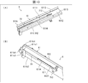
- FIG. 13A is a view showing the shape of the upper surface of the lower guide member of the guide member included in the solder supply unit shown in FIG. 1, and is a perspective view showing a state in which the mounting guide member is mounted on the lower guide member.
- 13 (B) is a view showing the shape of the lower surface of the lower guide member of the guide member, and is a perspective view showing a state in which the mounting guide member is mounted on the lower guide member.
- the production system 1 includes a component mounting device 5 and a temperature processing device 57 shown in FIGS. 12 (A) to 12 (D).
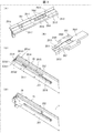
- FIG. 1 shows a solder supply provided by a solder piece manufacturing unit 12 included in a component mounting device 5 (see FIGS. 10A and 10B) configured in the production system 1 (see FIG. 11) of the present embodiment. It is a perspective view which shows the unit 2 and the solder cutting apparatus 3 (solder cutting unit 4).
- the direction in which the tape-shaped solder material 21 is sent (the tip side of the tape-shaped solder material 21) or the direction in which the solder piece cut from the tape-shaped solder material 21 is sent (the cut solder piece).
- the take-out position side will be referred to as the downstream side, and the opposite direction will be referred to as the upstream side.
- the tape-shaped solder member 21 is formed with a predetermined length, width and thickness.
- the tape-shaped solder member 21 is wound around a reel (not shown) mounted on the reel holder 23 from one end of the tape-shaped solder member 21 to the other end so as to overlap in order in the thickness direction. It is prepared and supplied in a state of being contained and housed.
- the width of the tape-shaped solder member 21 is formed in a dimension narrower than the length (for example, 50 mm or less).
- the tape-shaped solder member 21 is treated with one surface in the thickness direction as the upper surface and the other surface as the lower surface. In the present embodiment, the outer peripheral surface is treated as the lower surface while being wound on a reel.
- the tape-shaped solder member 21 is supplied by preparing a plurality of tape-shaped solder members having different width sizes and winding them on a reel having a width suitable for each size.
- a tape-shaped solder member may be prepared in a linearly stretched state without using a reel, and may be supplied as a linear body.
- solder supply unit 2 (A) is a perspective view of the solder supply unit 2 shown in FIG. 1
- FIG. 2 (B) is an enlarged view of a portion of the support member 24 in the solder supply unit 2
- FIG. 2 (C) is FIG. 2 (B).
- the solder supply unit 2 includes a base member 22, a reel holder 23, a support member 24, a guide member 25, and a holding unit 27, and is a reel holder.
- the long tape-shaped solder material 21 held by the 23 is supplied to the solder cutting device 3. Further, the solder supply unit 2 includes an identification region portion 26.
- the base member 22 is an elongated plate-shaped member extending in the feeding direction of the tape-shaped solder material 21 (hereinafter, simply referred to as a feeding direction).
- the base member 22 is supported by a moving mechanism 28 described later, and the solder supply unit 2 is placed between a mounting position S provided on the solder cutting unit 4 side and a detaching position R provided apart from the solder cutting unit 4. It is provided on the gantry 11 so as to be movable in the feeding direction (corresponding to the first direction (X direction)).
- the reel holder 23 is provided on the base member 22 (on the R side of the detachment position), and rotatably holds a reel (not shown) around which the tape-shaped solder material 21 is wound.
- the reel holder 23 includes a holder mounting portion 23a, a holder support portion 23b, and a rotation holding member 23c.
- the holder mounting portion 23a is mounted on the base member 22.
- the holder support portion 23b is provided so as to extend upward toward one end portion orthogonal to the feeding direction of the holder mounting portion 23a, and has a plate shape.
- the rotation holding member 23c is provided on the holder support portion 23b and rotatably holds the reel.
- the reel holder 23 includes a first operation portion 23d provided on one side of the holder support portion 23a and a second operation portion 23e provided on the other side of the holder support portion 23a.
- the rotation holding member 23c is configured in the holder support portion 23b including a rotation shaft RC parallel to an axis extending in the direction perpendicular to the other surface of the holder support portion 23b (width direction).
- the rotation shaft RC is arranged at the same height position as the extension portion 2512 of the guide member 25 described later.
- the first operation unit 23d and the second operation unit 23e are provided on the holder support portion 23a with the rotation holding member 23c interposed therebetween.
- the first operating portion 23d is arranged on the mounting position S side of the holder support portion 23a and above the rotation holding member 23c.
- the second operating portion 23e is located on the detachment position R side of the holder support portion 23a and is arranged below the rotation holding member 23c.
- the moving mechanism 28 includes a rail member 281 having a predetermined length in the feeding direction, a moving member 282 configured to be movable on the rail member 281, and a mounting member 283 on which the base member 22 of the supply unit 2 is mounted. To be equipped with. Further, the moving mechanism 28 is provided on the mounting position S side and is provided on the first regulating member 30 for restricting the movement of the supply unit 2 to the mounting position S side, and is provided on the detaching position R side and is provided on the detaching position of the supply unit 2. A second regulating member 29 that regulates movement to the R side is provided.
- the rail member 281 is arranged between the mounting position S and the detaching position R to guide the movement of the moving member 282.
- the moving member 282 is guided by the rail member 281 and moved between the mounting position S and the detaching position R.
- the mounting member 283 is a plate-shaped member having a predetermined length, and a mounting portion (not shown) provided on one side is mounted on the moving member 282.
- the mounting member 283 includes a defining portion 22a that defines a mounting position provided on the mounting member 283 and a mounting portion on which the base member 22 is mounted and fixed when the base member 22 is mounted on the mounting member 283. 22c and the like (see FIG. 4).
- the base member 22 is engaged with the defining portion 22a, and then the base member 22 and the mounting portion 22c are fixed. Since the position of the base portion 22 can be aligned with the specified portion 22a as a guide, the supply unit 2 can be appropriately aligned and mounted at a predetermined position.
- the mounting member 283 is mounted on the moving member 282.
- the mounting member 283 includes a first engaging member 284 that engages with the first regulating member 30, and a second engaging member 285 that engages with the second regulating member 29.
- the first engaging member 284 and the second engaging member 285 are separated from each other in the feeding direction, and are provided with the moving member 282 sandwiched between them.
- the mounting member 283 moves to the mounting position S, and the first engaging member 284 engages with the first regulating member 30, so that the supply unit 2 is positioned at the mounting position S. Further, the mounting member 283 moves to the disengagement position R, and the second engaging member 285 engages with the second regulating member 29, so that the supply unit is positioned at the disengagement position R.
- the support member 24 is provided on the base member 22 (on the mounting position S side on the base member 22) and supports the guide member 25. Specifically, the support member 24 extends in the vertical direction and supports the guide member 25 so that the guide member 25 is horizontal at a predetermined height position.
- the support member 24 includes a base mounting portion 24L to be attached to the base member 22, and a guide mounting portion 24U to which the guide member 25 is supported and mounted. Further, the guide mounting portion 24U supports the lower roller 24c so as to be rollable.
- the lower roller 24c can roll around an axis LRC parallel to the width direction of the lower roller 24c. The lower surface of the tape-shaped solder member 21 that moves guided by the guide member 25 comes into contact with the lower roller 24c.
- the support member 24 of the present embodiment two plate-shaped members are arranged at intervals in the width direction, and the first support member 24a is arranged on one side and the second support member 24b is arranged on the other side. And.
- the lower roller 24c is supported by the guide mounting portion of the first support member 24a and the guide mounting portion of the second support member 24b, and is arranged between them.
- the guide mounting portion 24U is provided with a holding mounting portion (not shown) to which the holding unit 27, which will be described later, is mounted.
- the identification area portion 26 is a portion that detects the identification portion 262 by the identification mechanism 261 described later provided on the gantry 11.
- the identification unit 262 is provided on, for example, the base member 22 of the solder supply unit 2.
- the identification unit 262 includes an identification attachment unit 262a to be attached to the base member 22, and a plurality of marking units 262b detected by the identification mechanism 261.
- the plurality of marking portions 262b are formed of a plurality of holes in the present embodiment.
- the marking portion 262b is a hole formed by arranging two marking portions 262b in the vertical direction.
- the type of the tape solder material 21 is determined by detecting these holes 262b and 262b by the detection unit 261b (in this embodiment, two detection units 261b out of the three detection units 261b).
- the identification mechanism 261 and the identification unit 262 of the identification area unit 26 may have the identification mechanism 261 configured on the base member 22 and the identification unit 262 configured on the gantry 11.
- the identification mechanism 261 is provided on the gantry 11 and includes a detection mounting portion 261a, a detection unit mounting portion 26b, and a plurality of detection units 261b.
- the detection mounting portion 261a is mounted on the first regulating member 30 that regulates the movement of the solder supply unit 2 that is moved to the mounting position S side.
- the detection unit 261b detects a plurality of marking portions 262b of the identification detection body 262.
- the detection unit 261b employs a photodetector sensor.
- the detection unit 261b is attached to the detection unit mounting portion 26b.
- the three detection units 261b are arranged and attached at predetermined intervals in the vertical direction.
- the solder supply unit 2 Since the solder supply unit 2 has the identification unit 262 of the identification area unit 26, for example, in the solder cutting device 3, the solder supply unit 2 has a reel of what kind of reel width, that is, what kind (width) of tape. It is possible to identify whether the solder material 21 is held.
- the type of tape-shaped solder material 21 set in the new solder supply unit 2 is not limited to its appearance. Difficult to distinguish.
- the type of the tape-shaped solder material 21 set on the reel can be easily identified by the identification region portion 26 included in the solder supply unit 2 itself. Therefore, even if the worker mistakenly sets the reel of the wrong tape-shaped solder material 21 in the solder supply unit 2, the mistake can be reliably detected, and a product defect due to a human error occurs. Can be prevented.
- FIG. 3 (A) is a perspective view showing the shape of the downstream portion of the upper surface of the lower guide member 251 of the guide member 25, and FIG. 3 (B) shows the shape of the upstream portion of the upper surface of the lower guide member 251 of the guide member 25.
- the perspective view shown, FIG. 3 (C) is a perspective view showing the shape of the lower surface of the lower guide member 251 and FIG. 3 (D) shows the lower surface of the lower guide member 251 mounted (engaged) on the mounting guide member 39. It is a perspective view which shows the state.
- the guide member 25 extends in the feeding direction and guides the tape-shaped solder material 21 fed from the reel.
- the guide member 25 may be configured to guide at least the lower surface of the tape-shaped solder material 21.
- the guide member 25 has a lower guide member 251 and an upper guide member 252 extending in the feeding direction. Further, the guide member 25 is provided on one end side in the feeding direction, is provided on the guide fixing portion 251a attached to the guide mounting portion 24U of the support member 24, and is provided on the other end side in the feeding direction, and is provided on the solder cutting unit 4. It is provided with a defined tip portion 251b.
- the upper guide member 252 is a plate member having a shape extending in the feeding direction so as to be overlapped with the lower guide member 251 from above the lower guide member 251.
- the upper guide member 252 has the same width as the width of the lower guide member 251 and is arranged on the upper surface of the lower guide member 251 along the feeding direction of the lower guide member 251.
- the lower guide member 251 guides the lower surface and the side surface (side portion) of the tape-shaped solder material 21. That is, in the lower guide member 251, the guide path 2511 is formed by the extension portion 2512 extending in the extension direction (predetermined direction) and the guide side wall portions 2513 and 2513 for guiding the side portions of the tape-shaped solder material 21 to be extended. Will be done. Specifically, the lower guide member 251 extends downward from one end of the upper surface of the lower guide member 251 between both ends in the direction orthogonal to the feeding direction, and is provided to face the guide side wall portions 2513, 2513. Is formed, and a guide path 2511 is formed by forming an extension portion 2512 continuous with the other ends of the guide side wall portions 2513 and 2513, respectively.
- the heights of the guide side wall portions 2513 and 2513 and the distance between the guide side walls 2513 and 2513 are set according to the width and thickness different depending on the type of the tape-shaped solder material 21, and the guide path 2511 is formed.
- the guide member 25 regulates the downward movement of the tape-shaped solder material 21 to be unwound by the extending portion 2512 of the lower guide member 251. Further, by restricting both side portions of the tape-shaped solder material 21 by the guide side wall portions 2513 and 2513, the movement of the tape-shaped solder material 21 to be fed out in the width direction is restricted. Further, the upward movement of the tape-shaped solder material 21 to be unwound is restricted by the lower surface of the upper guide member 252 arranged so as to face the extending portion 2512. As a result, the guide member 25 can stably guide the tape-shaped solder material 21 between the guide fixing portion 251a and the tip portion 251b, which are in the feeding direction.
- the tape-shaped solder material 21 to be fed out can be optimally transferred. That is, in the guide member 25, the extending portion 2512 and the guide side wall portion 2513 form a guide path 2511 for the tape-shaped solder material 21, and the lower surface of the tape-shaped solder material 21 is guided by the extending portion 2512, so that the tape-shaped solder material is used. The side portion of 21 can be guided by the guide side wall portion 2513.
- the extension portion 2512 is continuously connected to the first extension portion 2531 and the first extension portion 2531 provided with guide side wall portions 2513 and 2513 on both sides thereof. It includes a second extension portion 2532 that is provided and is not provided with guide side wall portions 2513 and 2513 on both sides thereof.
- the guide side wall portions 2513 and 2513 are provided at intervals larger than those of the first guide side wall portions 2541 and 541 and the first guide side wall portions 2541 provided at intervals so that the tape-shaped solder material 21 can be guided to each other.
- the tip portion 251b of the lower guide member 251 is attached to the solder cutting device 3 described later, the tip portion 251b is defined by the guide defining portion 338 provided in the solder cutting device 3. This is to guide the tape-shaped solder material 21 to the cutting position of the solder cutting device 3 for cutting the tape-shaped solder material 21 to be fed out.
- the lower guide member 251 is formed with inclined portions 251b1 and 251b1 at predetermined angles from the tip side in the feeding direction toward the respective side portions of the lower guide member 251 on both side portions in the width direction of the tip portion 251b. NS.
- the lower guide member 251 is set as the side tip portions 251c1,251c1 in which a certain range of both side portions in the width direction of the tip portions 251b continuous with the inclined portions 251b1 and 251b1 is defined by the guide defining portion 338. Further, in the lower guide member 251, the lower portion of the tip portion 251b is set as the lower tip portion 251b2 whose predetermined range is defined by the guide defining portion 338 from the tip side in the feeding direction.
- the guide member 25 has a lower guide portion 2514 and side guide portions 2515 and 2515 on the back surface of the lower guide member 251.
- the lower guide portion 2514 forms an upper surface portion extending in the width direction.
- the side guide portions 2515 and 2515 are provided at both ends of the lower guide portion 2514 in the width direction so as to extend upward from the back surface of the lower guide member 251.
- the side guide portions 2515 and 2515 extend in the feeding direction to the tip end portion 251b of one end of the lower guide member 251 at the position of the lower surface on one side of the guide member 25, that is, the lower guide member 251 in the width direction.
- the lower guide portions 2514 and the side guide portions 2515 and 2515 are guided to the mounting guide member 39 of the solder cutting device 3, and the solder cutting device 3 is cut.
- the tip portion 251b of the lower guide member 251 is positioned and mounted at the position. That is, the lower guide portion 2514 is provided at the tip of the extension portion 2512 in the extension direction (one side), and the extension portion 2512 is moved by the mounting guide member 39 while moving to the mounting position where the solder supply unit 2 is mounted. Downward movement is defined and guided in place.
- the side guide portions 2515 and 2515 define the lateral movement of the extension portion 2512 at a predetermined position. Guided with and positioned at the cutting position.
- the lower guide portion 2514 and the side guide portions 2515, 2515 position the tip end portion of the guide member 25 at a predetermined position of the solder cutting device 3.
- the tip portion 251b is defined by the guide defining portion 338 of the solder cutting device 3, so that the solder supply unit 2 can be efficiently and accurately mounted on the solder cutting device 3. Therefore, the tape-shaped solder material 21 fed by the guide member 25 can be accurately fed and set at the cutting position of the solder cutting device 3.
- the lower guide portion 2514, the side guide portions 2515, 2515, and the tip portion 251b are commonly provided, so that the tip portion of the guide member 25 is provided. Can be efficiently and accurately mounted at the cutting position of the solder cutting device 3.
- the extension portion 2512 of the lower guide member 251 of the guide member 25 is formed with a first opening 2516 as an opening that penetrates the extension portion 2512 in the vertical direction.
- the first opening 2516 is continuously formed and extended in the first peripheral edge portion 2551 formed in the extending direction which is the predetermined direction of the extending portion 2512 and having a predetermined length, and the first peripheral edge portion 2551. It includes a second peripheral edge portion 2552 formed with a length shorter than the width of the protruding portion 2512.
- the first opening 2516 is a second holding member of the first gripping tool (first holding member 311 and second holding member 312 shown in FIG. 6) of the solder cutting device 3 which is moved in the vertical direction. It is formed to a predetermined width so as to accept (corresponding to 312).
- the tape-shaped solder material 21 guided by the guide member 25 is arranged between the first holding member 311 and the second holding member 312 of the first gripper in the first opening 2516, and the first The holding member 311 of 1 and the second holding member 312 approach each other and come into contact with the upper surface and the lower surface of the tape-shaped solder material 21, respectively, to enable gripping.
- the first opening 2516 is formed to have a predetermined length in the feeding direction so that the second holding member 312 can move in the feeding direction.
- the first gripper can grip the tape-shaped solder material 21 in the first opening 2516 and move it in the feeding direction in the gripped state.
- a second opening 2517 is formed at a position (cutting position side) downstream of the first opening 2516 in the feeding direction.
- the second opening 2517 is a second holding member of the second gripping tool (first holding member 351 and second holding member 352 shown in FIG. 6) of the solder cutting device 3 which is moved in the vertical direction. It is formed to a predetermined width so as to accept (corresponding to 352).
- the tape-shaped solder material 21 guided by the guide member 25 is arranged between the first holding member 351 and the second holding member 352 of the second gripper in the second opening 2517, and is second.
- the holding member 351 of 1 and the second holding member 352 approach each other and come into contact with the upper surface and the lower surface of the tape-shaped solder material 21, respectively, to enable gripping.
- the second gripper can grip the tape-shaped solder material 21 through the second opening 2517 when the tape-shaped solder material 21 is cut by the solder cutting device 3, and the solder cutting device 3 can grip the tape-shaped solder material 21.
- the material 21 can be cut stably.
- the second gripping tool grips the tape-shaped solder material 21, the gripping of the tape-shaped solder material 21 by the first gripping tool is released, and the next tape-shaped solder material 21 is prepared for the feeding operation. be able to.
- the upper guide member 252 of the guide member 25 is formed with an opening 2521 having a predetermined length and width in the feeding direction with the tip portion 251b side in the feeding direction open. .. Specifically, in the opening 2521, the positions of the ends of the first opening 2516 on the guide fixing portion 251a side coincide with each other in the vertical direction in which the continuous openings from the tip portion 251b in the feeding direction toward the guide fixing portion 251a are aligned. It is formed up to the position where it is. By forming the opening 2521 in this way, an open space is formed in which the opening 2521 and the first opening 2516 and the second opening 2517 communicate with each other in the vertical direction.
- a recess 2518 (see FIG. 3C) formed at a predetermined height from the lower surface of the lower guide member 251 with a predetermined length and width in the feeding direction is formed.
- the tip portion 251b side in the feeding direction is opened, and the tip portion 251b is formed toward the guide fixing portion 251a.
- the recessed portion 2518 is formed from the tip portion 251b in the feeding direction to a position where the positions of the ends of the first opening 2516 on the guide fixing portion 251a side coincide with each other. That is, the recess 2518 is formed in the region from the front end of the first opening on the lower surface of the guide member to the tip of the guide member.
- the bottom surface of the guide path 2511 and the bottom surface of the recessed portion 2518 are second thickness dimensions that are smaller than the first thickness dimension that is the dimension between the upper surface and the lower surface of the lower guide member 251. It will be formed adjacent to each other. Thereby, the operating distance between the gripping state position and the gripping release position of the first and second gripping tools can be set as a distance larger than the second thickness dimension and smaller than the first thickness dimension. Further, in the guide member 25, since the recessed portion 2518 is formed on the lower surface within the width of the lower guide member 251 within the width direction of the guide member 25, the occupied area in the width direction can be effectively utilized.
- the holding unit 27 is provided above the guide member 25, and has a standby position when the table-shaped solder material 21 is mounted on the guide member 25 and a mounting position when the tape-shaped solder material 21 is mounted on the guide member 25. Is configured to be movable.
- the holding unit 27 urges the upper surface of the tape-shaped solder material 21 located in the guide path 2511 toward the extending portion 2512.
- the holding unit 27 includes a holding mechanism 271 that suppresses the upward movement of the tape-shaped solder material 21 guided by the guide member 25, and a holding support portion 272 that supports the holding mechanism 271.
- the holding support mechanism 271 includes a holding member (holding roller) 271b that comes into contact with the upper surface of the tape-shaped solder material 21, and a holding moving body 271a that supports and moves the holding member 271b.
- the holding member 271b is provided at the moving end portion of the holding moving body 271a, and is configured to be rotatable around a rotation axis URC set parallel to the width direction.
- the restraint support portion 272 is a mobile support mounting portion 272a that attaches the restraint movement support portion 272b that movably supports the restraint moving body 271a and the restraint movement support portion 272b to the support member 24 so as to be supportable at a position separated from the guide member 25. And.
- the holding-moving body 271a is rotatably supported by a holding-moving support portion 272a around a shaft HC extending in a direction parallel to the width direction of the tape-shaped solder material 21 unwound from the reel.
- the solder supply unit 2 can stably guide the tape-shaped solder material 21 unwound from the reel by the guide member 25 and the holding unit 27.
- solder supply unit 2 Since the guide member 25 is provided on the support member 24 and the reel holder 23 and the support member 24 are provided on the base member 22 and integrally configured, the solder supply unit 2 is attached to, for example, a solder cutting device 3. When the solder supply unit 2 is replaced, the solder supply unit 2 can be attached and detached by attaching and detaching the base member 22.
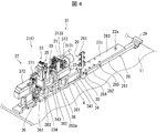
- FIG. 4 is a perspective view of the solder cutting device 3 shown in FIG.
- FIG. 5 is a front view of the solder cutting device 3 shown in FIG.
- the solder cutting device 3 includes a first holding unit 31, a first driving unit 32, a cutting unit 33, a second driving unit 34, a second holding unit 35, and a cleaning unit 36.
- a cutting solder transfer unit 37 and a frame body 38 are provided.
- the solder cutting device 3 includes a moving mechanism 28 that movably supports the solder supply unit 2 between the mounting position S and the detaching position R.
- the solder cutting device 3 includes an identification mechanism 261 for identifying the type of the tape-shaped solder material 21 to be supplied.
- the frame body 38 is provided on the gantry 11 and has a lower pedestal portion 381 and an upper pedestal portion 382.
- the lower base portion 381 is a plate-shaped member having a predetermined width and extending in the feeding direction (feeding direction) of the tape-shaped solder material 21 and having a predetermined length.
- the upper base portion 382 is a plate-shaped member located above the lower base portion 381, having substantially the same width as the lower base portion 381, and extending in the feeding direction in parallel with the lower base portion 381.
- the upper base portion 382 is a plate-shaped member having a length shorter than that of the lower base portion 381.
- the upper base portion 382 is connected to the connecting portion 383 supported by the lower base portion 381 at the downstream end portion (one end portion).
- the upper base portion 382 is connected to the auxiliary connecting portion 383a supported by the lower base portion 381 on the upstream side from the downstream end portion.
- the lower base portion 381 and the upper base portion 382 are connected to each other on one side in the first direction (X direction, feeding direction) and an auxiliary connection connected to each other on the other side in the first direction. It is connected by the portion 383a to form an integral frame body 38.
- FIG. 6 (A) is an enlarged perspective view showing the first holding portion 31 shown in FIGS. 4 and 5, and FIG. 6 (B) is an enlarged view of the second holding portion 35 shown in FIGS. 4 and 5. It is a perspective view which shows.
- the first holding unit 31 holds and releases the tape-shaped solder material 21 supplied from the solder supply unit 2.
- the first holding unit 31 includes a first holding member 311 and a second holding member 312, and a first holding driving unit 313.
- the first holding portion 31 includes a first holding member 311 and a second holding member 312, and a first holding mounting portion 31a that supports the first holding driving portion 313.
- the first holding member 311 and the second holding member 312 are provided so as to face each other and to be close to and separated from each other.
- the first holding member 311 and the second holding member 312 are provided so as to be able to approach and separate from each other in the vertical direction.
- the first holding drive unit 313 operates the first holding member 311 and the second holding member 312 in the second direction (Z direction: vertical direction) perpendicular to the flat surface portion of the tape-shaped solder material 21. ..
- the tip portions of the first holding member 311 and the second holding member 312 are formed in a plane shape so that the surfaces of the first holding member 311 and the second holding member 312 can come into contact with each other and are arranged. Further, the tip portions of the first holding member 311 and the second holding member 312 are arranged so as to be the central portion of the guide member 25 in the width direction.
- the first holding drive unit 313 applies a driving force to the third actuator 3131, the first holding member 311 and the second holding member 312, which are the driving sources of the first holding member 311 and the second holding member 312.
- a transmission mechanism 3133 for transmission is provided.
- the third actuator 3131 has a holding moving body 3132 that can move in the first direction (X direction), and has a holding operation position set in one of the first directions and a holding set in the other in the first direction.
- the holding moving body 3132 is reciprocated and linearly moved to and from the release position.
- the third actuator 3131 is supported by a support portion 31b supported by the first holding and mounting portion 31a. Further, the holding / moving body 3132 is movably supported by the supporting portion 31c supported by the first holding / mounting portion 31a.
- the holding mobile body 3132 is a member having a triangular shape in a side view, and is arranged so that the first surface 313a faces upward and the second surface 313b faces downward.
- the first surface 313a and the second surface 313b are arranged in an inclined manner so that the distance between the first surface 313a and the second surface 313b gradually decreases toward the first direction.
- the transmission mechanism 3133 converts the linear motion of the holding moving body 3132 in the first direction into a linear motion in the second direction (Z direction), and causes the first holding member 311 and the second holding member 312 in the second direction.
- the driving force to move to is transmitted.
- the transmission mechanism 3133 operates the first holding member 311 and the second holding member 312.
- the transmission mechanism 3133 includes an upper chuck mechanism portion 3134, an upper follower portion 3135, an upper elastic member (spring member) 3138, a lower chuck mechanism portion 3136, a lower follower portion 3137, and a lower elastic member (spring member) 3139. Be prepared.
- the upper chuck mechanism portion 3134 includes the first holding member 311 and the upper elastic member 3138, and the upper follower portion 3135 is connected to the first holding member 311. Further, the upper chuck mechanism portion 3134 is an upper portion (not shown) provided on the upper support body 311a so as to be movable in the vertical direction by connecting the upper support body 311a supported by the holding mounting portion 31a and the first holding member 311. Equipped with a moving body.
- One of the upper elastic members 3138 is connected to the first holding member 311 and the other is connected to the upper support 311a to apply a downward elastic force (moving force).
- the upper chuck mechanism portion 3134 is maintained in a state in which the upper follower portion 3135 is in contact with the first surface 313a of the holding moving body 3132 by the elastic force of the upper elastic member 3138, so that the first of the holding moving body 3132 is held. It enables reciprocating movement in the second direction as it moves in the direction.
- the lower chuck mechanism portion 3136 includes the second holding member 312 and the lower elastic member 3139, and the lower follower portion 3137 is connected to the second holding member 312. Further, the lower chuck mechanism portion 3136 is provided with a lower support member 312a supported by the holding mounting portion 31a and a second holding member 312 connected to the lower support member 312a so as to be movable in the vertical direction. Equipped with a moving body.
- One of the lower elastic members 3139 is connected to the second holding member 312, and the other is connected to the lower support 312a to impart an upward elastic force (moving force).
- the lower chuck mechanism portion 3136 maintains the lower follower portion 3137 in a state of being in contact with the second surface 313b of the holding moving body 3132 by the elastic force of the lower elastic member 3139, so that the first of the holding moving body 3132 It enables reciprocating movement in the second direction as it moves in the direction.
- the upper chuck mechanism portion 3134 raises the first holding member 311 from the holding position of the tape-shaped solder material 21 set in the second direction to the upper holding release position, and when it regresses, it retreats.
- the first holding member 311 is lowered from the holding release position above the tape-shaped solder material 21 set in the second direction to the holding position.
- the lower chuck mechanism portion 3136 lowers the second holding member 312 from the holding position of the tape-shaped solder material 21 set in the second direction to the lower holding release position.
- the second holding member 312 is raised from the lower holding release position of the tape-shaped solder material 21 set in the second direction to the holding position.
- the first holding portion 31 is made of a tape-shaped solder material by, for example, the second holding member 312 sucking and releasing the suction on the lower surface of the tape-shaped solder material 21 only by the lower second holding member 312.
- the configuration may be such that the holding and the holding of the 21 can be released.
- the first drive unit 32 is arranged on one side of the upper base portion 382 in the first direction, and the first holding moving body 32b on which the first holding part 31 is mounted and the first holding moving body 32b are made of a tape-shaped solder material.
- a first drive mechanism 32a for linearly feeding in the feeding direction (first direction (X direction)) of 21 is provided.
- the first holding mobile body 32b is a plate-shaped member having a predetermined width and a predetermined length in the first direction.
- the holding placing portion 31a is placed and fixed on the upper portion thereof, so that the first holding portion 31 is moved in the first direction together with the movement of the first holding moving body 32b.
- the first drive mechanism 32a includes a shaft body 32a1 whose axial center extends in the first direction, and converts the rotary motion of the built-in rotating body (not shown) into a linear motion in the first direction to convert the shaft body 32a1.
- This is an electrically driven first actuator that moves in the first direction.
- the first actuator is mounted on the upper base portion 382, includes a moving position detecting means (for example, an encoder) (not shown), sets the moving position in the first direction by numerical data, and operates by numerical control.
- the shaft body 32a1 can be moved to an arbitrary position in the first direction.
- the first driving unit 32 is configured so that the first holding moving body 32b can be reciprocated in the first direction by connecting one end of the shaft body 32a1 to the first holding moving body 32b.
- the tape-shaped solder material 21 held by the first holding unit 31 can be transferred in the feeding direction. Further, the transfer distance of the tape-shaped solder material 21 to be transferred in the feeding direction can be arbitrarily set by controlling the movement of the shaft body 32a1 of the first actuator with numerical data.
- FIG. 7A is a perspective view of the cutter unit 333 included in the cutting portion 33
- FIG. 7B is a perspective view of a state in which the support member 334 and the connecting member 3423 that support the cutter unit 333 are removed.
- 7 (C) is a perspective view in a state where the guide support member 335 is removed
- FIG. 7 (D) is a vertical sectional view of the cut portion 33 and the vicinity of the cut portion 33
- FIG. 7 (E) is a vertical cross-sectional view of the cut portion 33.
- 7 (F) is a front view
- FIG. 7 (F) is a perspective view showing the positional relationship between the cutting portion 33 and the cutting piece holding portion 371
- FIG. 7 (G) shows the positional relationship between the cutting portion 33 and the guide member 25. It is a perspective view.
- the cutting portion 33 includes a cutter unit 333, a support member 334, and a connecting member 3423.
- the connecting member 3423 is connected to the moving member 3331 described later of the cutter unit 333 and is supported by the supporting member 334 so as to be movable in the second direction.
- the support member 334 defines the position of the cutter unit 333 in the second direction. That is, the support member 334 arranges the cutter unit 333 above the upper base portion 332, and supports the cutter unit 333 to cut the tape-shaped solder material 21 at the upper position of the upper base portion 332.
- the cutting portion 33 also has a first cutting member 331 and a second cutting member 332 that are provided so as to face each other and are provided in close proximity to each other and apart from each other.
- the tape-shaped solder material 21 located at the cutting position between the cutting member 331 and the second cutting member 332 is cut.
- the first cutting member 331 is configured to be movable in a second direction (Z direction) perpendicular to the flat surface portion of the tape-shaped solder material 21. That is, the first cutting member 331 that can move up and down includes the upper blade portion 331a, and the second cutting member 332 includes the lower blade portion 332a that is provided in a fixed state at the cutting position.
- the tape-shaped solder material 21 is cut by the cutter unit 333 when the first cutting member 331 descends to the position of the broken line and the upper blade portion 331a and the lower blade portion 332a intersect.
- the width of the upper blade portion 331a and the lower blade portion 332a is formed to be larger than the width of the supplied tape-shaped solder material 21, and has a width of a plurality of sizes including the tape-shaped solder material 21 having the maximum width dimension to be supplied. It is set so that it can be commonly used for cutting the tape-shaped solder material 21.
- the width of the tape-shaped solder material 21 supplied in the present actual embodiment is set so that the maximum width is 50 mm or less and a plurality of tape-shaped solder materials 21 formed with a width smaller than the maximum width can be cut in common. NS.
- the cutter unit 333 is attached and supported by a moving member 3331 formed by the first cutting member 331 and a connecting portion 383 supported by the lower base portion 381, and is arranged on the upper portion of the support member 334 at a predetermined interval.
- a pair of guide support members 335 that guide the movement of the moving member 3331, a holding member 336 that is provided in the first direction of the moving member 3331 and regulates the movement of the moving member 3331 in the first direction, and a moving member.
- the other holding member 337 that regulates the movement of the 3331 to the other in the first direction is provided.
- the moving member 3331 has an upper mounting portion 3331a in which the first cutting member 331 is formed in the upper portion, and a lower connecting portion 3331b in the lower portion for connecting to the connecting member 3423 described later, and the upper mounting portion 3331a and the lower connecting portion 3331b.
- the opening 3332 is provided with an opening in which the tape-shaped solder material 21 can be arranged. Further, the opening of the opening 3332 allows the cutting piece holding portion 371 of the cutting solder transfer portion 37, which will be described later, to be taken in and out of the cutting support position (position adjacent to the second cutting member 332), and the cutting piece holding portion 371.
- An opening having a size that allows the moving member 3331 to move between the standby position and the cutting position when cutting the tape-shaped solder material 21 supported by the machine is formed.
- the pair of guide support members 335 are arranged in the width direction of the moving member 3331, respectively, and guide the movement in the second direction (vertical direction) while restricting the movement of the moving member 3331 in the width direction, and the guide portion 335a. It includes a cutting support portion 335b to which the second cutting member 332 is attached. Further, in the pair of guide support members 335, one holding member 336 is attached to one side in the first direction, and the other holding member 337 is attached to the other side in the first direction and above the second cutting member 332. ..
- the holding member 336 has, for example, a square frame shape, and has an opening 3371 larger than the opening 3332 at a position corresponding to the opening 3332 of the moving member 3331.
- the other holding member 337 is provided between the moving member 3331 and the portion of the regulating member 338 opposite to the first direction, and restricts the movement of the moving member 3331 to the other in the first direction.
- the regulating member 338 has a first portion 338d arranged on the upper surface of the other holding member 337 and a second portion arranged on the upstream surface of the side surface of the other holding member 337. It has 338e and.
- the second portion 338e has an opening 338c having a shape notched upward in a substantially rectangular shape from the lower end portion of the second portion 338e.
- the guide member 25 is inserted into the opening 338c, and the left and right side portions of the opening 338c serve as guide portion defining portions 338a and 338a that define the positions of the side portions of the guide member 25.
- guide lower part defining portions 338b and 338b are formed so as to project in the opposite directions of the guide portion defining portion 338a and define the position of the lower portion of the guide member 25.
- the second driving unit 34 operates the first cutting member 331 in the second direction (Z direction) perpendicular to the flat surface portion of the tape-shaped solder material 21.
- the flat surface portion is an upper surface or a lower surface of the tape-shaped solder material 21.
- the second drive unit 34 has a cutting standby position where the first cutting member 331 is provided above the upper surface of the tape-shaped solder material 21 and a cutting where the first cutting member 331 is provided below the upper surface of the tape-shaped solder material 21. Operate with the completion position.
- the second drive unit 34 is arranged on one side of the lower base portion 381 in the first direction, and includes a second moving body 34a that moves in the first direction and a second actuator 341. Further, the second drive unit 34 includes a transmission mechanism 342 that transmits the operation of the second actuator 341 to the cutting operation of the first cutting member 331.
- the second actuator 341 is mounted on the lower base portion 381 and linearly moves the transmission moving body 343 that can move in the feeding direction (first direction (X direction)).
- the transmission mechanism 342 converts the linear motion of the transmission moving body 343 into a linear motion in the second direction (Z direction) perpendicular to the flat surface portion of the tape-shaped solder material 21, and transmits the linear motion to the upper blade 331. do.
- the transmission mechanism 342 is a flat cam mechanism and includes a flat cam 3421, a cam follower 3422, and a connecting member 3423.
- the transmission moving body 343 is mounted on the moving body mounting member 343a and is driven by the second actuator 341 to move to one side in the first direction.
- the moving body mounting member 343a is provided on the mounting member support base 343b.
- the flat cam 3421 is configured on the downstream side portion of the transmission moving body 343.
- the cam surface 3421a is in a state of being inclined obliquely upward from the downstream side portion toward the upstream side portion.
- the cam follower 3422 is in contact with the cam surface 3421a of the flat cam 3421, and moves in the second direction by moving the transmission moving body 343, that is, the cam surface 3421a to one side in the first direction.
- the cam follower 3422 is supported by a connecting member 3423, which is connected to the moving member 3331 and the first cutting member 331 as described above.
- the cam follower 3422 is pushed down by the cam surface 3421a of the flat cam 3421 as the transmission moving body 343 moves to the downstream side in the first direction.
- the tape-shaped solder material 21 can be cut by the above.
- the transmission mechanism 342 of the second drive unit 34 includes an urging mechanism 3424 that urges the connecting member 3423 upward.
- the urging mechanism 3424 includes a moving end portion 3424a that is connected to the connecting member 3423 and moves with the movement of the connecting member 3423, a fixed end portion 3424b that is fixed to the lower base portion 381, and a moving end portion 3424a and a fixed end portion 3424b.
- an urging member 3424c eg, a spring member as an elastic member
- the first cutting member 331 moved downward is given an upward moving force by the urging mechanism 3424 by moving the transmission moving body 343 to the other side in the first direction by the operation of the second actuator 341.
- the upward movement is started.
- the cam follower 3422 configured on the connecting member 3423 abuts on the flat cam 3421 by the upward urging force of the urging mechanism 3424, and its upward movement is restricted.
- the restriction on the upward movement by the flat cam 3421 is gradually released.
- the first cutting member 331 is gradually moved upward by gradually releasing the restriction on the upward movement by the flat cam 3421, and the upper blade portion 331a formed of the first cutting member 331 is the first. It will be moved upward with the upward movement of the cutting member 331 of 1.
- the second holding portion 35 is provided between the first holding portion 31 and the cutting portion 33 in the first direction to hold the tape-shaped solder material 21 to be cut. And release the hold.
- the second holding unit 35 includes a first holding member 351 and a second holding member 352, and a second holding driving unit 353. Further, the second holding portion 35 is arranged above the support member 334 and the support member 35a which is connected and supported by the upper base portion 382 at a predetermined distance, and is arranged above the upper base portion 382 at a predetermined distance. And a mounting portion 35b supported by the support portion 35a. The first holding member 351 and the second holding member 352, and the second holding driving portion 353 are supported by the mounting portion 35b.
- the first holding member 351 and the second holding member 352 are provided so as to face each other and to be close to and separated from each other.
- the second holding drive unit 353 operates at least one of the first holding member 351 and the second holding member 352 in the second direction (Z direction) perpendicular to the flat surface portion of the tape-shaped solder material 21. ..
- the tip portions of the first holding member 351 and the second holding member 352 are formed in a plane shape so that the surfaces of the first holding member 351 and the second holding member 352 can come into contact with each other and are arranged. Further, the tip portions of the first holding member 351 and the second holding member 352 are arranged so as to be the central portion of the guide member 25 in the width direction.
- the second holding drive unit 353 includes a fourth actuator 3531 and a transmission mechanism 3533.
- the fourth actuator 3531 is configured in the mounting portion 35b, has an actuator operating portion 3532 that can move in the second direction (Z direction), and the actuator operating portion 3532 passes through an opening formed in the mounting portion 35b.
- the actuator operating portion 3532 is linearly moved in the vertical direction.
- the transmission mechanism 3533 operates the first and second holding members 351 and 352.
- the transmission mechanism 3533 includes an upper chuck mechanism portion 3534, an upper elastic member (spring member) 351a, an upper follower portion 3535, a lower chuck mechanism portion 3536, a lower elastic member (spring member) 352a, and a lower follower portion 3537. Be prepared.
- the transmission mechanism 3533 includes an intermediate transmission mechanism (balance mechanism) 3528 that is supported by the mounting portion 35b and transmits the linear motion of the actuator operating portion 3532 to the first holding member 351.
- the upper chuck mechanism portion 3534 includes the first holding member 351 and the upper elastic member (spring member) 351a, and the upper follower portion 3535 is connected to the first holding member 351. Further, the upper chuck mechanism portion 3534 is provided with an upper support body 351b supported by the mounting portion 35b and a first holding member 351 connected to the upper support body 351b so as to be movable in the vertical direction. It includes a body and a contact portion (not shown) included in the upper support 351b. One of the upper elastic members 351a is connected to the first holding member 351 and the other is connected to the upper support 351b to apply a downward elastic force (moving force). The upper follower portion 3535 engages with the intermediate transmission member 3538b of the intermediate transmission mechanism 3538 described later.
- the upper chuck mechanism unit 3534 rises when the actuator operating unit 3532 advances, and descends when the actuator operating unit 3532 moves backward. Specifically, in the upper chuck mechanism portion 3534, the actuator operating portion 3532 abuts on a contact portion (not shown) and is moved upward so that the first holding member 351 is moved upward and the upper follower portion 3535. Is also moved upward to abut on the engaging portion of the intermediate transmission member 3538, and when the actuator operating portion 3532 retracts, a downward elastic force (moving force) of the upper elastic member (spring member) 351a is applied. The first holding member 351 is moved downward, and the upper follower portion 3535 is also moved downward so as to be separated from the engaging portion of the intermediate transmission member 3538.
- the intermediate transmission mechanism 3538 includes an intermediate support portion 3538a supported by the mounting portion 35b and an intermediate transmission member 3538b swingably supported by the intermediate support portion 3538a. Further, the intermediate transmission mechanism 3538 includes a swing regulation mechanism 3538c that regulates the swing operation of the intermediate transmission member 3538b in one direction.
- One of the intermediate support portions 3538a is supported by the mounting portion 35b, and the intermediate transmission member 353b is swingably supported by the other end portion.
- the intermediate transmission member 3538b is a rectangular member, and is pivotally supported by the intermediate support portion 3538a so as to be swingable around a shaft whose central portion is provided parallel to the first direction.
- the intermediate transmission mechanism 3538 is configured as a balance mechanism that swingably supports the intermediate transmission member 3538b.
- the swing regulation mechanism 3538c is supported by the mounting portion 35b and regulates the upward swing movement of the other end portion of the intermediate transmission member 3538b.
- the lower chuck mechanism portion 3536 includes the second holding member 352 and the lower elastic member 352a, and the lower follower portion 3537 is connected to the second holding member 322. Further, the lower chuck mechanism portion 3536 is provided with a lower support body 352b supported by the mounting portion 35b and a second holding member 352 connected to the lower support body 352b so as to be movable in the vertical direction. Prepare with the body. One of the lower elastic members 352a is connected to the second holding member 352, and the other is connected to the lower support 352b to apply an upward elastic force (moving force).
- the lower chuck mechanism portion 3536 is maintained in a state in which the lower follower portion 3537 is moved to the other end portion of the intermediate transmission member 3538b by the elastic force of the lower elastic member 352a and is in contact with the other end portion of the intermediate transmission member 3538b. It enables reciprocating movement in the vertical direction as the part swings.
- the second holding portion 35 abuts on the abutting portion of the upper chuck mechanism portion 3534 when the actuator operating portion 3532 advances (moves) upward, and further raises the upper elastic member (spring member) 351a in the downward direction.
- the upper chuck mechanism portion 3534 is moved upward in opposition to the moving force to.
- the first holding portion 351 is moved upward and the upper follower portion 3535 is raised, and abuts on one end of the intermediate transmission member 3538b to move one end of the intermediate transmission member 3538b upward.
- the other end of the intermediate transmission member 3538b is lowered in opposition to the upward moving force of the lower elastic member (spring member) 352a, and is lowered to the other end.
- the lower follower portion 3537 that comes into contact with the lower follower portion 3537 is lowered, so that the lower chuck mechanism portion 3536 is lowered and the second holding member 352 is lowered.
- the actuator operating portion 3532 advances (moves) downward, the downward moving force of the upper elastic member (spring member) 351a is transmitted to the upper chuck mechanism portion 3534, and the upper chuck The upper chuck mechanism portion 3534 is moved downward by further moving the actuator operating portion 3532 in the direction away from the contact portion of the mechanism portion 3534. Then, the first holding portion 351 is moved downward and the upper follower portion 3535 is lowered, and the contact of one end portion of the intermediate transmission member 3538b is released, so that one end portion of the intermediate transmission member 3538b is moved upward. Is released.
- the lower chuck mechanism portion 3536 is released from moving upward at one end of the intermediate transmission member 3538b, so that an upward moving force is applied to the lower elastic member (spring member) 352a, and the second holding member 352 is moved.
- the lower follower portion 3537 As the lower follower portion 3537 is raised, the lower follower portion 3537 comes into contact with the other end portion of the intermediate transmission member 3538b, and the other end portion is raised.
- the other end of the intermediate transmission member 3538b which is moved upward by the ascending of the lower chuck mechanism portion 3536, is restricted from moving upward by the swing regulating mechanism 3538c.
- the first holding member 351 and the second holding member 352 make it possible for the first holding member 351 and the second holding member 352 to hold and release the tape-shaped solder material 21. Further, after the second holding portion 35 holds the tape-shaped solder material 21, the first holding portion 31 releases the holding of the tape-shaped solder material 21, so that the first holding portion 31 next to the tape-shaped solder material 21. You can prepare for the feeding operation. As a result, the first holding portion 31 can be efficiently prepared for the next cutting.
- the second holding portion 35 is made of a tape-shaped solder material by, for example, the second holding member 352 sucking and releasing the suction on the lower surface of the tape-shaped solder material 21 only by the lower second holding member 352.
- the configuration may be such that the holding and the holding of the 21 can be released.
- suction-holding a holding member that does not leave suction marks is adopted.
- the cleaning unit 36 is provided at a position on the downstream side of the cutting portion 33 in the frame body 38.
- the cleaning unit 36 cleans the cam surface 3421a and the cam follower 3422 of the flat cam 3421 by, for example, an air blow.
- the cleaning unit 36 has a nozzle 361 arranged toward the cam surface 3421a of the flat cam 3421 and the cam follower 3422, and blows out the supplied compressed air from the nozzle 361.
- the cleaning unit 36 may be configured to clean at least one of the cam surface 3421a of the flat cam 3421 and the cam follower 3422. As a result, at least one of the cam surface 3421a of the flat cam 3421 and the cam follower 3422 can be kept clean, and malfunction (for example, vibration) of the transmission mechanism 342 can be prevented.
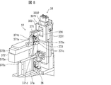
- FIG. 8 is an enlarged perspective view of the cutting solder transfer portion 37 shown in FIGS. 4 and 5.
- the cutting solder transfer unit 37 includes a cutting piece holding unit 371 and a cutting piece holding driving unit 372.
- the cut piece holding portion 371 receives and holds the solder piece cut from the tape-shaped solder material 21 by the cutting portion 33 at the cutting support position.
- the cutting piece holding drive unit 372 moves the cutting piece holding unit 371 away from the cutting support position between the taking-out position where the solder piece is taken out and the cutting support position.
- the cutting piece holding drive unit 372 is provided on the lower base portion 381, and includes a support member 37a, an actuator mounting base 372c, a fifth actuator 372a, a moving portion 372b, a holding portion support portion 372c, and a support portion 371a.
- the support member 37a is provided on the lower base portion 381 to support the actuator mounting base 372c, and the actuator mounting base 372c is on which the fifth actuator 372a is mounted.
- the fifth actuator 372a reciprocates the moving portion 372b in the first direction.
- the support portion 371a is provided in the regulation portion 371c and supports the moving body 371b, that is, the cut piece holding portion 371 while enabling the movement in the vertical direction. As a result, the cutting piece holding portion 371 can be reciprocated between the take-out position and the cutting support position in the first direction by being driven by the fifth actuator 372a.
- the cutting piece holding drive unit 372 includes a height adjusting unit 373a that adjusts the height position of the cutting piece holding unit 371.
- the height adjusting portion 373a includes an elastic member 371d that applies an upward moving force of the moving body 371b, and a height adjusting screw 373 that regulates the upward movement of the moving body 371b and adjusts the height.
- the elastic member 371d is arranged between the moving body 371b and the regulating portion 371c.
- the height adjusting screw 373 is fixed to the regulating portion 371c, and the height position that supports the lower surface of the tape-shaped solder material 21 at the cutting position by adjusting the movement of the cutting piece holding drive portion 372 upward by the screw mechanism. To adjust.
- the cutting piece holding portion 371 is provided so as to pass through the opening 3332 in the support member 3331 of the cutter unit 333, and is set in the cutter unit 333. Adjacent to the second cutting member 332 at the cutting position. Further, the cutting piece holding portion 371 has a height adjusting mechanism (screw mechanism) 373a so as to be at the same height position as the supporting surface of the second cutting member 332 that supports the lower surface of the tape-shaped solder material 21 before cutting. Adjusts the height of the support surface that supports the tape-shaped solder material 21. As a result, the cutting solder transfer unit 37 can transfer the solder piece from the cutting support position to the take-out position by the cutting piece holding unit 371.
- a height adjusting mechanism screw mechanism
- solder cutting device 3 sets the axial direction of the drive shaft and the advancing / retreating direction of the drive unit in the first direction, not in the width direction of the tape-shaped solder material 21, in other words, in the first direction and orthogonal to the second direction. Alternatively, it is configured toward the second direction. That is, in the solder cutting device 3, the axis of the drive shaft does not face the width direction of the tape-shaped solder material 21, and the drive unit does not advance or retreat in the width direction of the tape-shaped solder material 21. Therefore, the solder cutting device 3 can significantly reduce the device size (dimensions) of the tape-shaped solder material 21 in the width direction as compared with the conventional device described in Patent Document 1 and the like.
- the device width of the conventional device is 200 mm
- the device width of the solder cutting device 3 at the same scale is 50 mm or less
- the device width is actually 1/4 or less.
- the first drive unit 32 which is the first actuator
- the second drive unit 34 having the holding mobile body 3132, the second actuator 341 and the transmission mechanism 342. Since the device width per unit of the solder cutting device 3 is significantly small, for example, a plurality of solder cutting devices 3 are installed side by side in the width direction, and the solder pieces supplied from each solder cutting device 3 are installed. In the system to be used, the effect of suppressing the width of the solder cutting device 3 is increased in proportion to the number of the solder cutting devices 3 installed. As a result, the footprint of this system is reduced, so that the system can be miniaturized.
- soldering cutting unit 4 As shown in FIGS. 4 and 5, the solder cutting unit 4 includes a frame body 38, and the frame body 38 includes a first holding unit 31, a first driving unit 32, a cutting unit 33, and a third in the solder cutting device 3.
- the configuration is such that the drive unit 34 and the second holding unit 35 of 2 are mounted.
- the frame body 38 includes a first support portion 38a in which the first drive portion 32 is provided, a cutting support portion 38b in which the cutting portion 33 is provided, and a second support portion 38c in which the second drive portion 34 is provided.
- a second holding support portion 38d provided with the second holding portion 35 is provided.
- the first holding unit 31 is mounted on the first driving unit 32.
- first layer portion which is the lowermost layer of the frame body 38, that is, the lower base portion 381 and the upper base portion 382
- a second actuator 341, and a flat cam 3421, a cam follower 3422, and a connecting member 3423 of the transmission mechanism 342 are located below. Is provided. Specifically, the tape-shaped solder material 21 is guided by the guide member 25 arranged above the first layer portion, is fed above the first layer portion, and is fed in this way.
- a first holding portion 31, a first driving portion 32, a cutting portion 33, and a second driving portion 34 are provided between the first layer portion and the first holding portion 31, and a first driving portion 32.
- first holding member 311 of the first holding portion 31 and the first holding member 351 of the second holding portion 35 are located above the tape-shaped solder material 21.
- the upper blade (first cutting member) 331 of the cutting portion 33 is located above the tape-shaped solder material 21.
- the entire device of the plurality of solder cutting devices 3 is provided. Since the width is small, the movable width (moving distance) of the transfer unit 54 can be small. This means that the work time required for transferring the solder pieces in the component mounting device 5 is shortened. That is, in the component mounting device 5, the solder pieces can be transferred in a short cycle time, and high-speed processing is possible. Further, since the solder cutting unit 4 can be replaced together with the frame body 38, the replacement work is easy and the positioning reproducibility at the time of re-installation is also good.
- the solder cutting unit 4 is provided with a second actuator 341 and a transmission mechanism 342 on the lower base portion 381 in the first layer portion, and is arranged above the first layer portion. Guided by the guide member 25, the tape-shaped solder material 21 is sent above the first layer portion.
- the upper base portion 382 is provided between the tape-shaped solder material 21 to be fed and the first layer portion, and the upper base portion 382 is provided with a first drive portion 32 (first actuator) and a second holding portion 35. Be done.
- the upper base portion 382 and the lower base portion 381 of the frame body 38 include a connecting portion 383 that is connected to each other on one side in the feeding direction (first direction).
- the first drive unit 32 (first actuator) is provided on the other side of the upper base portion 382, which is separated from the connecting portion 383, and the second actuator 341 is located on the other side of the lower base portion 381, which is separated from the connecting portion 383. It is provided.
- the first drive unit 32 (first actuator) and the second drive unit 34 (second actuator 341) from one of the plurality of solder cutting units 4 arranged side by side are particularly separated from the frame body 38. Easy to remove when removing. At the time of this removal work, the solder supply unit 2 is removed from the solder cutting unit 4 prior to the removal of the first drive unit 32 and the second drive unit 34.
- the solder cutting unit 4 includes a first holding unit 31, a first driving unit 32, a cutting unit 33, a second driving unit 34, a second holding unit 35, and a cutting solder transfer unit 37.
- the frame body 38 is provided with a solder transfer support portion in which the cutting solder transfer portion 37 is provided.
- the first holding portion 31, the first driving portion 32, the cutting portion 33, the second driving portion 34, and the second holding portion 35 are on the supply processing side to which the tape-shaped solder material 21 is supplied based on the connecting portion 383.
- the cut solder transfer portion 37 is provided on the take-out side from which the solder pieces cut based on the connecting portion 383 are taken out.
- solder cutting unit 4 can be replaced together with the frame body 38 including the cutting solder transfer unit 37, so that the replacement work is easy.
- the solder supply unit 2 is removed from the solder cutting unit 4 prior to the replacement of the solder cutting unit 4.
- FIG. 9 is an explanatory diagram of the operation of the solder cutting device 3 shown in FIG. 5 from feeding the tape-shaped solder material 21 by the first holding portion 31 to cutting the tape-shaped solder material 21 by the cutting portion 33.
- FIG. 10 shows the operation steps up to cutting divided into eight "(1) to (8)" in order, and the reference numerals corresponding to each step are represented by (1) to (8).
- the solder cutting device 3 cuts the tape-shaped solder material 21 into solder pieces 211 having a predetermined length through the steps from the state ST91 to the state ST98.
- the state ST91 is a state in which the first and second holding members 311, 312 are opened
- the state ST92 is a state in which the tape-shaped solder material 21 is fed
- the state ST93 is a state in which the first and second holding members 311, 312 are closed and the tape is taped.
- the state ST94 is a state in which the first and second holding members 311, 312 are opened
- the state ST95 is a state in which the first holding portion 31 is retracted together with the unit
- the state ST96 is a state in which the first and second holding members 31 and 312 are sandwiched.
- the second holding members 311, 312 are closed and the tape-shaped solder material 21 is sandwiched again
- the state ST97 is a state in which the first holding portion 31 is advanced together with the unit
- the state ST98 is taped by the upper blade 331 and the lower blade 332.
- the state in which the tip portion of the solder material 21 is cut and the solder piece 211 is cut out is shown.
- the process returns to the state ST94 in order to cut out a new solder piece 211 from the tape-shaped solder material 21, and the steps from the state ST94 to the state ST98 are sequentially repeated.
- solder piece manufacturing apparatus 12 As shown in FIG. 1, the solder piece manufacturing apparatus 12 includes a solder cutting unit 4 and a solder supply unit 2. That is, the solder piece manufacturing apparatus 12 is attached to the gantry 11 and the gantry 11, and is continuous with the solder cutting unit 4 and the solder cutting unit 4 which are attached to the gantry 11 and cut the continuous tape-shaped solder material 21 to a predetermined length to form a solder piece. A solder supply unit 2 for supplying the tape-shaped solder material 21 is provided. As a result, in the solder piece manufacturing apparatus 12, when the solder piece is manufactured, the tape-shaped solder material 21 can be easily replaced or a new supply can be easily performed, so that the solder piece can be manufactured efficiently. be.
- the solder cutting unit 4 is provided with an identification mechanism (identification member) 261 that identifies the reel width of the reel by detecting the marking portion 262b.
- an identification mechanism identification member
- the solder cutting unit 4 is replaced in the solder piece manufacturing apparatus 12, even if the base member 22 of the solder cutting unit 4 is attached and detached, the solder cutting unit 4 still has the identification mechanism (identification member) 261.
- the reel width of the reel can be identified by detecting the marking portion 262b.
- the solder cutting unit 4 identifies the reel width of the reel by detecting the marking portion 262b (identification member). ) 261 is provided.
- the frame body 38 is provided on the gantry 11, the base member 22 is supported by the moving mechanism 28, and the solder supply unit 2 is placed in the first direction between the mounting position S and the attachment / detachment position R. It is provided on the gantry 11 so as to be movable.
- An identification area portion 26 is provided on the gantry 11.
- the reel holder 23 and the support member 24 are provided on the base member 22, and the guide member 25 is provided on the support member 24 and is integrally formed. Therefore, in the solder piece manufacturing apparatus 12, when the solder supply unit 2 is replaced, the solder supply unit 2 can be efficiently attached and detached by attaching and detaching the base member 22 of the solder supply unit 2.
- solder cutting unit 4 can be shared and is configured in common, so that a plurality of solder piece manufacturing devices 12 can be efficiently used. It is possible to efficiently replace the solder supply unit 2 according to the type of the above.
- Parts mounting device 5) 10 (A) is a cross-sectional perspective view showing a state in which the component mounting device 5 is cut along the first direction (feeding direction), and FIG. 10 (B) is an arrow indicating the component mounting device 5 of FIG. 10 (A). It is a perspective view when viewed from the direction of 10B.
- the component mounting device 5 is a so-called mounter, and includes a stand 11, a solder cutting unit group 51, a mounting support portion 52, and a transfer unit 54. Further, the component mounting device 5 includes an imaging unit 58. Further, the component mounting device 5 includes a first transport device 53.
- the gantry 11 includes a leg portion 11a, a mounting portion 11b, a support portion 11c, and a base portion 11d.
- the base 11d is a flat plate base-like member located below the base 11.
- the leg portion 11a is a plurality of columnar members provided on the base 11d and supports the mounting portion 11b.
- the mounting portion 11b is a flat plate base-like member on which the solder supply unit 2 and the solder cutting unit 4 are mounted.
- the support portion 11c is provided at the left and right positions of the solder supply unit 2 and the solder cutting unit 4 in the width direction of the mounting portion 11b, and supports the transfer unit 54.
- the solder supply unit 2 and the solder cutting device 3 (solder cutting unit 4) included in the solder piece manufacturing unit 12 are mounted on the gantry 11 (mounting).
- a plurality of portions 11b) are arranged side by side in the width direction. More specifically, a flat plate-shaped mounting receiving member 51a is provided on the gantry 11 (mounting portion 11b), and the solder piece manufacturing apparatus 12 is provided on the mounting receiving member 51a.
- the solder cutting unit group 51 has a configuration in which a plurality of solder cutting units 4 are detachably arranged in parallel on a gantry 11.
- the first solder cutting unit group 511 is arranged on one side in the width direction
- the second solder cutting unit group 512 is arranged on the other side in the width direction.
- the first solder cutting unit group 511 a plurality of types of tape-shaped solder materials 21 are supplied, and solder pieces required for the mounting object 56 are manufactured.
- the second solder cutting unit group 512 is also supplied with the same type of tape-shaped solder material 21 as the first solder cutting unit group 511, and manufactures the solder pieces required for the mounting object 56.
- the first solder cutting unit group 511 and the second solder cutting unit group 512 By manufacturing the same type of solder pieces in the first solder cutting unit group 511 and the second solder cutting unit group 512, even if the manufacturing of the solder pieces in the first solder cutting unit group 511 is interrupted, the first It becomes possible to manufacture the same type of solder pieces by backing up with the solder cutting unit group 512 of No. 2, and the solder pieces can be continuously mounted on the mounting object 56 in the component mounting device 5 without stopping. Can be done.
- the mounting support portion 52 is provided on the gantry 11 and supports the mounting object 56 (see FIG. 11), which is a work on which the solder piece 211 cut from the tape-shaped solder material 21 is mounted.
- the mounting object 56 may be a tray accommodating a plurality of solder pieces 211.
- the mounting support portion 52 is indicated by a dotted ellipse.
- the mounting support portion 52 corresponds to, for example, a positioning unit configured in the middle of the conveyor (including one that engages with a positioning pin configured on a mounting table).
- the first transfer device 53 is provided on the gantry 11 and conveys the mounting object 56 before the solder piece 211 is mounted to the mounting support portion 52, and also supports the mounting after the solder piece 211 is mounted.
- the mounting object 56 of the portion 52 is conveyed to the outside of the mounting support portion 52.
- a conveyor including an endless moving member for example, a chain or a belt
- a conveyor in which a plurality of rollers are arranged, a moving unit that holds and moves the mounting object 56, and the like are adopted. .. More specifically, a flat plate-shaped mounting receiving member 53a is provided on the gantry 11 (mounting portion 11b), and a first transport device 53 is provided on the mounting receiving member 53a.
- the transfer unit 54 transfers and mounts each solder piece 211 cut by the solder cutting unit group 51 onto the mounting object 56 of the mounting support portion 52.
- the transfer unit 54 has a transfer head unit 541 and a head support portion 542.
- the head support portion 542 supports the transfer head unit 541 and is erected on two support portions 11c and 11c provided apart from each other, and can move in the X direction (feeding direction (first direction)).
- the transfer head unit 541 can move in the third direction, which is the Y direction orthogonal to the X direction.
- a plurality of transfer head units 541 hold solder pieces 211 (see FIG.
- the transfer head unit 54 can move in a second direction (vertical direction) which is the Z direction orthogonal to the X direction and the Y direction (in this embodiment, the transfer head unit 541). It has two) holding units 5411. As a result, the transfer unit 54 holds the solder piece 211 on the cut piece holding portion 371, and transfers the solder piece 211 to the mounting object 56 of the mounting support portion 52.
- the image pickup unit 58 is provided between the solder cutting device 3 and the mounting support portion 52, and images the solder piece held by the transfer head unit 541 of the transfer unit 54 from below, and obtains a predetermined reference position and reference posture.
- the correction value that becomes the position error in the XY direction and the attitude error around the axis in the Z direction is calculated.
- the imaging unit 58 includes an imaging unit including a camera and a light source unit that serves as a light source for imaging.
- the component mounting device 5 configured in this way reduces the occupied area of the component mounting device 5 in the width direction by adopting the solder piece manufacturing device 12 including the solder cutting unit 4 and the solder supply unit 2 of the present invention. It is possible to make effective use of the installation location. Further, since the moving distance by the transfer unit 54 is shortened, the solder pieces can be mounted efficiently. Further, since the component mounting device 5 can easily replace the tape-shaped solder material 21, the solder piece 211 can be continuously and efficiently mounted on the mounting object 56.
- FIG. 1 11 (A) to 11 (E) are schematic views showing each type of component mounting device 5.
- the mounting support portion 52 is provided inside the region of the component mounting device 5, and the mounting object 56 is positioned and supported inside the region of the component mounting device 5.
- the transfer of the mounting object 56 to the mounting support 52 inside the region of the component mounting device 5 or the transfer of the mounting object 56 from the mounting support 52 of the region of the component mounting device 5 is a transfer device (not shown). Performed by the worker.
- the component mounting device 5 of the type T1 is a type in which the first transport device 53 is configured on the component mounting device 5 of the reference type T0.
- the first transfer device 53 is provided inside the region of the component mounting device 5, and the mounting object 56 is transferred inside the region of the component mounting device 5.
- a mounting support portion 52 is provided in the middle thereof, and the mounting object 56 is transferred to the mounting support portion 52 and also transferred from the mounting support portion 52. Further, the first transfer device 53 receives and transfers the mounting object 56 from the outside of the area of the component mounting device 5, and transfers and transfers the object to be mounted to the outside of the area of the component mounting device 5.
- the type 2 component mounting device 5 is a type in which the first transport device 53 is configured on the reference type T0 component mounting device 5.
- the type T2 component mounting device 5 is provided so that the first transport device 53 passes through the region of the component mounting device 5, and the mounting object 56 is placed between the inside of the region and the outside of the region of the component mounting device 5. Transfer.
- a mounting support portion 52 is provided in the middle thereof, and the mounting object 56 is transferred to the mounting support portion 52 and also transferred from the mounting support portion 52. Further, the first transfer device 53 receives and transfers the mounting object 56 from the outside of the area of the component mounting device 5, and transfers and transfers the object to be mounted to the outside of the area of the component mounting device 5.
- the type 3 component mounting device 5 is a type in which the first transport device 53 is configured on the reference type component mounting device 5.
- the component mounting device 5 of type T3 is provided so that the first transfer device 53 passes through the region of the component mounting device 5, and the mounting object 56 is placed between the inside of the region and the outside of the region of the component mounting device 5.
- the mounting support portion 52 is provided inside the region of the component mounting device 5 in the direction intersecting the transfer direction of the first transport device 53, and the mounting target 56 is combined with the mounting support 52 by a mounting target transfer mechanism (not shown). It is transferred to and from the first transfer device 53. Further, the first transfer device 53 receives and transfers the mounting object 56 from the outside of the area of the component mounting device 5, and transfers and transfers the object to be mounted to the outside of the area of the component mounting device 5.
- the second transfer device 55 described later is arranged outside the region of the component mounting device 5 and adjacent to the component mounting device 5. It may be configured (type T3-1).
- the component mounting device 5 of type T3-1 is a type in which a second transfer device 55 is added to the component mounting device 5 of reference type T0.
- the component mounting device 5 of type T3-1 is provided so that the second transport device 55 transports the mounting object 56 along the inside of the region while the second transport device 55 is adjacent to the inside of the region of the component mounting device 5.
- the mounting support portion 52 is provided inside the region of the component mounting device 5 in the direction intersecting the transfer direction of the second transport device 55, and the mounting target 56 is combined with the mounting support 52 by a mounting target transfer mechanism (not shown). It is transferred to and from the second transfer device 55.
- FIGS. 12 (A) to 12 (D) are schematic views showing a production system 1 provided with the component mounting devices 5 of each type shown in FIGS. 11 (A) to 11 (E). Further, the production system 1 includes a temperature processing device 57 that performs temperature processing of the mounting object 56 on which the solder piece 211 is mounted.
- the determination piece manufacturing apparatus 12 including the solder supply unit 2 and the solder cutting apparatus 3 (solder cutting unit 4) and the transfer unit 54 are omitted.
- the production system 1 shown in FIG. 12A includes a type T1 component mounting device 5 and a temperature processing device 57. Further, the production system 1 includes a plurality of component mounting devices 5, and transports the mounting object 56 between the component mounting devices 5, transports the mounting object 56 inside the region of the component mounting device 5, and the component mounting device 5.
- the second transport device (mounting target transfer device) 55 that transports the mountable object 56 to the temperature processing device 57 and the mountable object 56 to the production system 1 is included.
- the component mounting device 5 of type T1 is arranged so that the transport path of the mounting object 56 is formed continuously (in a straight line in FIG. 12A).
- a transport path is formed by connecting the first transport device 53 configured in the component mounting device 5 of type T1 and the second transport device 55 for transport.
- the component mounting device 5 arranged in the broken line portion of the production system 1 may be either the component mounting device 5 of the reference type T0 or the component mounting device 5 of the type T1.
- the component mounting device 5 arranged in the broken line portion includes the component mounting device 5 of type T1 and is part of the preconfigured second transfer device 55.
- the component mounting device 5 of the reference type T0 may be configured.
- the production system 1 shown in FIG. 12B includes a type T2 component mounting device 5 and a temperature processing device 57.
- the production system 1 includes a plurality of component mounting devices 5, and transports the mounting object 56 between the component mounting devices 5, transports the mounting object 56 inside the region of the component mounting device 5, and the component mounting device 5.
- the object 56 to be mounted on the temperature processing device 57 is transported by the first transport device 53 included in the component mounting device 5 of the type T2.
- the type T2 component mounting device 5 is arranged so that the transport path of the mounting object 56 is continuously formed (in a straight line in FIG. 12B), and the respective component mounting devices 5 are arranged.
- a transport path is formed by connecting the first transport devices 53 configured in the device 5 to each other.
- the production system 1 shown in FIG. 12C includes a type T3 component mounting device 5 and a temperature processing device 57.
- the production system 1 includes a plurality of component mounting devices 5, and transports the mounting object 56 between the component mounting devices 5 by a first transport device 53 configured in each component mounting device 5. Further, the production system 1 includes a temperature processing device 57 and a second transfer device 55 that transfers the object to be mounted 56 to the production system 1.
- the component mounting device 5 of type T3 is arranged so that the transport path of the mounting object 56 is continuously formed (linearly in FIG. 12C), and the component mounting device 5 is arranged.
- a transport path is formed by connecting the first transport device 53 configured with the above and the second transport device 55.
- the production system 1 shown in FIG. 12D includes a component mounting device 5 of reference type T0 and a temperature processing device 57.
- the production system 1 is provided with a plurality of component mounting devices 5, and a second transport device 55 that transports the mounting object 56 to and from each component mounting device 5 and the mounting object 56 to the temperature processing device 57.
- a second transport device 55 is provided so that the transport path of the object to be mounted 56 is continuously formed (linearly in FIG. 12D), and the second transport device 1 is provided.
- the component mounting device 5 and the temperature processing device 57 are arranged along the transport path on one side of the 55.
- the component mounting device 5 and the temperature processing device 57 are arranged side by side along the transport path of the second transport device 55, the component mounting device 5 and the temperature are arranged according to the production capacity of the production system 1.
- the processing device 57 can be easily increased or decreased.
- the production system 1 can be constructed by the component mounting device 5, the temperature processing device 57, and the second transfer device 55. In this configuration, when the solder supply unit 2 attached to the solder cutting device 3 is replaced, the solder supply unit 2 can be attached and detached by attaching and detaching the base member 22. As a result, the operating efficiency of the entire production system 1 is improved.
- the production system 1 includes a solder supply unit 6 instead of the solder supply unit 2, and a solder cutting device 7 instead of the solder cutting device 3.
- the configuration of the other production system 1 is the same as that of the first embodiment.
- FIG. 13A is a diagram showing the shape of the upper surface of the lower guide member 611 of the guide member 61 included in the solder supply unit 6 of the present embodiment, showing a state in which the mounting guide member 73 is mounted on the lower guide member 251.
- FIG. 13B is a perspective view showing the shape of the lower surface of the lower guide member 611 of the guide member 61, and is a perspective view showing a state in which the mounting guide member 73 is mounted on the lower guide member 251.
- the solder supply unit 6 includes a guide member 61 instead of the guide member 25 of the solder supply unit 2.
- Other configurations of the solder supply unit 6 are the same as those of the solder supply unit 2.
- the guide member 61 has a lower guide member 611 and an upper guide member 612 extending in the feeding direction.
- the lower guide member 611 and the upper guide member 612 have a configuration corresponding to the lower guide member 251 and the upper guide member 252 of the solder supply unit 2.
- the lower guide member 611 has a guide path 6111, an extension portion 6112, and a guide side wall portion 6113 on the upper surface.
- the guide path 6111 corresponds to the guide path 2511 of the lower guide member 251;
- the extension portion 6112 corresponds to the extension portion 2512 of the lower guide member 251 and the guide side wall portion 6113 corresponds to the guide side wall portion 2513 of the lower guide member 251.
- the upper guide member 612 has the same shape as the upper guide member 252 of the solder supply unit 2 and has an opening 6121 corresponding to the opening 2521.
- An opening 6114 is formed in the lower guide member 611 of the guide member 61.
- the opening 6114 extends in the upstream direction from the downstream end of the lower guide member 611.
- the upstream end of the opening 6114 is at the same position as the upstream end of the first opening 2516 of the lower guide member 251.
- the opening 6114 is capable of accepting the first and second grips of the solder cutting device 7, which are inserted from below. Further, the forming range of the opening 6114 coincides with, for example, the forming range of the opening 6121 of the upper guide member 612.
- the lower guide member 611 has a tip portion 611b, two inclined portions 611b1, 611b1, two lower tip portions 611b2, 611b2, and two side tip portions 611c1, 611c1.
- the tip portion 611b corresponds to the tip portion 251b of the lower guide member 251
- the inclined portion 611b1 corresponds to the inclined portion 251b1 of the lower guide member 251
- the lower tip portion 611b2 corresponds to the lower tip portion 251b2 of the lower guide member 251.
- the side tip portion 611c1 corresponds to the side tip portion 251c1 of the lower guide member 251.
- the functions of the respective parts of the guide member 61 are the same as the functions of the corresponding parts of the guide member 25.
- the mounting guide member 73 of the solder cutting device 7 is inserted into the opening 6114 from the tip portion 611b, and the lower guide member 611 is inserted until it reaches the mounting position. Guide.
- the tip portion 611b of the guide member 61 is guided by the guide defining portion 338 to be mounted at a predetermined position, and the upper surface of the mounting guide member 73 is mounted.
- the surface of the extension portion 6112 can be set at the same height position. Therefore, the tape-shaped solder material 21 fed by the guide member 61 can be accurately fed and set at the cutting position of the solder cutting device 7.
- the solder supply unit 6 has the same advantages as the solder supply unit 2.
- FIG. 14 is a perspective view of the solder cutting device 7.
- FIG. 15 is a front view of the solder cutting device 7.
- the solder cutting device 7 includes a first holding portion 71 in place of the first holding portion 31 of the solder cutting device 3, and a second holding portion 72 in place of the second holding portion 35. To be equipped.
- Other configurations of the solder cutting device 7 are the same as those of the solder cutting device 3.
- FIG. 16 (A) is a side view of the first holding portion 71 and the second holding portion 72 shown in FIGS. 14 and 15, and FIG. 16 (B) is a partially enlarged view of the first holding portion 71 and the second holding portion 72. It is a perspective view.
- the first holding portion 71 is the same as the first holding portion 31 of the first embodiment, in the second embodiment, the first and second holding members 711, 712 and a first holding drive unit 713 are provided to hold and release the tape-shaped solder material 21.
- the first holding member 711 is a moving member that can move in the vertical direction
- the second holding member 712 is a fixed fixed member that does not move in the vertical direction. Therefore, the holding drive unit 713 operates only the first holding member 711 in the second direction (Z direction) perpendicular to the flat surface portion of the tape-shaped solder material 21.
- the holding drive unit 713 corresponds to the third actuator 7131 corresponding to the third actuator 3131 of the first holding drive unit 313 of the first embodiment and the transmission mechanism 3133 of the first holding drive unit 313 of the first embodiment.
- the transmission mechanism 7133 and the holding mobile body 7132 corresponding to the holding moving body 3132 of the first embodiment are provided.
- the transmission mechanism 7133 converts the linear motion of the holding moving body 7132 in the first direction (X direction) into a linear motion in the second direction (Z direction), and converts the linear motion of the first holding member 711 in the second direction (Z direction). ) Is transmitted as a linear motion.
- the transmission mechanism 7133 includes an upper chuck mechanism portion 7134 corresponding to the upper chuck mechanism portion 3134 of the first embodiment, an upper follower portion 7135 corresponding to the upper follower portion 3135 of the first embodiment, and a spring of the first embodiment.
- a spring 7138 corresponding to 3138 is provided.
- the operation of the transmission mechanism 7133 that operates the upper chuck mechanism unit 7134 is the same as that of the transmission mechanism 3133 of the first embodiment.
- the first holding portion 71 may have various configurations depending on the application or combination of conventionally known techniques, but the tape-shaped solder material 21 is held and released. However, the configuration disclosed above is not particularly limited.
- the second holding portion 72 includes a first holding member 721 corresponding to the first holding member 351 of the second holding portion 35 of the first embodiment, and A second holding drive unit 723 corresponding to the second holding drive unit 353 of the first embodiment is provided, and the tape-shaped solder material 21 is held and released.
- the mounting guide member 73 functions as a second holding member (second gripping tool) instead of the second holding member 352 of the second holding portion 35 of the first embodiment.
- the mounting guide member 73 is provided in the cutting portion 33 and extends in a direction opposite to the feeding direction.
- the second holding drive unit 723 operates the first holding member 721 in the second direction (Z direction) perpendicular to the flat surface portion of the tape-shaped solder material 21.
- the second holding drive unit 723 is a transmission mechanism of the fourth actuator 7231 corresponding to the fourth actuator 3531 of the second holding drive unit 353 of the first embodiment and the second holding drive unit 353 of the first embodiment.
- a transmission mechanism 7233 corresponding to 3533 is provided.
- the transmission mechanism 7233 includes an upper chuck mechanism portion 7234 corresponding to the upper chuck mechanism portion 3534 of the transmission mechanism 3533 of the first embodiment.
- the upper chuck mechanism portion 7234 includes a first holding member 721 and a spring 7235. The spring 7235 urges the first holding member 721 downward.
- the fourth actuator 7231 When the fourth actuator 7231 operates, the upper chuck mechanism portion 7234 rises with the upward movement of the moving body (not shown) of the fourth actuator 7231, the fourth actuator 7231 stops its operation, and the fourth actuator When the moving body (not shown) of the 7231 moves downward, it is urged by the spring 7235 and descends together with the moving body (not shown) of the fourth actuator 7231.
- the first holding member 721 moves the tape-shaped solder material 21 downward by lowering, and holds the tape-shaped solder material 21 in the guide member 61 together with the mounting guide member 73 by pressing the tape-shaped solder material 21 against the mounting guide member 73. ..
- the first holding member 721 and the mounting guide member 73 make it possible for the first holding member 721 and the mounting guide member 73 to hold and release the tape-shaped solder material 21.
- Other operations of the second holding unit 72 are the same as the operations of the second holding unit 35 of the first embodiment. Similar to the second holding portion 35 of the first embodiment, the second holding portion 72 may have various configurations depending on the application or combination of conventionally known techniques, but the tape-shaped solder material 21 is held and released. However, the configuration disclosed above is not particularly limited.
- solder cutting device 7 has a configuration in which only the first holding member 711 is raised and lowered by the first holding portion 71, and only the first holding member 721 is raised and lowered by the second holding portion 72. Thereby, it is possible to simplify the configuration of the holding drive unit 713 of the first holding unit 71 and the second holding driving unit 723 of the second holding unit 72.
- the solder supply unit 6 is attached to the solder cutting device 7, as shown in FIGS. 13 (A) and 13 (B), the first is opened in the opening 6114 of the lower guide member 611 of the guide member 61.
- the second holding member 712 of the holding portion 71 and the mounting guide member 73 are inserted, and these function as guides on the lower surface of the tape-shaped solder material 21.
- the tape-shaped solder material 21 can be stably guided.
- Other advantages of the solder cutting device 7 are the same as those of the solder cutting device 3 of the first embodiment.
- the first holding portion for holding and releasing the long tape-shaped solder material and the first holding portion are mounted and held by the first holding portion. It has first and second cutting members that are provided so as to face each other and are provided in close proximity to and separately from the first driving unit that linearly feeds the tape-shaped solder material in the first direction, and the first and second cutting members are provided.
- the cutting portion for cutting the tape-shaped solder material located at the cutting position between the cutting members and at least one of the first and second cutting members are perpendicular to the flat surface portion of the tape-shaped solder material.
- the first drive unit includes a second drive unit that operates in the second direction, and the first drive unit converts a rotary motion of a rotating body whose axis extends in the first direction into a linear motion in the first direction.
- This is an electrically driven first actuator
- the second driving unit is a second actuator that linearly moves a moving body that can move in the first direction, and a second actuator that linearly moves the moving body in the second direction. It is provided with a transmission mechanism that converts it into a linear motion to and transmits it to at least one of the first and second cutting members.
- the solder cutting device has no drive shaft or drive unit that moves in the direction orthogonal to the first direction and the second direction, and is in the direction orthogonal to the first direction and the second direction. It is possible to narrow the width.
- the first drive unit which is the first actuator
- the second drive unit which has a moving body, a second actuator, and a transmission mechanism.
Abstract
半田切断装置(3)は、第1保持部(31)と、第1保持部(31)が保持するテープ状半田材(21)を第1方向に送る第1の駆動部(32)と、テープ状半田材(21)の切断部(33)と、切断部(33)を動作させる第2の駆動部(34)と、を備え、第1の駆動部(32)は、軸心が第1方向に延びる回転体の回転運動を第1方向への運動に変換する電動駆動の第1のアクチュエータであり、第2の駆動部(34)は、移動体(343)を第1方向に運動させる第2のアクチュエータと、移動体(343)の運動を第2方向への運動に変換し、切断部(33)に伝達する連結部(383)と、を備える。
Description
本発明は、テープ状半田材を半田片に切断する半田切断装置、半田切断ユニット、部品実装装置および生産システムに関する。
従来、半田処理プロセスを含む生産システムにおいては、例えば長尺のテープ状半田材を半田片に切断する半田切断装置が使用されている。特許文献1に記載の半田供給装置は、リールに巻き付けたテープ状半田材(シート状半田テープ)を送出装置により掛渡装置を介してリールから引き出して切断部に送り、切断部にて半田片に切断している。
掛渡装置および送出装置はシート状半田テープの送出経路を形成するそれぞれ複数のローラにて構成され、送出装置の送出ローラは第1のモータにより駆動されて回転し、シート状半田テープの送出を行う。切断部は、第2のモータによりカムを回転させ、カムにより送出経路上に配置されたポンチを上下移動させてシート状半田テープを切断する。第2のモータからカムには、タイミングベルトを介して駆動力が伝達される。
しかしながら、上記従来の構成では、掛渡装置および送出装置の各ローラの軸、カムの軸、並びに第1および第2のモータの出力軸の方向は、いずれもテープ状半田材の送り方向に対して直交する方向となる、テープ状半田材の幅方向となっている。そして、第1および第2のモータの出力軸を駆動させるそれぞれの駆動源部は、それぞれの出力軸の一方側に構成される。このため、掛渡装置および送出装置の幅方向の寸法は、少なくとも第1および第2のモータのそれぞれの出力軸+駆動源部を含むモータ全長分の配置寸法が必要となり、第1および第2のモータを含む掛渡装置および送出装置を含む半田供給装置は装置の幅を掛渡装置および送出装置の幅より狭くすることができないという問題点を有する。この問題点は、半田供給装置を幅方向に複数台並列に並べて備える生産システムにおいて、工場内での生産システムの設置面積が大きくなるという顕著な問題を招来する。
本発明の一態様は、設置エリアを有効に活用することができる半田切断装置、半田切断ユニット、部品実装装置および生産システムを実現することを目的とする。
上記の課題を解決するために、本発明の一態様に係る半田切断装置は、長尺のテープ状半田材の保持および保持解除を行う第1保持部と、前記第1保持部が搭載され、前記第1保持部が保持した前記テープ状半田材を第1方向に直線送行させる第1の駆動部と、対向して、かつ、近接および離間自在に設けられる第1および第2の切断部材を有し、該第1および第2の切断部材の間の切断位置に位置する前記テープ状半田材の切断を行う切断部と、前記第1および第2の切断部材の少なくとも一方を、前記テープ状半田材の平面部に対して垂直な第2方向に動作させる第2の駆動部と、を備え、前記第1の駆動部は、軸心が前記第1方向に延びる回転体の回転運動を前記第1方向への直線運動に変換する電動駆動の第1のアクチュエータであり、前記第2の駆動部は、前記第1方向に移動可能な移動体を直線運動させる第2のアクチュエータと、前記移動体の直線運動を前記第2方向への直線運動に変換し、前記第1および第2の切断部材の少なくとも一方に伝達する伝達機構とを備える。
本発明の一態様によれば、半田切断装置は、テープ状半田材の幅方向における装置幅を狭くすることが可能である。これにより、半田切断装置を含み、半田切断装置から供給される半田片を使用するシステムにおいて、複数台の半田切断装置を幅方向に並列設置したとしても、部品実装装置の装置幅を抑制することができることから、部品実装装置の小型化を図ることができる。
〔実施形態1〕
以下、本発明の一実施形態について、詳細に説明する。生産システム1は、図12(A)から図12(D)に示す部品実装装置5および温度処理装置57を備える。図1は、本実施形態の生産システム1(図11参照)に構成される部品実装装置5(図10(A)、図10(B)参照)に含まれる半田片製造部12が備える半田供給ユニット2および半田切断装置3(半田切断ユニット4)を示す斜視図である。なお、以下の説明では、テープ状半田材21が送られる方向(テープ状半田材21の先端側)、あるいはテープ状半田材21から切断された半田片が送られる方向(切断された半田片の取出し位置側)を下流側とし、その反対方向を上流側として説明する。
以下、本発明の一実施形態について、詳細に説明する。生産システム1は、図12(A)から図12(D)に示す部品実装装置5および温度処理装置57を備える。図1は、本実施形態の生産システム1(図11参照)に構成される部品実装装置5(図10(A)、図10(B)参照)に含まれる半田片製造部12が備える半田供給ユニット2および半田切断装置3(半田切断ユニット4)を示す斜視図である。なお、以下の説明では、テープ状半田材21が送られる方向(テープ状半田材21の先端側)、あるいはテープ状半田材21から切断された半田片が送られる方向(切断された半田片の取出し位置側)を下流側とし、その反対方向を上流側として説明する。
テープ状半田部材21は、予め定められた長さ、幅および厚みで形成される。本実施形態においては、テープ状半田部材21は、リールホルダ23に装着されるリール(不図示)にテープ状半田部材21の一端から順に厚み方向で重なる様に他端となる先端部まで巻きまわされて収容された状態で準備され、供給される。テープ状半田部材21の幅は、長さより狭い寸法(例えば、50mm以下)で形成される。テープ状半田部材21は、厚み方向の一方の面を上面とし、他方の面を下面として取り扱われる。本実施形態においては、リールに巻かれた状態で外周側の面を下面として取り扱う。テープ状半田部材21は、幅のサイズが異なる複数のテープ状半田部材が準備され、それぞれのサイズに適した幅を備えるリールに巻かれて供給される。なお、リールを用いずに直線状に伸ばした状態でテープ状半田部材を準備し、直線状体のまま供給させてもよい。
(半田供給ユニット2)
図2(A)が図1に示した半田供給ユニット2の斜視図、図2(B)が半田供給ユニット2における支持部材24の部分の拡大図、および図2(C)が図2(B)における識別部262の部分拡大図である。
図2(A)が図1に示した半田供給ユニット2の斜視図、図2(B)が半田供給ユニット2における支持部材24の部分の拡大図、および図2(C)が図2(B)における識別部262の部分拡大図である。
図1および図2(A)から図2(C)に示すように、半田供給ユニット2は、ベース部材22、リールホルダ23、支持部材24、案内部材25、および抑えユニット27を備え、リールホルダ23が保持する長尺のテープ状半田材21を半田切断装置3へ供給する。また、半田供給ユニット2は、識別領域部26を備える。
(ベース部材22)
ベース部材22は、テープ状半田材21の繰り出し方向(以下、単に繰り出し方向と称する)に延びる細長い板状部材である。ベース部材22は、後述する移動機構28に支持され、半田供給ユニット2を半田切断ユニット4側に設けられた装着位置Sと半田切断ユニット4から離間して設けられた脱着位置Rとの間で繰り出し方向(第1方向(X方向)に相当)に移動可能に架台11上に設けられている。
ベース部材22は、テープ状半田材21の繰り出し方向(以下、単に繰り出し方向と称する)に延びる細長い板状部材である。ベース部材22は、後述する移動機構28に支持され、半田供給ユニット2を半田切断ユニット4側に設けられた装着位置Sと半田切断ユニット4から離間して設けられた脱着位置Rとの間で繰り出し方向(第1方向(X方向)に相当)に移動可能に架台11上に設けられている。
(リールホルダ23、支持部材24)
リールホルダ23は、ベース部材22上(の離脱位置R側)に設けられ、テープ状半田材21が巻回されたリール(図示せず)を回転自在に保持する。リールホルダ23は、ホルダ取付部23a、ホルダ支持部23bおよび回転保持部材23cを備える。ホルダ取付部23aは、ベース部材22に取り付けられる。ホルダ支持部23bは、ホルダ取付部23aの繰り出し方向と直交する一端部側に上方に延びるように設けられ、板状である。回転保持部材23cは、ホルダ支持部23bに設けられ、リールを回転自在に保持する。また、リールホルダ23は、ホルダ支持部23aの一方側に設けられる第1操作部23dと、ホルダ支持部23aの他方側に設けられる第2操作部23eとを備える。回転保持部材23cは、ホルダ支持部23bの他方面に対して垂直方向(幅方向)に伸びる軸と平行な回転軸RCを含んでホルダ支持部23bに構成される。回転軸RCは、後述する案内部材25の延出部2512と同じ高さ位置に配置される。第1操作部23dおよび第2操作部23eは、回転保持部材23cを間に挟んでホルダ支持部23aに設けられる。第1操作部23dは、ホルダ支持部23aの装着位置S側であって、回転保持部材23cより上方に配置される。第2操作部23eは、ホルダ支持部23aの離脱位置R側であって、回転保持部材23cより下方に配置される。第1操作部23dおよび第2操作部23eを備えることで、移動機構28の移動、すなわち引き出し方向からのリール装着が容易になる。
リールホルダ23は、ベース部材22上(の離脱位置R側)に設けられ、テープ状半田材21が巻回されたリール(図示せず)を回転自在に保持する。リールホルダ23は、ホルダ取付部23a、ホルダ支持部23bおよび回転保持部材23cを備える。ホルダ取付部23aは、ベース部材22に取り付けられる。ホルダ支持部23bは、ホルダ取付部23aの繰り出し方向と直交する一端部側に上方に延びるように設けられ、板状である。回転保持部材23cは、ホルダ支持部23bに設けられ、リールを回転自在に保持する。また、リールホルダ23は、ホルダ支持部23aの一方側に設けられる第1操作部23dと、ホルダ支持部23aの他方側に設けられる第2操作部23eとを備える。回転保持部材23cは、ホルダ支持部23bの他方面に対して垂直方向(幅方向)に伸びる軸と平行な回転軸RCを含んでホルダ支持部23bに構成される。回転軸RCは、後述する案内部材25の延出部2512と同じ高さ位置に配置される。第1操作部23dおよび第2操作部23eは、回転保持部材23cを間に挟んでホルダ支持部23aに設けられる。第1操作部23dは、ホルダ支持部23aの装着位置S側であって、回転保持部材23cより上方に配置される。第2操作部23eは、ホルダ支持部23aの離脱位置R側であって、回転保持部材23cより下方に配置される。第1操作部23dおよび第2操作部23eを備えることで、移動機構28の移動、すなわち引き出し方向からのリール装着が容易になる。
移動機構28は、繰り出し方向に所定の長さを有するレール部材281と、レール部材281に移動可能に構成される移動部材282と、供給ユニット2のベース部材22が装着される装着部材283と、を備える。また、移動機構28は、装着位置S側に設けられ、供給ユニット2の装着位置S側への移動を規制する第1規制部材30と、離脱位置R側に設けられ、供給ユニット2の離脱位置R側への移動を規制する第2規制部材29と、を備える。
レール部材281は、装着位置Sおよび離脱位置Rとの間に配置され、移動部材282の移動をガイドする。
移動部材282は、レール部材281にガイドされ、装着位置Sおよび離脱位置Rとの間で移動される。
装着部材283は、所定の長さの板状部材であり、一方側に設けられる不図示の取付部が移動部材282に取り付けられる。装着部材283は、ベース部材22が装着部材283に装着される際に、装着部材283に設けられた装着位置を規定する規定部22aと、ベース部材22が載置され、固定される載置部22cと、を備える(図4参照)。装着部材283に対して供給ユニット2の取り外しを行う際は、ベース部材22と載置部22cの固定を解除し、ベース部材22と規定部22aとの係合を解除させる。また、装着部材283に対して供給ユニット2の再装着を含む装着を行う際は、ベース部材22を規定部22aに係合させ、その後、ベース部材22と載置部22cの固定を行う。規定部22aを目安にベース部22の位置を合せることができるので所定の位置に供給ユニット2を適切に位置合わせして装着させることができる。
装着部材283は、移動部材282に取り付けられる。装着部材283は、第1規制部材30に係合する第1係合部材284と、第2規制部材29に係合する第2係合部材285と、を備える。第1係合部材284および第2係合部材285は繰り出し方向に離間し、移動部材282を間に挟んで設けられる。装着部材283が装着位置Sに移動し、第1係合部材284が第1規制部材30と係合することで供給ユニット2が装着位置Sに位置付けられる。また、装着部材283が離脱位置Rに移動し、第2係合部材285が第2規制部材29と係合することで供給ユニットが離脱位置Rに位置付けられる。
支持部材24は、ベース部材22上(ベース部材22上の装着位置S側)に設けられ、案内部材25を支持する。具体的には、支持部材24は、上下方向に延びており、案内部材25を所定高さ位置にて水平となるように案内部材25を支持する。支持部材24は、ベース部材22に取り付けられるベース取付部24Lと、案内部材25が支持され取り付けられる案内取付部24Uとを備える。また、案内取付部24Uは、下側ローラ24cを転動可能に支持する。下側ローラ24cは、下側ローラ24cの幅方向と平行な軸LRCを中心に転動可能である。下側ローラ24cには、案内部材25に案内されて移動するテープ状半田部材21の下面が当接する。本実施形態における支持部材24は、板状の部材が幅方向に間隔を空けて2つ配置され、一方側に配置される第1支持部材24aと、他方側に配置される第2支持部材24bとを備える。下側ローラ24cは、第1支持部材24aの案内取付部と第2支持部材24bの案内取付部とに支持され、その間に配置される。案内取付部24Uには、後述する抑えユニット27が取り付けられる不図示の抑え取付部が設けられる。
(識別領域部26)
図2(B)、図2(C)に示すように、識別領域部26は、架台11に設けられる後述の識別機構261により識別部262を検出する部分である。識別部262は、例えば半田供給ユニット2のベース部材22に設けられる。識別部262は、ベース部材22に取り付ける識別取付部262aと、識別機構261により検出される複数のマーキング部262bとを含む。複数のマーキング部262bは、本実施形態においては、複数の孔で形成される。
図2(B)、図2(C)に示すように、識別領域部26は、架台11に設けられる後述の識別機構261により識別部262を検出する部分である。識別部262は、例えば半田供給ユニット2のベース部材22に設けられる。識別部262は、ベース部材22に取り付ける識別取付部262aと、識別機構261により検出される複数のマーキング部262bとを含む。複数のマーキング部262bは、本実施形態においては、複数の孔で形成される。
複数のマーキング部262bは、リールホルダ23に保持されるテープ半田材21の種類(少なくとも、幅の種類=幅サイズ)にそれぞれ応じて所定のマーキング部262bが設けられている。図2(C)の例では、マーキング部262bは、上下方向に2つ並べて形成される孔である。これらの孔262b、262bを検出ユニット261b(本実施例においては、3つの検出ユニット261bの内、2つの検出ユニット261b)が検出することでテープ半田材21の種類が判別される。なお、識別領域部26の識別機構261と識別部262とは、識別機構261をベース部材22に構成し、識別部262を架台11に構成させても良い。
識別機構261は、架台11に設けられ、検出取付部261a、検出ユニット取付部26bおよび複数の検出ユニット261bを備える。検出取付部261aは、装着位置S側に移動される半田供給ユニット2の移動を規制する第1規制部材30に取り付けられる。検出ユニット261bは、識別検出体262の複数のマーキング部262bの検出を行う。検出ユニット261bは、本実施例においては、光検出センサーが採用されている。検出ユニット取付部26bは、検出ユニット261bが取り付けられる。本実施形態においては、3つの検出ユニット261bが上下方向に所定の間隔を空けて配置され、取り付けられる。
半田供給ユニット2が識別領域部26の識別部262を有することにより、例えば半田切断装置3は、半田供給ユニット2が、どのようなリール幅のリール、すなわちどのような種類(幅)のテープ状半田材21を保持したものであるかを識別することができる。
このように、半田片製造装置12から半田供給ユニット2を取り外し、新たな半田供給ユニット2を装着する際、新しい半田供給ユニット2にセットされているテープ状半田材21の種類は、外見だけでは判別が難しい。しかしながら、本実施の形態における半田供給ユニット2は、半田供給ユニット2自身が備える識別領域部26によって、リールにセットされているテープ状半田材21の種類を容易に識別することができる。このため、作業員が誤って、間違ったテープ状半田材21のリールを半田供給ユニット2にセットしたとしても、その間違いを確実に検知することができるため、ヒューマンエラーに起因する製品不良の発生を防ぐことができる。
(案内部材25)
図3(A)が案内部材25の下部ガイド部材251の上面の下流側部分の形状を示す斜視図、図3(B)が案内部材25の下部ガイド部材251の上面の上流側部分の形状を示す斜視図、図3(C)が下部ガイド部材251の下面の形状を示す斜視図、および図3(D)が下部ガイド部材251の下面が装着ガイド部材39に装着された(係合した)状態を示す斜視図である。
図3(A)が案内部材25の下部ガイド部材251の上面の下流側部分の形状を示す斜視図、図3(B)が案内部材25の下部ガイド部材251の上面の上流側部分の形状を示す斜視図、図3(C)が下部ガイド部材251の下面の形状を示す斜視図、および図3(D)が下部ガイド部材251の下面が装着ガイド部材39に装着された(係合した)状態を示す斜視図である。
案内部材25は、繰り出し方向に延びており、上記リールから繰り出されるテープ状半田材21を案内する。案内部材25は、少なくともテープ状半田材21の下面を案内する構成であればよい。
図2(A)および図3(A)から図3(D)に示すように、案内部材25は、繰り出し方向に延出する下部ガイド部材251および上部ガイド部材252を有する。また、案内部材25は、繰り出し方向の一端部側に設けられ、支持部材24の案内取付部24Uに取り付けられる案内固定部251aと、繰り出し方向の他端部側に設けられ、半田切断ユニット4に規定される先端部251bとを備える。
上部ガイド部材252は下部ガイド部材251の上から下部ガイド部材251に重ねるように構成され、繰り出し方向に延びる形状の板部材である。上部ガイド部材252は、下部ガイド部材251の幅と同じ幅を有し、下部ガイド部材251の繰り出し方向に亘って下部ガイド部材251の上面に配置される。
下部ガイド部材251は、テープ状半田材21の下面および側面(側部)を案内する。すなわち、下部ガイド部材251は、繰り出し方向(所定の方向)に延出する延出部2512、および繰り出されるテープ状半田材21の側部を案内する案内側壁部2513,2513により案内路2511が形成される。具体的には、下部ガイド部材251は、繰り出し方向と直交する方向の両端部の間の下部ガイド部材251の上面の一端部から下方に延設し、対向して設けられる案内側壁部2513,2513が形成され、案内側壁部2513,2513のそれぞれの他端部と連続する延出部2512が形成されることで案内路2511が形成される。下部ガイド部材251は、テープ状半田材21の種類によって異なる幅および厚みに応じて案内側壁部2513,2513の高さおよびお互いの離間間隔が設定され、案内路2511が形成される。
これにより、案内部材25は、繰り出されるテープ状半田材21の下方への移動を下部ガイド部材251の延出部2512によって規制する。また、案内側壁部2513、2513によってテープ状半田材21の両側部を規制することで、繰り出されるテープ状半田材21の幅方向への移動を規制する。また、繰り出されるテープ状半田材21の上方への移動を延出部2512と対向して配置される上部ガイド部材252の下面により規制する。これにより、案内部材25は、テープ状半田材21の繰り出し方向となる案内固定部251aと先端部251bとの間で安定して案内することができる。
また、テープ状半田材21の種類に応じた案内部材25を採用することで、繰り出されるテープ状半田材21の移送を最適に行うことができる。すなわち、案内部材25は、延出部2512および案内側壁部2513がテープ状半田材21の案内路2511を形成し、テープ状半田材21の下面を延出部2512によって案内し、テープ状半田材21の側部を案内側壁部2513によって案内することができる。
また、図3(B)に示すように、延出部2512は、その両側に案内側壁部2513,2513が設けられる第1の延出部2531と、第1の延出部2531に連続して設けられ、その両側に案内側壁部2513、2513が設けられない第2の延出部2532とを含む。案内側壁部2513,2513は、お互いがテープ状半田材21を案内可能な間隔で設けられる第1の案内側壁部2541,2541と、第1の案内側壁部2541よりも大きい間隔で設けられる第2の案内側壁部2542,2542とを含む。これにより、半田供給ユニット2は、テープ状半田材21の先端部を案内部材25の案内路2511に容易に位置合わせして装着することができる。
また、下部ガイド部材251は、後述する半田切断装置3に先端部251bを装着する際に、半田切断装置3に設けられる案内規定部338に先端部251bが規定される。これは、繰り出されるテープ状半田材21を切断する半田切断装置3の切断位置にテープ状半田材21を案内するためである。詳細には、下部ガイド部材251は、先端部251bの幅方向の両側部において繰り出し方向の先端側から下部ガイド部材251のそれぞれの側部に向かって所定の角度の傾斜部251b1、251b1が形成される。また、下部ガイド部材251は、傾斜部251b1、251b1に連続する先端部251bの幅方向の両側部の一定の範囲が案内規定部338に規定される側部先端部251c1,251c1として設定される。また、下部ガイド部材251は、先端部251bの下部は、繰り出し方向の先端側から所定の範囲が案内規定部338に規定される下部先端部251b2として設定される。
図3(A)から図3(D)に示すように、案内部材25は、下部ガイド部材251の裏面に下部ガイド部2514および側部ガイド部2515,2515を有する。本実施形態において、下部ガイド部2514は、幅方向に延びる上面部を形成する。側部ガイド部2515,2515は、下部ガイド部2514の幅方向の両端部にそれぞれ下部ガイド部材251の裏面から上方に延出して設けられる。これにより、側部ガイド部2515,2515は、案内部材25すなわち下部ガイド部材251の幅方向の一方側の下面の位置において、下部ガイド部材251の一方端部の先端部251bに、繰り出し方向に延びて先端側に開放する溝形状を形成する。
半田供給ユニット2は、半田切断装置3に装着された場合に、半田切断装置3が有する装着ガイド部材39に下部ガイド部2514および側部ガイド部2515,2515が案内され、半田切断装置3の切断位置に下部ガイド部材251の先端部251bが位置づけされ装着される。すなわち、下部ガイド部2514は、延出部2512の繰り出し方向(一方)先端部に設けられ、半田供給ユニット2が装着される装着位置への移動中に、装着ガイド部材39により延出部2512の下方向への移動が所定の位置に規定されると共にガイドされる。また、下部ガイド部2514は、半田供給ユニット2が装着される装着位置への移動中に、側部ガイド部2515,2515により延出部2512の側方への移動が所定の位置に規定されると共にガイドされ、切断位置に位置付けられる。
これにより、半田供給ユニット2が半田切断装置3の上流側に装着された際に、下部ガイド部2514および側部ガイド部2515,2515によって案内部材25の先端部を半田切断装置3の所定の位置に設定された装着位置に案内する。装着位置においては、半田切断装置3の案内規定部338に先端部251bが規定されることで、半田供給ユニット2を半田切断装置3に効率よく正確に装着することができる。したがって、案内部材25によって繰り出されるテープ状半田材21を半田切断装置3の切断位置に正確に繰り出し、セットすることができる。また、異なる種類のテープ状半田材21に応じた案内部材25であっても、下部ガイド部2514、側部ガイド部2515,2515および先端部251bが共通で設けられるので、案内部材25の先端部を半田切断装置3の切断位置に効率よく正確に装着することができる。
案内部材25の下部ガイド部材251の延出部2512には、延出部2512を上下方向に貫通する開口部としての第1の開口部2516が形成される。第1の開口部2516は、延出部2512の所定の方向となる延出方向に所定の長さで形成される第1周縁部2551と、第1周縁部2551に連続して形成され、延出部2512の幅より短い長さで形成される第2周縁部2552とを含む。第1の開口部2516は、上下方向に移動される半田切断装置3の第1の把持具(図6に示す第1の保持部材311および第2の保持部材312の内、第2の保持部材312に相当)を受け入れ可能なように所定幅に形成される。これにより、案内部材25に案内されるテープ状半田材21は、第1の開口部2516において第1の把持具の第1の保持部材311および第2の保持部材312の間に配置され、第1の保持部材311および第2の保持部材312が接近し、テープ状半田材21の上面および下面にそれぞれ当接することで把持することが可能となる。
また、第1の開口部2516は、第2の保持部材312が繰り出し方向へ移動できるように繰り出し方向に所定の長さに形成される。これにより、第1の把持具は、第1の開口部2516においてテープ状半田材21を把持し、把持した状態で繰り出し方向に移動させることが可能となる。
また、案内部材25の下部ガイド部材251には、繰り出し方向における第1の開口部2516よりも下流側の位置(切断位置側)に、第2の開口部2517が形成される。第2の開口部2517は、上下方向に移動される半田切断装置3の第2の把持具(図6に示す第1の保持部材351および第2の保持部材352の内、第2の保持部材352に相当)を受け入れ可能なように所定幅に形成される。これにより、案内部材25に案内されるテープ状半田材21は、第2の開口部2517において第2の把持具の第1の保持部材351および第2の保持部材352の間に配置され、第1の保持部材351および第2の保持部材352が接近し、テープ状半田材21の上面および下面にそれぞれ当接することで把持することが可能となる。また、第2の把持具は、半田切断装置3でのテープ状半田材21の切断時に、第2の開口部2517においてテープ状半田材21を把持可能であり、半田切断装置3はテープ状半田材21を安定に切断可能となる。また、第2の把持具がテープ状半田材21を把持することで、第1の把持具によるテープ状半田材21の把持を解除し、次のテープ状半田材21の繰り出し動作の準備を行うことができる。
図2(A)に示すように、案内部材25の上部ガイド部材252には、繰り出し方向の先端部251b側が開放された状態で繰り出し方向に所定の長さおよび幅の開口部2521が形成される。具体的には、開口部2521は、繰り出し方向の先端部251bから案内固定部251aに向かって連続する開口が上下方向において第1の開口部2516の案内固定部251a側の端部の位置が一致する位置まで形成される。開口部2521がこのように形成されることで開口部2521と第1の開口部2516および第2の開口部2517とは上下方向において連通する開放空間が形成される。
案内部材25の下部ガイド部材251の下面には、繰り出し方向に所定の長さおよび幅で下部ガイド部材251の下面から所定の高さで形成される凹み部2518(図3(C)参照)が、繰り出し方向の先端部251b側が開放された状態で先端部251bから案内固定部251aに向かって形成される。具体的には、凹み部2518は、繰り出し方向の先端部251bから第1の開口部2516の案内固定部251a側の端部の位置が一致する位置まで形成される。すなわち、凹み部2518は、案内部材の下面における第1の開口部の前端部から案内部材の先端までの領域に形成される。案内路2511の底面と、凹み部2518の底面とは、下部ガイド部材251の上面と下面との間の寸法となる第1の厚み寸法より小さい寸法となる第2の厚み寸法でそれぞれの底面が隣接して形成されることになる。これにより、第1および第2の把持具の把持状態位置と把持解除位置との間の動作距離は、第2の厚み寸法より大きく、第1の厚み寸法より小さ距離として設定することができる。また、案内部材25は、案内部材25の幅方向の寸法以内に下部ガイド部材251の幅以内の下面に凹み部2518が形成されるので、幅方向の占有面積を有効に活用することができる。
(抑えユニット27)
抑えユニット27は、案内部材25の上方に設けられ、案内部材25にテーブ状半田材21を装着させる際の待機位置と、案内部材25にテープ状半田材21を装着させた際の装着位置とを移動可能に構成される。抑えユニット27は、案内路2511に位置するテープ状半田材21の上面を延出部2512に向けて付勢する。具体的には、抑えユニット27は、案内部材25に案内されるテープ状半田材21の上方への移動を抑える抑え機構271と、抑え機構271を支持する抑え支持部272とを備える。抑え支持機構271は、テープ状半田材21の上面に当接する抑え部材(抑えローラ)271bと、抑え部材271bを支持し、移動する抑え移動体271aとを備える。抑え部材271bは、抑え移動体271aの移動端部に設けられ、幅方向と平行に設定された回転軸URCを中心に転動可能に構成される。抑え支持部272は、抑え移動体271aを移動可能に支持する抑え移動支持部272bと、抑え移動支持部272bを案内部材25から離間した位置で支持可能に支持部材24に取り付ける移動支持取付部272aとを備える。抑え移動体271aは、リールから繰り出されるテープ状半田材21の幅方向と平行な方向に伸びる軸HC周りに回動可能に抑え移動支持部272aに軸支される。これにより、半田供給ユニット2は、案内部材25および抑えユニット27により、リールから繰り出されるテープ状半田材21を安定的にガイドすることができる。
抑えユニット27は、案内部材25の上方に設けられ、案内部材25にテーブ状半田材21を装着させる際の待機位置と、案内部材25にテープ状半田材21を装着させた際の装着位置とを移動可能に構成される。抑えユニット27は、案内路2511に位置するテープ状半田材21の上面を延出部2512に向けて付勢する。具体的には、抑えユニット27は、案内部材25に案内されるテープ状半田材21の上方への移動を抑える抑え機構271と、抑え機構271を支持する抑え支持部272とを備える。抑え支持機構271は、テープ状半田材21の上面に当接する抑え部材(抑えローラ)271bと、抑え部材271bを支持し、移動する抑え移動体271aとを備える。抑え部材271bは、抑え移動体271aの移動端部に設けられ、幅方向と平行に設定された回転軸URCを中心に転動可能に構成される。抑え支持部272は、抑え移動体271aを移動可能に支持する抑え移動支持部272bと、抑え移動支持部272bを案内部材25から離間した位置で支持可能に支持部材24に取り付ける移動支持取付部272aとを備える。抑え移動体271aは、リールから繰り出されるテープ状半田材21の幅方向と平行な方向に伸びる軸HC周りに回動可能に抑え移動支持部272aに軸支される。これにより、半田供給ユニット2は、案内部材25および抑えユニット27により、リールから繰り出されるテープ状半田材21を安定的にガイドすることができる。
(半田供給ユニット2の利点)
半田供給ユニット2は、案内部材25が支持部材24に設けられ、リールホルダ23および支持部材24がベース部材22上に設けられて一体に構成されているので、例えば半田切断装置3に取り付けられている半田供給ユニット2を交換する場合に、ベース部材22の取り付けおよび取り外しを行うことで、半田供給ユニット2の脱着が可能である。
半田供給ユニット2は、案内部材25が支持部材24に設けられ、リールホルダ23および支持部材24がベース部材22上に設けられて一体に構成されているので、例えば半田切断装置3に取り付けられている半田供給ユニット2を交換する場合に、ベース部材22の取り付けおよび取り外しを行うことで、半田供給ユニット2の脱着が可能である。
(半田切断装置3)
図4は、図1に示した半田切断装置3の斜視図である。図5は、図4に示した半田切断装置3の正面図である。
図4は、図1に示した半田切断装置3の斜視図である。図5は、図4に示した半田切断装置3の正面図である。
図4および図5に示すように、半田切断装置3は、第1保持部31、第1の駆動部32、切断部33、第2の駆動部34、第2保持部35、清浄ユニット36、切断半田移送部37および枠体38を備える。また、半田切断装置3は、半田供給ユニット2を装着位置Sと離脱位置Rとの間で移動可能に支持する移動機構28を備える。また、半田切断装置3は、供給されるテープ状半田材21の種類を識別する識別機構261を備える。
(枠体38)
枠体38は、架台11の上に設けられ、下台部381および上台部382を有する。下台部381は、所定の幅を有し、テープ状半田材21の送り方向(繰り出し方向)に延びる所定の長さの板形状の部材である。上台部382は、下台部381の上方に位置し、下台部381とほぼ同一の幅を有し、下台部381と平行に送り方向延びる所定の長さの板形状の部材である。上台部382は、下台部381よりも短い長さの板形状の部材である。上台部382は、下流側端部(一方端部)において、下台部381に支持される連結部383に連結される。また、上台部382は、下流側端部より上流側において下台部381に支持される補助連結部383aに連結される。言い換えると、下台部381と上台部382とは、第1方向(X方向、繰り出し方向)の一方側にて互いに連結される連結部383および第1方向の他方側にて互いに連結される補助連結部383aにより連結され、一体の枠体38が形成される。
枠体38は、架台11の上に設けられ、下台部381および上台部382を有する。下台部381は、所定の幅を有し、テープ状半田材21の送り方向(繰り出し方向)に延びる所定の長さの板形状の部材である。上台部382は、下台部381の上方に位置し、下台部381とほぼ同一の幅を有し、下台部381と平行に送り方向延びる所定の長さの板形状の部材である。上台部382は、下台部381よりも短い長さの板形状の部材である。上台部382は、下流側端部(一方端部)において、下台部381に支持される連結部383に連結される。また、上台部382は、下流側端部より上流側において下台部381に支持される補助連結部383aに連結される。言い換えると、下台部381と上台部382とは、第1方向(X方向、繰り出し方向)の一方側にて互いに連結される連結部383および第1方向の他方側にて互いに連結される補助連結部383aにより連結され、一体の枠体38が形成される。
(第1保持部31)
図6(A)が図4および図5に示した第1保持部31を拡大して示す斜視図、図6(B)が図4および図5に示した第2保持部35を拡大して示す斜視図である。図5および図6(図面上部の図)に示すように、第1保持部31は、半田供給ユニット2から供給されたテープ状半田材21の保持および保持解除を行う。図6(A)に示すように、第1保持部31は、第1の保持部材311および第2の保持部材312、並びに第1の保持駆動部313を備える。また、第1保持部31は、第1の保持部材311および第2の保持部材312、並びに第1の保持駆動部313を支持する第1保持載置部31aを備える。
図6(A)が図4および図5に示した第1保持部31を拡大して示す斜視図、図6(B)が図4および図5に示した第2保持部35を拡大して示す斜視図である。図5および図6(図面上部の図)に示すように、第1保持部31は、半田供給ユニット2から供給されたテープ状半田材21の保持および保持解除を行う。図6(A)に示すように、第1保持部31は、第1の保持部材311および第2の保持部材312、並びに第1の保持駆動部313を備える。また、第1保持部31は、第1の保持部材311および第2の保持部材312、並びに第1の保持駆動部313を支持する第1保持載置部31aを備える。
第1の保持部材311および第2の保持部材312は、対向して、かつ、近接および離間自在に設けられる。本実施形態において第1の保持部材311および第2の保持部材312は、上下方向にお互いが接近および離間自在に設けられる。第1の保持駆動部313は、第1の保持部材311および第2の保持部材312を、テープ状半田材21の平面部に対して垂直な第2方向(Z方向:上下方向)に動作させる。第1の保持部材311および第2の保持部材312のそれぞれの先端部は、平面状に形成され、お互いの面同士が当接可能に形成され、配置される。また、第1の保持部材311および第2の保持部材312のそれぞれの先端部は、幅方向において案内部材25の中央部になるように配置される。
第1の保持駆動部313は、第1の保持部材311および第2の保持部材312の駆動源となる第3のアクチュエータ3131および第1の保持部材311および第2の保持部材312へ駆動力を伝達する伝達機構3133を備える。第3のアクチュエータ3131は、第1方向(X方向)に移動可能な保持移動体3132を有し、第1方向の一方に設定される保持動作位置と、第1方向の他方に設定される保持解除位置との間において保持移動体3132を往復直線運動させる。第3のアクチュエータ3131は、第1保持載置部31aに支持される支持部31bに支持される。また、保持移動体3132は、第1保持載置部31aに支持される支持部31cに移動可能に支持される。本実施形態において、保持移動体3132は、側面視三角形状の部材であり、第1の面313aが上方に向くように配置され、また、第2の面313bが下方に向くように配置され、第1の面313aおよび第2の面313bが第1方向に向かってお互いの面の距離が徐々に小さくなるように傾斜状に配置される。
伝達機構3133は、保持移動体3132の第1方向への直線運動を第2方向(Z方向)への直線運動に変換し、第1の保持部材311および第2の保持部材312を第2方向に移動させる駆動力を伝達する。
本実施形態において、伝達機構3133は、第1の保持部材311および第2の保持部材312を動作させる。具体的には、伝達機構3133は、上部チャック機構部3134、上部フォロア部3135、上部弾性部材(バネ部材)3138、下部チャック機構部3136、下部フォロア部3137および下部弾性部材(バネ部材)3139を備える。
上部チャック機構部3134は、第1の保持部材311および上部弾性部材3138を含み、上部フォロア部3135が第1の保持部材311に連結される。また上部チャック機構部3134は、保持載置部31aに支持される上部支持体311aと、第1の保持部材311が連結され、上部支持体311aに上下方向に移動可能に設けられる不図示の上部移動体とを備える。上部弾性部材3138は、第1の保持部材311に一方が連結され、他方が上部支持体311aに連結されることで下向きの弾性力(移動力)を付与する。上部チャック機構部3134は、上部フォロア部3135が保持移動体3132の第1の面313aに上部弾性部材3138の弾性力により当接された状態に維持されることで、保持移動体3132の第1方向への移動に伴って第2方向への往復移動を可能にする。
下部チャック機構部3136は、第2の保持部材312および下部弾性部材3139を含み下部フォロア部3137が第2の保持部材312に連結される。また下部チャック機構部3136は、保持載置部31aに支持される下部支持体312aと、第2の保持部材312が連結され、下部支持体312aに上下方向に移動可能に設けられる不図示の下部移動体とを備える。下部弾性部材3139は、第2の保持部材312に一方が連結され、他方が下部支持体312aに連結されることで上向きの弾性力(移動力)を付与する。下部チャック機構部3136は、下部フォロア部3137が保持移動体3132の第2の面313bに下部弾性部材3139の弾性力により当接された状態に維持されることで、保持移動体3132の第1方向への移動に伴って第2方向への往復移動を可能にする。
上部チャック機構部3134は、保持移動体3132が進出すると、第1の保持部材311を第2方向に設定されるテープ状半田材21の保持位置から上方の保持解除位置へ上昇させ、退行すると、第1の保持部材311を第2方向に設定されるテープ状半田材21の上方の保持解除位置から保持位置へ下降させる。同様に、下部チャック機構部3136は、保持移動体3132が進出すると、第2の保持部材312を第2方向に設定されるテープ状半田材21の保持位置から下方の保持解除位置へ下降させ、退行すると、第2の保持部材312を第2方向に設定されるテープ状半田材21の下方の保持解除位置から保持位置へ上昇させる。これにより、第1の保持部材311および第2の保持部材312によるテープ状半田材21の保持および保持の解除が可能となる。なお、第1保持部31は、下側の第2の保持部材312のみによって、例えば第2の保持部材312がテープ状半田材21の下面を吸着および吸着を解除することによって、テープ状半田材21の保持および保持の解除が可能となる構成であってもよい。吸着保持するときは、吸着痕が残らないような吸着部材を採用する。
(第1の駆動部32)
第1の駆動部32は、上台部382の第1方向の一方側に配置され、第1保持部31が搭載される第1保持移動体32bと、第1保持移動体32bをテープ状半田材21の繰り出し方向(第1方向(X方向))に直線送行させる第1の駆動機構32aとを備える。第1保持移動体32bは、所定の幅を有し、第1方向に所定の長さを有する板状の部材である。第1保持移動体32bは、その上部に保持載置部31aが載置され固定されることで第1保持部31を第1保持移動体32bの移動と共に第1方向に移動させる。第1の駆動機構32aは、軸心が第1方向に延びる軸体32a1を備え、内蔵される不図示の回転体の回転運動を第1方向への直線運動に変換することで軸体32a1を第1方向へ移動させる電動駆動の第1のアクチュエータである。第1のアクチュエータは、上台部382に載置され、不図示の移動位置検出手段(例えば、エンコーダ)を備えており、第1方向への移動位置を数値データにより設定し、数値制御により動作することで軸体32a1を第1方向の任意の位置に移動させることができる。また第1の駆動部32は、軸体32a1の一方端部が第1保持移動体32bに連結されることで第1保持移動体32bを第1方向に往復移動可能に構成する。
第1の駆動部32は、上台部382の第1方向の一方側に配置され、第1保持部31が搭載される第1保持移動体32bと、第1保持移動体32bをテープ状半田材21の繰り出し方向(第1方向(X方向))に直線送行させる第1の駆動機構32aとを備える。第1保持移動体32bは、所定の幅を有し、第1方向に所定の長さを有する板状の部材である。第1保持移動体32bは、その上部に保持載置部31aが載置され固定されることで第1保持部31を第1保持移動体32bの移動と共に第1方向に移動させる。第1の駆動機構32aは、軸心が第1方向に延びる軸体32a1を備え、内蔵される不図示の回転体の回転運動を第1方向への直線運動に変換することで軸体32a1を第1方向へ移動させる電動駆動の第1のアクチュエータである。第1のアクチュエータは、上台部382に載置され、不図示の移動位置検出手段(例えば、エンコーダ)を備えており、第1方向への移動位置を数値データにより設定し、数値制御により動作することで軸体32a1を第1方向の任意の位置に移動させることができる。また第1の駆動部32は、軸体32a1の一方端部が第1保持移動体32bに連結されることで第1保持移動体32bを第1方向に往復移動可能に構成する。
このように第1の駆動部32に第1保持部31が構成されることで第1保持部31により保持されるテープ状半田材21を繰り出し方向へ移送させることができる。また、第1のアクチュエータの軸体32a1の移動を数値データで移動制御することで繰り出し方向へ移送させるテープ状半田材21の移送距離を任意に設定することができる。
(切断部33)
図7(A)が切断部33が備えるカッターユニット333の斜視図であり、図7(B)がカッターユニット333を支持する支持部材334および連結部材3423を除去した状態の斜視図であり、図7(C)がガイド支持部材335を除去した状態の斜視図であり、図7(D)が切断部33および切断部33付近の縦断面図であり、図7(E)が切断部33の正面図であり、図7(F)が切断部33と切断片保持部371との位置関係を示す斜視図であり、図7(G)が切断部33と案内部材25との位置関係を示す斜視図である。
図7(A)が切断部33が備えるカッターユニット333の斜視図であり、図7(B)がカッターユニット333を支持する支持部材334および連結部材3423を除去した状態の斜視図であり、図7(C)がガイド支持部材335を除去した状態の斜視図であり、図7(D)が切断部33および切断部33付近の縦断面図であり、図7(E)が切断部33の正面図であり、図7(F)が切断部33と切断片保持部371との位置関係を示す斜視図であり、図7(G)が切断部33と案内部材25との位置関係を示す斜視図である。
図7(A)から図7(G)に示すように、切断部33は、カッターユニット333、支持部材334および連結部材3423を備える。連結部材3423は、カッターユニット333の後述する移動部材3331に連結されて第2方向に移動可能に支持部材334により支持される。支持部材334は、カッターユニット333の第2方向の位置を規定する。すなわち、支持部材334は、カッターユニット333を上台部332よりも上方に配置し、上台部332の上方位置においてカッターユニット333によるテープ状半田材21の切断を可能に支持している。
図7(E)に示すように、また切断部33は、対向して、かつ、近接および離間自在に設けられる第1の切断部材331および第2の切断部材332を有し、該第1の切断部材331および第2の切断部材332の間の切断位置に位置するテープ状半田材21を切断する。本実施形態において、第1の切断部材331は、テープ状半田材21の平面部に対して垂直な第2方向(Z方向)に移動可能に構成される。すなわち上下移動可能な第1の切断部材331が上刃部331aを含み、第2の切断部材332が切断位置に固定状態に設けられた下刃部332aを含む。カッターユニット333によるテープ状半田材21の切断は、第1の切断部材331が破線の位置まで下降し、上刃部331aと下刃部332aとが交差することにより行われる。
上刃部331aおよび下刃部332aの幅は、供給されるテープ状半田材21の幅より大きい寸法で形成され、供給される最大幅の寸法のテープ状半田材21を含む複数サイズの幅のテープ状半田材21の切断に共通して対応可能に設定される。例えば、本実際形態において供給されるテープ状半田材21の幅は、最大幅が50mm以下であり、最大幅より小さい幅で形成される複数のテープ状半田材21を共通で切断可能に設定される。
カッターユニット333は、第1の切断部材331が構成される移動部材3331と、下台部381に支持される連結部383に取付支持され、支持部材334の上部に所定の間隔を空けて配置され、移動部材3331の移動をガイドする一対のガイド支持部材335と、移動部材3331の第1方向に設けられ、移動部材3331の第1方向における一方への移動を規制する一方保持部材336と、移動部材3331の第1方向における他方への移動を規制する他方保持部材337とを備える。
移動部材3331は、上部に第1の切断部材331が構成される上部取付部3331aと、下部に後述の連結部材3423と連結する下部連結部3331bを有し、上部取付部3331aと下部連結部3331bとの間にテープ状半田材21が配置可能な開口が形成される開口部3332を備える。また開口部3332の開口は、後述する切断半田移送部37の切断片保持部371を切断支持位置(第2の切断部材332に隣接した位置)に対して出し入れ可能としつつ、切断片保持部371に支持されたテープ状半田材21を切断する際に移動部材3331が待機位置と切断位置との間で移動可能なサイズの開口が形成されている。
一対のガイド支持部材335は、移動部材3331の幅方向にそれぞれ配置され、移動部材3331の幅方向への移動を規制しつつ第2方向(上下方向)への移動をガイドするガイド部335aと、第2の切断部材332が取り付けられる切断支持部335bとを含む。また一対のガイド支持部材335は、第1方向の一方側に一方保持部材336が取り付けられ、第1方向の他方側であって、第2の切断部材332の上方に他方保持部材337が取り付けられる。
一方保持部材336は、例えば方形の枠形状を有し、移動部材3331の開口部3332に対応する位置に、開口部3332よりも大きい開口部3371を有する。他方保持部材337は、移動部材3331と規制部材338における第1方向とは反対側部分との間に設けられ、移動部材3331の第1方向の他方への移動を規制する。図7(G)に示すように、規制部材338は、他方保持部材337の上面に配置される第1部分338dと他方保持部材337の側面のうちの上流側の面に配置される第2部分338eとを有する。第2部分338eは、第2部分338eの下端部から上方へほぼ長方形状に切り欠いた形状の開口部338cを有する。開口部338cには案内部材25が挿入され、開口部338cの左右の側部は、案内部材25の側部の位置を規定する案内部規定部338a,338aとなる。開口部338cの左右の下端部には、それぞれ反対側の案内部規定部338a方向へ突出し、案内部材25の下部の位置を規定する案内下部規定部338b,338bが形成される。
(第2の駆動部34)
第2の駆動部34は、第1の切断部材331を、テープ状半田材21の平面部に対して垂直な第2方向(Z方向)に動作させる。平面部は、テープ状半田材21の上面または下面である。本実施形態において、第2の駆動部34は、第1の切断部材331をテープ状半田材21の上面の上方に設けられる切断待機位置と、テープ状半田材21の上面より下方に設けられる切断完了位置との間で動作させる。第2の駆動部34は、下台部381の第1方向の一方側に配置され、第1方向へ移動する第2移動体34aと、第2のアクチュエータ341とを備える。また第2の駆動部34は、第2のアクチュエータ341の動作を第1の切断部材331の切断動作に伝達する伝達機構342を備える。
第2の駆動部34は、第1の切断部材331を、テープ状半田材21の平面部に対して垂直な第2方向(Z方向)に動作させる。平面部は、テープ状半田材21の上面または下面である。本実施形態において、第2の駆動部34は、第1の切断部材331をテープ状半田材21の上面の上方に設けられる切断待機位置と、テープ状半田材21の上面より下方に設けられる切断完了位置との間で動作させる。第2の駆動部34は、下台部381の第1方向の一方側に配置され、第1方向へ移動する第2移動体34aと、第2のアクチュエータ341とを備える。また第2の駆動部34は、第2のアクチュエータ341の動作を第1の切断部材331の切断動作に伝達する伝達機構342を備える。
第2のアクチュエータ341は、下台部381に載置され、繰り出し方向(第1方向(X方向))に移動可能な伝達移動体343を直線運動させる。伝達機構342は、伝達移動体343の直線運動をテープ状半田材21の平面部に対して垂直な第2方向(Z方向)への直線運動に変換し、上記直線運動を上刃331に伝達する。
図5に示すように、伝達機構342は、平面カム機構であり、平面カム3421、カムフォロワ3422および連結部材3423を備える。伝達移動体343は、移動体載置部材343a上に載置され、第2のアクチュエータ341に駆動されて第1方向の一方側に移動する。移動体載置部材343aは載置部材支持台343b上に設けられる。平面カム3421は伝達移動体343の下流側部分に構成される。本実施形態において、カム面3421aは、上流側部分に向かって下流側部分から斜め上方に傾斜した状態である。
カムフォロワ3422は平面カム3421のカム面3421aに当接され、伝達移動体343すなわちカム面3421aの第1方向の一方側への移動により第2方向へ移動する。カムフォロワ3422は連結部材3423により支持され、連結部材3423は前述のように移動部材3331および第1の切断部材331に連結される。本実施形態において、カムフォロワ3422は、伝達移動体343が第1方向の下流側へ移動することにより、平面カム3421のカム面3421aにより押し下げられる。これにより、切断部33の連結部材3423、移動部材3331および第1の切断部材331が下方へ移動し、第1の切断部材331の上刃部331aと第2の切断部材332の下刃部332aとによりテープ状半田材21を切断することができる。
また、第2の駆動部34の伝達機構342は、連結部材3423を上方へ付勢する付勢機構3424を備える。付勢機構3424は、連結部材3423に連結し、連結部材3423の移動と共に移動する移動端部3424aと、下台部381に固定される固定端部3424bと、移動端部3424aと固定端部3424bとの間に配置され、移動端部3424aに上方への移動力を付与する付勢部材3424c(例えば、弾性部材としてバネ部材)と、を含む。
下方へ移動された第1の切断部材331は、第2のアクチュエータ341の動作によって伝達移動体343が第1方向の他方側へ移動することで付勢機構3424による上方への移動力が付与され、上方への移動が開始される。詳細には、連結部材3423に構成されるカムフォロワ3422は、付勢機構3424による上方への付勢力によって平面カム3421に当接し、上方への移動が規制される。伝達移動体343が第1方向の他方側へ移動されることで平面カム3421による上方への移動の規制が徐々に解除される。第1の切断部材331は、平面カム3421による上方への移動の規制が徐々に解除されることで上方へ徐々に移動され、第1の切断部材331に構成される上刃部331aは、第1の切断部材331の上方への移動と共に上方へ移動されることとなる。
(第2保持部35)
図5および図6(B)に示すように、第2保持部35は、第1方向において第1保持部31と切断部33との間に設けられ、切断されるテープ状半田材21の保持および保持解除を行う。第2保持部35は、第1の保持部材351および第2の保持部材352、並びに第2の保持駆動部353を備える。また、第2保持部35は、支持部材334と所定の間隔を空けて上台部382に連結支持される支持部35aと、上台部382の上方に所定の間隔を空けて配置され、支持部材334と支持部35aとに支持される載置部35bとを備える。第1の保持部材351および第2の保持部材352、並びに第2の保持駆動部353は、載置部35bに支持される。
図5および図6(B)に示すように、第2保持部35は、第1方向において第1保持部31と切断部33との間に設けられ、切断されるテープ状半田材21の保持および保持解除を行う。第2保持部35は、第1の保持部材351および第2の保持部材352、並びに第2の保持駆動部353を備える。また、第2保持部35は、支持部材334と所定の間隔を空けて上台部382に連結支持される支持部35aと、上台部382の上方に所定の間隔を空けて配置され、支持部材334と支持部35aとに支持される載置部35bとを備える。第1の保持部材351および第2の保持部材352、並びに第2の保持駆動部353は、載置部35bに支持される。
第1の保持部材351および第2の保持部材352は、対向して、かつ、近接および離間自在に設けられる。第2の保持駆動部353は、第1の保持部材351および第2の保持部材352の少なくとも一方を、テープ状半田材21の平面部に対して垂直な第2方向(Z方向)に動作させる。第1の保持部材351および第2の保持部材352のそれぞれの先端部は、平面状に形成され、お互いの面同士が当接可能に形成され、配置される。また、第1の保持部材351および第2の保持部材352のそれぞれの先端部は、幅方向において案内部材25の中央部になるように配置される。
第2の保持駆動部353は、第4のアクチュエータ3531および伝達機構3533を備える。第4のアクチュエータ3531は、載置部35bに構成され、第2方向(Z方向)に移動可能なアクチュエータ動作部3532を有し、アクチュエータ動作部3532が載置部35bに形成された開口を通る様に載置部35bに配置され、アクチュエータ動作部3532を上下方向へ直線運動させる。
本実施形態において、伝達機構3533は、第1および第2の保持部材351,352を動作させる。具体的には、伝達機構3533は、上部チャック機構部3534、上部弾性部材(バネ部材)351a、上部フォロア部3535、下部チャック機構部3536、下部弾性部材(バネ部材)352aおよび下部フォロア部3537を備える。また、伝達機構3533は、載置部35bに支持され、アクチュエータ動作部3532の直線運動を第1保持部材351に伝達する中間伝達機構(天秤機構)3528を備える。
上部チャック機構部3534は、第1の保持部材351および上部弾性部材(バネ部材)351aを含み上部フォロア部3535が第1の保持部材351に連結される。また上部チャック機構部3534は、載置部35bに支持される上部支持体351bと、第1の保持部材351が連結され、上部支持体351bに上下方向に移動可能に設けられる不図示の上部移動体と、上部支持体351bに含まれる不図示の当接部とを備える。上部弾性部材351aは、第1の保持部材351に一方が連結され、他方が上部支持体351bに連結されることで下向きの弾性力(移動力)を付与する。上部フォロア部3535は、後述する中間伝達機構3538の中間伝達部材3538bに係合する。
上部チャック機構部3534は、アクチュエータ動作部3532が進出すると上昇し、退行すると下降する。具体的には、上部チャック機構部3534は、不図示の当接部にアクチュエータ動作部3532が当接し、上方へ移動されることにより第1の保持部材351が上方に移動され、上部フォロア部3535も上方へ移動されることで中間伝達部材3538の係合部に当接し、アクチュエータ動作部3532が後退すると、上部弾性部材(バネ部材)351aの下向きの弾性力(移動力)が付与されることで第1の保持部材351が下方に移動され、上部フォロア部3535も下方へ移動されることで中間伝達部材3538の係合部から離間される。
中間伝達機構3538は、載置部35bに支持される中間支持部3538aと、中間支持部3538aに揺動可能に支持される中間伝達部材3538bとを備える。また、中間伝達機構3538は、中間伝達部材3538bの一方向への揺動動作を規制する揺動規制機構3538cを備える。中間支持部3538aは、一方が載置部35bに支持され、他方端部に中間伝達部材353bを揺動可能に支持する。中間伝達部材3538bは、長方形の部材であり、中心部が第1方向と平行に設けられた軸を中心として揺動可能に中間支持部3538aに軸支される。要するに中間伝達機構3538は、中間伝達部材3538bを揺動可能に支持する天秤機構として構成される。揺動規制機構3538cは、載置部35bに支持され、中間伝達部材3538bの他方端部の上方への揺動移動を規制する。
下部チャック機構部3536は、第2の保持部材352および下部弾性部材352aを含み下部フォロア部3537が第2の保持部材322に連結される。また下部チャック機構部3536は、載置部35bに支持される下部支持体352bと、第2の保持部材352が連結され、下部支持体352bに上下方向に移動可能に設けられる不図示の下部移動体とを備える。下部弾性部材352aは、第2の保持部材352に一方が連結され、他方が下部支持体352bに連結されることで上向きの弾性力(移動力)を付与する。下部チャック機構部3536は、下部フォロア部3537が中間伝達部材3538bの他端部に下部弾性部材352aの弾性力により移動され当接された状態に維持されることで、中間伝達部材3538bの他端部の揺動動作に伴って上下方向への往復移動を可能にする。
第2保持部35は、アクチュエータ動作部3532が上方に進出(移動)することで上部チャック機構部3534の当接部に当接し、更に上昇させることで上部弾性部材(バネ部材)351aの下方向への移動力に対向して上部チャック機構部3534が上方に移動される。すると第1の保持部351が上方へ移動されると共に上部フォロア部3535が上昇され、中間伝達部材3538bの一端部に当接して中間伝達部材3538bの一端部を上方へ移動させる。中間伝達部材3538bの一端部が上方へ移動されることで中間伝達部材3538bの他端部が下部弾性部材(バネ部材)352aの上方向への移動力に対向して下降され、他端部に当接する下部フォロア部3537が下降されることで下部チャック機構部3536が下降され、第2の保持部材352が下降される。
また、第2保持部35は、アクチュエータ動作部3532が下方に進出(移動)することで上部弾性部材(バネ部材)351aの下方向への移動力が上部チャック機構部3534に伝達され、上部チャック機構部3534の当接部から離間する方向にアクチュエータ動作部3532が更に移動することで上部チャック機構部3534が下方に移動される。すると第1の保持部351が下方へ移動されると共に上部フォロア部3535が下降され、中間伝達部材3538bの一端部の当接が解除されることで中間伝達部材3538bの一端部を上方への移動が解除される。下部チャック機構部3536は、中間伝達部材3538bの一端部の上方へ移動が解除されることで下部弾性部材(バネ部材)352aの上方向への移動力が付与され、第2の保持部材352が上昇されると共に下部フォロア部3537が上昇されることで中間伝達部材3538bの他端部に当接し、他端部を上昇させる。下部チャック機構部3536の上昇によって上方に移動される中間伝達部材3538bの他端部は、揺動規制機構3538cにより上方への移動が規制される。
これにより、第1の保持部材351および第2の保持部材352によるテープ状半田材21の保持および保持の解除が可能となる。また、第2保持部35がテープ状半田材21を保持した後に第1保持部31によるテープ状半田材21の保持解除を行うことにより、第1保持部31によるテープ状半田材21の次の繰り出し動作の準備を行うことができる。これにより、次の切断のための第1保持部31の準備を効率よく行うことができる。
なお、第2保持部35は、下側の第2の保持部材352のみによって、例えば第2の保持部材352がテープ状半田材21の下面を吸着および吸着を解除することによって、テープ状半田材21の保持および保持の解除が可能となる構成であってもよい。吸着保持するときは、吸着痕が残らないような保持部材を採用する。
(清浄ユニット36)
清浄ユニット36は、枠体38における切断部33の下流側の位置に設けられている。清浄ユニット36は、平面カム3421のカム面3421aおよびカムフォロワ3422を例えばエアーブローにより清掃する。具体的には、清浄ユニット36は、平面カム3421のカム面3421aおよびカムフォロワ3422に向けて配置されたノズル361を有し、供給された圧縮空気をノズル361から吹き出す。なお、清浄ユニット36は、平面カム3421のカム面3421aおよびカムフォロワ3422の少なくとも一方を清掃する構成であればよい。これにより、平面カム3421のカム面3421aおよびカムフォロワ3422の少なくとも一方を清浄に保ち、伝達機構342の誤動作(例えば、振動)を防止することができる。
清浄ユニット36は、枠体38における切断部33の下流側の位置に設けられている。清浄ユニット36は、平面カム3421のカム面3421aおよびカムフォロワ3422を例えばエアーブローにより清掃する。具体的には、清浄ユニット36は、平面カム3421のカム面3421aおよびカムフォロワ3422に向けて配置されたノズル361を有し、供給された圧縮空気をノズル361から吹き出す。なお、清浄ユニット36は、平面カム3421のカム面3421aおよびカムフォロワ3422の少なくとも一方を清掃する構成であればよい。これにより、平面カム3421のカム面3421aおよびカムフォロワ3422の少なくとも一方を清浄に保ち、伝達機構342の誤動作(例えば、振動)を防止することができる。
(切断半田移送部37)
図8は、図4および図5に示した切断半田移送部37を拡大して示す斜視図である。図8に示すように、切断半田移送部37は、切断片保持部371および切断片保持駆動部372を備える。切断片保持部371は、テープ状半田材21から切断部33にて切断された半田片を切断支持位置にて受け取り保持する。切断片保持駆動部372は、切断支持位置から離間した、半田片の取出しが行われる取出し位置と切断支持位置との間で切断片保持部371を移動させる。
図8は、図4および図5に示した切断半田移送部37を拡大して示す斜視図である。図8に示すように、切断半田移送部37は、切断片保持部371および切断片保持駆動部372を備える。切断片保持部371は、テープ状半田材21から切断部33にて切断された半田片を切断支持位置にて受け取り保持する。切断片保持駆動部372は、切断支持位置から離間した、半田片の取出しが行われる取出し位置と切断支持位置との間で切断片保持部371を移動させる。
切断片保持駆動部372は、下台部381の上に設けられ、支持部材37a、アクチュエータ載置台372c、第5のアクチュエータ372a、移動部372b、保持部支持部372c、および支持部371aを備える。支持部材37aは、下台部381の上に設けられ、アクチュエータ載置台372cを支持し、アクチュエータ載置台372cは第5のアクチュエータ372aが載置される。第5のアクチュエータ372aは、移動部372bを第1方向に往復移動させる。支持部371aは、規制部371cに設けられ、移動体371bすなわち切断片保持部371の上下方向への移動を可能にしつつ支持する。これにより、第5のアクチュエータ372aに駆動されて切断片保持部371が第1方向の取出し位置と切断支持位置との間で往復移動可能となる。
切断片保持駆動部372は、切断片保持部371の高さ位置を調整する高さ調整部373aを含む。高さ調整部373aは、移動体371bの上方への移動力を付与する弾性部材371dと、移動体371bの上方への移動を規制し、高さを調節する高さ調整ねじ373とを備える。弾性部材371dは、移動体371bと規制部371cとの間に配置される。高さ調整ねじ373は、規制部371cに固定され、上方への切断片保持駆動部372の移動をねじ機構により調整することで、切断位置におけるテープ状半田材21の下面を支持する高さ位置を調節する。
第5のアクチュエータ372aによる切断片保持部371の上記の移動では、切断片保持部371は、カッターユニット333の支持部材3331における開口部3332を通過可能なように設けられ、カッターユニット333に設定された切断位置の第2の切断部材332に隣接される。また、切断片保持部371は、切断前のテープ状半田材21の下面を支持する第2の切断部材332の支持面と同様の高さ位置になる様に高さ調整機構(ネジ機構)373aにてテープ状半田材21を支持する支持面の高さが調整される。これにより、切断半田移送部37は、切断片保持部371により半田片を切断支持位置から取出し位置に移送することができる。
(半田切断装置3の利点)
半田切断装置3は、駆動軸の軸線方向や駆動部の進退方向を、テープ状半田材21の幅方向、別の言い方をすると第1方向かつ第2方向に直交する方向ではなく、第1方向または第2方向に向けて構成している。すなわち、半田切断装置3は、駆動軸の軸線がテープ状半田材21の幅方向を向いたり、駆動部がテープ状半田材21の幅方向に進退したりすることがない。よって、半田切断装置3は、テープ状半田材21の幅方向における装置サイズ(寸法)を、特許文献1等に記載された従来の装置と比較して大幅に狭くすることが可能である。例えば、従来の装置の装置幅が200mmであったとき、同縮尺での半田切断装置3の装置幅は50mm以下であり、装置幅が実に1/4以下となる。このような効果は、特に、第1のアクチュエータである第1の駆動部32、並びに保持移動体3132、第2のアクチュエータ341および伝達機構342を有する第2の駆動部34によって実現している。そして、半田切断装置3は、1台当たりの装置幅が大幅に小さいことから、例えば、複数台の半田切断装置3を幅方向に並べて設置し、各半田切断装置3から供給される半田片を使用するシステムにおいては、半田切断装置3の設置台数に比例して装置幅の抑制効果が高まる。その結果、このシステムは、そのフットプリントが小さくなることから、システムの小型化を図ることができる。
半田切断装置3は、駆動軸の軸線方向や駆動部の進退方向を、テープ状半田材21の幅方向、別の言い方をすると第1方向かつ第2方向に直交する方向ではなく、第1方向または第2方向に向けて構成している。すなわち、半田切断装置3は、駆動軸の軸線がテープ状半田材21の幅方向を向いたり、駆動部がテープ状半田材21の幅方向に進退したりすることがない。よって、半田切断装置3は、テープ状半田材21の幅方向における装置サイズ(寸法)を、特許文献1等に記載された従来の装置と比較して大幅に狭くすることが可能である。例えば、従来の装置の装置幅が200mmであったとき、同縮尺での半田切断装置3の装置幅は50mm以下であり、装置幅が実に1/4以下となる。このような効果は、特に、第1のアクチュエータである第1の駆動部32、並びに保持移動体3132、第2のアクチュエータ341および伝達機構342を有する第2の駆動部34によって実現している。そして、半田切断装置3は、1台当たりの装置幅が大幅に小さいことから、例えば、複数台の半田切断装置3を幅方向に並べて設置し、各半田切断装置3から供給される半田片を使用するシステムにおいては、半田切断装置3の設置台数に比例して装置幅の抑制効果が高まる。その結果、このシステムは、そのフットプリントが小さくなることから、システムの小型化を図ることができる。
(半田切断ユニット4)
図4および図5に示すように、半田切断ユニット4は、枠体38を備え、枠体38に、半田切断装置3における第1保持部31、第1の駆動部32、切断部33、第2の駆動部34および第2保持部35が搭載された構成である。具体的には、枠体38は、第1の駆動部32が設けられる第1支持部38a、切断部33が設けられる切断支持部38b、第2の駆動部34が設けられる第2支持部38c、第2保持部35が設けられる第2保持支持部38dが設けられる。第1保持部31は、第1の駆動部32に搭載される。
図4および図5に示すように、半田切断ユニット4は、枠体38を備え、枠体38に、半田切断装置3における第1保持部31、第1の駆動部32、切断部33、第2の駆動部34および第2保持部35が搭載された構成である。具体的には、枠体38は、第1の駆動部32が設けられる第1支持部38a、切断部33が設けられる切断支持部38b、第2の駆動部34が設けられる第2支持部38c、第2保持部35が設けられる第2保持支持部38dが設けられる。第1保持部31は、第1の駆動部32に搭載される。
枠体38の最下層である第1層部、すなわち下台部381と上台部382との間には、第2のアクチュエータ341、並びに伝達機構342の平面カム3421、カムフォロワ3422および連結部材3423の下部が設けられる。具体的には、テープ状半田材21は、第1層部の上方に配置される案内部材25に案内されて、第1層部の上方を送られ、このように送られるテープ状半田材21と第1層部との間に、第1保持部31、第1の駆動部32、切断部33および第2の駆動部34が設けられる。
詳細には、第1保持部31の第1の保持部材311および第2保持部35の第1の保持部材351は、テープ状半田材21よりも上方に位置する。同様に、切断部33の上刃(第1の切断部材)331は、テープ状半田材21よりも上方に位置する。
上記の構成により、移載ユニット54を備えた部品実装装置5において、半田切断装置3を幅方向に複数台並べて設けたとしても、前述したように、複数台の半田切断装置3の全体の装置幅が小さいことから、移載ユニット54の可動幅(移動距離)も小さくて済む。このことは、部品実装装置5における半田片の移載に要する作業時間が短くなることを意味する。すなわち、部品実装装置5においては、短いサイクルタイムでの半田片の移載が可能であり、高速処理が可能である。また、半田切断ユニット4は、枠体38ごと交換可能であるから、交換作業が容易であるとともに、再設置の際の位置決め再現性も良好である。
また、図5に示すように、半田切断ユニット4は、第1層部における下台部381の上に、第2のアクチュエータ341および伝達機構342が設けられ、第1層部の上方に配置される案内部材25に案内されて、第1層部の上方をテープ状半田材21が送られる。上台部382は、送られるテープ状半田材21と第1層部との間に設けられ、上台部382には、第1の駆動部32(第1のアクチュエータ)および第2保持部35が設けられる。
枠体38の上台部382と下台部381とは、繰り出し方向(第1方向)の一方側にて互いに連結される連結部383を備える。第1の駆動部32(第1のアクチュエータ)は、上台部382の連結部383から離間する他方側に設けられ、第2のアクチュエータ341は、下台部381の連結部383から離間する他方側に設けられる。上記の構成により、特に複数並べて配置された半田切断ユニット4の一つから第1の駆動部32(第1のアクチュエータ)および第2の駆動部34(第2のアクチュエータ341)を枠体38から取り外すときの取り外し作業が容易である。なお、この取り外し作業の際には、第1の駆動部32および第2の駆動部34の取り外しに先立って、半田供給ユニット2を半田切断ユニット4から取り外す。
また、図5に示すように、半田切断ユニット4は、第1保持部31、第1の駆動部32、切断部33、第2の駆動部34、第2保持部35および切断半田移送部37が枠体38に設けられる。枠体38は、切断半田移送部37が設けられる半田移送支持部が設けられる。第1保持部31、第1の駆動部32、切断部33、第2の駆動部34および第2保持部35は、連結部383を基にテープ状半田材21が供給される供給処理側に設けられ、切断半田移送部37は、連結部383を基に切断された半田片が取り出される取出し側に設けられる。これにより、半田切断ユニット4は、切断半田移送部37を含めて枠体38ごと交換可能であるから、交換作業が容易である。なお、この交換作業の際には、半田切断ユニット4の交換に先立って、半田供給ユニット2を半田切断ユニット4から取り外す。
(第1保持部31、第1の駆動部32および切断部33の動作)
図9は、図5に示した半田切断装置3において、第1保持部31によるテープ状半田材21の送り込みから切断部33によるテープ状半田材21の切断までの動作の説明図である。また図10は、切断までの動作工程を8つ「(1)から(8)」に別けて順に表しており、各工程に対応する符号を(1)から(8)で表している。
図9は、図5に示した半田切断装置3において、第1保持部31によるテープ状半田材21の送り込みから切断部33によるテープ状半田材21の切断までの動作の説明図である。また図10は、切断までの動作工程を8つ「(1)から(8)」に別けて順に表しており、各工程に対応する符号を(1)から(8)で表している。
図9に示すように、半田切断装置3は、状態ST91から状態ST98の工程を経て、テープ状半田材21を所定長さの半田片211に切断する。状態ST91は第1および第2の保持部材311,312が開いた状態、状態ST92はテープ状半田材21を送り込んだ状態、状態ST93は第1および第2の保持部材311,312を閉じ、テープ状半田材21を挟み込んだ状態、状態ST94は第1および第2の保持部材311,312を開いた状態、状態ST95は第1保持部31をユニットごと後退させた状態、状態ST96は第1および第2の保持部材311,312を閉じ、再度テープ状半田材21を挟み込んだ状態、状態ST97は第1保持部31をユニットごと前進させた状態、状態ST98は上刃331および下刃332によりテープ状半田材21の先端部を切断し、半田片211が切り出された状態、をそれぞれ示している。状態ST98の後、テープ状半田材21から新たな半田片211を切り出すべく状態ST94の工程に戻り、状態ST94から状態ST98の工程が順次繰り返される。
(半田片製造装置12)
図1に示すように、半田片製造装置12は、半田切断ユニット4および半田供給ユニット2を含む。すなわち、半田片製造装置12は、架台11、架台11に取り付けられ、連続するテープ状半田材21を所定の長さに切断し半田片にする半田切断ユニット4、半田切断ユニット4に、連続する前記テープ状半田材21を供給する半田供給ユニット2を備える。これにより、半田片製造装置12において、半田片の製造の際に、テープ状半田材21の交換または、新たな供給を容易に行うことができるので効率よく半田片の製造を行うことが可能である。
図1に示すように、半田片製造装置12は、半田切断ユニット4および半田供給ユニット2を含む。すなわち、半田片製造装置12は、架台11、架台11に取り付けられ、連続するテープ状半田材21を所定の長さに切断し半田片にする半田切断ユニット4、半田切断ユニット4に、連続する前記テープ状半田材21を供給する半田供給ユニット2を備える。これにより、半田片製造装置12において、半田片の製造の際に、テープ状半田材21の交換または、新たな供給を容易に行うことができるので効率よく半田片の製造を行うことが可能である。
また、上記構成の半田片製造装置12において、半田切断ユニット4は、マーキング部262bを検出することでリールのリール幅を識別する識別機構(識別部材)261を備える構成である。これにより、半田片製造装置12において、半田切断ユニット4を交換する場合に、半田切断ユニット4のベース部材22の取り付けおよび取り外しを行っても、半田切断ユニット4は、識別機構(識別部材)261によりマーキング部262bを検出することでリールのリール幅を識別することができる。
また、上記構成の半田片製造装置12において、半田供給ユニット2は、支持部材24および案内部材25の少なくとも一方が、その一部に識別領域部26を有し、識別領域部26に、リールホルダ23に保持されるリールの複数のリール幅に、それぞれ応じた所定のマーキング部262bを設け、半田切断ユニット4は、マーキング部262bを検出することでリールのリール幅を識別する識別機構(識別部材)261を備える構成である。これにより、同様に、半田片製造装置12において、半田切断ユニット4を交換する場合に、半田切断ユニット4のベース部材22の取り付けおよび取り外しを行っても、半田切断ユニット4は、識別機構(識別部材)261によりマーキング部262bを検出することでリールのリール幅を識別することができる。
半田片製造装置12では、枠体38が架台11の上に設けられ、ベース部材22が、移動機構28に支持され、半田供給ユニット2を装着位置Sと脱着位置Rとの間で第1方向に移動可能に架台11上に設けられる。架台11上には識別領域部26が設けられる。また、半田片製造装置12では、リールホルダ23および支持部材24がベース部材22上に設けられ、案内部材25が支持部材24に設けられ、一体に構成されている。したがって、半田片製造装置12では、半田供給ユニット2を交換する場合に、半田供給ユニット2のベース部材22の取り付けおよび取り外しを行うことで、半田供給ユニット2を効率よく脱着が可能である。また半田片製造装置12は、それぞれの種類のテープ状半田材21に対応する半田供給ユニット2に交換する場合にも、半田切断ユニット4を共用可能に共通で構成されているため、効率よく複数の種類に応じた半田供給ユニット2の交換を効率よく行うことができる。
(部品実装装置5)
図10(A)は、部品実装装置5を第1の方向(繰り出し方向)に沿って切断した状態を示す断面斜視図、図10(B)は図10(A)の部品実装装置5を矢印10B方向から見た場合の斜視図である。
図10(A)は、部品実装装置5を第1の方向(繰り出し方向)に沿って切断した状態を示す断面斜視図、図10(B)は図10(A)の部品実装装置5を矢印10B方向から見た場合の斜視図である。
図10(A)、図10(B)に示すように、部品実装装置5は、いわゆるマウンタ―であり、架台11、半田切断ユニット群51、実装支持部52、および移載ユニット54を備える。また、部品実装装置5は、撮像部58を備える。また、部品実装装置5は、第1の搬送装置53を備える。
架台11は、脚部11a、載置部11b、支持部11cおよび基台11dを含む。基台11dは、架台11の下部に位置する平板台状の部材である。脚部11aは、基台11d上に設けられた複数の柱状の部材であり、載置部11bを支持する。載置部11bは、半田供給ユニット2および半田切断ユニット4が載置される平板台状の部材である。支持部11cは、載置部11bの幅方向であって半田供給ユニット2および半田切断ユニット4の左右の位置に設けられ、移載ユニット54を支持する。
図10(A)、図10(B)に示すように、部品実装装置5では、半田片製造部12が備える半田供給ユニット2および半田切断装置3(半田切断ユニット4)が架台11(載置部11b)上に幅方向に複数並べて配置される。なお、詳細には、架台11(載置部11b)上には、平板状の載置受部材51aが設けられ、載置受部材51a上に半田片製造装置12が設けられる。
半田切断ユニット群51は、架台11上に半田切断ユニット4を着脱自在に複数並列配置した構成である。半田切断ユニット群51は、幅方向の一方側に、第1の半田切断ユニット群511が配置され、幅方向の他方側に、第2の半田切断ユニット群512が配置される。第1の半田切断ユニット群511は、複数種類のテープ状半田材21が供給され、実装対象物56に必要な半田片を製造する。同様に第2の半田切断ユニット群512も第1の半田切断ユニット群511と同じ種類のテープ状半田材21が供給され、実装対象物56に必要な半田片を製造する。同じ種類の半田片を第1の半田切断ユニット群511および第2の半田切断ユニット群512で製造することで、第1の半田切断ユニット群511での半田片の製造が中断しても、第2の半田切断ユニット群512でバックアップして同じ種類の半田片を製造することが可能になり、部品実装装置5における実装対象物56への半田片の実装を停止させずに連続して行うことができる。
実装支持部52は、架台11上に設けられ、テープ状半田材21から切断された半田片211が実装されるワークである実装対象物56(図11参照)を支持する。実装対象物56は、半田片211を複数収容するトレイでもよい。図10(A)、図10(B)では、実装支持部52を点線の楕円にて示す。なお、本実施形態において、実装支持部52は、例えばコンベアの途中に構成された位置決めユニット(載置台に構成される位置決めピンに係合させるものも含む)に該当する。
第1の搬送装置53は、架台11上に設けられ、半田片211が実装される前の実装対象物56を実装支持部52に搬送し、また、半田片211が実装された後の実装支持部52の実装対象物56を実装支持部52の外部へ搬送する。第1の搬送装置53としては、無端状の移動部材(例えば、チェーン、ベルト)を含むコンベアや複数のローラを並べたコンベア、実装対象物56を保持して移動する移動ユニットなどが採用される。なお、詳細には、架台11(載置部11b)上には、平板状の載置受部材53aが設けられ、載置受部材53a上に第1の搬送装置53が設けられる。
移載ユニット54は、半田切断ユニット群51により切断されるそれぞれの半田片211を、実装支持部52の実装対象物56に移載し、実装する。移載ユニット54は、具体的には、移載ヘッドユニット541およびヘッド支持部542を有する。ヘッド支持部542は移載ヘッドユニット541を支持し、離間して設けられた2つの支持部11c、11cに架設され、X方向(繰り出し方向(第1方向))に移動可能である。移載ヘッドユニット541は、X方向と直交するY方向となる第3方向に移動可能である。移載ヘッドユニット541は、半田片211(図9参照)を保持し、X方向およびY方向と直交するZ方向となる第2方向(上下方向)に移動可能な複数(本実施例においては、2個)の保持ユニット5411を有する。これにより、移載ユニット54は、切断片保持部371上の半田片211を保持し、実装支持部52の実装対象物56に半田片211を移載する。
撮像部58は、半田切断装置3と実装支持部52との間に設けられ、移載ユニット54の移載ヘッドユニット541に保持された半田片を下方から撮像し、所定の基準位置および基準姿勢に対するXY方向の位置の誤差およびZ方向軸周りの姿勢誤差となる補正値を算出する。撮像部58は、カメラを含む撮像ユニットと、撮像する際の光源となる光源ユニットとを含む。
このように構成される部品実装装置5は、本発明の半田切断ユニット4および半田供給ユニット2を含む半田片製造装置12を採用することにより、部品実装装置5の幅方向の占有面積を小さくすることができ、設置場所を有効に活用することが可能になる。また、移載ユニット54による移動距離が短くなるので効率よく半田片の実装を行うことができる。また、部品実装装置5は、テープ状半田材21の交換を容易に行うことができるので、実装対象物56に対して連続して効率よく半田片211を実装することが可能である。
(生産システム1)
図11(A)から図11(E)は、各タイプの部品実装装置5を示す模式図である。基準タイプT0の部品実装装置5は、実装支持部52が部品実装装置5の領域内部に設けられ、部品実装装置5の領域内部において実装対象物56を位置決め支持する。部品実装装置5の領域内部の実装支持部52への実装対象物56の移送、または部品実装装置5の領域部の実装支持部52からの実装対象物56の移送は、不図示の移送装置または作業者により行われる。
図11(A)から図11(E)は、各タイプの部品実装装置5を示す模式図である。基準タイプT0の部品実装装置5は、実装支持部52が部品実装装置5の領域内部に設けられ、部品実装装置5の領域内部において実装対象物56を位置決め支持する。部品実装装置5の領域内部の実装支持部52への実装対象物56の移送、または部品実装装置5の領域部の実装支持部52からの実装対象物56の移送は、不図示の移送装置または作業者により行われる。
タイプT1の部品実装装置5は、基準タイプT0の部品実装装置5に第1の搬送装置53を構成したタイプである。タイプT1の部品実装装置5は、第1の搬送装置53が部品実装装置5の領域内部に設けられ、実装対象物56を部品実装装置5の領域内部において移送する。第1の搬送装置53は、その途中において実装支持部52が設けられ、実装対象物56を実装支持部52に移送し、また実装支持部52から移送する。また第1の搬送装置53は、部品実装装置5の領域外部からの実装対象物56を受け取り移送し、部品実装装置5の領域外部への受け渡し移送を行う。
タイプ2の部品実装装置5は、基準タイプT0の部品実装装置5に第1の搬送装置53を構成したタイプである。タイプT2の部品実装装置5は、第1の搬送装置53が部品実装装置5の領域内部を通過するように設けられ、実装対象物56を部品実装装置5の領域内部と領域外部との間において移送する。第1の搬送装置53は、その途中において実装支持部52が設けられ、実装対象物56を実装支持部52に移送し、また実装支持部52から移送する。また第1の搬送装置53は、部品実装装置5の領域外部からの実装対象物56を受け取り移送し、部品実装装置5の領域外部への受け渡し移送を行う。
タイプ3の部品実装装置5は、基準タイプの部品実装装置5に第1の搬送装置53を構成したタイプである。タイプT3の部品実装装置5は、第1の搬送装置53が部品実装装置5の領域内部を通過するように設けられ、実装対象物56を部品実装装置5の領域内部と領域外部との間において移送する。実装支持部52は、第1の搬送装置53の移送方向と交差する方向の部品実装装置5の領域内部に設けられ、不図示の実装対象物移送機構により実装対象物56が実装支持部52と第1の搬送装置53との間で移送される。また第1の搬送装置53は、部品実装装置5の領域外部からの実装対象物56を受け取り移送し、部品実装装置5の領域外部への受け渡し移送を行う。
なお、タイプT3の部品実装装置5の第1の搬送装置53に替えて後述の第2の搬送装置55を、部品実装装置5の領域外部に、かつ部品実装装置5に隣接させて配置させた構成(タイプT3-1)としても良い。タイプT3-1の部品実装装置5は、基準タイプT0の部品実装装置5に第2の搬送装置55を追加したタイプである。タイプT3-1の部品実装装置5は、第2の搬送装置55が部品実装装置5の領域内部に隣接した状態で実装対象物56を領域内部に沿って搬送するように設けられる。実装支持部52は、第2の搬送装置55の移送方向と交差する方向の部品実装装置5の領域内部に設けられ、不図示の実装対象物移送機構により実装対象物56が実装支持部52と第2の搬送装置55との間で移送される。
図12(A)から図12(D)は、図11(A)から図11(E)に示した各タイプの部品実装装置5を備えた生産システム1を示す模式図である。また生産システム1は、半田片211が実装された実装対象物56の温度処理を行う温度処理装置57を備える。なお、図12(A)から図12(D)では、半田供給ユニット2および半田切断装置3(半田切断ユニット4)を含む判断片製造装置12および移載ユニット54を省略している。
図12(A)に示す生産システム1は、タイプT1の部品実装装置5と温度処理装置57とを備える。また生産システム1は、部品実装装置5を複数備え、部品実装装置5同士の間の実装対象物56の搬送、部品実装装置5の領域内部の実装対象物56の搬送、並びに部品実装装置5と温度処理装置57とへの実装対象物56の搬送、および本生産システム1への実装対象物56の搬送を行う第2の搬送装置(実装対象移送装置)55を含む。本生産システム1は、実装対象物56の搬送経路が連続して(図12(A)においては、直線状に)形成されるようにタイプT1の部品実装装置5が配置される。本実施形態においては、タイプT1の部品実装装置5に構成される第1の搬送装置53および搬送を第2の搬送装置55が連結されることで搬送経路が形成される。
また本生産システム1の破線部分に配置される部品実装装置5は、基準タイプT0の部品実装装置5またはタイプT1の部品実装装置5のいずれであってもよい。例えば、破線部分に配置される部品実装装置5は、予め部品実装装置5を設置するときは、タイプT1の部品実装装置5が構成され、予め構成された第2の搬送装置55の一部に部品実装装置5を構成させるときは、基準タイプT0の部品実装装置5が構成されるようにしても良い。
図12(B)に示す生産システム1は、タイプT2の部品実装装置5と温度処理装置57とを備える。本生産システム1は、部品実装装置5を複数備え、部品実装装置5同士の間の実装対象物56の搬送、部品実装装置5の領域内部の実装対象物56の搬送、並びに部品実装装置5と温度処理装置57への実装対象物56の搬送は、タイプT2の部品実装装置5に含まれる第1の搬送装置53にて行う。本生産システム1は、実装対象物56の搬送経路が連続して(図12(B)においては、直線状に)形成されるようにタイプT2の部品実装装置5が配置され、それぞれの部品実装装置5に構成される第1の搬送装置53同士が連結されることで搬送経路が形成される。
図12(C)に示す生産システム1は、タイプT3の部品実装装置5と温度処理装置57とを備える。本生産システム1は、部品実装装置5を複数備え、部品実装装置5同士の間の実装対象物56の搬送は、それぞれの部品実装装置5に構成される第1の搬送装置53により行われる。また本生産システム1は、温度処理装置57および本生産システム1への実装対象物56の搬送を行う第2の搬送装置55を備える。本生産システム1は、実装対象物56の搬送経路が連続して(図12(C)においては、直線状に)形成されるようにタイプT3の部品実装装置5が配置され、部品実装装置5に構成される第1の搬送装置53と、第2の搬送装置55とが連結されることで搬送経路が形成される。
図12(D)に示す生産システム1は、基準タイプT0の部品実装装置5と温度処理装置57とを備える。本生産システム1は、部品実装装置5を複数備え、それぞれの部品実装装置5との実装対象物56の搬送、および温度処理装置57への実装対象物56の搬送を行う第2の搬送装置55とを備える。本生産システム1は、実装対象物56の搬送経路が連続して(図12(D)においては、直線状に)形成されるように第2の搬送装置55が設けられ、第2の搬送装置55の一側方に搬送経路に沿って部品実装装置5および温度処理装置57が配置される。本生産システム1は、第2の搬送装置55の搬送経路に沿って部品実装装置5および温度処理装置57を並べて配置しているので、生産システム1の生産能力に応じて部品実装装置5および温度処理装置57の増減を容易に行うことができる。
上記のように、生産システム1は、部品実装装置5、温度処理装置57および第2の搬送装置55により構築可能である。この構成において、半田切断装置3に取り付けられている半田供給ユニット2を交換する場合に、ベース部材22の取り付けおよび取り外しを行うことで、半田供給ユニット2の脱着が可能である。この結果、生産システム1全体の稼働効率が向上する。
〔実施形態2〕
本発明の他の実施形態について、以下に説明する。なお、説明の便宜上、上記実施形態1にて説明した部材と同じ機能を有する部材については、同じ符号を付記し、その説明を繰り返さない。本実施形態において、生産システム1は、半田供給ユニット2に代えて半田供給ユニット6を備え、半田切断装置3に代えて半田切断装置7を備える。その他の生産システム1の構成は、前記実施形態1と同様である。
本発明の他の実施形態について、以下に説明する。なお、説明の便宜上、上記実施形態1にて説明した部材と同じ機能を有する部材については、同じ符号を付記し、その説明を繰り返さない。本実施形態において、生産システム1は、半田供給ユニット2に代えて半田供給ユニット6を備え、半田切断装置3に代えて半田切断装置7を備える。その他の生産システム1の構成は、前記実施形態1と同様である。
(半田供給ユニット6)
図13(A)は、本実施形態の半田供給ユニット6が備える案内部材61の下部ガイド部材611の上面の形状を示す図であって、下部ガイド部材251に装着ガイド部材73を装着した状態を示す斜視図、図13(B)は、案内部材61の下部ガイド部材611の下面の形状を示す図であって、下部ガイド部材251に装着ガイド部材73を装着した状態を示す斜視図である。図13(A)、図13(B)に示すように、半田供給ユニット6は、半田供給ユニット2の案内部材25に代えて案内部材61を備える。半田供給ユニット6のその他の構成は、半田供給ユニット2と同様である。
図13(A)は、本実施形態の半田供給ユニット6が備える案内部材61の下部ガイド部材611の上面の形状を示す図であって、下部ガイド部材251に装着ガイド部材73を装着した状態を示す斜視図、図13(B)は、案内部材61の下部ガイド部材611の下面の形状を示す図であって、下部ガイド部材251に装着ガイド部材73を装着した状態を示す斜視図である。図13(A)、図13(B)に示すように、半田供給ユニット6は、半田供給ユニット2の案内部材25に代えて案内部材61を備える。半田供給ユニット6のその他の構成は、半田供給ユニット2と同様である。
(案内部材61)
図13(A)、図13(B)に示すように、案内部材61は、繰り出し方向に延出する下部ガイド部材611および上部ガイド部材612を有する。下部ガイド部材611および上部ガイド部材612は、半田供給ユニット2の下部ガイド部材251および上部ガイド部材252に対応した構成を有する。下部ガイド部材611は、上面に、案内路6111、延出部6112および案内側壁部6113を有する。案内路6111は下部ガイド部材251の案内路2511に対応し、延出部6112は下部ガイド部材251の延出部2512に対応し、案内側壁部6113は下部ガイド部材251の案内側壁部2513に対応する。上部ガイド部材612は、半田供給ユニット2の上部ガイド部材252と同形状であり、開口部2521に対応する開口部6121を有する。
図13(A)、図13(B)に示すように、案内部材61は、繰り出し方向に延出する下部ガイド部材611および上部ガイド部材612を有する。下部ガイド部材611および上部ガイド部材612は、半田供給ユニット2の下部ガイド部材251および上部ガイド部材252に対応した構成を有する。下部ガイド部材611は、上面に、案内路6111、延出部6112および案内側壁部6113を有する。案内路6111は下部ガイド部材251の案内路2511に対応し、延出部6112は下部ガイド部材251の延出部2512に対応し、案内側壁部6113は下部ガイド部材251の案内側壁部2513に対応する。上部ガイド部材612は、半田供給ユニット2の上部ガイド部材252と同形状であり、開口部2521に対応する開口部6121を有する。
案内部材61の下部ガイド部材611には、開口部6114が形成される。開口部6114は、下部ガイド部材611の下流側端部から上流方向へ延びている。開口部6114の上流側端部は、下部ガイド部材251の第1の開口部2516の上流側端部と同じ位置である。開口部6114は、下方から挿入される、半田切断装置7の第1の把持具および第2の把持具を受け入れ可能である。また、開口部6114の形成範囲は、例えば上部ガイド部材612の開口部6121の形成範囲と一致する。
また下部ガイド部材611は、先端部611b、2つの傾斜部611b1,611b1、2つの下部先端部611b2,611b2および2つの側部先端部611c1,611c1を有する。先端部611bは下部ガイド部材251の先端部251bに対応し、傾斜部611b1は下部ガイド部材251の傾斜部251b1に対応し、下部先端部611b2は下部ガイド部材251の下部先端部251b2に対応し、側部先端部611c1は下部ガイド部材251の側部先端部251c1に対応する。案内部材61の上記各部の機能は案内部材25の対応する上記各部の機能と同様である。
半田供給ユニット6は、半田切断装置7に装着された場合に、半田切断装置7が有する装着ガイド部材73が先端部611bから開口部6114に挿入され、装着位置に到達するまで下部ガイド部材611をガイドする。これにより、半田供給ユニット6が半田切断装置7に装着される際に、案内部材61の先端部611bが案内規定部338によりガイドされることで所定の位置に装着し、装着ガイド部材73の上面と延出部6112の面とが同じ高さ位置に設定することができる。したがって、案内部材61によって繰り出されるテープ状半田材21を半田切断装置7の切断位置に正確に繰り出し、セットすることができる。半田供給ユニット6は、半田供給ユニット2と同様の利点を有する。
(半田切断装置7)
図14は、半田切断装置7の斜視図である。図15は、半田切断装置7の正面図である。図14および図15に示すように、半田切断装置7は、半田切断装置3の第1保持部31に代えて第1保持部71を備え、第2保持部35に代えて第2保持部72を備える。半田切断装置7のその他の構成は半田切断装置3と同様である。
図14は、半田切断装置7の斜視図である。図15は、半田切断装置7の正面図である。図14および図15に示すように、半田切断装置7は、半田切断装置3の第1保持部31に代えて第1保持部71を備え、第2保持部35に代えて第2保持部72を備える。半田切断装置7のその他の構成は半田切断装置3と同様である。
(第1保持部71)
図16(A)は、図14および図15に示した第1保持部71および第2保持部72の側面図、図16(B)は第1保持部71および第2保持部72の部分拡大斜視図である。図16(A)、図16(B)に示すように、第1保持部71は、実施形態1の第1保持部31と同様に、実施形態2においては、第1および第2の保持部材711,712、並びに第1の保持駆動部713を備え、テープ状半田材21の保持および保持解除を行う。ただし、第1保持部71では、第1の保持部材711が上下方向に動作可能な移動部材であり、第2の保持部材712は上下方向に移動せず、固定された固定部材である。したがって、保持駆動部713は、第1の保持部材711のみを、テープ状半田材21の平面部に対して垂直な第2方向(Z方向)に動作させる。
図16(A)は、図14および図15に示した第1保持部71および第2保持部72の側面図、図16(B)は第1保持部71および第2保持部72の部分拡大斜視図である。図16(A)、図16(B)に示すように、第1保持部71は、実施形態1の第1保持部31と同様に、実施形態2においては、第1および第2の保持部材711,712、並びに第1の保持駆動部713を備え、テープ状半田材21の保持および保持解除を行う。ただし、第1保持部71では、第1の保持部材711が上下方向に動作可能な移動部材であり、第2の保持部材712は上下方向に移動せず、固定された固定部材である。したがって、保持駆動部713は、第1の保持部材711のみを、テープ状半田材21の平面部に対して垂直な第2方向(Z方向)に動作させる。
保持駆動部713は、実施形態1の第1の保持駆動部313の第3のアクチュエータ3131に対応する第3のアクチュエータ7131、実施形態1の第1の保持駆動部313の伝達機構3133に対応する伝達機構7133、および実施形態1の保持移動体3132に対応する保持移動体7132を備える。伝達機構7133は、保持移動体7132の第1方向(X方向)への直線運動を第2方向(Z方向)への直線運動に変換し、第1の保持部材711の第2方向(Z方向)への直線運動として伝達する。
具体的には、伝達機構7133は、実施形態1の上部チャック機構部3134に対応する上部チャック機構部7134、実施形態1の上部フォロア部3135に対応する上部フォロア部7135、および実施形態1のばね3138に対応するばね7138を備える。上部チャック機構部7134を動作させる伝達機構7133の動作は、実施形態1の伝達機構3133と同様である。第1保持部71については、実施形態1の第1保持部31と同様、従来周知の技術の応用や組み合わせにより種々の構成が考えられるが、テープ状半田材21の保持および保持解除を行うことができればよく、以上に開示した構成には特に限定されない。
(第2保持部72)
図16(A)、図16(B)に示すように、第2保持部72は、実施形態1の第2保持部35の第1の保持部材351に対応する第1の保持部材721、並びに実施形態1の第2の保持駆動部353に対応する第2の保持駆動部723を備え、テープ状半田材21の保持および保持解除を行う。
図16(A)、図16(B)に示すように、第2保持部72は、実施形態1の第2保持部35の第1の保持部材351に対応する第1の保持部材721、並びに実施形態1の第2の保持駆動部353に対応する第2の保持駆動部723を備え、テープ状半田材21の保持および保持解除を行う。
第2保持部72では、実施形態1の第2保持部35の第2の保持部材352に代えて、装着ガイド部材73が第2の保持部材(第2の把持具)として機能する。装着ガイド部材73は、切断部33に設けられ、繰り出し方向とは逆方向へ延設される。第2の保持駆動部723は、第1の保持部材721を、テープ状半田材21の平面部に対して垂直な第2方向(Z方向)に動作させる。
第2の保持駆動部723は、実施形態1の第2の保持駆動部353の第4のアクチュエータ3531に対応する第4のアクチュエータ7231、および実施形態1の第2の保持駆動部353の伝達機構3533に対応する伝達機構7233を備える。伝達機構7233は、実施形態1の伝達機構3533の上部チャック機構部3534に対応する上部チャック機構部7234を備える。上部チャック機構部7234は、第1の保持部材721およびばね7235を含む。ばね7235は、第1の保持部材721を下方へ付勢する。
上部チャック機構部7234は、第4のアクチュエータ7231が動作すると第4のアクチュエータ7231の不図示の移動体の上方移動に伴って上昇し、第4のアクチュエータ7231が動作を停止し、第4のアクチュエータ7231の不図示の移動体が下方移動すると、ばね7235に付勢されて第4のアクチュエータ7231の不図示の移動体と伴に下降する。第1の保持部材721は、下降することでテープ状半田材21を下方に移動させ、装着ガイド部材73に押し付けることで装着ガイド部材73と共に、案内部材61内のテープ状半田材21を保持する。
これにより、第1の保持部材721および装着ガイド部材73によるによるテープ状半田材21の保持および保持の解除が可能となる。第2保持部72のその他の動作は、実施形態1の第2保持部35の動作と同様である。第2保持部72については、実施形態1の第2保持部35と同様、従来周知の技術の応用や組み合わせにより種々の構成が考えられるが、テープ状半田材21の保持および保持解除を行うことができればよく、以上に開示した構成には特に限定されない。
(半田切断装置7の利点)
半田切断装置7は、第1保持部71では第1の保持部材711のみを昇降させ、第2保持部72では第1の保持部材721のみを昇降させる構成である。これにより、第1保持部71の保持駆動部713および第2保持部72の第2の保持駆動部723の構成を簡素化することが可能である。
半田切断装置7は、第1保持部71では第1の保持部材711のみを昇降させ、第2保持部72では第1の保持部材721のみを昇降させる構成である。これにより、第1保持部71の保持駆動部713および第2保持部72の第2の保持駆動部723の構成を簡素化することが可能である。
また、半田切断装置7に半田供給ユニット6を装着した場合には、図13(A)、図13(B)に示すように、案内部材61の下部ガイド部材611の開口部6114に、第1保持部71の第2の保持部材712、および装着ガイド部材73が挿入され、これらがテープ状半田材21の下面のガイドとして機能する。これにより、テープ状半田材21を安定に案内することができる。半田切断装置7のその他の利点は、実施形態1の半田切断装置3と同様である。
〔まとめ〕
本発明の一態様に係る半田切断装置は、長尺のテープ状半田材の保持および保持解除を行う第1保持部と、前記第1保持部が搭載され、前記第1保持部が保持した前記テープ状半田材を第1方向に直線送行させる第1の駆動部と、対向して、かつ、近接および離間自在に設けられる第1および第2の切断部材を有し、該第1および第2の切断部材の間の切断位置に位置する前記テープ状半田材の切断を行う切断部と、前記第1および第2の切断部材の少なくとも一方を、前記テープ状半田材の平面部に対して垂直な第2方向に動作させる第2の駆動部と、を備え、前記第1の駆動部は、軸心が前記第1方向に延びる回転体の回転運動を前記第1方向への直線運動に変換する電動駆動の第1のアクチュエータであり、前記第2の駆動部は、前記第1方向に移動可能な移動体を直線運動させる第2のアクチュエータと、前記移動体の直線運動を前記第2方向への直線運動に変換し、前記第1および第2の切断部材の少なくとも一方に伝達する伝達機構とを備える。
本発明の一態様に係る半田切断装置は、長尺のテープ状半田材の保持および保持解除を行う第1保持部と、前記第1保持部が搭載され、前記第1保持部が保持した前記テープ状半田材を第1方向に直線送行させる第1の駆動部と、対向して、かつ、近接および離間自在に設けられる第1および第2の切断部材を有し、該第1および第2の切断部材の間の切断位置に位置する前記テープ状半田材の切断を行う切断部と、前記第1および第2の切断部材の少なくとも一方を、前記テープ状半田材の平面部に対して垂直な第2方向に動作させる第2の駆動部と、を備え、前記第1の駆動部は、軸心が前記第1方向に延びる回転体の回転運動を前記第1方向への直線運動に変換する電動駆動の第1のアクチュエータであり、前記第2の駆動部は、前記第1方向に移動可能な移動体を直線運動させる第2のアクチュエータと、前記移動体の直線運動を前記第2方向への直線運動に変換し、前記第1および第2の切断部材の少なくとも一方に伝達する伝達機構とを備える。
上記の構成によれば、半田切断装置は、第1方向かつ第2方向に直交する方向に移動する駆動軸や駆動部が存在することがなく、第1方向かつ第2方向に直交する方向の幅を狭くすることが可能である。このような効果は、特に、第1のアクチュエータである第1の駆動部、並びに移動体、第2のアクチュエータおよび伝達機構を有する第2の駆動部によって実現している。これにより、半田切断装置を含み、半田切断装置から供給される半田片を使用するシステムにおいて、サイズの異なる半田片を供給する複数台の半田切断装置を設置するような場合に、半田切断装置の占有面積を小さくすることができる。
本発明は上述した各実施形態に限定されるものではなく、請求項に示した範囲で種々の変更が可能であり、異なる実施形態にそれぞれ開示された技術的手段を適宜組み合わせて得られる実施形態についても本発明の技術的範囲に含まれる。
1 生産システム、 2,6 半田供給ユニット、 3,7 半田切断装置、 4 半田切断ユニット、 5 部品実装装置、 11 架台、 12 半田片製造装置、 21 テープ状半田材、 22 ベース部材、 23 リールホルダ、 24 支持部材、 25,61、 案内部材、 26 識別領域部、 27 抑えユニット、 31,71 第1保持部、 32 第1の駆動部(第1のアクチュエータ)、 33 切断部、 34 第2の駆動部、 36 清浄ユニット、 35,72 第2保持部、 37 切断半田移送部、 38 枠体、 39,73 装着ガイド部材、 51 半田切断ユニット群、 52 実装支持部、 53 第1の搬送装置、 54 移載ユニット、 55 第2の搬送装置、 56 実装対象物、 57 温度処理装置、 71 第1保持部、 72 第2保持部、 211 半田片、 251,611 下部ガイド部材、 252,612 上部ガイド部材、 261 識別機構、 311,351,711,721 第1の保持部材、 312,712 第2の保持部材(第1の把持具)、 313,713 第1の保持駆動部、 331 上刃(第1の切断部材)、 332 下刃(第2の切断部材)、 341 第2のアクチュエータ、 342,3133,3533,7133,7233 伝達機構、 343 移動体、 352 第2の保持部材(第2の把持具)、 353,723 第2の保持駆動部、 371 切断片保持部、 381 下台部、 382 上台部、 383 連結部、 2511,6111 案内路、 2512,6112 延出部、 2513,6113 案内側壁部、 2514 下部ガイド部、 2515 側部ガイド部、 2516 第1の開口部、 2517 第2の開口部、 2518 凹み部、 2521,6114 開口部、 2531 第1の延出部、 2532 第2の延出部、 2541 第1の案内側壁部、 2542 第2の案内側壁部、 2551 第1周縁部、 2552 第2周縁部、 3131,7131 第3のアクチュエータ、 3132,7132 保持移動体、 3421 平面カム、 3422 カムフォロワ、 3423 連結部材、 3531,7231 第4のアクチュエータ、 3532 アクチュエータ動作部
Claims (12)
- 長尺のテープ状半田材の保持および保持解除を行う第1保持部と、
前記第1保持部が搭載され、前記第1保持部が保持した前記テープ状半田材を第1方向に直線送行させる第1の駆動部と、
対向して、かつ、近接および離間自在に設けられる第1および第2の切断部材を有し、該第1および第2の切断部材の間の切断位置に位置する前記テープ状半田材の切断を行う切断部と、
前記第1および第2の切断部材の少なくとも一方を、前記テープ状半田材の平面部に対して垂直な第2方向に動作させる第2の駆動部と、
を備え、
前記第1の駆動部は、
軸心が前記第1方向に延びる回転体の回転運動を前記第1方向への直線運動に変換する電動駆動の第1のアクチュエータであり、
前記第2の駆動部は、
前記第1方向に移動可能な移動体を直線運動させる第2のアクチュエータと、前記移動体の直線運動を前記第2方向への直線運動に変換し、前記第1および第2の切断部材の少なくとも一方に伝達する伝達機構とを備える、
ことを特徴とする半田切断装置。 - 前記伝達機構は平面カム機構であり、
前記移動体に構成される平面カムと、該平面カムのカム面に当接されるカムフォロワと、該カムフォロワを支持するとともに、前記第1および第2の切断部材の少なくとも一方に接続される連結部材と、を備える、
ことを特徴とする請求項1に記載の半田切断装置。 - 前記第1保持部は、
対向して、かつ、近接および離間自在に設けられる第1および第2の保持部材と、
前記第1および第2の保持部材の少なくとも一方を、前記テープ状半田材の前記平面部に対して前記第2方向に動作させる第1の保持駆動部と、を備え、
前記第1の保持駆動部は、
前記第1方向に移動可能な保持移動体を有して前記保持移動体を直線運動させる第3のアクチュエータと、前記保持移動体の直線運動を前記第2方向への直線運動に変換し、前記第1および第2の保持部材の少なくとも一方に伝達する伝達機構と、を備える、
ことを特徴とする請求項1または2に記載の半田切断装置。 - 前記カム面および前記カムフォロワの少なくとも一方を清浄する清浄ユニットを備えることを特徴とする請求項2に記載の半田切断装置。
- 前記第1保持部と前記切断部の間に設けられ、切断される前記テープ状半田材を保持および保持解除する第2保持部を更に備える、
ことを特徴とする請求項1または2に記載の半田切断装置。 - 前記テープ状半田材から切断された半田片を切断支持位置にて受け取り保持する切断片保持部、および
前記切断支持位置から離間した、前記半田片の取出しが行われる取出し位置と前記切断支持位置との間で前記切断片保持部を移動させる切断片保持駆動部を含む切断半田移送部を更に備える、
ことを特徴とする請求項1から5のいずれか1項に記載の半田切断装置。 - 請求項5に記載の半田切断装置における前記第1保持部、前記第1の駆動部、前記切断部、前記第2の駆動部および前記第2保持部が搭載される枠体を備え、
該枠体の最下層である第1層部に、前記第2のアクチュエータおよび前記伝達機構が設けられ、
前記第1層部の上方を前記テープ状半田材が送行され、該送行される前記テープ状半田材と前記第1層部との間に、前記第1保持部、前記第1の駆動部、前記切断部および前記第2保持部が設けられる、
ことを特徴とする半田切断ユニット。 - 前記枠体は、
前記第1層部に、前記第2のアクチュエータおよび前記伝達機構が設けられる下台部を有し、
前記第1層部の上方を前記テープ状半田材が送行され、
該送行される前記テープ状半田材と前記第1層部との間に設けられ、前記第1のアクチュエータおよび前記第2保持部が設けられる上台部を有し、
前記上台部と前記下台部とは、前記第1方向の一方側にて互いに連結される連結部をそれぞれ備え、
前記第1のアクチュエータは、前記連結部から離間する他方側の前記上台部に設けられ、
前記第2のアクチュエータは、前記連結部から離間する他方側の前記下台部に設けられる、
ことを特徴とする請求項7に記載の半田切断ユニット。 - 請求項1に記載の半田切断装置は、
前記第1保持部と前記切断部の間に設けられ、切断される前記テープ状半田材を保持および保持解除する第2保持部と、
前記テープ状半田材から切断された半田片を切断支持位置にて受け取り保持する切断片保持部と、
前記切断支持位置から離間した、前記半田片の取出しが行われる取出し位置と前記切断支持位置との間で前記切断片保持部を移動させる切断片保持駆動部を含む切断半田移送部を更に備え、
請求項1に記載の半田切断装置における前記第1保持部、前記第1の駆動部、前記切断部、前記第2の駆動部、前記第2保持部および前記切断半田移送部が搭載される枠体を備え、
前記第1保持部、前記第1の駆動部、前記切断部、前記第2の駆動部および前記第2保持部が前記テープ状半田材が供給される供給処理側に設けられ、
前記切断半田移送部が切断された前記半田片が取り出される取出し側に設けられる、
ことを特徴とする半田切断ユニット。 - 架台と、
該架台上に着脱自在に配設され、請求項7または請求項9に記載の半田切断ユニットを複数並列配置してなる半田切断ユニット群と、
前記架台上に設けられ、前記テープ状半田材から切断された半田片が実装される実装対象物を支持する実装支持部と、
前記架台上に設けられ、前記実装対象物を搬送する第1の搬送装置と、
該半田切断ユニット群により切断されるそれぞれの前記半田片を、前記実装支持部の実装対象物に移載し、実装する移載ユニットと、
を備える、
ことを特徴とする部品実装装置。 - 前記架台上に設けられ、前記実装支持部と前記実装支持部外とで前記実装対象物を搬送する第2の搬送装置を更に備える、
ことを特徴とする請求項10に記載の部品実装装置。 - テープ状半田材から切断された半田片が実装される実装対象物の温度処理を行う生産システムであって、
請求項10または11に記載の部品実装装置と、
実装された実装対象物の温度処理を行う温度処理装置と、
前記部品実装装置と前記温度処理装置とで前記実装対象物を移送させる実装対象移送装置と、を備えた生産システム。
Priority Applications (5)
| Application Number | Priority Date | Filing Date | Title |
|---|---|---|---|
| CN202080098255.XA CN115279525A (zh) | 2020-04-03 | 2020-04-03 | 焊料切断装置、焊料切断单元、零件安装装置及生产系统 |
| JP2022511490A JP7341320B2 (ja) | 2020-04-03 | 2020-04-03 | 半田切断装置、半田切断ユニット、部品実装装置および生産システム |
| EP20929206.9A EP4101573A4 (en) | 2020-04-03 | 2020-04-03 | WELD CUTTING DEVICE, WELD CUTTING UNIT, WORK FITTING DEVICE AND PRODUCTION SYSTEM |
| PCT/JP2020/015378 WO2021199440A1 (ja) | 2020-04-03 | 2020-04-03 | 半田切断装置、半田切断ユニット、部品実装装置および生産システム |
| US17/951,105 US20230017361A1 (en) | 2020-04-03 | 2022-09-23 | Solder cutting device, solder cutting unit, part mounting device, and production system |
Applications Claiming Priority (1)
| Application Number | Priority Date | Filing Date | Title |
|---|---|---|---|
| PCT/JP2020/015378 WO2021199440A1 (ja) | 2020-04-03 | 2020-04-03 | 半田切断装置、半田切断ユニット、部品実装装置および生産システム |
Related Child Applications (1)
| Application Number | Title | Priority Date | Filing Date |
|---|---|---|---|
| US17/951,105 Continuation US20230017361A1 (en) | 2020-04-03 | 2022-09-23 | Solder cutting device, solder cutting unit, part mounting device, and production system |
Publications (1)
| Publication Number | Publication Date |
|---|---|
| WO2021199440A1 true WO2021199440A1 (ja) | 2021-10-07 |
Family
ID=77928719
Family Applications (1)
| Application Number | Title | Priority Date | Filing Date |
|---|---|---|---|
| PCT/JP2020/015378 WO2021199440A1 (ja) | 2020-04-03 | 2020-04-03 | 半田切断装置、半田切断ユニット、部品実装装置および生産システム |
Country Status (5)
| Country | Link |
|---|---|
| US (1) | US20230017361A1 (ja) |
| EP (1) | EP4101573A4 (ja) |
| JP (1) | JP7341320B2 (ja) |
| CN (1) | CN115279525A (ja) |
| WO (1) | WO2021199440A1 (ja) |
Citations (4)
| Publication number | Priority date | Publication date | Assignee | Title |
|---|---|---|---|---|
| JPH05245627A (ja) * | 1991-09-27 | 1993-09-24 | Japan Yunitsukusu:Kk | 自動はんだ送り装置 |
| JP2004216426A (ja) * | 2003-01-15 | 2004-08-05 | Japan Unix Co Ltd | はんだ送り装置 |
| JP2008288334A (ja) * | 2007-05-16 | 2008-11-27 | Yamaha Motor Co Ltd | 半田供給装置、表面実装機 |
| JP2010125477A (ja) * | 2008-11-26 | 2010-06-10 | Japan Unix Co Ltd | フラックス入り糸はんだの溝切り供給装置 |
Family Cites Families (23)
| Publication number | Priority date | Publication date | Assignee | Title |
|---|---|---|---|---|
| GB879557A (en) * | 1959-12-17 | 1961-10-11 | Standard Telephones Cables Ltd | Improvements in method and apparatus for joining electric conductors |
| JPS5868943A (ja) * | 1981-10-20 | 1983-04-25 | Mitsubishi Electric Corp | ダイボンデイング用ろう材供給装置 |
| JPS60130634U (ja) * | 1984-02-10 | 1985-09-02 | 日本電気株式会社 | ジエツトスクラバ−装置 |
| JPS60130643U (ja) * | 1984-02-13 | 1985-09-02 | 日本電気株式会社 | ノズル位置出し機構 |
| JPS6444270A (en) * | 1987-08-08 | 1989-02-16 | Daiichi Eng Co Ltd | Tack brazing method |
| JP2005074483A (ja) * | 2003-09-01 | 2005-03-24 | Fujitsu Ltd | 半田供給装置 |
| JP4390067B2 (ja) * | 2004-11-08 | 2009-12-24 | トヨタ自動車株式会社 | はんだ供給装置及びはんだ供給方法 |
| JP2009095834A (ja) * | 2007-10-12 | 2009-05-07 | Toyota Motor Corp | はんだ送給装置及びはんだリールの交換方法 |
| JP2009195920A (ja) * | 2008-02-19 | 2009-09-03 | Takano Giken:Kk | 自動溶接装置 |
| JP5245627B2 (ja) | 2008-08-04 | 2013-07-24 | 株式会社ジェイテクト | ステアリング装置 |
| WO2011089721A1 (ja) * | 2010-01-22 | 2011-07-28 | 千住金属工業株式会社 | はんだカラムの製造方法、はんだカラムの製造装置及びはんだカラム |
| FR2958851B1 (fr) | 2010-04-16 | 2012-06-29 | Xeda International | Nouvelles formulations d'ingredient(s) actif(s) d'origine vegetale ou leurs analogues synthetiques ou d'extrait(s) d'origine vegetale les contenant, et de lecithine |
| TW201143956A (en) * | 2010-06-01 | 2011-12-16 | Hounta Auto Machine Co Ltd | Soldering sheet feeding device |
| CN103008817B (zh) * | 2012-12-03 | 2015-06-10 | 深圳深蓝精机有限公司 | 自动钎焊机 |
| JP6118597B2 (ja) * | 2013-03-15 | 2017-04-19 | 日本オートマチックマシン株式会社 | 電線端処理装置 |
| JP5811214B2 (ja) * | 2014-03-03 | 2015-11-11 | 株式会社アンド | 半田付け装置及びそれを用いた電子機器の製造装置 |
| JP6010837B2 (ja) * | 2015-03-16 | 2016-10-19 | 株式会社アンド | 半田処理装置 |
| JP6681063B2 (ja) * | 2015-09-11 | 2020-04-15 | 株式会社アンド | 半田付け装置 |
| JP6453742B2 (ja) * | 2015-11-09 | 2019-01-16 | 株式会社パラット | 半田付け装置、および半田付け方法 |
| CN109890547B (zh) * | 2016-10-28 | 2021-07-09 | 株式会社安德 | 烙铁头的状态判定方法 |
| JP6689900B2 (ja) * | 2018-03-07 | 2020-04-28 | 株式会社パラット | 半田付け装置、および半田付け方法 |
| CN110385557A (zh) * | 2018-04-16 | 2019-10-29 | 中集车辆(集团)有限公司 | 焊接设备及焊接生产线 |
| EP4101572A4 (en) | 2020-04-03 | 2023-03-29 | Hirata Corporation | BRAZING MATERIAL SUPPLY UNIT, BRAZED WORKPIECE MANUFACTURING DEVICE, COMPONENT MOUNTING DEVICE AND PRODUCTION SYSTEM |
-
2020
- 2020-04-03 CN CN202080098255.XA patent/CN115279525A/zh active Pending
- 2020-04-03 EP EP20929206.9A patent/EP4101573A4/en active Pending
- 2020-04-03 WO PCT/JP2020/015378 patent/WO2021199440A1/ja unknown
- 2020-04-03 JP JP2022511490A patent/JP7341320B2/ja active Active
-
2022
- 2022-09-23 US US17/951,105 patent/US20230017361A1/en active Pending
Patent Citations (5)
| Publication number | Priority date | Publication date | Assignee | Title |
|---|---|---|---|---|
| JPH05245627A (ja) * | 1991-09-27 | 1993-09-24 | Japan Yunitsukusu:Kk | 自動はんだ送り装置 |
| JP2004216426A (ja) * | 2003-01-15 | 2004-08-05 | Japan Unix Co Ltd | はんだ送り装置 |
| JP2008288334A (ja) * | 2007-05-16 | 2008-11-27 | Yamaha Motor Co Ltd | 半田供給装置、表面実装機 |
| JP4838195B2 (ja) | 2007-05-16 | 2011-12-14 | ヤマハ発動機株式会社 | 半田供給装置、表面実装機 |
| JP2010125477A (ja) * | 2008-11-26 | 2010-06-10 | Japan Unix Co Ltd | フラックス入り糸はんだの溝切り供給装置 |
Also Published As
| Publication number | Publication date |
|---|---|
| EP4101573A1 (en) | 2022-12-14 |
| JP7341320B2 (ja) | 2023-09-08 |
| US20230017361A1 (en) | 2023-01-19 |
| JPWO2021199440A1 (ja) | 2021-10-07 |
| CN115279525A (zh) | 2022-11-01 |
| EP4101573A4 (en) | 2023-03-29 |
Similar Documents
| Publication | Publication Date | Title |
|---|---|---|
| WO2015110090A1 (zh) | 一种原位斩切输送机及定位输送方法 | |
| WO2021199441A1 (ja) | 半田供給ユニット、半田片製造装置、部品実装装置および生産システム | |
| JP2008288334A5 (ja) | ||
| WO2021199440A1 (ja) | 半田切断装置、半田切断ユニット、部品実装装置および生産システム | |
| JPWO2021199441A5 (ja) | ||
| TWI353647B (en) | Method of cutting a protective tape and protective | |
| JP2004241607A (ja) | 電子部品の反転供給装置 | |
| JPWO2021199440A5 (ja) | ||
| JP6247000B2 (ja) | フィルムフィーダおよび組立作業機 | |
| JP5914001B2 (ja) | 電子部品装着機 | |
| JP2001320195A (ja) | 複合実装機 | |
| JP2000077892A (ja) | テープフィーダーおよび表面実装機 | |
| JP6230609B2 (ja) | 自動組立装置用部品供給装置 | |
| CN112776502A (zh) | 纸张束供给装置 | |
| JP6720057B2 (ja) | 作業機 | |
| WO2018134912A1 (ja) | 部品挿入機 | |
| JPH01254510A (ja) | チップ部品のテーピング装置 | |
| JPH1022693A (ja) | 電子部品装着装置 | |
| JP2009032867A (ja) | 分割装置 | |
| JP5479961B2 (ja) | 電子部品の実装装置及び実装方法 | |
| JPH08107294A (ja) | 部品供給方法及びその装置 | |
| JP2003273578A (ja) | 電子部品実装装置およびテープ切断装置 | |
| JP2007311692A (ja) | 部品保持方法及び部品実装機 | |
| JPH0321119B2 (ja) | ||
| JP5192786B2 (ja) | 電子部品の供給装置、実装装置、供給方法及び実装方法 |
Legal Events
| Date | Code | Title | Description |
|---|---|---|---|
| 121 | Ep: the epo has been informed by wipo that ep was designated in this application |
Ref document number: 20929206 Country of ref document: EP Kind code of ref document: A1 |
|
| ENP | Entry into the national phase |
Ref document number: 2020929206 Country of ref document: EP Effective date: 20220905 |
|
| ENP | Entry into the national phase |
Ref document number: 2022511490 Country of ref document: JP Kind code of ref document: A |
|
| NENP | Non-entry into the national phase |
Ref country code: DE |