WO2021187443A1 - 固体電池 - Google Patents
固体電池 Download PDFInfo
- Publication number
- WO2021187443A1 WO2021187443A1 PCT/JP2021/010449 JP2021010449W WO2021187443A1 WO 2021187443 A1 WO2021187443 A1 WO 2021187443A1 JP 2021010449 W JP2021010449 W JP 2021010449W WO 2021187443 A1 WO2021187443 A1 WO 2021187443A1
- Authority
- WO
- WIPO (PCT)
- Prior art keywords
- negative electrode
- electrode layer
- solid
- layer
- auxiliary agent
- Prior art date
- Legal status (The legal status is an assumption and is not a legal conclusion. Google has not performed a legal analysis and makes no representation as to the accuracy of the status listed.)
- Ceased
Links
Images


Classifications
-
- H—ELECTRICITY
- H01—ELECTRIC ELEMENTS
- H01M—PROCESSES OR MEANS, e.g. BATTERIES, FOR THE DIRECT CONVERSION OF CHEMICAL ENERGY INTO ELECTRICAL ENERGY
- H01M10/00—Secondary cells; Manufacture thereof
- H01M10/05—Accumulators with non-aqueous electrolyte
- H01M10/052—Li-accumulators
- H01M10/0525—Rocking-chair batteries, i.e. batteries with lithium insertion or intercalation in both electrodes; Lithium-ion batteries
-
- H—ELECTRICITY
- H01—ELECTRIC ELEMENTS
- H01M—PROCESSES OR MEANS, e.g. BATTERIES, FOR THE DIRECT CONVERSION OF CHEMICAL ENERGY INTO ELECTRICAL ENERGY
- H01M4/00—Electrodes
- H01M4/02—Electrodes composed of, or comprising, active material
- H01M4/36—Selection of substances as active materials, active masses, active liquids
- H01M4/48—Selection of substances as active materials, active masses, active liquids of inorganic oxides or hydroxides
- H01M4/483—Selection of substances as active materials, active masses, active liquids of inorganic oxides or hydroxides for non-aqueous cells
-
- H—ELECTRICITY
- H01—ELECTRIC ELEMENTS
- H01M—PROCESSES OR MEANS, e.g. BATTERIES, FOR THE DIRECT CONVERSION OF CHEMICAL ENERGY INTO ELECTRICAL ENERGY
- H01M10/00—Secondary cells; Manufacture thereof
- H01M10/05—Accumulators with non-aqueous electrolyte
- H01M10/056—Accumulators with non-aqueous electrolyte characterised by the materials used as electrolytes, e.g. mixed inorganic/organic electrolytes
- H01M10/0561—Accumulators with non-aqueous electrolyte characterised by the materials used as electrolytes, e.g. mixed inorganic/organic electrolytes the electrolyte being constituted of inorganic materials only
- H01M10/0562—Solid materials
-
- H—ELECTRICITY
- H01—ELECTRIC ELEMENTS
- H01M—PROCESSES OR MEANS, e.g. BATTERIES, FOR THE DIRECT CONVERSION OF CHEMICAL ENERGY INTO ELECTRICAL ENERGY
- H01M4/00—Electrodes
- H01M4/02—Electrodes composed of, or comprising, active material
- H01M4/13—Electrodes for accumulators with non-aqueous electrolyte, e.g. for lithium-accumulators; Processes of manufacture thereof
- H01M4/131—Electrodes based on mixed oxides or hydroxides, or on mixtures of oxides or hydroxides, e.g. LiCoOx
-
- H—ELECTRICITY
- H01—ELECTRIC ELEMENTS
- H01M—PROCESSES OR MEANS, e.g. BATTERIES, FOR THE DIRECT CONVERSION OF CHEMICAL ENERGY INTO ELECTRICAL ENERGY
- H01M4/00—Electrodes
- H01M4/02—Electrodes composed of, or comprising, active material
- H01M4/13—Electrodes for accumulators with non-aqueous electrolyte, e.g. for lithium-accumulators; Processes of manufacture thereof
- H01M4/134—Electrodes based on metals, Si or alloys
-
- H—ELECTRICITY
- H01—ELECTRIC ELEMENTS
- H01M—PROCESSES OR MEANS, e.g. BATTERIES, FOR THE DIRECT CONVERSION OF CHEMICAL ENERGY INTO ELECTRICAL ENERGY
- H01M4/00—Electrodes
- H01M4/02—Electrodes composed of, or comprising, active material
- H01M4/36—Selection of substances as active materials, active masses, active liquids
- H01M4/48—Selection of substances as active materials, active masses, active liquids of inorganic oxides or hydroxides
- H01M4/485—Selection of substances as active materials, active masses, active liquids of inorganic oxides or hydroxides of mixed oxides or hydroxides for inserting or intercalating light metals, e.g. LiTi2O4 or LiTi2OxFy
-
- H—ELECTRICITY
- H01—ELECTRIC ELEMENTS
- H01M—PROCESSES OR MEANS, e.g. BATTERIES, FOR THE DIRECT CONVERSION OF CHEMICAL ENERGY INTO ELECTRICAL ENERGY
- H01M4/00—Electrodes
- H01M4/02—Electrodes composed of, or comprising, active material
- H01M4/62—Selection of inactive substances as ingredients for active masses, e.g. binders, fillers
- H01M4/624—Electric conductive fillers
- H01M4/626—Metals
-
- H—ELECTRICITY
- H01—ELECTRIC ELEMENTS
- H01M—PROCESSES OR MEANS, e.g. BATTERIES, FOR THE DIRECT CONVERSION OF CHEMICAL ENERGY INTO ELECTRICAL ENERGY
- H01M4/00—Electrodes
- H01M4/02—Electrodes composed of, or comprising, active material
- H01M2004/026—Electrodes composed of, or comprising, active material characterised by the polarity
- H01M2004/027—Negative electrodes
-
- Y—GENERAL TAGGING OF NEW TECHNOLOGICAL DEVELOPMENTS; GENERAL TAGGING OF CROSS-SECTIONAL TECHNOLOGIES SPANNING OVER SEVERAL SECTIONS OF THE IPC; TECHNICAL SUBJECTS COVERED BY FORMER USPC CROSS-REFERENCE ART COLLECTIONS [XRACs] AND DIGESTS
- Y02—TECHNOLOGIES OR APPLICATIONS FOR MITIGATION OR ADAPTATION AGAINST CLIMATE CHANGE
- Y02E—REDUCTION OF GREENHOUSE GAS [GHG] EMISSIONS, RELATED TO ENERGY GENERATION, TRANSMISSION OR DISTRIBUTION
- Y02E60/00—Enabling technologies; Technologies with a potential or indirect contribution to GHG emissions mitigation
- Y02E60/10—Energy storage using batteries
-
- Y—GENERAL TAGGING OF NEW TECHNOLOGICAL DEVELOPMENTS; GENERAL TAGGING OF CROSS-SECTIONAL TECHNOLOGIES SPANNING OVER SEVERAL SECTIONS OF THE IPC; TECHNICAL SUBJECTS COVERED BY FORMER USPC CROSS-REFERENCE ART COLLECTIONS [XRACs] AND DIGESTS
- Y02—TECHNOLOGIES OR APPLICATIONS FOR MITIGATION OR ADAPTATION AGAINST CLIMATE CHANGE
- Y02P—CLIMATE CHANGE MITIGATION TECHNOLOGIES IN THE PRODUCTION OR PROCESSING OF GOODS
- Y02P70/00—Climate change mitigation technologies in the production process for final industrial or consumer products
- Y02P70/50—Manufacturing or production processes characterised by the final manufactured product
Definitions
- the present invention relates to a solid state battery.
- Patent Document 1 A technique of adding a carbon material as a conductive auxiliary agent to the negative electrode layer for a solid-state battery is known from the viewpoint of improving electronic conductivity (Patent Document 1).
- the carbon material has very low sinterability and hinders the sintering of the negative electrode layer during co-sintering, so that there is a problem that the utilization rate of the negative electrode active material decreases during charging and discharging. It was.
- Patent Documents 2 and 3 attempts have been made to promote sintering of the electrode layer and improve the utilization rate of the negative electrode active material by using a metal material as a conductive auxiliary agent.
- FIG. 5 is a schematic cross-sectional view of the negative electrode layer for explaining the conductive path of the negative electrode layer in the solid-state battery of the prior art.
- the inventors of the present invention have a problem regarding the utilization rate of the negative electrode active material by using the spherical conductive auxiliary agent composed of the metal material as described above, and the negative electrode layer has a Li / V ratio. It was also found that it was remarkable when two or more negative electrode active materials were contained. It has been clarified that when the negative electrode active material is used, the beading of the conductive auxiliary agent is particularly likely to proceed during sintering, and the conductive path p'is particularly likely to be broken. It is considered that this is because the wettability between the negative electrode active material having a Li / V ratio of 2 or more and the conductive auxiliary agent (particularly metal powder) is relatively low.
- An object of the present invention is to provide a solid-state battery in which the utilization rate of the negative electrode active material at the time of charging / discharging is sufficiently high even if the content of the conductive auxiliary agent is smaller.
- the present invention also provides a more sufficient utilization rate of the negative electrode active material during charging and discharging even when the negative electrode layer contains a negative electrode active material having a Li / V ratio of 2 or more and the content of the conductive auxiliary agent is smaller.
- the purpose is to provide a high-quality solid-state battery.
- the present invention A solid-state battery including a positive electrode layer, a negative electrode layer, and a solid electrolyte layer interposed between the positive electrode layer and the negative electrode layer.
- the negative electrode layer relates to a solid-state battery containing a conductive auxiliary agent having an elongated cross-sectional view made of a metal material in an area ratio of 7% or more and 28% or less with respect to the negative electrode layer.
- the inventors of the present invention have found the following: By including the conductive auxiliary agent having an elongated cross-sectional shape in which the negative electrode layer is made of a metal material (preferably, the conductive auxiliary agent having an elongated cross-sectional shape in which the negative electrode layer is made of a metal material is appropriately oriented in the in-plane direction). It was found that the conductive path can be formed efficiently.
- the negative electrode layer contains a conductive auxiliary agent having an elongated shape in cross-sectional view made of a metal material, the utilization rate of the negative electrode active material can be increased even if the content of the conductive auxiliary agent is reduced, and the solid-state battery can be used. High energy density can be realized.
- the negative electrode layer contains a conductive auxiliary agent having a long and narrow cross-sectional view made of a metal material, and the conductive auxiliary agent having a long and narrow cross-sectional view is appropriately oriented in the in-plane direction to increase the content of the conductive auxiliary agent. Even if the amount is reduced, the utilization rate of the negative electrode active material can be sufficiently increased. As a result, since the negative electrode layer has an end face current collecting structure, it is possible to achieve a higher energy density of the solid-state battery.
- the conductive auxiliary agent having an elongated cross-sectional view in which the negative electrode layer is made of a metal material preferably, the conductive auxiliary agent having an elongated shape in cross-sectional view in which the negative electrode layer is made of a metal material is appropriately in-plane direction. It was found that the conductive path can be efficiently formed even when the negative electrode layer contains a negative electrode active material having a Li / V ratio of 2 or more. Therefore, by including the conductive auxiliary agent having an elongated shape in cross-sectional view in which the negative electrode layer is made of a metal material, the negative electrode layer contains a negative electrode active material having a Li / V ratio of 2 or more, and the content of the conductive auxiliary agent is reduced. However, the utilization rate of the negative electrode active material can be increased, and the energy density of the solid-state battery can be increased.
- the solid-state battery of the present invention has a sufficiently high utilization rate of the electrode active material during charging and discharging even if the content of the conductive auxiliary agent is smaller.
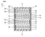
- FIG. 1A is a schematic cross-sectional view of a solid-state battery schematically showing a solid-state battery according to an embodiment of the present invention.
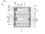
- FIG. 1B is a schematic cross-sectional view of a solid-state battery schematically showing a solid-state battery according to another embodiment of the present invention.
- FIG. 2 is a schematic cross-sectional view of the negative electrode layer for explaining the conductive path of the negative electrode layer in the solid-state battery of the present invention.
- FIG. 3A is a schematic cross-sectional view of the conductive auxiliary agent schematically showing an example of the conductive auxiliary agent having a long and narrow cross-sectional view contained in the negative electrode layer in the solid-state battery of the present invention.
- FIG. 1A is a schematic cross-sectional view of a solid-state battery schematically showing a solid-state battery according to an embodiment of the present invention.
- FIG. 1B is a schematic cross-sectional view of a solid-state battery schematically showing a solid-state battery according to
- FIG. 3B is a schematic cross-sectional view of the conductive auxiliary agent schematically showing another example of the conductive auxiliary agent having a long and narrow cross-sectional view contained in the negative electrode layer in the solid-state battery of the present invention.
- FIG. 4A is a schematic cross-sectional view of the solid-state battery manufactured in the examples according to the embodiment of the present invention, which schematically shows the solid-state battery (main surface current collecting structure).
- FIG. 4B is a schematic cross-sectional view of a solid-state battery schematically showing a solid-state battery (end face current collecting structure) according to another embodiment of the present invention manufactured in the examples.
- FIG. 5 is a schematic cross-sectional view of the negative electrode layer for explaining the conductive path of the negative electrode layer in the solid-state battery of the prior art.
- Solid-state battery refers to a battery in which its components (particularly the electrolyte layer) are composed of solids in a broad sense, and in a narrow sense, the components (particularly all components) are composed of solids. Refers to the "all-solid-state battery” that is configured.
- the “solid-state battery” as used herein includes a so-called “secondary battery” capable of repeating charging and discharging, and a “primary battery” capable of only discharging.
- the “solid-state battery” is preferably a "secondary battery”.
- the “secondary battery” is not overly bound by its name and may include, for example, a "storage device”.
- the solid-state battery of the present invention includes a positive electrode layer 1, a negative electrode layer 2, and a solid electrolyte layer 3, and usually, the positive electrode layer and the negative electrode layer are laminated via the solid electrolyte layer. It has a laminated structure.
- the positive electrode layer and the negative electrode layer may be laminated in two or more layers as long as a solid electrolyte layer is provided between them.
- the solid electrolyte layer is in contact with the positive electrode layer and the negative electrode layer and is sandwiched between them.
- the positive electrode layer and the solid electrolyte layer may be integrally sintered with each other, and / or the negative electrode layer and the solid electrolyte layer may be integrally sintered with each other.
- integral sintering of sintered bodies means that two or more members (particularly layers) adjacent to or in contact with each other are joined by sintering.
- the two or more members (particularly the layer) may be integrally sintered while being a sintered body.
- 1A and 1B are schematic cross-sectional views of a solid-state battery schematically showing a solid-state battery according to an embodiment of the present invention.
- the solid-state battery of the present invention includes a positive electrode current collector layer 11, a negative electrode current collector layer 21, a positive electrode current collector (not shown), a negative electrode current collector 22, and an electrode separation unit 15, 25, a protective layer 5, and end face electrodes 10 and 20 may be further provided.
- the solid-state battery of FIG. 1B is similar to the solid-state battery of FIG. 1A except that the negative electrode layer 2 has an end face current collecting structure.
- the end face current collecting structure of the negative electrode layer 2 of FIG. 1B is a negative electrode terminal via the negative electrode current collecting section 22 while being in contact with the negative electrode current collecting section 22 at the end face of the negative electrode layer 2. It is a structure that is electrically connected to 20.
- the negative electrode layer 2 has a main surface current collecting structure.
- the main surface current collecting structure of the negative electrode layer 2 of FIG. 1A is mainly via the negative electrode current collecting layer 21 while being in contact with the negative electrode current collecting layer 21 on the main surface of the negative electrode layer 2. It is a structure that is electrically connected to the negative electrode terminal 20.
- the negative electrode layer 2 contains a conductive auxiliary agent and a negative electrode active material, and may further contain a solid electrolyte.
- the conductive auxiliary agent, the negative electrode active material, and the solid electrolyte all preferably have the form of a sintered body.
- the negative electrode layer contains a conductive auxiliary agent, a negative electrode active material and a solid electrolyte
- the negative electrode layer is bonded between the negative electrode active material particles by the conductive auxiliary agent and the solid electrolyte, and the conductive auxiliary agent, the negative electrode active material particles and the solid.
- the electrolyte preferably has the form of a sintered body, which is bonded to each other by sintering.
- the negative electrode layer contains a conductive auxiliary agent having an elongated cross-sectional view as a conductive auxiliary agent in an area ratio of 7% or more and 28% or less with respect to the negative electrode layer, and is preferable from the viewpoint of further improving the utilization rate of the negative electrode active material.
- the content is 7.5% or more and 25% or less, more preferably 10% or more and 23% or less, and further preferably 15% or more and 22% or less.
- the negative electrode layer 2 contains the conductive auxiliary agent 200 having an elongated cross-sectional view, so that the conductive path p can be efficiently formed.
- FIG. 2 is a schematic cross-sectional view of the negative electrode layer for explaining the conductive path of the negative electrode layer in the solid-state battery of the present invention.
- the content of the conductive auxiliary agent having an elongated cross-sectional view with respect to the total conductive auxiliary agent is not particularly limited, and is usually 35% or more (particularly 35% or more and 100% or less) in terms of the area ratio to the total conductive auxiliary agent. From the viewpoint of further improving the utilization rate of the negative electrode active material, it is preferably 50% or more and 95% or less, and more preferably 70% or more and 90% or less.
- the content of the conductive auxiliary agent in the elongated cross-sectional shape is the value of the area ratio of the conductive auxiliary agent in the elongated shape in the cross-sectional view.
- the content of the conductive auxiliary agent having an elongated cross-sectional shape is the area of the conductive auxiliary agent having an elongated cross-sectional shape confirmed in the negative electrode layer of the SEM image (photograph) showing the laminated structure (cross-sectional structure) of the solid-state battery. It is a ratio value.
- the content of the conductive auxiliary agent having an elongated cross-sectional view is an average value of values measured at any 10 points, and is an area ratio to the negative electrode layer (that is, the total area of each visual field in the negative electrode layer) or It is expressed as the area ratio of the conductive auxiliary agent having an elongated cross-sectional view to the total conductive auxiliary agent (that is, the area of the total conductive auxiliary agent in each visual field).
- a conductive auxiliary agent having an elongated shape in cross-sectional view means a conductive auxiliary agent having an elongated shape in cross-sectional view of the negative electrode layer.
- a conductive auxiliary agent having an elongated shape in a cross-sectional view has a shape having a long direction in a cross-sectional view of the negative electrode layer.
- the "cross-sectional view" referred to in the present specification is a form when viewed from a direction substantially perpendicular to the thickness direction based on the stacking direction of each layer constituting the solid-state battery (in short, a surface parallel to the thickness direction). It is based on the form when cut out in) and includes a cross-sectional view.
- the "cross-sectional view” may be based on a surface parallel to the thickness direction based on the stacking direction of each layer constituting the solid-state battery, and may be based on a form cut out on a surface perpendicular to the positive electrode terminal and the negative electrode terminal.
- a cross-sectional view as shown in FIGS. 1A and 1B can be mentioned. Therefore, the "SEM image showing the laminated structure (cross-sectional structure) of the solid-state battery" used for various measurements may be an image based on the cross-sectional view as described above.
- the conductive auxiliary agent capable of having an elongated shape in cross section
- a flat conductive auxiliary agent, a fibrous conductive auxiliary agent, or a mixture thereof is used as the conductive auxiliary agent.
- a simple metal powder is used as the conductive auxiliary agent
- it is difficult to obtain a sufficient utilization rate of the negative electrode active material because the metal powder is beaded (particularly spherical) in the negative electrode layer at the time of sintering.
- a flat or fibrous conductive auxiliary agent is used as the conductive auxiliary agent, spheroidization (particularly spherical formation) is suppressed during sintering, and the conductive auxiliary agent has an elongated cross-sectional view after sintering.
- the conductive auxiliary agent having an elongated cross-sectional view corresponds to a flat conductive auxiliary agent, a fibrous conductive auxiliary agent, or a mixture thereof by disassembling the solid-state battery.
- the flat shape is a shape in which particles are crushed, and is also called a "scale shape” or a "flat shape”.
- the fibrous shape includes a "linear" shape or a "rod shape", and may be, for example, a shape possessed by so-called metal nanowires.
- the conductive auxiliary agent Even when only a simple metal powder (for example, a spherical conductive auxiliary agent) is used as the conductive auxiliary agent, some of the metal powders are bonded to each other by sintering in the negative electrode layer so as to have an elongated shape in cross section. May become.
- the negative electrode layer contains only metal powder in a proportion of 28% or less with respect to the negative electrode layer
- the content of the conductive auxiliary agent having an elongated cross-sectional view is usually 4% or less (or total conductivity) with respect to the negative electrode layer.
- the area ratio to the auxiliary agent is 10% or less), and the above-mentioned conductive auxiliary agent content having an elongated cross-sectional view as in the present invention cannot be achieved.
- the conductive auxiliary agent having an elongated shape in cross-sectional view is specifically defined in the negative electrode layer by the longest dimension a and the short side length (thickness dimension) b for one conductive auxiliary agent 200a in cross-sectional view, as shown in FIG. 3A.
- the depth length c (that is, the dimension in the front-back direction on FIG. 3A) (not shown) is not particularly limited.
- the longest dimension a is a dimension that defines the maximum length in a cross-sectional view.
- the short side length b is a dimension that defines the maximum length (or maximum thickness) in the direction perpendicular to the longest dimension a direction in cross-sectional view.
- the short side length b usually satisfies a> b.
- the depth length c is a dimension that defines the maximum length in the direction perpendicular to the cross-sectional view, and usually satisfies c ⁇ 2b (particularly 2a ⁇ c ⁇ 2b) in the case of a flat shape and 2b> c in the case of a fibrous shape. (Especially 2b> c> 0.5b) is satisfied.
- the slender shape in cross-sectional view specifically refers to a shape having a / b of 2.0 or more (particularly 2.0 or more and 20.0 or less).
- FIG. 3A is a schematic cross-sectional view of the conductive auxiliary agent schematically showing an example of the conductive auxiliary agent having a long and narrow cross-sectional view contained in the negative electrode layer in the solid-state battery of the present invention.
- the slender shape in cross section includes a bent slender shape with a bent portion.
- the bent elongated shape has the longest dimension a and the short side length (longest dimension a) and the short side length (for one conductive auxiliary agent 200b in the negative electrode layer, while having one or more bent portions 201 in the negative electrode layer.
- the shape is defined by the thickness dimension) b, and the depth length c (that is, the dimension in the front and back directions on FIG. 3B) (not shown) is not particularly limited.
- the longest dimension a is a dimension that defines the maximum length in a cross-sectional view.
- the short side length b is a dimension that defines the maximum length (or maximum thickness) in the direction perpendicular to the longest dimension a direction in cross-sectional view.
- the depth length c is a dimension that defines the maximum length in a plan view perpendicular to a cross-sectional view.
- the a, b and c in the bent elongated shape (eg, FIG. 3B) and their relationships are similar to those in the simple cross-sectional elongated shape (eg, FIG. 3A).
- FIG. 3B is a schematic cross-sectional view of the conductive auxiliary agent schematically showing another example of the conductive auxiliary agent having a long and narrow cross-sectional view contained in the negative electrode layer in the solid-state battery of the present invention.
- the average aspect ratio (the longest dimension a / short side length b described above) is usually 2.0 or more (particularly 2.0 or more and 20.0 or less) for the conductive auxiliary agent having an elongated shape in the negative electrode layer. From the viewpoint of further improving the utilization rate of the active material, it is preferably 2.0 or more and 15.0 or less, more preferably 2.5 or more and 10.0 or less, and further preferably 3.0 or more and 8.0 or less.
- the average aspect ratio (a / b) of the elongated conductive auxiliary agent is any 100 cross-sectional views confirmed in the negative electrode layer of the SEM image (photograph) showing the laminated structure (cross-sectional structure) of the solid-state battery.
- the average value based on the elongated conductive auxiliary agent is used.
- the average short side length b of the conductive auxiliary agent having an elongated cross-sectional view in the negative electrode layer is not particularly limited, and is preferably 0.1 ⁇ m or more and 4.0 ⁇ m or less from the viewpoint of further improving the utilization rate of the negative electrode active material. It is preferably 0.2 ⁇ m or more and 2.0 ⁇ m or less, more preferably 0.3 ⁇ m or more and 1.5 ⁇ m or less, and particularly preferably 0.3 ⁇ m or more and 1.0 ⁇ m or less.
- the average short side length b of the conductive auxiliary agent having an elongated cross-sectional shape is any 100 elongated shapes confirmed in the negative electrode layer of the SEM image (photograph) showing the laminated structure (cross-sectional structure) of the solid-state battery.
- the average value based on the conductive auxiliary agent is used.
- the average depth length c of the conductive auxiliary agent having an elongated cross-sectional view in the negative electrode layer is not particularly limited, and may be, for example, 0.1 ⁇ m or more and 10.0 ⁇ m or less.
- the average depth length c of the conductive auxiliary agent having an elongated cross-sectional view in the negative electrode layer is usually 0.1 ⁇ m or more and 20 ⁇ m or less.
- the average depth length c of the conductive auxiliary agent having an elongated cross-sectional view in the negative electrode layer is usually 0.1 ⁇ m or more and 10.0 ⁇ m or less.
- the average depth length c of the elongated conductive auxiliary agent in the cross-sectional view is in the negative electrode layer of the three-dimensional image created from 100 SEM images taken at intervals of 0.1 ⁇ m showing the laminated structure (cross-sectional structure) of the solid-state battery.
- An average value based on any 100 conductive auxiliary agents having an elongated cross-sectional view confirmed in the above can be used.
- the conductive auxiliary agent having an orientation angle of 30 ° or less is preferably 20 in area ratio to the total conductive auxiliary agent from the viewpoint of further improving the utilization rate of the negative electrode active material. It is contained in% or more (particularly 20% or more and 100% or less), more preferably 50% or more and 90% or less, further preferably 55% or more and 75% or less, and most preferably 61% or more and 66% or less.
- the orientation angle of the elongated conductive auxiliary agent in cross-sectional view is the same when the solid-state battery is allowed to stand so that the stacking direction L of the positive electrode layer, the solid electrolyte layer, the negative electrode layer, etc. is perpendicular to the horizontal direction. It is the absolute value of the angle (particularly the smaller angle) formed by the longest dimension a direction and the horizontal direction of the conductive auxiliary agent. For example, assuming that the vertical direction of FIG. 3A is parallel to the stacking direction L, the orientation angle of the conductive auxiliary agent 200a having an elongated cross-sectional view is 0 °. Further, for example, assuming that the vertical direction of FIG.
- the orientation angle of the conductive auxiliary agent 200b having an elongated cross-sectional view is ⁇ .
- the conductive auxiliary agent used in the present invention has an elongated shape in cross-sectional view, and the negative electrode layer containing the conductive auxiliary agent having an elongated cross-sectional view has an ultrathin thickness described later.
- Most of the auxiliaries eg, 50% or more in area ratio, especially 60% or more usually have an orientation angle of 30 ° or less in the negative electrode layer.
- the orientation angle of the elongated conductive auxiliary agent in cross-sectional view uses the value confirmed in the negative electrode layer of the SEM image (photograph) showing the laminated structure (cross-sectional structure) of the solid-state battery.
- the content of the conductive auxiliary agent having an orientation angle of 30 ° or less in the negative electrode layer with respect to the total conductive auxiliary agent is the SEM image (photograph) showing the laminated structure (cross-sectional structure) of the solid-state battery. It is a value of the area ratio of the conductive auxiliary agent having an elongated shape with an orientation angle of 30 ° or less, which is confirmed in the negative electrode layer, to the total conductive auxiliary agent. More specifically, the content of the conductive auxiliary agent having an elongated shape with an orientation angle of 30 ° or less is the average value of the values measured at any 10 points, and is the total conductive auxiliary agent (that is, the total conductivity in each visual field). It is expressed as the area ratio of the conductive auxiliary agent having an elongated cross-sectional view with an orientation angle of 30 ° or less with respect to the area of the auxiliary agent).
- the elongated conductive auxiliary agent in cross section is composed of a metal material.
- metal materials that can form a conductive auxiliary agent having an elongated shape in cross section include Ag (silver), Au (gold), Pd (palladium), Pt (platinum), Cu (copper), Sn (tin), and Ni ( Included is one or more metallic materials selected from the group consisting of nickel) and alloys thereof.
- the conductive auxiliary agent having an elongated cross-sectional view is preferably composed of silver from the viewpoint of further improving the utilization rate of the negative electrode active material.
- the negative electrode layer may further contain a conductive auxiliary agent other than the conductive auxiliary agent having an elongated cross-sectional view.
- a conductive auxiliary agent for example, spherical conductive auxiliary agents composed of the same metal material as the metal material constituting the above-mentioned conductive auxiliary agent having an elongated cross-sectional view, acetylene black, Ketjen black, Super P (registered trademark). ), Carbon materials such as carbon nanotubes such as VGCF (registered trademark), and the like.
- the total conductive auxiliary agent containing the conductive auxiliary agent having an elongated cross-sectional view and other conductive auxiliary agents is preferably 30% in the area ratio with respect to the negative electrode layer from the viewpoint of further improving the utilization rate of the negative electrode active material. It is contained below (particularly 5% or more and 30% or less), more preferably 12% or more and 30% or less, and further preferably 18% or more and 28% or less.
- the value of the area ratio of the total conductive auxiliary agent is used.
- the content of the total conductive auxiliary agent is a value of the area ratio of the total conductive auxiliary agent confirmed in the negative electrode layer of the SEM image (photograph) showing the laminated structure (cross-sectional structure) of the solid-state battery.
- the content of the total conductive auxiliary agent is an average value of the values measured at any 10 points, and is the ratio of the area of the total conductive auxiliary agent to the total area of each visual field in the negative electrode layer.
- the negative electrode layer is a layer that can occlude and release metal ions, and is preferably a layer that can occlude and release lithium ions.
- the negative electrode active material contained in the negative electrode layer is not particularly limited, and the molar ratio of Li (lithium) to V (vanadium) is 2.0 or more (from the viewpoint of further improving the utilization rate of the negative electrode active material and improving the discharge capacity). In particular, it is preferable to contain a negative electrode active material of 2 or more and 10 or less).
- the molar ratio of Li to V in the negative electrode active material is preferably 2 or more and 6 or less (particularly 2 or more and 4 or less) from the viewpoint of further improving the utilization rate of the negative electrode active material.
- the negative electrode layer contains a negative electrode active material having such a molar ratio.
- the spheroidization for example, spheroidization
- the conductive path p' is particularly likely to break, and the utilization rate of the negative electrode active material is further lowered.
- the negative electrode layer contains such a negative electrode active material, the breakage of the conductive path can be sufficiently suppressed, and as a result, the negative electrode at the time of charging and discharging with a smaller amount of the conductive auxiliary agent.
- the utilization rate of active materials can be improved more sufficiently. Therefore, when the negative electrode layer contains the negative electrode active material having the above molar ratio, the effect of forming the conductive auxiliary agent in a slender cross-sectional view is particularly high in the present invention.
- the solid electrolyte layer contains a solid electrolyte having a LISION type structure, as described later, the solid is solid.
- the LISION type solid electrolyte of the electrolyte layer contains V, even better bondability can be obtained between the solid electrolyte layer and the negative electrode layer.
- the side reaction at the time of co-stituting between the negative electrode active material contained in the negative electrode layer and the LISION type solid electrolyte in the solid electrolyte layer is suppressed, and the reversible capacity of the solid state battery can be increased. As a result, the utilization rate of the negative electrode active material at the time of charging / discharging can be sufficiently increased.
- the negative electrode active material is described by the general formula (1): from the viewpoint of further improving the utilization rate of the negative electrode active material. It is preferable to have an average chemical composition represented by. With such a composition, the reactivity of the solid electrolyte layer with the LISION type solid electrolyte can be further sufficiently reduced.
- the negative electrode active material used in the present invention further fully expresses its capacity by the redox of V. Therefore, in order to obtain a sufficient reversible capacity, the V amount y is preferably 0.5 ⁇ y ⁇ 1.0 as described later.
- A is one or more elements selected from the group consisting of Na (sodium), K (potassium), Mg (magnesium), Ca (calcium), and Zn (zinc).
- B is Zn (zinc), Al (aluminum), Ga (gallium), Si (silicon), Ge (germanium), Sn (tin), P (phosphorus), As (arsenic), Ti (tungsten), Mo ( One or more elements selected from the group consisting of molybdenum), W (tungsten), Fe (iron), Cr (chromium), and Co (cobalt).
- x has a relationship of 0 ⁇ x ⁇ 1.0, preferably a relationship of 0 ⁇ x ⁇ 0.5, and more preferably a relationship of 0 ⁇ x ⁇ 0.1.
- y has a relationship of 0.5 ⁇ y ⁇ 1.0, preferably a relationship of 0.55 ⁇ y ⁇ 1.0, and more preferably 1.
- a is the average valence of A.
- the average valence of A is (n1 ⁇ ) when, for example, n1 elements X having a valence a +, n2 elements Y having a valence b +, and n3 elements Z having a valence c + are recognized as A.
- b is the average valence of B.
- the average valence of B is, as B, for example, when n1 elements X having a valence a +, n2 elements Y having a valence b +, and n3 elements Z having a valence c + are recognized, the above-mentioned A It is the same value as the average valence of.
- A is one or more elements selected from the group consisting of Al and Zn.
- B is one or more, particularly two, elements selected from the group consisting of Si and P.
- x has a relationship of 0 ⁇ x ⁇ 0.06, and is more preferably 0.
- y has a relationship of 0.55 ⁇ y ⁇ 1.0, more preferably 0.8 ⁇ y ⁇ 1.0, and even more preferably 1.
- a is the average valence of A.
- b is the average valence of B.
- the negative electrode active material include, for example, Li 3 VO 4 , Li 3.2 (V 0.8 Si 0.2 ) O 4 , (Li 3.1 Al 0.03 ) (V 0.8 Si). 0.2 ) O 4 , (Li 3.1 Zn 0.05 ) (V 0.8 Si 0.2 ) O 4 , Li 3.3 (V 0.6 P 0.1 Si 0.3 ) O 4 , Li 3.18 (V 0.77 P 0.05 Si 0.18 ) O 4 , Li 3.07 (V 0.90 P 0.03 Si 0.07 ) O 4 , Li 3.22 (V 0) .72 P 0.06 Si 0.22 ) O 4 and the like.
- the chemical composition of the negative electrode active material may be an average chemical composition.
- the average chemical composition of the negative electrode active material means the average value of the chemical composition of the negative electrode active material in the thickness direction of the negative electrode layer.
- the average chemical composition of the negative electrode active material is obtained by breaking the solid-state battery and performing composition analysis with EDX using SEM-EDX (energy dispersive X-ray spectroscopy) from the viewpoint that the entire thickness direction of the negative electrode layer fits. It can be analyzed and measured.
- the average chemical composition of the negative electrode active material and the average chemical composition of the solid electrolyte described later can be automatically distinguished and measured according to their compositions in the above composition analysis.
- the negative electrode active material can be produced, for example, by the following method. First, a raw material compound containing a predetermined metal atom is weighed so that the chemical composition has a predetermined chemical composition, and water is added and mixed to obtain a slurry. The slurry can be dried, calcined at 700 ° C. or higher and 1000 ° C. or lower for 4 hours or more and 6 hours or less, and pulverized to obtain a negative electrode active material.
- the chemical composition of the negative electrode active material reflects the chemical composition of the negative electrode active material used at the time of production as it is when high-speed sintering is performed at 750 ° C. for about 1 minute together with the solid electrolyte layer, but the chemical composition is 750 ° C.
- sintering is performed for a long time of about 1 hour, element diffusion into the solid electrolyte layer proceeds, and the amount of V is usually reduced.
- the negative electrode active material preferably has a ⁇ II- Li 3 VO 4 type structure or a ⁇ II- Li 3 VO 4 type structure from the viewpoint of further improving the utilization rate of the negative electrode active material.
- a crystal structure By having such a crystal structure, the reversibility of charge and discharge is improved, and stable cycle characteristics can be obtained. Further, when the active material has a ⁇ II ⁇ Li 3 VO 4 type structure, the bondability with the LISION type solid electrolyte in the solid electrolyte layer is improved, which is more preferable.
- the negative electrode active material has a ⁇ II- Li 3 VO 4 type structure
- the negative electrode active material has a ⁇ II- Li 3 VO 4 type crystal structure
- the negative electrode active material has a ⁇ II- Li 3 VO 4 type structure, which means that the negative electrode active material (particularly its particles) has a so-called ⁇ II- Li 3 VO 4 type crystal structure in X-ray diffraction. It means that one or more major peaks corresponding to the Miller index peculiar to are shown at a predetermined angle of incidence.
- ICDD Card No. 01-073-6058 can be mentioned.
- the negative electrode active material has a ⁇ II- Li 3 VO 4 type structure
- the negative electrode active material has a ⁇ II- Li 3 VO 4 type crystal structure
- the negative electrode active material has a ⁇ II- Li 3 VO 4 type structure, which means that the negative electrode active material (particularly its particles) has a so-called ⁇ II- Li 3 VO 4 type crystal structure in X-ray diffraction.
- ICDD Card No. 01-073-2850 As an example of a negative electrode active material having a ⁇ II ⁇ Li 3 VO 4 type structure, for example, ICDD Card No. 01-073-2850 can be mentioned.
- the average chemical composition and crystal structure of the negative electrode active material in the negative electrode layer usually change due to element diffusion during sintering.
- the negative electrode active material preferably has the above-mentioned average chemical composition and crystal structure in a solid-state battery after being sintered together with the positive electrode layer and the solid electrolyte layer.
- the average particle size of the negative electrode active material is not particularly limited, and may be, for example, 0.01 ⁇ m or more and 20 ⁇ m or less, preferably 0.1 ⁇ m or more and 5 ⁇ m or less.
- the average particle size of the negative electrode active material for example, 10 or more and 100 or less particles can be randomly selected from the SEM image, and the average particle size (arithmetic mean) can be obtained by simply averaging the particles. can.
- the particle size is the diameter of the spherical particle assuming that the particle is perfectly spherical.
- a cross section of a solid-state battery is cut out, a cross-section SEM image is taken using SEM, and then image analysis software (for example, "A image-kun" (manufactured by Asahi Kasei Engineering Co., Ltd.)) is used to cut the particles.
- image analysis software for example, "A image-kun" (manufactured by Asahi Kasei Engineering Co., Ltd.)
- the particle diameter R can be obtained by the following formula.
- the average particle size of the negative electrode active material in the negative electrode layer can be automatically measured by specifying the negative electrode active material by the composition at the time of measuring the average chemical composition described above
- the volume ratio of the negative electrode active material in the negative electrode layer is not particularly limited, and is preferably 20% or more and 80% or less, and is preferably 30% or more and 75% or less, from the viewpoint of further improving the utilization rate of the negative electrode active material. More preferably, it is 30% or more and 60% or less.
- the volume ratio of the negative electrode active material in the negative electrode layer can be measured from the SEM image after the FIB cross-section processing. Specifically, the cross section of the negative electrode layer is observed using SEM-EDX. It is possible to measure the volume ratio of the negative electrode active material by determining that the portion where V is detected from EDX is the negative electrode active material and calculating the area ratio of the above portion.
- the particle shape of the negative electrode active material in the negative electrode layer is not particularly limited, and may be, for example, a spherical shape, a flat shape, or an indefinite shape.
- the negative electrode layer preferably further contains a solid electrolyte, particularly a solid electrolyte having a garnet-type structure. Since the negative electrode layer contains a garnet-type solid electrolyte, the ionic conductivity of the negative electrode layer can be increased, and a high rate can be expected. Further, since a side reaction at the time of co-firing with a negative electrode active material having a Li / V ratio of 2 or more can be suppressed, an improvement in the utilization rate of the negative electrode can be expected. As will be described later, it is preferable that the solid electrolyte layer also further contains a solid electrolyte, particularly a solid electrolyte having a garnet-type structure.
- the solid electrolyte layer contains a garnet-type solid electrolyte, so that the insulating property of the solid electrolyte layer can be improved. It is thought that this is because the garnet-type solid electrolyte is difficult to be reduced during charging and discharging, so it is difficult for electrons to be injected, and the degree of flexibility of the LISION-type solid electrolyte in the solid electrolyte increases, resulting in an increase in electron resistance. Be done. Further, since a side reaction at the time of co-firing with a negative electrode active material having a Li / V ratio of 2 or more can be suppressed, an improvement in the utilization rate of the negative electrode can be expected.
- At least one (particularly both) of the negative electrode layer or the solid electrolyte layer preferably contains a solid electrolyte having a garnet-type structure.
- one of the negative electrode layer and the solid electrolyte layer may contain a solid electrolyte having a garnet-type structure, or both of them are garnet. It means that it may contain a solid electrolyte having a mold structure.
- the solid electrolyte has a garnet-type structure
- a solid electrolyte having a garnet-type structure means that, in X-ray diffraction, the solid electrolyte incidents one or more major peaks corresponding to the Miller index inherent in the so-called garnet-type crystal structure. Means to show in angle.
- the solid electrolyte having a garnet-type structure is described by the general formula (2): It is preferable to have an average chemical composition represented by.
- the negative electrode layer contains a solid electrolyte having the above average chemical composition, further improvement in the utilization rate of the negative electrode active material can be achieved.
- A is one or more elements selected from the group consisting of Ga (gallium), Al (aluminum), Mg (magnesium), Zn (zinc), and Sc (scandium).
- B is one or more elements selected from the group consisting of Nb (niobium), Ta (tantalum), W (tungsten), Te (tellurium), Mo (molybdenum), and Bi (bismuth).
- x has a relationship of 0 ⁇ x ⁇ 0.5.
- y has a relationship of 0 ⁇ y ⁇ 2.0.
- a is the average valence of A, which is the same as the average valence of A in the formula (1).
- b is the average valence of B, which is the same as the average valence of B in the formula (1).
- A is one or more elements selected from the group consisting of Ga and Al.
- B is one or more elements selected from the group consisting of Nb, Ta, W, Mo, and Bi.
- x has a relationship of 0 ⁇ x ⁇ 0.3, preferably 0.
- y has a relationship of 0 ⁇ y ⁇ 1.0, preferably a relationship of 0 ⁇ y ⁇ 0.7, more preferably a relationship of 0.3 ⁇ y ⁇ 0.7, and is preferably 0.5.
- .. a is the average valence of A.
- b is the average valence of B.
- solid electrolyte represented by the general formula (2) examples include (Li 6.4 Ga 0.05 Al 0.15 ) La 3 Zr 2 O 12 and (Li 6.4 Ga 0.2 ) La. 3 Zr 2 O 12 , Li 6.4 La 3 (Zr 1.6 Ta 0.4 ) O 12 , (Li 6.4 Al 0.2 ) La 3 Zr 2 O 12 , Li 6.5 La 3 (Zr) Examples thereof include 1.5 Mo 0.25 ) O 12 and Li 6.5 La 3 (Zr 1.5 Ta 0.5 ) O 12.
- the average chemical composition of the solid electrolyte (particularly the solid electrolyte having a garnet-type structure) in the negative electrode layer means the average value of the chemical composition of the solid electrolyte in the thickness direction of the negative electrode layer.
- the average chemical composition of the solid electrolyte is analyzed by breaking the solid-state battery and performing composition analysis with EDX using SEM-EDX (energy dispersive X-ray spectroscopy) with a view that the entire thickness direction of the negative electrode layer fits. And measurable.
- the average chemical composition of the negative electrode active material and the average chemical composition of the solid electrolyte can be automatically distinguished and measured according to their compositions in the above composition analysis.
- the solid electrolyte of the negative electrode layer can be obtained by the same method as the negative electrode active material except that a raw material compound containing a predetermined metal atom is used, or can be obtained as a commercially available product.
- the average chemical composition and crystal structure of the solid electrolyte in the negative electrode layer usually change due to element diffusion during sintering.
- the solid electrolyte preferably has the above-mentioned average chemical composition and crystal structure in the solid-state battery after being sintered together with the positive electrode layer and the solid electrolyte layer.
- the volume ratio of the solid electrolyte (particularly the solid electrolyte having a garnet-type structure) in the negative electrode layer is not particularly limited, and is 10% from the viewpoint of the balance between further improving the utilization rate of the negative electrode active material and increasing the energy density of the solid battery. It is preferably 50% or more, and more preferably 20% or more and 40% or less.
- the volume ratio of the solid electrolyte in the negative electrode layer can be measured by the same method as the volume ratio of the negative electrode active material. Being a garnet-type solid electrolyte is based on the site where Zr and / or La is detected by EDX.
- the negative electrode layer may further contain, for example, a sintering aid, a conductive auxiliary agent, and the like, in addition to the negative electrode active material and the solid electrolyte.
- the negative electrode layer contains a sintering aid, it can be densified even during sintering at a lower temperature, and element diffusion at the negative electrode active material / solid electrolyte layer interface can be suppressed.
- a sintering aid known in the field of solid-state batteries can be used.
- the composition of the sintering aid contains at least Li (lithium), B (boron), and O (oxygen) with respect to B.
- the molar ratio of Li (Li / B) is preferably 2.0 or more.
- these sintering aids have low fusible properties, and by advancing liquid phase sintering, the negative electrode layer can be densified at a lower temperature. Further, by adopting the above composition, the side reaction between the sintering aid and the LISION type solid electrolyte used in the present invention at the time of co-sintering can be further suppressed.
- the sintering aid that satisfies these conditions include Li 3 BO 3 , (Li 2.7 Al 0.3 ) BO 3 , and Li 2.8 (B 0.8 C 0.2 ) O 3 . Of these, it is particularly preferable to use BO 3 having a particularly high ionic conductivity (Li 2.7 Al 0.3).
- the volume ratio of the sintering aid in the negative electrode layer is not particularly limited, and may be 0.1 or more and 10% or less from the viewpoint of further improving the utilization rate of the negative electrode active material and increasing the energy density of the solid-state battery. It is preferably 1% or more and 7% or less, more preferably.
- the volume ratio of the sintering aid in the negative electrode layer can be measured by the same method as the volume ratio of the negative electrode active material.
- B can be focused on as a detection element in EDX, which is determined to be in the region of the sintering aid.
- the porosity is not particularly limited, and is preferably 20% or less, more preferably 15% or less, still more preferably 10% or less, from the viewpoint of further improving and further reducing the utilization rate of the negative electrode active material.
- the porosity of the negative electrode layer the value measured from the SEM image after the FIB cross-section processing is used.
- the negative electrode layer usually has a thickness of 2 ⁇ m or more and 100 ⁇ m or less, preferably 2 ⁇ m or more and 50 ⁇ m or less.
- the negative electrode layer 2 may have an end face current collecting structure as shown in FIG. 1A, or may have a main surface current collecting structure as shown in FIG. 1B.
- the negative electrode layer preferably has an end face current collecting structure from the viewpoint of further improving the capacitance density (for example, energy density).
- the fact that the negative electrode layer 2 has an end face current collecting structure means that the negative electrode layer 2 has a structure that collects current on the end face 2a (particularly only the end face) of the negative electrode layer 2 on the negative electrode terminal 20 side.
- the negative electrode layer 2 is in contact with the negative electrode current collecting unit 22 at the end surface 2a (particularly only the end surface) of the negative electrode layer 2 on the negative electrode terminal 20 side, and the negative electrode current collecting unit 22 It may be electrically connected to the negative electrode terminal 20 via the negative electrode terminal 20, or is directly and electrically connected to the negative electrode terminal 20 on the negative electrode terminal 20 side at the end surface 2a (particularly only the end surface) of the negative electrode layer 2. May be. As shown in FIG.
- the negative electrode layer 2 collects negative electrode current from the negative electrode layer 2 at the end surface 2a (particularly only the end surface) on the negative electrode terminal 20 side from the viewpoint of ensuring sufficient electrical connection with the negative electrode terminal 20. It is preferable that the negative electrode terminal 20 is electrically connected to the negative electrode terminal 20 via the negative electrode current collecting unit 22 while being in contact with the unit 22.
- the negative electrode layer 2 and the negative electrode current collecting portion 22 are mutually end faces. As a result, they have a configuration in which they are adjacent to each other in the direction perpendicular to the stacking direction in the cross-sectional view.
- the negative electrode layer 2 and the negative electrode current collector 22 have a configuration in which they are adjacent to each other in the direction perpendicular to the stacking direction even in a plan view.
- the negative electrode current collecting unit 22 is usually in the stacking direction L in the negative electrode layer 2. It has an upper surface 2b and a flush upper surface 22b, and also has a flush lower surface 2c and a flush lower surface 22c in the stacking direction L in the negative electrode layer 2.
- Flip is a state in which there is no step between the two faces.
- the two surfaces are the upper surface 2b of the negative electrode layer 2 and the upper surface 22b of the negative electrode current collector 22, and the lower surface 2c of the negative electrode layer 2 and the lower surface 22c of the negative electrode current collector 22.
- the fact that the negative electrode layer 2 has a main surface current collecting structure means that the negative electrode layer 2 has a structure that collects current on the main surface of the negative electrode layer.
- the negative electrode layer 2 is electrically connected to the negative electrode terminal 20 via the negative electrode current collector layer 21 while being in contact with the negative electrode current collector layer 21 on the main surface 2x of the negative electrode layer 2.
- the negative electrode current collecting layer 21 may be laminated on the main surface of the negative electrode layer 2, and / or the negative electrode layer 2 is laminated on the main surface of the negative electrode current collecting layer 21. May be.
- the main surface is a surface having a relatively large area, and more specifically, an upper surface and / or a lower surface perpendicular to the stacking direction. Collecting electricity on the main surface means that electrons come and go mainly from the main surface.
- the negative electrode layer 2 is directly electrically connected to the negative electrode terminal 20 on the negative electrode terminal 20 side. May be electrically connected to.
- the negative electrode layer 2 may be laminated on both main surfaces of the negative electrode current collecting layer 21 as shown in FIG. 1A, or may be laminated on one main surface. May be done.
- the negative electrode current collector layer 21 and the negative electrode current collector 22 may further include a solid electrolyte.
- the negative electrode current collector layer 21 and the negative electrode current collector 22 are made of a sintered body containing at least a conductive material and a solid electrolyte.
- a material having a relatively large conductivity is usually used, and for example, a carbon material, silver, palladium, gold, platinum, aluminum, or copper. It is preferable to use at least one selected from the group consisting of and nickel.
- the solid electrolyte that may be contained in the negative electrode current collecting layer 21 and the negative electrode current collecting unit 22 may be selected from the same solid electrolytes as the solid electrolyte that may be contained in the negative electrode layer described above.
- the negative electrode current collecting layer 21 and the negative electrode current collecting unit 22 preferably have a sintered body form from the viewpoint of reducing the manufacturing cost of the solid-state battery and the internal resistance of the solid-state battery by the integral sintering.
- the negative electrode current collector layer 21 and the negative electrode current collector 22 have the form of a sintered body, for example, the negative electrode current collector layer 21 and the negative electrode current collector 22 are sintered assist in addition to the above-mentioned conductive material and solid electrolyte. It may be composed of a sintered body further containing an agent.
- the sintering aid contained in the negative electrode current collector layer 21 and the negative electrode current collector 22 may be selected from, for example, the same materials as the sintering aid that can be contained in the negative electrode layer.
- the thickness of the negative electrode current collector layer is not particularly limited, and may be, for example, 1 ⁇ m or more and 10 ⁇ m or less, preferably 1 ⁇ m or more and 5 ⁇ m or less, and particularly 1 ⁇ m or more and 3 ⁇ m or less.
- the thickness of the negative electrode current collector may usually be the same as that of the negative electrode layer.
- the negative electrode layer is a layer that can also be called a "negative electrode active material layer”.
- the negative electrode layer is preferably a layer capable of occluding and releasing lithium ions as described above, but the present invention does not prevent the negative electrode layer from being a layer capable of occluding and releasing sodium ions.
- the positive electrode layer 1 is not particularly limited.
- the positive electrode layer 1 contains a positive electrode active material.
- the positive electrode layer 1 preferably has the form of a sintered body containing positive electrode active material particles.
- the positive electrode layer is a layer that can occlude and release metal ions, and is preferably a layer that can occlude and release lithium ions.
- the positive electrode active material is not particularly limited, and a positive electrode active material known in the field of solid-state batteries can be used.
- Examples of the positive electrode active material include lithium-containing phosphoric acid compound particles having a pearcon-type structure, lithium-containing phosphoric acid compound particles having an olivine-type structure, lithium-containing layered oxide particles, and lithium-containing oxide particles having a spinel-type structure. Can be mentioned.
- Specific examples of the lithium-containing phosphoric acid compound having a Nashikon-type structure preferably used include Li 3 V 2 (PO 4 ) 3 .
- lithium-containing phosphate compound having preferably olivine structure used Li 3 Fe 2 (PO 4 ) 3, LiMnPO 4 , and the like.
- lithium-containing layered oxide particles preferably used include LiCoO 2 , LiCo 1/3 Ni 1/3 Mn 1/3 O2, and the like.
- Specific examples of the lithium-containing oxide having a spinel-type structure preferably used include LiMn 2 O 4 , LiNi 0.5 Mn 1.5 O 4 , Li 4 Ti 5 O 12. and the like.
- lithium-containing layered oxides such as LiCoO 2 , LiCo 1/3 Ni 1/3 Mn 1/3 O 2 and the like are used as positive electrode active materials. Is more preferably used. In addition, only one kind of these positive electrode active material particles may be used, or a plurality of kinds may be mixed and used.
- the positive electrode active material having a pear-con type structure in the positive electrode layer means that the positive electrode active material (particularly its particles) has a crystal structure that can be recognized as the crystal structure of the above. It means that one or more major peaks corresponding to the mirror index peculiar to the so-called Nashikon type crystal structure are shown at a predetermined incident angle. Examples of the positive electrode active material having a Nashikon type structure preferably used are exemplified above. Examples of the compound.
- the chemical composition of the positive electrode active material may be the average chemical composition.
- the average chemical composition of the positive electrode active material means the average value of the chemical composition of the positive electrode active material in the thickness direction of the positive electrode layer.
- the average chemical composition of the positive electrode active material is obtained by breaking the solid-state battery and performing composition analysis with EDX using SEM-EDX (energy dispersive X-ray spectroscopy) from the viewpoint that the entire thickness direction of the positive electrode layer fits. It can be analyzed and measured.
- the positive electrode active material can be obtained by the same method as the negative electrode active material except that a raw material compound containing a predetermined metal atom is used, or can be obtained as a commercially available product.
- the chemical composition and crystal structure of the positive electrode active material in the positive electrode layer usually change due to element diffusion during sintering.
- the positive electrode active material preferably has the above-mentioned chemical composition and crystal structure in a solid-state battery after being sintered together with the negative electrode layer and the solid electrolyte layer.
- the average particle size of the positive electrode active material is not particularly limited, and may be, for example, 0.01 ⁇ m or more and 10 ⁇ m or less, preferably 0.05 ⁇ m or more and 4 ⁇ m or less.
- the average particle size of the positive electrode active material can be obtained by the same method as the average particle size of the negative electrode active material in the negative electrode layer.
- the average particle size of the positive electrode active material in the positive electrode layer usually reflects the average particle size of the positive electrode active material used at the time of manufacture as it is. In particular, when LCO is used for the positive electrode particles, it is reflected as it is.
- the particle shape of the positive electrode active material in the positive electrode layer is not particularly limited, and may be, for example, a spherical shape, a flat shape, or an indefinite shape.
- the volume ratio of the positive electrode active material in the positive electrode layer is not particularly limited, and is preferably 30% or more and 90% or less, preferably 40% or more and 70% or less, from the viewpoint of further improving the utilization rate of the negative electrode active material. More preferred.
- the positive electrode layer may further contain, for example, a solid electrolyte, a sintering aid, a conductive auxiliary agent, and the like, in addition to the positive electrode active material.
- the type of solid electrolyte contained in the positive electrode layer is not particularly limited.
- Examples of the solid electrolyte contained in the positive electrode layer include solid electrolytes having a garnet-type structure (Li 6.4 Ga 0.2 ) La 3 Zr 2 O 12 and Li 6.4 La 3 (Zr 1.6 Ta 0.4).
- the solid electrolyte of the positive electrode layer can be obtained by the same method as the negative electrode active material except that a raw material compound containing a predetermined metal atom is used, or can be obtained as a commercially available product.
- the average chemical composition and crystal structure of the solid electrolyte in the positive electrode layer usually change due to element diffusion during sintering.
- the solid electrolyte preferably has the above-mentioned average chemical composition and crystal structure in the solid-state battery after being sintered together with the negative electrode layer and the solid electrolyte layer.
- the volume ratio of the solid electrolyte in the positive electrode layer is not particularly limited, and is preferably 20% or more and 60% or less from the viewpoint of further improving the utilization rate of the negative electrode active material and increasing the energy density of the solid state battery. More preferably, it is% or more and 45% or less.
- the same compound as the sintering aid in the negative electrode layer can be used.
- the volume ratio of the sintering aid in the positive electrode layer is not particularly limited, and should be 0.1% or more and 20% or less from the viewpoint of further improving the utilization rate of the negative electrode active material and increasing the energy density of the solid-state battery. Is preferable, and more preferably 1% or more and 10% or less.
- any conductive auxiliary agent known in the field of solid-state batteries can be used.
- conductive auxiliary agents include metal materials such as Ag (silver), Au (gold), Pd (palladium), Pt (platinum), Cu (copper), Sn (tin), and Ni (nickel); And carbon materials such as carbon nanotubes such as acetylene black, Ketjen black, Super P (registered trademark) and VGCF (registered trademark) can be mentioned.
- a conductive auxiliary agent having an elongated cross-sectional view in the negative electrode layer may be used.
- the volume ratio of the conductive auxiliary agent in the positive electrode layer is not particularly limited, and is preferably 10% or more and 50% or less from the viewpoint of further improving the utilization rate of the negative electrode active material and increasing the energy density of the solid-state battery. More preferably, it is 20% or more and 40% or less.
- the porosity is not particularly limited, and from the viewpoint of further improving the utilization rate of the negative electrode active material, it is preferably 20% or less, more preferably 15% or less, still more preferably 10% or less.
- porosity of the positive electrode layer a value measured by the same method as the porosity of the negative electrode layer is used.
- the positive electrode layer 1 may have a main surface current collecting structure as shown in FIGS. 1A and 1B, or may have an end surface current collecting structure.
- the positive electrode layer preferably has a main surface current collecting structure from the viewpoint of reducing the manufacturing cost.
- the fact that the positive electrode layer 1 has a main surface current collecting structure means that the positive electrode layer 1 has a structure that collects current on the main surface of the positive electrode layer.
- the positive electrode layer 1 is in contact with the positive electrode current collector layer 11 on the main surface 1x of the positive electrode layer 1 and is electrically connected to the positive electrode terminal 10 via the positive electrode current collector layer 11. Is connected.
- the positive electrode current collecting layer 11 may be laminated on the main surface of the positive electrode layer 1 and / or the positive electrode layer 1 is laminated on the main surface of the positive electrode current collecting layer 11. May be.
- the main surface is a surface having a relatively large area, and more specifically, an upper surface and / or a lower surface perpendicular to the stacking direction. Collecting electricity on the main surface means that electrons come and go mainly from the main surface.
- the positive electrode layer 1 is directly electrically connected to the positive electrode terminal 10 on the positive electrode terminal 10 side, but is interposed through the positive electrode current collector as in the positive electrode layer having an end face current collecting structure described later. It may be electrically connected to the positive electrode terminal 10.
- the positive electrode layer 1 may be laminated on both main surfaces of the positive electrode current collecting layer 11 or one main surface as shown in FIGS. 1A and 1B. It may be laminated on the surface.
- the fact that the positive electrode layer 1 has an end face current collecting structure means that the positive electrode layer 1 has a structure that collects current on the end face (particularly only the end face) of the positive electrode layer 1 on the positive electrode terminal 10 side.
- the positive electrode layer 1 is electrically connected to the positive electrode terminal 10 via the positive electrode current collector while being in contact with the positive electrode current collector at the end face (particularly only the end face) of the positive electrode layer 1 on the positive electrode terminal 10 side. It may be directly and electrically connected to the positive electrode terminal 10 at the end face (particularly only the end face) of the positive electrode layer 1 on the positive electrode terminal 10 side.
- the positive electrode current collector layer 11 and the positive electrode current collector that the positive electrode layer 1 can have include at least a conductive material.
- the positive electrode current collector layer 11 and the positive electrode current collector may further contain a solid electrolyte.
- the positive electrode current collector layer 11 and the positive electrode current collector are made of a sintered body containing at least a conductive material and a solid electrolyte.
- a material having a relatively large conductivity is usually used.
- a conductive material similar to the negative electrode current collector layer and the negative electrode current collector. May be selected from.
- the solid electrolyte that may be contained in the positive electrode current collecting layer 11 and the positive electrode current collecting portion may be selected from the same solid electrolytes as the solid electrolyte that may be contained in the negative electrode layer described above.
- the positive electrode current collecting layer 11 and the positive electrode current collecting portion preferably have a sintered body form from the viewpoint of reducing the manufacturing cost of the solid-state battery and the internal resistance of the solid-state battery by the integral sintering.
- the positive electrode current collector layer 11 and the positive electrode current collector have the form of a sintered body
- the positive electrode current collector layer 11 and the positive electrode current collector include a sintering aid in addition to the above-mentioned conductive material and solid electrolyte. It may be further composed of a sintered body containing the same.
- the sintering aid contained in the positive electrode current collector layer 11 and the positive electrode current collector may be selected from, for example, the same materials as the sintering aid that can be contained in the negative electrode layer.
- the thickness of the positive electrode current collector layer is not particularly limited, and may be, for example, 1 ⁇ m or more and 5 ⁇ m or less, particularly 1 ⁇ m or more and 3 ⁇ m or less.
- the thickness of the positive electrode current collector may usually be the same as that of the positive electrode layer.
- the positive electrode layer is a layer that can be called a "positive electrode active material layer”.
- the positive electrode layer is preferably a layer capable of occluding and releasing lithium ions as described above, but the present invention does not prevent the positive electrode layer from being a layer capable of occluding and releasing sodium ions.
- the solid electrolyte layer 3 is not particularly limited.
- the solid electrolyte layer 3 has a LISION type structure and contains at least a V-containing solid electrolyte (hereinafter, may be referred to as “first solid electrolyte”) from the viewpoint of further improving the utilization rate of the negative electrode active material. Is preferable.
- the solid electrolyte layer preferably has the form of a sintered body containing the first solid electrolyte.
- LISICON structure having the first solid electrolyte in the solid electrolyte layer, beta I structure, beta II type structure, beta II 'structure, T I type structure, T II type structure, gamma II type structure, and gamma 0 type structure
- the solid electrolyte layer is beta I structure, beta II type structure, beta II 'structure, T I type structure, T II type structure, gamma II type structure, gamma 0 type structure or one or more with these composite structures It may contain the solid electrolyte of.
- the LISION type structure of the first solid electrolyte is preferably a ⁇ II type structure from the viewpoint of further improving the utilization rate of the negative electrode active material.
- the first solid electrolyte in the electrolyte layer has a gamma II type structure, a sense that the solid electrolyte has a gamma II-type crystal structure, in a broad sense, those skilled in the art by gamma II type field of solid-state battery It means having a crystal structure that can be recognized as the crystal structure of.
- the fact that the first solid electrolyte has a ⁇ II type structure in the solid electrolyte layer means that the solid electrolyte has a Miller index peculiar to the so-called ⁇ II- Li 3 VO 4 type crystal structure in X-ray diffraction. It means that one or more major peaks corresponding to each other are shown at a predetermined angle of incidence.
- the fact that the first solid electrolyte has a ⁇ I type structure in the solid electrolyte layer means that the solid electrolyte has a ⁇ I type crystal structure, and in a broad sense, it is ⁇ I type by a person skilled in the art of solid batteries. It means having a crystal structure that can be recognized as the crystal structure of.
- the fact that the first solid electrolyte has a ⁇ I type structure in the solid electrolyte layer means that the solid electrolyte has a Miller index peculiar to the so-called ⁇ I- Li 3 VO 4 type crystal structure in X-ray diffraction. It means that one or more major peaks corresponding to each other are shown at a predetermined angle of incidence.
- the fact that the first solid electrolyte has a ⁇ II type structure in the solid electrolyte layer means that the solid electrolyte has a ⁇ II type crystal structure, and in a broad sense, ⁇ II type by a person skilled in the art of solid batteries. It means having a crystal structure that can be recognized as the crystal structure of. In a narrow sense, the fact that the first solid electrolyte has a ⁇ II type structure in the solid electrolyte layer means that the solid electrolyte has a Miller index peculiar to the so-called ⁇ II- Li 3 VO 4 type crystal structure in X-ray diffraction. It means that one or more major peaks corresponding to each other are shown at a predetermined angle of incidence.
- the solid electrolyte, the X-ray diffraction, the so-called beta II' is the first solid electrolyte beta II solid electrolyte layer -Li 3 VO 4 -type crystal structure specific mirror It means that one or more major peaks corresponding to the exponent are shown at a predetermined angle of incidence.
- J.solid state chem ARWest et.al, J.solid state chem. , 4,20-28 (1972)
- XRD data mirror index corresponding to the surface spacing d value
- the first solid electrolyte having a T I type structure solid electrolyte layer and means that the solid electrolyte has a T I type crystal structure, in a broad sense, T I-type by those skilled in the art of solid-state battery It means having a crystal structure that can be recognized as the crystal structure of. In a narrow sense, in The first solid electrolyte having a T I type structure solid electrolyte layer, the solid electrolyte, the X-ray diffraction, the Miller index inherent to the so-called T I -Li 3 VO 4 type crystal structure It means that one or more major peaks corresponding to each other are shown at a predetermined angle of incidence. Compounds having T I type structure (i.e.
- J.solid state chem ARWest et.al, J.solid state chem. , 4,20-28 (1972)
- ICDD Card No. 00-024-0668 a solid electrolyte
- the fact that the first solid electrolyte has a T II type structure means that the solid electrolyte has a T II type crystal structure, and in a broad sense, it is a T II type by a person skilled in the field of solid batteries. It means having a crystal structure that can be recognized as the crystal structure of. In a narrow sense, the fact that the first solid electrolyte has a T II type structure in the solid electrolyte layer means that the solid electrolyte has a Miller index peculiar to the so-called T II- Li 3 VO 4 type crystal structure in X-ray diffraction. It means that one or more major peaks corresponding to each other are shown at a predetermined angle of incidence.
- T type II structure ie, solid electrolytes
- J. solid state chem ARWest et.al, J. solid state chem., 4, 20-28 (1972)
- ICDD Card No. 00-024-0669 can be mentioned.
- the fact that the first solid electrolyte has a ⁇ 0 type structure in the solid electrolyte layer means that the solid electrolyte has a ⁇ 0 type crystal structure, and in a broad sense, it is ⁇ 0 type by a person skilled in the art of solid batteries. It means having a crystal structure that can be recognized as the crystal structure of.
- the fact that the first solid electrolyte has a ⁇ 0 type structure in the solid electrolyte layer means that the solid electrolyte has a Miller index peculiar to the so-called ⁇ 0- Li 3 VO 4 type crystal structure in X-ray diffraction. It means that one or more major peaks corresponding to each other are shown at a predetermined angle of incidence.
- the first solid electrolyte is represented by the general formula (3): It is more preferable to have an average chemical composition represented by.
- A is one or more elements selected from the group consisting of Na (sodium), K (potassium), Mg (magnesium), Ca (calcium), and Zn (zinc).
- B is Zn (zinc), Al (aluminum), Ga (gallium), Si (silicon), Ge (germanium), Sn (tin), P (phosphorus), As (arsenic), Ti (tungsten), Mo ( One or more elements selected from the group consisting of molybdenum), W (tungsten), Fe (iron), Cr (chromium), and Co (cobalt).
- x has a relationship of 0 ⁇ x 1.0, particularly 0 ⁇ x ⁇ 0.2.
- y has a relationship of 0 ⁇ y ⁇ 1.0, particularly 0.05 ⁇ y ⁇ 0.93, and is preferably 0.4 ⁇ y ⁇ 0. From the viewpoint of further improving the utilization rate of the negative electrode active material. 9. More preferably, it has a relationship of 0.6 ⁇ y ⁇ 0.9.
- a is the average valence of A, which is the same as the average valence of A in the formula (1).
- b is the average valence of B, which is the same as the average valence of B in the formula (1).
- the preferred embodiment is as follows: A is Al. B is one or more elements selected from the group consisting of Si, Ge, and P. x has a relationship of 0 ⁇ x ⁇ 0.2, particularly 0 ⁇ x ⁇ 0.1, and is preferably 0. y has a relationship of 0.7 ⁇ y ⁇ 0.9, and is preferably 0.8.
- the average chemical composition of the first solid electrolyte in the solid electrolyte layer means the average value of the chemical composition of the first solid electrolyte in the thickness direction of the solid electrolyte layer.
- the solid battery is broken, and SEM-EDX (energy dispersive X-ray spectroscopy) is used to analyze the composition by EDX from the viewpoint that the entire thickness direction of the solid electrolyte layer is contained. It can be analyzed and measured.
- the average chemical composition of the first solid electrolyte having a LISION type structure and the average chemical composition of the solid electrolyte having a garnet type structure described later can be automatically distinguished and measured according to their compositions in the above composition analysis. ..
- the site of the first solid electrolyte that is, the solid electrolyte of the LISION type structure
- the site of the second solid electrolyte is La, Zr.
- the first solid electrolyte of the solid electrolyte layer can be obtained by the same method as the negative electrode active material except that a raw material compound containing a predetermined metal atom is used, or can be obtained as a commercially available product.
- the chemical composition and crystal structure of the first solid electrolyte in the solid electrolyte layer usually change due to element diffusion during sintering.
- the first solid electrolyte preferably has the above-mentioned chemical composition and crystal structure in a solid-state battery after being sintered together with the negative electrode layer and the positive electrode layer.
- the chemical composition of the first solid electrolyte reflects the chemical composition of the solid electrolyte used at the time of production as it is when high-speed sintering is performed at 750 ° C. for about 1 minute together with the negative electrode layer.
- sintering is performed at ° C. for a long time of about 1 hour, element diffusion from the negative electrode active material of the negative electrode layer proceeds, and the amount of V usually increases.
- the volume ratio of the first solid electrolyte in the solid electrolyte layer is not particularly limited, and is preferably 10% or more and 80% or less, preferably 20% or more and 60% or more, from the viewpoint of further improving the utilization rate of the negative electrode active material. More preferably, it is more preferably 30% or more and 60% or less.
- the volume ratio of the first solid electrolyte in the solid electrolyte layer can be measured by the same method as the volume ratio of the positive electrode active material.
- the solid electrolyte layer preferably further contains a solid electrolyte having a garnet-type structure (hereinafter, may be simply referred to as "second solid electrolyte").
- second solid electrolyte a solid electrolyte having a garnet-type structure
- the insulating property of the solid electrolyte layer can be improved as described above. It is considered that this is because the second solid electrolyte is difficult to be reduced during charging and discharging, so that it is difficult for electrons to be injected, and the bending degree of the first solid electrolyte in the solid electrolyte is increased, so that the electron resistance is increased. Be done.
- the second solid electrolyte is the same as the solid electrolyte having a garnet-type structure that is preferably contained in the negative electrode layer, and may be selected from the same range as the solid electrolyte having a garnet-type structure described in the description of the negative electrode layer. good.
- the solid electrolyte layer and the negative electrode layer contain a solid electrolyte having a garnet-type structure
- the solid electrolyte having a garnet-type structure contained in the solid electrolyte layer and the solid electrolyte having a garnet-type structure contained in the negative electrode layer are They may have the same chemical composition, or they may have different chemical compositions from each other.
- a preferable solid electrolyte as the solid electrolyte layer B is a solid electrolyte having the following chemical composition in the above formula (2):
- A is one or more (particularly two) elements selected from the group consisting of Ga and Al.
- B is one or more elements selected from the group consisting of Nb, Ta, W, Mo, and Bi.
- x has a relationship of 0 ⁇ x ⁇ 0.3, and is preferably 0.2.
- y has a relationship of 0 ⁇ y ⁇ 1.0, preferably a relationship of 0 ⁇ y ⁇ 0.7, more preferably a relationship of 0 ⁇ y ⁇ 0.3, and further preferably 0.
- a is the average valence of A.
- b is the average valence of B.
- the average chemical composition of the second solid electrolyte in the solid electrolyte layer means the average value of the chemical composition of the second solid electrolyte in the thickness direction of the solid electrolyte layer.
- the solid battery is broken, and SEM-EDX (energy dispersive X-ray spectroscopy) is used to analyze the composition by EDX from the viewpoint that the entire thickness direction of the solid electrolyte layer is contained. It can be analyzed and measured.
- the volume ratio of the second solid electrolyte in the solid electrolyte layer is not particularly limited, and is preferably 10% or more and 80% or less, and 20% or more and 70% or less, from the viewpoint of further improving the utilization rate of the negative electrode active material. More preferably, it is more preferably 40% or more and 60% or less.
- the volume ratio of the second solid electrolyte in the solid electrolyte layer can be measured by the same method as the volume ratio of the positive electrode active material.
- the solid electrolyte layer may further contain, for example, a sintering aid, etc., in addition to the solid electrolyte. From the viewpoint of further improving the utilization rate of the negative electrode active material, it is preferable that at least one of the negative electrode layer and the solid electrolyte layer, preferably both, further contains a sintering aid. When at least one of the negative electrode layer or the solid electrolyte layer further contains a sintering aid, one of the negative electrode layer or the solid electrolyte layer may further contain a sintering aid, or both of them contain a sintering aid. It means that it may be further included.
- the same compound as the sintering aid in the negative electrode layer can be used.
- the volume ratio of the sintering aid in the solid electrolyte layer is not particularly limited, and is 0.1% or more and 20% or less from the viewpoint of further improving the utilization rate of the negative electrode active material and increasing the energy density of the solid battery. It is preferable, and it is more preferable that it is 1% or more and 10% or less.
- the thickness of the solid electrolyte layer is usually 0.1 ⁇ m or more and 200 ⁇ m or less, preferably 0.1 to 30 ⁇ m, and more preferably 20 to 1 ⁇ m from the viewpoint of thinning the solid electrolyte layer.
- the average value of the thickness measured at any 10 points in the SEM image is used.
- the porosity is not particularly limited, and is preferably 20% or less, more preferably 15% or less, still more preferably 10% or less, from the viewpoint of further improving the utilization rate of the negative electrode active material.
- porosity of the solid electrolyte layer a value measured by the same method as the porosity of the negative electrode layer is used.
- the chemical composition of the solid electrolyte layer does not necessarily have to be uniform in the solid electrolyte layer, and the chemical composition may change in the thickness direction, for example.
- the insulating property can be improved.
- the solid electrolyte layer is preferably a layer capable of conducting lithium ions as described above, but the present invention does not prevent the solid electrolyte layer from being a layer capable of conducting sodium ions.
- the protective layer 5 is formed on at least the upper and lower surfaces of the solid-state battery, and preferably is also formed on all the side surfaces of the solid-state battery.
- the protective layer 5 is for electrically, physically and chemically protecting a solid-state battery (particularly, a battery element such as a positive electrode layer, a negative electrode layer and a solid electrolyte layer).
- the protective layer 5 is usually made of an insulating material.
- An insulating substance means a substance that does not have ionic conductivity and electron conductivity. Therefore, the insulating substance is an inorganic substance that does not have ionic conductivity and electron conductivity.
- An inorganic substance having no ionic conductivity means an inorganic substance having an ionic conductivity of 1 ⁇ 10 -7 S / cm or less. From the viewpoint of suppressing deterioration of the battery in a longer period of time, the ionic conductivity is preferably 1 ⁇ 10 -10 S / cm or less.
- An inorganic substance having no electron conductivity means an inorganic substance having an electron conductivity of 1 ⁇ 10 -7 S / cm or less. From the viewpoint of suppressing deterioration of the battery in a longer period of time, the electron conductivity is preferably 1 ⁇ 10 -10 S / cm or less.
- the protective layer 5 When the protective layer 5 is composed of such an insulating substance, the protective layer 5 has excellent moisture resistance, environmental resistance and durability.
- the protective layer 5 can be a protective layer having higher bonding strength with the battery element as compared with the protective layer containing a resin (for example, a polymer compound).
- a resin for example, a polymer compound.
- the protective layer 5 can more sufficiently prevent the expansion and contraction of the solid-state battery as compared with the protective layer containing the polymer compound, and as a result, the deterioration of the battery performance can be more sufficiently suppressed.
- the insulating substance constituting the protective layer 5 is not particularly limited, and examples thereof include glass and ceramics.
- glass quartz glass (SiO 2 ) or at least one selected from SiO 2 and PbO, B 2 O 3 , MgO, ZnO, Bi 2 O 3 , Na 2 O, Al 2 O 3 is assembled. Examples thereof include combined composite oxide-based glass. Examples of ceramics include alumina, cordylite, mullite, steatite, and forsterite.
- the protective layer may be composed of one or more materials selected from the group consisting of these substances.
- the protective layer may contain a material having electron conductivity (for example, metal) as long as the battery element is not short-circuited.
- the content ratio of the electron conductive material may be, for example, 1% by volume or less. Since the protective layer contains an electron conductive material (for example, metal), the heat generated by the battery reaction can be smoothly released to the outside.
- the protective layer is composed of a sintered body containing the above-mentioned insulating substance particles.
- the sintered body constituting the protective layer has pores between the insulating substance particles, it can suppress the adsorption, absorption and permeation of water and gas (carbon dioxide) in the thickness direction (for example, the stacking direction L).
- the thickness direction for example, the stacking direction L.
- the protective layer may contain a resin such as a polymer compound, and for example, the polymer compound used at the time of production and / or a thermal decomposition product thereof may remain.
- the content of the polymer compound and the residue such as a thermal decomposition product thereof in the protective layer is usually 0.1% by weight or less, particularly 0.01% by weight or less, based on the total amount of the protective layer.
- residues are generated as in the protective layer. It may remain.
- the content of the residue in each layer or each part of the positive electrode layer, the positive electrode current collector layer, the positive electrode current collector, the negative electrode layer, the negative electrode current collector layer, the negative electrode current collector, the solid electrolyte layer and the electrode separation part is the total amount of each layer.
- the value may be within the same range as the residue content range in the protective layer.
- the porosity of the protective layer may be, for example, 0.1% by volume or more and 20% by volume or less, particularly 1% by volume or more and 10% by volume or less.
- the oxygen permeability of the protective layer in the thickness direction may be, for example, 10 -1 cc / m 2 / day / atmospheric pressure or less, particularly 10 -3 cc / m 2 / day / atmospheric pressure or less.
- the H 2 O permeability in the thickness direction of the protective layer may be, for example, 10-2 g / m 2 / day or less, particularly 10 -4 g / m 2 / day or less. H 2 O permeability it is used the carrier gas method, Chaku ⁇ , a value measured at 25 ° C. by Ca etching method.
- the protective layer may further contain, for example, a sintering aid in addition to the insulating substance.
- the protective layer preferably further contains a sintering aid.
- the sintering aid in the protective layer the same compound as the sintering aid in the negative electrode layer can be used.
- the thickness of the thickest portion of the protective layer is preferably 500 ⁇ m or less, more preferably 100 ⁇ m or less, still more preferably 50 ⁇ m or less, and most preferably 20 ⁇ m or less. ..
- the protective layer preferably has an average thickness of 1 ⁇ m or more, more preferably 5 ⁇ m or more, from the viewpoint of further suppressing deterioration of battery performance due to adsorption, absorption, permeation, etc. of water and gas (carbon dioxide). ..
- the maximum thickness and the average thickness for the thickness at any 100 points are used, respectively.
- the protective layer covers the upper and lower surfaces of the solid-state battery.
- the protective layer may be in direct contact with the upper and lower surfaces of the battery element covered by the protective layer, as shown in FIGS. 1A and 1B, or via a layer other than the layer constituting the battery element. May be indirectly contacted.
- the fact that the protective layer is in direct contact with the upper and lower surfaces of the battery element means that the surface of the protective layer and the battery element do not have layers other than the layers constituting the battery element intervening between the protective layer and the battery element. It means that it is in direct contact with the surface of the battery.
- the protective layer is integrally sintered between the upper and lower surfaces of the battery element covered by the protective layer and the sintered body.
- the fact that the protective layer is integrally sintered between the upper and lower surfaces of the battery element covered by the protective layer and the sintered body means that the protective layer is fired with the upper and lower surfaces of the battery element covered by the protective layer. It means that they are joined by firing.
- the protective layer and the upper and lower surfaces of the battery element covered by the protective layer are both sintered bodies, but are integrally sintered.
- the protective layer and the battery element preferably have an integrally sintered structure.
- the protective layer and the upper and lower surfaces of the battery element covered by the protective layer do not have to be strictly integrated, and a part of the protective layer may not be integrated.
- the protective layer and the upper and lower surfaces of the battery element covered by the protective layer may be integrated as a whole.
- the upper and lower surfaces of the battery element covered by the protective layer are usually the surface of the outermost layer of the battery element.
- the outermost layer of the battery element is the uppermost layer arranged at the highest level and the lowest layer arranged at the lowest level among the layers constituting the battery element.
- the surface of the outermost layer is the upper surface of the uppermost layer and the lower surface of the lowermost layer.
- the solid-state battery of the present invention usually further has electrode separation portions (also referred to as “margins” or “margins”) 15, 25.
- the electrode separating portion 15 (that is, the positive electrode separating portion) is arranged around the positive electrode layer 1 to separate the positive electrode layer 1 from the negative electrode terminal 20.
- the electrode separating portion 25 (that is, the negative electrode separating portion) is also arranged around the negative electrode layer 2 to separate the negative electrode layer 2 from the positive electrode terminal 10.
- the electrode separating portions 15 and 25 are preferably composed of one or more materials selected from the group consisting of, for example, a solid electrolyte, an insulating substance, and a mixture thereof.
- a solid electrolyte that can form the electrode separation portions 15 and 25 the same material as the solid electrolyte that can form the solid electrolyte layer can be used.
- the insulating substance that can form the electrode separating portions 15 and 25, the same material as the insulating substance that can form the protective layer can be used.
- the electrode separation portion further contains a sintering aid.
- a sintering aid in the electrode separation portion, the same compound as the sintering aid in the negative electrode layer can be used.
- the solid-state battery of the present invention has electrode terminals 10 and 20 electrically connected to a positive electrode layer or a negative electrode layer on each of the two opposing side surfaces.
- the electrode terminal electrically connected to the positive electrode layer is referred to as a positive electrode terminal
- the electrode terminal electrically connected to the negative electrode layer is referred to as a negative electrode terminal 20.
- the electrode terminal is a member also called an end face electrode.
- the solid-state battery of the present invention has electrode terminals 10 and 20 parallel to each other and parallel to the stacking direction L.
- the electrode terminal preferably contains a conductive material having a high conductivity.
- the specific material of the conductive material for forming the electrode terminal is not particularly limited, but from the viewpoint of conductivity, for example, gold, silver, copper, platinum, tin, palladium, aluminum, titanium. , Nickel, oxygen-free copper, Cu—Sn alloy, Cu—Zr alloy, Cu—Fe alloy, Cu—Cr—Sn—Zn alloy, 42 alloy (Ni—Fe alloy), Koval alloy) At least one type of conductive metal (ie, metal or alloy) can be mentioned.
- the thickness of the electrode terminals 10 and 20 is not particularly limited, and may be, for example, 1 ⁇ m or more and 1 mm or less, particularly 10 ⁇ m or more and 100 ⁇ m or less.
- the solid-state battery can be manufactured by, for example, a so-called green sheet method, a printing method, or a method combining these methods.
- a paste is prepared by appropriately mixing a solvent, a resin, or the like with the positive electrode active material.
- the paste is applied onto the sheet and dried to form a green sheet for forming the positive electrode layer.
- the green sheet for the positive electrode layer may contain a solid electrolyte, a conductive auxiliary agent and / or a sintering auxiliary agent and the like.
- a paste is prepared by appropriately mixing a conductive auxiliary agent, a solvent, a resin, etc. with the negative electrode active material.
- the paste is applied onto the sheet and dried to form a green sheet for forming the negative electrode layer.
- the green sheet for the negative electrode layer may contain a solid electrolyte and / or a sintering aid and the like.
- the paste is applied and dried to prepare a green sheet for forming a solid electrolyte layer.
- the green sheet for the solid electrolyte layer may contain a sintering aid or the like.
- the paste is prepared by appropriately mixing a solvent, resin, etc. with the insulating substance.
- the paste is applied and dried to prepare a green sheet for forming a protective layer.
- the green sheet for the protective layer may contain a sintering aid or the like.
- the paste is prepared by appropriately mixing a solvent, resin, etc. with the solid electrolyte and / or the insulating substance.
- the paste is applied and dried to prepare a green sheet for forming the electrode separation portion.
- the green sheet for the electrode separation portion may contain a sintering aid or the like.
- a laminated body is produced by appropriately laminating the green sheets obtained by the above method.
- the produced laminate may be pressed.
- a preferred pressing method includes a hydrostatic pressure pressing method and the like.
- the electrode terminal paste is applied to a predetermined arrangement in the laminated body, and the solid-state battery can be obtained by sintering at, for example, 600 to 800 ° C.
- the printing method will be described.
- the printing method is the same as the green sheet method except for the following items. -Prepare an ink for each layer having a composition similar to that of the paste for each layer for obtaining a green sheet, except that the amount of the solvent and the resin is suitable for use as an ink. -Print and laminate using the ink of each layer to prepare a laminate.
- garnet-type solid electrolyte powder solid electrolyte powder of the negative electrode layer and second solid electrolyte powder of the solid electrolyte layer
- the garnet-type solid electrolyte powder used in Examples and Comparative Examples was produced as follows.
- Raw materials include lithium hydroxide monohydrate LiOH ⁇ H 2 O, lanthanum hydroxide La (OH) 3 , zirconium oxide ZrO 2 , gallium oxide Ga 2 O 3 , aluminum oxide Al 2 O 3 , niobium oxide Nb 2 O 5 , Tantal oxide Ta 2 O 5 and molybdenum oxide MoO 3 were used.
- Each raw material was weighed so that the chemical composition had a predetermined chemical composition, water was added, the mixture was sealed in a 100 ml polyethylene polypot, and the pot was rotated at 150 rpm for 16 hours to mix the raw materials. Further, the lithium hydroxide monohydrate LiOH ⁇ H 2 O, which is the Li source, was charged in an excess of 3 wt% with respect to the target composition in consideration of Li deficiency during sintering. The obtained slurry was evaporated and dried, and then calcined at 900 ° C. for 5 hours to obtain a target phase. A mixed solvent of toluene-acetone was added to the obtained calcined powder, and the mixture was pulverized with a planetary ball mill for 6 hours. This pulverized powder was dried to obtain a solid electrolyte powder. It was confirmed by ICP measurement that the above powder had no composition deviation.
- Solid electrolyte powder was produced as follows.
- Raw materials include lithium hydroxide monohydrate LiOH ⁇ H 2 O, vanadium pentoxide V 2 O 5 , silicon oxide SiO 2 , germanium GeO 2 , phosphorus oxide P 2 O 5 , aluminum oxide Al 2 O 3 , zinc oxide. ZnO was used.
- Each raw material was appropriately weighed so that the chemical composition had a predetermined chemical composition, water was added, the mixture was sealed in a 100 ml polyethylene polypot, and the pot was rotated at 150 rpm for 16 hours to mix the raw materials. After the obtained slurry was evaporated and dried, it was calcined in air at 800 ° C. for 5 hours. Alcohol was added to the obtained calcined powder, and the mixture was resealed in a 100 ml polyethylene polypot and rotated at 150 rpm for 16 hours on the pot rack for pulverization. The pulverized powder was again baked at 900 ° C. for 5 hours.
- the sintering aid powder used in Examples and Comparative Examples was produced as follows. Lithium hydroxide monohydrate LiOH ⁇ H 2 O, boron oxide B2 O3, lithium carbonate Li 2 CO 3 and aluminum oxide Al 2 O 3 were used as raw materials. Each raw material was appropriately weighed so that the chemical composition had a predetermined chemical composition, mixed well in a mortar, and then calcined at 650 ° C. for 5 hours. Then, the calcined powder was crushed well in a mortar and mixed again, and then main-baked at 680 ° C. for 40 hours.
- a mixed solvent of toluene-acetone was added to the obtained main baking powder, pulverized with a planetary ball mill for 6 hours, and dried to obtain a sintering aid powder. It was confirmed by ICP measurement that the above powder had no composition deviation.
- the aspect (a / b) ratio of the obtained flat Ag powder B was 4.4, and b was 0.5 ⁇ m.
- the aspect (a / b) ratio of the obtained flat Ag powder C was 4.5, and b was 1.5 ⁇ m.
- the aspect (a / b) ratio of the obtained flat Ag powder D was 4.6, and b was 2.2 ⁇ m.
- the aspect (a / b) ratio of the obtained flat Ag powder E was 2.3, and b was 0.9 ⁇ m.
- the aspect (a / b) ratio of the obtained flat Ag powder F was 3.5, and b was 0.9 ⁇ m.
- the aspect (a / b) ratio of the obtained flat Ag powder G was 7.0, and b was 0.8 ⁇ m.
- the aspect (a / b) ratio of the obtained flat Ag powder H was 12.1 and b was 0.7 ⁇ m.
- Example 1 Manufacturing of solid-state batteries
- the solid-state battery (solid-state battery for unipolar evaluation) shown in FIG. 4A was manufactured by the following method. Since the following description regarding the solid-state battery manufacturing method in this example is cited in other examples / comparative examples, the methods and information in the other examples / comparative examples are also described in the following description. Has been done.
- Li 3 VO 4 as an anode active material ( ⁇ II -Li 3 VO 4 type), Li 6.5 La 3 (Zr 1.5 Ta 0.5) as a solid electrolyte powder O 12 (garnet ), Flat Ag powder A as a conductive auxiliary agent having an elongated shape in cross section, and Li 3 BO 3 as a sintering auxiliary agent were weighed and kneaded with butyral resin, alcohol, and a binder to prepare a slurry for a negative electrode layer.
- the slurry for the negative electrode layer was sheet-molded on a PET film using the doctor blade method, dried and peeled off to obtain a green sheet for the negative electrode layer.
- the green sheet for the negative electrode layer and the green sheet for the solid electrolyte layer were laminated on each other and pressure-bonded to obtain a laminated body.
- the laminate was cut into a square shape (planar view shape) having a top view dimension of 10 mm ⁇ 10 mm.
- an Ag paste coating layer for the negative electrode current collector layer 21 was formed on the surface of the green sheet for the negative electrode layer opposite to the green sheet for the solid electrolyte layer.
- the obtained laminate was sandwiched between two porous setters, the binder was removed at 400 ° C., and then sintering was performed at 750 ° C.
- firing was performed in a reducing atmosphere under N 2 / H 2 in order to suppress oxidation of the conductive additive or active material during firing.
- firing was performed in an Air atmosphere.
- a Li metal 50 was attached to the surface of the solid electrolyte layer opposite to the negative electrode layer as a counter electrode and a reference electrode, and WIP (Warm Isostatic Pressing) treatment was performed under the conditions of 60 ° C. and 200 MPa to manufacture a solid state battery. ..
- WIP Warm Isostatic Pressing
- the negative electrode layer 2 and the negative electrode current collector layer 21 were confirmed using a scanning electron microscope, they were 100 ⁇ m, 15 ⁇ m, and 5 ⁇ m, respectively.
- the porosity of the solid electrolyte layer and the negative electrode layer was 10% or less, and it was confirmed that the sintering had proceeded sufficiently.
- Such a solid-state battery has a main surface current collecting structure, and as shown in FIG. 4A, collects current from the electrode layer in the direction of the arrow.
- the electron diffusion path in the negative electrode layer 2 was 15 ⁇ m.
- the top view dimension (dimension in the X and Y directions) after sintering was measured, it was 8 mm ⁇ 8 mm.
- the solid-state battery of this example shrank as the voids decreased through the sintering process.
- the center of gravity of a solid-state battery in a plan view is a point when a material of the same quality (for example, paper) is cut out at the contour of the solid-state battery (plan view) and supported by points in a balanced manner.
- the area ratio of the total conductive auxiliary agent confirmed in the negative electrode layer of the SEM image was determined.
- the area ratio is an average value of values measured at arbitrary 10 points, and is the ratio of the area of the total conductive auxiliary agent to the total area of each visual field.
- the conductive auxiliary agent having an elongated shape in cross section confirmed in the negative electrode layer of the SEM image taken by the measuring method of the area ratio of all conductive auxiliary agents was obtained. ..
- the content of the conductive auxiliary agent having an elongated cross-sectional view is the average value of the values measured at any 10 points, and is the area allocation to the negative electrode layer (that is, the total area of each visual field in the negative electrode layer) and the total. It was determined as the area ratio of the conductive auxiliary agent having an elongated cross-sectional view to the conductive auxiliary agent (that is, the area of the total conductive auxiliary agent in each visual field).
- the area ratio of the elongated conductive auxiliary agent was determined.
- the area ratio is an average value of values measured at any 10 points, and is a ratio of the area of the conductive auxiliary agent having an elongated cross-sectional view with an orientation angle of 30 ° or less with respect to the area of the total conductive auxiliary agent in each visual field. ..
- the -Average aspect ratio (a / b) of the conductive auxiliary agent having an elongated cross-sectional view confirmed in the negative electrode layer of the SEM image taken by the method of measuring the area ratio of the total conductive auxiliary agent was determined.
- the aspect ratio is an average value of the aspect ratios of any 100 conductive auxiliary agents having a long and narrow cross-sectional view measured at any 10 points.
- the average short side length b of the conductive auxiliary agent having a long and narrow cross-sectional view confirmed in the negative electrode layer of the SEM image taken by the method of measuring the area ratio of the total conductive auxiliary agent was determined.
- the average short side length b is an average value of the short side lengths of any 100 conductive auxiliary agents having a long and narrow cross-sectional view measured at any 10 points.
- Utilization rate of negative electrode active material For solid-state batteries, the amount of electricity was measured in a voltage range of 0.2V to 3.0V (vs. Li / Li +) at a current density equivalent to 0.05C by a constant current charge / discharge test. The reversible capacity was calculated. The initial reversible capacity was calculated by dividing the initial reversible amount of electricity obtained from the constant current charge / discharge test by the weight of the negative electrode active material. Further, the utilization rate R was calculated by dividing the initial reversible capacity by the theoretical capacity, with the capacity when V (vanadium) in the negative electrode active material proceeded as a two-electron reaction as the theoretical capacity.
- Examples 2 to 4 A solid-state battery was manufactured, measured and evaluated by the same method as in Example 1 except that the content of the conductive auxiliary agent having an elongated cross-sectional shape was changed.
- Spherical conductive auxiliary agent (spherical Ag powder A, average primary particle size 0.4 ⁇ m, manufactured by Shoei Chemical Co., Ltd.) was used instead of the elongated conductive auxiliary agent in cross section, and the content of the spherical conductive auxiliary agent was changed.
- the solid-state battery was manufactured, measured and evaluated by the same method as in Example 1 except for the above.
- Comparative Examples 1 to 3 show the utilization rate of the active material of the solid-state battery in which the content of the spherical conductive auxiliary agent was changed. It was found that in the cell using the spherical conductive auxiliary agent, the utilization rate of the active material decreased remarkably as the area ratio of the conductive auxiliary agent decreased. It is considered that this is because the conductive path of the conductive auxiliary agent in the negative electrode layer is interrupted, so that electrons are not supplied and there is an active material that does not contribute to charging / discharging. On the other hand, from Examples 1 to 4, it was found that by containing the flat powder as the conductive auxiliary agent, the reversible capacity can be maintained at a high level even if the content of the conductive auxiliary agent is reduced.
- Examples 5 and 6 and Comparative Example 4 The same method as in Example 2 except that the spherical conductive auxiliary agent and the flat conductive auxiliary agent were mixed and used, and the area ratio of the flat conductive auxiliary agent was changed by changing the mixing ratio thereof. The solid-state battery was manufactured, measured and evaluated.
- Example 7 to 9 A solid-state battery was manufactured, measured and evaluated by the same method as in Example 2 except that the type of flat Ag powder was changed.
- the utilization rate of the active material increases as the thickness b of the short side of the flat conductive auxiliary agent decreases. It is considered that this is because, for the same aspect ratio, the smaller the short side b, the larger the contact area between the active material and the conductive auxiliary agent. This time, it was found that a higher utilization rate of the active material can be obtained by setting the value of b to 2.0 ⁇ m or less, particularly 1.5 ⁇ m or less.
- Example 10 to 13 A solid-state battery was manufactured, measured and evaluated by the same method as in Example 2 except that a flat conductive auxiliary agent having the same short side thickness and a different aspect ratio was used.
- Example 14 The negative electrode current collector was not formed, and the negative electrode layer was in contact with the negative electrode current collector at the end face of the negative electrode layer, and the end face current collector was electrically connected to the negative electrode terminal via the negative electrode current collector.
- the solid-state battery was manufactured, measured and evaluated by the same method as in Example 2 except that the structure was adopted.
- the obtained solid-state battery had a cross-sectional structure as shown in FIG. 4B.
- FIG. 4B the same method as the solid-state battery manufacturing method of FIG. 4A is used except that an Ag paste coating layer for the negative electrode current collecting portion 210 is formed on the end face of the green sheet for the negative electrode layer. ,
- the solid-state battery of FIG. 4B was manufactured.
- Such a solid-state battery has an end face current collecting structure, and as shown in FIG. 4B, collects current from the electrode layer in the direction of the arrow.
- the electron diffusion path in the negative electrode layer 2 was 15 ⁇ m.
- the top view dimension (dimension in the X and Y directions) after sintering was measured, it was 8 mm ⁇ 8 mm.
- the solid-state battery of this example shrank as the voids decreased through the sintering process.
- Example 15 to 18 A solid-state battery is manufactured by the same method as in Example 14 except that the area ratio of the flat conductive auxiliary agent having an orientation angle of 30 ° or less is changed by changing the slurry viscosity at the time of forming the green sheet for the negative electrode layer. , As well as measurements and evaluations.
- Spherical conductive auxiliary agent (spherical Ag powder A, average primary particle size 0.4 ⁇ m, manufactured by Shoei Chemical Co., Ltd.) was used instead of the elongated conductive auxiliary agent in cross section, and the content of the spherical conductive auxiliary agent was changed.
- the solid-state battery was manufactured, measured and evaluated by the same method as in Example 14 except that the solid-state battery was allowed to be produced.
- Comparative Example 5 Although the same negative electrode layer as in Comparative Example 1 was used, it was found that the utilization rate of the active material was significantly reduced by adopting the end face current collecting structure. It is considered that this is because in the end face current collecting structure, it is necessary to continuously form the conductive path also in the in-plane direction, so that the conductive path becomes very long and the conductive path is easily interrupted. On the other hand, in Example 14, although the same negative electrode layer as in Example 2 was used, it was found that the utilization rate was maintained at a high level even with the end face current collecting structure.
- the utilization rate of the active material changes by changing the proportion of the flat powder having an orientation angle of 30 ° or less.
- the proportion of the flat powder having an orientation angle of 30 ° or less was 55% or more and 75% or less
- the utilization rate of the active material was 90% or more, which was a preferable result. It is considered that this is because when the degree of orientation is low, it is difficult to obtain a conductive path in the in-plane direction, and when the degree of orientation is too high, it is difficult to form a conductive path in the thickness direction of the negative electrode layer.
- Example 19 A solid-state battery was manufactured, measured and evaluated by the same method as in Example 14 except that the fibrous Ag powder A was used as the conductive auxiliary agent having an elongated cross-sectional view. Even when the fibrous Ag powder was used, the same or better effect as the case where the flat powder of Example 14 was used was obtained.
- Example 20 A solid-state battery was manufactured, measured and evaluated by the same method as in Example 2 except that the flat Cu powder A was used as the conductive auxiliary agent having an elongated cross-sectional view. It was found that the same effect as Ag can be obtained when Cu is used as the conductive auxiliary agent.
- Example 21 A solid-state battery was manufactured, measured and evaluated by the same method as in Example 2 except that (Li1.1V0.9O2) was used as the negative electrode active material.
- Example 6 A solid by the same method as in Example 21 except that a spherical conductive auxiliary agent (spherical Ag powder A, average primary particle size 0.4 ⁇ m, manufactured by Shoei Chemical Co., Ltd.) was used instead of the elongated conductive auxiliary agent in cross section. Batteries were manufactured, measured and evaluated.
- a spherical conductive auxiliary agent spherical Ag powder A, average primary particle size 0.4 ⁇ m, manufactured by Shoei Chemical Co., Ltd.
- Example 2 when the negative electrode layer contains a negative electrode active material having a Li / V ratio of 2 or more based on the rate of increase in the utilization rate of the negative electrode active material, Li is less than 2. It was found that the effect of making the form of the conductive auxiliary agent slender in cross section is particularly higher than that in the case of containing the negative electrode active material having a / V ratio.
- the solid-state battery according to the embodiment of the present invention can be used in various fields where battery use or storage is expected. Although only an example, the solid-state battery according to the embodiment of the present invention can be used in the field of electronic mounting.
- the solid-state battery according to an embodiment of the present invention also includes electric / information / communication fields (for example, mobile phones, smartphones, smart watches, laptop computers and digital cameras, activity meters, arm computers, etc.) in which mobile devices and the like are used.
- Electrical and electronic equipment fields including electronic paper, wearable devices, RFID tags, card-type electronic money, small electronic devices such as smart watches, and mobile equipment fields), home and small industrial applications (for example, power tools, golf carts, homes)
- large industrial applications eg forklifts, elevators, bay port cranes
- transportation systems eg hybrid cars, electric cars, buses, trains, electrically assisted bicycles, electric (Fields such as motorcycles
- power system applications for example, various power generation, road conditioners, smart grids, general household installation type power storage systems, etc.
- medical applications medical equipment fields such as earphone hearing aids
- pharmaceutical applications dose management It can be used in fields such as systems), IoT fields, and space / deep sea applications (for example, fields such as space probes and submersible research vessels).
Landscapes
- Chemical & Material Sciences (AREA)
- Chemical Kinetics & Catalysis (AREA)
- Electrochemistry (AREA)
- General Chemical & Material Sciences (AREA)
- Engineering & Computer Science (AREA)
- Inorganic Chemistry (AREA)
- Materials Engineering (AREA)
- Manufacturing & Machinery (AREA)
- Physics & Mathematics (AREA)
- Condensed Matter Physics & Semiconductors (AREA)
- General Physics & Mathematics (AREA)
- Battery Electrode And Active Subsutance (AREA)
- Secondary Cells (AREA)
Priority Applications (4)
| Application Number | Priority Date | Filing Date | Title |
|---|---|---|---|
| EP21771856.8A EP4123750A4 (en) | 2020-03-16 | 2021-03-15 | SOLID-STATE BATTERY |
| CN202180021580.0A CN115280569A (zh) | 2020-03-16 | 2021-03-15 | 固体电池 |
| JP2022508357A JP7375914B2 (ja) | 2020-03-16 | 2021-03-15 | 固体電池 |
| US17/900,554 US20230006200A1 (en) | 2020-03-16 | 2022-08-31 | Solid-state battery |
Applications Claiming Priority (2)
| Application Number | Priority Date | Filing Date | Title |
|---|---|---|---|
| JP2020-045303 | 2020-03-16 | ||
| JP2020045303 | 2020-03-16 |
Related Child Applications (1)
| Application Number | Title | Priority Date | Filing Date |
|---|---|---|---|
| US17/900,554 Continuation US20230006200A1 (en) | 2020-03-16 | 2022-08-31 | Solid-state battery |
Publications (1)
| Publication Number | Publication Date |
|---|---|
| WO2021187443A1 true WO2021187443A1 (ja) | 2021-09-23 |
Family
ID=77770940
Family Applications (1)
| Application Number | Title | Priority Date | Filing Date |
|---|---|---|---|
| PCT/JP2021/010449 Ceased WO2021187443A1 (ja) | 2020-03-16 | 2021-03-15 | 固体電池 |
Country Status (5)
| Country | Link |
|---|---|
| US (1) | US20230006200A1 (https=) |
| EP (1) | EP4123750A4 (https=) |
| JP (1) | JP7375914B2 (https=) |
| CN (1) | CN115280569A (https=) |
| WO (1) | WO2021187443A1 (https=) |
Cited By (3)
| Publication number | Priority date | Publication date | Assignee | Title |
|---|---|---|---|---|
| JP7061719B1 (ja) | 2021-10-28 | 2022-04-28 | 東邦チタニウム株式会社 | 固体電解質粉末 |
| WO2023053759A1 (ja) * | 2021-09-30 | 2023-04-06 | 太陽誘電株式会社 | 全固体電池およびその製造方法 |
| WO2024232144A1 (ja) * | 2023-05-09 | 2024-11-14 | パナソニックIpマネジメント株式会社 | 電極および電池 |
Families Citing this family (2)
| Publication number | Priority date | Publication date | Assignee | Title |
|---|---|---|---|---|
| CN114930595A (zh) * | 2020-01-16 | 2022-08-19 | 株式会社村田制作所 | 固体电池 |
| KR20240042808A (ko) * | 2022-09-26 | 2024-04-02 | 현대자동차주식회사 | 자동차용 구조전지 |
Citations (10)
| Publication number | Priority date | Publication date | Assignee | Title |
|---|---|---|---|---|
| JPH10255764A (ja) * | 1997-03-14 | 1998-09-25 | Fuji Photo Film Co Ltd | 非水電解質二次電池 |
| JP2007035488A (ja) * | 2005-07-28 | 2007-02-08 | Sanyo Electric Co Ltd | 非水電解質電池 |
| JP2010108751A (ja) * | 2008-10-30 | 2010-05-13 | Sumitomo Electric Ind Ltd | 電池 |
| JP2012133932A (ja) * | 2010-12-20 | 2012-07-12 | Sumitomo Electric Ind Ltd | 全固体電池用電極および全固体電池 |
| JP2014116127A (ja) * | 2012-12-07 | 2014-06-26 | Toyota Motor Corp | 全固体電池 |
| JP5644951B2 (ja) | 2011-09-12 | 2014-12-24 | 株式会社村田製作所 | 全固体電池用未焼結積層体、全固体電池およびその製造方法 |
| WO2017104405A1 (ja) * | 2015-12-16 | 2017-06-22 | 富士フイルム株式会社 | 電極用材料、全固体二次電池用電極シートおよび全固体二次電池ならびに全固体二次電池用電極シートおよび全固体二次電池の製造方法 |
| WO2019044901A1 (ja) | 2017-08-30 | 2019-03-07 | 株式会社村田製作所 | 固体電解質及び全固体電池 |
| WO2019044902A1 (ja) | 2017-08-30 | 2019-03-07 | 株式会社村田製作所 | 共焼成型全固体電池 |
| WO2019093403A1 (ja) * | 2017-11-13 | 2019-05-16 | 株式会社村田製作所 | 全固体電池 |
Family Cites Families (4)
| Publication number | Priority date | Publication date | Assignee | Title |
|---|---|---|---|---|
| JPS63274060A (ja) * | 1987-05-01 | 1988-11-11 | Fuji Elelctrochem Co Ltd | リチウム二次電池用負極 |
| JP2007258127A (ja) | 2006-03-27 | 2007-10-04 | Sony Corp | 負極および電池 |
| WO2016194759A1 (ja) * | 2015-06-02 | 2016-12-08 | 富士フイルム株式会社 | 正極用材料、全固体二次電池用電極シートおよび全固体二次電池ならびに全固体二次電池用電極シートおよび全固体二次電池の製造方法 |
| CN108649196B (zh) * | 2018-04-28 | 2021-03-16 | 河南工业大学 | 钒酸锂复合电极材料及其制备方法与应用 |
-
2021
- 2021-03-15 JP JP2022508357A patent/JP7375914B2/ja active Active
- 2021-03-15 CN CN202180021580.0A patent/CN115280569A/zh active Pending
- 2021-03-15 EP EP21771856.8A patent/EP4123750A4/en active Pending
- 2021-03-15 WO PCT/JP2021/010449 patent/WO2021187443A1/ja not_active Ceased
-
2022
- 2022-08-31 US US17/900,554 patent/US20230006200A1/en active Pending
Patent Citations (10)
| Publication number | Priority date | Publication date | Assignee | Title |
|---|---|---|---|---|
| JPH10255764A (ja) * | 1997-03-14 | 1998-09-25 | Fuji Photo Film Co Ltd | 非水電解質二次電池 |
| JP2007035488A (ja) * | 2005-07-28 | 2007-02-08 | Sanyo Electric Co Ltd | 非水電解質電池 |
| JP2010108751A (ja) * | 2008-10-30 | 2010-05-13 | Sumitomo Electric Ind Ltd | 電池 |
| JP2012133932A (ja) * | 2010-12-20 | 2012-07-12 | Sumitomo Electric Ind Ltd | 全固体電池用電極および全固体電池 |
| JP5644951B2 (ja) | 2011-09-12 | 2014-12-24 | 株式会社村田製作所 | 全固体電池用未焼結積層体、全固体電池およびその製造方法 |
| JP2014116127A (ja) * | 2012-12-07 | 2014-06-26 | Toyota Motor Corp | 全固体電池 |
| WO2017104405A1 (ja) * | 2015-12-16 | 2017-06-22 | 富士フイルム株式会社 | 電極用材料、全固体二次電池用電極シートおよび全固体二次電池ならびに全固体二次電池用電極シートおよび全固体二次電池の製造方法 |
| WO2019044901A1 (ja) | 2017-08-30 | 2019-03-07 | 株式会社村田製作所 | 固体電解質及び全固体電池 |
| WO2019044902A1 (ja) | 2017-08-30 | 2019-03-07 | 株式会社村田製作所 | 共焼成型全固体電池 |
| WO2019093403A1 (ja) * | 2017-11-13 | 2019-05-16 | 株式会社村田製作所 | 全固体電池 |
Non-Patent Citations (2)
| Title |
|---|
| A. R. WEST, J. SOLID STATE CHEM., vol. 4, 1972, pages 20 - 28 |
| See also references of EP4123750A4 |
Cited By (5)
| Publication number | Priority date | Publication date | Assignee | Title |
|---|---|---|---|---|
| WO2023053759A1 (ja) * | 2021-09-30 | 2023-04-06 | 太陽誘電株式会社 | 全固体電池およびその製造方法 |
| JP2023050822A (ja) * | 2021-09-30 | 2023-04-11 | 太陽誘電株式会社 | 全固体電池およびその製造方法 |
| JP7061719B1 (ja) | 2021-10-28 | 2022-04-28 | 東邦チタニウム株式会社 | 固体電解質粉末 |
| JP2023066223A (ja) * | 2021-10-28 | 2023-05-15 | 東邦チタニウム株式会社 | 固体電解質粉末 |
| WO2024232144A1 (ja) * | 2023-05-09 | 2024-11-14 | パナソニックIpマネジメント株式会社 | 電極および電池 |
Also Published As
| Publication number | Publication date |
|---|---|
| CN115280569A (zh) | 2022-11-01 |
| JPWO2021187443A1 (https=) | 2021-09-23 |
| JP7375914B2 (ja) | 2023-11-08 |
| EP4123750A4 (en) | 2025-05-07 |
| US20230006200A1 (en) | 2023-01-05 |
| EP4123750A1 (en) | 2023-01-25 |
Similar Documents
| Publication | Publication Date | Title |
|---|---|---|
| JP7375914B2 (ja) | 固体電池 | |
| JP7367868B2 (ja) | 固体電池 | |
| JP7306492B2 (ja) | 固体電池 | |
| CN114946049B (zh) | 固体电池 | |
| JP7810291B2 (ja) | 固体電池 | |
| JP7711766B2 (ja) | 負極活物質およびその負極活物質を含む固体電池 | |
| JP7439918B2 (ja) | 固体電解質セラミック材料および固体電池 | |
| US20220320503A1 (en) | Solid-state battery | |
| JP7632476B2 (ja) | 固体電池 | |
| JP7666517B2 (ja) | 固体電解質セラミックスおよび固体電池 | |
| US20250336980A1 (en) | Solid-state battery | |
| JP7666518B2 (ja) | 固体電解質セラミックスおよび固体電池 | |
| WO2023223810A1 (ja) | 固体電解質セラミックスおよび固体電池 | |
| WO2023223712A1 (ja) | 固体電解質セラミックスおよび固体電池 | |
| WO2022107824A1 (ja) | 固体電解質セラミックスおよび固体電池 |
Legal Events
| Date | Code | Title | Description |
|---|---|---|---|
| 121 | Ep: the epo has been informed by wipo that ep was designated in this application |
Ref document number: 21771856 Country of ref document: EP Kind code of ref document: A1 |
|
| ENP | Entry into the national phase |
Ref document number: 2022508357 Country of ref document: JP Kind code of ref document: A |
|
| NENP | Non-entry into the national phase |
Ref country code: DE |
|
| ENP | Entry into the national phase |
Ref document number: 2021771856 Country of ref document: EP Effective date: 20221017 |