WO2021187443A1 - Solid-state battery - Google Patents
Solid-state battery Download PDFInfo
- Publication number
- WO2021187443A1 WO2021187443A1 PCT/JP2021/010449 JP2021010449W WO2021187443A1 WO 2021187443 A1 WO2021187443 A1 WO 2021187443A1 JP 2021010449 W JP2021010449 W JP 2021010449W WO 2021187443 A1 WO2021187443 A1 WO 2021187443A1
- Authority
- WO
- WIPO (PCT)
- Prior art keywords
- negative electrode
- electrode layer
- solid
- layer
- auxiliary agent
- Prior art date
Links
Images


Classifications
-
- H—ELECTRICITY
- H01—ELECTRIC ELEMENTS
- H01M—PROCESSES OR MEANS, e.g. BATTERIES, FOR THE DIRECT CONVERSION OF CHEMICAL ENERGY INTO ELECTRICAL ENERGY
- H01M10/00—Secondary cells; Manufacture thereof
- H01M10/05—Accumulators with non-aqueous electrolyte
- H01M10/052—Li-accumulators
- H01M10/0525—Rocking-chair batteries, i.e. batteries with lithium insertion or intercalation in both electrodes; Lithium-ion batteries
-
- H—ELECTRICITY
- H01—ELECTRIC ELEMENTS
- H01M—PROCESSES OR MEANS, e.g. BATTERIES, FOR THE DIRECT CONVERSION OF CHEMICAL ENERGY INTO ELECTRICAL ENERGY
- H01M4/00—Electrodes
- H01M4/02—Electrodes composed of, or comprising, active material
- H01M4/36—Selection of substances as active materials, active masses, active liquids
- H01M4/48—Selection of substances as active materials, active masses, active liquids of inorganic oxides or hydroxides
- H01M4/483—Selection of substances as active materials, active masses, active liquids of inorganic oxides or hydroxides for non-aqueous cells
-
- H—ELECTRICITY
- H01—ELECTRIC ELEMENTS
- H01M—PROCESSES OR MEANS, e.g. BATTERIES, FOR THE DIRECT CONVERSION OF CHEMICAL ENERGY INTO ELECTRICAL ENERGY
- H01M10/00—Secondary cells; Manufacture thereof
- H01M10/05—Accumulators with non-aqueous electrolyte
- H01M10/056—Accumulators with non-aqueous electrolyte characterised by the materials used as electrolytes, e.g. mixed inorganic/organic electrolytes
- H01M10/0561—Accumulators with non-aqueous electrolyte characterised by the materials used as electrolytes, e.g. mixed inorganic/organic electrolytes the electrolyte being constituted of inorganic materials only
- H01M10/0562—Solid materials
-
- H—ELECTRICITY
- H01—ELECTRIC ELEMENTS
- H01M—PROCESSES OR MEANS, e.g. BATTERIES, FOR THE DIRECT CONVERSION OF CHEMICAL ENERGY INTO ELECTRICAL ENERGY
- H01M4/00—Electrodes
- H01M4/02—Electrodes composed of, or comprising, active material
- H01M4/36—Selection of substances as active materials, active masses, active liquids
- H01M4/48—Selection of substances as active materials, active masses, active liquids of inorganic oxides or hydroxides
- H01M4/485—Selection of substances as active materials, active masses, active liquids of inorganic oxides or hydroxides of mixed oxides or hydroxides for inserting or intercalating light metals, e.g. LiTi2O4 or LiTi2OxFy
-
- H—ELECTRICITY
- H01—ELECTRIC ELEMENTS
- H01M—PROCESSES OR MEANS, e.g. BATTERIES, FOR THE DIRECT CONVERSION OF CHEMICAL ENERGY INTO ELECTRICAL ENERGY
- H01M4/00—Electrodes
- H01M4/02—Electrodes composed of, or comprising, active material
- H01M4/62—Selection of inactive substances as ingredients for active masses, e.g. binders, fillers
- H01M4/624—Electric conductive fillers
- H01M4/626—Metals
-
- H—ELECTRICITY
- H01—ELECTRIC ELEMENTS
- H01M—PROCESSES OR MEANS, e.g. BATTERIES, FOR THE DIRECT CONVERSION OF CHEMICAL ENERGY INTO ELECTRICAL ENERGY
- H01M4/00—Electrodes
- H01M4/02—Electrodes composed of, or comprising, active material
- H01M2004/026—Electrodes composed of, or comprising, active material characterised by the polarity
- H01M2004/027—Negative electrodes
-
- Y—GENERAL TAGGING OF NEW TECHNOLOGICAL DEVELOPMENTS; GENERAL TAGGING OF CROSS-SECTIONAL TECHNOLOGIES SPANNING OVER SEVERAL SECTIONS OF THE IPC; TECHNICAL SUBJECTS COVERED BY FORMER USPC CROSS-REFERENCE ART COLLECTIONS [XRACs] AND DIGESTS
- Y02—TECHNOLOGIES OR APPLICATIONS FOR MITIGATION OR ADAPTATION AGAINST CLIMATE CHANGE
- Y02E—REDUCTION OF GREENHOUSE GAS [GHG] EMISSIONS, RELATED TO ENERGY GENERATION, TRANSMISSION OR DISTRIBUTION
- Y02E60/00—Enabling technologies; Technologies with a potential or indirect contribution to GHG emissions mitigation
- Y02E60/10—Energy storage using batteries
-
- Y—GENERAL TAGGING OF NEW TECHNOLOGICAL DEVELOPMENTS; GENERAL TAGGING OF CROSS-SECTIONAL TECHNOLOGIES SPANNING OVER SEVERAL SECTIONS OF THE IPC; TECHNICAL SUBJECTS COVERED BY FORMER USPC CROSS-REFERENCE ART COLLECTIONS [XRACs] AND DIGESTS
- Y02—TECHNOLOGIES OR APPLICATIONS FOR MITIGATION OR ADAPTATION AGAINST CLIMATE CHANGE
- Y02P—CLIMATE CHANGE MITIGATION TECHNOLOGIES IN THE PRODUCTION OR PROCESSING OF GOODS
- Y02P70/00—Climate change mitigation technologies in the production process for final industrial or consumer products
- Y02P70/50—Manufacturing or production processes characterised by the final manufactured product
Definitions
- the present invention relates to a solid state battery.
- Patent Document 1 A technique of adding a carbon material as a conductive auxiliary agent to the negative electrode layer for a solid-state battery is known from the viewpoint of improving electronic conductivity (Patent Document 1).
- the carbon material has very low sinterability and hinders the sintering of the negative electrode layer during co-sintering, so that there is a problem that the utilization rate of the negative electrode active material decreases during charging and discharging. It was.
- Patent Documents 2 and 3 attempts have been made to promote sintering of the electrode layer and improve the utilization rate of the negative electrode active material by using a metal material as a conductive auxiliary agent.
- FIG. 5 is a schematic cross-sectional view of the negative electrode layer for explaining the conductive path of the negative electrode layer in the solid-state battery of the prior art.
- the inventors of the present invention have a problem regarding the utilization rate of the negative electrode active material by using the spherical conductive auxiliary agent composed of the metal material as described above, and the negative electrode layer has a Li / V ratio. It was also found that it was remarkable when two or more negative electrode active materials were contained. It has been clarified that when the negative electrode active material is used, the beading of the conductive auxiliary agent is particularly likely to proceed during sintering, and the conductive path p'is particularly likely to be broken. It is considered that this is because the wettability between the negative electrode active material having a Li / V ratio of 2 or more and the conductive auxiliary agent (particularly metal powder) is relatively low.
- An object of the present invention is to provide a solid-state battery in which the utilization rate of the negative electrode active material at the time of charging / discharging is sufficiently high even if the content of the conductive auxiliary agent is smaller.
- the present invention also provides a more sufficient utilization rate of the negative electrode active material during charging and discharging even when the negative electrode layer contains a negative electrode active material having a Li / V ratio of 2 or more and the content of the conductive auxiliary agent is smaller.
- the purpose is to provide a high-quality solid-state battery.
- the present invention A solid-state battery including a positive electrode layer, a negative electrode layer, and a solid electrolyte layer interposed between the positive electrode layer and the negative electrode layer.
- the negative electrode layer relates to a solid-state battery containing a conductive auxiliary agent having an elongated cross-sectional view made of a metal material in an area ratio of 7% or more and 28% or less with respect to the negative electrode layer.
- the inventors of the present invention have found the following: By including the conductive auxiliary agent having an elongated cross-sectional shape in which the negative electrode layer is made of a metal material (preferably, the conductive auxiliary agent having an elongated cross-sectional shape in which the negative electrode layer is made of a metal material is appropriately oriented in the in-plane direction). It was found that the conductive path can be formed efficiently.
- the negative electrode layer contains a conductive auxiliary agent having an elongated shape in cross-sectional view made of a metal material, the utilization rate of the negative electrode active material can be increased even if the content of the conductive auxiliary agent is reduced, and the solid-state battery can be used. High energy density can be realized.
- the negative electrode layer contains a conductive auxiliary agent having a long and narrow cross-sectional view made of a metal material, and the conductive auxiliary agent having a long and narrow cross-sectional view is appropriately oriented in the in-plane direction to increase the content of the conductive auxiliary agent. Even if the amount is reduced, the utilization rate of the negative electrode active material can be sufficiently increased. As a result, since the negative electrode layer has an end face current collecting structure, it is possible to achieve a higher energy density of the solid-state battery.
- the conductive auxiliary agent having an elongated cross-sectional view in which the negative electrode layer is made of a metal material preferably, the conductive auxiliary agent having an elongated shape in cross-sectional view in which the negative electrode layer is made of a metal material is appropriately in-plane direction. It was found that the conductive path can be efficiently formed even when the negative electrode layer contains a negative electrode active material having a Li / V ratio of 2 or more. Therefore, by including the conductive auxiliary agent having an elongated shape in cross-sectional view in which the negative electrode layer is made of a metal material, the negative electrode layer contains a negative electrode active material having a Li / V ratio of 2 or more, and the content of the conductive auxiliary agent is reduced. However, the utilization rate of the negative electrode active material can be increased, and the energy density of the solid-state battery can be increased.
- the solid-state battery of the present invention has a sufficiently high utilization rate of the electrode active material during charging and discharging even if the content of the conductive auxiliary agent is smaller.
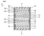
- FIG. 1A is a schematic cross-sectional view of a solid-state battery schematically showing a solid-state battery according to an embodiment of the present invention.
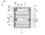
- FIG. 1B is a schematic cross-sectional view of a solid-state battery schematically showing a solid-state battery according to another embodiment of the present invention.
- FIG. 2 is a schematic cross-sectional view of the negative electrode layer for explaining the conductive path of the negative electrode layer in the solid-state battery of the present invention.
- FIG. 3A is a schematic cross-sectional view of the conductive auxiliary agent schematically showing an example of the conductive auxiliary agent having a long and narrow cross-sectional view contained in the negative electrode layer in the solid-state battery of the present invention.
- FIG. 1A is a schematic cross-sectional view of a solid-state battery schematically showing a solid-state battery according to an embodiment of the present invention.
- FIG. 1B is a schematic cross-sectional view of a solid-state battery schematically showing a solid-state battery according to
- FIG. 3B is a schematic cross-sectional view of the conductive auxiliary agent schematically showing another example of the conductive auxiliary agent having a long and narrow cross-sectional view contained in the negative electrode layer in the solid-state battery of the present invention.
- FIG. 4A is a schematic cross-sectional view of the solid-state battery manufactured in the examples according to the embodiment of the present invention, which schematically shows the solid-state battery (main surface current collecting structure).
- FIG. 4B is a schematic cross-sectional view of a solid-state battery schematically showing a solid-state battery (end face current collecting structure) according to another embodiment of the present invention manufactured in the examples.
- FIG. 5 is a schematic cross-sectional view of the negative electrode layer for explaining the conductive path of the negative electrode layer in the solid-state battery of the prior art.
- Solid-state battery refers to a battery in which its components (particularly the electrolyte layer) are composed of solids in a broad sense, and in a narrow sense, the components (particularly all components) are composed of solids. Refers to the "all-solid-state battery” that is configured.
- the “solid-state battery” as used herein includes a so-called “secondary battery” capable of repeating charging and discharging, and a “primary battery” capable of only discharging.
- the “solid-state battery” is preferably a "secondary battery”.
- the “secondary battery” is not overly bound by its name and may include, for example, a "storage device”.
- the solid-state battery of the present invention includes a positive electrode layer 1, a negative electrode layer 2, and a solid electrolyte layer 3, and usually, the positive electrode layer and the negative electrode layer are laminated via the solid electrolyte layer. It has a laminated structure.
- the positive electrode layer and the negative electrode layer may be laminated in two or more layers as long as a solid electrolyte layer is provided between them.
- the solid electrolyte layer is in contact with the positive electrode layer and the negative electrode layer and is sandwiched between them.
- the positive electrode layer and the solid electrolyte layer may be integrally sintered with each other, and / or the negative electrode layer and the solid electrolyte layer may be integrally sintered with each other.
- integral sintering of sintered bodies means that two or more members (particularly layers) adjacent to or in contact with each other are joined by sintering.
- the two or more members (particularly the layer) may be integrally sintered while being a sintered body.
- 1A and 1B are schematic cross-sectional views of a solid-state battery schematically showing a solid-state battery according to an embodiment of the present invention.
- the solid-state battery of the present invention includes a positive electrode current collector layer 11, a negative electrode current collector layer 21, a positive electrode current collector (not shown), a negative electrode current collector 22, and an electrode separation unit 15, 25, a protective layer 5, and end face electrodes 10 and 20 may be further provided.
- the solid-state battery of FIG. 1B is similar to the solid-state battery of FIG. 1A except that the negative electrode layer 2 has an end face current collecting structure.
- the end face current collecting structure of the negative electrode layer 2 of FIG. 1B is a negative electrode terminal via the negative electrode current collecting section 22 while being in contact with the negative electrode current collecting section 22 at the end face of the negative electrode layer 2. It is a structure that is electrically connected to 20.
- the negative electrode layer 2 has a main surface current collecting structure.
- the main surface current collecting structure of the negative electrode layer 2 of FIG. 1A is mainly via the negative electrode current collecting layer 21 while being in contact with the negative electrode current collecting layer 21 on the main surface of the negative electrode layer 2. It is a structure that is electrically connected to the negative electrode terminal 20.
- the negative electrode layer 2 contains a conductive auxiliary agent and a negative electrode active material, and may further contain a solid electrolyte.
- the conductive auxiliary agent, the negative electrode active material, and the solid electrolyte all preferably have the form of a sintered body.
- the negative electrode layer contains a conductive auxiliary agent, a negative electrode active material and a solid electrolyte
- the negative electrode layer is bonded between the negative electrode active material particles by the conductive auxiliary agent and the solid electrolyte, and the conductive auxiliary agent, the negative electrode active material particles and the solid.
- the electrolyte preferably has the form of a sintered body, which is bonded to each other by sintering.
- the negative electrode layer contains a conductive auxiliary agent having an elongated cross-sectional view as a conductive auxiliary agent in an area ratio of 7% or more and 28% or less with respect to the negative electrode layer, and is preferable from the viewpoint of further improving the utilization rate of the negative electrode active material.
- the content is 7.5% or more and 25% or less, more preferably 10% or more and 23% or less, and further preferably 15% or more and 22% or less.
- the negative electrode layer 2 contains the conductive auxiliary agent 200 having an elongated cross-sectional view, so that the conductive path p can be efficiently formed.
- FIG. 2 is a schematic cross-sectional view of the negative electrode layer for explaining the conductive path of the negative electrode layer in the solid-state battery of the present invention.
- the content of the conductive auxiliary agent having an elongated cross-sectional view with respect to the total conductive auxiliary agent is not particularly limited, and is usually 35% or more (particularly 35% or more and 100% or less) in terms of the area ratio to the total conductive auxiliary agent. From the viewpoint of further improving the utilization rate of the negative electrode active material, it is preferably 50% or more and 95% or less, and more preferably 70% or more and 90% or less.
- the content of the conductive auxiliary agent in the elongated cross-sectional shape is the value of the area ratio of the conductive auxiliary agent in the elongated shape in the cross-sectional view.
- the content of the conductive auxiliary agent having an elongated cross-sectional shape is the area of the conductive auxiliary agent having an elongated cross-sectional shape confirmed in the negative electrode layer of the SEM image (photograph) showing the laminated structure (cross-sectional structure) of the solid-state battery. It is a ratio value.
- the content of the conductive auxiliary agent having an elongated cross-sectional view is an average value of values measured at any 10 points, and is an area ratio to the negative electrode layer (that is, the total area of each visual field in the negative electrode layer) or It is expressed as the area ratio of the conductive auxiliary agent having an elongated cross-sectional view to the total conductive auxiliary agent (that is, the area of the total conductive auxiliary agent in each visual field).
- a conductive auxiliary agent having an elongated shape in cross-sectional view means a conductive auxiliary agent having an elongated shape in cross-sectional view of the negative electrode layer.
- a conductive auxiliary agent having an elongated shape in a cross-sectional view has a shape having a long direction in a cross-sectional view of the negative electrode layer.
- the "cross-sectional view" referred to in the present specification is a form when viewed from a direction substantially perpendicular to the thickness direction based on the stacking direction of each layer constituting the solid-state battery (in short, a surface parallel to the thickness direction). It is based on the form when cut out in) and includes a cross-sectional view.
- the "cross-sectional view” may be based on a surface parallel to the thickness direction based on the stacking direction of each layer constituting the solid-state battery, and may be based on a form cut out on a surface perpendicular to the positive electrode terminal and the negative electrode terminal.
- a cross-sectional view as shown in FIGS. 1A and 1B can be mentioned. Therefore, the "SEM image showing the laminated structure (cross-sectional structure) of the solid-state battery" used for various measurements may be an image based on the cross-sectional view as described above.
- the conductive auxiliary agent capable of having an elongated shape in cross section
- a flat conductive auxiliary agent, a fibrous conductive auxiliary agent, or a mixture thereof is used as the conductive auxiliary agent.
- a simple metal powder is used as the conductive auxiliary agent
- it is difficult to obtain a sufficient utilization rate of the negative electrode active material because the metal powder is beaded (particularly spherical) in the negative electrode layer at the time of sintering.
- a flat or fibrous conductive auxiliary agent is used as the conductive auxiliary agent, spheroidization (particularly spherical formation) is suppressed during sintering, and the conductive auxiliary agent has an elongated cross-sectional view after sintering.
- the conductive auxiliary agent having an elongated cross-sectional view corresponds to a flat conductive auxiliary agent, a fibrous conductive auxiliary agent, or a mixture thereof by disassembling the solid-state battery.
- the flat shape is a shape in which particles are crushed, and is also called a "scale shape” or a "flat shape”.
- the fibrous shape includes a "linear" shape or a "rod shape", and may be, for example, a shape possessed by so-called metal nanowires.
- the conductive auxiliary agent Even when only a simple metal powder (for example, a spherical conductive auxiliary agent) is used as the conductive auxiliary agent, some of the metal powders are bonded to each other by sintering in the negative electrode layer so as to have an elongated shape in cross section. May become.
- the negative electrode layer contains only metal powder in a proportion of 28% or less with respect to the negative electrode layer
- the content of the conductive auxiliary agent having an elongated cross-sectional view is usually 4% or less (or total conductivity) with respect to the negative electrode layer.
- the area ratio to the auxiliary agent is 10% or less), and the above-mentioned conductive auxiliary agent content having an elongated cross-sectional view as in the present invention cannot be achieved.
- the conductive auxiliary agent having an elongated shape in cross-sectional view is specifically defined in the negative electrode layer by the longest dimension a and the short side length (thickness dimension) b for one conductive auxiliary agent 200a in cross-sectional view, as shown in FIG. 3A.
- the depth length c (that is, the dimension in the front-back direction on FIG. 3A) (not shown) is not particularly limited.
- the longest dimension a is a dimension that defines the maximum length in a cross-sectional view.
- the short side length b is a dimension that defines the maximum length (or maximum thickness) in the direction perpendicular to the longest dimension a direction in cross-sectional view.
- the short side length b usually satisfies a> b.
- the depth length c is a dimension that defines the maximum length in the direction perpendicular to the cross-sectional view, and usually satisfies c ⁇ 2b (particularly 2a ⁇ c ⁇ 2b) in the case of a flat shape and 2b> c in the case of a fibrous shape. (Especially 2b> c> 0.5b) is satisfied.
- the slender shape in cross-sectional view specifically refers to a shape having a / b of 2.0 or more (particularly 2.0 or more and 20.0 or less).
- FIG. 3A is a schematic cross-sectional view of the conductive auxiliary agent schematically showing an example of the conductive auxiliary agent having a long and narrow cross-sectional view contained in the negative electrode layer in the solid-state battery of the present invention.
- the slender shape in cross section includes a bent slender shape with a bent portion.
- the bent elongated shape has the longest dimension a and the short side length (longest dimension a) and the short side length (for one conductive auxiliary agent 200b in the negative electrode layer, while having one or more bent portions 201 in the negative electrode layer.
- the shape is defined by the thickness dimension) b, and the depth length c (that is, the dimension in the front and back directions on FIG. 3B) (not shown) is not particularly limited.
- the longest dimension a is a dimension that defines the maximum length in a cross-sectional view.
- the short side length b is a dimension that defines the maximum length (or maximum thickness) in the direction perpendicular to the longest dimension a direction in cross-sectional view.
- the depth length c is a dimension that defines the maximum length in a plan view perpendicular to a cross-sectional view.
- the a, b and c in the bent elongated shape (eg, FIG. 3B) and their relationships are similar to those in the simple cross-sectional elongated shape (eg, FIG. 3A).
- FIG. 3B is a schematic cross-sectional view of the conductive auxiliary agent schematically showing another example of the conductive auxiliary agent having a long and narrow cross-sectional view contained in the negative electrode layer in the solid-state battery of the present invention.
- the average aspect ratio (the longest dimension a / short side length b described above) is usually 2.0 or more (particularly 2.0 or more and 20.0 or less) for the conductive auxiliary agent having an elongated shape in the negative electrode layer. From the viewpoint of further improving the utilization rate of the active material, it is preferably 2.0 or more and 15.0 or less, more preferably 2.5 or more and 10.0 or less, and further preferably 3.0 or more and 8.0 or less.
- the average aspect ratio (a / b) of the elongated conductive auxiliary agent is any 100 cross-sectional views confirmed in the negative electrode layer of the SEM image (photograph) showing the laminated structure (cross-sectional structure) of the solid-state battery.
- the average value based on the elongated conductive auxiliary agent is used.
- the average short side length b of the conductive auxiliary agent having an elongated cross-sectional view in the negative electrode layer is not particularly limited, and is preferably 0.1 ⁇ m or more and 4.0 ⁇ m or less from the viewpoint of further improving the utilization rate of the negative electrode active material. It is preferably 0.2 ⁇ m or more and 2.0 ⁇ m or less, more preferably 0.3 ⁇ m or more and 1.5 ⁇ m or less, and particularly preferably 0.3 ⁇ m or more and 1.0 ⁇ m or less.
- the average short side length b of the conductive auxiliary agent having an elongated cross-sectional shape is any 100 elongated shapes confirmed in the negative electrode layer of the SEM image (photograph) showing the laminated structure (cross-sectional structure) of the solid-state battery.
- the average value based on the conductive auxiliary agent is used.
- the average depth length c of the conductive auxiliary agent having an elongated cross-sectional view in the negative electrode layer is not particularly limited, and may be, for example, 0.1 ⁇ m or more and 10.0 ⁇ m or less.
- the average depth length c of the conductive auxiliary agent having an elongated cross-sectional view in the negative electrode layer is usually 0.1 ⁇ m or more and 20 ⁇ m or less.
- the average depth length c of the conductive auxiliary agent having an elongated cross-sectional view in the negative electrode layer is usually 0.1 ⁇ m or more and 10.0 ⁇ m or less.
- the average depth length c of the elongated conductive auxiliary agent in the cross-sectional view is in the negative electrode layer of the three-dimensional image created from 100 SEM images taken at intervals of 0.1 ⁇ m showing the laminated structure (cross-sectional structure) of the solid-state battery.
- An average value based on any 100 conductive auxiliary agents having an elongated cross-sectional view confirmed in the above can be used.
- the conductive auxiliary agent having an orientation angle of 30 ° or less is preferably 20 in area ratio to the total conductive auxiliary agent from the viewpoint of further improving the utilization rate of the negative electrode active material. It is contained in% or more (particularly 20% or more and 100% or less), more preferably 50% or more and 90% or less, further preferably 55% or more and 75% or less, and most preferably 61% or more and 66% or less.
- the orientation angle of the elongated conductive auxiliary agent in cross-sectional view is the same when the solid-state battery is allowed to stand so that the stacking direction L of the positive electrode layer, the solid electrolyte layer, the negative electrode layer, etc. is perpendicular to the horizontal direction. It is the absolute value of the angle (particularly the smaller angle) formed by the longest dimension a direction and the horizontal direction of the conductive auxiliary agent. For example, assuming that the vertical direction of FIG. 3A is parallel to the stacking direction L, the orientation angle of the conductive auxiliary agent 200a having an elongated cross-sectional view is 0 °. Further, for example, assuming that the vertical direction of FIG.
- the orientation angle of the conductive auxiliary agent 200b having an elongated cross-sectional view is ⁇ .
- the conductive auxiliary agent used in the present invention has an elongated shape in cross-sectional view, and the negative electrode layer containing the conductive auxiliary agent having an elongated cross-sectional view has an ultrathin thickness described later.
- Most of the auxiliaries eg, 50% or more in area ratio, especially 60% or more usually have an orientation angle of 30 ° or less in the negative electrode layer.
- the orientation angle of the elongated conductive auxiliary agent in cross-sectional view uses the value confirmed in the negative electrode layer of the SEM image (photograph) showing the laminated structure (cross-sectional structure) of the solid-state battery.
- the content of the conductive auxiliary agent having an orientation angle of 30 ° or less in the negative electrode layer with respect to the total conductive auxiliary agent is the SEM image (photograph) showing the laminated structure (cross-sectional structure) of the solid-state battery. It is a value of the area ratio of the conductive auxiliary agent having an elongated shape with an orientation angle of 30 ° or less, which is confirmed in the negative electrode layer, to the total conductive auxiliary agent. More specifically, the content of the conductive auxiliary agent having an elongated shape with an orientation angle of 30 ° or less is the average value of the values measured at any 10 points, and is the total conductive auxiliary agent (that is, the total conductivity in each visual field). It is expressed as the area ratio of the conductive auxiliary agent having an elongated cross-sectional view with an orientation angle of 30 ° or less with respect to the area of the auxiliary agent).
- the elongated conductive auxiliary agent in cross section is composed of a metal material.
- metal materials that can form a conductive auxiliary agent having an elongated shape in cross section include Ag (silver), Au (gold), Pd (palladium), Pt (platinum), Cu (copper), Sn (tin), and Ni ( Included is one or more metallic materials selected from the group consisting of nickel) and alloys thereof.
- the conductive auxiliary agent having an elongated cross-sectional view is preferably composed of silver from the viewpoint of further improving the utilization rate of the negative electrode active material.
- the negative electrode layer may further contain a conductive auxiliary agent other than the conductive auxiliary agent having an elongated cross-sectional view.
- a conductive auxiliary agent for example, spherical conductive auxiliary agents composed of the same metal material as the metal material constituting the above-mentioned conductive auxiliary agent having an elongated cross-sectional view, acetylene black, Ketjen black, Super P (registered trademark). ), Carbon materials such as carbon nanotubes such as VGCF (registered trademark), and the like.
- the total conductive auxiliary agent containing the conductive auxiliary agent having an elongated cross-sectional view and other conductive auxiliary agents is preferably 30% in the area ratio with respect to the negative electrode layer from the viewpoint of further improving the utilization rate of the negative electrode active material. It is contained below (particularly 5% or more and 30% or less), more preferably 12% or more and 30% or less, and further preferably 18% or more and 28% or less.
- the value of the area ratio of the total conductive auxiliary agent is used.
- the content of the total conductive auxiliary agent is a value of the area ratio of the total conductive auxiliary agent confirmed in the negative electrode layer of the SEM image (photograph) showing the laminated structure (cross-sectional structure) of the solid-state battery.
- the content of the total conductive auxiliary agent is an average value of the values measured at any 10 points, and is the ratio of the area of the total conductive auxiliary agent to the total area of each visual field in the negative electrode layer.
- the negative electrode layer is a layer that can occlude and release metal ions, and is preferably a layer that can occlude and release lithium ions.
- the negative electrode active material contained in the negative electrode layer is not particularly limited, and the molar ratio of Li (lithium) to V (vanadium) is 2.0 or more (from the viewpoint of further improving the utilization rate of the negative electrode active material and improving the discharge capacity). In particular, it is preferable to contain a negative electrode active material of 2 or more and 10 or less).
- the molar ratio of Li to V in the negative electrode active material is preferably 2 or more and 6 or less (particularly 2 or more and 4 or less) from the viewpoint of further improving the utilization rate of the negative electrode active material.
- the negative electrode layer contains a negative electrode active material having such a molar ratio.
- the spheroidization for example, spheroidization
- the conductive path p' is particularly likely to break, and the utilization rate of the negative electrode active material is further lowered.
- the negative electrode layer contains such a negative electrode active material, the breakage of the conductive path can be sufficiently suppressed, and as a result, the negative electrode at the time of charging and discharging with a smaller amount of the conductive auxiliary agent.
- the utilization rate of active materials can be improved more sufficiently. Therefore, when the negative electrode layer contains the negative electrode active material having the above molar ratio, the effect of forming the conductive auxiliary agent in a slender cross-sectional view is particularly high in the present invention.
- the solid electrolyte layer contains a solid electrolyte having a LISION type structure, as described later, the solid is solid.
- the LISION type solid electrolyte of the electrolyte layer contains V, even better bondability can be obtained between the solid electrolyte layer and the negative electrode layer.
- the side reaction at the time of co-stituting between the negative electrode active material contained in the negative electrode layer and the LISION type solid electrolyte in the solid electrolyte layer is suppressed, and the reversible capacity of the solid state battery can be increased. As a result, the utilization rate of the negative electrode active material at the time of charging / discharging can be sufficiently increased.
- the negative electrode active material is described by the general formula (1): from the viewpoint of further improving the utilization rate of the negative electrode active material. It is preferable to have an average chemical composition represented by. With such a composition, the reactivity of the solid electrolyte layer with the LISION type solid electrolyte can be further sufficiently reduced.
- the negative electrode active material used in the present invention further fully expresses its capacity by the redox of V. Therefore, in order to obtain a sufficient reversible capacity, the V amount y is preferably 0.5 ⁇ y ⁇ 1.0 as described later.
- A is one or more elements selected from the group consisting of Na (sodium), K (potassium), Mg (magnesium), Ca (calcium), and Zn (zinc).
- B is Zn (zinc), Al (aluminum), Ga (gallium), Si (silicon), Ge (germanium), Sn (tin), P (phosphorus), As (arsenic), Ti (tungsten), Mo ( One or more elements selected from the group consisting of molybdenum), W (tungsten), Fe (iron), Cr (chromium), and Co (cobalt).
- x has a relationship of 0 ⁇ x ⁇ 1.0, preferably a relationship of 0 ⁇ x ⁇ 0.5, and more preferably a relationship of 0 ⁇ x ⁇ 0.1.
- y has a relationship of 0.5 ⁇ y ⁇ 1.0, preferably a relationship of 0.55 ⁇ y ⁇ 1.0, and more preferably 1.
- a is the average valence of A.
- the average valence of A is (n1 ⁇ ) when, for example, n1 elements X having a valence a +, n2 elements Y having a valence b +, and n3 elements Z having a valence c + are recognized as A.
- b is the average valence of B.
- the average valence of B is, as B, for example, when n1 elements X having a valence a +, n2 elements Y having a valence b +, and n3 elements Z having a valence c + are recognized, the above-mentioned A It is the same value as the average valence of.
- A is one or more elements selected from the group consisting of Al and Zn.
- B is one or more, particularly two, elements selected from the group consisting of Si and P.
- x has a relationship of 0 ⁇ x ⁇ 0.06, and is more preferably 0.
- y has a relationship of 0.55 ⁇ y ⁇ 1.0, more preferably 0.8 ⁇ y ⁇ 1.0, and even more preferably 1.
- a is the average valence of A.
- b is the average valence of B.
- the negative electrode active material include, for example, Li 3 VO 4 , Li 3.2 (V 0.8 Si 0.2 ) O 4 , (Li 3.1 Al 0.03 ) (V 0.8 Si). 0.2 ) O 4 , (Li 3.1 Zn 0.05 ) (V 0.8 Si 0.2 ) O 4 , Li 3.3 (V 0.6 P 0.1 Si 0.3 ) O 4 , Li 3.18 (V 0.77 P 0.05 Si 0.18 ) O 4 , Li 3.07 (V 0.90 P 0.03 Si 0.07 ) O 4 , Li 3.22 (V 0) .72 P 0.06 Si 0.22 ) O 4 and the like.
- the chemical composition of the negative electrode active material may be an average chemical composition.
- the average chemical composition of the negative electrode active material means the average value of the chemical composition of the negative electrode active material in the thickness direction of the negative electrode layer.
- the average chemical composition of the negative electrode active material is obtained by breaking the solid-state battery and performing composition analysis with EDX using SEM-EDX (energy dispersive X-ray spectroscopy) from the viewpoint that the entire thickness direction of the negative electrode layer fits. It can be analyzed and measured.
- the average chemical composition of the negative electrode active material and the average chemical composition of the solid electrolyte described later can be automatically distinguished and measured according to their compositions in the above composition analysis.
- the negative electrode active material can be produced, for example, by the following method. First, a raw material compound containing a predetermined metal atom is weighed so that the chemical composition has a predetermined chemical composition, and water is added and mixed to obtain a slurry. The slurry can be dried, calcined at 700 ° C. or higher and 1000 ° C. or lower for 4 hours or more and 6 hours or less, and pulverized to obtain a negative electrode active material.
- the chemical composition of the negative electrode active material reflects the chemical composition of the negative electrode active material used at the time of production as it is when high-speed sintering is performed at 750 ° C. for about 1 minute together with the solid electrolyte layer, but the chemical composition is 750 ° C.
- sintering is performed for a long time of about 1 hour, element diffusion into the solid electrolyte layer proceeds, and the amount of V is usually reduced.
- the negative electrode active material preferably has a ⁇ II- Li 3 VO 4 type structure or a ⁇ II- Li 3 VO 4 type structure from the viewpoint of further improving the utilization rate of the negative electrode active material.
- a crystal structure By having such a crystal structure, the reversibility of charge and discharge is improved, and stable cycle characteristics can be obtained. Further, when the active material has a ⁇ II ⁇ Li 3 VO 4 type structure, the bondability with the LISION type solid electrolyte in the solid electrolyte layer is improved, which is more preferable.
- the negative electrode active material has a ⁇ II- Li 3 VO 4 type structure
- the negative electrode active material has a ⁇ II- Li 3 VO 4 type crystal structure
- the negative electrode active material has a ⁇ II- Li 3 VO 4 type structure, which means that the negative electrode active material (particularly its particles) has a so-called ⁇ II- Li 3 VO 4 type crystal structure in X-ray diffraction. It means that one or more major peaks corresponding to the Miller index peculiar to are shown at a predetermined angle of incidence.
- ICDD Card No. 01-073-6058 can be mentioned.
- the negative electrode active material has a ⁇ II- Li 3 VO 4 type structure
- the negative electrode active material has a ⁇ II- Li 3 VO 4 type crystal structure
- the negative electrode active material has a ⁇ II- Li 3 VO 4 type structure, which means that the negative electrode active material (particularly its particles) has a so-called ⁇ II- Li 3 VO 4 type crystal structure in X-ray diffraction.
- ICDD Card No. 01-073-2850 As an example of a negative electrode active material having a ⁇ II ⁇ Li 3 VO 4 type structure, for example, ICDD Card No. 01-073-2850 can be mentioned.
- the average chemical composition and crystal structure of the negative electrode active material in the negative electrode layer usually change due to element diffusion during sintering.
- the negative electrode active material preferably has the above-mentioned average chemical composition and crystal structure in a solid-state battery after being sintered together with the positive electrode layer and the solid electrolyte layer.
- the average particle size of the negative electrode active material is not particularly limited, and may be, for example, 0.01 ⁇ m or more and 20 ⁇ m or less, preferably 0.1 ⁇ m or more and 5 ⁇ m or less.
- the average particle size of the negative electrode active material for example, 10 or more and 100 or less particles can be randomly selected from the SEM image, and the average particle size (arithmetic mean) can be obtained by simply averaging the particles. can.
- the particle size is the diameter of the spherical particle assuming that the particle is perfectly spherical.
- a cross section of a solid-state battery is cut out, a cross-section SEM image is taken using SEM, and then image analysis software (for example, "A image-kun" (manufactured by Asahi Kasei Engineering Co., Ltd.)) is used to cut the particles.
- image analysis software for example, "A image-kun" (manufactured by Asahi Kasei Engineering Co., Ltd.)
- the particle diameter R can be obtained by the following formula.
- the average particle size of the negative electrode active material in the negative electrode layer can be automatically measured by specifying the negative electrode active material by the composition at the time of measuring the average chemical composition described above
- the volume ratio of the negative electrode active material in the negative electrode layer is not particularly limited, and is preferably 20% or more and 80% or less, and is preferably 30% or more and 75% or less, from the viewpoint of further improving the utilization rate of the negative electrode active material. More preferably, it is 30% or more and 60% or less.
- the volume ratio of the negative electrode active material in the negative electrode layer can be measured from the SEM image after the FIB cross-section processing. Specifically, the cross section of the negative electrode layer is observed using SEM-EDX. It is possible to measure the volume ratio of the negative electrode active material by determining that the portion where V is detected from EDX is the negative electrode active material and calculating the area ratio of the above portion.
- the particle shape of the negative electrode active material in the negative electrode layer is not particularly limited, and may be, for example, a spherical shape, a flat shape, or an indefinite shape.
- the negative electrode layer preferably further contains a solid electrolyte, particularly a solid electrolyte having a garnet-type structure. Since the negative electrode layer contains a garnet-type solid electrolyte, the ionic conductivity of the negative electrode layer can be increased, and a high rate can be expected. Further, since a side reaction at the time of co-firing with a negative electrode active material having a Li / V ratio of 2 or more can be suppressed, an improvement in the utilization rate of the negative electrode can be expected. As will be described later, it is preferable that the solid electrolyte layer also further contains a solid electrolyte, particularly a solid electrolyte having a garnet-type structure.
- the solid electrolyte layer contains a garnet-type solid electrolyte, so that the insulating property of the solid electrolyte layer can be improved. It is thought that this is because the garnet-type solid electrolyte is difficult to be reduced during charging and discharging, so it is difficult for electrons to be injected, and the degree of flexibility of the LISION-type solid electrolyte in the solid electrolyte increases, resulting in an increase in electron resistance. Be done. Further, since a side reaction at the time of co-firing with a negative electrode active material having a Li / V ratio of 2 or more can be suppressed, an improvement in the utilization rate of the negative electrode can be expected.
- At least one (particularly both) of the negative electrode layer or the solid electrolyte layer preferably contains a solid electrolyte having a garnet-type structure.
- one of the negative electrode layer and the solid electrolyte layer may contain a solid electrolyte having a garnet-type structure, or both of them are garnet. It means that it may contain a solid electrolyte having a mold structure.
- the solid electrolyte has a garnet-type structure
- a solid electrolyte having a garnet-type structure means that, in X-ray diffraction, the solid electrolyte incidents one or more major peaks corresponding to the Miller index inherent in the so-called garnet-type crystal structure. Means to show in angle.
- the solid electrolyte having a garnet-type structure is described by the general formula (2): It is preferable to have an average chemical composition represented by.
- the negative electrode layer contains a solid electrolyte having the above average chemical composition, further improvement in the utilization rate of the negative electrode active material can be achieved.
- A is one or more elements selected from the group consisting of Ga (gallium), Al (aluminum), Mg (magnesium), Zn (zinc), and Sc (scandium).
- B is one or more elements selected from the group consisting of Nb (niobium), Ta (tantalum), W (tungsten), Te (tellurium), Mo (molybdenum), and Bi (bismuth).
- x has a relationship of 0 ⁇ x ⁇ 0.5.
- y has a relationship of 0 ⁇ y ⁇ 2.0.
- a is the average valence of A, which is the same as the average valence of A in the formula (1).
- b is the average valence of B, which is the same as the average valence of B in the formula (1).
- A is one or more elements selected from the group consisting of Ga and Al.
- B is one or more elements selected from the group consisting of Nb, Ta, W, Mo, and Bi.
- x has a relationship of 0 ⁇ x ⁇ 0.3, preferably 0.
- y has a relationship of 0 ⁇ y ⁇ 1.0, preferably a relationship of 0 ⁇ y ⁇ 0.7, more preferably a relationship of 0.3 ⁇ y ⁇ 0.7, and is preferably 0.5.
- .. a is the average valence of A.
- b is the average valence of B.
- solid electrolyte represented by the general formula (2) examples include (Li 6.4 Ga 0.05 Al 0.15 ) La 3 Zr 2 O 12 and (Li 6.4 Ga 0.2 ) La. 3 Zr 2 O 12 , Li 6.4 La 3 (Zr 1.6 Ta 0.4 ) O 12 , (Li 6.4 Al 0.2 ) La 3 Zr 2 O 12 , Li 6.5 La 3 (Zr) Examples thereof include 1.5 Mo 0.25 ) O 12 and Li 6.5 La 3 (Zr 1.5 Ta 0.5 ) O 12.
- the average chemical composition of the solid electrolyte (particularly the solid electrolyte having a garnet-type structure) in the negative electrode layer means the average value of the chemical composition of the solid electrolyte in the thickness direction of the negative electrode layer.
- the average chemical composition of the solid electrolyte is analyzed by breaking the solid-state battery and performing composition analysis with EDX using SEM-EDX (energy dispersive X-ray spectroscopy) with a view that the entire thickness direction of the negative electrode layer fits. And measurable.
- the average chemical composition of the negative electrode active material and the average chemical composition of the solid electrolyte can be automatically distinguished and measured according to their compositions in the above composition analysis.
- the solid electrolyte of the negative electrode layer can be obtained by the same method as the negative electrode active material except that a raw material compound containing a predetermined metal atom is used, or can be obtained as a commercially available product.
- the average chemical composition and crystal structure of the solid electrolyte in the negative electrode layer usually change due to element diffusion during sintering.
- the solid electrolyte preferably has the above-mentioned average chemical composition and crystal structure in the solid-state battery after being sintered together with the positive electrode layer and the solid electrolyte layer.
- the volume ratio of the solid electrolyte (particularly the solid electrolyte having a garnet-type structure) in the negative electrode layer is not particularly limited, and is 10% from the viewpoint of the balance between further improving the utilization rate of the negative electrode active material and increasing the energy density of the solid battery. It is preferably 50% or more, and more preferably 20% or more and 40% or less.
- the volume ratio of the solid electrolyte in the negative electrode layer can be measured by the same method as the volume ratio of the negative electrode active material. Being a garnet-type solid electrolyte is based on the site where Zr and / or La is detected by EDX.
- the negative electrode layer may further contain, for example, a sintering aid, a conductive auxiliary agent, and the like, in addition to the negative electrode active material and the solid electrolyte.
- the negative electrode layer contains a sintering aid, it can be densified even during sintering at a lower temperature, and element diffusion at the negative electrode active material / solid electrolyte layer interface can be suppressed.
- a sintering aid known in the field of solid-state batteries can be used.
- the composition of the sintering aid contains at least Li (lithium), B (boron), and O (oxygen) with respect to B.
- the molar ratio of Li (Li / B) is preferably 2.0 or more.
- these sintering aids have low fusible properties, and by advancing liquid phase sintering, the negative electrode layer can be densified at a lower temperature. Further, by adopting the above composition, the side reaction between the sintering aid and the LISION type solid electrolyte used in the present invention at the time of co-sintering can be further suppressed.
- the sintering aid that satisfies these conditions include Li 3 BO 3 , (Li 2.7 Al 0.3 ) BO 3 , and Li 2.8 (B 0.8 C 0.2 ) O 3 . Of these, it is particularly preferable to use BO 3 having a particularly high ionic conductivity (Li 2.7 Al 0.3).
- the volume ratio of the sintering aid in the negative electrode layer is not particularly limited, and may be 0.1 or more and 10% or less from the viewpoint of further improving the utilization rate of the negative electrode active material and increasing the energy density of the solid-state battery. It is preferably 1% or more and 7% or less, more preferably.
- the volume ratio of the sintering aid in the negative electrode layer can be measured by the same method as the volume ratio of the negative electrode active material.
- B can be focused on as a detection element in EDX, which is determined to be in the region of the sintering aid.
- the porosity is not particularly limited, and is preferably 20% or less, more preferably 15% or less, still more preferably 10% or less, from the viewpoint of further improving and further reducing the utilization rate of the negative electrode active material.
- the porosity of the negative electrode layer the value measured from the SEM image after the FIB cross-section processing is used.
- the negative electrode layer usually has a thickness of 2 ⁇ m or more and 100 ⁇ m or less, preferably 2 ⁇ m or more and 50 ⁇ m or less.
- the negative electrode layer 2 may have an end face current collecting structure as shown in FIG. 1A, or may have a main surface current collecting structure as shown in FIG. 1B.
- the negative electrode layer preferably has an end face current collecting structure from the viewpoint of further improving the capacitance density (for example, energy density).
- the fact that the negative electrode layer 2 has an end face current collecting structure means that the negative electrode layer 2 has a structure that collects current on the end face 2a (particularly only the end face) of the negative electrode layer 2 on the negative electrode terminal 20 side.
- the negative electrode layer 2 is in contact with the negative electrode current collecting unit 22 at the end surface 2a (particularly only the end surface) of the negative electrode layer 2 on the negative electrode terminal 20 side, and the negative electrode current collecting unit 22 It may be electrically connected to the negative electrode terminal 20 via the negative electrode terminal 20, or is directly and electrically connected to the negative electrode terminal 20 on the negative electrode terminal 20 side at the end surface 2a (particularly only the end surface) of the negative electrode layer 2. May be. As shown in FIG.
- the negative electrode layer 2 collects negative electrode current from the negative electrode layer 2 at the end surface 2a (particularly only the end surface) on the negative electrode terminal 20 side from the viewpoint of ensuring sufficient electrical connection with the negative electrode terminal 20. It is preferable that the negative electrode terminal 20 is electrically connected to the negative electrode terminal 20 via the negative electrode current collecting unit 22 while being in contact with the unit 22.
- the negative electrode layer 2 and the negative electrode current collecting portion 22 are mutually end faces. As a result, they have a configuration in which they are adjacent to each other in the direction perpendicular to the stacking direction in the cross-sectional view.
- the negative electrode layer 2 and the negative electrode current collector 22 have a configuration in which they are adjacent to each other in the direction perpendicular to the stacking direction even in a plan view.
- the negative electrode current collecting unit 22 is usually in the stacking direction L in the negative electrode layer 2. It has an upper surface 2b and a flush upper surface 22b, and also has a flush lower surface 2c and a flush lower surface 22c in the stacking direction L in the negative electrode layer 2.
- Flip is a state in which there is no step between the two faces.
- the two surfaces are the upper surface 2b of the negative electrode layer 2 and the upper surface 22b of the negative electrode current collector 22, and the lower surface 2c of the negative electrode layer 2 and the lower surface 22c of the negative electrode current collector 22.
- the fact that the negative electrode layer 2 has a main surface current collecting structure means that the negative electrode layer 2 has a structure that collects current on the main surface of the negative electrode layer.
- the negative electrode layer 2 is electrically connected to the negative electrode terminal 20 via the negative electrode current collector layer 21 while being in contact with the negative electrode current collector layer 21 on the main surface 2x of the negative electrode layer 2.
- the negative electrode current collecting layer 21 may be laminated on the main surface of the negative electrode layer 2, and / or the negative electrode layer 2 is laminated on the main surface of the negative electrode current collecting layer 21. May be.
- the main surface is a surface having a relatively large area, and more specifically, an upper surface and / or a lower surface perpendicular to the stacking direction. Collecting electricity on the main surface means that electrons come and go mainly from the main surface.
- the negative electrode layer 2 is directly electrically connected to the negative electrode terminal 20 on the negative electrode terminal 20 side. May be electrically connected to.
- the negative electrode layer 2 may be laminated on both main surfaces of the negative electrode current collecting layer 21 as shown in FIG. 1A, or may be laminated on one main surface. May be done.
- the negative electrode current collector layer 21 and the negative electrode current collector 22 may further include a solid electrolyte.
- the negative electrode current collector layer 21 and the negative electrode current collector 22 are made of a sintered body containing at least a conductive material and a solid electrolyte.
- a material having a relatively large conductivity is usually used, and for example, a carbon material, silver, palladium, gold, platinum, aluminum, or copper. It is preferable to use at least one selected from the group consisting of and nickel.
- the solid electrolyte that may be contained in the negative electrode current collecting layer 21 and the negative electrode current collecting unit 22 may be selected from the same solid electrolytes as the solid electrolyte that may be contained in the negative electrode layer described above.
- the negative electrode current collecting layer 21 and the negative electrode current collecting unit 22 preferably have a sintered body form from the viewpoint of reducing the manufacturing cost of the solid-state battery and the internal resistance of the solid-state battery by the integral sintering.
- the negative electrode current collector layer 21 and the negative electrode current collector 22 have the form of a sintered body, for example, the negative electrode current collector layer 21 and the negative electrode current collector 22 are sintered assist in addition to the above-mentioned conductive material and solid electrolyte. It may be composed of a sintered body further containing an agent.
- the sintering aid contained in the negative electrode current collector layer 21 and the negative electrode current collector 22 may be selected from, for example, the same materials as the sintering aid that can be contained in the negative electrode layer.
- the thickness of the negative electrode current collector layer is not particularly limited, and may be, for example, 1 ⁇ m or more and 10 ⁇ m or less, preferably 1 ⁇ m or more and 5 ⁇ m or less, and particularly 1 ⁇ m or more and 3 ⁇ m or less.
- the thickness of the negative electrode current collector may usually be the same as that of the negative electrode layer.
- the negative electrode layer is a layer that can also be called a "negative electrode active material layer”.
- the negative electrode layer is preferably a layer capable of occluding and releasing lithium ions as described above, but the present invention does not prevent the negative electrode layer from being a layer capable of occluding and releasing sodium ions.
- the positive electrode layer 1 is not particularly limited.
- the positive electrode layer 1 contains a positive electrode active material.
- the positive electrode layer 1 preferably has the form of a sintered body containing positive electrode active material particles.
- the positive electrode layer is a layer that can occlude and release metal ions, and is preferably a layer that can occlude and release lithium ions.
- the positive electrode active material is not particularly limited, and a positive electrode active material known in the field of solid-state batteries can be used.
- Examples of the positive electrode active material include lithium-containing phosphoric acid compound particles having a pearcon-type structure, lithium-containing phosphoric acid compound particles having an olivine-type structure, lithium-containing layered oxide particles, and lithium-containing oxide particles having a spinel-type structure. Can be mentioned.
- Specific examples of the lithium-containing phosphoric acid compound having a Nashikon-type structure preferably used include Li 3 V 2 (PO 4 ) 3 .
- lithium-containing phosphate compound having preferably olivine structure used Li 3 Fe 2 (PO 4 ) 3, LiMnPO 4 , and the like.
- lithium-containing layered oxide particles preferably used include LiCoO 2 , LiCo 1/3 Ni 1/3 Mn 1/3 O2, and the like.
- Specific examples of the lithium-containing oxide having a spinel-type structure preferably used include LiMn 2 O 4 , LiNi 0.5 Mn 1.5 O 4 , Li 4 Ti 5 O 12. and the like.
- lithium-containing layered oxides such as LiCoO 2 , LiCo 1/3 Ni 1/3 Mn 1/3 O 2 and the like are used as positive electrode active materials. Is more preferably used. In addition, only one kind of these positive electrode active material particles may be used, or a plurality of kinds may be mixed and used.
- the positive electrode active material having a pear-con type structure in the positive electrode layer means that the positive electrode active material (particularly its particles) has a crystal structure that can be recognized as the crystal structure of the above. It means that one or more major peaks corresponding to the mirror index peculiar to the so-called Nashikon type crystal structure are shown at a predetermined incident angle. Examples of the positive electrode active material having a Nashikon type structure preferably used are exemplified above. Examples of the compound.
- the chemical composition of the positive electrode active material may be the average chemical composition.
- the average chemical composition of the positive electrode active material means the average value of the chemical composition of the positive electrode active material in the thickness direction of the positive electrode layer.
- the average chemical composition of the positive electrode active material is obtained by breaking the solid-state battery and performing composition analysis with EDX using SEM-EDX (energy dispersive X-ray spectroscopy) from the viewpoint that the entire thickness direction of the positive electrode layer fits. It can be analyzed and measured.
- the positive electrode active material can be obtained by the same method as the negative electrode active material except that a raw material compound containing a predetermined metal atom is used, or can be obtained as a commercially available product.
- the chemical composition and crystal structure of the positive electrode active material in the positive electrode layer usually change due to element diffusion during sintering.
- the positive electrode active material preferably has the above-mentioned chemical composition and crystal structure in a solid-state battery after being sintered together with the negative electrode layer and the solid electrolyte layer.
- the average particle size of the positive electrode active material is not particularly limited, and may be, for example, 0.01 ⁇ m or more and 10 ⁇ m or less, preferably 0.05 ⁇ m or more and 4 ⁇ m or less.
- the average particle size of the positive electrode active material can be obtained by the same method as the average particle size of the negative electrode active material in the negative electrode layer.
- the average particle size of the positive electrode active material in the positive electrode layer usually reflects the average particle size of the positive electrode active material used at the time of manufacture as it is. In particular, when LCO is used for the positive electrode particles, it is reflected as it is.
- the particle shape of the positive electrode active material in the positive electrode layer is not particularly limited, and may be, for example, a spherical shape, a flat shape, or an indefinite shape.
- the volume ratio of the positive electrode active material in the positive electrode layer is not particularly limited, and is preferably 30% or more and 90% or less, preferably 40% or more and 70% or less, from the viewpoint of further improving the utilization rate of the negative electrode active material. More preferred.
- the positive electrode layer may further contain, for example, a solid electrolyte, a sintering aid, a conductive auxiliary agent, and the like, in addition to the positive electrode active material.
- the type of solid electrolyte contained in the positive electrode layer is not particularly limited.
- Examples of the solid electrolyte contained in the positive electrode layer include solid electrolytes having a garnet-type structure (Li 6.4 Ga 0.2 ) La 3 Zr 2 O 12 and Li 6.4 La 3 (Zr 1.6 Ta 0.4).
- the solid electrolyte of the positive electrode layer can be obtained by the same method as the negative electrode active material except that a raw material compound containing a predetermined metal atom is used, or can be obtained as a commercially available product.
- the average chemical composition and crystal structure of the solid electrolyte in the positive electrode layer usually change due to element diffusion during sintering.
- the solid electrolyte preferably has the above-mentioned average chemical composition and crystal structure in the solid-state battery after being sintered together with the negative electrode layer and the solid electrolyte layer.
- the volume ratio of the solid electrolyte in the positive electrode layer is not particularly limited, and is preferably 20% or more and 60% or less from the viewpoint of further improving the utilization rate of the negative electrode active material and increasing the energy density of the solid state battery. More preferably, it is% or more and 45% or less.
- the same compound as the sintering aid in the negative electrode layer can be used.
- the volume ratio of the sintering aid in the positive electrode layer is not particularly limited, and should be 0.1% or more and 20% or less from the viewpoint of further improving the utilization rate of the negative electrode active material and increasing the energy density of the solid-state battery. Is preferable, and more preferably 1% or more and 10% or less.
- any conductive auxiliary agent known in the field of solid-state batteries can be used.
- conductive auxiliary agents include metal materials such as Ag (silver), Au (gold), Pd (palladium), Pt (platinum), Cu (copper), Sn (tin), and Ni (nickel); And carbon materials such as carbon nanotubes such as acetylene black, Ketjen black, Super P (registered trademark) and VGCF (registered trademark) can be mentioned.
- a conductive auxiliary agent having an elongated cross-sectional view in the negative electrode layer may be used.
- the volume ratio of the conductive auxiliary agent in the positive electrode layer is not particularly limited, and is preferably 10% or more and 50% or less from the viewpoint of further improving the utilization rate of the negative electrode active material and increasing the energy density of the solid-state battery. More preferably, it is 20% or more and 40% or less.
- the porosity is not particularly limited, and from the viewpoint of further improving the utilization rate of the negative electrode active material, it is preferably 20% or less, more preferably 15% or less, still more preferably 10% or less.
- porosity of the positive electrode layer a value measured by the same method as the porosity of the negative electrode layer is used.
- the positive electrode layer 1 may have a main surface current collecting structure as shown in FIGS. 1A and 1B, or may have an end surface current collecting structure.
- the positive electrode layer preferably has a main surface current collecting structure from the viewpoint of reducing the manufacturing cost.
- the fact that the positive electrode layer 1 has a main surface current collecting structure means that the positive electrode layer 1 has a structure that collects current on the main surface of the positive electrode layer.
- the positive electrode layer 1 is in contact with the positive electrode current collector layer 11 on the main surface 1x of the positive electrode layer 1 and is electrically connected to the positive electrode terminal 10 via the positive electrode current collector layer 11. Is connected.
- the positive electrode current collecting layer 11 may be laminated on the main surface of the positive electrode layer 1 and / or the positive electrode layer 1 is laminated on the main surface of the positive electrode current collecting layer 11. May be.
- the main surface is a surface having a relatively large area, and more specifically, an upper surface and / or a lower surface perpendicular to the stacking direction. Collecting electricity on the main surface means that electrons come and go mainly from the main surface.
- the positive electrode layer 1 is directly electrically connected to the positive electrode terminal 10 on the positive electrode terminal 10 side, but is interposed through the positive electrode current collector as in the positive electrode layer having an end face current collecting structure described later. It may be electrically connected to the positive electrode terminal 10.
- the positive electrode layer 1 may be laminated on both main surfaces of the positive electrode current collecting layer 11 or one main surface as shown in FIGS. 1A and 1B. It may be laminated on the surface.
- the fact that the positive electrode layer 1 has an end face current collecting structure means that the positive electrode layer 1 has a structure that collects current on the end face (particularly only the end face) of the positive electrode layer 1 on the positive electrode terminal 10 side.
- the positive electrode layer 1 is electrically connected to the positive electrode terminal 10 via the positive electrode current collector while being in contact with the positive electrode current collector at the end face (particularly only the end face) of the positive electrode layer 1 on the positive electrode terminal 10 side. It may be directly and electrically connected to the positive electrode terminal 10 at the end face (particularly only the end face) of the positive electrode layer 1 on the positive electrode terminal 10 side.
- the positive electrode current collector layer 11 and the positive electrode current collector that the positive electrode layer 1 can have include at least a conductive material.
- the positive electrode current collector layer 11 and the positive electrode current collector may further contain a solid electrolyte.
- the positive electrode current collector layer 11 and the positive electrode current collector are made of a sintered body containing at least a conductive material and a solid electrolyte.
- a material having a relatively large conductivity is usually used.
- a conductive material similar to the negative electrode current collector layer and the negative electrode current collector. May be selected from.
- the solid electrolyte that may be contained in the positive electrode current collecting layer 11 and the positive electrode current collecting portion may be selected from the same solid electrolytes as the solid electrolyte that may be contained in the negative electrode layer described above.
- the positive electrode current collecting layer 11 and the positive electrode current collecting portion preferably have a sintered body form from the viewpoint of reducing the manufacturing cost of the solid-state battery and the internal resistance of the solid-state battery by the integral sintering.
- the positive electrode current collector layer 11 and the positive electrode current collector have the form of a sintered body
- the positive electrode current collector layer 11 and the positive electrode current collector include a sintering aid in addition to the above-mentioned conductive material and solid electrolyte. It may be further composed of a sintered body containing the same.
- the sintering aid contained in the positive electrode current collector layer 11 and the positive electrode current collector may be selected from, for example, the same materials as the sintering aid that can be contained in the negative electrode layer.
- the thickness of the positive electrode current collector layer is not particularly limited, and may be, for example, 1 ⁇ m or more and 5 ⁇ m or less, particularly 1 ⁇ m or more and 3 ⁇ m or less.
- the thickness of the positive electrode current collector may usually be the same as that of the positive electrode layer.
- the positive electrode layer is a layer that can be called a "positive electrode active material layer”.
- the positive electrode layer is preferably a layer capable of occluding and releasing lithium ions as described above, but the present invention does not prevent the positive electrode layer from being a layer capable of occluding and releasing sodium ions.
- the solid electrolyte layer 3 is not particularly limited.
- the solid electrolyte layer 3 has a LISION type structure and contains at least a V-containing solid electrolyte (hereinafter, may be referred to as “first solid electrolyte”) from the viewpoint of further improving the utilization rate of the negative electrode active material. Is preferable.
- the solid electrolyte layer preferably has the form of a sintered body containing the first solid electrolyte.
- LISICON structure having the first solid electrolyte in the solid electrolyte layer, beta I structure, beta II type structure, beta II 'structure, T I type structure, T II type structure, gamma II type structure, and gamma 0 type structure
- the solid electrolyte layer is beta I structure, beta II type structure, beta II 'structure, T I type structure, T II type structure, gamma II type structure, gamma 0 type structure or one or more with these composite structures It may contain the solid electrolyte of.
- the LISION type structure of the first solid electrolyte is preferably a ⁇ II type structure from the viewpoint of further improving the utilization rate of the negative electrode active material.
- the first solid electrolyte in the electrolyte layer has a gamma II type structure, a sense that the solid electrolyte has a gamma II-type crystal structure, in a broad sense, those skilled in the art by gamma II type field of solid-state battery It means having a crystal structure that can be recognized as the crystal structure of.
- the fact that the first solid electrolyte has a ⁇ II type structure in the solid electrolyte layer means that the solid electrolyte has a Miller index peculiar to the so-called ⁇ II- Li 3 VO 4 type crystal structure in X-ray diffraction. It means that one or more major peaks corresponding to each other are shown at a predetermined angle of incidence.
- the fact that the first solid electrolyte has a ⁇ I type structure in the solid electrolyte layer means that the solid electrolyte has a ⁇ I type crystal structure, and in a broad sense, it is ⁇ I type by a person skilled in the art of solid batteries. It means having a crystal structure that can be recognized as the crystal structure of.
- the fact that the first solid electrolyte has a ⁇ I type structure in the solid electrolyte layer means that the solid electrolyte has a Miller index peculiar to the so-called ⁇ I- Li 3 VO 4 type crystal structure in X-ray diffraction. It means that one or more major peaks corresponding to each other are shown at a predetermined angle of incidence.
- the fact that the first solid electrolyte has a ⁇ II type structure in the solid electrolyte layer means that the solid electrolyte has a ⁇ II type crystal structure, and in a broad sense, ⁇ II type by a person skilled in the art of solid batteries. It means having a crystal structure that can be recognized as the crystal structure of. In a narrow sense, the fact that the first solid electrolyte has a ⁇ II type structure in the solid electrolyte layer means that the solid electrolyte has a Miller index peculiar to the so-called ⁇ II- Li 3 VO 4 type crystal structure in X-ray diffraction. It means that one or more major peaks corresponding to each other are shown at a predetermined angle of incidence.
- the solid electrolyte, the X-ray diffraction, the so-called beta II' is the first solid electrolyte beta II solid electrolyte layer -Li 3 VO 4 -type crystal structure specific mirror It means that one or more major peaks corresponding to the exponent are shown at a predetermined angle of incidence.
- J.solid state chem ARWest et.al, J.solid state chem. , 4,20-28 (1972)
- XRD data mirror index corresponding to the surface spacing d value
- the first solid electrolyte having a T I type structure solid electrolyte layer and means that the solid electrolyte has a T I type crystal structure, in a broad sense, T I-type by those skilled in the art of solid-state battery It means having a crystal structure that can be recognized as the crystal structure of. In a narrow sense, in The first solid electrolyte having a T I type structure solid electrolyte layer, the solid electrolyte, the X-ray diffraction, the Miller index inherent to the so-called T I -Li 3 VO 4 type crystal structure It means that one or more major peaks corresponding to each other are shown at a predetermined angle of incidence. Compounds having T I type structure (i.e.
- J.solid state chem ARWest et.al, J.solid state chem. , 4,20-28 (1972)
- ICDD Card No. 00-024-0668 a solid electrolyte
- the fact that the first solid electrolyte has a T II type structure means that the solid electrolyte has a T II type crystal structure, and in a broad sense, it is a T II type by a person skilled in the field of solid batteries. It means having a crystal structure that can be recognized as the crystal structure of. In a narrow sense, the fact that the first solid electrolyte has a T II type structure in the solid electrolyte layer means that the solid electrolyte has a Miller index peculiar to the so-called T II- Li 3 VO 4 type crystal structure in X-ray diffraction. It means that one or more major peaks corresponding to each other are shown at a predetermined angle of incidence.
- T type II structure ie, solid electrolytes
- J. solid state chem ARWest et.al, J. solid state chem., 4, 20-28 (1972)
- ICDD Card No. 00-024-0669 can be mentioned.
- the fact that the first solid electrolyte has a ⁇ 0 type structure in the solid electrolyte layer means that the solid electrolyte has a ⁇ 0 type crystal structure, and in a broad sense, it is ⁇ 0 type by a person skilled in the art of solid batteries. It means having a crystal structure that can be recognized as the crystal structure of.
- the fact that the first solid electrolyte has a ⁇ 0 type structure in the solid electrolyte layer means that the solid electrolyte has a Miller index peculiar to the so-called ⁇ 0- Li 3 VO 4 type crystal structure in X-ray diffraction. It means that one or more major peaks corresponding to each other are shown at a predetermined angle of incidence.
- the first solid electrolyte is represented by the general formula (3): It is more preferable to have an average chemical composition represented by.
- A is one or more elements selected from the group consisting of Na (sodium), K (potassium), Mg (magnesium), Ca (calcium), and Zn (zinc).
- B is Zn (zinc), Al (aluminum), Ga (gallium), Si (silicon), Ge (germanium), Sn (tin), P (phosphorus), As (arsenic), Ti (tungsten), Mo ( One or more elements selected from the group consisting of molybdenum), W (tungsten), Fe (iron), Cr (chromium), and Co (cobalt).
- x has a relationship of 0 ⁇ x 1.0, particularly 0 ⁇ x ⁇ 0.2.
- y has a relationship of 0 ⁇ y ⁇ 1.0, particularly 0.05 ⁇ y ⁇ 0.93, and is preferably 0.4 ⁇ y ⁇ 0. From the viewpoint of further improving the utilization rate of the negative electrode active material. 9. More preferably, it has a relationship of 0.6 ⁇ y ⁇ 0.9.
- a is the average valence of A, which is the same as the average valence of A in the formula (1).
- b is the average valence of B, which is the same as the average valence of B in the formula (1).
- the preferred embodiment is as follows: A is Al. B is one or more elements selected from the group consisting of Si, Ge, and P. x has a relationship of 0 ⁇ x ⁇ 0.2, particularly 0 ⁇ x ⁇ 0.1, and is preferably 0. y has a relationship of 0.7 ⁇ y ⁇ 0.9, and is preferably 0.8.
- the average chemical composition of the first solid electrolyte in the solid electrolyte layer means the average value of the chemical composition of the first solid electrolyte in the thickness direction of the solid electrolyte layer.
- the solid battery is broken, and SEM-EDX (energy dispersive X-ray spectroscopy) is used to analyze the composition by EDX from the viewpoint that the entire thickness direction of the solid electrolyte layer is contained. It can be analyzed and measured.
- the average chemical composition of the first solid electrolyte having a LISION type structure and the average chemical composition of the solid electrolyte having a garnet type structure described later can be automatically distinguished and measured according to their compositions in the above composition analysis. ..
- the site of the first solid electrolyte that is, the solid electrolyte of the LISION type structure
- the site of the second solid electrolyte is La, Zr.
- the first solid electrolyte of the solid electrolyte layer can be obtained by the same method as the negative electrode active material except that a raw material compound containing a predetermined metal atom is used, or can be obtained as a commercially available product.
- the chemical composition and crystal structure of the first solid electrolyte in the solid electrolyte layer usually change due to element diffusion during sintering.
- the first solid electrolyte preferably has the above-mentioned chemical composition and crystal structure in a solid-state battery after being sintered together with the negative electrode layer and the positive electrode layer.
- the chemical composition of the first solid electrolyte reflects the chemical composition of the solid electrolyte used at the time of production as it is when high-speed sintering is performed at 750 ° C. for about 1 minute together with the negative electrode layer.
- sintering is performed at ° C. for a long time of about 1 hour, element diffusion from the negative electrode active material of the negative electrode layer proceeds, and the amount of V usually increases.
- the volume ratio of the first solid electrolyte in the solid electrolyte layer is not particularly limited, and is preferably 10% or more and 80% or less, preferably 20% or more and 60% or more, from the viewpoint of further improving the utilization rate of the negative electrode active material. More preferably, it is more preferably 30% or more and 60% or less.
- the volume ratio of the first solid electrolyte in the solid electrolyte layer can be measured by the same method as the volume ratio of the positive electrode active material.
- the solid electrolyte layer preferably further contains a solid electrolyte having a garnet-type structure (hereinafter, may be simply referred to as "second solid electrolyte").
- second solid electrolyte a solid electrolyte having a garnet-type structure
- the insulating property of the solid electrolyte layer can be improved as described above. It is considered that this is because the second solid electrolyte is difficult to be reduced during charging and discharging, so that it is difficult for electrons to be injected, and the bending degree of the first solid electrolyte in the solid electrolyte is increased, so that the electron resistance is increased. Be done.
- the second solid electrolyte is the same as the solid electrolyte having a garnet-type structure that is preferably contained in the negative electrode layer, and may be selected from the same range as the solid electrolyte having a garnet-type structure described in the description of the negative electrode layer. good.
- the solid electrolyte layer and the negative electrode layer contain a solid electrolyte having a garnet-type structure
- the solid electrolyte having a garnet-type structure contained in the solid electrolyte layer and the solid electrolyte having a garnet-type structure contained in the negative electrode layer are They may have the same chemical composition, or they may have different chemical compositions from each other.
- a preferable solid electrolyte as the solid electrolyte layer B is a solid electrolyte having the following chemical composition in the above formula (2):
- A is one or more (particularly two) elements selected from the group consisting of Ga and Al.
- B is one or more elements selected from the group consisting of Nb, Ta, W, Mo, and Bi.
- x has a relationship of 0 ⁇ x ⁇ 0.3, and is preferably 0.2.
- y has a relationship of 0 ⁇ y ⁇ 1.0, preferably a relationship of 0 ⁇ y ⁇ 0.7, more preferably a relationship of 0 ⁇ y ⁇ 0.3, and further preferably 0.
- a is the average valence of A.
- b is the average valence of B.
- the average chemical composition of the second solid electrolyte in the solid electrolyte layer means the average value of the chemical composition of the second solid electrolyte in the thickness direction of the solid electrolyte layer.
- the solid battery is broken, and SEM-EDX (energy dispersive X-ray spectroscopy) is used to analyze the composition by EDX from the viewpoint that the entire thickness direction of the solid electrolyte layer is contained. It can be analyzed and measured.
- the volume ratio of the second solid electrolyte in the solid electrolyte layer is not particularly limited, and is preferably 10% or more and 80% or less, and 20% or more and 70% or less, from the viewpoint of further improving the utilization rate of the negative electrode active material. More preferably, it is more preferably 40% or more and 60% or less.
- the volume ratio of the second solid electrolyte in the solid electrolyte layer can be measured by the same method as the volume ratio of the positive electrode active material.
- the solid electrolyte layer may further contain, for example, a sintering aid, etc., in addition to the solid electrolyte. From the viewpoint of further improving the utilization rate of the negative electrode active material, it is preferable that at least one of the negative electrode layer and the solid electrolyte layer, preferably both, further contains a sintering aid. When at least one of the negative electrode layer or the solid electrolyte layer further contains a sintering aid, one of the negative electrode layer or the solid electrolyte layer may further contain a sintering aid, or both of them contain a sintering aid. It means that it may be further included.
- the same compound as the sintering aid in the negative electrode layer can be used.
- the volume ratio of the sintering aid in the solid electrolyte layer is not particularly limited, and is 0.1% or more and 20% or less from the viewpoint of further improving the utilization rate of the negative electrode active material and increasing the energy density of the solid battery. It is preferable, and it is more preferable that it is 1% or more and 10% or less.
- the thickness of the solid electrolyte layer is usually 0.1 ⁇ m or more and 200 ⁇ m or less, preferably 0.1 to 30 ⁇ m, and more preferably 20 to 1 ⁇ m from the viewpoint of thinning the solid electrolyte layer.
- the average value of the thickness measured at any 10 points in the SEM image is used.
- the porosity is not particularly limited, and is preferably 20% or less, more preferably 15% or less, still more preferably 10% or less, from the viewpoint of further improving the utilization rate of the negative electrode active material.
- porosity of the solid electrolyte layer a value measured by the same method as the porosity of the negative electrode layer is used.
- the chemical composition of the solid electrolyte layer does not necessarily have to be uniform in the solid electrolyte layer, and the chemical composition may change in the thickness direction, for example.
- the insulating property can be improved.
- the solid electrolyte layer is preferably a layer capable of conducting lithium ions as described above, but the present invention does not prevent the solid electrolyte layer from being a layer capable of conducting sodium ions.
- the protective layer 5 is formed on at least the upper and lower surfaces of the solid-state battery, and preferably is also formed on all the side surfaces of the solid-state battery.
- the protective layer 5 is for electrically, physically and chemically protecting a solid-state battery (particularly, a battery element such as a positive electrode layer, a negative electrode layer and a solid electrolyte layer).
- the protective layer 5 is usually made of an insulating material.
- An insulating substance means a substance that does not have ionic conductivity and electron conductivity. Therefore, the insulating substance is an inorganic substance that does not have ionic conductivity and electron conductivity.
- An inorganic substance having no ionic conductivity means an inorganic substance having an ionic conductivity of 1 ⁇ 10 -7 S / cm or less. From the viewpoint of suppressing deterioration of the battery in a longer period of time, the ionic conductivity is preferably 1 ⁇ 10 -10 S / cm or less.
- An inorganic substance having no electron conductivity means an inorganic substance having an electron conductivity of 1 ⁇ 10 -7 S / cm or less. From the viewpoint of suppressing deterioration of the battery in a longer period of time, the electron conductivity is preferably 1 ⁇ 10 -10 S / cm or less.
- the protective layer 5 When the protective layer 5 is composed of such an insulating substance, the protective layer 5 has excellent moisture resistance, environmental resistance and durability.
- the protective layer 5 can be a protective layer having higher bonding strength with the battery element as compared with the protective layer containing a resin (for example, a polymer compound).
- a resin for example, a polymer compound.
- the protective layer 5 can more sufficiently prevent the expansion and contraction of the solid-state battery as compared with the protective layer containing the polymer compound, and as a result, the deterioration of the battery performance can be more sufficiently suppressed.
- the insulating substance constituting the protective layer 5 is not particularly limited, and examples thereof include glass and ceramics.
- glass quartz glass (SiO 2 ) or at least one selected from SiO 2 and PbO, B 2 O 3 , MgO, ZnO, Bi 2 O 3 , Na 2 O, Al 2 O 3 is assembled. Examples thereof include combined composite oxide-based glass. Examples of ceramics include alumina, cordylite, mullite, steatite, and forsterite.
- the protective layer may be composed of one or more materials selected from the group consisting of these substances.
- the protective layer may contain a material having electron conductivity (for example, metal) as long as the battery element is not short-circuited.
- the content ratio of the electron conductive material may be, for example, 1% by volume or less. Since the protective layer contains an electron conductive material (for example, metal), the heat generated by the battery reaction can be smoothly released to the outside.
- the protective layer is composed of a sintered body containing the above-mentioned insulating substance particles.
- the sintered body constituting the protective layer has pores between the insulating substance particles, it can suppress the adsorption, absorption and permeation of water and gas (carbon dioxide) in the thickness direction (for example, the stacking direction L).
- the thickness direction for example, the stacking direction L.
- the protective layer may contain a resin such as a polymer compound, and for example, the polymer compound used at the time of production and / or a thermal decomposition product thereof may remain.
- the content of the polymer compound and the residue such as a thermal decomposition product thereof in the protective layer is usually 0.1% by weight or less, particularly 0.01% by weight or less, based on the total amount of the protective layer.
- residues are generated as in the protective layer. It may remain.
- the content of the residue in each layer or each part of the positive electrode layer, the positive electrode current collector layer, the positive electrode current collector, the negative electrode layer, the negative electrode current collector layer, the negative electrode current collector, the solid electrolyte layer and the electrode separation part is the total amount of each layer.
- the value may be within the same range as the residue content range in the protective layer.
- the porosity of the protective layer may be, for example, 0.1% by volume or more and 20% by volume or less, particularly 1% by volume or more and 10% by volume or less.
- the oxygen permeability of the protective layer in the thickness direction may be, for example, 10 -1 cc / m 2 / day / atmospheric pressure or less, particularly 10 -3 cc / m 2 / day / atmospheric pressure or less.
- the H 2 O permeability in the thickness direction of the protective layer may be, for example, 10-2 g / m 2 / day or less, particularly 10 -4 g / m 2 / day or less. H 2 O permeability it is used the carrier gas method, Chaku ⁇ , a value measured at 25 ° C. by Ca etching method.
- the protective layer may further contain, for example, a sintering aid in addition to the insulating substance.
- the protective layer preferably further contains a sintering aid.
- the sintering aid in the protective layer the same compound as the sintering aid in the negative electrode layer can be used.
- the thickness of the thickest portion of the protective layer is preferably 500 ⁇ m or less, more preferably 100 ⁇ m or less, still more preferably 50 ⁇ m or less, and most preferably 20 ⁇ m or less. ..
- the protective layer preferably has an average thickness of 1 ⁇ m or more, more preferably 5 ⁇ m or more, from the viewpoint of further suppressing deterioration of battery performance due to adsorption, absorption, permeation, etc. of water and gas (carbon dioxide). ..
- the maximum thickness and the average thickness for the thickness at any 100 points are used, respectively.
- the protective layer covers the upper and lower surfaces of the solid-state battery.
- the protective layer may be in direct contact with the upper and lower surfaces of the battery element covered by the protective layer, as shown in FIGS. 1A and 1B, or via a layer other than the layer constituting the battery element. May be indirectly contacted.
- the fact that the protective layer is in direct contact with the upper and lower surfaces of the battery element means that the surface of the protective layer and the battery element do not have layers other than the layers constituting the battery element intervening between the protective layer and the battery element. It means that it is in direct contact with the surface of the battery.
- the protective layer is integrally sintered between the upper and lower surfaces of the battery element covered by the protective layer and the sintered body.
- the fact that the protective layer is integrally sintered between the upper and lower surfaces of the battery element covered by the protective layer and the sintered body means that the protective layer is fired with the upper and lower surfaces of the battery element covered by the protective layer. It means that they are joined by firing.
- the protective layer and the upper and lower surfaces of the battery element covered by the protective layer are both sintered bodies, but are integrally sintered.
- the protective layer and the battery element preferably have an integrally sintered structure.
- the protective layer and the upper and lower surfaces of the battery element covered by the protective layer do not have to be strictly integrated, and a part of the protective layer may not be integrated.
- the protective layer and the upper and lower surfaces of the battery element covered by the protective layer may be integrated as a whole.
- the upper and lower surfaces of the battery element covered by the protective layer are usually the surface of the outermost layer of the battery element.
- the outermost layer of the battery element is the uppermost layer arranged at the highest level and the lowest layer arranged at the lowest level among the layers constituting the battery element.
- the surface of the outermost layer is the upper surface of the uppermost layer and the lower surface of the lowermost layer.
- the solid-state battery of the present invention usually further has electrode separation portions (also referred to as “margins” or “margins”) 15, 25.
- the electrode separating portion 15 (that is, the positive electrode separating portion) is arranged around the positive electrode layer 1 to separate the positive electrode layer 1 from the negative electrode terminal 20.
- the electrode separating portion 25 (that is, the negative electrode separating portion) is also arranged around the negative electrode layer 2 to separate the negative electrode layer 2 from the positive electrode terminal 10.
- the electrode separating portions 15 and 25 are preferably composed of one or more materials selected from the group consisting of, for example, a solid electrolyte, an insulating substance, and a mixture thereof.
- a solid electrolyte that can form the electrode separation portions 15 and 25 the same material as the solid electrolyte that can form the solid electrolyte layer can be used.
- the insulating substance that can form the electrode separating portions 15 and 25, the same material as the insulating substance that can form the protective layer can be used.
- the electrode separation portion further contains a sintering aid.
- a sintering aid in the electrode separation portion, the same compound as the sintering aid in the negative electrode layer can be used.
- the solid-state battery of the present invention has electrode terminals 10 and 20 electrically connected to a positive electrode layer or a negative electrode layer on each of the two opposing side surfaces.
- the electrode terminal electrically connected to the positive electrode layer is referred to as a positive electrode terminal
- the electrode terminal electrically connected to the negative electrode layer is referred to as a negative electrode terminal 20.
- the electrode terminal is a member also called an end face electrode.
- the solid-state battery of the present invention has electrode terminals 10 and 20 parallel to each other and parallel to the stacking direction L.
- the electrode terminal preferably contains a conductive material having a high conductivity.
- the specific material of the conductive material for forming the electrode terminal is not particularly limited, but from the viewpoint of conductivity, for example, gold, silver, copper, platinum, tin, palladium, aluminum, titanium. , Nickel, oxygen-free copper, Cu—Sn alloy, Cu—Zr alloy, Cu—Fe alloy, Cu—Cr—Sn—Zn alloy, 42 alloy (Ni—Fe alloy), Koval alloy) At least one type of conductive metal (ie, metal or alloy) can be mentioned.
- the thickness of the electrode terminals 10 and 20 is not particularly limited, and may be, for example, 1 ⁇ m or more and 1 mm or less, particularly 10 ⁇ m or more and 100 ⁇ m or less.
- the solid-state battery can be manufactured by, for example, a so-called green sheet method, a printing method, or a method combining these methods.
- a paste is prepared by appropriately mixing a solvent, a resin, or the like with the positive electrode active material.
- the paste is applied onto the sheet and dried to form a green sheet for forming the positive electrode layer.
- the green sheet for the positive electrode layer may contain a solid electrolyte, a conductive auxiliary agent and / or a sintering auxiliary agent and the like.
- a paste is prepared by appropriately mixing a conductive auxiliary agent, a solvent, a resin, etc. with the negative electrode active material.
- the paste is applied onto the sheet and dried to form a green sheet for forming the negative electrode layer.
- the green sheet for the negative electrode layer may contain a solid electrolyte and / or a sintering aid and the like.
- the paste is applied and dried to prepare a green sheet for forming a solid electrolyte layer.
- the green sheet for the solid electrolyte layer may contain a sintering aid or the like.
- the paste is prepared by appropriately mixing a solvent, resin, etc. with the insulating substance.
- the paste is applied and dried to prepare a green sheet for forming a protective layer.
- the green sheet for the protective layer may contain a sintering aid or the like.
- the paste is prepared by appropriately mixing a solvent, resin, etc. with the solid electrolyte and / or the insulating substance.
- the paste is applied and dried to prepare a green sheet for forming the electrode separation portion.
- the green sheet for the electrode separation portion may contain a sintering aid or the like.
- a laminated body is produced by appropriately laminating the green sheets obtained by the above method.
- the produced laminate may be pressed.
- a preferred pressing method includes a hydrostatic pressure pressing method and the like.
- the electrode terminal paste is applied to a predetermined arrangement in the laminated body, and the solid-state battery can be obtained by sintering at, for example, 600 to 800 ° C.
- the printing method will be described.
- the printing method is the same as the green sheet method except for the following items. -Prepare an ink for each layer having a composition similar to that of the paste for each layer for obtaining a green sheet, except that the amount of the solvent and the resin is suitable for use as an ink. -Print and laminate using the ink of each layer to prepare a laminate.
- garnet-type solid electrolyte powder solid electrolyte powder of the negative electrode layer and second solid electrolyte powder of the solid electrolyte layer
- the garnet-type solid electrolyte powder used in Examples and Comparative Examples was produced as follows.
- Raw materials include lithium hydroxide monohydrate LiOH ⁇ H 2 O, lanthanum hydroxide La (OH) 3 , zirconium oxide ZrO 2 , gallium oxide Ga 2 O 3 , aluminum oxide Al 2 O 3 , niobium oxide Nb 2 O 5 , Tantal oxide Ta 2 O 5 and molybdenum oxide MoO 3 were used.
- Each raw material was weighed so that the chemical composition had a predetermined chemical composition, water was added, the mixture was sealed in a 100 ml polyethylene polypot, and the pot was rotated at 150 rpm for 16 hours to mix the raw materials. Further, the lithium hydroxide monohydrate LiOH ⁇ H 2 O, which is the Li source, was charged in an excess of 3 wt% with respect to the target composition in consideration of Li deficiency during sintering. The obtained slurry was evaporated and dried, and then calcined at 900 ° C. for 5 hours to obtain a target phase. A mixed solvent of toluene-acetone was added to the obtained calcined powder, and the mixture was pulverized with a planetary ball mill for 6 hours. This pulverized powder was dried to obtain a solid electrolyte powder. It was confirmed by ICP measurement that the above powder had no composition deviation.
- Solid electrolyte powder was produced as follows.
- Raw materials include lithium hydroxide monohydrate LiOH ⁇ H 2 O, vanadium pentoxide V 2 O 5 , silicon oxide SiO 2 , germanium GeO 2 , phosphorus oxide P 2 O 5 , aluminum oxide Al 2 O 3 , zinc oxide. ZnO was used.
- Each raw material was appropriately weighed so that the chemical composition had a predetermined chemical composition, water was added, the mixture was sealed in a 100 ml polyethylene polypot, and the pot was rotated at 150 rpm for 16 hours to mix the raw materials. After the obtained slurry was evaporated and dried, it was calcined in air at 800 ° C. for 5 hours. Alcohol was added to the obtained calcined powder, and the mixture was resealed in a 100 ml polyethylene polypot and rotated at 150 rpm for 16 hours on the pot rack for pulverization. The pulverized powder was again baked at 900 ° C. for 5 hours.
- the sintering aid powder used in Examples and Comparative Examples was produced as follows. Lithium hydroxide monohydrate LiOH ⁇ H 2 O, boron oxide B2 O3, lithium carbonate Li 2 CO 3 and aluminum oxide Al 2 O 3 were used as raw materials. Each raw material was appropriately weighed so that the chemical composition had a predetermined chemical composition, mixed well in a mortar, and then calcined at 650 ° C. for 5 hours. Then, the calcined powder was crushed well in a mortar and mixed again, and then main-baked at 680 ° C. for 40 hours.
- a mixed solvent of toluene-acetone was added to the obtained main baking powder, pulverized with a planetary ball mill for 6 hours, and dried to obtain a sintering aid powder. It was confirmed by ICP measurement that the above powder had no composition deviation.
- the aspect (a / b) ratio of the obtained flat Ag powder B was 4.4, and b was 0.5 ⁇ m.
- the aspect (a / b) ratio of the obtained flat Ag powder C was 4.5, and b was 1.5 ⁇ m.
- the aspect (a / b) ratio of the obtained flat Ag powder D was 4.6, and b was 2.2 ⁇ m.
- the aspect (a / b) ratio of the obtained flat Ag powder E was 2.3, and b was 0.9 ⁇ m.
- the aspect (a / b) ratio of the obtained flat Ag powder F was 3.5, and b was 0.9 ⁇ m.
- the aspect (a / b) ratio of the obtained flat Ag powder G was 7.0, and b was 0.8 ⁇ m.
- the aspect (a / b) ratio of the obtained flat Ag powder H was 12.1 and b was 0.7 ⁇ m.
- Example 1 Manufacturing of solid-state batteries
- the solid-state battery (solid-state battery for unipolar evaluation) shown in FIG. 4A was manufactured by the following method. Since the following description regarding the solid-state battery manufacturing method in this example is cited in other examples / comparative examples, the methods and information in the other examples / comparative examples are also described in the following description. Has been done.
- Li 3 VO 4 as an anode active material ( ⁇ II -Li 3 VO 4 type), Li 6.5 La 3 (Zr 1.5 Ta 0.5) as a solid electrolyte powder O 12 (garnet ), Flat Ag powder A as a conductive auxiliary agent having an elongated shape in cross section, and Li 3 BO 3 as a sintering auxiliary agent were weighed and kneaded with butyral resin, alcohol, and a binder to prepare a slurry for a negative electrode layer.
- the slurry for the negative electrode layer was sheet-molded on a PET film using the doctor blade method, dried and peeled off to obtain a green sheet for the negative electrode layer.
- the green sheet for the negative electrode layer and the green sheet for the solid electrolyte layer were laminated on each other and pressure-bonded to obtain a laminated body.
- the laminate was cut into a square shape (planar view shape) having a top view dimension of 10 mm ⁇ 10 mm.
- an Ag paste coating layer for the negative electrode current collector layer 21 was formed on the surface of the green sheet for the negative electrode layer opposite to the green sheet for the solid electrolyte layer.
- the obtained laminate was sandwiched between two porous setters, the binder was removed at 400 ° C., and then sintering was performed at 750 ° C.
- firing was performed in a reducing atmosphere under N 2 / H 2 in order to suppress oxidation of the conductive additive or active material during firing.
- firing was performed in an Air atmosphere.
- a Li metal 50 was attached to the surface of the solid electrolyte layer opposite to the negative electrode layer as a counter electrode and a reference electrode, and WIP (Warm Isostatic Pressing) treatment was performed under the conditions of 60 ° C. and 200 MPa to manufacture a solid state battery. ..
- WIP Warm Isostatic Pressing
- the negative electrode layer 2 and the negative electrode current collector layer 21 were confirmed using a scanning electron microscope, they were 100 ⁇ m, 15 ⁇ m, and 5 ⁇ m, respectively.
- the porosity of the solid electrolyte layer and the negative electrode layer was 10% or less, and it was confirmed that the sintering had proceeded sufficiently.
- Such a solid-state battery has a main surface current collecting structure, and as shown in FIG. 4A, collects current from the electrode layer in the direction of the arrow.
- the electron diffusion path in the negative electrode layer 2 was 15 ⁇ m.
- the top view dimension (dimension in the X and Y directions) after sintering was measured, it was 8 mm ⁇ 8 mm.
- the solid-state battery of this example shrank as the voids decreased through the sintering process.
- the center of gravity of a solid-state battery in a plan view is a point when a material of the same quality (for example, paper) is cut out at the contour of the solid-state battery (plan view) and supported by points in a balanced manner.
- the area ratio of the total conductive auxiliary agent confirmed in the negative electrode layer of the SEM image was determined.
- the area ratio is an average value of values measured at arbitrary 10 points, and is the ratio of the area of the total conductive auxiliary agent to the total area of each visual field.
- the conductive auxiliary agent having an elongated shape in cross section confirmed in the negative electrode layer of the SEM image taken by the measuring method of the area ratio of all conductive auxiliary agents was obtained. ..
- the content of the conductive auxiliary agent having an elongated cross-sectional view is the average value of the values measured at any 10 points, and is the area allocation to the negative electrode layer (that is, the total area of each visual field in the negative electrode layer) and the total. It was determined as the area ratio of the conductive auxiliary agent having an elongated cross-sectional view to the conductive auxiliary agent (that is, the area of the total conductive auxiliary agent in each visual field).
- the area ratio of the elongated conductive auxiliary agent was determined.
- the area ratio is an average value of values measured at any 10 points, and is a ratio of the area of the conductive auxiliary agent having an elongated cross-sectional view with an orientation angle of 30 ° or less with respect to the area of the total conductive auxiliary agent in each visual field. ..
- the -Average aspect ratio (a / b) of the conductive auxiliary agent having an elongated cross-sectional view confirmed in the negative electrode layer of the SEM image taken by the method of measuring the area ratio of the total conductive auxiliary agent was determined.
- the aspect ratio is an average value of the aspect ratios of any 100 conductive auxiliary agents having a long and narrow cross-sectional view measured at any 10 points.
- the average short side length b of the conductive auxiliary agent having a long and narrow cross-sectional view confirmed in the negative electrode layer of the SEM image taken by the method of measuring the area ratio of the total conductive auxiliary agent was determined.
- the average short side length b is an average value of the short side lengths of any 100 conductive auxiliary agents having a long and narrow cross-sectional view measured at any 10 points.
- Utilization rate of negative electrode active material For solid-state batteries, the amount of electricity was measured in a voltage range of 0.2V to 3.0V (vs. Li / Li +) at a current density equivalent to 0.05C by a constant current charge / discharge test. The reversible capacity was calculated. The initial reversible capacity was calculated by dividing the initial reversible amount of electricity obtained from the constant current charge / discharge test by the weight of the negative electrode active material. Further, the utilization rate R was calculated by dividing the initial reversible capacity by the theoretical capacity, with the capacity when V (vanadium) in the negative electrode active material proceeded as a two-electron reaction as the theoretical capacity.
- Examples 2 to 4 A solid-state battery was manufactured, measured and evaluated by the same method as in Example 1 except that the content of the conductive auxiliary agent having an elongated cross-sectional shape was changed.
- Spherical conductive auxiliary agent (spherical Ag powder A, average primary particle size 0.4 ⁇ m, manufactured by Shoei Chemical Co., Ltd.) was used instead of the elongated conductive auxiliary agent in cross section, and the content of the spherical conductive auxiliary agent was changed.
- the solid-state battery was manufactured, measured and evaluated by the same method as in Example 1 except for the above.
- Comparative Examples 1 to 3 show the utilization rate of the active material of the solid-state battery in which the content of the spherical conductive auxiliary agent was changed. It was found that in the cell using the spherical conductive auxiliary agent, the utilization rate of the active material decreased remarkably as the area ratio of the conductive auxiliary agent decreased. It is considered that this is because the conductive path of the conductive auxiliary agent in the negative electrode layer is interrupted, so that electrons are not supplied and there is an active material that does not contribute to charging / discharging. On the other hand, from Examples 1 to 4, it was found that by containing the flat powder as the conductive auxiliary agent, the reversible capacity can be maintained at a high level even if the content of the conductive auxiliary agent is reduced.
- Examples 5 and 6 and Comparative Example 4 The same method as in Example 2 except that the spherical conductive auxiliary agent and the flat conductive auxiliary agent were mixed and used, and the area ratio of the flat conductive auxiliary agent was changed by changing the mixing ratio thereof. The solid-state battery was manufactured, measured and evaluated.
- Example 7 to 9 A solid-state battery was manufactured, measured and evaluated by the same method as in Example 2 except that the type of flat Ag powder was changed.
- the utilization rate of the active material increases as the thickness b of the short side of the flat conductive auxiliary agent decreases. It is considered that this is because, for the same aspect ratio, the smaller the short side b, the larger the contact area between the active material and the conductive auxiliary agent. This time, it was found that a higher utilization rate of the active material can be obtained by setting the value of b to 2.0 ⁇ m or less, particularly 1.5 ⁇ m or less.
- Example 10 to 13 A solid-state battery was manufactured, measured and evaluated by the same method as in Example 2 except that a flat conductive auxiliary agent having the same short side thickness and a different aspect ratio was used.
- Example 14 The negative electrode current collector was not formed, and the negative electrode layer was in contact with the negative electrode current collector at the end face of the negative electrode layer, and the end face current collector was electrically connected to the negative electrode terminal via the negative electrode current collector.
- the solid-state battery was manufactured, measured and evaluated by the same method as in Example 2 except that the structure was adopted.
- the obtained solid-state battery had a cross-sectional structure as shown in FIG. 4B.
- FIG. 4B the same method as the solid-state battery manufacturing method of FIG. 4A is used except that an Ag paste coating layer for the negative electrode current collecting portion 210 is formed on the end face of the green sheet for the negative electrode layer. ,
- the solid-state battery of FIG. 4B was manufactured.
- Such a solid-state battery has an end face current collecting structure, and as shown in FIG. 4B, collects current from the electrode layer in the direction of the arrow.
- the electron diffusion path in the negative electrode layer 2 was 15 ⁇ m.
- the top view dimension (dimension in the X and Y directions) after sintering was measured, it was 8 mm ⁇ 8 mm.
- the solid-state battery of this example shrank as the voids decreased through the sintering process.
- Example 15 to 18 A solid-state battery is manufactured by the same method as in Example 14 except that the area ratio of the flat conductive auxiliary agent having an orientation angle of 30 ° or less is changed by changing the slurry viscosity at the time of forming the green sheet for the negative electrode layer. , As well as measurements and evaluations.
- Spherical conductive auxiliary agent (spherical Ag powder A, average primary particle size 0.4 ⁇ m, manufactured by Shoei Chemical Co., Ltd.) was used instead of the elongated conductive auxiliary agent in cross section, and the content of the spherical conductive auxiliary agent was changed.
- the solid-state battery was manufactured, measured and evaluated by the same method as in Example 14 except that the solid-state battery was allowed to be produced.
- Comparative Example 5 Although the same negative electrode layer as in Comparative Example 1 was used, it was found that the utilization rate of the active material was significantly reduced by adopting the end face current collecting structure. It is considered that this is because in the end face current collecting structure, it is necessary to continuously form the conductive path also in the in-plane direction, so that the conductive path becomes very long and the conductive path is easily interrupted. On the other hand, in Example 14, although the same negative electrode layer as in Example 2 was used, it was found that the utilization rate was maintained at a high level even with the end face current collecting structure.
- the utilization rate of the active material changes by changing the proportion of the flat powder having an orientation angle of 30 ° or less.
- the proportion of the flat powder having an orientation angle of 30 ° or less was 55% or more and 75% or less
- the utilization rate of the active material was 90% or more, which was a preferable result. It is considered that this is because when the degree of orientation is low, it is difficult to obtain a conductive path in the in-plane direction, and when the degree of orientation is too high, it is difficult to form a conductive path in the thickness direction of the negative electrode layer.
- Example 19 A solid-state battery was manufactured, measured and evaluated by the same method as in Example 14 except that the fibrous Ag powder A was used as the conductive auxiliary agent having an elongated cross-sectional view. Even when the fibrous Ag powder was used, the same or better effect as the case where the flat powder of Example 14 was used was obtained.
- Example 20 A solid-state battery was manufactured, measured and evaluated by the same method as in Example 2 except that the flat Cu powder A was used as the conductive auxiliary agent having an elongated cross-sectional view. It was found that the same effect as Ag can be obtained when Cu is used as the conductive auxiliary agent.
- Example 21 A solid-state battery was manufactured, measured and evaluated by the same method as in Example 2 except that (Li1.1V0.9O2) was used as the negative electrode active material.
- Example 6 A solid by the same method as in Example 21 except that a spherical conductive auxiliary agent (spherical Ag powder A, average primary particle size 0.4 ⁇ m, manufactured by Shoei Chemical Co., Ltd.) was used instead of the elongated conductive auxiliary agent in cross section. Batteries were manufactured, measured and evaluated.
- a spherical conductive auxiliary agent spherical Ag powder A, average primary particle size 0.4 ⁇ m, manufactured by Shoei Chemical Co., Ltd.
- Example 2 when the negative electrode layer contains a negative electrode active material having a Li / V ratio of 2 or more based on the rate of increase in the utilization rate of the negative electrode active material, Li is less than 2. It was found that the effect of making the form of the conductive auxiliary agent slender in cross section is particularly higher than that in the case of containing the negative electrode active material having a / V ratio.
- the solid-state battery according to the embodiment of the present invention can be used in various fields where battery use or storage is expected. Although only an example, the solid-state battery according to the embodiment of the present invention can be used in the field of electronic mounting.
- the solid-state battery according to an embodiment of the present invention also includes electric / information / communication fields (for example, mobile phones, smartphones, smart watches, laptop computers and digital cameras, activity meters, arm computers, etc.) in which mobile devices and the like are used.
- Electrical and electronic equipment fields including electronic paper, wearable devices, RFID tags, card-type electronic money, small electronic devices such as smart watches, and mobile equipment fields), home and small industrial applications (for example, power tools, golf carts, homes)
- large industrial applications eg forklifts, elevators, bay port cranes
- transportation systems eg hybrid cars, electric cars, buses, trains, electrically assisted bicycles, electric (Fields such as motorcycles
- power system applications for example, various power generation, road conditioners, smart grids, general household installation type power storage systems, etc.
- medical applications medical equipment fields such as earphone hearing aids
- pharmaceutical applications dose management It can be used in fields such as systems), IoT fields, and space / deep sea applications (for example, fields such as space probes and submersible research vessels).
Abstract
The present invention provides a solid-state battery having a sufficiently high usage rate of a negative electrode active material during charging and discharging, even with a smaller content of a conductive assistant. The present invention is the solid-state battery including: a positive electrode layer; a negative electrode layer; and a solid electrolyte layer interposed between the positive electrode layer and the negative electrode layer, wherein the negative electrode 2 includes a conductive assistant 200 having a long, thin shape in cross-sectional view constituted from a metal material, the area ratio with respect to the negative electrode layer being 7-28% inclusive.
Description
本発明は固体電池に関する。
The present invention relates to a solid state battery.
近年、携帯電話や携帯型パーソナルコンピュータ等の携帯型電子機器の電源として、電池の需要が大幅に拡大している。このような用途に用いられる電池では、イオンを移動させるための媒体として、有機溶媒等の電解質(電解液)が従来から使用されている。
In recent years, the demand for batteries has increased significantly as a power source for portable electronic devices such as mobile phones and portable personal computers. In batteries used for such applications, an electrolyte (electrolyte solution) such as an organic solvent has been conventionally used as a medium for transferring ions.
しかし、上記の構成の電池では電解液が漏出するという危険性があり、しかも電解液に用いられる有機溶媒等は可燃性物質であるという問題がある。このため、電解液に代えて固体電解質を用いることが提案されている。また、電解質として固体電解質を用いると共に、その他の構成要素も固体で構成されている焼結型固体二次電池の開発が進められている。
However, in the battery having the above configuration, there is a risk that the electrolytic solution leaks, and there is a problem that the organic solvent or the like used in the electrolytic solution is a flammable substance. Therefore, it has been proposed to use a solid electrolyte instead of the electrolytic solution. In addition, the development of a sintered solid secondary battery in which a solid electrolyte is used as the electrolyte and other components are also made of solid is underway.
固体電池用の負極層には、電子伝導性の向上の観点から、導電助剤として炭素材料を添加する技術が知られている(特許文献1)。しかしながら、このような技術において炭素材料は焼結性が非常に低く、共焼結の際に負極層の焼結を阻害するため、充放電時において負極活物質の利用率が低下することが問題となっていた。
A technique of adding a carbon material as a conductive auxiliary agent to the negative electrode layer for a solid-state battery is known from the viewpoint of improving electronic conductivity (Patent Document 1). However, in such a technique, the carbon material has very low sinterability and hinders the sintering of the negative electrode layer during co-sintering, so that there is a problem that the utilization rate of the negative electrode active material decreases during charging and discharging. It was.
そこで、導電助剤として金属材料を用いことにより、電極層の焼結を促進し、負極活物質の利用率を向上させる試みがなされている(特許文献2,3)。
Therefore, attempts have been made to promote sintering of the electrode layer and improve the utilization rate of the negative electrode active material by using a metal material as a conductive auxiliary agent (Patent Documents 2 and 3).
本発明の発明者等は、上記のような従来の技術においては、図5に示すように、負極層2'が金属材料から構成される球状導電助剤200'を含んでも、導電パスp'の破断が起こり(n')、連続的な導電パスが形成されにくいため、充放電時において負極活物質の利用率が十分に向上しないことを見い出した。このため、導電パスを容易に形成するためには、より多量の導電助剤の添加が必要になるが、球状導電助剤を多量に添加することは、固体電池のエネルギー密度の向上の観点から、好ましくない。図5は、従来技術の固体電池における負極層の導電パスを説明するための負極層の模式的断面図である。
In the conventional technique as described above, the inventors of the present invention, as shown in FIG. 5, even if the negative electrode layer 2'contains the spherical conductive auxiliary agent 200'composed of a metal material, the conductive path p'. It was found that the utilization rate of the negative electrode active material was not sufficiently improved during charging and discharging because the breakage (n') occurred and it was difficult to form a continuous conductive path. Therefore, in order to easily form the conductive path, it is necessary to add a larger amount of the conductive auxiliary agent, but adding a large amount of the spherical conductive auxiliary agent is from the viewpoint of improving the energy density of the solid-state battery. , Not preferable. FIG. 5 is a schematic cross-sectional view of the negative electrode layer for explaining the conductive path of the negative electrode layer in the solid-state battery of the prior art.
このような状況の下、本発明の発明者等は、上記のような金属材料から構成される球状導電助剤を用いることによる負極活物質の利用率に関する問題が、負極層がLi/V比率2以上の負極活物質を含む場合に顕著であることも見い出した。当該負極活物質を用いると、焼結時に導電助剤の玉化が特に進行しやすく、導電パスp'の破断が特に起こりやすいことが明らかとなった。これは、Li/V比率2以上の負極活物質と導電助剤(特に金属粉)との濡れ性が比較的低いことが原因と考えられる。
Under such circumstances, the inventors of the present invention have a problem regarding the utilization rate of the negative electrode active material by using the spherical conductive auxiliary agent composed of the metal material as described above, and the negative electrode layer has a Li / V ratio. It was also found that it was remarkable when two or more negative electrode active materials were contained. It has been clarified that when the negative electrode active material is used, the beading of the conductive auxiliary agent is particularly likely to proceed during sintering, and the conductive path p'is particularly likely to be broken. It is considered that this is because the wettability between the negative electrode active material having a Li / V ratio of 2 or more and the conductive auxiliary agent (particularly metal powder) is relatively low.
本発明は、より少ない導電助剤の含有量であっても、充放電時における負極活物質の利用率がより十分に高い固体電池を提供することを目的とする。
An object of the present invention is to provide a solid-state battery in which the utilization rate of the negative electrode active material at the time of charging / discharging is sufficiently high even if the content of the conductive auxiliary agent is smaller.
本発明はまた、負極層がLi/V比率2以上の負極活物質を含み、かつ導電助剤の含有量がより少ない場合であっても、充放電時における負極活物質の利用率がより十分に高い固体電池を提供することを目的とする。
The present invention also provides a more sufficient utilization rate of the negative electrode active material during charging and discharging even when the negative electrode layer contains a negative electrode active material having a Li / V ratio of 2 or more and the content of the conductive auxiliary agent is smaller. The purpose is to provide a high-quality solid-state battery.
本発明は、
正極層、負極層および該正極層と該負極層との間に介在する固体電解質層を含む固体電池であって、
前記負極層は金属材料から構成される断面視細長形状の導電助剤を、負極層に対する面積割合で7%以上28%以下にて含む、固体電池に関する。 The present invention
A solid-state battery including a positive electrode layer, a negative electrode layer, and a solid electrolyte layer interposed between the positive electrode layer and the negative electrode layer.
The negative electrode layer relates to a solid-state battery containing a conductive auxiliary agent having an elongated cross-sectional view made of a metal material in an area ratio of 7% or more and 28% or less with respect to the negative electrode layer.
本発明の発明者等は、より少ない導電助剤の含有量にて、負極層内に適切な導電パスを形成する手法を検討した結果、以下のことを見い出した:
負極層が金属材料から構成される断面視細長形状の導電助剤を含むことで(好ましくは負極層が金属材料から構成される断面視細長形状の導電助剤を適度に面内方向に配向させることで)、効率よく導電パスを形成できることがわかった。したがって、負極層が金属材料から構成される断面視細長形状の導電助剤を含むことで、導電助剤の含有量を低減しても、負極活物質の利用率を高めることができ、固体電池の高エネルギー密度化が実現できる。 As a result of examining a method for forming an appropriate conductive path in the negative electrode layer with a smaller content of the conductive auxiliary agent, the inventors of the present invention have found the following:
By including the conductive auxiliary agent having an elongated cross-sectional shape in which the negative electrode layer is made of a metal material (preferably, the conductive auxiliary agent having an elongated cross-sectional shape in which the negative electrode layer is made of a metal material is appropriately oriented in the in-plane direction). It was found that the conductive path can be formed efficiently. Therefore, since the negative electrode layer contains a conductive auxiliary agent having an elongated shape in cross-sectional view made of a metal material, the utilization rate of the negative electrode active material can be increased even if the content of the conductive auxiliary agent is reduced, and the solid-state battery can be used. High energy density can be realized.
さらに、負極層内において金属材料から構成される断面視細長形状の導電助剤を適度に面内方向に配向させることで、当該負極層が端面集電構造を有していても、より十分に効率よく導電パスを形成できることがわかった。したがって、負極層が金属材料から構成される断面視細長形状の導電助剤を含み、かつ当該断面視細長形状の導電助剤を適度に面内方向に配向させることで、導電助剤の含有量を低減しても、負極活物質の利用率をより十分に高めることができる。その結果として、負極層が端面集電構造を有することで、固体電池のさらなる高エネルギー密度化が達成可能となる。
Further, by appropriately orienting the conductive auxiliary agent having an elongated cross-sectional view made of a metal material in the negative electrode layer in the in-plane direction, even if the negative electrode layer has an end face current collecting structure, it is more sufficient. It was found that the conductive path can be formed efficiently. Therefore, the negative electrode layer contains a conductive auxiliary agent having a long and narrow cross-sectional view made of a metal material, and the conductive auxiliary agent having a long and narrow cross-sectional view is appropriately oriented in the in-plane direction to increase the content of the conductive auxiliary agent. Even if the amount is reduced, the utilization rate of the negative electrode active material can be sufficiently increased. As a result, since the negative electrode layer has an end face current collecting structure, it is possible to achieve a higher energy density of the solid-state battery.
さらにまた、負極層が金属材料から構成される断面視細長形状の導電助剤を含むことで(好ましくは負極層が金属材料から構成される断面視細長形状の導電助剤を適度に面内方向に配向させることで)、負極層がLi/V比率2以上の負極活物質を含む場合であっても、効率よく導電パスを形成できることがわかった。したがって、負極層が金属材料から構成される断面視細長形状の導電助剤を含むことで、負極層がLi/V比率2以上の負極活物質を含み、かつ導電助剤の含有量を低減しても、負極活物質の利用率を高めることができ、固体電池の高エネルギー密度化が実現できる。
Furthermore, by including the conductive auxiliary agent having an elongated cross-sectional view in which the negative electrode layer is made of a metal material (preferably, the conductive auxiliary agent having an elongated shape in cross-sectional view in which the negative electrode layer is made of a metal material is appropriately in-plane direction). It was found that the conductive path can be efficiently formed even when the negative electrode layer contains a negative electrode active material having a Li / V ratio of 2 or more. Therefore, by including the conductive auxiliary agent having an elongated shape in cross-sectional view in which the negative electrode layer is made of a metal material, the negative electrode layer contains a negative electrode active material having a Li / V ratio of 2 or more, and the content of the conductive auxiliary agent is reduced. However, the utilization rate of the negative electrode active material can be increased, and the energy density of the solid-state battery can be increased.
本発明の固体電池は、より少ない導電助剤の含有量であっても、充放電時における電極活物質の利用率がより十分に高い。
The solid-state battery of the present invention has a sufficiently high utilization rate of the electrode active material during charging and discharging even if the content of the conductive auxiliary agent is smaller.
[固体電池]
本発明は固体電池を提供する。本明細書でいう「固体電池」とは、広義にはその構成要素(特に電解質層)が固体から構成されている電池を指し、狭義にはその構成要素(特に全ての構成要素)が固体から構成されている「全固体電池」を指す。本明細書でいう「固体電池」は、充電および放電の繰り返しが可能な、いわゆる「二次電池」、および放電のみが可能な「一次電池」を包含する。「固体電池」は好ましくは「二次電池」である。「二次電池」は、その名称に過度に拘泥されるものではなく、例えば、「蓄電デバイス」なども包含し得る。 [Solid-state battery]
The present invention provides a solid state battery. The term "solid-state battery" as used herein refers to a battery in which its components (particularly the electrolyte layer) are composed of solids in a broad sense, and in a narrow sense, the components (particularly all components) are composed of solids. Refers to the "all-solid-state battery" that is configured. The "solid-state battery" as used herein includes a so-called "secondary battery" capable of repeating charging and discharging, and a "primary battery" capable of only discharging. The "solid-state battery" is preferably a "secondary battery". The "secondary battery" is not overly bound by its name and may include, for example, a "storage device".
本発明の固体電池は、図1Aおよび図1Bに示すように、正極層1、負極層2および固体電解質層3を含み、通常は、正極層および負極層が固体電解質層を介して積層されてなる積層構造を有する。正極層および負極層は、それらの間に固体電解質層が備わっている限り、それぞれ2層以上で積層されていてもよい。固体電解質層は正極層および負極層と接触して、それらに挟持されている。正極層と固体電解質層とは焼結体同士の一体焼結をなしており、かつ/または負極層と固体電解質層とは焼結体同士の一体焼結をなしていてもよい。焼結体同士の一体焼結をなしているとは、隣接または接触する2つまたはそれ以上の部材(特に層)が焼結により接合されているという意味である。ここでは、当該2つまたはそれ以上の部材(特に層)はいずれも焼結体でありながら、一体的に焼結されていてもよい。図1Aおよび図1Bはいずれも、本発明の一実施形態に係る固体電池を模式的に示した固体電池の模式的断面図である。
As shown in FIGS. 1A and 1B, the solid-state battery of the present invention includes a positive electrode layer 1, a negative electrode layer 2, and a solid electrolyte layer 3, and usually, the positive electrode layer and the negative electrode layer are laminated via the solid electrolyte layer. It has a laminated structure. The positive electrode layer and the negative electrode layer may be laminated in two or more layers as long as a solid electrolyte layer is provided between them. The solid electrolyte layer is in contact with the positive electrode layer and the negative electrode layer and is sandwiched between them. The positive electrode layer and the solid electrolyte layer may be integrally sintered with each other, and / or the negative electrode layer and the solid electrolyte layer may be integrally sintered with each other. The term "integral sintering of sintered bodies" means that two or more members (particularly layers) adjacent to or in contact with each other are joined by sintering. Here, the two or more members (particularly the layer) may be integrally sintered while being a sintered body. 1A and 1B are schematic cross-sectional views of a solid-state battery schematically showing a solid-state battery according to an embodiment of the present invention.
本発明の固体電池は、図1Aおよび図1Bに示すように、正極集電層11、負極集電層21、正極集電部(図示せず)、負極集電部22、電極分離部15,25、保護層5、端面電極10,20をさらに有していてもよい。図1Bの固体電池は、負極層2が端面集電構造を有すること以外、図1Aの固体電池と同様である。図1Bの負極層2が有する端面集電構造とは、後で詳述するように、負極層2の端面で負極集電部22と接触しつつ、該負極集電部22を介して負極端子20と電気的に接続される構造のことである。他方、図1Aの固体電池において、負極層2は主面集電構造を有する。図1Aの負極層2が有する主面集電構造とは、後で詳述するように、負極層2の主面で負極集電層21と接触しつつ、主として該負極集電層21を介して負極端子20と電気的に接続される構造のことである。
As shown in FIGS. 1A and 1B, the solid-state battery of the present invention includes a positive electrode current collector layer 11, a negative electrode current collector layer 21, a positive electrode current collector (not shown), a negative electrode current collector 22, and an electrode separation unit 15, 25, a protective layer 5, and end face electrodes 10 and 20 may be further provided. The solid-state battery of FIG. 1B is similar to the solid-state battery of FIG. 1A except that the negative electrode layer 2 has an end face current collecting structure. As will be described in detail later, the end face current collecting structure of the negative electrode layer 2 of FIG. 1B is a negative electrode terminal via the negative electrode current collecting section 22 while being in contact with the negative electrode current collecting section 22 at the end face of the negative electrode layer 2. It is a structure that is electrically connected to 20. On the other hand, in the solid-state battery of FIG. 1A, the negative electrode layer 2 has a main surface current collecting structure. As will be described in detail later, the main surface current collecting structure of the negative electrode layer 2 of FIG. 1A is mainly via the negative electrode current collecting layer 21 while being in contact with the negative electrode current collecting layer 21 on the main surface of the negative electrode layer 2. It is a structure that is electrically connected to the negative electrode terminal 20.
(負極層)
負極層2は導電助剤および負極活物質を含み、さらに固体電解質を含んでもよい。負極層において、導電助剤、負極活物質および固体電解質はいずれも焼結体の形態を有することが好ましい。例えば、負極層が導電助剤、負極活物質および固体電解質を含む場合、負極層は、導電助剤および固体電解質により負極活物質粒子間を結合しつつ、導電助剤、負極活物質粒子および固体電解質は、それらの間で相互に焼結により接合されている焼結体の形態を有することが好ましい。 (Negative electrode layer)
Thenegative electrode layer 2 contains a conductive auxiliary agent and a negative electrode active material, and may further contain a solid electrolyte. In the negative electrode layer, the conductive auxiliary agent, the negative electrode active material, and the solid electrolyte all preferably have the form of a sintered body. For example, when the negative electrode layer contains a conductive auxiliary agent, a negative electrode active material and a solid electrolyte, the negative electrode layer is bonded between the negative electrode active material particles by the conductive auxiliary agent and the solid electrolyte, and the conductive auxiliary agent, the negative electrode active material particles and the solid. The electrolyte preferably has the form of a sintered body, which is bonded to each other by sintering.
負極層2は導電助剤および負極活物質を含み、さらに固体電解質を含んでもよい。負極層において、導電助剤、負極活物質および固体電解質はいずれも焼結体の形態を有することが好ましい。例えば、負極層が導電助剤、負極活物質および固体電解質を含む場合、負極層は、導電助剤および固体電解質により負極活物質粒子間を結合しつつ、導電助剤、負極活物質粒子および固体電解質は、それらの間で相互に焼結により接合されている焼結体の形態を有することが好ましい。 (Negative electrode layer)
The
負極層は導電助剤として断面視細長形状の導電助剤を負極層に対する面積割合で7%以上28%以下の含有量にて含み、負極活物質の利用率のさらなる向上の観点から、好ましくは7.5%以上25%以下、より好ましくは10%以上23%以下、さらに好ましくは15%以上22%以下の含有量にて含む。詳しくは、図2に示すように、負極層2が断面視細長形状の導電助剤200を含むことにより、効率よく導電パスpを形成できる。このため、断面視細長形状の導電助剤を用いることで、当該導電助剤の含有量が比較的低くても、負極活物質の利用率を高めることができ、結果として固体電池の高エネルギー密度化が実現できる。当該導電助剤の含有量が少なすぎると、負極活物質の利用率が低下する。当該導電助剤の含有量が多すぎると、固体電池のエネルギー密度が低下する。図2は、本発明の固体電池における負極層の導電パスを説明するための負極層の模式的断面図である。
The negative electrode layer contains a conductive auxiliary agent having an elongated cross-sectional view as a conductive auxiliary agent in an area ratio of 7% or more and 28% or less with respect to the negative electrode layer, and is preferable from the viewpoint of further improving the utilization rate of the negative electrode active material. The content is 7.5% or more and 25% or less, more preferably 10% or more and 23% or less, and further preferably 15% or more and 22% or less. Specifically, as shown in FIG. 2, the negative electrode layer 2 contains the conductive auxiliary agent 200 having an elongated cross-sectional view, so that the conductive path p can be efficiently formed. Therefore, by using the conductive auxiliary agent having an elongated cross-sectional view, the utilization rate of the negative electrode active material can be increased even if the content of the conductive auxiliary agent is relatively low, and as a result, the high energy density of the solid-state battery can be increased. Can be realized. If the content of the conductive auxiliary agent is too small, the utilization rate of the negative electrode active material decreases. If the content of the conductive auxiliary agent is too large, the energy density of the solid-state battery decreases. FIG. 2 is a schematic cross-sectional view of the negative electrode layer for explaining the conductive path of the negative electrode layer in the solid-state battery of the present invention.
断面視細長形状の導電助剤の全導電助剤に対する含有量は、特に限定されず、通常は、全導電助剤に対する面積割合で、35%以上(特に35%以上100%以下)であり、負極活物質の利用率のさらなる向上の観点から、好ましくは50%以上95%以下であり、より好ましくは70%以上90%以下である。
The content of the conductive auxiliary agent having an elongated cross-sectional view with respect to the total conductive auxiliary agent is not particularly limited, and is usually 35% or more (particularly 35% or more and 100% or less) in terms of the area ratio to the total conductive auxiliary agent. From the viewpoint of further improving the utilization rate of the negative electrode active material, it is preferably 50% or more and 95% or less, and more preferably 70% or more and 90% or less.
断面視細長形状の導電助剤の含有量は断面視細長形状の導電助剤の面積割合の値を用いている。詳しくは、断面視細長形状の導電助剤の含有量は、固体電池の積層構造(断面構造)を示すSEM画像(写真)の負極層中で確認された断面視細長形状の導電助剤の面積割合の値である。より詳しくは、断面視細長形状の導電助剤の含有量は、任意の10箇所において測定された値の平均値であって、負極層(すなわち負極層における各視野の全面積)に対する面積割合または全導電助剤(すなわち各視野における全導電助剤の面積)に対する断面視細長形状の導電助剤の面積割合として表される。
The content of the conductive auxiliary agent in the elongated cross-sectional shape is the value of the area ratio of the conductive auxiliary agent in the elongated shape in the cross-sectional view. Specifically, the content of the conductive auxiliary agent having an elongated cross-sectional shape is the area of the conductive auxiliary agent having an elongated cross-sectional shape confirmed in the negative electrode layer of the SEM image (photograph) showing the laminated structure (cross-sectional structure) of the solid-state battery. It is a ratio value. More specifically, the content of the conductive auxiliary agent having an elongated cross-sectional view is an average value of values measured at any 10 points, and is an area ratio to the negative electrode layer (that is, the total area of each visual field in the negative electrode layer) or It is expressed as the area ratio of the conductive auxiliary agent having an elongated cross-sectional view to the total conductive auxiliary agent (that is, the area of the total conductive auxiliary agent in each visual field).
断面視細長形状の導電助剤は、負極層の断面視において細長形状を有している導電助剤という意味である。例えば、断面視細長形状を有する導電助剤は、負極層の断面視において、長尺方向を備えた形状を有している。本明細書でいう「断面視」とは、固体電池を構成する各層の積層方向に基づく厚み方向に対して略垂直な方向から捉えた場合の形態(端的にいえば、厚み方向に平行な面で切り取った場合の形態)に基づいており、断面図を包含する。特に「断面視」は、固体電池を構成する各層の積層方向に基づく厚み方向に平行な面であって、正極端子および負極端子に垂直な面で切り取った場合の形態に基づいていてもよく、例えば図1Aおよび図1Bに示すような断面視が挙げられる。従って、各種測定に用いられる「固体電池の積層構造(断面構造)を示すSEM画像」は上記のような断面視に基づく画像であってもよい。
A conductive auxiliary agent having an elongated shape in cross-sectional view means a conductive auxiliary agent having an elongated shape in cross-sectional view of the negative electrode layer. For example, a conductive auxiliary agent having an elongated shape in a cross-sectional view has a shape having a long direction in a cross-sectional view of the negative electrode layer. The "cross-sectional view" referred to in the present specification is a form when viewed from a direction substantially perpendicular to the thickness direction based on the stacking direction of each layer constituting the solid-state battery (in short, a surface parallel to the thickness direction). It is based on the form when cut out in) and includes a cross-sectional view. In particular, the "cross-sectional view" may be based on a surface parallel to the thickness direction based on the stacking direction of each layer constituting the solid-state battery, and may be based on a form cut out on a surface perpendicular to the positive electrode terminal and the negative electrode terminal. For example, a cross-sectional view as shown in FIGS. 1A and 1B can be mentioned. Therefore, the "SEM image showing the laminated structure (cross-sectional structure) of the solid-state battery" used for various measurements may be an image based on the cross-sectional view as described above.
断面視細長形状を有し得る導電助剤として、例えば、扁平状導電助剤、繊維状導電助剤またはそれらの混合物が使用される。導電助剤として単なる金属粉を用いる場合、金属粉は焼結時において負極層中、玉化(特に球形化)さるため、十分な負極活物質利用率を得ることは困難である。本発明においては、導電助剤として扁平状または繊維状の導電助剤を用いるため、焼結時において玉化(特に球形化)が抑制され、焼結後において導電助剤は断面視細長形状を有することができ、十分な負極活物質利用率を簡便に得ることができる。本発明の固体電池において、断面視細長形状の導電助剤が扁平状導電助剤、繊維状導電助剤またはそれらの混合物のいずれの材料に相当するのかは、当該固体電池を分解することにより容易に認識することができる。
扁平状とは、簡潔に表現すれば、粒子が押しつぶされたような形状であって、「鱗片状」または「平板状」とも称される形状である。
繊維状とは、「線状」または「棒状」を包含する形状であり、例えば、いわゆる金属ナノワイヤーが有する形状であってもよい。 As the conductive auxiliary agent capable of having an elongated shape in cross section, for example, a flat conductive auxiliary agent, a fibrous conductive auxiliary agent, or a mixture thereof is used. When a simple metal powder is used as the conductive auxiliary agent, it is difficult to obtain a sufficient utilization rate of the negative electrode active material because the metal powder is beaded (particularly spherical) in the negative electrode layer at the time of sintering. In the present invention, since a flat or fibrous conductive auxiliary agent is used as the conductive auxiliary agent, spheroidization (particularly spherical formation) is suppressed during sintering, and the conductive auxiliary agent has an elongated cross-sectional view after sintering. It can be possessed, and a sufficient negative electrode active material utilization rate can be easily obtained. In the solid-state battery of the present invention, it is easy to determine whether the conductive auxiliary agent having an elongated cross-sectional view corresponds to a flat conductive auxiliary agent, a fibrous conductive auxiliary agent, or a mixture thereof by disassembling the solid-state battery. Can be recognized.
To put it simply, the flat shape is a shape in which particles are crushed, and is also called a "scale shape" or a "flat shape".
The fibrous shape includes a "linear" shape or a "rod shape", and may be, for example, a shape possessed by so-called metal nanowires.
導電助剤として単なる金属粉(例えば球状導電助剤)のみを用いる場合であっても、負極層中、焼結により、一部の金属粉同士が結合して、断面視細長形状を有するようになることがある。しかし、負極層が金属粉のみを負極層に対する割合で28%以下の含有量で含む場合、断面視細長形状の導電助剤の含有量は通常、負極層に対する割合で4%以下(または全導電助剤に対する面積割合で10%以下)であり、本発明のような上記した断面視細長形状の導電助剤含有量を達成することはできない。
Even when only a simple metal powder (for example, a spherical conductive auxiliary agent) is used as the conductive auxiliary agent, some of the metal powders are bonded to each other by sintering in the negative electrode layer so as to have an elongated shape in cross section. May become. However, when the negative electrode layer contains only metal powder in a proportion of 28% or less with respect to the negative electrode layer, the content of the conductive auxiliary agent having an elongated cross-sectional view is usually 4% or less (or total conductivity) with respect to the negative electrode layer. The area ratio to the auxiliary agent is 10% or less), and the above-mentioned conductive auxiliary agent content having an elongated cross-sectional view as in the present invention cannot be achieved.
断面視細長形状の導電助剤は、詳しくは負極層中、図3Aに示すように、断面視において、1つの導電助剤200aについて、最長寸法aと短辺長(厚み寸法)bとにより規定される形状を有し、その奥行長c(すなわち図3A上の表裏方向の寸法)(図示せず)は特に限定されない。最長寸法aは、断面視において、最大長を規定する寸法である。短辺長bは、断面視において、最長寸法a方向に対する垂直方向において最大長(または最大厚み)を規定する寸法である。短辺長bは通常、a>bを満たす。奥行長cは、断面視に対する垂直方向において、最大長を規定する寸法であり、通常は扁平状の場合はc≧2b(特に2a≧c≧2b)を満たし、繊維状の場合は2b>c(特に2b>c>0.5b)を満たす。断面視細長形状は詳しくは、a/bが2.0以上(特に2.0以上20.0以下)の形状をいう。図3Aは、本発明の固体電池において負極層に含まれる断面視細長形状の導電助剤の一例を模式的に示した導電助剤の模式的断面図である。
The conductive auxiliary agent having an elongated shape in cross-sectional view is specifically defined in the negative electrode layer by the longest dimension a and the short side length (thickness dimension) b for one conductive auxiliary agent 200a in cross-sectional view, as shown in FIG. 3A. The depth length c (that is, the dimension in the front-back direction on FIG. 3A) (not shown) is not particularly limited. The longest dimension a is a dimension that defines the maximum length in a cross-sectional view. The short side length b is a dimension that defines the maximum length (or maximum thickness) in the direction perpendicular to the longest dimension a direction in cross-sectional view. The short side length b usually satisfies a> b. The depth length c is a dimension that defines the maximum length in the direction perpendicular to the cross-sectional view, and usually satisfies c ≧ 2b (particularly 2a ≧ c ≧ 2b) in the case of a flat shape and 2b> c in the case of a fibrous shape. (Especially 2b> c> 0.5b) is satisfied. The slender shape in cross-sectional view specifically refers to a shape having a / b of 2.0 or more (particularly 2.0 or more and 20.0 or less). FIG. 3A is a schematic cross-sectional view of the conductive auxiliary agent schematically showing an example of the conductive auxiliary agent having a long and narrow cross-sectional view contained in the negative electrode layer in the solid-state battery of the present invention.
断面視細長形状は、屈曲部を付与された屈曲細長形状を包含する。詳しくは屈曲細長形状は、図3Bに示すように、断面視において、負極層中、1つの導電助剤200bについて、1つ以上の屈曲部201を有しつつ、最長寸法aと短辺長(厚み寸法)bとにより規定される形状であり、その奥行長c(すなわち図3B上の表裏方向の寸法)(図示せず)は特に限定されない。屈曲細長形状においても、最長寸法aは、断面視において、最大長を規定する寸法である。短辺長bは、断面視において、最長寸法a方向に対する垂直方向において最大長(または最大厚み)を規定する寸法である。奥行長cは、断面視に対する垂直な平面視において、最大長を規定する寸法である。屈曲細長形状(例えば図3B)におけるa、bおよびcならびにそれらの関係は、単純的な断面視細長形状(例えば図3A)においてと同様である。図3Bは、本発明の固体電池における負極層に含まれる断面視細長形状の導電助剤の別の一例を模式的に示した導電助剤の模式的断面図である。
The slender shape in cross section includes a bent slender shape with a bent portion. Specifically, as shown in FIG. 3B, the bent elongated shape has the longest dimension a and the short side length (longest dimension a) and the short side length (for one conductive auxiliary agent 200b in the negative electrode layer, while having one or more bent portions 201 in the negative electrode layer. The shape is defined by the thickness dimension) b, and the depth length c (that is, the dimension in the front and back directions on FIG. 3B) (not shown) is not particularly limited. Even in the bent elongated shape, the longest dimension a is a dimension that defines the maximum length in a cross-sectional view. The short side length b is a dimension that defines the maximum length (or maximum thickness) in the direction perpendicular to the longest dimension a direction in cross-sectional view. The depth length c is a dimension that defines the maximum length in a plan view perpendicular to a cross-sectional view. The a, b and c in the bent elongated shape (eg, FIG. 3B) and their relationships are similar to those in the simple cross-sectional elongated shape (eg, FIG. 3A). FIG. 3B is a schematic cross-sectional view of the conductive auxiliary agent schematically showing another example of the conductive auxiliary agent having a long and narrow cross-sectional view contained in the negative electrode layer in the solid-state battery of the present invention.
負極層における断面視細長形状の導電助剤について、平均アスペクト比(前記した最長寸法a/短辺長b)は通常、2.0以上(特に2.0以上20.0以下)であり、負極活物質の利用率のさらなる向上の観点から、好ましくは2.0以上15.0以下、より好ましくは2.5以上10.0以下、さらに好ましくは3.0以上8.0以下である。
The average aspect ratio (the longest dimension a / short side length b described above) is usually 2.0 or more (particularly 2.0 or more and 20.0 or less) for the conductive auxiliary agent having an elongated shape in the negative electrode layer. From the viewpoint of further improving the utilization rate of the active material, it is preferably 2.0 or more and 15.0 or less, more preferably 2.5 or more and 10.0 or less, and further preferably 3.0 or more and 8.0 or less.
断面視細長形状の導電助剤の平均アスペクト比(a/b)は、固体電池の積層構造(断面構造)を示すSEM画像(写真)の負極層中で確認された任意の100個の断面視細長形状の導電助剤に基づく平均値を用いている。
Cross-sectional view The average aspect ratio (a / b) of the elongated conductive auxiliary agent is any 100 cross-sectional views confirmed in the negative electrode layer of the SEM image (photograph) showing the laminated structure (cross-sectional structure) of the solid-state battery. The average value based on the elongated conductive auxiliary agent is used.
負極層における断面視細長形状の導電助剤において、平均短辺長bは、特に限定されず、負極活物質の利用率のさらなる向上の観点から、好ましくは0.1μm以上4.0μm以下、より好ましくは0.2μm以上2.0μm以下、さらに好ましくは0.3μm以上1.5μm以下、特に好ましくは0.3μm以上1.0μm以下である。
The average short side length b of the conductive auxiliary agent having an elongated cross-sectional view in the negative electrode layer is not particularly limited, and is preferably 0.1 μm or more and 4.0 μm or less from the viewpoint of further improving the utilization rate of the negative electrode active material. It is preferably 0.2 μm or more and 2.0 μm or less, more preferably 0.3 μm or more and 1.5 μm or less, and particularly preferably 0.3 μm or more and 1.0 μm or less.
断面視細長形状の導電助剤の平均短辺長bは、固体電池の積層構造(断面構造)を示すSEM画像(写真)の負極層中で確認された任意の100個の断面視細長形状の導電助剤に基づく平均値を用いている。
The average short side length b of the conductive auxiliary agent having an elongated cross-sectional shape is any 100 elongated shapes confirmed in the negative electrode layer of the SEM image (photograph) showing the laminated structure (cross-sectional structure) of the solid-state battery. The average value based on the conductive auxiliary agent is used.
負極層における断面視細長形状の導電助剤について、平均奥行長cは特に限定されず、例えば、0.1μm以上10.0μm以下であってもよい。例えば、導電助剤として扁平状導電助剤を用いる場合、負極層における断面視細長形状の導電助剤の平均奥行長cは通常、0.1μm以上20μm以下である。また例えば、繊維状導電助剤を用いる場合、負極層における断面視細長形状の導電助剤の平均奥行長cは通常、0.1μm以上10.0μm以下である。
The average depth length c of the conductive auxiliary agent having an elongated cross-sectional view in the negative electrode layer is not particularly limited, and may be, for example, 0.1 μm or more and 10.0 μm or less. For example, when a flat conductive auxiliary agent is used as the conductive auxiliary agent, the average depth length c of the conductive auxiliary agent having an elongated cross-sectional view in the negative electrode layer is usually 0.1 μm or more and 20 μm or less. Further, for example, when a fibrous conductive auxiliary agent is used, the average depth length c of the conductive auxiliary agent having an elongated cross-sectional view in the negative electrode layer is usually 0.1 μm or more and 10.0 μm or less.
断面視細長形状の導電助剤の平均奥行長cは、固体電池の積層構造(断面構造)を示す0.1μm間隔で撮影された100枚のSEM画像から作成された3次元像の負極層中で確認された任意の100個の断面視細長形状の導電助剤に基づく平均値を用いることができる。
The average depth length c of the elongated conductive auxiliary agent in the cross-sectional view is in the negative electrode layer of the three-dimensional image created from 100 SEM images taken at intervals of 0.1 μm showing the laminated structure (cross-sectional structure) of the solid-state battery. An average value based on any 100 conductive auxiliary agents having an elongated cross-sectional view confirmed in the above can be used.
負極層における断面視細長形状の導電助剤のうち、配向角度30°以下の導電助剤は、負極活物質の利用率のさらなる向上の観点から、全導電助剤に対する面積割合で、好ましくは20%以上(特に20%以上100%以下)、より好ましくは50%以上90%以下、さらに好ましくは55%以上75%以下、最も好ましくは61%以上66%以下にて含まれている。
Among the conductive auxiliary agents having an elongated cross-sectional view in the negative electrode layer, the conductive auxiliary agent having an orientation angle of 30 ° or less is preferably 20 in area ratio to the total conductive auxiliary agent from the viewpoint of further improving the utilization rate of the negative electrode active material. It is contained in% or more (particularly 20% or more and 100% or less), more preferably 50% or more and 90% or less, further preferably 55% or more and 75% or less, and most preferably 61% or more and 66% or less.
断面視細長形状の導電助剤の配向角度は、固体電池を正極層、固形電解質層および負極層等の積層方向Lが水平方向に対して垂直になるように静置したと仮定したとき、当該導電助剤の最長寸法a方向と水平方向とがなす角度(特に小さい方の角度)の絶対値のことである。例えば、図3Aの上下方向が積層方向Lに平行であるものと仮定したとき、断面視細長形状の導電助剤200aの配向角度は0°である。また例えば、図3Bの上下方向が積層方向Lに平行であるものと仮定したとき、断面視細長形状の導電助剤200bの配向角度はθである。本発明において使用される導電助剤は断面視細長形状を有し、かつ当該断面視細長形状の導電助剤が含まれる負極層は後述の極薄の厚みを有するため、断面視細長形状の導電助剤は通常、そのほとんど(例えば面積割合で50%以上、特に60%以上)が負極層中において30°以下の配向角度を有する。
The orientation angle of the elongated conductive auxiliary agent in cross-sectional view is the same when the solid-state battery is allowed to stand so that the stacking direction L of the positive electrode layer, the solid electrolyte layer, the negative electrode layer, etc. is perpendicular to the horizontal direction. It is the absolute value of the angle (particularly the smaller angle) formed by the longest dimension a direction and the horizontal direction of the conductive auxiliary agent. For example, assuming that the vertical direction of FIG. 3A is parallel to the stacking direction L, the orientation angle of the conductive auxiliary agent 200a having an elongated cross-sectional view is 0 °. Further, for example, assuming that the vertical direction of FIG. 3B is parallel to the stacking direction L, the orientation angle of the conductive auxiliary agent 200b having an elongated cross-sectional view is θ. The conductive auxiliary agent used in the present invention has an elongated shape in cross-sectional view, and the negative electrode layer containing the conductive auxiliary agent having an elongated cross-sectional view has an ultrathin thickness described later. Most of the auxiliaries (eg, 50% or more in area ratio, especially 60% or more) usually have an orientation angle of 30 ° or less in the negative electrode layer.
断面視細長形状の導電助剤の配向角度は、固体電池の積層構造(断面構造)を示すSEM画像(写真)の負極層中で確認された値を用いている。
The orientation angle of the elongated conductive auxiliary agent in cross-sectional view uses the value confirmed in the negative electrode layer of the SEM image (photograph) showing the laminated structure (cross-sectional structure) of the solid-state battery.
負極層における断面視細長形状の導電助剤のうちの配向角度30°以下の導電助剤の全導電助剤に対する含有量は、固体電池の積層構造(断面構造)を示すSEM画像(写真)の負極層中で確認された配向角度30°以下の断面視細長形状の導電助剤の全導電助剤に対する面積割合の値である。より詳しくは、配向角度30°以下の断面視細長形状の導電助剤の含有量は、任意の10箇所において測定された値の平均値であって、全導電助剤(すなわち各視野における全導電助剤の面積)に対する配向角度30°以下の断面視細長形状の導電助剤の面積割合として表される。
The content of the conductive auxiliary agent having an orientation angle of 30 ° or less in the negative electrode layer with respect to the total conductive auxiliary agent is the SEM image (photograph) showing the laminated structure (cross-sectional structure) of the solid-state battery. It is a value of the area ratio of the conductive auxiliary agent having an elongated shape with an orientation angle of 30 ° or less, which is confirmed in the negative electrode layer, to the total conductive auxiliary agent. More specifically, the content of the conductive auxiliary agent having an elongated shape with an orientation angle of 30 ° or less is the average value of the values measured at any 10 points, and is the total conductive auxiliary agent (that is, the total conductivity in each visual field). It is expressed as the area ratio of the conductive auxiliary agent having an elongated cross-sectional view with an orientation angle of 30 ° or less with respect to the area of the auxiliary agent).
断面視細長形状の導電助剤は金属材料から構成されている。断面視細長形状の導電助剤を構成し得る金属材料として、例えば、Ag(銀)、Au(金),Pd(パラジウム),Pt(白金),Cu(銅)、Sn(錫)、Ni(ニッケル)およびそれらの合金からなる群から選択される1種以上の金属材料が挙げられる。断面視細長形状の導電助剤は、負極活物質の利用率のさらなる向上の観点から、銀から構成されていることが好ましい。
The elongated conductive auxiliary agent in cross section is composed of a metal material. Examples of metal materials that can form a conductive auxiliary agent having an elongated shape in cross section include Ag (silver), Au (gold), Pd (palladium), Pt (platinum), Cu (copper), Sn (tin), and Ni ( Included is one or more metallic materials selected from the group consisting of nickel) and alloys thereof. The conductive auxiliary agent having an elongated cross-sectional view is preferably composed of silver from the viewpoint of further improving the utilization rate of the negative electrode active material.
負極層は、断面視細長形状の導電助剤以外の他の導電助剤をさらに含んでもよい。他の導電助剤として、例えば、上記した断面視細長形状の導電助剤を構成する金属材料と同様の金属材料から構成される球状導電助剤、アセチレンブラック、ケッチェンブラック、Super P(登録商標)、VGCF(登録商標)等のカーボンナノチューブなどの炭素材料等が挙げられる。
The negative electrode layer may further contain a conductive auxiliary agent other than the conductive auxiliary agent having an elongated cross-sectional view. As other conductive auxiliary agents, for example, spherical conductive auxiliary agents composed of the same metal material as the metal material constituting the above-mentioned conductive auxiliary agent having an elongated cross-sectional view, acetylene black, Ketjen black, Super P (registered trademark). ), Carbon materials such as carbon nanotubes such as VGCF (registered trademark), and the like.
負極層は、断面視細長形状の導電助剤および他の導電助剤を含む全導電助剤を、負極層に対する面積割合で、負極活物質の利用率のさらなる向上の観点から、好ましくは30%以下(特に5%以上30%以下)、より好ましくは12%以上30%以下、さらに好ましくは18%以上28%以下の含有量で含む。
In the negative electrode layer, the total conductive auxiliary agent containing the conductive auxiliary agent having an elongated cross-sectional view and other conductive auxiliary agents is preferably 30% in the area ratio with respect to the negative electrode layer from the viewpoint of further improving the utilization rate of the negative electrode active material. It is contained below (particularly 5% or more and 30% or less), more preferably 12% or more and 30% or less, and further preferably 18% or more and 28% or less.
全導電助剤の含有量は全導電助剤の面積割合の値を用いている。詳しくは、全導電助剤の含有量は、固体電池の積層構造(断面構造)を示すSEM画像(写真)の負極層中で確認された全導電助剤の面積割合の値である。より詳しくは、全導電助剤の含有量は、任意の10箇所において測定された値の平均値であり、負極層における各視野の全面積に対する全導電助剤の面積の割合である。
For the content of the total conductive auxiliary agent, the value of the area ratio of the total conductive auxiliary agent is used. Specifically, the content of the total conductive auxiliary agent is a value of the area ratio of the total conductive auxiliary agent confirmed in the negative electrode layer of the SEM image (photograph) showing the laminated structure (cross-sectional structure) of the solid-state battery. More specifically, the content of the total conductive auxiliary agent is an average value of the values measured at any 10 points, and is the ratio of the area of the total conductive auxiliary agent to the total area of each visual field in the negative electrode layer.
負極層は金属イオンを吸蔵放出可能な層であり、好ましくはリチウムイオンを吸蔵放出可能な層である。負極層に含まれる負極活物質は特に限定されず、負極活物質の利用率のさらなる向上と放電容量の向上の観点から、V(バナジウム)に対するLi(リチウム)のモル比が2.0以上(特に2以上10以下)である負極活物質を含むことが好ましい。負極活物質におけるVに対するLiのモル比は、負極活物質の利用率のさらなる向上の観点から、2以上6以下(特に2以上4以下)であることが好ましい。本発明は、負極層がこのようなモル比の負極活物質を含むことが特に効果的である。負極層がこのようなモル比の負極活物質を含む場合、導電助剤との濡れ性が低いことに起因して、焼結時に導電助剤の玉化(例えば球形化)が特に進行しやすく、導電パスp'の破断が特に起こりやすく、負極活物質の利用率がより低下する。しかし、本発明においては、負極層がこのような負極活物質を含む場合であっても、導電パスの破断を十分に抑制でき、結果として、より少量の導電助剤により、充放電時における負極活物質の利用率をより十分に向上させ得る。従って、負極層が上記モル比の負極活物質を含む場合、本発明において導電助剤の形態を断面視細長形状とすることの効果が特に高くなる。
The negative electrode layer is a layer that can occlude and release metal ions, and is preferably a layer that can occlude and release lithium ions. The negative electrode active material contained in the negative electrode layer is not particularly limited, and the molar ratio of Li (lithium) to V (vanadium) is 2.0 or more (from the viewpoint of further improving the utilization rate of the negative electrode active material and improving the discharge capacity). In particular, it is preferable to contain a negative electrode active material of 2 or more and 10 or less). The molar ratio of Li to V in the negative electrode active material is preferably 2 or more and 6 or less (particularly 2 or more and 4 or less) from the viewpoint of further improving the utilization rate of the negative electrode active material. In the present invention, it is particularly effective that the negative electrode layer contains a negative electrode active material having such a molar ratio. When the negative electrode layer contains a negative electrode active material having such a molar ratio, the spheroidization (for example, spheroidization) of the conductive auxiliary agent is particularly likely to proceed during sintering due to the low wettability with the conductive auxiliary agent. , The conductive path p'is particularly likely to break, and the utilization rate of the negative electrode active material is further lowered. However, in the present invention, even when the negative electrode layer contains such a negative electrode active material, the breakage of the conductive path can be sufficiently suppressed, and as a result, the negative electrode at the time of charging and discharging with a smaller amount of the conductive auxiliary agent. The utilization rate of active materials can be improved more sufficiently. Therefore, when the negative electrode layer contains the negative electrode active material having the above molar ratio, the effect of forming the conductive auxiliary agent in a slender cross-sectional view is particularly high in the present invention.
本発明においては、負極層がVに対するLiのモル比が上記範囲である負極活物質を含み、かつ、後述のように、固体電解質層がLISICON型構造を有する固体電解質を含む固体電池において、固体電解質層のLISICON型固体電解質がVを含むことで、固体電解質層と負極層との間でより一層、良好な接合性が得られる。さらに、負極層中に含まれる負極活物質と固体電解質層中のLISICON型固体電解質との間の共焼結時の副反応が抑制され、固体電池の可逆容量を増大させることができる。これらの結果、充放電時における負極活物質の利用率をより十分に高くすることができる。
In the present invention, in a solid battery in which the negative electrode layer contains a negative electrode active material in which the molar ratio of Li to V is in the above range, and the solid electrolyte layer contains a solid electrolyte having a LISION type structure, as described later, the solid is solid. When the LISION type solid electrolyte of the electrolyte layer contains V, even better bondability can be obtained between the solid electrolyte layer and the negative electrode layer. Further, the side reaction at the time of co-stituting between the negative electrode active material contained in the negative electrode layer and the LISION type solid electrolyte in the solid electrolyte layer is suppressed, and the reversible capacity of the solid state battery can be increased. As a result, the utilization rate of the negative electrode active material at the time of charging / discharging can be sufficiently increased.
負極活物質は、負極活物質の利用率のさらなる向上の観点から、一般式(1):

で表される平均化学組成を有することが好ましい。このような組成とすることで、固体電解質層におけるLISICON型固体電解質との反応性をより一層十分に低減することができる。また、本発明で用いる負極活物質はVのレドックスによって容量をより一層十分に発現する。したがって、十分な可逆容量を得るためにはV量yは後述のように0.5≦y≦1.0であることが好ましい。負極活物質が上記組成を有する場合、負極層の厚み方向で上記のような平均組成をとっていればよく、負極層の厚み方向で化学組成が変化していてもよい。
The negative electrode active material is described by the general formula (1): from the viewpoint of further improving the utilization rate of the negative electrode active material.
It is preferable to have an average chemical composition represented by. With such a composition, the reactivity of the solid electrolyte layer with the LISION type solid electrolyte can be further sufficiently reduced. In addition, the negative electrode active material used in the present invention further fully expresses its capacity by the redox of V. Therefore, in order to obtain a sufficient reversible capacity, the V amount y is preferably 0.5 ≦ y ≦ 1.0 as described later. When the negative electrode active material has the above composition, the average composition as described above may be obtained in the thickness direction of the negative electrode layer, and the chemical composition may change in the thickness direction of the negative electrode layer.
式(1)中、Aは、Na(ナトリウム),K(カリウム),Mg(マグネシウム),Ca(カルシウム),およびZn(亜鉛)からなる群から選択される1種類以上の元素である。
Bは、Zn(亜鉛),Al(アルミニウム),Ga(ガリウム),Si(ケイ素),Ge(ゲルマニウム),Sn(錫),P(リン),As(ヒ素),Ti(チタン),Mo(モリブデン),W(タングステン),Fe(鉄),Cr(クロム),およびCo(コバルト)からなる群から選択される1種類以上の元素である。
xは、0≦x≦1.0の関係を有し、好ましくは0≦x≦0.5の関係、より好ましくは0≦x≦0.1の関係を有する。
yは、0.5≦y≦1.0の関係を有し、好ましくは0.55≦y≦1.0の関係を有し、より好ましくは1である。
aはAの平均価数である。Aの平均価数は、Aとして、例えば、価数a+の元素Xがn1個、価数b+の元素Yがn2個、および価数c+の元素Zがn3個で認められる場合、(n1×a+n2×b+n3×c)/(n1+n2+n3)で表される値のことである。
bはBの平均価数である。Bの平均価数は、Bとして、例えば、価数a+の元素Xがn1個、価数b+の元素Yがn2個、および価数c+の元素Zがn3個で認められる場合、上記したAの平均価数と同様の値のことである。 In formula (1), A is one or more elements selected from the group consisting of Na (sodium), K (potassium), Mg (magnesium), Ca (calcium), and Zn (zinc).
B is Zn (zinc), Al (aluminum), Ga (gallium), Si (silicon), Ge (germanium), Sn (tin), P (phosphorus), As (arsenic), Ti (tungsten), Mo ( One or more elements selected from the group consisting of molybdenum), W (tungsten), Fe (iron), Cr (chromium), and Co (cobalt).
x has a relationship of 0 ≦ x ≦ 1.0, preferably a relationship of 0 ≦ x ≦ 0.5, and more preferably a relationship of 0 ≦ x ≦ 0.1.
y has a relationship of 0.5 ≦ y ≦ 1.0, preferably a relationship of 0.55 ≦ y ≦ 1.0, and more preferably 1.
a is the average valence of A. The average valence of A is (n1 ×) when, for example, n1 elements X having a valence a +, n2 elements Y having a valence b +, and n3 elements Z having a valence c + are recognized as A. It is a value represented by a + n2 × b + n3 × c) / (n1 + n2 + n3).
b is the average valence of B. The average valence of B is, as B, for example, when n1 elements X having a valence a +, n2 elements Y having a valence b +, and n3 elements Z having a valence c + are recognized, the above-mentioned A It is the same value as the average valence of.
式(1)中、負極活物質の入手容易性の向上、負極活物質の利用率のさらなる向上の観点から、好ましい実施態様においては、以下の通りである:
Aは、Al,およびZnからなる群から選択される1種類以上の元素である。
Bは、Si,およびPからなる群から選択される1種類以上、特に2種類の元素である。
xは0≦x≦0.06の関係を有し、より好ましくは0である。
yは0.55≦y≦1.0の関係を有し、より好ましくは0.8≦y≦1.0、さらに好ましくは1である。
aはAの平均価数である。
bはBの平均価数である。 In the formula (1), from the viewpoint of improving the availability of the negative electrode active material and further improving the utilization rate of the negative electrode active material, the preferred embodiments are as follows:
A is one or more elements selected from the group consisting of Al and Zn.
B is one or more, particularly two, elements selected from the group consisting of Si and P.
x has a relationship of 0 ≦ x ≦ 0.06, and is more preferably 0.
y has a relationship of 0.55 ≦ y ≦ 1.0, more preferably 0.8 ≦ y ≦ 1.0, and even more preferably 1.
a is the average valence of A.
b is the average valence of B.
負極活物質の具体例として、例えば、例えば、Li3VO4、Li3.2(V0.8Si0.2)O4、(Li3.1Al0.03)(V0.8Si0.2)O4、(Li3.1Zn0.05)(V0.8Si0.2)O4、Li3.3(V0.6P0.1Si0.3)O4、Li3.18(V0.77P0.05Si0.18)O4、Li3.07(V0.90P0.03Si0.07)O4、Li3.22(V0.72P0.06Si0.22)O4等が挙げられる。
Specific examples of the negative electrode active material include, for example, Li 3 VO 4 , Li 3.2 (V 0.8 Si 0.2 ) O 4 , (Li 3.1 Al 0.03 ) (V 0.8 Si). 0.2 ) O 4 , (Li 3.1 Zn 0.05 ) (V 0.8 Si 0.2 ) O 4 , Li 3.3 (V 0.6 P 0.1 Si 0.3 ) O 4 , Li 3.18 (V 0.77 P 0.05 Si 0.18 ) O 4 , Li 3.07 (V 0.90 P 0.03 Si 0.07 ) O 4 , Li 3.22 (V 0) .72 P 0.06 Si 0.22 ) O 4 and the like.
負極活物質の化学組成は平均化学組成であってもよい。負極活物質の平均化学組成は、負極層の厚み方向における負極活物質の化学組成の平均値を意味する。負極活物質の平均化学組成は、固体電池を破断し、SEM-EDX(エネルギー分散型X線分光法)を用いて、負極層の厚み方向全体が収まる視野にてEDXによる組成分析を行うことで分析および測定可能である。
負極層において負極活物質の平均化学組成と後述の固体電解質の平均化学組成とは、上記組成分析において、それらの組成により、自動的に区別して測定され得る。 The chemical composition of the negative electrode active material may be an average chemical composition. The average chemical composition of the negative electrode active material means the average value of the chemical composition of the negative electrode active material in the thickness direction of the negative electrode layer. The average chemical composition of the negative electrode active material is obtained by breaking the solid-state battery and performing composition analysis with EDX using SEM-EDX (energy dispersive X-ray spectroscopy) from the viewpoint that the entire thickness direction of the negative electrode layer fits. It can be analyzed and measured.
In the negative electrode layer, the average chemical composition of the negative electrode active material and the average chemical composition of the solid electrolyte described later can be automatically distinguished and measured according to their compositions in the above composition analysis.
負極活物質は、例えば、以下の方法により製造することができる。まず、所定の金属原子を含有する原料化合物を、化学組成が所定の化学組成となるように秤量し、水を添加および混合してスラリーを得る。スラリーを乾燥させ、700℃以上1000℃以下で4時間以上6時間以下、仮焼し、粉砕して、負極活物質を得ることができる。
The negative electrode active material can be produced, for example, by the following method. First, a raw material compound containing a predetermined metal atom is weighed so that the chemical composition has a predetermined chemical composition, and water is added and mixed to obtain a slurry. The slurry can be dried, calcined at 700 ° C. or higher and 1000 ° C. or lower for 4 hours or more and 6 hours or less, and pulverized to obtain a negative electrode active material.
負極活物質の化学組成は、固体電解質層とともに、例えば750℃で1分間程度の高速焼結を行った場合、製造時において使用された負極活物質の化学組成がそのまま反映されるが、750℃で1時間程度の長時間焼結を行った場合、固体電解質層への元素拡散が進行し、通常はV量が低減される。
The chemical composition of the negative electrode active material reflects the chemical composition of the negative electrode active material used at the time of production as it is when high-speed sintering is performed at 750 ° C. for about 1 minute together with the solid electrolyte layer, but the chemical composition is 750 ° C. When sintering is performed for a long time of about 1 hour, element diffusion into the solid electrolyte layer proceeds, and the amount of V is usually reduced.
負極活物質は、負極活物質の利用率のさらなる向上の観点から、βII-Li3VO4型構造またはγII-Li3VO4型構造を有することが好ましい。このような結晶構造を有することで、充放電の可逆性が向上し、安定したサイクル特性を得ることができる。また、活物質がγII-Li3VO4型構造をとることで、固体電解質層におけるLISICON型固体電解質との接合性が向上し、より好ましい。
The negative electrode active material preferably has a β II- Li 3 VO 4 type structure or a γ II- Li 3 VO 4 type structure from the viewpoint of further improving the utilization rate of the negative electrode active material. By having such a crystal structure, the reversibility of charge and discharge is improved, and stable cycle characteristics can be obtained. Further, when the active material has a γ II − Li 3 VO 4 type structure, the bondability with the LISION type solid electrolyte in the solid electrolyte layer is improved, which is more preferable.
負極活物質がβII-Li3VO4型構造を有するとは、当該負極活物質(特にその粒子)がβII-Li3VO4型の結晶構造を有するという意味であり、広義には、固体電池の分野の当業者によりβII-Li3VO4型の結晶構造と認識され得る結晶構造を有することをいう。狭義には、負極活物質がβII-Li3VO4型構造を有するとは、当該負極活物質(特にその粒子)は、X線回折において、いわゆるβII-Li3VO4型の結晶構造に固有のミラー指数に対応する1つ以上の主要なピークを所定の入射角度において示すことを意味する。βII-Li3VO4型構造を有する負極活物質の一例として、例えば、ICDD Card No.01-073-6058が挙げられる。
The fact that the negative electrode active material has a β II- Li 3 VO 4 type structure means that the negative electrode active material (particularly its particles) has a β II- Li 3 VO 4 type crystal structure, and in a broad sense, It means having a crystal structure that can be recognized as a β II- Li 3 VO 4 type crystal structure by those skilled in the field of solid-state batteries. In a narrow sense, the negative electrode active material has a β II- Li 3 VO 4 type structure, which means that the negative electrode active material (particularly its particles) has a so-called β II- Li 3 VO 4 type crystal structure in X-ray diffraction. It means that one or more major peaks corresponding to the Miller index peculiar to are shown at a predetermined angle of incidence. As an example of a negative electrode active material having a β II- Li 3 VO type 4 structure, for example, ICDD Card No. 01-073-6058 can be mentioned.
負極活物質がγII-Li3VO4型構造を有するとは、当該負極活物質(特にその粒子)がγII-Li3VO4型の結晶構造を有するという意味であり、広義には、固体電池の分野の当業者によりγII-Li3VO4型の結晶構造と認識され得る結晶構造を有することをいう。狭義には、負極活物質がγII-Li3VO4型構造を有するとは、当該負極活物質(特にその粒子)は、X線回折において、いわゆるγII-Li3VO4型の結晶構造に固有のミラー指数に対応する1つ以上の主要なピークを所定の入射角度において示すことを意味する。γII-Li3VO4型構造を有する負極活物質の一例として、例えば、ICDD Card No.01-073-2850が挙げられる。
The fact that the negative electrode active material has a γ II- Li 3 VO 4 type structure means that the negative electrode active material (particularly its particles) has a γ II- Li 3 VO 4 type crystal structure, and in a broad sense, It means having a crystal structure that can be recognized as a γ II- Li 3 VO 4 type crystal structure by a person skilled in the art of a solid-state battery. In a narrow sense, the negative electrode active material has a γ II- Li 3 VO 4 type structure, which means that the negative electrode active material (particularly its particles) has a so-called γ II- Li 3 VO 4 type crystal structure in X-ray diffraction. It means that one or more major peaks corresponding to the Miller index peculiar to are shown at a predetermined angle of incidence. As an example of a negative electrode active material having a γ II − Li 3 VO 4 type structure, for example, ICDD Card No. 01-073-2850 can be mentioned.
負極層における負極活物質の平均化学組成および結晶構造は通常、焼結時の元素拡散によって変化する。負極活物質は、正極層および固体電解質層とともに焼結した後の固体電池において、上記した平均化学組成および結晶構造を有していることが好ましい。
The average chemical composition and crystal structure of the negative electrode active material in the negative electrode layer usually change due to element diffusion during sintering. The negative electrode active material preferably has the above-mentioned average chemical composition and crystal structure in a solid-state battery after being sintered together with the positive electrode layer and the solid electrolyte layer.
負極活物質の平均粒径は、特に限定されず、例えば、0.01μm以上、20μm以下であってもよく、好ましくは0.1μm以上、5μm以下である。
The average particle size of the negative electrode active material is not particularly limited, and may be, for example, 0.01 μm or more and 20 μm or less, preferably 0.1 μm or more and 5 μm or less.
負極活物質の平均粒径は、例えば、SEM画像中から無作為に10個以上100個以下の粒子を選び出し、それらの粒径を単純に平均して平均粒径(算術平均)を求めることができる。
粒径は、粒子が完全な球形であると仮定したときの球形粒子の直径とする。このような粒径は、例えば、固体電池の断面を切り出し、SEMを用いて断面SEM画像撮影後、画像解析ソフト(例えば、「A像くん」(旭化成エンジニアリング社製))を用いて粒子の断面積Sを算出後、以下の式によって粒子直径Rを求めることができる。

なお、負極層における負極活物質の平均粒径は、上記した平均化学組成の測定時において、組成により負極活物質を特定して、自動的に測定され得る。
For the average particle size of the negative electrode active material, for example, 10 or more and 100 or less particles can be randomly selected from the SEM image, and the average particle size (arithmetic mean) can be obtained by simply averaging the particles. can.
The particle size is the diameter of the spherical particle assuming that the particle is perfectly spherical. For such a particle size, for example, a cross section of a solid-state battery is cut out, a cross-section SEM image is taken using SEM, and then image analysis software (for example, "A image-kun" (manufactured by Asahi Kasei Engineering Co., Ltd.)) is used to cut the particles. After calculating the area S, the particle diameter R can be obtained by the following formula.
The average particle size of the negative electrode active material in the negative electrode layer can be automatically measured by specifying the negative electrode active material by the composition at the time of measuring the average chemical composition described above.
粒径は、粒子が完全な球形であると仮定したときの球形粒子の直径とする。このような粒径は、例えば、固体電池の断面を切り出し、SEMを用いて断面SEM画像撮影後、画像解析ソフト(例えば、「A像くん」(旭化成エンジニアリング社製))を用いて粒子の断面積Sを算出後、以下の式によって粒子直径Rを求めることができる。
The particle size is the diameter of the spherical particle assuming that the particle is perfectly spherical. For such a particle size, for example, a cross section of a solid-state battery is cut out, a cross-section SEM image is taken using SEM, and then image analysis software (for example, "A image-kun" (manufactured by Asahi Kasei Engineering Co., Ltd.)) is used to cut the particles. After calculating the area S, the particle diameter R can be obtained by the following formula.
負極層における負極活物質の体積割合は特に限定されず、負極活物質の利用率のさらなる向上の観点から、20%以上80%以下であることが好ましく、30%以上75%以下であることがより好ましく、30%以上60%以下であることがさらに好ましい。
The volume ratio of the negative electrode active material in the negative electrode layer is not particularly limited, and is preferably 20% or more and 80% or less, and is preferably 30% or more and 75% or less, from the viewpoint of further improving the utilization rate of the negative electrode active material. More preferably, it is 30% or more and 60% or less.
負極層における負極活物質の体積割合はFIB断面加工後のSEM画像から測定することができる。詳しくは、負極層の断面を、SEM-EDXを用いて観測する。EDXからVが検出される部位が負極活物質であると判断し、上記の部位の面積比率を算出することで、負極活物質の体積割合の測定が可能である
The volume ratio of the negative electrode active material in the negative electrode layer can be measured from the SEM image after the FIB cross-section processing. Specifically, the cross section of the negative electrode layer is observed using SEM-EDX. It is possible to measure the volume ratio of the negative electrode active material by determining that the portion where V is detected from EDX is the negative electrode active material and calculating the area ratio of the above portion.
負極層における負極活物質の粒子形状は、特に限定されず、例えば、球状形状、扁平形状、不定形状いずれの粒子形状であってもよい。
The particle shape of the negative electrode active material in the negative electrode layer is not particularly limited, and may be, for example, a spherical shape, a flat shape, or an indefinite shape.
負極層は固体電解質、特にガーネット型構造を有する固体電解質をさらに含むことが好ましい。負極層がガーネット型固体電解質を含むことで、負極層のイオン伝導度を増大させることができ、高レート化が期待できる。また、Li/V比率が2以上の負極活物質との共焼成時の副反応を抑制できるため、負極の利用率の向上が期待できる。後述するように、固体電解質層もまた、固体電解質、特にガーネット型構造を有する固体電解質をさらに含むことが好ましい。固体電解質層がガーネット型固体電解質を含むことで、固体電解質層の絶縁性を向上させることができるためである。これは、ガーネット型固体電解質は充放電中に還元されにくいため、電子が注入されにくいこと、および固体電解質中でのLISICON型固体電解質の屈曲度が増大し、電子抵抗が増大するためだと考えられる。また、Li/V比率が2以上の負極活物質との共焼成時の副反応を抑制できるため、負極の利用率の向上が期待できる。従って、負極層または固体電解質層の少なくとも一方(特に両方)は、ガーネット型構造を有する固体電解質を含むことが好ましい。負極層または固体電解質層の少なくとも一方はガーネット型構造を有する固体電解質を含むとは、負極層または固体電解質層の一方がガーネット型構造を有する固体電解質を含んでもよいし、またはそれらの両方がガーネット型構造を有する固体電解質を含んでもよいことを意味する。
The negative electrode layer preferably further contains a solid electrolyte, particularly a solid electrolyte having a garnet-type structure. Since the negative electrode layer contains a garnet-type solid electrolyte, the ionic conductivity of the negative electrode layer can be increased, and a high rate can be expected. Further, since a side reaction at the time of co-firing with a negative electrode active material having a Li / V ratio of 2 or more can be suppressed, an improvement in the utilization rate of the negative electrode can be expected. As will be described later, it is preferable that the solid electrolyte layer also further contains a solid electrolyte, particularly a solid electrolyte having a garnet-type structure. This is because the solid electrolyte layer contains a garnet-type solid electrolyte, so that the insulating property of the solid electrolyte layer can be improved. It is thought that this is because the garnet-type solid electrolyte is difficult to be reduced during charging and discharging, so it is difficult for electrons to be injected, and the degree of flexibility of the LISION-type solid electrolyte in the solid electrolyte increases, resulting in an increase in electron resistance. Be done. Further, since a side reaction at the time of co-firing with a negative electrode active material having a Li / V ratio of 2 or more can be suppressed, an improvement in the utilization rate of the negative electrode can be expected. Therefore, at least one (particularly both) of the negative electrode layer or the solid electrolyte layer preferably contains a solid electrolyte having a garnet-type structure. When at least one of the negative electrode layer and the solid electrolyte layer contains a solid electrolyte having a garnet-type structure, one of the negative electrode layer and the solid electrolyte layer may contain a solid electrolyte having a garnet-type structure, or both of them are garnet. It means that it may contain a solid electrolyte having a mold structure.
固体電解質がガーネット型構造を有するとは、当該固体電解質がガーネット型の結晶構造を有するという意味であり、広義には、固体電池の分野の当業者によりガーネット型の結晶構造と認識され得る結晶構造を有することをいう。狭義には、固体電解質がガーネット型構造を有するとは、当該固体電解質は、X線回折において、いわゆるガーネット型の結晶構造に固有のミラー指数に対応する1つ以上の主要なピークを所定の入射角度において示すことを意味する。
The fact that the solid electrolyte has a garnet-type structure means that the solid electrolyte has a garnet-type crystal structure, and in a broad sense, a crystal structure that can be recognized as a garnet-type crystal structure by those skilled in the art of solid-state batteries. It means to have. In a narrow sense, a solid electrolyte having a garnet-type structure means that, in X-ray diffraction, the solid electrolyte incidents one or more major peaks corresponding to the Miller index inherent in the so-called garnet-type crystal structure. Means to show in angle.
負極層において、ガーネット型構造を有する固体電解質は、一般式(2):

で表される平均化学組成を有することが好ましい。負極層が上記のような平均化学組成を有する固体電解質を含むことで、負極活物質の利用率のさらなる向上を達成することができる。
In the negative electrode layer, the solid electrolyte having a garnet-type structure is described by the general formula (2):
It is preferable to have an average chemical composition represented by. When the negative electrode layer contains a solid electrolyte having the above average chemical composition, further improvement in the utilization rate of the negative electrode active material can be achieved.
式(2)中、Aは、Ga(ガリウム)、Al(アルミニウム)、Mg(マグネシウム)、Zn(亜鉛)、およびSc(スカンジウム)からなる群から選択される1種類以上の元素である。
Bは、Nb(ニオブ)、Ta(タンタル)、W(タングステン)、Te(テルル)、Mo(モリブデン)、およびBi(ビスマス)からなる群から選択される1種類以上の元素である。
xは、0≦x≦0.5の関係を有する。
yは、0≦y≦2.0の関係を有する。
aはAの平均価数であり、式(1)におけるAの平均価数と同様である。
bはBの平均価数であり、式(1)におけるBの平均価数と同様である。 In formula (2), A is one or more elements selected from the group consisting of Ga (gallium), Al (aluminum), Mg (magnesium), Zn (zinc), and Sc (scandium).
B is one or more elements selected from the group consisting of Nb (niobium), Ta (tantalum), W (tungsten), Te (tellurium), Mo (molybdenum), and Bi (bismuth).
x has a relationship of 0 ≦ x ≦ 0.5.
y has a relationship of 0 ≦ y ≦ 2.0.
a is the average valence of A, which is the same as the average valence of A in the formula (1).
b is the average valence of B, which is the same as the average valence of B in the formula (1).
式(2)中、負極活物質の利用率のさらなる向上の観点から、好ましい実施態様においては、以下の通りである:
Aは、Ga、およびAlからなる群から選択される1種類以上の元素である。
Bは、Nb、Ta、W、Mo、およびBiからなる群から選択される1種類以上の元素である。
xは、0≦x≦0.3、好ましくは0の関係を有する。
yは、0≦y≦1.0の関係、好ましくは0≦y≦0.7の関係、より好ましくは0.3≦y≦0.7の関係を有し、好ましくは0.5である。
aはAの平均価数である。
bはBの平均価数である。 In the formula (2), from the viewpoint of further improving the utilization rate of the negative electrode active material, the preferred embodiment is as follows:
A is one or more elements selected from the group consisting of Ga and Al.
B is one or more elements selected from the group consisting of Nb, Ta, W, Mo, and Bi.
x has a relationship of 0 ≦ x ≦ 0.3, preferably 0.
y has a relationship of 0 ≦ y ≦ 1.0, preferably a relationship of 0 ≦ y ≦ 0.7, more preferably a relationship of 0.3 ≦ y ≦ 0.7, and is preferably 0.5. ..
a is the average valence of A.
b is the average valence of B.
一般式(2)で表される固体電解質の具体例として、例えば、(Li6.4Ga0.05Al0.15)La3Zr2O12、(Li6.4Ga0.2)La3Zr2O12、Li6.4La3(Zr1.6Ta0.4)O12、(Li6.4Al0.2)La3Zr2O12、Li6.5La3(Zr1.5Mo0.25)O12、Li6.5La3(Zr1.5Ta0.5)O12が挙げられる。
Specific examples of the solid electrolyte represented by the general formula (2) include (Li 6.4 Ga 0.05 Al 0.15 ) La 3 Zr 2 O 12 and (Li 6.4 Ga 0.2 ) La. 3 Zr 2 O 12 , Li 6.4 La 3 (Zr 1.6 Ta 0.4 ) O 12 , (Li 6.4 Al 0.2 ) La 3 Zr 2 O 12 , Li 6.5 La 3 (Zr) Examples thereof include 1.5 Mo 0.25 ) O 12 and Li 6.5 La 3 (Zr 1.5 Ta 0.5 ) O 12.
負極層における固体電解質(特にガーネット型構造を有する固体電解質)の平均化学組成は、負極層の厚み方向における固体電解質の化学組成の平均値を意味する。固体電解質の平均化学組成は、固体電池を破断し、SEM-EDX(エネルギー分散型X線分光法)を用いて、負極層の厚み方向全体が収まる視野にてEDXによる組成分析を行うことで分析および測定可能である。
負極層において負極活物質の平均化学組成と固体電解質の平均化学組成とは、上記組成分析において、それらの組成により、自動的に区別して測定され得る。 The average chemical composition of the solid electrolyte (particularly the solid electrolyte having a garnet-type structure) in the negative electrode layer means the average value of the chemical composition of the solid electrolyte in the thickness direction of the negative electrode layer. The average chemical composition of the solid electrolyte is analyzed by breaking the solid-state battery and performing composition analysis with EDX using SEM-EDX (energy dispersive X-ray spectroscopy) with a view that the entire thickness direction of the negative electrode layer fits. And measurable.
In the negative electrode layer, the average chemical composition of the negative electrode active material and the average chemical composition of the solid electrolyte can be automatically distinguished and measured according to their compositions in the above composition analysis.
負極層の固体電解質は、所定の金属原子を含有する原料化合物を用いること以外、負極活物質と同様の方法により得ることができるし、または市販品として入手することもできる。
The solid electrolyte of the negative electrode layer can be obtained by the same method as the negative electrode active material except that a raw material compound containing a predetermined metal atom is used, or can be obtained as a commercially available product.
負極層における固体電解質の平均化学組成および結晶構造は通常、焼結時の元素拡散によって変化する。当該固体電解質は、正極層および固体電解質層とともに焼結した後の固体電池において、上記した平均化学組成および結晶構造を有していることが好ましい。
The average chemical composition and crystal structure of the solid electrolyte in the negative electrode layer usually change due to element diffusion during sintering. The solid electrolyte preferably has the above-mentioned average chemical composition and crystal structure in the solid-state battery after being sintered together with the positive electrode layer and the solid electrolyte layer.
負極層における固体電解質(特にガーネット型構造を有する固体電解質)の体積割合は特に限定されず、負極活物質の利用率のさらなる向上と固体電池の高エネルギー密度化とのバランスの観点から、10%以上50%以下であることが好ましく、20%以上40%以下であることがより好ましい。
The volume ratio of the solid electrolyte (particularly the solid electrolyte having a garnet-type structure) in the negative electrode layer is not particularly limited, and is 10% from the viewpoint of the balance between further improving the utilization rate of the negative electrode active material and increasing the energy density of the solid battery. It is preferably 50% or more, and more preferably 20% or more and 40% or less.
負極層における固体電解質の体積割合は、負極活物質の体積割合と同様の方法により、測定することができる。ガーネット型固体電解質であることは、Zrおよび/またはLaがEDXにて検出される部位に基づくものとする。
The volume ratio of the solid electrolyte in the negative electrode layer can be measured by the same method as the volume ratio of the negative electrode active material. Being a garnet-type solid electrolyte is based on the site where Zr and / or La is detected by EDX.
負極層は、負極活物質および固体電解質に加え、例えば、焼結助剤および導電助剤等をさらに含んでいてもよい。
The negative electrode layer may further contain, for example, a sintering aid, a conductive auxiliary agent, and the like, in addition to the negative electrode active material and the solid electrolyte.
負極層が焼結助剤を含むことで、より低温における焼結時においても緻密化が可能となり、負極活物質/固体電解質層界面における元素拡散を抑制することができる。焼結助剤は、固体電池の分野で知られている焼結助剤が使用可能である。負極活物質の利用率のさらなる向上の観点から、発明者らが検討した結果、焼結助剤の組成は、少なくともLi(リチウム)、B(ホウ素)、およびO(酸素)を含み、Bに対するLiのモル比(Li/B)を2.0以上とすることが好ましい。これらの焼結助剤は低融性であり、液相焼結を進行させることでより低温で負極層の緻密化が可能となる。また、上記の組成とすることで、共焼結時に焼結助剤と本発明で用いるLISICON型固体電解質との副反応がより一層、抑制できる。これらを満たす焼結助剤として、例えば、Li3BO3、(Li2.7Al0.3)BO3、Li2.8(B0.8C0.2)O3等があげられる。これらの内、イオン伝導度が特に高い(Li2.7Al0.3)BO3を用いることが特に好ましい。
Since the negative electrode layer contains a sintering aid, it can be densified even during sintering at a lower temperature, and element diffusion at the negative electrode active material / solid electrolyte layer interface can be suppressed. As the sintering aid, a sintering aid known in the field of solid-state batteries can be used. As a result of examination by the inventors from the viewpoint of further improving the utilization rate of the negative electrode active material, the composition of the sintering aid contains at least Li (lithium), B (boron), and O (oxygen) with respect to B. The molar ratio of Li (Li / B) is preferably 2.0 or more. These sintering aids have low fusible properties, and by advancing liquid phase sintering, the negative electrode layer can be densified at a lower temperature. Further, by adopting the above composition, the side reaction between the sintering aid and the LISION type solid electrolyte used in the present invention at the time of co-sintering can be further suppressed. Examples of the sintering aid that satisfies these conditions include Li 3 BO 3 , (Li 2.7 Al 0.3 ) BO 3 , and Li 2.8 (B 0.8 C 0.2 ) O 3 . Of these, it is particularly preferable to use BO 3 having a particularly high ionic conductivity (Li 2.7 Al 0.3).
負極層における焼結助剤の体積割合は特に限定されず、負極活物質の利用率のさらなる向上および固体電池の高エネルギー密度化のバランスの観点から、0.1以上10%以下であることが好ましく、1%以上7%以下であることがより好ましい。
The volume ratio of the sintering aid in the negative electrode layer is not particularly limited, and may be 0.1 or more and 10% or less from the viewpoint of further improving the utilization rate of the negative electrode active material and increasing the energy density of the solid-state battery. It is preferably 1% or more and 7% or less, more preferably.
負極層における焼結助剤の体積割合は、負極活物質の体積割合と同様の方法により、測定することができる。焼結助剤の領域と判断するEDXでの検出元素としては、Bに着目することができる。
The volume ratio of the sintering aid in the negative electrode layer can be measured by the same method as the volume ratio of the negative electrode active material. B can be focused on as a detection element in EDX, which is determined to be in the region of the sintering aid.
負極層において、空隙率は特に限定されず、負極活物質の利用率のさらなる向上のさらなる低減の観点から、好ましくは20%以下、より好ましくは15%以下、さらに好ましくは10%以下である。
In the negative electrode layer, the porosity is not particularly limited, and is preferably 20% or less, more preferably 15% or less, still more preferably 10% or less, from the viewpoint of further improving and further reducing the utilization rate of the negative electrode active material.
負極層の空隙率は、FIB断面加工後のSEM画像から測定された値を用いている。
For the porosity of the negative electrode layer, the value measured from the SEM image after the FIB cross-section processing is used.
負極層は通常、2μm以上100μm以下、好ましくは2μm以上50μm以下の厚みを有している。
The negative electrode layer usually has a thickness of 2 μm or more and 100 μm or less, preferably 2 μm or more and 50 μm or less.
負極層2は、図1Aに示すように端面集電構造を有していてもよいし、または図1Bに示すように主面集電構造を有していてもよい。負極層は、容量密度(例えば、エネルギー密度)のさらなる向上の観点から、端面集電構造を有することが好ましい。
The negative electrode layer 2 may have an end face current collecting structure as shown in FIG. 1A, or may have a main surface current collecting structure as shown in FIG. 1B. The negative electrode layer preferably has an end face current collecting structure from the viewpoint of further improving the capacitance density (for example, energy density).
負極層2が端面集電構造を有するとは、負極層2が負極端子20側にて負極層2の端面2a(特に端面のみ)で集電を行う構造を有するという意味である。詳しくは、負極層2は、例えば図1Bに示すように、負極端子20側にて負極層2の端面2a(特に端面のみ)で負極集電部22と接触しつつ、当該負極集電部22を介して負極端子20と電気的に接続されていてもよいし、または負極端子20側にて負極層2の端面2a(特に端面のみ)で、負極端子20と直接的かつ電気的に接続されていてもよい。負極層2は、負極端子20との電気的接続のより十分な確保の観点から、図1Bに示すように、負極端子20側にて負極層2の端面2a(特に端面のみ)で負極集電部22と接触しつつ、当該負極集電部22を介して負極端子20と電気的に接続されていることが好ましい。
The fact that the negative electrode layer 2 has an end face current collecting structure means that the negative electrode layer 2 has a structure that collects current on the end face 2a (particularly only the end face) of the negative electrode layer 2 on the negative electrode terminal 20 side. Specifically, as shown in FIG. 1B, for example, the negative electrode layer 2 is in contact with the negative electrode current collecting unit 22 at the end surface 2a (particularly only the end surface) of the negative electrode layer 2 on the negative electrode terminal 20 side, and the negative electrode current collecting unit 22 It may be electrically connected to the negative electrode terminal 20 via the negative electrode terminal 20, or is directly and electrically connected to the negative electrode terminal 20 on the negative electrode terminal 20 side at the end surface 2a (particularly only the end surface) of the negative electrode layer 2. May be. As shown in FIG. 1B, the negative electrode layer 2 collects negative electrode current from the negative electrode layer 2 at the end surface 2a (particularly only the end surface) on the negative electrode terminal 20 side from the viewpoint of ensuring sufficient electrical connection with the negative electrode terminal 20. It is preferable that the negative electrode terminal 20 is electrically connected to the negative electrode terminal 20 via the negative electrode current collecting unit 22 while being in contact with the unit 22.
負極層2の端面集電構造において、負極層2が負極集電部22を介して負極端子20と電気的に接続されている場合、負極層2と負極集電部22とは相互に端面同士で接触しており、結果として、断面視において、積層方向に対する垂直方向で相互に隣接した構成を有している。負極層2と負極集電部22とは、平面視においても、積層方向に対する垂直方向で相互に隣接した構成を有している。
In the end face current collecting structure of the negative electrode layer 2, when the negative electrode layer 2 is electrically connected to the negative electrode terminal 20 via the negative electrode current collecting portion 22, the negative electrode layer 2 and the negative electrode current collecting portion 22 are mutually end faces. As a result, they have a configuration in which they are adjacent to each other in the direction perpendicular to the stacking direction in the cross-sectional view. The negative electrode layer 2 and the negative electrode current collector 22 have a configuration in which they are adjacent to each other in the direction perpendicular to the stacking direction even in a plan view.
負極層2の端面集電構造において、負極層2が負極集電部22を介して負極端子20と電気的に接続されている場合、負極集電部22は通常、負極層2における積層方向Lの上面2bと面一の上面22bを有し、かつ負極層2における積層方向Lの下面2cと面一の下面22cを有している。面一とは、2つの面の間に段差がない状態のことである。2つの面とは、負極層2の上面2bと負極集電部22の上面22b、および負極層2の下面2cと負極集電部22の下面22cのことである。
In the end face current collecting structure of the negative electrode layer 2, when the negative electrode layer 2 is electrically connected to the negative electrode terminal 20 via the negative electrode current collecting unit 22, the negative electrode current collecting unit 22 is usually in the stacking direction L in the negative electrode layer 2. It has an upper surface 2b and a flush upper surface 22b, and also has a flush lower surface 2c and a flush lower surface 22c in the stacking direction L in the negative electrode layer 2. Flip is a state in which there is no step between the two faces. The two surfaces are the upper surface 2b of the negative electrode layer 2 and the upper surface 22b of the negative electrode current collector 22, and the lower surface 2c of the negative electrode layer 2 and the lower surface 22c of the negative electrode current collector 22.
負極層2が主面集電構造を有するとは、負極層2が負極層の主面で集電を行う構造を有するという意味である。詳しくは、負極層2は、図1Aに示すように、負極層2の主面2xで負極集電層21と接触しつつ、当該負極集電層21を介して負極端子20と電気的に接続されている。負極層2の主面集電構造において、負極集電層21は負極層2の主面に積層されていてもよいし、かつ/または負極層2は負極集電層21の主面に積層されていてもよい。主面とは、面積が比較的大きい面のことであり、詳しくは積層方向に垂直な上面および/または下面のことである。主面で集電を行うとは、主として主面から電子が出入りするという意味である。図1Aにおいて、負極層2は負極端子20側で負極端子20と直接的に電気的に接続されているが、端面集電構造における負極層のように、負極集電部を介して負極端子20と電気的に接続されていてもよい。負極層2が主面集電構造を有する場合、負極層2は、図1Aに示すように、負極集電層21の両方の主面に積層されてもよいし、または片方の主面に積層されてもよい。
The fact that the negative electrode layer 2 has a main surface current collecting structure means that the negative electrode layer 2 has a structure that collects current on the main surface of the negative electrode layer. Specifically, as shown in FIG. 1A, the negative electrode layer 2 is electrically connected to the negative electrode terminal 20 via the negative electrode current collector layer 21 while being in contact with the negative electrode current collector layer 21 on the main surface 2x of the negative electrode layer 2. Has been done. In the main surface current collecting structure of the negative electrode layer 2, the negative electrode current collecting layer 21 may be laminated on the main surface of the negative electrode layer 2, and / or the negative electrode layer 2 is laminated on the main surface of the negative electrode current collecting layer 21. May be. The main surface is a surface having a relatively large area, and more specifically, an upper surface and / or a lower surface perpendicular to the stacking direction. Collecting electricity on the main surface means that electrons come and go mainly from the main surface. In FIG. 1A, the negative electrode layer 2 is directly electrically connected to the negative electrode terminal 20 on the negative electrode terminal 20 side. May be electrically connected to. When the negative electrode layer 2 has a main surface current collecting structure, the negative electrode layer 2 may be laminated on both main surfaces of the negative electrode current collecting layer 21 as shown in FIG. 1A, or may be laminated on one main surface. May be done.
負極層2が有し得る負極集電層21および負極集電部22は、少なくとも導電性材料を含んで成る。負極集電層21および負極集電部22は、更に固体電解質を含んで成っていてよい。ある好適な態様では、負極集電層21および負極集電部22は、導電性材料および固体電解質を少なくとも含む焼結体から構成されている。負極集電層21および負極集電部22に含まれてもよい導電性材料は通常、導電率が比較的大きい材料が用いられ、例えば、炭素材料、銀、パラジウム、金、プラチナ、アルミニウム、銅およびニッケルから成る群から選択される少なくとも1種を用いることが好ましい。負極集電層21および負極集電部22に含まれてもよい固体電解質は、上記した負極層に含まれてもよい固体電解質と同様の固体電解質から選択されてもよい。
The negative electrode current collector layer 21 and the negative electrode current collector 22 that the negative electrode layer 2 can have include at least a conductive material. The negative electrode current collector layer 21 and the negative electrode current collector 22 may further include a solid electrolyte. In one preferred embodiment, the negative electrode current collector layer 21 and the negative electrode current collector 22 are made of a sintered body containing at least a conductive material and a solid electrolyte. As the conductive material that may be contained in the negative electrode current collecting layer 21 and the negative electrode current collecting portion 22, a material having a relatively large conductivity is usually used, and for example, a carbon material, silver, palladium, gold, platinum, aluminum, or copper. It is preferable to use at least one selected from the group consisting of and nickel. The solid electrolyte that may be contained in the negative electrode current collecting layer 21 and the negative electrode current collecting unit 22 may be selected from the same solid electrolytes as the solid electrolyte that may be contained in the negative electrode layer described above.
負極集電層21および負極集電部22は、一体焼結による固体電池の製造コストの低減および固体電池の内部抵抗の低減の観点から、焼結体の形態を有することが好ましい。負極集電層21および負極集電部22が焼結体の形態を有する場合、例えば、負極集電層21および負極集電部22は、上記した導電性材料および固体電解質の他、焼結助剤をさらに含む焼結体により構成されてもよい。負極集電層21および負極集電部22に含まれる焼結助剤は、例えば、負極層に含まれ得る焼結助剤と同様の材料から選択されてよい。
The negative electrode current collecting layer 21 and the negative electrode current collecting unit 22 preferably have a sintered body form from the viewpoint of reducing the manufacturing cost of the solid-state battery and the internal resistance of the solid-state battery by the integral sintering. When the negative electrode current collector layer 21 and the negative electrode current collector 22 have the form of a sintered body, for example, the negative electrode current collector layer 21 and the negative electrode current collector 22 are sintered assist in addition to the above-mentioned conductive material and solid electrolyte. It may be composed of a sintered body further containing an agent. The sintering aid contained in the negative electrode current collector layer 21 and the negative electrode current collector 22 may be selected from, for example, the same materials as the sintering aid that can be contained in the negative electrode layer.
負極集電層の厚みは特に限定されず、例えば、1μm以上10μm以下、好ましくは1μm以上5μm以下、特に1μm以上3μm以下であってもよい。
負極集電部の厚みは通常、負極層と同様の厚みを有していてもよい。 The thickness of the negative electrode current collector layer is not particularly limited, and may be, for example, 1 μm or more and 10 μm or less, preferably 1 μm or more and 5 μm or less, and particularly 1 μm or more and 3 μm or less.
The thickness of the negative electrode current collector may usually be the same as that of the negative electrode layer.
負極層は「負極活物質層」とも呼ばれ得る層である。
The negative electrode layer is a layer that can also be called a "negative electrode active material layer".
負極層は上記したようにリチウムイオンを吸蔵放出可能な層であることが好ましいが、本発明は負極層がナトリウムイオンを吸蔵放出可能な層であることを妨げるものではない。
The negative electrode layer is preferably a layer capable of occluding and releasing lithium ions as described above, but the present invention does not prevent the negative electrode layer from being a layer capable of occluding and releasing sodium ions.
(正極層)
本発明において正極層1は特に限定されない。例えば、正極層1は正極活物質を含む。正極層1は正極活物質粒子を含む焼結体の形態を有することが好ましい。 (Positive electrode layer)
In the present invention, thepositive electrode layer 1 is not particularly limited. For example, the positive electrode layer 1 contains a positive electrode active material. The positive electrode layer 1 preferably has the form of a sintered body containing positive electrode active material particles.
本発明において正極層1は特に限定されない。例えば、正極層1は正極活物質を含む。正極層1は正極活物質粒子を含む焼結体の形態を有することが好ましい。 (Positive electrode layer)
In the present invention, the
正極層は金属イオンを吸蔵放出可能な層であり、好ましくはリチウムイオンを吸蔵放出可能な層である。正極活物質は、特に限定されず、固体電池の分野で知られている正極活物質が使用可能である。正極活物質として、例えば、ナシコン型構造を有するリチウム含有リン酸化合物粒子、オリビン型構造を有するリチウム含有リン酸化合物粒子、リチウム含有層状酸化物粒子、スピネル型構造を有するリチウム含有酸化物粒子等が挙げられる。好ましく用いられるナシコン型構造を有するリチウム含有リン酸化合物の具体例としては、Li3V2(PO4)3等が挙げられる。好ましく用いられるオリビン型構造を有するリチウム含有リン酸化合物の具体例としては、Li3Fe2(PO4)3、LiMnPO4等が挙げられる。好ましく用いられるリチウム含有層状酸化物粒子の具体例としては、LiCoO2,LiCo1/3Ni1/3Mn1/3O2等が挙げられる。好ましく用いられるスピネル型構造を有するリチウム含有酸化物の具体例としては、LiMn2O4,LiNi0.5Mn1.5O4、Li4Ti5O12等が挙げられる。本発明で用いるLISICON型固体電解質との共焼結時における反応性の観点から、正極活物質として、LiCoO2,LiCo1/3Ni1/3Mn1/3O2等のリチウム含有層状酸化物がより好ましく用いられる。なお、これらの正極活物質粒子のうちの1種のみを用いてもよいし、複数種類を混合して用いてもよい。
The positive electrode layer is a layer that can occlude and release metal ions, and is preferably a layer that can occlude and release lithium ions. The positive electrode active material is not particularly limited, and a positive electrode active material known in the field of solid-state batteries can be used. Examples of the positive electrode active material include lithium-containing phosphoric acid compound particles having a pearcon-type structure, lithium-containing phosphoric acid compound particles having an olivine-type structure, lithium-containing layered oxide particles, and lithium-containing oxide particles having a spinel-type structure. Can be mentioned. Specific examples of the lithium-containing phosphoric acid compound having a Nashikon-type structure preferably used include Li 3 V 2 (PO 4 ) 3 . Specific examples of the lithium-containing phosphate compound having preferably olivine structure used, Li 3 Fe 2 (PO 4 ) 3, LiMnPO 4 , and the like. Specific examples of the lithium-containing layered oxide particles preferably used include LiCoO 2 , LiCo 1/3 Ni 1/3 Mn 1/3 O2, and the like. Specific examples of the lithium-containing oxide having a spinel-type structure preferably used include LiMn 2 O 4 , LiNi 0.5 Mn 1.5 O 4 , Li 4 Ti 5 O 12. and the like. From the viewpoint of reactivity during co-sintering with the LISION type solid electrolyte used in the present invention, lithium-containing layered oxides such as LiCoO 2 , LiCo 1/3 Ni 1/3 Mn 1/3 O 2 and the like are used as positive electrode active materials. Is more preferably used. In addition, only one kind of these positive electrode active material particles may be used, or a plurality of kinds may be mixed and used.
正極層において正極活物質がナシコン型構造を有するとは、当該正極活物質(特にその粒子がナシコン型の結晶構造を有するという意味であり、広義には、固体電池の分野の当業者によりナシコン型の結晶構造と認識され得る結晶構造を有することをいう。狭義には、正極層において正極活物質がナシコン型構造を有するとは、当該正極活物質(特にその粒子)は、X線回折において、いわゆるナシコン型の結晶構造に固有のミラー指数に対応する1つ以上の主要なピークを所定の入射角度において示すことを意味する。好ましく用いられるナシコン型構造を有する正極活物質としては、上記で例示した化合物が挙げられる。
The fact that the positive electrode active material has a pear-con type structure in the positive electrode layer means that the positive electrode active material (particularly, its particles have a pear-con type crystal structure, and in a broad sense, it is a pear-con type by a person skilled in the art of solid-state batteries. In a narrow sense, the positive electrode active material having a pear-con type structure in the positive electrode layer means that the positive electrode active material (particularly its particles) has a crystal structure that can be recognized as the crystal structure of the above. It means that one or more major peaks corresponding to the mirror index peculiar to the so-called Nashikon type crystal structure are shown at a predetermined incident angle. Examples of the positive electrode active material having a Nashikon type structure preferably used are exemplified above. Examples of the compound.
正極層において正極活物質がオリビン型構造を有するとは、当該正極活物質(特にその粒子)がオリビン型の結晶構造を有するという意味であり、広義には、固体電池の分野の当業者によりオリビン型の結晶構造と認識され得る結晶構造を有することをいう。狭義には、正極層において正極活物質がオリビン型構造を有するとは、当該正極活物質(特にその粒子)は、X線回折において、いわゆるオリビン型の結晶構造に固有のミラー指数に対応する1つ以上の主要なピークを所定の入射角度において示すことを意味する。好ましく用いられるオリビン型構造を有する正極活物質としては、上記で例示した化合物が挙げられる。
The fact that the positive electrode active material has an olivine type structure in the positive electrode layer means that the positive electrode active material (particularly its particles) has an olivine type crystal structure, and in a broad sense, it is olivine by a person skilled in the art of solid-state batteries. It means having a crystal structure that can be recognized as a type crystal structure. In a narrow sense, the fact that the positive electrode active material has an olivine type structure in the positive electrode layer means that the positive electrode active material (particularly its particles) corresponds to the Miller index peculiar to the so-called olivine type crystal structure in X-ray diffraction. It means that one or more major peaks are shown at a predetermined angle of incidence. Examples of the positive electrode active material having an olivine-type structure preferably used include the compounds exemplified above.
正極層において正極活物質がスピネル型構造を有するとは、当該正極活物質(特にその粒子)がスピネル型の結晶構造を有するという意味であり、広義には、固体電池の分野の当業者によりスピネル型の結晶構造と認識され得る結晶構造を有することをいう。狭義には、正極層において正極活物質がスピネル型構造を有するとは、当該正極活物質(特にその粒子)は、X線回折において、いわゆるスピネル型の結晶構造に固有のミラー指数に対応する1つ以上の主要なピークを所定の入射角度において示すことを意味する。好ましく用いられるスピネル型構造を有する正極活物質としては、上記で例示した化合物が挙げられる。
The fact that the positive electrode active material has a spinel-type structure in the positive electrode layer means that the positive electrode active material (particularly its particles) has a spinel-type crystal structure. It means having a crystal structure that can be recognized as a type crystal structure. In a narrow sense, the fact that the positive electrode active material has a spinel-type structure in the positive electrode layer means that the positive electrode active material (particularly its particles) corresponds to the Miller index peculiar to the so-called spinel-type crystal structure in X-ray diffraction. It means that one or more major peaks are shown at a predetermined angle of incidence. Examples of the positive electrode active material having a spinel-type structure preferably used include the compounds exemplified above.
正極活物質の化学組成は平均化学組成であってもよい。正極活物質の平均化学組成は、正極層の厚み方向における正極活物質の化学組成の平均値を意味する。正極活物質の平均化学組成は、固体電池を破断し、SEM-EDX(エネルギー分散型X線分光法)を用いて、正極層の厚み方向全体が収まる視野にてEDXによる組成分析を行うことで分析および測定可能である。
The chemical composition of the positive electrode active material may be the average chemical composition. The average chemical composition of the positive electrode active material means the average value of the chemical composition of the positive electrode active material in the thickness direction of the positive electrode layer. The average chemical composition of the positive electrode active material is obtained by breaking the solid-state battery and performing composition analysis with EDX using SEM-EDX (energy dispersive X-ray spectroscopy) from the viewpoint that the entire thickness direction of the positive electrode layer fits. It can be analyzed and measured.
正極活物質は、所定の金属原子を含有する原料化合物を用いること以外、負極活物質と同様の方法により得ることができるし、または市販品として入手することもできる。
The positive electrode active material can be obtained by the same method as the negative electrode active material except that a raw material compound containing a predetermined metal atom is used, or can be obtained as a commercially available product.
正極層における正極活物質の化学組成および結晶構造は通常、焼結時の元素拡散によって変化する。正極活物質は、負極層および固体電解質層とともに焼結した後の固体電池において、上記した化学組成および結晶構造を有していることが好ましい。
The chemical composition and crystal structure of the positive electrode active material in the positive electrode layer usually change due to element diffusion during sintering. The positive electrode active material preferably has the above-mentioned chemical composition and crystal structure in a solid-state battery after being sintered together with the negative electrode layer and the solid electrolyte layer.
正極活物質の平均粒径は、特に限定されず、例えば、0.01μm以上、10μm以下であってもよく、好ましくは0.05μm以上、4μm以下である。
The average particle size of the positive electrode active material is not particularly limited, and may be, for example, 0.01 μm or more and 10 μm or less, preferably 0.05 μm or more and 4 μm or less.
正極活物質の平均粒径は、負極層における負極活物質の平均粒径と同様の方法により求めることができる。
The average particle size of the positive electrode active material can be obtained by the same method as the average particle size of the negative electrode active material in the negative electrode layer.
正極層における正極活物質の平均粒径は通常、製造時において使用された正極活物質の平均粒径がそのまま反映される。特に、正極粒子にLCOを使用した場合はそのまま反映される。
The average particle size of the positive electrode active material in the positive electrode layer usually reflects the average particle size of the positive electrode active material used at the time of manufacture as it is. In particular, when LCO is used for the positive electrode particles, it is reflected as it is.
正極層における正極活物質の粒子形状は、特に限定されず、例えば、球状形状、扁平形状、不定形状いずれの粒子形状であってもよい。
The particle shape of the positive electrode active material in the positive electrode layer is not particularly limited, and may be, for example, a spherical shape, a flat shape, or an indefinite shape.
正極層における正極活物質の体積割合は特に限定されず、負極活物質の利用率のさらなる向上の観点から、30%以上90%以下であることが好ましく、40%以上70%以下であることがより好ましい。
The volume ratio of the positive electrode active material in the positive electrode layer is not particularly limited, and is preferably 30% or more and 90% or less, preferably 40% or more and 70% or less, from the viewpoint of further improving the utilization rate of the negative electrode active material. More preferred.
正極層は、正極活物質に加え、例えば、固体電解質、焼結助剤および導電助剤等をさらに含んでいてもよい。
The positive electrode layer may further contain, for example, a solid electrolyte, a sintering aid, a conductive auxiliary agent, and the like, in addition to the positive electrode active material.
正極層に含まれる固体電解質の種類は特に限定されない。正極層に含まれる固体電解質として、例えば、ガーネット型構造を有する固体電解質(Li6.4Ga0.2)La3Zr2O12、Li6.4La3(Zr1.6Ta0.4)O12、(Li6.4Al0.2)La3Zr2O12、Li6.5La3(Zr1.5Mo0.25)O12、LISICON型構造を有する固体電解質Li3+x(V1-xSix)O4、ぺロブスカイト型構造を有する固体電解質La2/3-xLi3xTiO3、アモルファス構造を有する固体電解質Li3BO3-Li4SiO4等が挙げられる。このうち、本発明で用いるLISICON型固体電解質との共焼結時の反応性の観点から、ガーネット型構造を有する固体電解質、LISICON型構造を有する固体電解質を用いることが特に好ましい。
The type of solid electrolyte contained in the positive electrode layer is not particularly limited. Examples of the solid electrolyte contained in the positive electrode layer include solid electrolytes having a garnet-type structure (Li 6.4 Ga 0.2 ) La 3 Zr 2 O 12 and Li 6.4 La 3 (Zr 1.6 Ta 0.4). ) O 12 , (Li 6.4 Al 0.2 ) La 3 Zr 2 O 12 , Li 6.5 La 3 (Zr 1.5 Mo 0.25 ) O 12 , a solid electrolyte with a LISION type structure Li 3 + x ( V 1-x Si x) O 4, the solid electrolyte La 2 / 3x Li 3x TiO 3 having a perovskite structure, the solid electrolyte has an amorphous structure Li 3 BO 3 -Li 4 SiO 4 and the like. Of these, from the viewpoint of reactivity at the time of co-sintering with the LISION type solid electrolyte used in the present invention, it is particularly preferable to use a solid electrolyte having a garnet type structure and a solid electrolyte having a LISION type structure.
正極層の固体電解質は、所定の金属原子を含有する原料化合物を用いること以外、負極活物質と同様の方法により得ることができるし、または市販品として入手することもできる。
The solid electrolyte of the positive electrode layer can be obtained by the same method as the negative electrode active material except that a raw material compound containing a predetermined metal atom is used, or can be obtained as a commercially available product.
正極層における固体電解質の平均化学組成および結晶構造は通常、焼結時の元素拡散によって変化する。当該固体電解質は、負極層および固体電解質層とともに焼結した後の固体電池において、上記した平均化学組成および結晶構造を有していることが好ましい。
The average chemical composition and crystal structure of the solid electrolyte in the positive electrode layer usually change due to element diffusion during sintering. The solid electrolyte preferably has the above-mentioned average chemical composition and crystal structure in the solid-state battery after being sintered together with the negative electrode layer and the solid electrolyte layer.
正極層における固体電解質の体積割合は特に限定されず、負極活物質の利用率のさらなる向上および固体電池の高エネルギー密度化のバランスの観点から、20%以上60%以下であることが好ましく、30%以上45%以下であることがより好ましい。
The volume ratio of the solid electrolyte in the positive electrode layer is not particularly limited, and is preferably 20% or more and 60% or less from the viewpoint of further improving the utilization rate of the negative electrode active material and increasing the energy density of the solid state battery. More preferably, it is% or more and 45% or less.
正極層における焼結助剤としては、負極層における焼結助剤と同様の化合物が使用可能である。
As the sintering aid in the positive electrode layer, the same compound as the sintering aid in the negative electrode layer can be used.
正極層における焼結助剤の体積割合は特に限定されず、負極活物質の利用率のさらなる向上および固体電池の高エネルギー密度化のバランスの観点から、0.1%以上20%以下であることが好ましく、1%以上10%以下であることがより好ましい。
The volume ratio of the sintering aid in the positive electrode layer is not particularly limited, and should be 0.1% or more and 20% or less from the viewpoint of further improving the utilization rate of the negative electrode active material and increasing the energy density of the solid-state battery. Is preferable, and more preferably 1% or more and 10% or less.
正極層における導電助剤は、固体電池の分野で知られている、あらゆる導電助剤が使用可能である。そのような導電助剤としては、例えば、Ag(銀)、Au(金),Pd(パラジウム),Pt(白金),Cu(銅)、Sn(錫)、Ni(ニッケル)などの金属材料;およびアセチレンブラック、ケッチェンブラック、Super P(登録商標)、VGCF(登録商標)等のカーボンナノチューブなどの炭素材料等が挙げられる。正極層の導電助剤として、負極層における断面視細長形状の導電助剤を用いてもよい。
As the conductive auxiliary agent in the positive electrode layer, any conductive auxiliary agent known in the field of solid-state batteries can be used. Examples of such conductive auxiliary agents include metal materials such as Ag (silver), Au (gold), Pd (palladium), Pt (platinum), Cu (copper), Sn (tin), and Ni (nickel); And carbon materials such as carbon nanotubes such as acetylene black, Ketjen black, Super P (registered trademark) and VGCF (registered trademark) can be mentioned. As the conductive auxiliary agent for the positive electrode layer, a conductive auxiliary agent having an elongated cross-sectional view in the negative electrode layer may be used.
正極層における導電助剤の体積割合は特に限定されず、負極活物質の利用率のさらなる向上および固体電池の高エネルギー密度化のバランスの観点から、10%以上50%以下であることが好ましく、20%以上40%以下であることがより好ましい。
The volume ratio of the conductive auxiliary agent in the positive electrode layer is not particularly limited, and is preferably 10% or more and 50% or less from the viewpoint of further improving the utilization rate of the negative electrode active material and increasing the energy density of the solid-state battery. More preferably, it is 20% or more and 40% or less.
正極層において、空隙率は特に限定されず、負極活物質の利用率のさらなる向上の観点から、好ましくは20%以下、より好ましくは15%以下、さらに好ましくは10%以下である。
In the positive electrode layer, the porosity is not particularly limited, and from the viewpoint of further improving the utilization rate of the negative electrode active material, it is preferably 20% or less, more preferably 15% or less, still more preferably 10% or less.
正極層の空隙率は、負極層の空隙率と同様の方法により測定された値を用いている。
For the porosity of the positive electrode layer, a value measured by the same method as the porosity of the negative electrode layer is used.
正極層1は、図1Aおよび図1Bに示すように主面集電構造を有していてもよいし、または端面集電構造を有していてもよい。正極層は、製造コストの低減の観点から、主面集電構造を有することが好ましい。
The positive electrode layer 1 may have a main surface current collecting structure as shown in FIGS. 1A and 1B, or may have an end surface current collecting structure. The positive electrode layer preferably has a main surface current collecting structure from the viewpoint of reducing the manufacturing cost.
正極層1が主面集電構造を有するとは、正極層1が正極層の主面で集電を行う構造を有するという意味である。詳しくは、正極層1は、図1Aおよび図1Bに示すように、正極層1の主面1xで正極集電層11と接触しつつ、当該正極集電層11を介して正極端子10と電気的に接続されている。正極層1の主面集電構造において、正極集電層11は正極層1の主面に積層されていてもよいし、かつ/または正極層1は正極集電層11の主面に積層されていてもよい。主面とは、面積が比較的大きい面のことであり、詳しくは積層方向に垂直な上面および/または下面のことである。主面で集電を行うとは、主として主面から電子が出入りするという意味である。図1Aにおいて、正極層1は正極端子10側で正極端子10と直接的に電気的に接続されているが、後述する端面集電構造を有する正極層のように、正極集電部を介して正極端子10と電気的に接続されていてもよい。正極層1が主面集電構造を有する場合、正極層1は、図1Aおよび図1Bに示すように、正極集電層11の両方の主面に積層されてもよいし、または片方の主面に積層されてもよい。
The fact that the positive electrode layer 1 has a main surface current collecting structure means that the positive electrode layer 1 has a structure that collects current on the main surface of the positive electrode layer. Specifically, as shown in FIGS. 1A and 1B, the positive electrode layer 1 is in contact with the positive electrode current collector layer 11 on the main surface 1x of the positive electrode layer 1 and is electrically connected to the positive electrode terminal 10 via the positive electrode current collector layer 11. Is connected. In the main surface current collecting structure of the positive electrode layer 1, the positive electrode current collecting layer 11 may be laminated on the main surface of the positive electrode layer 1 and / or the positive electrode layer 1 is laminated on the main surface of the positive electrode current collecting layer 11. May be. The main surface is a surface having a relatively large area, and more specifically, an upper surface and / or a lower surface perpendicular to the stacking direction. Collecting electricity on the main surface means that electrons come and go mainly from the main surface. In FIG. 1A, the positive electrode layer 1 is directly electrically connected to the positive electrode terminal 10 on the positive electrode terminal 10 side, but is interposed through the positive electrode current collector as in the positive electrode layer having an end face current collecting structure described later. It may be electrically connected to the positive electrode terminal 10. When the positive electrode layer 1 has a main surface current collecting structure, the positive electrode layer 1 may be laminated on both main surfaces of the positive electrode current collecting layer 11 or one main surface as shown in FIGS. 1A and 1B. It may be laminated on the surface.
正極層1が端面集電構造を有するとは、正極層1が正極端子10側にて正極層1の端面(特に端面のみ)で集電を行う構造を有するという意味である。詳しくは、正極層1は、正極端子10側にて正極層1の端面(特に端面のみ)で正極集電部と接触しつつ、当該正極集電部を介して正極端子10と電気的に接続されていてもよいし、または正極端子10側にて正極層1の端面(特に端面のみ)で、正極端子10と直接的かつ電気的に接続されていてもよい。
The fact that the positive electrode layer 1 has an end face current collecting structure means that the positive electrode layer 1 has a structure that collects current on the end face (particularly only the end face) of the positive electrode layer 1 on the positive electrode terminal 10 side. Specifically, the positive electrode layer 1 is electrically connected to the positive electrode terminal 10 via the positive electrode current collector while being in contact with the positive electrode current collector at the end face (particularly only the end face) of the positive electrode layer 1 on the positive electrode terminal 10 side. It may be directly and electrically connected to the positive electrode terminal 10 at the end face (particularly only the end face) of the positive electrode layer 1 on the positive electrode terminal 10 side.
正極層1が有し得る正極集電層11および正極集電部は、少なくとも導電性材料を含んで成る。正極集電層11および正極集電部は、更に固体電解質を含んで成っていてよい。ある好適な態様では、正極集電層11および正極集電部は、導電性材料および固体電解質を少なくとも含む焼結体から構成されている。正極集電層11および正極集電部に含まれてもよい導電性材料は通常、導電率が比較的大きい材料が用いられ、例えば、負極集電層および負極集電部と同様の導電性材料から選択されてもよい。正極集電層11および正極集電部に含まれてもよい固体電解質は、上記した負極層に含まれてもよい固体電解質と同様の固体電解質から選択されてもよい。
The positive electrode current collector layer 11 and the positive electrode current collector that the positive electrode layer 1 can have include at least a conductive material. The positive electrode current collector layer 11 and the positive electrode current collector may further contain a solid electrolyte. In one preferred embodiment, the positive electrode current collector layer 11 and the positive electrode current collector are made of a sintered body containing at least a conductive material and a solid electrolyte. As the conductive material that may be contained in the positive electrode current collector layer 11 and the positive electrode current collector, a material having a relatively large conductivity is usually used. For example, a conductive material similar to the negative electrode current collector layer and the negative electrode current collector. May be selected from. The solid electrolyte that may be contained in the positive electrode current collecting layer 11 and the positive electrode current collecting portion may be selected from the same solid electrolytes as the solid electrolyte that may be contained in the negative electrode layer described above.
正極集電層11および正極集電部は、一体焼結による固体電池の製造コストの低減および固体電池の内部抵抗の低減の観点から、焼結体の形態を有することが好ましい。正極集電層11および正極集電部が焼結体の形態を有する場合、例えば、正極集電層11および正極集電部は、上記した導電性材料および固体電解質の他、焼結助剤をさらに含む焼結体により構成されてもよい。正極集電層11および正極集電部に含まれる焼結助剤は、例えば、負極層に含まれ得る焼結助剤と同様の材料から選択されてよい。
The positive electrode current collecting layer 11 and the positive electrode current collecting portion preferably have a sintered body form from the viewpoint of reducing the manufacturing cost of the solid-state battery and the internal resistance of the solid-state battery by the integral sintering. When the positive electrode current collector layer 11 and the positive electrode current collector have the form of a sintered body, for example, the positive electrode current collector layer 11 and the positive electrode current collector include a sintering aid in addition to the above-mentioned conductive material and solid electrolyte. It may be further composed of a sintered body containing the same. The sintering aid contained in the positive electrode current collector layer 11 and the positive electrode current collector may be selected from, for example, the same materials as the sintering aid that can be contained in the negative electrode layer.
正極集電層の厚みは特に限定されず、例えば、1μm以上5μm以下、特に1μm以上3μm以下であってもよい。
正極集電部の厚みは通常、正極層と同様の厚みを有していてもよい。 The thickness of the positive electrode current collector layer is not particularly limited, and may be, for example, 1 μm or more and 5 μm or less, particularly 1 μm or more and 3 μm or less.
The thickness of the positive electrode current collector may usually be the same as that of the positive electrode layer.
正極層は「正極活物質層」と呼ばれ得る層である。
The positive electrode layer is a layer that can be called a "positive electrode active material layer".
正極層は上記したようにリチウムイオンを吸蔵放出可能な層であることが好ましいが、本発明は正極層がナトリウムイオンを吸蔵放出可能な層であることを妨げるものではない。
The positive electrode layer is preferably a layer capable of occluding and releasing lithium ions as described above, but the present invention does not prevent the positive electrode layer from being a layer capable of occluding and releasing sodium ions.
(固体電解質層)
本発明において固体電解質層3は特に限定されない。固体電解質層3は、負極活物質の利用率のさらなる向上の観点から、LISICON型構造を有し、かつ少なくともVを含む固体電解質(以下、「第1固体電解質」ということがある)を含むことが好ましい。固体電解質層は、当該第1固体電解質を含む焼結体の形態を有することが好ましい。 (Solid electrolyte layer)
In the present invention, thesolid electrolyte layer 3 is not particularly limited. The solid electrolyte layer 3 has a LISION type structure and contains at least a V-containing solid electrolyte (hereinafter, may be referred to as “first solid electrolyte”) from the viewpoint of further improving the utilization rate of the negative electrode active material. Is preferable. The solid electrolyte layer preferably has the form of a sintered body containing the first solid electrolyte.
本発明において固体電解質層3は特に限定されない。固体電解質層3は、負極活物質の利用率のさらなる向上の観点から、LISICON型構造を有し、かつ少なくともVを含む固体電解質(以下、「第1固体電解質」ということがある)を含むことが好ましい。固体電解質層は、当該第1固体電解質を含む焼結体の形態を有することが好ましい。 (Solid electrolyte layer)
In the present invention, the
固体電解質層において第1固体電解質が有するLISICON型構造は、βI構造、βII型構造、βII’型構造、TI型構造、TII型構造、γII型構造、およびγ0型構造を包容する。すなわち、固体電解質層はβI構造、βII型構造、βII’型構造、TI型構造、TII型構造、γII型構造、γ0型構造またはこれらの複合構造を有する1種以上の固体電解質を含んでもよい。第1固体電解質が有するLISICON型構造は、負極活物質の利用率のさらなる向上の観点から、γII型構造であることが好ましい。
LISICON structure having the first solid electrolyte in the solid electrolyte layer, beta I structure, beta II type structure, beta II 'structure, T I type structure, T II type structure, gamma II type structure, and gamma 0 type structure To embrace. That is, the solid electrolyte layer is beta I structure, beta II type structure, beta II 'structure, T I type structure, T II type structure, gamma II type structure, gamma 0 type structure or one or more with these composite structures It may contain the solid electrolyte of. The LISION type structure of the first solid electrolyte is preferably a γ II type structure from the viewpoint of further improving the utilization rate of the negative electrode active material.
固体電解質層において第1固体電解質がγII型構造を有するとは、当該固体電解質がγII型の結晶構造を有するという意味であり、広義には、固体電池の分野の当業者によりγII型の結晶構造と認識され得る結晶構造を有することをいう。狭義には、固体電解質層において第1固体電解質がγII型構造を有するとは、当該固体電解質は、X線回折において、いわゆるγII-Li3VO4型の結晶構造に固有のミラー指数に対応する1つ以上の主要なピークを所定の入射角度において示すことを意味する。γII型構造を有する化合物(すなわち固体電解質)は、例えば、文献「J.solid state chem」(A.R.West et.al,J.solid state chem.,4,20-28(1972))に記載されており、その一例として、例えば、ICDD Card No.01-073-2850が挙げられる。
Solid The first solid electrolyte in the electrolyte layer has a gamma II type structure, a sense that the solid electrolyte has a gamma II-type crystal structure, in a broad sense, those skilled in the art by gamma II type field of solid-state battery It means having a crystal structure that can be recognized as the crystal structure of. In a narrow sense, the fact that the first solid electrolyte has a γ II type structure in the solid electrolyte layer means that the solid electrolyte has a Miller index peculiar to the so-called γ II- Li 3 VO 4 type crystal structure in X-ray diffraction. It means that one or more major peaks corresponding to each other are shown at a predetermined angle of incidence. Compounds having a γ type II structure (ie, solid electrolytes) are described, for example, in the document "J. solid state chem" (ARWest et.al, J. solid state chem., 4, 20-28 (1972)). As an example, for example, ICDD Card No. 01-073-2850 can be mentioned.
固体電解質層において第1固体電解質がβI型構造を有するとは、当該固体電解質がβI型の結晶構造を有するという意味であり、広義には、固体電池の分野の当業者によりβI型の結晶構造と認識され得る結晶構造を有することをいう。狭義には、固体電解質層において第1固体電解質がβI型構造を有するとは、当該固体電解質は、X線回折において、いわゆるβI-Li3VO4型の結晶構造に固有のミラー指数に対応する1つ以上の主要なピークを所定の入射角度において示すことを意味する。βI型構造を有する化合物(すなわち固体電解質)は、例えば、文献「J.solid state chem」(A.R.West et.al,J.solid state chem.,4,20-28(1972))に記載されており、その一例として、例えば、以下の表に記載のXRDデータ(面間隔d値と対応するミラー指数)を示す。
The fact that the first solid electrolyte has a β I type structure in the solid electrolyte layer means that the solid electrolyte has a β I type crystal structure, and in a broad sense, it is β I type by a person skilled in the art of solid batteries. It means having a crystal structure that can be recognized as the crystal structure of. In a narrow sense, the fact that the first solid electrolyte has a β I type structure in the solid electrolyte layer means that the solid electrolyte has a Miller index peculiar to the so-called β I- Li 3 VO 4 type crystal structure in X-ray diffraction. It means that one or more major peaks corresponding to each other are shown at a predetermined angle of incidence. Compounds having a β- I type structure (ie, solid electrolytes) are described, for example, in the document "J. solid state chem" (ARWest et.al, J. solid state chem., 4, 20-28 (1972)). As an example thereof, for example, the XRD data (mirror index corresponding to the surface spacing d value) shown in the following table is shown.

固体電解質層において第1固体電解質がβII型構造を有するとは、当該固体電解質がβII型の結晶構造を有するという意味であり、広義には、固体電池の分野の当業者によりβII型の結晶構造と認識され得る結晶構造を有することをいう。狭義には、固体電解質層において第1固体電解質がβII型構造を有するとは、当該固体電解質は、X線回折において、いわゆるβII-Li3VO4型の結晶構造に固有のミラー指数に対応する1つ以上の主要なピークを所定の入射角度において示すことを意味する。βII型構造を有する化合物(すなわち固体電解質)は、例えば、文献「J.solid state chem」(A.R.West et.al,J.solid state chem.,4,20-28(1972))に記載されており、その一例として、例えば、ICDD Card No.00-024-0675が挙げられる。
The fact that the first solid electrolyte has a β II type structure in the solid electrolyte layer means that the solid electrolyte has a β II type crystal structure, and in a broad sense, β II type by a person skilled in the art of solid batteries. It means having a crystal structure that can be recognized as the crystal structure of. In a narrow sense, the fact that the first solid electrolyte has a β II type structure in the solid electrolyte layer means that the solid electrolyte has a Miller index peculiar to the so-called β II- Li 3 VO 4 type crystal structure in X-ray diffraction. It means that one or more major peaks corresponding to each other are shown at a predetermined angle of incidence. Compounds having a β- II type structure (ie, solid electrolytes) are described, for example, in the document "J. solid state chem" (ARWest et.al, J. solid state chem., 4, 20-28 (1972)). As an example, for example, ICDD Card No. 00-024-0675 can be mentioned.
固体電解質層において第1固体電解質がβII’型構造を有するとは、当該固体電解質がβII’型の結晶構造を有するという意味であり、広義には、固体電池の分野の当業者によりβII’型の結晶構造と認識され得る結晶構造を有することをいう。狭義には、固体電解質層において第1固体電解質がβII’型構造を有するとは、当該固体電解質は、X線回折において、いわゆるβII’-Li3VO4型の結晶構造に固有のミラー指数に対応する1つ以上の主要なピークを所定の入射角度において示すことを意味する。βII’型構造を有する化合物(すなわち固体電解質)は、例えば、文献「J.solid state chem」(A.R.West et.al,J.solid state chem.,4,20-28(1972))に記載されており、その一例として、例えば、以下の表に記載のXRDデータ(面間隔d値と対応するミラー指数)を示す。
The fact that the first solid electrolyte has a β II'type structure in the solid electrolyte layer means that the solid electrolyte has a β II'type crystal structure, and in a broad sense, β by a person skilled in the art of solid batteries. It refers to having recognized may crystal structure II 'type crystal structure. In a narrow sense, in 'and has a structure, the solid electrolyte, the X-ray diffraction, the so-called beta II' is the first solid electrolyte beta II solid electrolyte layer -Li 3 VO 4 -type crystal structure specific mirror It means that one or more major peaks corresponding to the exponent are shown at a predetermined angle of incidence. compounds having a beta II 'type structure (i.e. a solid electrolyte), for example, the document "J.solid state chem" (ARWest et.al, J.solid state chem. , 4,20-28 (1972)) as described in As an example thereof, for example, the XRD data (mirror index corresponding to the surface spacing d value) shown in the following table is shown.

固体電解質層において第1固体電解質がTI型構造を有するとは、当該固体電解質がTI型の結晶構造を有するという意味であり、広義には、固体電池の分野の当業者によりTI型の結晶構造と認識され得る結晶構造を有することをいう。狭義には、固体電解質層において第1固体電解質がTI型構造を有するとは、当該固体電解質は、X線回折において、いわゆるTI-Li3VO4型の結晶構造に固有のミラー指数に対応する1つ以上の主要なピークを所定の入射角度において示すことを意味する。TI型構造を有する化合物(すなわち固体電解質)は、例えば、文献「J.solid state chem」(A.R.West et.al,J.solid state chem.,4,20-28(1972))に記載されており、その一例として、例えば、ICDD Card No.00-024-0668が挙げられる。
In The first solid electrolyte having a T I type structure solid electrolyte layer, and means that the solid electrolyte has a T I type crystal structure, in a broad sense, T I-type by those skilled in the art of solid-state battery It means having a crystal structure that can be recognized as the crystal structure of. In a narrow sense, in The first solid electrolyte having a T I type structure solid electrolyte layer, the solid electrolyte, the X-ray diffraction, the Miller index inherent to the so-called T I -Li 3 VO 4 type crystal structure It means that one or more major peaks corresponding to each other are shown at a predetermined angle of incidence. Compounds having T I type structure (i.e. a solid electrolyte), for example, the document "J.solid state chem" (ARWest et.al, J.solid state chem. , 4,20-28 (1972)) are described in As an example, for example, ICDD Card No. 00-024-0668 can be mentioned.
固体電解質層において第1固体電解質がTII型構造を有するとは、当該固体電解質がTII型の結晶構造を有するという意味であり、広義には、固体電池の分野の当業者によりTII型の結晶構造と認識され得る結晶構造を有することをいう。狭義には、固体電解質層において第1固体電解質がTII型構造を有するとは、当該固体電解質は、X線回折において、いわゆるTII-Li3VO4型の結晶構造に固有のミラー指数に対応する1つ以上の主要なピークを所定の入射角度において示すことを意味する。TII型構造を有する化合物(すなわち固体電解質)は、例えば、文献「J.solid state chem」(A.R.West et.al,J.solid state chem.,4,20-28(1972))に記載されており、その一例として、例えば、ICDD Card No.00-024-0669が挙げられる。
In the solid electrolyte layer, the fact that the first solid electrolyte has a T II type structure means that the solid electrolyte has a T II type crystal structure, and in a broad sense, it is a T II type by a person skilled in the field of solid batteries. It means having a crystal structure that can be recognized as the crystal structure of. In a narrow sense, the fact that the first solid electrolyte has a T II type structure in the solid electrolyte layer means that the solid electrolyte has a Miller index peculiar to the so-called T II- Li 3 VO 4 type crystal structure in X-ray diffraction. It means that one or more major peaks corresponding to each other are shown at a predetermined angle of incidence. Compounds having a T type II structure (ie, solid electrolytes) are described, for example, in the document "J. solid state chem" (ARWest et.al, J. solid state chem., 4, 20-28 (1972)). As an example, for example, ICDD Card No. 00-024-0669 can be mentioned.
固体電解質層において第1固体電解質がγ0型構造を有するとは、当該固体電解質がγ0型の結晶構造を有するという意味であり、広義には、固体電池の分野の当業者によりγ0型の結晶構造と認識され得る結晶構造を有することをいう。狭義には、固体電解質層において第1固体電解質がγ0型構造を有するとは、当該固体電解質は、X線回折において、いわゆるγ0-Li3VO4型の結晶構造に固有のミラー指数に対応する1つ以上の主要なピークを所定の入射角度において示すことを意味する。γ0型構造を有する化合物(すなわち固体電解質)は、例えば、文献「J.solid state chem」(A.R.West et.al,J.solid state chem.,4,20-28(1972))に記載されており、その一例として、例えば、以下の表に記載のXRDデータ(面間隔d値と対応するミラー指数)を示す。
The fact that the first solid electrolyte has a γ 0 type structure in the solid electrolyte layer means that the solid electrolyte has a γ 0 type crystal structure, and in a broad sense, it is γ 0 type by a person skilled in the art of solid batteries. It means having a crystal structure that can be recognized as the crystal structure of. In a narrow sense, the fact that the first solid electrolyte has a γ 0 type structure in the solid electrolyte layer means that the solid electrolyte has a Miller index peculiar to the so-called γ 0- Li 3 VO 4 type crystal structure in X-ray diffraction. It means that one or more major peaks corresponding to each other are shown at a predetermined angle of incidence. Compounds having a γ- type 0 structure (ie, solid electrolytes) are described, for example, in the document "J. solid state chem" (ARWest et.al, J. solid state chem., 4, 20-28 (1972)). As an example thereof, for example, the XRD data (mirror index corresponding to the surface spacing d value) shown in the following table is shown.

固体電解質層において、第1固体電解質は、一般式(3):

で表される平均化学組成を有することがより好ましい。
In the solid electrolyte layer, the first solid electrolyte is represented by the general formula (3):
It is more preferable to have an average chemical composition represented by.
式(3)中、Aは、Na(ナトリウム),K(カリウム),Mg(マグネシウム),Ca(カルシウム),およびZn(亜鉛)からなる群から選択される1種類以上の元素である。
Bは、Zn(亜鉛),Al(アルミニウム),Ga(ガリウム),Si(ケイ素),Ge(ゲルマニウム),Sn(錫),P(リン),As(ヒ素),Ti(チタン),Mo(モリブデン),W(タングステン),Fe(鉄),Cr(クロム),およびCo(コバルト)からなる群から選択される1種類以上の元素である。
xは、0≦x≦1.0、特に0≦x≦0.2の関係を有する。
yは、0<y<1.0、特に0.05≦y<0.93の関係を有し、負極活物質の利用率のさらなる向上の観点から、好ましくは0.4≦y≦0.9、より好ましくは0.6≦y≦0.9の関係を有する。
aはAの平均価数であり、式(1)におけるAの平均価数と同様である。
bはBの平均価数であり、式(1)におけるBの平均価数と同様である。 In formula (3), A is one or more elements selected from the group consisting of Na (sodium), K (potassium), Mg (magnesium), Ca (calcium), and Zn (zinc).
B is Zn (zinc), Al (aluminum), Ga (gallium), Si (silicon), Ge (germanium), Sn (tin), P (phosphorus), As (arsenic), Ti (tungsten), Mo ( One or more elements selected from the group consisting of molybdenum), W (tungsten), Fe (iron), Cr (chromium), and Co (cobalt).
x has a relationship of 0 ≦ x ≦ 1.0, particularly 0 ≦ x ≦ 0.2.
y has a relationship of 0 <y <1.0, particularly 0.05 ≦ y <0.93, and is preferably 0.4 ≦ y ≦ 0. From the viewpoint of further improving the utilization rate of the negative electrode active material. 9. More preferably, it has a relationship of 0.6 ≦ y ≦ 0.9.
a is the average valence of A, which is the same as the average valence of A in the formula (1).
b is the average valence of B, which is the same as the average valence of B in the formula (1).
式(3)中、負極活物質の利用率のさらなる向上の観点から、好ましい実施態様においては、以下の通りである:
Aは、Alである。
Bは、Si,Ge,およびPからなる群から選択される1種類以上の元素である。
xは、0≦x≦0.2、特に0≦x≦0.1の関係を有し、好ましくは0である。
yは、0.7≦y≦0.9の関係を有し、好ましくは0.8である。 In the formula (3), from the viewpoint of further improving the utilization rate of the negative electrode active material, the preferred embodiment is as follows:
A is Al.
B is one or more elements selected from the group consisting of Si, Ge, and P.
x has a relationship of 0 ≦ x ≦ 0.2, particularly 0 ≦ x ≦ 0.1, and is preferably 0.
y has a relationship of 0.7 ≦ y ≦ 0.9, and is preferably 0.8.
固体電解質層における第1固体電解質の平均化学組成は、固体電解質層の厚み方向における第1固体電解質の化学組成の平均値を意味する。第1固体電解質の平均化学組成は、固体電池を破断し、SEM-EDX(エネルギー分散型X線分光法)を用いて、固体電解質層の厚み方向全体が収まる視野にてEDXによる組成分析を行うことで分析および測定可能である。
固体電解質層においてLISICON型構造の第1固体電解質の平均化学組成と後述のガーネット型構造の固体電解質の平均化学組成とは、上記組成分析において、それらの組成により、自動的に区別して測定され得る。例えば、SEM-EDX分析から、第1固体電解質(すなわちLISICON型構造の固体電解質)の部位はVの検出による同定により、第2固体電解質(例えば、ガーネット型固体電解質)の部位はLa、Zrによる同定により、分離することが可能である。 The average chemical composition of the first solid electrolyte in the solid electrolyte layer means the average value of the chemical composition of the first solid electrolyte in the thickness direction of the solid electrolyte layer. For the average chemical composition of the first solid electrolyte, the solid battery is broken, and SEM-EDX (energy dispersive X-ray spectroscopy) is used to analyze the composition by EDX from the viewpoint that the entire thickness direction of the solid electrolyte layer is contained. It can be analyzed and measured.
In the solid electrolyte layer, the average chemical composition of the first solid electrolyte having a LISION type structure and the average chemical composition of the solid electrolyte having a garnet type structure described later can be automatically distinguished and measured according to their compositions in the above composition analysis. .. For example, from SEM-EDX analysis, the site of the first solid electrolyte (that is, the solid electrolyte of the LISION type structure) is identified by the detection of V, and the site of the second solid electrolyte (for example, the garnet type solid electrolyte) is La, Zr. By identification, it is possible to separate.
固体電解質層の第1固体電解質は、所定の金属原子を含有する原料化合物を用いること以外、負極活物質と同様の方法により得ることができるし、または市販品として入手することもできる。
The first solid electrolyte of the solid electrolyte layer can be obtained by the same method as the negative electrode active material except that a raw material compound containing a predetermined metal atom is used, or can be obtained as a commercially available product.
固体電解質層における第1固体電解質の化学組成および結晶構造は通常、焼結時の元素拡散によって変化する。当該第1固体電解質は、負極層および正極層とともに焼結した後の固体電池において、上記した化学組成および結晶構造を有していることが好ましい。特に、第1固体電解質の化学組成は、負極層とともに、例えば750℃で1分間程度の高速焼結を行った場合、製造時において使用された固体電解質の化学組成がそのまま反映されるが、750℃で1時間程度の長時間焼結を行った場合、負極層の負極活物質からの元素拡散が進行し、通常はV量が増加する。
The chemical composition and crystal structure of the first solid electrolyte in the solid electrolyte layer usually change due to element diffusion during sintering. The first solid electrolyte preferably has the above-mentioned chemical composition and crystal structure in a solid-state battery after being sintered together with the negative electrode layer and the positive electrode layer. In particular, the chemical composition of the first solid electrolyte reflects the chemical composition of the solid electrolyte used at the time of production as it is when high-speed sintering is performed at 750 ° C. for about 1 minute together with the negative electrode layer. When sintering is performed at ° C. for a long time of about 1 hour, element diffusion from the negative electrode active material of the negative electrode layer proceeds, and the amount of V usually increases.
固体電解質層における第1固体電解質の体積割合は特に限定されず、負極活物質の利用率のさらなる向上の観点から、10%以上80%以下であることが好ましく、20%以上60%以であることがより好ましく、30%以上60%以下であることがさらに好ましい。
The volume ratio of the first solid electrolyte in the solid electrolyte layer is not particularly limited, and is preferably 10% or more and 80% or less, preferably 20% or more and 60% or more, from the viewpoint of further improving the utilization rate of the negative electrode active material. More preferably, it is more preferably 30% or more and 60% or less.
固体電解質層における第1固体電解質の体積割合は、正極活物質の体積割合と同様の方法により、測定することができる。
The volume ratio of the first solid electrolyte in the solid electrolyte layer can be measured by the same method as the volume ratio of the positive electrode active material.
固体電解質層はガーネット型構造を有する固体電解質(以下、単に「第2固体電解質」ということがある)をさらに含むことが好ましい。固体電解質層が第2固体電解質を含むことで、上記したように、固体電解質層の絶縁性を向上させることができる。これは、第2固体電解質は充放電中に還元されにくいため、電子が注入されにくいこと、および固体電解質中での第1固体電解質の屈曲度が増大し、電子抵抗が増大するためだと考えられる。
The solid electrolyte layer preferably further contains a solid electrolyte having a garnet-type structure (hereinafter, may be simply referred to as "second solid electrolyte"). When the solid electrolyte layer contains the second solid electrolyte, the insulating property of the solid electrolyte layer can be improved as described above. It is considered that this is because the second solid electrolyte is difficult to be reduced during charging and discharging, so that it is difficult for electrons to be injected, and the bending degree of the first solid electrolyte in the solid electrolyte is increased, so that the electron resistance is increased. Be done.
第2固体電解質は、負極層に含まれることが好ましいガーネット型構造を有する固体電解質と同様であり、負極層の説明で記載したガーネット型構造を有する固体電解質と同様の範囲内から選択されてもよい。固体電解質層および負極層が共に、ガーネット型構造を有する固体電解質を含む場合、固体電解質層に含まれるガーネット型構造を有する固体電解質と、負極層に含まれるガーネット型構造を有する固体電解質とは、同じ化学組成を有していてもよいし、または相互に異なる化学組成を有していてもよい。
The second solid electrolyte is the same as the solid electrolyte having a garnet-type structure that is preferably contained in the negative electrode layer, and may be selected from the same range as the solid electrolyte having a garnet-type structure described in the description of the negative electrode layer. good. When both the solid electrolyte layer and the negative electrode layer contain a solid electrolyte having a garnet-type structure, the solid electrolyte having a garnet-type structure contained in the solid electrolyte layer and the solid electrolyte having a garnet-type structure contained in the negative electrode layer are They may have the same chemical composition, or they may have different chemical compositions from each other.
固体電解質層Bとして好ましい固体電解質は、前記した式(2)中において以下の通りの化学組成を有する固体電解質である:
Aは、Ga、およびAlからなる群から選択される1種類以上(特に2種類)の元素である。
Bは、Nb、Ta、W、Mo、およびBiからなる群から選択される1種類以上の元素である。
xは、0≦x≦0.3の関係を有し、好ましくは0.2である。
yは、0≦y≦1.0の関係、好ましくは0≦y≦0.7の関係、より好ましくは0≦y≦0.3の関係を有し、さらに好ましくは0である。
aはAの平均価数である。
bはBの平均価数である。 A preferable solid electrolyte as the solid electrolyte layer B is a solid electrolyte having the following chemical composition in the above formula (2):
A is one or more (particularly two) elements selected from the group consisting of Ga and Al.
B is one or more elements selected from the group consisting of Nb, Ta, W, Mo, and Bi.
x has a relationship of 0 ≦ x ≦ 0.3, and is preferably 0.2.
y has a relationship of 0 ≦ y ≦ 1.0, preferably a relationship of 0 ≦ y ≦ 0.7, more preferably a relationship of 0 ≦ y ≦ 0.3, and further preferably 0.
a is the average valence of A.
b is the average valence of B.
固体電解質層における第2固体電解質の平均化学組成は、固体電解質層の厚み方向における第2固体電解質の化学組成の平均値を意味する。第2固体電解質の平均化学組成は、固体電池を破断し、SEM-EDX(エネルギー分散型X線分光法)を用いて、固体電解質層の厚み方向全体が収まる視野にてEDXによる組成分析を行うことで分析および測定可能である。
The average chemical composition of the second solid electrolyte in the solid electrolyte layer means the average value of the chemical composition of the second solid electrolyte in the thickness direction of the solid electrolyte layer. For the average chemical composition of the second solid electrolyte, the solid battery is broken, and SEM-EDX (energy dispersive X-ray spectroscopy) is used to analyze the composition by EDX from the viewpoint that the entire thickness direction of the solid electrolyte layer is contained. It can be analyzed and measured.
固体電解質層における第2固体電解質の体積割合は特に限定されず、負極活物質の利用率のさらなる向上の観点から、10%以上80%以下であることが好ましく、20%以上70%以下であることがより好ましく、40%以上60%以下であることがさらに好ましい。
The volume ratio of the second solid electrolyte in the solid electrolyte layer is not particularly limited, and is preferably 10% or more and 80% or less, and 20% or more and 70% or less, from the viewpoint of further improving the utilization rate of the negative electrode active material. More preferably, it is more preferably 40% or more and 60% or less.
固体電解質層における第2固体電解質の体積割合は、正極活物質の体積割合と同様の方法により、測定することができる。
The volume ratio of the second solid electrolyte in the solid electrolyte layer can be measured by the same method as the volume ratio of the positive electrode active material.
固体電解質層は、固体電解質に加え、例えば、焼結助剤等をさらに含んでいてもよい。負極活物質の利用率のさらなる向上の観点から、負極層または固体電解質層の少なくとも一方、好ましくは両方は、焼結助剤をさらに含むことが好ましい。負極層または固体電解質層の少なくとも一方は焼結助剤をさらに含むとは、負極層または固体電解質層の一方が焼結助剤をさらに含んでもよいし、またはそれらの両方が焼結助剤をさらに含んでもよいことを意味する。
The solid electrolyte layer may further contain, for example, a sintering aid, etc., in addition to the solid electrolyte. From the viewpoint of further improving the utilization rate of the negative electrode active material, it is preferable that at least one of the negative electrode layer and the solid electrolyte layer, preferably both, further contains a sintering aid. When at least one of the negative electrode layer or the solid electrolyte layer further contains a sintering aid, one of the negative electrode layer or the solid electrolyte layer may further contain a sintering aid, or both of them contain a sintering aid. It means that it may be further included.
固体電解質層における焼結助剤としては、負極層における焼結助剤と同様の化合物が使用可能である。
As the sintering aid in the solid electrolyte layer, the same compound as the sintering aid in the negative electrode layer can be used.
固体電解質層における焼結助剤の体積割合は特に限定されず、負極活物質の利用率のさらなる向上および固体電池の高エネルギー密度化のバランスの観点から、0.1%以上20%以下であることが好ましく、1%以上10%以下であることがより好ましい。
The volume ratio of the sintering aid in the solid electrolyte layer is not particularly limited, and is 0.1% or more and 20% or less from the viewpoint of further improving the utilization rate of the negative electrode active material and increasing the energy density of the solid battery. It is preferable, and it is more preferable that it is 1% or more and 10% or less.
固体電解質層の厚みは通常、0.1μm以上200μm以下、好ましくは0.1~30μmであり、固体電解質層の薄型化の観点から、より好ましくは20~1μmである。
The thickness of the solid electrolyte layer is usually 0.1 μm or more and 200 μm or less, preferably 0.1 to 30 μm, and more preferably 20 to 1 μm from the viewpoint of thinning the solid electrolyte layer.
固体電解質層の厚みは、SEM画像において任意の10箇所で測定された厚みの平均値を用いている。
For the thickness of the solid electrolyte layer, the average value of the thickness measured at any 10 points in the SEM image is used.
固体電解質層において、空隙率は特に限定されず、負極活物質の利用率のさらなる向上の観点から、好ましくは20%以下、より好ましくは15%以下、さらに好ましくは10%以下である。
In the solid electrolyte layer, the porosity is not particularly limited, and is preferably 20% or less, more preferably 15% or less, still more preferably 10% or less, from the viewpoint of further improving the utilization rate of the negative electrode active material.
固体電解質層の空隙率は、負極層の空隙率と同様の方法により測定された値を用いている。
For the porosity of the solid electrolyte layer, a value measured by the same method as the porosity of the negative electrode layer is used.
固体電解質層の化学組成は、固体電解質層中で必ずしも均質である必要はなく、例えば厚み方向で化学組成が変化していてもよい。特に、固体電解質層の第1固体電解質の平均組成が上記を満たすことで、絶縁性を向上させることができる。
The chemical composition of the solid electrolyte layer does not necessarily have to be uniform in the solid electrolyte layer, and the chemical composition may change in the thickness direction, for example. In particular, when the average composition of the first solid electrolyte in the solid electrolyte layer satisfies the above, the insulating property can be improved.
固体電解質層は、上記したようにリチウムイオンを伝導可能な層であることが好ましいが、本発明は固体電解質層がナトリウムイオンを伝導可能な層であることを妨げるものではない。
The solid electrolyte layer is preferably a layer capable of conducting lithium ions as described above, but the present invention does not prevent the solid electrolyte layer from being a layer capable of conducting sodium ions.
(保護層)
保護層5は、図1Aの紙面上に示すように、少なくとも固体電池の上下面に形成されるものであり、好ましくは固体電池の全ての側面にも形成される。保護層5は、電気的、物理的および化学的に、固体電池(特に正極層、負極層および固体電解質層等の電池要素)を保護するためのものである。 (Protective layer)
As shown on the paper surface of FIG. 1A, theprotective layer 5 is formed on at least the upper and lower surfaces of the solid-state battery, and preferably is also formed on all the side surfaces of the solid-state battery. The protective layer 5 is for electrically, physically and chemically protecting a solid-state battery (particularly, a battery element such as a positive electrode layer, a negative electrode layer and a solid electrolyte layer).
保護層5は、図1Aの紙面上に示すように、少なくとも固体電池の上下面に形成されるものであり、好ましくは固体電池の全ての側面にも形成される。保護層5は、電気的、物理的および化学的に、固体電池(特に正極層、負極層および固体電解質層等の電池要素)を保護するためのものである。 (Protective layer)
As shown on the paper surface of FIG. 1A, the
保護層5は通常、絶縁性物質からなっている。絶縁性物質とは、イオン伝導性および電子伝導性を有さない物質という意味である。従って、絶縁性物質とは、イオン伝導性および電子伝導性を有さない無機物質のことである。イオン伝導性を有さない無機物質とは、イオン伝導性が1×10⁻⁷S/cm以下である無機物質という意味である。より長期的に電池の劣化を抑制する観点から、イオン伝導性は1×10-10S/cm以下であることが好ましい。電子伝導性を有さない無機物質とは、電子伝導性が1×10-7S/cm以下である無機物質という意味である。より長期的に電池の劣化を抑制する観点から、電子伝導性は1×10-10S/cm以下であることが好ましい。
The protective layer 5 is usually made of an insulating material. An insulating substance means a substance that does not have ionic conductivity and electron conductivity. Therefore, the insulating substance is an inorganic substance that does not have ionic conductivity and electron conductivity. An inorganic substance having no ionic conductivity means an inorganic substance having an ionic conductivity of 1 × 10 -7 S / cm or less. From the viewpoint of suppressing deterioration of the battery in a longer period of time, the ionic conductivity is preferably 1 × 10 -10 S / cm or less. An inorganic substance having no electron conductivity means an inorganic substance having an electron conductivity of 1 × 10 -7 S / cm or less. From the viewpoint of suppressing deterioration of the battery in a longer period of time, the electron conductivity is preferably 1 × 10 -10 S / cm or less.
保護層5がこのような絶縁性物質から構成されると、保護層5は優れた耐湿性、耐環境性および耐久性を有する。詳しくは、保護層5は、樹脂(例えば高分子化合物)を含む保護層と比較して、電池要素との接合強度が高い保護層とすることができる。その結果として、保護層5は、高分子化合物を含む保護層と比較して、固体電池の膨張および収縮をより十分に防止することができ、結果として電池性能の低下をより十分に抑制できる。
When the protective layer 5 is composed of such an insulating substance, the protective layer 5 has excellent moisture resistance, environmental resistance and durability. Specifically, the protective layer 5 can be a protective layer having higher bonding strength with the battery element as compared with the protective layer containing a resin (for example, a polymer compound). As a result, the protective layer 5 can more sufficiently prevent the expansion and contraction of the solid-state battery as compared with the protective layer containing the polymer compound, and as a result, the deterioration of the battery performance can be more sufficiently suppressed.
保護層5を構成する絶縁性物質としては特に限定されず、例えば、ガラスやセラミックスが挙げられる。ガラスとしては、石英ガラス(SiO2)や、SiO2とPbO,B2O3,MgO,ZnO,Bi2O3,Na2O,Al2O3の少なくとも1つから選ばれるものとを組合わせた複合酸化物系ガラス等が挙げられる。セラミックスとしては、アルミナ、コージライト、ムライト、ステアタイト、フォルステライト等が挙げられる。保護層はこれらの物質からなる群から選択される1種以上の材料から構成されてもよい。保護層は、電池要素をショートさせない限り、電子伝導性を有する材料(例えば、金属)を含んでもよい。保護層が電子伝導性を有する材料を含む場合、電子伝導性材料の含有割合は、例えば1体積%以下であってもよい。保護層が電子伝導性材料(例えば、金属)を含むことにより、電池反応により発生する熱を外部に円滑に逃がすことができる。
The insulating substance constituting the protective layer 5 is not particularly limited, and examples thereof include glass and ceramics. As the glass, quartz glass (SiO 2 ) or at least one selected from SiO 2 and PbO, B 2 O 3 , MgO, ZnO, Bi 2 O 3 , Na 2 O, Al 2 O 3 is assembled. Examples thereof include combined composite oxide-based glass. Examples of ceramics include alumina, cordylite, mullite, steatite, and forsterite. The protective layer may be composed of one or more materials selected from the group consisting of these substances. The protective layer may contain a material having electron conductivity (for example, metal) as long as the battery element is not short-circuited. When the protective layer contains a material having electron conductivity, the content ratio of the electron conductive material may be, for example, 1% by volume or less. Since the protective layer contains an electron conductive material (for example, metal), the heat generated by the battery reaction can be smoothly released to the outside.
保護層は上記した絶縁性物質粒子を含む焼結体により構成されている。保護層を構成する焼結体は、絶縁性物質粒子間に気孔を有するものの、その厚み方向(例えば、積層方向L)において、水分およびガス(二酸化炭素)の吸着、吸収および透過を抑制し得る程度の緻密性を有する。
The protective layer is composed of a sintered body containing the above-mentioned insulating substance particles. Although the sintered body constituting the protective layer has pores between the insulating substance particles, it can suppress the adsorption, absorption and permeation of water and gas (carbon dioxide) in the thickness direction (for example, the stacking direction L). Has a degree of precision.
保護層は、高分子化合物等の樹脂を含んでもよく、例えば、製造時に使用される高分子化合物および/またはその熱分解物が残留していてもよい。保護層における高分子化合物およびその熱分解物等の残留物の含有量は通常、保護層全量に対して、0.1重量%以下、特に0.01重量%以下である。なお、正極層、正極集電層、正極集電部、負極層、負極集電層、負極集電部、固体電解質層および後述の電極分離部においても、保護層においてと同様に、残留物が残留していてもよい。例えば、正極層、正極集電層、正極集電部、負極層、負極集電層、負極集電部、固体電解質層および電極分離部の各層または各部における残留物の含有量は、当該各層全量に対する値として、保護層における残留物の含有量範囲と同様の範囲内であってもよい。
The protective layer may contain a resin such as a polymer compound, and for example, the polymer compound used at the time of production and / or a thermal decomposition product thereof may remain. The content of the polymer compound and the residue such as a thermal decomposition product thereof in the protective layer is usually 0.1% by weight or less, particularly 0.01% by weight or less, based on the total amount of the protective layer. In addition, in the positive electrode layer, the positive electrode current collecting layer, the positive electrode current collecting part, the negative electrode layer, the negative electrode current collecting layer, the negative electrode current collecting part, the solid electrolyte layer and the electrode separating part described later, residues are generated as in the protective layer. It may remain. For example, the content of the residue in each layer or each part of the positive electrode layer, the positive electrode current collector layer, the positive electrode current collector, the negative electrode layer, the negative electrode current collector layer, the negative electrode current collector, the solid electrolyte layer and the electrode separation part is the total amount of each layer. The value may be within the same range as the residue content range in the protective layer.
保護層の気孔率は例えば、0.1体積%以上20体積%以下、特に1体積%以上10体積%以下であってよい。気孔率は重量気孔率法、CTスキャンを用いた計算トモグラフィー法、液浸法などによって測定された値を用いている。
保護層の厚み方向の酸素透過性は例えば、10-1cc/m2/day/気圧 以下、特に10-3cc/m2/day/気圧 以下であってよい。
保護層の厚み方向のH2O透過性は例えば、10-2g/m2/day 以下、特に10-4g/m2/day 以下であってよい。H2O透過性はキャリアガス法、着圧法、Ca腐食法によって25℃で測定された値を用いている。 The porosity of the protective layer may be, for example, 0.1% by volume or more and 20% by volume or less, particularly 1% by volume or more and 10% by volume or less. As the porosity, a value measured by a heavy porosity method, a calculated tomography method using a CT scan, an immersion method, or the like is used.
The oxygen permeability of the protective layer in the thickness direction may be, for example, 10 -1 cc / m 2 / day / atmospheric pressure or less, particularly 10 -3 cc / m 2 / day / atmospheric pressure or less.
The H 2 O permeability in the thickness direction of the protective layer may be, for example, 10-2 g / m 2 / day or less, particularly 10 -4 g / m 2 / day or less.H 2 O permeability it is used the carrier gas method, Chaku圧法, a value measured at 25 ° C. by Ca etching method.
保護層の厚み方向の酸素透過性は例えば、10-1cc/m2/day/気圧 以下、特に10-3cc/m2/day/気圧 以下であってよい。
保護層の厚み方向のH2O透過性は例えば、10-2g/m2/day 以下、特に10-4g/m2/day 以下であってよい。H2O透過性はキャリアガス法、着圧法、Ca腐食法によって25℃で測定された値を用いている。 The porosity of the protective layer may be, for example, 0.1% by volume or more and 20% by volume or less, particularly 1% by volume or more and 10% by volume or less. As the porosity, a value measured by a heavy porosity method, a calculated tomography method using a CT scan, an immersion method, or the like is used.
The oxygen permeability of the protective layer in the thickness direction may be, for example, 10 -1 cc / m 2 / day / atmospheric pressure or less, particularly 10 -3 cc / m 2 / day / atmospheric pressure or less.
The H 2 O permeability in the thickness direction of the protective layer may be, for example, 10-2 g / m 2 / day or less, particularly 10 -4 g / m 2 / day or less.
保護層は、絶縁性物質に加え、例えば、焼結助剤等をさらに含んでいてもよい。保護層は、焼結助剤をさらに含むことが好ましい。保護層における焼結助剤としては、負極層における焼結助剤と同様の化合物が使用可能である。
The protective layer may further contain, for example, a sintering aid in addition to the insulating substance. The protective layer preferably further contains a sintering aid. As the sintering aid in the protective layer, the same compound as the sintering aid in the negative electrode layer can be used.
保護層は、電池性能の低下をより一層、抑制する観点から、最も厚い部分の厚みが500μm以下であることが好ましく、より好ましくは100μm以下、さらに好ましくは50μm以下、最も好ましくは20μm以下である。保護層は、水分およびガス(二酸化炭素)の吸着、吸収および透過等による電池性能の低下をより一層、抑制する観点から、平均厚みが1μm以上であることが好ましく、より好ましくは5μm以上である。
保護層の最も厚い部分の厚みおよび平均厚みはそれぞれ、任意の100箇所における厚みについての最大厚みおよび平均厚みを用いている。 From the viewpoint of further suppressing the deterioration of battery performance, the thickness of the thickest portion of the protective layer is preferably 500 μm or less, more preferably 100 μm or less, still more preferably 50 μm or less, and most preferably 20 μm or less. .. The protective layer preferably has an average thickness of 1 μm or more, more preferably 5 μm or more, from the viewpoint of further suppressing deterioration of battery performance due to adsorption, absorption, permeation, etc. of water and gas (carbon dioxide). ..
For the thickness and average thickness of the thickest portion of the protective layer, the maximum thickness and the average thickness for the thickness at any 100 points are used, respectively.
保護層は固体電池の上下面を覆っている。保護層は、当該保護層により覆われている電池要素の上下面と、図1Aおよび図1Bに示すように直接的に接していてもよいし、または電池要素を構成する層以外の層を介して間接的に接していてもよい。保護層が電池要素の上下面と直接的に接しているとは、電池要素を構成する層以外の層が、保護層と電池要素との間に介在することなく、保護層の表面と電池要素の表面とが直接的に接しているという意味である。
The protective layer covers the upper and lower surfaces of the solid-state battery. The protective layer may be in direct contact with the upper and lower surfaces of the battery element covered by the protective layer, as shown in FIGS. 1A and 1B, or via a layer other than the layer constituting the battery element. May be indirectly contacted. The fact that the protective layer is in direct contact with the upper and lower surfaces of the battery element means that the surface of the protective layer and the battery element do not have layers other than the layers constituting the battery element intervening between the protective layer and the battery element. It means that it is in direct contact with the surface of the battery.
保護層は当該保護層により覆われている電池要素の上下面と焼結体同士の一体焼結をなしていることが好ましい。保護層が当該保護層により覆われている電池要素の上下面と焼結体同士の一体焼結をなしているとは、保護層が当該保護層により覆われている電池要素の上下面と焼結により接合されているという意味である。詳しくは、保護層と、当該保護層により覆われている電池要素の上下面とは、いずれも焼結体でありながら、一体的に焼結されている。例えば、保護層および電池要素は一体焼結された構成を採っていることが好ましい。なお、保護層と当該保護層により覆われている電池要素の上下面との間において厳密に全部が一体化されていなければならないというわけではなく、一部分が一体化されていなくてもよい。保護層と当該保護層により覆われている電池要素の上下面とは全体として一体化されていればよい。
It is preferable that the protective layer is integrally sintered between the upper and lower surfaces of the battery element covered by the protective layer and the sintered body. The fact that the protective layer is integrally sintered between the upper and lower surfaces of the battery element covered by the protective layer and the sintered body means that the protective layer is fired with the upper and lower surfaces of the battery element covered by the protective layer. It means that they are joined by firing. Specifically, the protective layer and the upper and lower surfaces of the battery element covered by the protective layer are both sintered bodies, but are integrally sintered. For example, the protective layer and the battery element preferably have an integrally sintered structure. It should be noted that the protective layer and the upper and lower surfaces of the battery element covered by the protective layer do not have to be strictly integrated, and a part of the protective layer may not be integrated. The protective layer and the upper and lower surfaces of the battery element covered by the protective layer may be integrated as a whole.
保護層により覆われている電池要素の上下面は通常、電池要素の最外層の表面である。電池要素の最外層とは、電池要素を構成する層のうち、最上位に配置される最上層と最下位に配置される最下層のことである。最外層の表面は最上層の上面および最下層の下面のことである。
The upper and lower surfaces of the battery element covered by the protective layer are usually the surface of the outermost layer of the battery element. The outermost layer of the battery element is the uppermost layer arranged at the highest level and the lowest layer arranged at the lowest level among the layers constituting the battery element. The surface of the outermost layer is the upper surface of the uppermost layer and the lower surface of the lowermost layer.
(電極分離部)
本発明の固体電池は通常、電極分離部(「余白層」または「余白部」とも称される)15,25をさらに有している。 (Electrode separation part)
The solid-state battery of the present invention usually further has electrode separation portions (also referred to as "margins" or "margins") 15, 25.
本発明の固体電池は通常、電極分離部(「余白層」または「余白部」とも称される)15,25をさらに有している。 (Electrode separation part)
The solid-state battery of the present invention usually further has electrode separation portions (also referred to as "margins" or "margins") 15, 25.
電極分離部15(すなわち正極分離部)は、正極層1の周囲に配置されることにより、かかる正極層1を負極端子20から離間させる。電極分離部25(すなわち負極分離部)はまた、負極層2の周囲に配置されることにより、かかる負極層2を正極端子10から離間させる。
The electrode separating portion 15 (that is, the positive electrode separating portion) is arranged around the positive electrode layer 1 to separate the positive electrode layer 1 from the negative electrode terminal 20. The electrode separating portion 25 (that is, the negative electrode separating portion) is also arranged around the negative electrode layer 2 to separate the negative electrode layer 2 from the positive electrode terminal 10.
電極分離部15,25は、例えば固体電解質、絶縁性物質およびそれらの混合物等からなる群から選択される1種以上の材料から構成されることが好ましい。
電極分離部15,25を構成し得る固体電解質は、固体電解質層を構成し得る固体電解質と同様の材料が使用可能である。
電極分離部15,25を構成し得る絶縁性物質は、保護層を構成し得る絶縁性物質と同様の材料が使用可能である。 The electrode separating portions 15 and 25 are preferably composed of one or more materials selected from the group consisting of, for example, a solid electrolyte, an insulating substance, and a mixture thereof.
As the solid electrolyte that can form the electrode separation portions 15 and 25, the same material as the solid electrolyte that can form the solid electrolyte layer can be used.
As the insulating substance that can form the electrode separating portions 15 and 25, the same material as the insulating substance that can form the protective layer can be used.
電極分離部15,25を構成し得る固体電解質は、固体電解質層を構成し得る固体電解質と同様の材料が使用可能である。
電極分離部15,25を構成し得る絶縁性物質は、保護層を構成し得る絶縁性物質と同様の材料が使用可能である。 The
As the solid electrolyte that can form the
As the insulating substance that can form the
電極分離部は焼結助剤をさらに含むことが好ましい。電極分離部における焼結助剤としては、負極層における焼結助剤と同様の化合物が使用可能である。
It is preferable that the electrode separation portion further contains a sintering aid. As the sintering aid in the electrode separation portion, the same compound as the sintering aid in the negative electrode layer can be used.
(電極端子)
本発明の固体電池は、2つの対向する側面の各々に、正極層または負極層と電気的に接続された電極端子10,20を有する。正極層と電気的に接続された電極端子を正極端子と称し、負極層と電気的に接続された電極端子を負極端子20と称する。また電極端子は端面電極とも称される部材である。本発明の固体電池は、電極端子10,20を相互に平行に、かつ積層方向Lにも平行に有している。電極端子は、導電率が大きい導電性材料を含んで成ることが好ましい。電極端子を構成するための導電性材料の具体的な材質としては、特に限定されるわけではないが、導電性の観点から、例えば、金、銀、銅、白金、錫、パラジウム、アルミニウム、チタン、ニッケル、無酸素銅、Cu-Sn合金、Cu-Zr合金、Cu-Fe合金、Cu-Cr-Sn-Zn合金、42合金(Ni-Fe合金)、コバール合金)からなる群から選択される少なくとも一種の導電性金属(すなわち金属または合金)を挙げることができる。 (Electrode terminal)
The solid-state battery of the present invention has electrode terminals 10 and 20 electrically connected to a positive electrode layer or a negative electrode layer on each of the two opposing side surfaces. The electrode terminal electrically connected to the positive electrode layer is referred to as a positive electrode terminal, and the electrode terminal electrically connected to the negative electrode layer is referred to as a negative electrode terminal 20. The electrode terminal is a member also called an end face electrode. The solid-state battery of the present invention has electrode terminals 10 and 20 parallel to each other and parallel to the stacking direction L. The electrode terminal preferably contains a conductive material having a high conductivity. The specific material of the conductive material for forming the electrode terminal is not particularly limited, but from the viewpoint of conductivity, for example, gold, silver, copper, platinum, tin, palladium, aluminum, titanium. , Nickel, oxygen-free copper, Cu—Sn alloy, Cu—Zr alloy, Cu—Fe alloy, Cu—Cr—Sn—Zn alloy, 42 alloy (Ni—Fe alloy), Koval alloy) At least one type of conductive metal (ie, metal or alloy) can be mentioned.
本発明の固体電池は、2つの対向する側面の各々に、正極層または負極層と電気的に接続された電極端子10,20を有する。正極層と電気的に接続された電極端子を正極端子と称し、負極層と電気的に接続された電極端子を負極端子20と称する。また電極端子は端面電極とも称される部材である。本発明の固体電池は、電極端子10,20を相互に平行に、かつ積層方向Lにも平行に有している。電極端子は、導電率が大きい導電性材料を含んで成ることが好ましい。電極端子を構成するための導電性材料の具体的な材質としては、特に限定されるわけではないが、導電性の観点から、例えば、金、銀、銅、白金、錫、パラジウム、アルミニウム、チタン、ニッケル、無酸素銅、Cu-Sn合金、Cu-Zr合金、Cu-Fe合金、Cu-Cr-Sn-Zn合金、42合金(Ni-Fe合金)、コバール合金)からなる群から選択される少なくとも一種の導電性金属(すなわち金属または合金)を挙げることができる。 (Electrode terminal)
The solid-state battery of the present invention has
電極端子10,20の厚みは、特に限定されず、例えば1μm以上1mm以下、特に10μm以上100μm以下であってもよい。
The thickness of the electrode terminals 10 and 20 is not particularly limited, and may be, for example, 1 μm or more and 1 mm or less, particularly 10 μm or more and 100 μm or less.
[固体電池の製造方法]
固体電池は、例えば、いわゆるグリーンシート法、印刷法またはこれらの方法を組み合わせた方法によって、製造することができる。 [Manufacturing method of solid-state battery]
The solid-state battery can be manufactured by, for example, a so-called green sheet method, a printing method, or a method combining these methods.
固体電池は、例えば、いわゆるグリーンシート法、印刷法またはこれらの方法を組み合わせた方法によって、製造することができる。 [Manufacturing method of solid-state battery]
The solid-state battery can be manufactured by, for example, a so-called green sheet method, a printing method, or a method combining these methods.
グリーンシート法について説明する。
まず、正極活物質に対して、溶剤、樹脂等を適宜混合することにより、ペーストを調製する。そのペーストをシートの上に塗布し、乾燥させることにより正極層を構成するためのグリーンシートを形成する。正極層用グリーンシートに、固体電解質、導電助剤および/または焼結助剤等を含ませてもよい。 The green sheet method will be described.
First, a paste is prepared by appropriately mixing a solvent, a resin, or the like with the positive electrode active material. The paste is applied onto the sheet and dried to form a green sheet for forming the positive electrode layer. The green sheet for the positive electrode layer may contain a solid electrolyte, a conductive auxiliary agent and / or a sintering auxiliary agent and the like.
負極活物質に対して、導電助剤、溶剤、樹脂等を適宜混合することにより、ペーストを調製する。そのペーストをシートの上に塗布し、乾燥させることにより負極層を構成するためのグリーンシートを形成する。負極層用グリーンシートに、固体電解質および/または焼結助剤等を含ませてもよい。
A paste is prepared by appropriately mixing a conductive auxiliary agent, a solvent, a resin, etc. with the negative electrode active material. The paste is applied onto the sheet and dried to form a green sheet for forming the negative electrode layer. The green sheet for the negative electrode layer may contain a solid electrolyte and / or a sintering aid and the like.
固体電解質に対して、溶剤、樹脂等を適宜混合することにより、ペーストを調製する。そのペーストを塗布し、乾燥させることにより、固体電解質層を構成するためのグリーンシートを作製する。固体電解質層用のグリーンシートに、焼結助剤等を含ませてもよい。
Prepare a paste by appropriately mixing a solvent, resin, etc. with the solid electrolyte. The paste is applied and dried to prepare a green sheet for forming a solid electrolyte layer. The green sheet for the solid electrolyte layer may contain a sintering aid or the like.
絶縁性物質に対して、溶剤、樹脂等を適宜混合することにより、ペーストを調製する。そのペーストを塗布し、乾燥させることにより、保護層を構成するためのグリーンシートを作製する。保護層用のグリーンシートに、焼結助剤等を含ませてもよい。
Prepare a paste by appropriately mixing a solvent, resin, etc. with the insulating substance. The paste is applied and dried to prepare a green sheet for forming a protective layer. The green sheet for the protective layer may contain a sintering aid or the like.
固体電解質および/または絶縁性物質に対して、溶剤、樹脂等を適宜混合することにより、ペーストを調製する。そのペーストを塗布し、乾燥させることにより、電極分離部を構成するためのグリーンシートを作製する。電極分離部用のグリーンシートに、焼結助剤等を含ませてもよい。
Prepare a paste by appropriately mixing a solvent, resin, etc. with the solid electrolyte and / or the insulating substance. The paste is applied and dried to prepare a green sheet for forming the electrode separation portion. The green sheet for the electrode separation portion may contain a sintering aid or the like.
導電性材料に対して、溶剤、樹脂等を適宜混合することにより、電極端子用ペーストを調製する。
Prepare a paste for electrode terminals by appropriately mixing a solvent, resin, etc. with the conductive material.
次に、上記の方法で得られたグリーンシートを適宜積層することにより積層体を作製する。作製した積層体をプレスしてもよい。好ましいプレス方法としては、静水圧プレス法等が挙げられる。
その後、積層体における所定の配置に電極端子用ペーストを塗布し、例えば600~800℃で焼結することにより固体電池を得ることができる。 Next, a laminated body is produced by appropriately laminating the green sheets obtained by the above method. The produced laminate may be pressed. A preferred pressing method includes a hydrostatic pressure pressing method and the like.
Then, the electrode terminal paste is applied to a predetermined arrangement in the laminated body, and the solid-state battery can be obtained by sintering at, for example, 600 to 800 ° C.
印刷法について説明する。
印刷法は、以下の事項以外、グリーンシート法と同様である。
・溶剤および樹脂の配合量がインクとしての使用に適した配合量とすること以外、グリーンシートを得るための各層のペーストの組成と同様の組成を有する各層のインクを調製する。
・各層のインクを用いて印刷および積層し、積層体を作製する。 The printing method will be described.
The printing method is the same as the green sheet method except for the following items.
-Prepare an ink for each layer having a composition similar to that of the paste for each layer for obtaining a green sheet, except that the amount of the solvent and the resin is suitable for use as an ink.
-Print and laminate using the ink of each layer to prepare a laminate.
以下、本発明について、具体的な実施例に基づいて、さらに詳細に説明するが、本発明は以下の実施例に何ら限定されるものではなく、その要旨を変更しない範囲において適宜変更して実施することが可能である。
Hereinafter, the present invention will be described in more detail based on specific examples, but the present invention is not limited to the following examples, and the present invention is appropriately modified without changing the gist thereof. It is possible to do.
[材料の製造]
以下の(1)~(3)において、正極層および負極層の製造に使用される正極活物質、負極活物質、固体電解質および焼結助剤ならびに固体電解質層の製造に使用される第1および第2固体電解質および焼結助剤を、後述する組成を有するように、製造した。 [Manufacturing of materials]
In the following (1) to (3), the first and first used in the production of the positive electrode active material, the negative electrode active material, the solid electrolyte and the sintering aid used in the production of the positive electrode layer and the negative electrode layer, and the solid electrolyte layer. The second solid electrolyte and the sintering aid were produced so as to have the composition described later.
(1)ガーネット型固体電解質粉末(負極層の固体電解質粉末および固体電解質層の第2固体電解質粉末)の製造
実施例および比較例で使用のガーネット型固体電解質粉末を以下の通り製造した。
原料には水酸化リチウム一水和物LiOH・H2O、水酸化ランタンLa(OH)3、酸化ジルコニウムZrO2,酸化ガリウムGa2O3、酸化アルミニウムAl2O3、酸化ニオブNb2O5、酸化タンタルTa2O5、酸化モリブテンMoO3を用いた。
各原料を、化学組成が所定の化学組成となるように秤量し、水を添加し、100mlのポリエチレン製ポリポットに封入してポット架上で150rpm、16時間回転し、原料を混合した。また、Li源である水酸化リチウム一水和物LiOH・H2Oは焼結時のLi欠損を考慮し、狙い組成に対し、3wt%過剰で仕込んだ。
得られたスラリーを蒸発および乾燥させた後、900℃で5時間仮焼することで目的相を得た。
得られた仮焼粉にトルエン-アセトンの混合溶媒を添加し、遊星ボールミルにて6時間粉砕した。
この粉砕粉を乾燥し、固体電解質粉末とした。上記粉末はICP測定によって、組成ずれがないことを確認した。 (1) Production of garnet-type solid electrolyte powder (solid electrolyte powder of the negative electrode layer and second solid electrolyte powder of the solid electrolyte layer) The garnet-type solid electrolyte powder used in Examples and Comparative Examples was produced as follows.
Raw materials include lithium hydroxide monohydrate LiOH · H 2 O, lanthanum hydroxide La (OH) 3 , zirconium oxide ZrO 2 , gallium oxide Ga 2 O 3 , aluminum oxide Al 2 O 3 , niobium oxide Nb 2 O 5 , Tantal oxide Ta 2 O 5 and molybdenum oxide MoO 3 were used.
Each raw material was weighed so that the chemical composition had a predetermined chemical composition, water was added, the mixture was sealed in a 100 ml polyethylene polypot, and the pot was rotated at 150 rpm for 16 hours to mix the raw materials. Further, the lithium hydroxide monohydrate LiOH · H 2 O, which is the Li source, was charged in an excess of 3 wt% with respect to the target composition in consideration of Li deficiency during sintering.
The obtained slurry was evaporated and dried, and then calcined at 900 ° C. for 5 hours to obtain a target phase.
A mixed solvent of toluene-acetone was added to the obtained calcined powder, and the mixture was pulverized with a planetary ball mill for 6 hours.
This pulverized powder was dried to obtain a solid electrolyte powder. It was confirmed by ICP measurement that the above powder had no composition deviation.
(2)正極活物質粉末、負極活物質粉末およびLISICON型固体電解質粉末(固体電解質層の第1固体電解質粉末)の製造
実施例および比較例で使用の正極活物質粉末、負極活物質粉末および第1固体電解質粉末を以下の通り製造した。
原料には水酸化リチウム一水和物LiOH・H2O、五酸化バナジウムV2O5、酸化ケイ素SiO2、酸化ゲルマニウムGeO2、酸化リンP2O5、酸化アルミニウムAl2O3、酸化亜鉛ZnO用いた。
各原料を、化学組成が所定の化学組成となるように適宜秤量し、水を添加し、100mlのポリエチレン製ポリポットに封入してポット架上で150rpm、16時間回転し、原料を混合した。
得られたスラリーを蒸発および乾燥させた後、空気中にて800℃で5時間仮焼を行った。
得られた仮焼粉に、アルコールを添加し、再度100mlのポリエチレン製ポリポットに封入してポット架上で150rpm、16時間回転し、粉砕を行った。
粉砕粉を再度、900℃にて5時間本焼を行った。
その後、得られた本焼粉にトルエン-アセトンの混合溶媒を添加し、遊星ボールミルにて6時間粉砕し、乾燥させたものを、負極活物質粉末および第1固体電解質粉末とした。上記粉末はICP測定によって、組成ずれがないことを確認した。 (2) Production of positive electrode active material powder, negative electrode active material powder and LISION type solid electrolyte powder (first solid electrolyte powder of the solid electrolyte layer) Positive positive material powder, negative electrode active material powder and first used in Examples and Comparative Examples. 1 Solid electrolyte powder was produced as follows.
Raw materials include lithium hydroxide monohydrate LiOH · H 2 O, vanadium pentoxide V 2 O 5 , silicon oxide SiO 2 , germanium GeO 2 , phosphorus oxide P 2 O 5 , aluminum oxide Al 2 O 3 , zinc oxide. ZnO was used.
Each raw material was appropriately weighed so that the chemical composition had a predetermined chemical composition, water was added, the mixture was sealed in a 100 ml polyethylene polypot, and the pot was rotated at 150 rpm for 16 hours to mix the raw materials.
After the obtained slurry was evaporated and dried, it was calcined in air at 800 ° C. for 5 hours.
Alcohol was added to the obtained calcined powder, and the mixture was resealed in a 100 ml polyethylene polypot and rotated at 150 rpm for 16 hours on the pot rack for pulverization.
The pulverized powder was again baked at 900 ° C. for 5 hours.
Then, a mixed solvent of toluene-acetone was added to the obtained main baking powder, pulverized with a planetary ball mill for 6 hours, and dried to obtain a negative electrode active material powder and a first solid electrolyte powder. It was confirmed by ICP measurement that the above powder had no composition deviation.
(3)焼結助剤粉末の製造
実施例および比較例で使用の焼結助剤粉末を以下の通り製造した。
原料には水酸化リチウム一水和物LiOH・H2O、酸化ホウ素B2O3、炭酸リチウムLi2CO3、酸化アルミニウムAl2O3を用いた。
各原料を、化学組成が所定の化学組成となるように適宜秤量し、乳鉢にてよく混合した後、650℃で5時間仮焼を行った。
その後、仮焼粉を再度乳鉢でよく粉砕、混合した後、680℃で40時間本焼を行った。
得られた本焼粉にトルエン-アセトンの混合溶媒を添加し、遊星ボールミルにて6時間粉砕し、乾燥させたものを焼結助剤粉末とした。上記粉末はICP測定によって、組成ずれがないことを確認した。 (3) Production of Sintering Aid Powder The sintering aid powder used in Examples and Comparative Examples was produced as follows.
Lithium hydroxide monohydrate LiOH · H 2 O, boron oxide B2 O3, lithium carbonate Li 2 CO 3 and aluminum oxide Al 2 O 3 were used as raw materials.
Each raw material was appropriately weighed so that the chemical composition had a predetermined chemical composition, mixed well in a mortar, and then calcined at 650 ° C. for 5 hours.
Then, the calcined powder was crushed well in a mortar and mixed again, and then main-baked at 680 ° C. for 40 hours.
A mixed solvent of toluene-acetone was added to the obtained main baking powder, pulverized with a planetary ball mill for 6 hours, and dried to obtain a sintering aid powder. It was confirmed by ICP measurement that the above powder had no composition deviation.
(4)扁平状Ag粉
球状Ag粉(平均一次粒径2μm、昭栄化学社製)を、ビーズミル処理をすることにより、アスペクト(a/b)比4.5およびb値0.9μmの扁平状Ag粉Aを得た。
平均一次粒径0.2μm~3μmの球状Ag粉を1~20時間ビーズミル処理を施すことで、種々のアスペクト比率および短辺bを有する扁平状Ag粉B~Hを得た。ビーズ処理の処理時間が長いほど、アスペクト比は大きくなり、当該処理時間が短いほど、アスペクト比は小さくなる。使用される球状Ag粉の平均一次粒径が大きいほど、b値は大きくなり、当該平均一次粒径が小さいほど、b値は小さくなる。
得られた扁平状Ag粉Bのアスペクト(a/b)比は4.4、bは0.5μmであった。
得られた扁平状Ag粉Cのアスペクト(a/b)比は4.5、bは1.5μmであった。
得られた扁平状Ag粉Dのアスペクト(a/b)比は4.6、bは2.2μmであった。
得られた扁平状Ag粉Eのアスペクト(a/b)比は2.3、bは0.9μmであった。
得られた扁平状Ag粉Fのアスペクト(a/b)比は3.5、bは0.9μmであった。
得られた扁平状Ag粉Gのアスペクト(a/b)比は7.0、bは0.8μmであった。
得られた扁平状Ag粉Hのアスペクト(a/b)比は12.1、bは0.7μmであった。 (4) Flat Ag powder Spherical Ag powder (averageprimary particle size 2 μm, manufactured by Shoei Chemical Co., Ltd.) is subjected to bead mill treatment to form a flat shape with an aspect ratio (a / b) ratio of 4.5 and a b value of 0.9 μm. Ag powder A was obtained.
By subjecting spherical Ag powder having an average primary particle size of 0.2 μm to 3 μm to a bead mill treatment for 1 to 20 hours, flat Ag powders B to H having various aspect ratios and short sides b were obtained. The longer the bead treatment time, the larger the aspect ratio, and the shorter the treatment time, the smaller the aspect ratio. The larger the average primary particle size of the spherical Ag powder used, the larger the b value, and the smaller the average primary particle size, the smaller the b value.
The aspect (a / b) ratio of the obtained flat Ag powder B was 4.4, and b was 0.5 μm.
The aspect (a / b) ratio of the obtained flat Ag powder C was 4.5, and b was 1.5 μm.
The aspect (a / b) ratio of the obtained flat Ag powder D was 4.6, and b was 2.2 μm.
The aspect (a / b) ratio of the obtained flat Ag powder E was 2.3, and b was 0.9 μm.
The aspect (a / b) ratio of the obtained flat Ag powder F was 3.5, and b was 0.9 μm.
The aspect (a / b) ratio of the obtained flat Ag powder G was 7.0, and b was 0.8 μm.
The aspect (a / b) ratio of the obtained flat Ag powder H was 12.1 and b was 0.7 μm.
球状Ag粉(平均一次粒径2μm、昭栄化学社製)を、ビーズミル処理をすることにより、アスペクト(a/b)比4.5およびb値0.9μmの扁平状Ag粉Aを得た。
平均一次粒径0.2μm~3μmの球状Ag粉を1~20時間ビーズミル処理を施すことで、種々のアスペクト比率および短辺bを有する扁平状Ag粉B~Hを得た。ビーズ処理の処理時間が長いほど、アスペクト比は大きくなり、当該処理時間が短いほど、アスペクト比は小さくなる。使用される球状Ag粉の平均一次粒径が大きいほど、b値は大きくなり、当該平均一次粒径が小さいほど、b値は小さくなる。
得られた扁平状Ag粉Bのアスペクト(a/b)比は4.4、bは0.5μmであった。
得られた扁平状Ag粉Cのアスペクト(a/b)比は4.5、bは1.5μmであった。
得られた扁平状Ag粉Dのアスペクト(a/b)比は4.6、bは2.2μmであった。
得られた扁平状Ag粉Eのアスペクト(a/b)比は2.3、bは0.9μmであった。
得られた扁平状Ag粉Fのアスペクト(a/b)比は3.5、bは0.9μmであった。
得られた扁平状Ag粉Gのアスペクト(a/b)比は7.0、bは0.8μmであった。
得られた扁平状Ag粉Hのアスペクト(a/b)比は12.1、bは0.7μmであった。 (4) Flat Ag powder Spherical Ag powder (average
By subjecting spherical Ag powder having an average primary particle size of 0.2 μm to 3 μm to a bead mill treatment for 1 to 20 hours, flat Ag powders B to H having various aspect ratios and short sides b were obtained. The longer the bead treatment time, the larger the aspect ratio, and the shorter the treatment time, the smaller the aspect ratio. The larger the average primary particle size of the spherical Ag powder used, the larger the b value, and the smaller the average primary particle size, the smaller the b value.
The aspect (a / b) ratio of the obtained flat Ag powder B was 4.4, and b was 0.5 μm.
The aspect (a / b) ratio of the obtained flat Ag powder C was 4.5, and b was 1.5 μm.
The aspect (a / b) ratio of the obtained flat Ag powder D was 4.6, and b was 2.2 μm.
The aspect (a / b) ratio of the obtained flat Ag powder E was 2.3, and b was 0.9 μm.
The aspect (a / b) ratio of the obtained flat Ag powder F was 3.5, and b was 0.9 μm.
The aspect (a / b) ratio of the obtained flat Ag powder G was 7.0, and b was 0.8 μm.
The aspect (a / b) ratio of the obtained flat Ag powder H was 12.1 and b was 0.7 μm.
(5)繊維状Ag粉
繊維状Ag粉Aとして、市販の銀ナノワイヤー(アスペクト(a/b)比=17、短辺長b=0.6μm、アルドリッチ社製)を用いた。 (5) Fibrous Ag Powder As the fibrous Ag powder A, commercially available silver nanowires (aspect (a / b) ratio = 17, short side length b = 0.6 μm, manufactured by Aldrich) were used.
繊維状Ag粉Aとして、市販の銀ナノワイヤー(アスペクト(a/b)比=17、短辺長b=0.6μm、アルドリッチ社製)を用いた。 (5) Fibrous Ag Powder As the fibrous Ag powder A, commercially available silver nanowires (aspect (a / b) ratio = 17, short side length b = 0.6 μm, manufactured by Aldrich) were used.
(6)扁平状Cu粉
球状Cu粉(平均一次粒径2.8μm、DOWAエレクトロニクス社製)を、ビーズミル処理をすることにより、アスペクト(a/b)比4.5およびb値1.2μmの扁平状Cu粉Aを得た。 (6) Flat Cu powder By subjecting spherical Cu powder (average primary particle size 2.8 μm, manufactured by DOWA Electronics) to a bead mill treatment, the aspect ratio (a / b) ratio is 4.5 and the b value is 1.2 μm. A flat Cu powder A was obtained.
球状Cu粉(平均一次粒径2.8μm、DOWAエレクトロニクス社製)を、ビーズミル処理をすることにより、アスペクト(a/b)比4.5およびb値1.2μmの扁平状Cu粉Aを得た。 (6) Flat Cu powder By subjecting spherical Cu powder (average primary particle size 2.8 μm, manufactured by DOWA Electronics) to a bead mill treatment, the aspect ratio (a / b) ratio is 4.5 and the b value is 1.2 μm. A flat Cu powder A was obtained.
[実施例1]
(固体電池の製造)
図4Aに示す固体電池(単極評価用固体電池)を以下の方法により製造した。なお、本実施例における固体電池の製造方法に関する以下の記載は、他の実施例/比較例で引用されるため、当該以下の記載には、他の実施例/比較例における方法および情報も併記されている。 [Example 1]
(Manufacturing of solid-state batteries)
The solid-state battery (solid-state battery for unipolar evaluation) shown in FIG. 4A was manufactured by the following method. Since the following description regarding the solid-state battery manufacturing method in this example is cited in other examples / comparative examples, the methods and information in the other examples / comparative examples are also described in the following description. Has been done.
・負極層用グリーンシート
負極活物質としてLi3VO4(βII-Li3VO4型)、固体電解質粉末としてLi6.5La3(Zr1.5Ta0.5)O12(ガーネット型)、断面視細長形状の導電助剤として扁平状Ag粉A、焼結助剤としてLi3BO3を秤量し、ブチラール樹脂、アルコール、バインダと混練することで、負極層用スラリーを作製した。負極活物質、固体電解質、導電助剤、焼結助剤の体積比率は(60-x):35:x:5とした(10≦x≦25)。実施例1では、x=20とした。
負極層用スラリーを、ドクターブレード法を用いてPETフィルム上にシート成形し、乾燥および剥離して、負極層用グリーンシートを得た。 And negative for layergreen sheet Li 3 VO 4 as an anode active material (β II -Li 3 VO 4 type), Li 6.5 La 3 (Zr 1.5 Ta 0.5) as a solid electrolyte powder O 12 (garnet ), Flat Ag powder A as a conductive auxiliary agent having an elongated shape in cross section, and Li 3 BO 3 as a sintering auxiliary agent were weighed and kneaded with butyral resin, alcohol, and a binder to prepare a slurry for a negative electrode layer. The volume ratio of the negative electrode active material, the solid electrolyte, the conductive auxiliary agent, and the sintering auxiliary agent was (60-x): 35: x: 5 (10 ≦ x ≦ 25). In Example 1, x = 20.
The slurry for the negative electrode layer was sheet-molded on a PET film using the doctor blade method, dried and peeled off to obtain a green sheet for the negative electrode layer.
負極活物質としてLi3VO4(βII-Li3VO4型)、固体電解質粉末としてLi6.5La3(Zr1.5Ta0.5)O12(ガーネット型)、断面視細長形状の導電助剤として扁平状Ag粉A、焼結助剤としてLi3BO3を秤量し、ブチラール樹脂、アルコール、バインダと混練することで、負極層用スラリーを作製した。負極活物質、固体電解質、導電助剤、焼結助剤の体積比率は(60-x):35:x:5とした(10≦x≦25)。実施例1では、x=20とした。
負極層用スラリーを、ドクターブレード法を用いてPETフィルム上にシート成形し、乾燥および剥離して、負極層用グリーンシートを得た。 And negative for layer
The slurry for the negative electrode layer was sheet-molded on a PET film using the doctor blade method, dried and peeled off to obtain a green sheet for the negative electrode layer.
・固体電解質層用グリーンシート
第1固体電解質としてLi3.2(V0.8Si0.2)O4(γII型)、第2固体電解質として(Li6.4Ga0.05Al0.15)La3Zr2O12(ガーネット型)および焼結助剤としてLi3BO3を秤量し、ブチラール樹脂、アルコール、バインダと混練することで、固体電解質層用スラリーを作製した。第1固体電解質、第2固体電解質、および焼結助剤粉末の体積比率は47.5:47.5:5とした。
固体電解質層用スラリーを、ドクターブレード法を用いてPETフィルム上にシート成形し、乾燥および剥離して、固体電解質層用シートを得た。 -Green sheet for solid electrolyte layer Li 3.2 (V 0.8 Si 0.2 ) O 4 (γ type II ) as the first solid electrolyte, (Li 6.4 Ga 0.05 Al 0) as the second solid electrolyte .15 ) La 3 Zr 2 O 12 (garnet type) and Li 3 BO 3 as a sintering aid were weighed and kneaded with butyral resin, alcohol, and binder to prepare a slurry for a solid electrolyte layer. The volume ratio of the first solid electrolyte, the second solid electrolyte, and the sintering aid powder was 47.5: 47.5: 5.
The slurry for the solid electrolyte layer was sheet-molded on a PET film using the doctor blade method, dried and peeled off to obtain a sheet for the solid electrolyte layer.
次に、負極層用グリーンシートおよび固体電解質層用グリーンシートを相互に積層し、圧着することで積層体を得た。
積層体を10mm×10mmの上面視寸法の正方形形状(平面視形状)に切断した。その後、図4Aに示すように、負極層用グリーンシートにおける固体電解質層用グリーンシートとは反対側の面に、負極集電層21のためのAgペースト塗布層を形成した。得られた積層体を2枚の多孔性のセッターで挟持し、400℃でバインダを除去した後、750℃にて焼結を行った。実施例20、21、および比較例6のみ、導電助剤もしくは活物質の焼成時の酸化を抑制するために、N2/H2下の還元雰囲気下で焼成を行った。それ以外の実施例、比較例ではAir雰囲気にて焼成を行った。
その後、固体電解質層の負極層とは反対側の面に対極兼参照極としてLi金属50を張り付け、60℃、200MPaの条件でWIP(Warm Isostatic Pressing)処理を施すことで、固体電池を製造した。その後、固体電池を2032型のコインセルで封止して評価を行った。
走査型電子顕微鏡を用いて、固体電解質層3、負極層2および負極集電層21の厚みを確認したところ、それぞれ100μm、15μmおよび5μmであった。固体電解質層、負極層の空隙率は10%以下であり、十分に焼結が進行していることを確認した。
このような固体電池は、主面集電構造を有し、図4Aに示すように、電極層から矢印方向で集電を行うようになっている。図4Aの固体電池において、負極層2における電子拡散経路は15μmであった。
また、焼結後の上面視寸法(X,Y方向の寸法)を測定したところ、8mm×8mmであった。本実施例の固体電池は焼結過程を経ることで空隙の減少に伴って収縮した。 Next, the green sheet for the negative electrode layer and the green sheet for the solid electrolyte layer were laminated on each other and pressure-bonded to obtain a laminated body.
The laminate was cut into a square shape (planar view shape) having a top view dimension of 10 mm × 10 mm. Then, as shown in FIG. 4A, an Ag paste coating layer for the negative electrodecurrent collector layer 21 was formed on the surface of the green sheet for the negative electrode layer opposite to the green sheet for the solid electrolyte layer. The obtained laminate was sandwiched between two porous setters, the binder was removed at 400 ° C., and then sintering was performed at 750 ° C. Only in Examples 20 and 21 and Comparative Example 6, firing was performed in a reducing atmosphere under N 2 / H 2 in order to suppress oxidation of the conductive additive or active material during firing. In the other examples and comparative examples, firing was performed in an Air atmosphere.
After that, aLi metal 50 was attached to the surface of the solid electrolyte layer opposite to the negative electrode layer as a counter electrode and a reference electrode, and WIP (Warm Isostatic Pressing) treatment was performed under the conditions of 60 ° C. and 200 MPa to manufacture a solid state battery. .. Then, the solid-state battery was sealed with a 2032 type coin cell and evaluated.
When the thicknesses of thesolid electrolyte layer 3, the negative electrode layer 2 and the negative electrode current collector layer 21 were confirmed using a scanning electron microscope, they were 100 μm, 15 μm, and 5 μm, respectively. The porosity of the solid electrolyte layer and the negative electrode layer was 10% or less, and it was confirmed that the sintering had proceeded sufficiently.
Such a solid-state battery has a main surface current collecting structure, and as shown in FIG. 4A, collects current from the electrode layer in the direction of the arrow. In the solid-state battery of FIG. 4A, the electron diffusion path in thenegative electrode layer 2 was 15 μm.
Moreover, when the top view dimension (dimension in the X and Y directions) after sintering was measured, it was 8 mm × 8 mm. The solid-state battery of this example shrank as the voids decreased through the sintering process.
積層体を10mm×10mmの上面視寸法の正方形形状(平面視形状)に切断した。その後、図4Aに示すように、負極層用グリーンシートにおける固体電解質層用グリーンシートとは反対側の面に、負極集電層21のためのAgペースト塗布層を形成した。得られた積層体を2枚の多孔性のセッターで挟持し、400℃でバインダを除去した後、750℃にて焼結を行った。実施例20、21、および比較例6のみ、導電助剤もしくは活物質の焼成時の酸化を抑制するために、N2/H2下の還元雰囲気下で焼成を行った。それ以外の実施例、比較例ではAir雰囲気にて焼成を行った。
その後、固体電解質層の負極層とは反対側の面に対極兼参照極としてLi金属50を張り付け、60℃、200MPaの条件でWIP(Warm Isostatic Pressing)処理を施すことで、固体電池を製造した。その後、固体電池を2032型のコインセルで封止して評価を行った。
走査型電子顕微鏡を用いて、固体電解質層3、負極層2および負極集電層21の厚みを確認したところ、それぞれ100μm、15μmおよび5μmであった。固体電解質層、負極層の空隙率は10%以下であり、十分に焼結が進行していることを確認した。
このような固体電池は、主面集電構造を有し、図4Aに示すように、電極層から矢印方向で集電を行うようになっている。図4Aの固体電池において、負極層2における電子拡散経路は15μmであった。
また、焼結後の上面視寸法(X,Y方向の寸法)を測定したところ、8mm×8mmであった。本実施例の固体電池は焼結過程を経ることで空隙の減少に伴って収縮した。 Next, the green sheet for the negative electrode layer and the green sheet for the solid electrolyte layer were laminated on each other and pressure-bonded to obtain a laminated body.
The laminate was cut into a square shape (planar view shape) having a top view dimension of 10 mm × 10 mm. Then, as shown in FIG. 4A, an Ag paste coating layer for the negative electrode
After that, a
When the thicknesses of the
Such a solid-state battery has a main surface current collecting structure, and as shown in FIG. 4A, collects current from the electrode layer in the direction of the arrow. In the solid-state battery of FIG. 4A, the electron diffusion path in the
Moreover, when the top view dimension (dimension in the X and Y directions) after sintering was measured, it was 8 mm × 8 mm. The solid-state battery of this example shrank as the voids decreased through the sintering process.
(測定および評価)
・全導電助剤の面積割合
固体電池の積層構造(断面構造)を示すSEM画像(写真)を画像解析ソフト「A像君」(旭化成エンジニアリング社製)により撮影した。SEM画像を撮影する固体電池の断面は、正極層、固形電解質層および負極層等の積層方向Lに平行で、かつ正極端子および負極端子に垂直な断面であって、平面視における固体電池の重心を通る断面である。平面視における固体電池の重心とは、等質の材料(例えば、紙)を当該固体電池(平面視)の輪郭で切り取り、均衡をとって点で支えたときの当該点である。SEM画像の負極層中で確認された全導電助剤の面積割合を求めた。当該面積割合は、任意の10箇所において測定された値の平均値であり、各視野の全面積に対する全導電助剤の面積の割合である。 (Measurement and evaluation)
-Area ratio of all conductive aids SEM images (photographs) showing the laminated structure (cross-sectional structure) of solid-state batteries were taken with image analysis software "A image-kun" (manufactured by Asahi Kasei Engineering Co., Ltd.). The cross section of the solid-state battery for which the SEM image is taken is parallel to the stacking direction L of the positive electrode layer, the solid electrolyte layer, the negative electrode layer, etc., and is perpendicular to the positive electrode terminal and the negative electrode terminal, and is the center of gravity of the solid-state battery in a plan view. It is a cross section passing through. The center of gravity of a solid-state battery in a plan view is a point when a material of the same quality (for example, paper) is cut out at the contour of the solid-state battery (plan view) and supported by points in a balanced manner. The area ratio of the total conductive auxiliary agent confirmed in the negative electrode layer of the SEM image was determined. The area ratio is an average value of values measured at arbitrary 10 points, and is the ratio of the area of the total conductive auxiliary agent to the total area of each visual field.
・断面視細長形状の導電助剤の面積割合
全導電助剤の面積割合の測定方法で撮影されたSEM画像の負極層中で確認された断面視細長形状の導電助剤の面積割合を求めた。詳しくは、断面視細長形状の導電助剤の含有量は、任意の10箇所において測定された値の平均値であって、負極層(すなわち負極層における各視野の全面積)に対する面積割および全導電助剤(すなわち各視野における全導電助剤の面積)に対する断面視細長形状の導電助剤の面積割合として求めた。 -Area ratio of the conductive auxiliary agent having an elongated shape in cross section The area ratio of the conductive auxiliary agent having an elongated shape in cross section confirmed in the negative electrode layer of the SEM image taken by the measuring method of the area ratio of all conductive auxiliary agents was obtained. .. Specifically, the content of the conductive auxiliary agent having an elongated cross-sectional view is the average value of the values measured at any 10 points, and is the area allocation to the negative electrode layer (that is, the total area of each visual field in the negative electrode layer) and the total. It was determined as the area ratio of the conductive auxiliary agent having an elongated cross-sectional view to the conductive auxiliary agent (that is, the area of the total conductive auxiliary agent in each visual field).
全導電助剤の面積割合の測定方法で撮影されたSEM画像の負極層中で確認された断面視細長形状の導電助剤の面積割合を求めた。詳しくは、断面視細長形状の導電助剤の含有量は、任意の10箇所において測定された値の平均値であって、負極層(すなわち負極層における各視野の全面積)に対する面積割および全導電助剤(すなわち各視野における全導電助剤の面積)に対する断面視細長形状の導電助剤の面積割合として求めた。 -Area ratio of the conductive auxiliary agent having an elongated shape in cross section The area ratio of the conductive auxiliary agent having an elongated shape in cross section confirmed in the negative electrode layer of the SEM image taken by the measuring method of the area ratio of all conductive auxiliary agents was obtained. .. Specifically, the content of the conductive auxiliary agent having an elongated cross-sectional view is the average value of the values measured at any 10 points, and is the area allocation to the negative electrode layer (that is, the total area of each visual field in the negative electrode layer) and the total. It was determined as the area ratio of the conductive auxiliary agent having an elongated cross-sectional view to the conductive auxiliary agent (that is, the area of the total conductive auxiliary agent in each visual field).
・配向角度30°以下の断面視細長形状の導電助剤の面積割合
全導電助剤の面積割合の測定方法で撮影されたSEM画像の負極層中で確認された配向角度30°以下の断面視細長形状の導電助剤の面積割合を求めた。当該面積割合は、任意の10箇所において測定された値の平均値であり、各視野における全導電助剤の面積に対する配向角度30°以下の断面視細長形状の導電助剤の面積の割合である。 -Cross-sectional view of the elongated conductive aid with an orientation angle of 30 ° or less Cross-sectional view of the orientation angle of 30 ° or less confirmed in the negative electrode layer of the SEM image taken by the method of measuring the area ratio of all conductive aids. The area ratio of the elongated conductive auxiliary agent was determined. The area ratio is an average value of values measured at any 10 points, and is a ratio of the area of the conductive auxiliary agent having an elongated cross-sectional view with an orientation angle of 30 ° or less with respect to the area of the total conductive auxiliary agent in each visual field. ..
全導電助剤の面積割合の測定方法で撮影されたSEM画像の負極層中で確認された配向角度30°以下の断面視細長形状の導電助剤の面積割合を求めた。当該面積割合は、任意の10箇所において測定された値の平均値であり、各視野における全導電助剤の面積に対する配向角度30°以下の断面視細長形状の導電助剤の面積の割合である。 -Cross-sectional view of the elongated conductive aid with an orientation angle of 30 ° or less Cross-sectional view of the orientation angle of 30 ° or less confirmed in the negative electrode layer of the SEM image taken by the method of measuring the area ratio of all conductive aids. The area ratio of the elongated conductive auxiliary agent was determined. The area ratio is an average value of values measured at any 10 points, and is a ratio of the area of the conductive auxiliary agent having an elongated cross-sectional view with an orientation angle of 30 ° or less with respect to the area of the total conductive auxiliary agent in each visual field. ..
・断面視細長形状の導電助剤の平均アスペクト比(a/b)
全導電助剤の面積割合の測定方法で撮影されたSEM画像の負極層中で確認された断面視細長形状の導電助剤の平均アスペクト比を求めた。当該アスペクト比は、任意の10箇所において測定された任意の100個の断面視細長形状の導電助剤のアスペクト比の平均値である。 -Average aspect ratio (a / b) of the conductive auxiliary agent having an elongated cross-sectional view
The average aspect ratio of the conductive auxiliary agent having an elongated cross-sectional view confirmed in the negative electrode layer of the SEM image taken by the method of measuring the area ratio of the total conductive auxiliary agent was determined. The aspect ratio is an average value of the aspect ratios of any 100 conductive auxiliary agents having a long and narrow cross-sectional view measured at any 10 points.
・断面視細長形状の導電助剤の平均短辺長b
全導電助剤の面積割合の測定方法で撮影されたSEM画像の負極層中で確認された断面視細長形状の導電助剤の平均短辺長bを求めた。当該平均短辺長bは、任意の10箇所において測定された任意の100個の断面視細長形状の導電助剤の短辺長の平均値である。 -Average short side length b of the conductive auxiliary agent having a long and narrow cross-sectional view
The average short side length b of the conductive auxiliary agent having a long and narrow cross-sectional view confirmed in the negative electrode layer of the SEM image taken by the method of measuring the area ratio of the total conductive auxiliary agent was determined. The average short side length b is an average value of the short side lengths of any 100 conductive auxiliary agents having a long and narrow cross-sectional view measured at any 10 points.
・負極活物質の利用率
固体電池について、定電流充放電試験によって、0.05Cに相当する電流密度にて電圧範囲0.2V~3.0V(vs.Li/Li+)で電気量を測定して可逆容量を算出した。
定電流充放電試験から得られた初期可逆電気量を負極活物質重量で除算することで、初回可逆容量を算出した。また、負極活物質中のV(バナジウム)が2電子反応進行した際の容量を理論容量とし、上記初期可逆容量を理論容量で除算することで利用率Rを算出した。なお、比較例6、実施例21で用いたLi1.1V0.9O2を負極活物質に用いた系では、導電助剤Agの合金化反応を抑制するため、0.1V~2.5V(vs.Li/Li+)で電気量を測定して可逆容量を算出した。定電流充放電試験から得られた初期可逆電気量を負極活物質重量で除算することで、初回可逆容量を算出した。なお、理論容量は上記の電圧範囲で取得可能な容量として、負極活物質中のVが0.3電子反応進行した際の容量とした。
◎;90%≦R≦100%(最良);
○;85%≦R<90%(良);
△;75%≦R<85%(可)(実用上問題なし);
×;R<75%(不可)(実用上問題あり)。 ・ Utilization rate of negative electrode active material For solid-state batteries, the amount of electricity was measured in a voltage range of 0.2V to 3.0V (vs. Li / Li +) at a current density equivalent to 0.05C by a constant current charge / discharge test. The reversible capacity was calculated.
The initial reversible capacity was calculated by dividing the initial reversible amount of electricity obtained from the constant current charge / discharge test by the weight of the negative electrode active material. Further, the utilization rate R was calculated by dividing the initial reversible capacity by the theoretical capacity, with the capacity when V (vanadium) in the negative electrode active material proceeded as a two-electron reaction as the theoretical capacity. In the system in which Li 1.1 V 0.9 O 2 used in Comparative Examples 6 and 21 was used as the negative electrode active material, 0.1 V to 2 was used in order to suppress the alloying reaction of the conductive additive Ag. The amount of electricity was measured at .5 V (vs. Li / Li +) to calculate the reversible capacitance. The initial reversible capacity was calculated by dividing the initial reversible amount of electricity obtained from the constant current charge / discharge test by the weight of the negative electrode active material. The theoretical capacity was defined as the capacity that can be obtained in the above voltage range, and was the capacity when V in the negative electrode active material proceeded with a 0.3 electron reaction.
⊚; 90% ≤ R ≤ 100% (best);
◯; 85% ≤ R <90% (good);
Δ; 75% ≤ R <85% (possible) (no problem in practical use);
X; R <75% (impossible) (there is a problem in practical use).
[実施例2~4]
断面視細長形状の導電助剤の含有量を変化させたこと以外、実施例1と同様の方法により、固体電池の製造、ならびに測定および評価を行った。 [Examples 2 to 4]
A solid-state battery was manufactured, measured and evaluated by the same method as in Example 1 except that the content of the conductive auxiliary agent having an elongated cross-sectional shape was changed.
断面視細長形状の導電助剤の含有量を変化させたこと以外、実施例1と同様の方法により、固体電池の製造、ならびに測定および評価を行った。 [Examples 2 to 4]
A solid-state battery was manufactured, measured and evaluated by the same method as in Example 1 except that the content of the conductive auxiliary agent having an elongated cross-sectional shape was changed.
[比較例1~3]
断面視細長形状の導電助剤の代わりに球状導電助剤(球状Ag粉A、平均一次粒径0.4μm、昭栄化学社製)を用いたこと、および当該球状導電助剤の含有量を変化させたこと以外、実施例1と同様の方法により、固体電池の製造、ならびに測定および評価を行った。 [Comparative Examples 1 to 3]
Spherical conductive auxiliary agent (spherical Ag powder A, average primary particle size 0.4 μm, manufactured by Shoei Chemical Co., Ltd.) was used instead of the elongated conductive auxiliary agent in cross section, and the content of the spherical conductive auxiliary agent was changed. The solid-state battery was manufactured, measured and evaluated by the same method as in Example 1 except for the above.

なお、比較例1~3では、一部の球状導電助剤が連結して扁平粉が観測されている。
また、実施例1~4では、一部の扁平粉が焼結時に玉化して扁平粉の比率が低下している。 In Comparative Examples 1 to 3, flat powder was observed by connecting some spherical conductive auxiliaries.
Further, in Examples 1 to 4, some of the flat powders are beaded at the time of sintering, and the ratio of the flat powders is reduced.
また、実施例1~4では、一部の扁平粉が焼結時に玉化して扁平粉の比率が低下している。 In Comparative Examples 1 to 3, flat powder was observed by connecting some spherical conductive auxiliaries.
Further, in Examples 1 to 4, some of the flat powders are beaded at the time of sintering, and the ratio of the flat powders is reduced.
比較例1~3には球状導電助剤の含有量を変化させた固体電池の活物質の利用率を示した。球状導電助剤を用いたセルでは、導電助剤の面積比率の低下と共に、活物質の利用率が著しく低下することがわかった。これは、負極層中の導電助剤の導電パスが途切れることで、電子が供給されず、充放電に寄与しない活物質が存在するためであると考えられる。
一方で、実施例1~4から、導電助剤として扁平粉を含有することで、導電助剤の含有量が低減しても、可逆容量が高い水準で維持できることがわかった。これは、扁平粉を用いることで、焼結時の玉化が抑制できること、また、導電パス形成能が高いことから、同じ含有量でも球状粉に比べて負極合材層中の導電パスがつながりやすくなるためであると考えられる。
また、扁平粉を含有している場合でも、導電助剤の面積割合が10%の時には可逆容量の低下が見られた。以上より、導電助剤の面積割合が約12%以上(特に15%以上)の時に、特に高い利用率が実現でき、好ましいことがわかった。 Comparative Examples 1 to 3 show the utilization rate of the active material of the solid-state battery in which the content of the spherical conductive auxiliary agent was changed. It was found that in the cell using the spherical conductive auxiliary agent, the utilization rate of the active material decreased remarkably as the area ratio of the conductive auxiliary agent decreased. It is considered that this is because the conductive path of the conductive auxiliary agent in the negative electrode layer is interrupted, so that electrons are not supplied and there is an active material that does not contribute to charging / discharging.
On the other hand, from Examples 1 to 4, it was found that by containing the flat powder as the conductive auxiliary agent, the reversible capacity can be maintained at a high level even if the content of the conductive auxiliary agent is reduced. This is because by using flat powder, beading during sintering can be suppressed and the conductive path forming ability is high, so even if the content is the same, the conductive paths in the negative electrode mixture layer are connected as compared with the spherical powder. It is thought that this is because it becomes easier.
Further, even when the flat powder was contained, a decrease in the reversible capacity was observed when the area ratio of the conductive auxiliary agent was 10%. From the above, it was found that when the area ratio of the conductive auxiliary agent is about 12% or more (particularly 15% or more), a particularly high utilization rate can be realized, which is preferable.
[実施例5,6および比較例4]
球状導電助剤と扁平状導電助剤とを混合して用いたこと、およびこれらの混合比率を変化させて扁平状導電助剤の面積割合を変化させたこと以外、実施例2と同様の方法により、固体電池の製造、ならびに測定および評価を行った。 [Examples 5 and 6 and Comparative Example 4]
The same method as in Example 2 except that the spherical conductive auxiliary agent and the flat conductive auxiliary agent were mixed and used, and the area ratio of the flat conductive auxiliary agent was changed by changing the mixing ratio thereof. The solid-state battery was manufactured, measured and evaluated.

なお、比較例2,4および実施例2,5,6では、導電助剤の面積割合は同じで、扁平状導電助剤の面積割合が異なっている。
In Comparative Examples 2 and 4 and Examples 2, 5 and 6, the area ratio of the conductive auxiliary agent is the same, but the area ratio of the flat conductive auxiliary agent is different.
比較例2,4、実施例2,5,6の比較から、同じ導電助剤の面積割合では、扁平状導電助剤の面積割合の増大と共に、活物質の利用率が向上することがわかった。また、十分な利用率を得るためには上記の扁平状導電助剤の面積割合が35%以上であることが好ましいことがわかった。また、上記の扁平状導電助剤の面積比率が50%以上、特に70%以上となることで、85%以上、特に90%以上の活物質利用率が得られ、特に好ましいことがわかった。
From the comparison of Comparative Examples 2 and 4 and Examples 2, 5 and 6, it was found that the utilization rate of the active material was improved as the area ratio of the flat conductive auxiliary agent was increased at the same area ratio of the conductive auxiliary agent. .. Further, it was found that the area ratio of the flat conductive auxiliary agent is preferably 35% or more in order to obtain a sufficient utilization rate. Further, it was found that when the area ratio of the flat conductive auxiliary agent is 50% or more, particularly 70% or more, an active material utilization rate of 85% or more, particularly 90% or more can be obtained, which is particularly preferable.
[実施例7~9]
扁平状Ag粉の種類を変更したこと以外、実施例2と同様の方法により、固体電池の製造、ならびに測定および評価を行った。 [Examples 7 to 9]
A solid-state battery was manufactured, measured and evaluated by the same method as in Example 2 except that the type of flat Ag powder was changed.
扁平状Ag粉の種類を変更したこと以外、実施例2と同様の方法により、固体電池の製造、ならびに測定および評価を行った。 [Examples 7 to 9]
A solid-state battery was manufactured, measured and evaluated by the same method as in Example 2 except that the type of flat Ag powder was changed.

なお、実施例7~9には、アスペクト比は同程度で、短辺の厚みが変化した扁平状導電助剤を用いた際の活物質の利用率を示した。
In Examples 7 to 9, the utilization rate of the active material when the flat conductive auxiliary agent having the same aspect ratio and the thickness of the short side was changed was shown.
活物質の利用率は、扁平状導電助剤の短辺の厚みbが小さくなるほど、上昇することがわかった。これは、同じアスペクト比であれば、短辺bが小さいほど活物質と導電助剤との接触面積が増大するためであると考えられる。今回、bの値を2.0μm以下、特に1.5μm以下とすることで、より高い活物質の利用率が得られることがわかった。
It was found that the utilization rate of the active material increases as the thickness b of the short side of the flat conductive auxiliary agent decreases. It is considered that this is because, for the same aspect ratio, the smaller the short side b, the larger the contact area between the active material and the conductive auxiliary agent. This time, it was found that a higher utilization rate of the active material can be obtained by setting the value of b to 2.0 μm or less, particularly 1.5 μm or less.
[実施例10~13]
短辺の厚みは同等で、かつアスペクト比を変化させた扁平状導電助剤を用いたこと以外、実施例2と同様の方法により、固体電池の製造、ならびに測定および評価を行った。 [Examples 10 to 13]
A solid-state battery was manufactured, measured and evaluated by the same method as in Example 2 except that a flat conductive auxiliary agent having the same short side thickness and a different aspect ratio was used.

表7からアスペクト比が2.5以上10以下、特に3以上8以下のときに特に高い利用率が得られ、好ましいことがわかった。
アスペクト比率が小さすぎると、導電助剤のパーコレーションが取りにくくなるため、利用率が低下するものと考えられる。
アスペクト比率が大きすぎると、負極層中のイオン伝導経路の屈曲率が増大するため、利用率が低下するものと考えられる。 From Table 7, it was found that a particularly high utilization rate was obtained when the aspect ratio was 2.5 or more and 10 or less, particularly 3 or more and 8 or less, which was preferable.
If the aspect ratio is too small, it will be difficult to percolate the conductive additive, and it is thought that the utilization rate will decrease.
If the aspect ratio is too large, the bending rate of the ion conduction path in the negative electrode layer increases, and it is considered that the utilization rate decreases.
[実施例14]
負極集電層を形成しなかったこと、および負極層を当該負極層の端面で負極集電部と接触しつつ、該負極集電部を介して負極端子と電気的に接続される端面集電構造としたこと以外、実施例2と同様の方法により、固体電池の製造、ならびに測定および評価を行った。
得られた固体電池は、図4Bに示すような断面構造を有していた。
詳しくは、図4Bに示すように、負極層用グリーンシートにおける端面に、負極集電部210のためのAgペースト塗布層を形成したこと以外、図4Aの固体電池の製造方法と同様の方法により、図4Bの固体電池を製造した。
このような固体電池は、端面集電構造を有し、図4Bに示すように、電極層から矢印方向で集電を行うようになっている。図4Bの固体電池において、負極層2における電子拡散経路は15μmであった。
また、焼結後の上面視寸法(X,Y方向の寸法)を測定したところ、8mm×8mmであった。本実施例の固体電池は焼結過程を経ることで空隙の減少に伴って収縮した。 [Example 14]
The negative electrode current collector was not formed, and the negative electrode layer was in contact with the negative electrode current collector at the end face of the negative electrode layer, and the end face current collector was electrically connected to the negative electrode terminal via the negative electrode current collector. The solid-state battery was manufactured, measured and evaluated by the same method as in Example 2 except that the structure was adopted.
The obtained solid-state battery had a cross-sectional structure as shown in FIG. 4B.
Specifically, as shown in FIG. 4B, the same method as the solid-state battery manufacturing method of FIG. 4A is used except that an Ag paste coating layer for the negative electrodecurrent collecting portion 210 is formed on the end face of the green sheet for the negative electrode layer. , The solid-state battery of FIG. 4B was manufactured.
Such a solid-state battery has an end face current collecting structure, and as shown in FIG. 4B, collects current from the electrode layer in the direction of the arrow. In the solid-state battery of FIG. 4B, the electron diffusion path in thenegative electrode layer 2 was 15 μm.
Moreover, when the top view dimension (dimension in the X and Y directions) after sintering was measured, it was 8 mm × 8 mm. The solid-state battery of this example shrank as the voids decreased through the sintering process.
負極集電層を形成しなかったこと、および負極層を当該負極層の端面で負極集電部と接触しつつ、該負極集電部を介して負極端子と電気的に接続される端面集電構造としたこと以外、実施例2と同様の方法により、固体電池の製造、ならびに測定および評価を行った。
得られた固体電池は、図4Bに示すような断面構造を有していた。
詳しくは、図4Bに示すように、負極層用グリーンシートにおける端面に、負極集電部210のためのAgペースト塗布層を形成したこと以外、図4Aの固体電池の製造方法と同様の方法により、図4Bの固体電池を製造した。
このような固体電池は、端面集電構造を有し、図4Bに示すように、電極層から矢印方向で集電を行うようになっている。図4Bの固体電池において、負極層2における電子拡散経路は15μmであった。
また、焼結後の上面視寸法(X,Y方向の寸法)を測定したところ、8mm×8mmであった。本実施例の固体電池は焼結過程を経ることで空隙の減少に伴って収縮した。 [Example 14]
The negative electrode current collector was not formed, and the negative electrode layer was in contact with the negative electrode current collector at the end face of the negative electrode layer, and the end face current collector was electrically connected to the negative electrode terminal via the negative electrode current collector. The solid-state battery was manufactured, measured and evaluated by the same method as in Example 2 except that the structure was adopted.
The obtained solid-state battery had a cross-sectional structure as shown in FIG. 4B.
Specifically, as shown in FIG. 4B, the same method as the solid-state battery manufacturing method of FIG. 4A is used except that an Ag paste coating layer for the negative electrode
Such a solid-state battery has an end face current collecting structure, and as shown in FIG. 4B, collects current from the electrode layer in the direction of the arrow. In the solid-state battery of FIG. 4B, the electron diffusion path in the
Moreover, when the top view dimension (dimension in the X and Y directions) after sintering was measured, it was 8 mm × 8 mm. The solid-state battery of this example shrank as the voids decreased through the sintering process.
[実施例15~18]
負極層用グリーンシート成形時のスラリー粘度を変化させることにより、配向角度30°以下の扁平状導電助剤の面積割合を変化させたこと以外、実施例14と同様の方法により、固体電池の製造、ならびに測定および評価を行った。 [Examples 15 to 18]
A solid-state battery is manufactured by the same method as in Example 14 except that the area ratio of the flat conductive auxiliary agent having an orientation angle of 30 ° or less is changed by changing the slurry viscosity at the time of forming the green sheet for the negative electrode layer. , As well as measurements and evaluations.
[比較例5]
断面視細長形状の導電助剤の代わりに球状導電助剤(球状Ag粉A、平均一次粒径0.4μm、昭栄化学社製)を用いたこと、および当該球状導電助剤の含有量を変化させたこと以外、実施例14と同様の方法により、固体電池の製造、ならびに測定および評価を行った。 [Comparative Example 5]
Spherical conductive auxiliary agent (spherical Ag powder A, average primary particle size 0.4 μm, manufactured by Shoei Chemical Co., Ltd.) was used instead of the elongated conductive auxiliary agent in cross section, and the content of the spherical conductive auxiliary agent was changed. The solid-state battery was manufactured, measured and evaluated by the same method as in Example 14 except that the solid-state battery was allowed to be produced.

比較例5では、比較例1と同じ負極層を用いているのにもかかわらず、端面集電構造とすることで、活物質の利用率が大幅に低下することがわかった。これは、端面集電構造では、面内方向にも導電パスを連続的に形成する必要があるため、導電経路が非常に長くなり、導電パスが途切れやすくなるためでだと考えられる。
一方で、実施例14では、実施例2と同様の負極層を用いたものの、端面集電構造にしても、利用率が高い水準を維持することがわかった。これは、扁平粉を用いることで、負極層中の導電パスが一層形成しやすくなること、また、扁平粉が面内方向に配向することで、面内方向の導電パスが形成しやすくなるためだと考えられる。
実施例14~18からは、配向角度30°以下の扁平粉の割合が変化することで、活物質の利用率が変化することがわかる。特に配向角度30°以下の扁平粉の割合が55%以上75%以下の範囲では、活物質の利用率が90%以上と好ましい結果が得られた。これは、配向度が低い場合は、面内方向の導電パスが得にくく、配向度が高すぎると、負極層の厚み方向の導電パスが形成しにくくなるためだと考えられる。 In Comparative Example 5, although the same negative electrode layer as in Comparative Example 1 was used, it was found that the utilization rate of the active material was significantly reduced by adopting the end face current collecting structure. It is considered that this is because in the end face current collecting structure, it is necessary to continuously form the conductive path also in the in-plane direction, so that the conductive path becomes very long and the conductive path is easily interrupted.
On the other hand, in Example 14, although the same negative electrode layer as in Example 2 was used, it was found that the utilization rate was maintained at a high level even with the end face current collecting structure. This is because the use of flat powder makes it easier to form a conductive path in the negative electrode layer, and the flat powder is oriented in the in-plane direction, which makes it easier to form a conductive path in the in-plane direction. It is thought that.
From Examples 14 to 18, it can be seen that the utilization rate of the active material changes by changing the proportion of the flat powder having an orientation angle of 30 ° or less. In particular, in the range where the proportion of the flat powder having an orientation angle of 30 ° or less was 55% or more and 75% or less, the utilization rate of the active material was 90% or more, which was a preferable result. It is considered that this is because when the degree of orientation is low, it is difficult to obtain a conductive path in the in-plane direction, and when the degree of orientation is too high, it is difficult to form a conductive path in the thickness direction of the negative electrode layer.
[実施例19]
断面視細長形状の導電助剤として繊維状Ag粉Aを用いたこと以外、実施例14と同様の方法により、固体電池の製造、ならびに測定および評価を行った。
繊維状のAg粉を用いても、実施例14の扁平粉を用いた場合と同等または同等以上の効果が得られた。 [Example 19]
A solid-state battery was manufactured, measured and evaluated by the same method as in Example 14 except that the fibrous Ag powder A was used as the conductive auxiliary agent having an elongated cross-sectional view.
Even when the fibrous Ag powder was used, the same or better effect as the case where the flat powder of Example 14 was used was obtained.

[実施例20]
断面視細長形状の導電助剤として扁平状Cu粉Aを用いたこと以外、実施例2と同様の方法により、固体電池の製造、ならびに測定および評価を行った。
導電助剤にCuを使用した際にも、Agと同様の効果が得られることがわかった。 [Example 20]
A solid-state battery was manufactured, measured and evaluated by the same method as in Example 2 except that the flat Cu powder A was used as the conductive auxiliary agent having an elongated cross-sectional view.
It was found that the same effect as Ag can be obtained when Cu is used as the conductive auxiliary agent.

[実施例21]
負極活物質として、(Li1.1V0.9O2 )を用いたこと以外、実施例2と同様の方法により、固体電池の製造、ならびに測定および評価を行った。 [Example 21]
A solid-state battery was manufactured, measured and evaluated by the same method as in Example 2 except that (Li1.1V0.9O2) was used as the negative electrode active material.
負極活物質として、(Li1.1V0.9O2 )を用いたこと以外、実施例2と同様の方法により、固体電池の製造、ならびに測定および評価を行った。 [Example 21]
A solid-state battery was manufactured, measured and evaluated by the same method as in Example 2 except that (Li1.1V0.9O2) was used as the negative electrode active material.
[比較例6]
断面視細長形状の導電助剤の代わりに球状導電助剤(球状Ag粉A、平均一次粒径0.4μm、昭栄化学社製)を用いたこと以外、実施例21と同様の方法により、固体電池の製造、ならびに測定および評価を行った。 [Comparative Example 6]
A solid by the same method as in Example 21 except that a spherical conductive auxiliary agent (spherical Ag powder A, average primary particle size 0.4 μm, manufactured by Shoei Chemical Co., Ltd.) was used instead of the elongated conductive auxiliary agent in cross section. Batteries were manufactured, measured and evaluated.
実施例2と実施例21との比較から、負極活物質の利用率の上昇率に基づいて、負極層が2以上のLi/V比を有する負極活物質を含む場合には、2未満のLi/V比を有する負極活物質を含む場合よりも、導電助剤の形態を断面視細長形状とすることの効果が特に高くなることがわかった。
From the comparison between Example 2 and Example 21, when the negative electrode layer contains a negative electrode active material having a Li / V ratio of 2 or more based on the rate of increase in the utilization rate of the negative electrode active material, Li is less than 2. It was found that the effect of making the form of the conductive auxiliary agent slender in cross section is particularly higher than that in the case of containing the negative electrode active material having a / V ratio.

本発明の一実施形態に係る固体電池は、電池使用または蓄電が想定される様々な分野に利用することができる。あくまでも例示にすぎないが、本発明の一実施形態に係る固体電池は、エレクトロニクス実装分野で用いることができる。本発明の一実施形態に係る固体電池はまた、モバイル機器などが使用される電気・情報・通信分野(例えば、携帯電話、スマートフォン、スマートウォッチ、ノートパソコンおよびデジタルカメラ、活動量計、アームコンピューター、電子ペーパー、ウェアラブルデバイス、RFIDタグ、カード型電子マネー、スマートウォッチなどの小型電子機などを含む電気・電子機器分野あるいはモバイル機器分野)、家庭・小型産業用途(例えば、電動工具、ゴルフカート、家庭用・介護用・産業用ロボットの分野)、大型産業用途(例えば、フォークリフト、エレベーター、湾港クレーンの分野)、交通システム分野(例えば、ハイブリッド車、電気自動車、バス、電車、電動アシスト自転車、電動二輪車などの分野)、電力系統用途(例えば、各種発電、ロードコンディショナー、スマートグリッド、一般家庭設置型蓄電システムなどの分野)、医療用途(イヤホン補聴器などの医療用機器分野)、医薬用途(服用管理システムなどの分野)、ならびに、IoT分野、宇宙・深海用途(例えば、宇宙探査機、潜水調査船などの分野)などに利用することができる。
The solid-state battery according to the embodiment of the present invention can be used in various fields where battery use or storage is expected. Although only an example, the solid-state battery according to the embodiment of the present invention can be used in the field of electronic mounting. The solid-state battery according to an embodiment of the present invention also includes electric / information / communication fields (for example, mobile phones, smartphones, smart watches, laptop computers and digital cameras, activity meters, arm computers, etc.) in which mobile devices and the like are used. Electrical and electronic equipment fields including electronic paper, wearable devices, RFID tags, card-type electronic money, small electronic devices such as smart watches, and mobile equipment fields), home and small industrial applications (for example, power tools, golf carts, homes) For use / nursing / industrial robots), large industrial applications (eg forklifts, elevators, bay port cranes), transportation systems (eg hybrid cars, electric cars, buses, trains, electrically assisted bicycles, electric (Fields such as motorcycles), power system applications (for example, various power generation, road conditioners, smart grids, general household installation type power storage systems, etc.), medical applications (medical equipment fields such as earphone hearing aids), pharmaceutical applications (dose management) It can be used in fields such as systems), IoT fields, and space / deep sea applications (for example, fields such as space probes and submersible research vessels).
Claims (16)
- 正極層、負極層および該正極層と該負極層との間に介在する固体電解質層を含む固体電池であって、
前記負極層は、金属材料から構成され、かつ断面視において細長形状を有する導電助剤を、負極層に対する面積割合で7%以上28%以下にて含む、固体電池。 A solid-state battery including a positive electrode layer, a negative electrode layer, and a solid electrolyte layer interposed between the positive electrode layer and the negative electrode layer.
The negative electrode layer is a solid-state battery containing a conductive auxiliary agent which is made of a metal material and has an elongated shape in a cross-sectional view in an area ratio of 7% or more and 28% or less with respect to the negative electrode layer. - 前記負極層はV(バナジウム)に対するLiのモル比が2.0以上である負極活物質を含む、請求項1に記載の固体電池。 The solid-state battery according to claim 1, wherein the negative electrode layer contains a negative electrode active material having a molar ratio of Li to V (vanadium) of 2.0 or more.
- 前記導電助剤は扁平状導電助剤、繊維状導電助剤またはそれらの混合物である、請求項1または2に記載の固体電池。 The solid-state battery according to claim 1 or 2, wherein the conductive auxiliary agent is a flat conductive auxiliary agent, a fibrous conductive auxiliary agent, or a mixture thereof.
- 前記導電助剤は2.0以上の平均アスペクト比を有している、請求項1~3のいずれかに記載の固体電池。 The solid-state battery according to any one of claims 1 to 3, wherein the conductive auxiliary agent has an average aspect ratio of 2.0 or more.
- 前記導電助剤は0.1μm以上4.0μm以下の平均短辺長を有している、請求項1~4のいずれかに記載の固体電池。 The solid-state battery according to any one of claims 1 to 4, wherein the conductive auxiliary agent has an average short side length of 0.1 μm or more and 4.0 μm or less.
- 前記導電助剤は、Ag(銀)、Au(金),Pd(パラジウム),Pt(白金),Cu(銅)、Sn(錫)、Ni(ニッケル)およびそれらの合金からなる群から選択される1種以上の金属材料から構成されている、請求項1~5のいずれかに記載の固体電池。 The conductive auxiliary agent is selected from the group consisting of Ag (silver), Au (gold), Pd (palladium), Pt (platinum), Cu (copper), Sn (tin), Ni (nickel) and alloys thereof. The solid-state battery according to any one of claims 1 to 5, which is composed of one or more kinds of metal materials.
- 前記導電助剤は、全導電助剤に対する面積割合で35%以上にて含まれている、請求項1~6のいずれかに記載の固体電池。 The solid-state battery according to any one of claims 1 to 6, wherein the conductive auxiliary agent is contained in an area ratio of 35% or more with respect to the total conductive auxiliary agent.
- 前記導電助剤のうち、配向角度30°以下の導電助剤は、全導電助剤に対する面積割合で20%以上にて含まれている、請求項1~7のいずれかに記載の固体電池。 The solid-state battery according to any one of claims 1 to 7, wherein the conductive auxiliary agent having an orientation angle of 30 ° or less is contained in an area ratio of 20% or more with respect to the total conductive auxiliary agent.
- 前記負極層は、該負極層の端面で負極集電部と接触しつつ、該負極集電部を介して負極端子と電気的に接続される端面集電構造を有している、請求項1~8のいずれかに記載の固体電池。 The negative electrode layer has an end face current collecting structure in which the negative electrode layer is electrically connected to the negative electrode terminal via the negative electrode current collecting portion while being in contact with the negative electrode current collecting portion at the end surface of the negative electrode layer. 8. The solid-state battery according to any one of 8.
- 前記負極集電部は、前記正極層、前記固形電解質層および前記負極層の積層方向において、前記負極層の上面と面一の上面および前記負極層の下面と面一の下面を有している、請求項9に記載の固体電池。 The negative electrode current collector has an upper surface flush with the upper surface of the negative electrode layer and a lower surface flush with the lower surface of the negative electrode layer in the stacking direction of the positive electrode layer, the solid electrolyte layer, and the negative electrode layer. , The solid-state battery according to claim 9.
- 前記負極活物質が、一般式(1):

で表される平均化学組成を有する、請求項1~10のいずれかに記載の固体電池。 The negative electrode active material is the general formula (1):
The solid-state battery according to any one of claims 1 to 10, which has an average chemical composition represented by. - 前記負極活物質がβII-Li3VO4型結晶構造またはγII-Li3VO4型結晶構造を有する、請求項1~11のいずれかに記載の固体電池。 The solid-state battery according to any one of claims 1 to 11, wherein the negative electrode active material has a β II- Li 3 VO 4 type crystal structure or a γ II- Li 3 VO 4 type crystal structure.
- 前記負極層は2μm以上50μm以下の厚みを有している、請求項1~12のいずれかに記載の固体電池。 The solid-state battery according to any one of claims 1 to 12, wherein the negative electrode layer has a thickness of 2 μm or more and 50 μm or less.
- 前記負極層または前記固体電解質層の少なくとも一方は、焼結助剤をさらに含み、
前記焼結助剤が、Li、BおよびOを含み、かつ、Bに対するLiのモル比(Li/B)が2.0以上である化学組成を有する化合物である、請求項1~13のいずれかに記載の固体電池。 At least one of the negative electrode layer and the solid electrolyte layer further contains a sintering aid.
Any of claims 1 to 13, wherein the sintering aid is a compound containing Li, B, and O and having a chemical composition in which the molar ratio of Li to B (Li / B) is 2.0 or more. The solid-state battery described in Crab. - 前記正極層および前記負極層はリチウムイオンを吸蔵放出可能な層となっている、請求項1~14のいずれかに記載の固体電池。 The solid-state battery according to any one of claims 1 to 14, wherein the positive electrode layer and the negative electrode layer are layers capable of storing and releasing lithium ions.
- 前記固体電解質層は前記正極層および前記負極層と相互に焼結体同士の一体焼結をなしている、請求項1~15のいずれかに記載の固体電池。 The solid-state battery according to any one of claims 1 to 15, wherein the solid electrolyte layer integrally sinters the sintered bodies with each other with the positive electrode layer and the negative electrode layer.
Priority Applications (4)
| Application Number | Priority Date | Filing Date | Title |
|---|---|---|---|
| CN202180021580.0A CN115280569A (en) | 2020-03-16 | 2021-03-15 | Solid battery |
| EP21771856.8A EP4123750A1 (en) | 2020-03-16 | 2021-03-15 | Solid-state battery |
| JP2022508357A JP7375914B2 (en) | 2020-03-16 | 2021-03-15 | solid state battery |
| US17/900,554 US20230006200A1 (en) | 2020-03-16 | 2022-08-31 | Solid-state battery |
Applications Claiming Priority (2)
| Application Number | Priority Date | Filing Date | Title |
|---|---|---|---|
| JP2020045303 | 2020-03-16 | ||
| JP2020-045303 | 2020-03-16 |
Related Child Applications (1)
| Application Number | Title | Priority Date | Filing Date |
|---|---|---|---|
| US17/900,554 Continuation US20230006200A1 (en) | 2020-03-16 | 2022-08-31 | Solid-state battery |
Publications (1)
| Publication Number | Publication Date |
|---|---|
| WO2021187443A1 true WO2021187443A1 (en) | 2021-09-23 |
Family
ID=77770940
Family Applications (1)
| Application Number | Title | Priority Date | Filing Date |
|---|---|---|---|
| PCT/JP2021/010449 WO2021187443A1 (en) | 2020-03-16 | 2021-03-15 | Solid-state battery |
Country Status (5)
| Country | Link |
|---|---|
| US (1) | US20230006200A1 (en) |
| EP (1) | EP4123750A1 (en) |
| JP (1) | JP7375914B2 (en) |
| CN (1) | CN115280569A (en) |
| WO (1) | WO2021187443A1 (en) |
Cited By (2)
| Publication number | Priority date | Publication date | Assignee | Title |
|---|---|---|---|---|
| JP7061719B1 (en) | 2021-10-28 | 2022-04-28 | 東邦チタニウム株式会社 | Solid electrolyte powder |
| WO2023053759A1 (en) * | 2021-09-30 | 2023-04-06 | 太陽誘電株式会社 | All-solid-state battery and method for manufacturing same |
Citations (10)
| Publication number | Priority date | Publication date | Assignee | Title |
|---|---|---|---|---|
| JPH10255764A (en) * | 1997-03-14 | 1998-09-25 | Fuji Photo Film Co Ltd | Nonaqueous electrolyte secondary battery |
| JP2007035488A (en) * | 2005-07-28 | 2007-02-08 | Sanyo Electric Co Ltd | Non-aqueous electrolyte battery |
| JP2010108751A (en) * | 2008-10-30 | 2010-05-13 | Sumitomo Electric Ind Ltd | Battery |
| JP2012133932A (en) * | 2010-12-20 | 2012-07-12 | Sumitomo Electric Ind Ltd | Electrode for all-solid battery, and all-solid battery |
| JP2014116127A (en) * | 2012-12-07 | 2014-06-26 | Toyota Motor Corp | All-solid-state battery |
| JP5644951B2 (en) | 2011-09-12 | 2014-12-24 | 株式会社村田製作所 | Non-sintered laminate for all solid state battery, all solid state battery and method for producing the same |
| WO2017104405A1 (en) * | 2015-12-16 | 2017-06-22 | 富士フイルム株式会社 | Material for electrodes, electrode sheet for all-solid-state secondary batteries, all-solid-state secondary battery, method for producing electrode sheet for all-solid-state secondary batteries, and method for producing all-solid-state secondary battery |
| WO2019044902A1 (en) | 2017-08-30 | 2019-03-07 | 株式会社村田製作所 | Co-firing type all-solid state battery |
| WO2019044901A1 (en) | 2017-08-30 | 2019-03-07 | 株式会社村田製作所 | Solid electrolyte and all-solid battery |
| WO2019093403A1 (en) * | 2017-11-13 | 2019-05-16 | 株式会社村田製作所 | All-solid battery |
Family Cites Families (1)
| Publication number | Priority date | Publication date | Assignee | Title |
|---|---|---|---|---|
| JP2007258127A (en) | 2006-03-27 | 2007-10-04 | Sony Corp | Negative electrode and battery |
-
2021
- 2021-03-15 CN CN202180021580.0A patent/CN115280569A/en active Pending
- 2021-03-15 JP JP2022508357A patent/JP7375914B2/en active Active
- 2021-03-15 EP EP21771856.8A patent/EP4123750A1/en active Pending
- 2021-03-15 WO PCT/JP2021/010449 patent/WO2021187443A1/en unknown
-
2022
- 2022-08-31 US US17/900,554 patent/US20230006200A1/en active Pending
Patent Citations (10)
| Publication number | Priority date | Publication date | Assignee | Title |
|---|---|---|---|---|
| JPH10255764A (en) * | 1997-03-14 | 1998-09-25 | Fuji Photo Film Co Ltd | Nonaqueous electrolyte secondary battery |
| JP2007035488A (en) * | 2005-07-28 | 2007-02-08 | Sanyo Electric Co Ltd | Non-aqueous electrolyte battery |
| JP2010108751A (en) * | 2008-10-30 | 2010-05-13 | Sumitomo Electric Ind Ltd | Battery |
| JP2012133932A (en) * | 2010-12-20 | 2012-07-12 | Sumitomo Electric Ind Ltd | Electrode for all-solid battery, and all-solid battery |
| JP5644951B2 (en) | 2011-09-12 | 2014-12-24 | 株式会社村田製作所 | Non-sintered laminate for all solid state battery, all solid state battery and method for producing the same |
| JP2014116127A (en) * | 2012-12-07 | 2014-06-26 | Toyota Motor Corp | All-solid-state battery |
| WO2017104405A1 (en) * | 2015-12-16 | 2017-06-22 | 富士フイルム株式会社 | Material for electrodes, electrode sheet for all-solid-state secondary batteries, all-solid-state secondary battery, method for producing electrode sheet for all-solid-state secondary batteries, and method for producing all-solid-state secondary battery |
| WO2019044902A1 (en) | 2017-08-30 | 2019-03-07 | 株式会社村田製作所 | Co-firing type all-solid state battery |
| WO2019044901A1 (en) | 2017-08-30 | 2019-03-07 | 株式会社村田製作所 | Solid electrolyte and all-solid battery |
| WO2019093403A1 (en) * | 2017-11-13 | 2019-05-16 | 株式会社村田製作所 | All-solid battery |
Non-Patent Citations (1)
| Title |
|---|
| A. R. WEST, J. SOLID STATE CHEM., vol. 4, 1972, pages 20 - 28 |
Cited By (3)
| Publication number | Priority date | Publication date | Assignee | Title |
|---|---|---|---|---|
| WO2023053759A1 (en) * | 2021-09-30 | 2023-04-06 | 太陽誘電株式会社 | All-solid-state battery and method for manufacturing same |
| JP7061719B1 (en) | 2021-10-28 | 2022-04-28 | 東邦チタニウム株式会社 | Solid electrolyte powder |
| JP2023066223A (en) * | 2021-10-28 | 2023-05-15 | 東邦チタニウム株式会社 | solid electrolyte powder |
Also Published As
| Publication number | Publication date |
|---|---|
| JP7375914B2 (en) | 2023-11-08 |
| US20230006200A1 (en) | 2023-01-05 |
| JPWO2021187443A1 (en) | 2021-09-23 |
| EP4123750A1 (en) | 2023-01-25 |
| CN115280569A (en) | 2022-11-01 |
Similar Documents
| Publication | Publication Date | Title |
|---|---|---|
| JP6904423B2 (en) | Co-firing type all-solid-state battery | |
| JP5731278B2 (en) | All-solid-state lithium ion battery | |
| WO2018123479A1 (en) | Lithium ion cell and method for manufacturing same | |
| JP7306492B2 (en) | solid state battery | |
| US20230006200A1 (en) | Solid-state battery | |
| US20220336807A1 (en) | Solid-state battery | |
| US20230318031A1 (en) | Solid-state battery | |
| JP7439918B2 (en) | Solid electrolyte ceramic materials and solid-state batteries | |
| JP2015185290A (en) | All-solid battery and manufacturing method thereof | |
| WO2021241429A1 (en) | Solid-state battery | |
| JP7279845B2 (en) | solid state battery | |
| WO2023090048A1 (en) | Negative electrode active material and solid-state battery containing negative electrode active material | |
| WO2022186087A1 (en) | Solid-state battery | |
| WO2024070286A1 (en) | Solid-state battery | |
| WO2022107826A1 (en) | Solid electrolyte ceramic and solid state battery | |
| WO2023223810A1 (en) | Solid electrolyte ceramic and solid-state battery | |
| WO2023223712A1 (en) | Solid electrolyte ceramics and solid-state battery | |
| WO2022107801A1 (en) | Solid electrolyte ceramic and solid-state battery | |
| WO2022107824A1 (en) | Solid electrolyte ceramic and solid-state battery | |
| WO2022107804A1 (en) | Solid electrolyte ceramics and solid-state battery | |
| JP2023168868A (en) | All-solid secondary battery |
Legal Events
| Date | Code | Title | Description |
|---|---|---|---|
| 121 | Ep: the epo has been informed by wipo that ep was designated in this application |
Ref document number: 21771856 Country of ref document: EP Kind code of ref document: A1 |
|
| ENP | Entry into the national phase |
Ref document number: 2022508357 Country of ref document: JP Kind code of ref document: A |
|
| NENP | Non-entry into the national phase |
Ref country code: DE |
|
| ENP | Entry into the national phase |
Ref document number: 2021771856 Country of ref document: EP Effective date: 20221017 |