WO2021153715A1 - 検出装置 - Google Patents
検出装置 Download PDFInfo
- Publication number
- WO2021153715A1 WO2021153715A1 PCT/JP2021/003154 JP2021003154W WO2021153715A1 WO 2021153715 A1 WO2021153715 A1 WO 2021153715A1 JP 2021003154 W JP2021003154 W JP 2021003154W WO 2021153715 A1 WO2021153715 A1 WO 2021153715A1
- Authority
- WO
- WIPO (PCT)
- Prior art keywords
- container
- cap
- sensor
- double cap
- detection device
- Prior art date
- Legal status (The legal status is an assumption and is not a legal conclusion. Google has not performed a legal analysis and makes no representation as to the accuracy of the status listed.)
- Ceased
Links
Images


Classifications
-
- B—PERFORMING OPERATIONS; TRANSPORTING
- B65—CONVEYING; PACKING; STORING; HANDLING THIN OR FILAMENTARY MATERIAL
- B65B—MACHINES, APPARATUS OR DEVICES FOR, OR METHODS OF, PACKAGING ARTICLES OR MATERIALS; UNPACKING
- B65B7/00—Closing containers or receptacles after filling
- B65B7/16—Closing semi-rigid or rigid containers or receptacles not deformed by, or not taking-up shape of, contents, e.g. boxes or cartons
- B65B7/28—Closing semi-rigid or rigid containers or receptacles not deformed by, or not taking-up shape of, contents, e.g. boxes or cartons by applying separate preformed closures, e.g. lids, covers
- B65B7/2807—Feeding closures
-
- B—PERFORMING OPERATIONS; TRANSPORTING
- B65—CONVEYING; PACKING; STORING; HANDLING THIN OR FILAMENTARY MATERIAL
- B65B—MACHINES, APPARATUS OR DEVICES FOR, OR METHODS OF, PACKAGING ARTICLES OR MATERIALS; UNPACKING
- B65B3/00—Packaging plastic material, semiliquids, liquids or mixed solids and liquids, in individual containers or receptacles, e.g. bags, sacks, boxes, cartons, cans, or jars
-
- B—PERFORMING OPERATIONS; TRANSPORTING
- B65—CONVEYING; PACKING; STORING; HANDLING THIN OR FILAMENTARY MATERIAL
- B65B—MACHINES, APPARATUS OR DEVICES FOR, OR METHODS OF, PACKAGING ARTICLES OR MATERIALS; UNPACKING
- B65B57/00—Automatic control, checking, warning, or safety devices
- B65B57/02—Automatic control, checking, warning, or safety devices responsive to absence, presence, abnormal feed, or misplacement of binding or wrapping material, containers, or packages
- B65B57/08—Automatic control, checking, warning, or safety devices responsive to absence, presence, abnormal feed, or misplacement of binding or wrapping material, containers, or packages and operating to stop, or to control the speed of, the machine as a whole
-
- B—PERFORMING OPERATIONS; TRANSPORTING
- B65—CONVEYING; PACKING; STORING; HANDLING THIN OR FILAMENTARY MATERIAL
- B65B—MACHINES, APPARATUS OR DEVICES FOR, OR METHODS OF, PACKAGING ARTICLES OR MATERIALS; UNPACKING
- B65B57/00—Automatic control, checking, warning, or safety devices
- B65B57/18—Automatic control, checking, warning, or safety devices causing operation of audible or visible alarm signals
-
- B—PERFORMING OPERATIONS; TRANSPORTING
- B65—CONVEYING; PACKING; STORING; HANDLING THIN OR FILAMENTARY MATERIAL
- B65B—MACHINES, APPARATUS OR DEVICES FOR, OR METHODS OF, PACKAGING ARTICLES OR MATERIALS; UNPACKING
- B65B7/00—Closing containers or receptacles after filling
- B65B7/01—Machines characterised by incorporation of means for making the closures before applying
-
- B—PERFORMING OPERATIONS; TRANSPORTING
- B65—CONVEYING; PACKING; STORING; HANDLING THIN OR FILAMENTARY MATERIAL
- B65B—MACHINES, APPARATUS OR DEVICES FOR, OR METHODS OF, PACKAGING ARTICLES OR MATERIALS; UNPACKING
- B65B7/00—Closing containers or receptacles after filling
- B65B7/16—Closing semi-rigid or rigid containers or receptacles not deformed by, or not taking-up shape of, contents, e.g. boxes or cartons
- B65B7/28—Closing semi-rigid or rigid containers or receptacles not deformed by, or not taking-up shape of, contents, e.g. boxes or cartons by applying separate preformed closures, e.g. lids, covers
- B65B7/2842—Securing closures on containers
- B65B7/285—Securing closures on containers by deformation of the closure
-
- B—PERFORMING OPERATIONS; TRANSPORTING
- B67—OPENING, CLOSING OR CLEANING BOTTLES, JARS OR SIMILAR CONTAINERS; LIQUID HANDLING
- B67B—APPLYING CLOSURE MEMBERS TO BOTTLES JARS, OR SIMILAR CONTAINERS; OPENING CLOSED CONTAINERS
- B67B3/00—Closing bottles, jars or similar containers by applying caps
- B67B3/26—Applications of control, warning, or safety devices in capping machinery
- B67B3/262—Devices for controlling the caps
- B67B3/265—Devices for controlling the caps presence of a cap
-
- B—PERFORMING OPERATIONS; TRANSPORTING
- B67—OPENING, CLOSING OR CLEANING BOTTLES, JARS OR SIMILAR CONTAINERS; LIQUID HANDLING
- B67B—APPLYING CLOSURE MEMBERS TO BOTTLES JARS, OR SIMILAR CONTAINERS; OPENING CLOSED CONTAINERS
- B67B3/00—Closing bottles, jars or similar containers by applying caps
- B67B3/02—Closing bottles, jars or similar containers by applying caps by applying flanged caps, e.g. crown caps, and securing by deformation of flanges
- B67B3/06—Feeding caps to capping heads
Definitions
- the present invention relates to a detection device that detects inconveniences that occur when the mouth of a container is sealed with a cap.
- the opening (mouth) of the container for accommodating various beverages is sealed with a cap made of a material different from that of the container (for example, an aluminum cap), and the beverage as the content leaks. It prevents foreign substances from entering the container or beverage.
- a cap made of a material different from that of the container (for example, an aluminum cap), and the beverage as the content leaks. It prevents foreign substances from entering the container or beverage.
- the mouth of one container is sealed with one cap, but in the process of placing the cap on the container mouth (crown cap), the cap following the cap placed on the container mouth is used. May be taken away and two caps may be placed in one container (so-called "double cap” state: see FIGS. 7 and 8).
- the cap acts as a sealing material to prevent foreign matter from entering, if a double cap is generated and distributed on the market, it is associated with an abnormality in the manufacturing process of the beverage, which causes a bad reputation in terms of hygiene. .. Therefore, when a double cap occurs, it is necessary to immediately detect it and prevent the container in the double cap state from being distributed on the market.
- a technique for effectively detecting the double caps shown in FIGS. 7 and 8 has not yet been proposed.
- the present invention has been proposed in view of the above-mentioned problems of the prior art, and when an event (so-called "double cap") in which two caps are arranged in one container occurs, it is immediately ensured.
- the purpose is to provide a detection device that detects the above.
- the detection device (10) of the present invention On the product manufacturing line (100: manufacturing equipment) in which the opening (1A: mouth) of the container (1) is sealed with the cap (2).
- a proximity sensor (3) is provided along the path of movement of the container (1). In the region detected by the proximity sensor (3), the cap (2) cannot exist in a normal state (a state in which the double cap is not generated), and two caps (2) are placed in one container (1). Is a region where is continuously attached and the subsequent cap (2-1) can be in close contact with the container surface (the so-called "contact type double cap” shown in FIG. 7 can occur).
- the proximity sensor (3) is used to detect a container (1) to which two caps (2) are continuously attached.
- the proximity sensor (3) is preferably provided in a region (for example, the curling device 20) in which the container (1) rotates in the path through which the container (1) is conveyed. It is preferable that a plurality (preferably 6) of the proximity sensors (3) are provided in a range substantially the same as the outer peripheral dimension of the container (1) along the path through which the container (1) is conveyed. ..
- the word "double cap” means a state in which two caps (2) are attached to one container (1).
- the “double cap” includes a case where the subsequent cap (2-1) is in close contact with the outer periphery of the container (the state shown in FIG. 7, a close contact type double cap) and a subsequent cap (2-1). There are two types, one is the case where the container is separated from the outer circumference and the cap is turned up upward (the state shown in FIG. 8, the case where the double cap is turned up).
- the detection device (10A) of the present invention is On the product manufacturing line (100: manufacturing equipment) in which the opening (1A: mouth) of the container (1) is sealed with the cap (2).
- a sensor transmissive sensor equipped with a transmitter (4A: for example, a floodlight) and a receiver (4B: for example, a receiver) is provided on the path through which the container (1) moves.
- the cap (2) cannot exist in a normal state (a state in which the double cap is not generated), and two caps (2) are contained in one container (1). This is the region where the caps (2-1) that are continuously attached and that follow are peeled off from the surface of the container and turned up (a state in which the turned-up type double cap in FIG. 8 is generated).
- the sensor is characterized in that it detects a container in which two caps are continuously attached (detects a so-called "turn-up type double cap"). Further, the sensor (4) is a region in which the container rotates in the path through which the container (1) is conveyed (for example, a curling device 20) or a region after the rotation operation (for example, a region downstream of the curling device 20). It is preferable that it is provided in.
- the sensor (4) is preferably a transmissive sensor (for example, a transmissive fiber sensor).
- the detection device (10, 10A) of the present invention is On the product manufacturing line (100: manufacturing equipment) in which the opening (1A: mouth) of the container (1) is sealed with the cap (2).
- Two types of sensors (sensors) are provided, In the area detected by the sensors (two types of sensors 3 and 4), the cap (2) cannot exist in the normal state (the state in which the double cap is not generated), and the area is two in one container (1). This is the area where the following caps (2-1) can exist when two caps (2) are attached in succession.
- the sensor (two types of sensors 3 and 4) is characterized in that it detects a container to which two caps are continuously attached (a container having a double cap).
- the proximity sensor (3) is preferably provided in a region (for example, the curling device 20) in which the container (1) rotates in the path through which the container (1) is conveyed. It is preferable that a plurality (preferably 6) of the proximity sensors (3) are provided in a range substantially the same as the outer peripheral dimension of the container (1) along the path through which the container (1) is conveyed. ..
- the sensor is a region in which the container rotates in the path through which the container (1) is conveyed (for example, the curling device 20) or a region after the rotation operation (for example).
- the region on the downstream side of the curling device 20) is preferably provided.
- the sensor (4) is preferably a transmissive sensor (for example, a transmissive fiber sensor).
- the receiver (4B: for example, a receiver) of the transmissive sensor (4) is arranged on the opposite side of the transmitter (4A: for example, a floodlight) with respect to the line through which the container (1) is conveyed.
- the transmitter (4A for example, a floodlight
- the receiver (4B) of the transmissive sensor (4) is arranged on the opposite side of the transmitter (4A: for example, a floodlight) with respect to the line through which the container (1) is conveyed.
- (light and ultrasonic waves) are emitted from the irradiation side device (4A) and received by the receiving side sensor (4B), but one container (1).
- the subsequent caps (2-1) are turned up apart from the container surface (when the flip-type double cap shown in FIG. 8 occurs) (light or ultrasonic). It is preferable that the ultrasonic wave is arranged so as not to be received by the receiving sensor (4B).
- the irradiation side device (4A) and the receiving side sensor (4B) are arranged on the same side with respect to the line to which the container (1) is conveyed, and the irradiation side device (4A) is in a normal state where the double cap is not generated.
- the receiving sensor (4B) light or ultrasonic waves
- two caps (2) are attached to one container (1) and subsequent caps (2-1).
- the sensor is turned up away from the surface of the container (when the turn-up type double cap in Fig. 8 occurs), (light or ultrasonic waves) are reflected by the turned-up subsequent cap (2-1) and received. It is also possible to arrange it so that it is received by the side sensor (4B).
- the proximity sensor (3) is provided along the path in which the container (1) moves, and the proximity sensor (3) is shown in FIG.
- the surface of the container in which the cap does not exist is set as the inspection area.
- the succeeding cap (2-1: entrained cap) of the close contact type double cap is in close contact with the container surface (in the case shown in FIG. 7)
- the succeeding cap (2) entrained in the region is concerned. -1) is located. Therefore, when the close contact type double cap shown in FIG. 7 is generated, the proximity sensor (3) detects that the cap (2) is close to each other, and the close contact type double cap shown in FIG. 7 is generated. Detects that.
- a transmitter (4A: for example, a floodlight) and a receiver (4B) such as a transmissive sensor (translucent fiber sensor, etc.) are provided along the path of the container (1).
- a double cap in which the subsequent cap (2-1) is turned up is generated as shown in FIG.
- the subsequent cap (2-1) that is separated from the outer circumference of the container and turned upward blocks the light (including ultrasonic waves) emitted from the transmitter (4A) of the sensor (4).
- the sensor of the receiver (4B) cannot receive light, ultrasonic waves, etc. Therefore, when the container (1) passes through the portion where the sensor (4) is provided, if the irradiated light or the like is not detected by the receiving side sensor (4B), the cap is separated from the outer periphery of the container shown in FIG.
- the subsequent cap (2-1) turned up upward blocked the irradiated light and the like, and it is detected that the double cap in the turned up state shown in FIG. 8 was generated.
- the subsequent cap (2-1) that is separated from the outer circumference of the container and turned upward reflects the light, ultrasonic waves, etc. emitted from the transmitter (4A) of the sensor (4), and the receiver (4B).
- the sensor is configured to receive reflected light, ultrasonic waves, etc.
- the container (1) passes through the location where the sensor (4) is provided the irradiated light, etc. is the receiving side sensor. It was detected by (4B) that the subsequent cap (2-1) that was turned up apart from the outer circumference of the container of the cap shown in FIG. 8 reflected the irradiated light and the like, and was turned over as shown in FIG. It is detected that a double cap in the raised state has occurred.
- the close contact type double cap in which the succeeding cap (2-1) shown in FIG. 7 is in close contact with the container surface is also the succeeding cap shown in FIG. It is also possible to reliably detect a flip-type double cap in which (2-1) is separated from the outer circumference of the container and turned upward.
- a proximity sensor (3) and / or a sensor (4) provided with a transmitter (4A) and a receiver (4B), and is a container after the cap that is conveyed by providing a camera. There is no need to shoot. Therefore, it is not necessary to separately provide a mechanism for installing the camera on the production line.
- the proximity sensor (3) and / or the sensor (4) equipped with the transmitter (4A) and the receiver (4B) is much cheaper than the camera, which is due to the use of an expensive camera. It is possible to prevent an increase in cost.
- the production line 100 (manufacturing device) to which the detection devices 10 and 10A (not shown in FIG. 1) according to the embodiment of the present invention is applied is a settling machine 30, a filling seal machine 60, and a curling device 20.
- a cutting head 61 is attached to the filling and sealing machine 60.
- inspection equipment and manufacturing equipment are installed on the production line 100 as needed.
- the containers have a function of aligning the containers with their openings (mouths) facing upward and then sequentially sending them out to the next process.
- the container 1 (see FIGS. 2 to 10) is filled with a beverage (not shown), and then the cap supplied from the cutting head 61 is capped and sealed.
- the cutting head 61 has a mechanism for punching a sheet-shaped cap material into a fixed shape and then molding the sheet-shaped cap material into a predetermined cap shape. Caps can be supplied continuously.
- the curling device 20 is a device for bringing the hem portion 2A and the pull tab portion 2B of the cap 2 in a state of being separated from the container 1 and expanding in close contact with the outer surface of the opening 1A of the container 1.
- the detection device 10 double cap detection device according to the illustrated embodiment is provided in the curling device 20, and the curling device 20 including the detection device 10 will be described in detail in FIGS. 2 and 2 and later. Further, in FIG. 1, the container 1 (beverage product) that has passed through the curling device 20 is lined off from the manufacturing device 100 via the path 70.
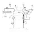
- the curling device 20 has a belt 21 and a curling plate 22, and the belt 21 and the curling plate 22 move in the direction of arrow X on both sides of the path (passage) of the container 1 (sealed container). It is arranged in each.
- a rope or the like can be used instead of the belt 21, a rope or the like.
- the belt 21 is driven by a plurality of drive wheels 21A attached to the curling device main body side (not shown) and circulates in the arrow Y direction.
- the curling plate 22 is fixed to the curling device main body by the bracket 22A.
- the belt 21 moves the container 1 in the direction of the arrow Y (FIG. 2) and, as shown in FIG. 3, presses the region of the container 1 below the capped portion toward the curling plate 22. Then, the curling plate 22 presses the side portion (including the hem portion 2A and the pull tab portion 2B of the cap 2) of the cap 2 capped on the container 1.
- the belt 21 circulates in the direction of the arrow Y (FIG. 2)
- the container 1 sandwiched between the belt 21 and the curling plate 22 rotates as shown by the arrow Z in FIG. 2, and the container 1 rotates.
- the hem portion 2A and the pull tab 2B of the cap 2 in contact with the curling plate 22 evenly adhere to the surface of the container 1 over the entire circumference.
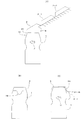
- the cross-sectional shape of the curling plate 22 (the cross-sectional shape of the portion that presses the container 1) is set so that the hem portion 2A of the cap 2 and the pull tab 2B can be normally brought into close contact with the surface of the container 1 without being folded (folded). It is configured to gradually change from upstream to downstream (from the left side to the right side in FIG. 2).
- the cross section BB (see FIG. 2) of the curling plate 22 is shown in FIG. 4 (A)
- the cross section CC is shown in FIG. 4 (B)
- the cross section DD is shown in FIG. 4 (C). ).
- the portion where the cap 2 of the container 1 is capped is also displayed.
- the curling plate 22 presses only the upper end portion of the cap 2.
- the curling plate 22 presses the hem portion 2A of the cap 2 excluding the pull tab portion 2B.
- the curling plate 22 presses the entire side portion of the cap 2 including the pull tab portion 2B.
- the caps 2-1 and 2-2 (indicated by the broken line) continuous with the cap 2 in the front row are stopped (damped) from advancing toward the container 1 by the cap 2 in the front row, but are continuous caps. 2-1 and 2-2 are urged to the front row cap 2 side by gravity.
- the container 1 is filled with a beverage as a content.
- the cap 2 is held in an inclined state with respect to the horizontal direction before being capped on the container 1, and the direction in which the container 1 moves (arrow U direction). ,
- the front edge (left edge in FIG.
- the cap 2 is provided with a pull tab 2B for being picked and pulled by a finger when the cap 2 is removed from the container 1, but the cap 2 is punched and molded by the cutting head 61.
- the pull tab 2B extends substantially horizontally as in the cap 2 shown in FIG.
- the pull tab 2-1B of the subsequent cap 2-1 enters the same portion (see FIG. 5C), so that the hem portion 2A and the outer surface of the container 1 are continuously inserted. In production, it is difficult to target and eliminate only the subsequent cap 2-1.
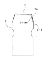
- the subsequent cap 2-1 (see FIG. 5C) is taken to the container 1 when the cap is capped, and the curling device 20 (FIG. 2) is connected to the belt 21.
- the succeeding cap 2-1 is placed in the container with the pull tab 2-1B of the succeeding cap 2-1 inserted between the hem 2A of the cap 2 and the outer surface of the container 1. It is in close contact with the surface of 1.
- the cap 2 (hem portion 2A, pull tab 2B) is in a normal state in which the double cap is not generated.
- the subsequent cap 2-1 Does not exist in the region below the mouth of the container 1, and the subsequent cap 2-1 will be present.
- the point that the pull tab 2-1B of the subsequent cap 2-1 is in close contact with the surface of the container while being inserted between the hem portion 2A of the cap 2 and the outer surface of the container 1. Then, it is the same as the double cap of FIG. 7, but a part of the subsequent cap 2-1 is turned up above the container 1, and the region where the cap 2 does not exist in the normal state where the double cap is not generated. That is, the subsequent cap 2-1 extends to the area above the container 1.
- the double cap of the type shown in FIG. 7 in close contact with the outer surface of the container 1 is the proximity sensor 3. Is detected by.
- the type of double cap shown in FIG. 8 that is, the double cap in which the subsequent cap 2-1 is turned up from the surface of the container 1 (in the present specification, it may be described as "turn-up type double cap”.
- the transmissive sensor 4 is an example of a sensor including a transmitter 4A (for example, a floodlight) and a receiver 4B (for example, a receiver).
- the detection device 10 for detecting the close contact type double cap is provided in the curling device 20.
- the belt 21 and the curling plate 22 cause the container 1 to move in the direction of arrow X while rotating in the direction of arrow Z.
- a belt 21 and a curling plate 22 are arranged on both sides (both sides in the vertical direction in FIG. 2) of the container 1 in a path of moving in the direction of arrow X while rotating in the direction of arrow Z, and the proximity sensor 3 is the path. It is provided at a position along the.
- six proximity sensors 3 are provided and are arranged in a region on the downstream side in the container moving direction of the path. As shown in FIGS. 2 and 3, the proximity sensor 3 is attached to the curling device main body at a position closest to the belt 21 via the bracket 3A. The reason why the six proximity sensors 3 are arranged in the illustrated embodiment will be described later.
- the detection region RI1 of the proximity sensor 3 is a region slightly below the cap 2 (including the hem portion 2A and the pull tab 2B) in the passing container 1. Therefore, in a normal state (a state in which the double cap does not exist) in which the cap 2 does not exist on the outer surface of the container 1 (the subsequent cap 2-1 is not in close contact with the container 2), the cap in the detection region RI1. 2 (2-1) does not exist.
- the detection region RI1 is a region in which the cap 2 is not detected in a normal state.
- the close contact type double cap is present (see FIG.
- the close contact type double cap (FIG. 7) is generated when the cap 2 and the subsequent cap 2-1 are pressed toward the container 1 by the curling plate 22 and come into close contact with the surface of the container 1.
- the close contact type double cap it follows the region on the surface of the container 1 (detection region RI1 in FIG. 3) in which the cap 2 does not exist in the normal state (the state in which the close contact type double cap does not exist).
- a part of the cap 2-1 is in close contact (see FIG. 7).
- the aluminum subsequent cap 2-1 is used as the proximity sensor 3 Detected by.
- the fact that the presence of aluminum is detected by the proximity sensor 3 means that the cap 2 (subsequent cap 2-1) is present on the surface of the container 1 (inspection area RI1 of the proximity sensor 3) where the cap 2 does not exist under normal conditions. Therefore, since it can be confirmed that a part of the subsequent cap 2-1 exists in the inspection area RI1, it is determined that the close contact type double cap has occurred. As will be described later with reference to FIG. 11, when the close contact type double cap is detected, an alarm or other necessary processing and procedure are executed.
- the proximity sensor 3 does not detect aluminum (cap 2, subsequent cap 2-1), so that the container 1 is normal (the container 1 is normal). It can be judged that the close contact type double cap is not generated).
- the subsequent cap 2-1 of the close contact type double cap is in close contact with which position in the circumferential direction of the container 1. It is impossible to know in advance what to do. Further, since the inspection area RI1 of the proximity sensor 3 cannot be accurately detected unless the distance is set to an extremely short distance from the proximity sensor 3, if the distance between the proximity sensor 3 and the container 1 is not extremely close, the following cap 2- The existence of 1 cannot be detected. Therefore, if only one proximity sensor 3 is provided, a close contact type double cap (FIG. 7) is generated depending on the circumferential position of the container 1 to which the subsequent cap 2-1 of the double cap is in close contact. Even so, there is a case where the succeeding cap 2-1 does not exist in the inspection area RI1 and the proximity sensor 3 cannot detect the occurrence of the close contact type double cap.
- each proximity sensor 3 is provided at equal intervals in the circumferential direction of the container 1. If six proximity sensors 3 are arranged at positions separated by 60 ° from the central angle of the container 1 so that the container 1 can be detected, the proximity sensors 3 can detect the entire circumferential direction of the container 1 equally. According to the inventor's experiment, six proximity sensors 3 are provided, and each proximity sensor 3 is arranged so as to detect the circumferential position of the container 1 separated from the adjacent proximity sensor 3 by a central angle of 60 °. Then, it was found that the subsequent cap 2-1 in the close contact type double cap of FIG.
- the dimension L in the upstream / downstream direction (horizontal direction in FIG. 2) of the region where the six proximity sensors 3 are provided is set to be slightly longer than the outer circumference of the container 1, so that it can be detected. The risk of leakage is reduced.
- the proximity sensor 3 is provided on the opposite side (belt 21 side) of the curling plate 22 with respect to the traveling path of the container 1. As described above, the proximity sensor 3 does not detect unless the distance to the caps 2 and 2-1 (made of aluminum) is short, and the distance condition is strict. Therefore, when the proximity sensor 3 is arranged at a position where the close contact type double cap can be detected on the curling plate 22 side, the proximity sensor 3 interferes with the curling plate 22. As is clear from FIG. 3, it is difficult to arrange the proximity sensor 3 on the curling plate 22 side. Therefore, in the illustrated embodiment, the proximity sensor 3 is not arranged on the curling plate 22 side with respect to the traveling path of the container 1, but is provided on the belt 21 side opposite to the curling plate 22.
- the proximity sensor 3 adopts a type that detects metal.
- the non-metal cap becomes a close contact type double cap (double cap)
- it can be detected by using a proximity sensor of a type that reacts to something other than metal.
- the detection of the "contact type double cap" by the proximity sensor can be applied to a cap made of a material different from the cap 2 of the illustrated embodiment by selecting an appropriate type of proximity sensor.
- the material that constitutes the cap to be detected and the material of the container must be different.
- the proximity sensor 3 can detect the close contact type double cap (FIG. 7) in close contact with the container surface, but the proximity sensor 3 cannot detect the "turn-up type double cap” shown in FIG.
- the position of the double cap that has been turned up depends on the degree of turning, but since it is located in the area above the container 1, the distance from the proximity sensor 3 is long, and the inspection area is located at a position where the "turned double cap” can be detected.
- Setting RI1 is difficult with the proximity sensor 3. Therefore, in the illustrated embodiment, the "turn-up type double cap" shown in FIG. 8 is detected by the transmissive sensor 4 (an example of a sensor including the transmitter 4A and the receiver 4B).
- the detection device 10A for detecting the curling type double cap is composed of a transmission type sensor 4 (transmission type fiber sensor) arranged in a path in which the container 1 of the curling device 20 moves.
- the transmission type sensor 4 is attached to the curling device main body via the bracket 4C in the region on the downstream side (right side in FIG. 2) of the path.
- the close contact type double cap detection device is represented by the reference numeral "10”.
- the turn-up type double cap detection device is represented by the code "10A”.
- both the detection device 10 for the close contact type double cap and the detection device 10A for the flip type double cap are provided.
- the transmissive sensor 4 is an example of a sensor including a transmitter 4A and a receiver 4B.
- the transmissive sensor 4 includes an irradiation side device 4A (for example, a floodlight) and a reception side sensor 4B (for example, a receiver), and the container 1 is conveyed to the floodlight 4A and the receiver 4B. It is placed on both sides of the route.
- the light emitter 4A irradiates the light receiver 4B with light LT.
- the receiver 4B When a flip-type double cap is generated, the receiver 4B does not receive the irradiation light LT because the subsequent cap 2-1 that is turned up blocks the irradiation light LT emitted from the floodlight 4A to the receiver 4B. As a result, the transmissive sensor 4 detects the occurrence of the flipped double cap.
- the detection region RI2 by the irradiation light LT of the transmissive sensor 4 is a region above the mouth of the cap 2 in the passing container 1. Therefore, in the normal state where the flip-type double cap is not generated, the subsequent cap 2-1 does not exist in the detection region RI2, and the irradiation light LT emitted from the floodlight 4A is received by the light receiver 4B without being blocked. Will be done. From this, it can be determined that the flip-type double cap is not generated.
- the detection region RI2 proceeds uninterrupted in the irradiation light LT in the normal state where the flip-type double cap is not generated, but in the state where the flip-type double cap is generated. This is an area where the irradiation light LT is blocked by the subsequent cap 2-1.
- an alarm or other necessary processing or procedure is executed.
- the floodlight 4A and the receiver 4B are arranged on both sides of the path of the container 1.
- the light receiver 4B is arranged at a position where the irradiation light LT reflected by the subsequent cap 2-1 can be received, the irradiation light emitted from the floodlight 4A is in a normal state where the flip-type double cap is not generated.
- the LT is not received by the receiver 4B, but if there is a flip-up type double cap, the irradiation light LT from the floodlight 4A is reflected by the flip-up subsequent cap 2-1 and detected by the receiver 4B.
- the flipped double cap As a result, it is possible to detect the occurrence of a flip-type double cap.
- the size, position, angle, shape, etc. of the flipped subsequent cap 2-1 are various, so in order to improve the detection accuracy of the flipped double cap, the flipped trailer It is necessary to arrange the light receiver 4B so that the light reflected by the cap 2-1 is surely received by the light receiver 4B.
- the sensor used for detecting the flip-up type double cap is not limited to the transmission type sensor 4 that irradiates light from the irradiator. Although not clearly shown, it is also possible to detect a flip-type double cap by, for example, irradiating ultrasonic waves and receiving them with an ultrasonic sensor. However, when the container 1 moves at a high speed (for example, about 40 m / min), it is difficult to detect the flip-type double cap by ultrasonic waves.
- the proximity sensor 3 is arranged on the upstream side and the transmissive sensor 4 is arranged on the downstream side in the moving path of the container 1.
- the transmissive sensor 4 can be arranged on the upstream side of the proximity sensor 3.
- the transmissive sensor 4 is arranged on the upstream side (left side in FIG. 10) in the moving path of the container 1, and the proximity sensor 3 is arranged on the downstream side of the transmissive sensor 4. Even if the transmissive sensor 4 is arranged on the upstream side of the proximity sensor 3 as shown in FIG. 10, the same operation and effect as in the case of FIG. 2 can be obtained.
- the proximity sensor 3 for detecting the close contact type double cap and the transmissive sensor 4 for detecting the curling type double cap are provided in the curling device 20, but the double cap detection device 10 10A can be provided at a place other than the curling device 20.
- the proximity sensor 3 has a mechanism for rotating the container, such as a combination of the belt 21 and the curling plate 22, in order to detect the "contact type double cap” which is a type of double cap in close contact with the container 1. It is preferable to combine them.
- the proximity sensors 3 are provided at locations other than the curling device 20, the number of proximity sensors 3 installed is not limited to the provision of six proximity sensors 3 as described above.
- the transmissive sensor 4 does not have a mechanism to be combined separately in order to detect the "turned-up type double cap" which is a turned-up type double cap, but the turning-up is completed at the time of inspection. Therefore, it is preferable to install the rotation mechanism such as the curling device 20 during or after passing through.
- the double cap detection device is a combination of the proximity sensor 3 and the transmissive sensor 4, but if the generation pattern of the double caps can be controlled, it is possible. , It is possible to detect with only one of the sensors.
- step S1 the proximity sensor 3 (FIGS. 2 and 3) detects a double cap (contact type double cap in FIG. 7) that is in close contact with the outer surface of the moving container 1 (FIG. 2). Judge whether or not. If the cap 2 (subsequent cap 2-1) is detected in the inspection area RI1 of the proximity sensor 3 (FIG. 3, the area where the cap 2 does not exist in the normal state), a close contact type double cap is generated in the container 1.
- step S1 If it is determined that the container 1 is (detected) (Yes in step S1) and the cap 2 is not detected in the inspection area RI1, the close contact type double cap is not generated (not detected) in the container 1 and the close contact type. It is determined that the double cap has not occurred (No in step S1). If the close contact type double cap is detected (step S1 is “Yes”), the process proceeds to step S3, and if the close contact type double cap is not detected (step S1 is “No”), the process proceeds to step S2.
- step S2 when the close contact type double cap is not detected, the transmissive sensor 4 (FIGS. 2 and 9) is used to cover the outer surface of the container 1 moving along the path with the double cap (turning type double cap in FIG. 8). , FIG. 8) is determined. If the cap 2 (subsequent cap 2-1 that is turned up away from the container surface) is detected in the inspection area RI2 of the transmissive sensor 4 (FIG. 9, the area where the cap 2 does not exist in the normal state), If it is determined that the container 1 has a flipped double cap (detected) (Yes in step S2) and the cap 2 is not detected in the inspection area RI2, a flipped double cap is generated in the container 1.
- step S2 determines that the flip-type double cap has not occurred.
- step S2 determines that the flip-type double cap has not occurred.
- step S2 determines that the flip-type double cap has not occurred.
- step S3 when a close contact type double cap or a flip type double cap is detected, a double cap is generated (detected), and it is determined that processing and countermeasures for it are necessary. Then, when a double cap (close contact type double cap or flip-up type double cap) is detected, necessary processing, for example, operation of an alarm device, suspension of operation of the manufacturing device 100 (FIG. 1), double cap Eliminate the container with the cap, investigate the cause of the double cap, and take countermeasures.
- necessary processing for example, operation of an alarm device, suspension of operation of the manufacturing device 100 (FIG. 1)
- double cap Eliminate the container with the cap, investigate the cause of the double cap, and take countermeasures.
- step S4 when the close contact type double cap and the flip type double cap are not detected, it is determined that the double cap has not occurred and the state is normal.
- steps S3 and S4 are completed, the process returns to step S1 and the same processing is executed for the subsequent container 1.
- step S1 and step S2 can be executed in reverse, and step S1 and step S2 can be executed at the same time.
- the proximity sensor 3 is provided along the path through which the container 1 moves, and the proximity sensor 3 is a double cap (adhesion type) that is in close contact with the outer surface of the container 1.
- Double cap In the normal state where the cap 2 (2-1) does not occur, the inspection area RI1 on the surface of the container in which the cap 2 (2-1) does not exist is detected. On the other hand, if the succeeding cap 2-1 is in close contact with the container surface (when the close contact type double cap in FIG. 7 occurs), a part of the succeeding cap 2-1 taken is present in the inspection area RI1. is doing.
- the proximity sensor 3 can detect the presence of the subsequent cap 2-1 and detect that the close contact type double cap is generated. .. Further, when arranging the proximity sensors 3, six (plurality) proximity sensors 3 are provided in a region in the longitudinal direction of the movement path of the container 1 within a range substantially the same as the outer peripheral dimension of the container 1, and the proximity sensors 3 are adjacent to each other. Are arranged so as to be equal to the range of the central angle of 60 ° in the circumferential direction of the container 1, and the circumferential direction of the rotating container 1 is inspected at equal intervals. Therefore, in the close contact type double cap, the subsequent cap 2-1 can be reliably detected at any position on the circumference of the container 1.
- the transmission type sensor 4 is provided along the path through which the container 1 moves, and when the container 1 has a flip-type double cap (FIG. 8). Is inspecting the detection region RI2 in which the cap 2 is not present under normal conditions. Therefore, when there is a trailing cap 2-1 that is turned up away from the outer circumference of the container (when a flipped double cap is generated), the trailing cap 2-1 that is turned up is the transmissive sensor 4.
- the receiving side 4B (for example, a receiver) cannot receive the irradiation light or the like. Therefore, when the container 1 passes through the location where the transmissive sensor 4 is provided, if the irradiated light or the like is not detected by the receiving side 4B, the subsequent cap 2- is separated from the outer periphery of the container and turned upward. Since 1 passes through the inspection area RI2 and blocks the irradiated light or the like, it is detected that a flip-type double cap is generated.
- the proximity sensor 3 and the transmissive sensor 4 are provided along the path through which the container 1 moves, and the subsequent cap 2-1 shown in FIG. 7 is attached to the surface of the container. Whether it is a close-fitting type double cap or a type of flip-up double cap in which the subsequent cap 2-1 shown in FIG. 8 is separated from the outer periphery of the container and turned upward, it is reliably detected. Can be done.
- the detection devices 10 and 10A are provided with the proximity sensor 3 and the transmissive sensor 4, respectively, but are not provided with the camera, and it is not necessary to take a picture of the container after the crown to be transported. ..
- the proximity sensor 3 and the transmissive sensor 4 are far cheaper than the camera, the cost of the entire production line can be reduced as compared with the case of providing an expensive camera.
- the container 1 is rotated by the belt 21 and the curling plate 22, and the hem portion 2A of the cap 2 is rotated. While the pull tab 2B is brought into close contact with the container 1, the close contact type double cap of the type shown in FIG. 7 can be detected. At the same time, the flipping type double cap of the type shown in FIG. 8 can be detected at approximately the same time as the detection of the close contact type double cap.
Landscapes
- Engineering & Computer Science (AREA)
- Mechanical Engineering (AREA)
- Closures For Containers (AREA)
- Sealing Of Jars (AREA)
- Closing Of Containers (AREA)
- Measuring Pulse, Heart Rate, Blood Pressure Or Blood Flow (AREA)
- Eye Examination Apparatus (AREA)
Priority Applications (5)
| Application Number | Priority Date | Filing Date | Title |
|---|---|---|---|
| EP21747643.1A EP4098570A4 (en) | 2020-01-31 | 2021-01-29 | DETECTION DEVICE |
| AU2021214348A AU2021214348A1 (en) | 2020-01-31 | 2021-01-29 | Detection device |
| CN202180012197.9A CN115298095B (zh) | 2020-01-31 | 2021-01-29 | 检测装置 |
| US17/795,820 US12344425B2 (en) | 2020-01-31 | 2021-01-29 | Detection device |
| JP2021574138A JP7519637B2 (ja) | 2020-01-31 | 2021-01-29 | 検出装置 |
Applications Claiming Priority (2)
| Application Number | Priority Date | Filing Date | Title |
|---|---|---|---|
| JP2020-014395 | 2020-01-31 | ||
| JP2020014395 | 2020-01-31 |
Publications (1)
| Publication Number | Publication Date |
|---|---|
| WO2021153715A1 true WO2021153715A1 (ja) | 2021-08-05 |
Family
ID=77078387
Family Applications (1)
| Application Number | Title | Priority Date | Filing Date |
|---|---|---|---|
| PCT/JP2021/003154 Ceased WO2021153715A1 (ja) | 2020-01-31 | 2021-01-29 | 検出装置 |
Country Status (7)
| Country | Link |
|---|---|
| US (1) | US12344425B2 (https=) |
| EP (1) | EP4098570A4 (https=) |
| JP (1) | JP7519637B2 (https=) |
| CN (1) | CN115298095B (https=) |
| AU (1) | AU2021214348A1 (https=) |
| TW (1) | TWI882065B (https=) |
| WO (1) | WO2021153715A1 (https=) |
Families Citing this family (2)
| Publication number | Priority date | Publication date | Assignee | Title |
|---|---|---|---|---|
| US12172790B1 (en) * | 2023-03-28 | 2024-12-24 | Amazon Technologies, Inc. | Visual indicators for optimized packing of multi-item packages |
| CN117182275A (zh) * | 2023-10-23 | 2023-12-08 | 宁波晶创科技有限公司 | 一种封焊机多层盖子检测机构及方法 |
Citations (8)
| Publication number | Priority date | Publication date | Assignee | Title |
|---|---|---|---|---|
| JPS61127404A (ja) * | 1984-11-20 | 1986-06-14 | 大阪機工株式会社 | カツプ充填機に於けるシ−ル供給装置 |
| JPH02140601A (ja) * | 1988-11-21 | 1990-05-30 | Morinaga Milk Ind Co Ltd | 2物体の重畳状態のずれを検出する方法及びその装置 |
| JPH05180621A (ja) * | 1991-12-27 | 1993-07-23 | Fuji Facom Corp | 瓶口天面シールの検査装置 |
| JPH05270527A (ja) * | 1992-03-30 | 1993-10-19 | Yamabun Denki:Kk | 容器上面シールの検査装置 |
| JPH0640408A (ja) * | 1992-07-14 | 1994-02-15 | Sanyuu:Kk | 有蓋容器の蓋部自動密閉装置 |
| US5387171A (en) | 1994-01-14 | 1995-02-07 | National Barbell Supply, Inc. | Variable resistance band exercise machine |
| JPH10236584A (ja) * | 1997-02-20 | 1998-09-08 | Yakult Honsha Co Ltd | 製品容器におけるキャップのシールチェッカ |
| US20100115887A1 (en) * | 2008-11-07 | 2010-05-13 | Delkor Systems, Inc. | Detection System |
Family Cites Families (14)
| Publication number | Priority date | Publication date | Assignee | Title |
|---|---|---|---|---|
| US3743853A (en) * | 1972-01-10 | 1973-07-03 | Electro Corp America | Adjustable proximity sensor |
| US6237418B1 (en) * | 1999-06-21 | 2001-05-29 | Benthos, Inc. | Method and apparatus for detecting misapplied caps on containers |
| US6104482A (en) * | 1999-12-02 | 2000-08-15 | Owens-Brockway Glass Container Inc. | Container finish check detection |
| US6473170B2 (en) * | 2001-01-19 | 2002-10-29 | White Cap, Inc. | Linear optical sensor for a closure |
| US6654117B1 (en) * | 2001-09-04 | 2003-11-25 | The Quaker Oats Company | Bottle cap sensor apparatus and method |
| JP5387171B2 (ja) | 2009-06-29 | 2014-01-15 | 王子ホールディングス株式会社 | 箱の不良検査方法 |
| JP5398903B2 (ja) * | 2010-02-16 | 2014-01-29 | 株式会社ヤクルト本社 | 連続ロータリー式充填包装機械 |
| WO2015177055A1 (en) * | 2014-05-21 | 2015-11-26 | Sacmi Verona S.P.A. | Carousel for processing containers |
| TWM490449U (en) * | 2014-07-18 | 2014-11-21 | Uni-President Entpr Corp | Detection device capable of detecting plastic bottle cap and label simultaneously |
| JP6283584B2 (ja) * | 2014-08-06 | 2018-02-21 | 澁谷工業株式会社 | 物品振分け装置 |
| DE102015211317B4 (de) * | 2015-06-19 | 2021-04-01 | Krones Ag | Inspektionsverfahren und -vorrichtung zur Verschlusskontrolle von Behältern |
| JP6613941B2 (ja) * | 2016-02-10 | 2019-12-04 | 株式会社ダイフク | 物品搬送設備 |
| US11993414B2 (en) * | 2021-12-13 | 2024-05-28 | Boomerang Water, Llc | Cleaning, filling, and capping containers |
| JP2024127404A (ja) * | 2023-03-09 | 2024-09-20 | 株式会社寺岡精工 | 販売データ処理装置、およびプログラム |
-
2021
- 2021-01-29 TW TW110103394A patent/TWI882065B/zh active
- 2021-01-29 WO PCT/JP2021/003154 patent/WO2021153715A1/ja not_active Ceased
- 2021-01-29 EP EP21747643.1A patent/EP4098570A4/en active Pending
- 2021-01-29 JP JP2021574138A patent/JP7519637B2/ja active Active
- 2021-01-29 AU AU2021214348A patent/AU2021214348A1/en active Pending
- 2021-01-29 US US17/795,820 patent/US12344425B2/en active Active
- 2021-01-29 CN CN202180012197.9A patent/CN115298095B/zh active Active
Patent Citations (8)
| Publication number | Priority date | Publication date | Assignee | Title |
|---|---|---|---|---|
| JPS61127404A (ja) * | 1984-11-20 | 1986-06-14 | 大阪機工株式会社 | カツプ充填機に於けるシ−ル供給装置 |
| JPH02140601A (ja) * | 1988-11-21 | 1990-05-30 | Morinaga Milk Ind Co Ltd | 2物体の重畳状態のずれを検出する方法及びその装置 |
| JPH05180621A (ja) * | 1991-12-27 | 1993-07-23 | Fuji Facom Corp | 瓶口天面シールの検査装置 |
| JPH05270527A (ja) * | 1992-03-30 | 1993-10-19 | Yamabun Denki:Kk | 容器上面シールの検査装置 |
| JPH0640408A (ja) * | 1992-07-14 | 1994-02-15 | Sanyuu:Kk | 有蓋容器の蓋部自動密閉装置 |
| US5387171A (en) | 1994-01-14 | 1995-02-07 | National Barbell Supply, Inc. | Variable resistance band exercise machine |
| JPH10236584A (ja) * | 1997-02-20 | 1998-09-08 | Yakult Honsha Co Ltd | 製品容器におけるキャップのシールチェッカ |
| US20100115887A1 (en) * | 2008-11-07 | 2010-05-13 | Delkor Systems, Inc. | Detection System |
Non-Patent Citations (1)
| Title |
|---|
| See also references of EP4098570A4 |
Also Published As
| Publication number | Publication date |
|---|---|
| US12344425B2 (en) | 2025-07-01 |
| CN115298095A (zh) | 2022-11-04 |
| TWI882065B (zh) | 2025-05-01 |
| TW202140336A (zh) | 2021-11-01 |
| JPWO2021153715A1 (https=) | 2021-08-05 |
| JP7519637B2 (ja) | 2024-07-22 |
| US20230072273A1 (en) | 2023-03-09 |
| AU2021214348A1 (en) | 2022-08-25 |
| EP4098570A1 (en) | 2022-12-07 |
| CN115298095B (zh) | 2026-03-27 |
| EP4098570A4 (en) | 2024-05-22 |
Similar Documents
| Publication | Publication Date | Title |
|---|---|---|
| JP6250644B2 (ja) | 空ビンを検査するための方法及び設備 | |
| WO2021153715A1 (ja) | 検出装置 | |
| JP5052403B2 (ja) | ガラス容器の検査機 | |
| CN102667453A (zh) | 罐的凹凸检测装置 | |
| JP6450815B1 (ja) | 外観検査装置及びブリスター包装機 | |
| JP6034961B2 (ja) | シェアログラフィック撮像マシン及び方法 | |
| JP6298033B2 (ja) | 外観検査装置 | |
| JP5357203B2 (ja) | 錠剤検査装置及びptp包装機 | |
| US20070127018A1 (en) | Inspection machine | |
| JP5754637B2 (ja) | ボトルの密封検査装置 | |
| JP5633005B2 (ja) | 異物検査装置 | |
| JP4324022B2 (ja) | 容器検査装置 | |
| JP6169341B2 (ja) | 密封容器の内圧検査装置および方法 | |
| JP2017072411A (ja) | 包装体の検査装置及び包装体の検査方法 | |
| JP6735226B2 (ja) | シール材の位置ズレ検査装置および検査方法 | |
| JP2015102360A (ja) | 密封容器の検査装置および検査方法 | |
| JP5331133B2 (ja) | 錠剤検査装置及びptp包装機 | |
| JP6360424B2 (ja) | 撮像装置および座屈検査装置 | |
| JP6094090B2 (ja) | リジェクト装置 | |
| JP2012117900A (ja) | 容器検査方法及び容器検査装置 | |
| EP3232185B1 (en) | Apparatus for detecting micro-cracks in lids | |
| JP2007057431A (ja) | 樹脂製瓶体の疵検査方法及び疵検査装置 | |
| JP7290825B2 (ja) | ラベル検査装置 | |
| JP2015081838A (ja) | 凹み缶・座屈缶検査装置 | |
| US11248985B2 (en) | Production method and production system that detect the integrity of the hermetic seal of a container containing a product |
Legal Events
| Date | Code | Title | Description |
|---|---|---|---|
| 121 | Ep: the epo has been informed by wipo that ep was designated in this application |
Ref document number: 21747643 Country of ref document: EP Kind code of ref document: A1 |
|
| ENP | Entry into the national phase |
Ref document number: 2021574138 Country of ref document: JP Kind code of ref document: A |
|
| ENP | Entry into the national phase |
Ref document number: 2021214348 Country of ref document: AU Date of ref document: 20210129 Kind code of ref document: A |
|
| NENP | Non-entry into the national phase |
Ref country code: DE |
|
| ENP | Entry into the national phase |
Ref document number: 2021747643 Country of ref document: EP Effective date: 20220831 |
|
| WWG | Wipo information: grant in national office |
Ref document number: 17795820 Country of ref document: US |