WO2021131786A1 - メス端子、コネクタ、及びワイヤーハーネス - Google Patents
メス端子、コネクタ、及びワイヤーハーネス Download PDFInfo
- Publication number
- WO2021131786A1 WO2021131786A1 PCT/JP2020/046258 JP2020046258W WO2021131786A1 WO 2021131786 A1 WO2021131786 A1 WO 2021131786A1 JP 2020046258 W JP2020046258 W JP 2020046258W WO 2021131786 A1 WO2021131786 A1 WO 2021131786A1
- Authority
- WO
- WIPO (PCT)
- Prior art keywords
- female terminal
- spring piece
- piece
- contact
- convex portion
- Prior art date
- Legal status (The legal status is an assumption and is not a legal conclusion. Google has not performed a legal analysis and makes no representation as to the accuracy of the status listed.)
- Ceased
Links
Images





Classifications
-
- H—ELECTRICITY
- H01—ELECTRIC ELEMENTS
- H01R—ELECTRICALLY-CONDUCTIVE CONNECTIONS; STRUCTURAL ASSOCIATIONS OF A PLURALITY OF MUTUALLY-INSULATED ELECTRICAL CONNECTING ELEMENTS; COUPLING DEVICES; CURRENT COLLECTORS
- H01R13/00—Details of coupling devices of the kinds covered by groups H01R12/70 or H01R24/00 - H01R33/00
- H01R13/02—Contact members
- H01R13/10—Sockets for co-operation with pins or blades
- H01R13/11—Resilient sockets
-
- H—ELECTRICITY
- H01—ELECTRIC ELEMENTS
- H01R—ELECTRICALLY-CONDUCTIVE CONNECTIONS; STRUCTURAL ASSOCIATIONS OF A PLURALITY OF MUTUALLY-INSULATED ELECTRICAL CONNECTING ELEMENTS; COUPLING DEVICES; CURRENT COLLECTORS
- H01R13/00—Details of coupling devices of the kinds covered by groups H01R12/70 or H01R24/00 - H01R33/00
- H01R13/02—Contact members
- H01R13/10—Sockets for co-operation with pins or blades
- H01R13/11—Resilient sockets
- H01R13/115—U-shaped sockets having inwardly bent legs, e.g. spade type
-
- H—ELECTRICITY
- H01—ELECTRIC ELEMENTS
- H01R—ELECTRICALLY-CONDUCTIVE CONNECTIONS; STRUCTURAL ASSOCIATIONS OF A PLURALITY OF MUTUALLY-INSULATED ELECTRICAL CONNECTING ELEMENTS; COUPLING DEVICES; CURRENT COLLECTORS
- H01R13/00—Details of coupling devices of the kinds covered by groups H01R12/70 or H01R24/00 - H01R33/00
- H01R13/02—Contact members
- H01R13/03—Contact members characterised by the material, e.g. plating, or coating materials
-
- H—ELECTRICITY
- H01—ELECTRIC ELEMENTS
- H01R—ELECTRICALLY-CONDUCTIVE CONNECTIONS; STRUCTURAL ASSOCIATIONS OF A PLURALITY OF MUTUALLY-INSULATED ELECTRICAL CONNECTING ELEMENTS; COUPLING DEVICES; CURRENT COLLECTORS
- H01R13/00—Details of coupling devices of the kinds covered by groups H01R12/70 or H01R24/00 - H01R33/00
- H01R13/02—Contact members
- H01R13/10—Sockets for co-operation with pins or blades
- H01R13/11—Resilient sockets
- H01R13/113—Resilient sockets co-operating with pins or blades having a rectangular transverse section
Definitions
- the present disclosure relates to female terminals, connectors, and wire harnesses.
- This application claims priority based on Japanese Patent Application No. 2019-237239 dated December 26, 2019, and incorporates all the contents described in the Japanese application.
- a male terminal and a female terminal are used as described in FIG. 9 of Patent Document 1.
- the female terminal typically includes a spring piece and a tubular portion for accommodating the spring piece.
- the male terminal inserted from the open end of the cylinder presses the spring piece, and the spring piece urges the male terminal.
- the male terminal and the female terminal are electrically connected.
- the spring piece of the female terminal described in Patent Document 1 is formed by bending a plurality of strips integrally with a plate material constituting a square tubular portion inside the tubular portion. Specifically, the strip extends from the open end of one of the four peripheral wall portions constituting the tubular portion. The strip is folded back from the end of the opening toward the inside of the cylinder. Further, the band member is folded back toward the opening end at an intermediate position of the band member. Further, the tip end portion of the band member is bent toward the peripheral wall portion side facing the one peripheral wall portion having the band member. The spring piece made of such a strip is cantilevered and supported by the open end of the peripheral wall portion of the tubular portion.
- each of the two spring pieces is cantilevered and supported by two facing peripheral wall portions of the four peripheral wall portions constituting the square tubular tubular portion.
- the two spring pieces facing each other sandwich the male terminal and urge.
- the female terminal of the present disclosure is A female terminal including a cylinder portion and a spring piece arranged inside the cylinder portion.
- the tubular portion includes an open end into which a male terminal is inserted, and a first inner surface and a second inner surface facing each other across the spring piece.
- the first inner surface is a surface that cantilever-supports the spring piece.
- the spring piece includes a front side region facing the male terminal, a back side region arranged on the first inner surface side, and at least one convex portion provided on the back side region. The convex portion locally protrudes toward the first inner surface.
- the connectors of the present disclosure are A female terminal of the present disclosure and a housing for holding the female terminal are provided.
- the wire harness of the present disclosure is The connector of the present disclosure and an electric wire connected to the female terminal are provided.
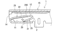
- FIG. 1 is a side view of the female terminal of the first embodiment as viewed from a direction orthogonal to the axial direction of the tubular portion.
- FIG. 2 is a cross-sectional view of the female terminal shown in FIG. 1 in which the tubular portion and the spring piece are cut along the II-II cutting line shown in FIG.
- FIG. 3 is a cross-sectional view of the female terminal shown in FIG. 1 in which the tubular portion and the spring piece are cut along the III-III cutting line shown in FIG.
- FIG. 4 is a cross-sectional view schematically showing an enlarged area on the surface side of the female terminal of the first embodiment.
- FIG. 5 is a cross-sectional view of the female terminal of the second embodiment, in which the tubular portion and the spring piece are cut in a plane orthogonal to the axial direction of the tubular portion.
- FIG. 6 is a cross-sectional view of the female terminal of the third embodiment, in which the tubular portion and the spring piece are cut in a plane orthogonal to the axial direction of the tubular portion.
- FIG. 7 is a cross-sectional view of the female terminal of the fourth embodiment, in which the tubular portion and the spring piece are cut in a plane orthogonal to the axial direction of the tubular portion.
- FIG. 8 is a cross-sectional view of the female terminal of the fifth embodiment, in which the tubular portion and the spring piece are cut in a plane orthogonal to the axial direction of the tubular portion.
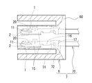
- FIG. 9 is a side view showing the connector of the embodiment and the wire harness of the embodiment.
- FIG. 10 is a graph showing the relationship between the contact load and the friction coefficient in Test Example 1.
- FIG. 11 is a graph showing the relationship between the contact pressure and the friction coefficient in Test Example 1.
- a female terminal that makes it easy to insert a male terminal is desired.
- the female terminal is typically used as an electrical connection member in a female connector.
- a female connector having a plurality of female terminals and a male connector having a plurality of male terminals are fitted together, each male terminal is inserted into each female terminal at the same time. Therefore, if it is difficult to insert each male terminal into each female terminal because the spring piece of each female terminal obstructs the insertion of each male terminal, the force when fitting the male connector and the female connector tends to increase. .. As the number of male terminals and the number of female terminals increases, the above-mentioned fitting force increases. Therefore, the burden on the operator increases in the connection between the male connector and the female connector.
- one of the purposes of the present disclosure is to provide a female terminal into which a male terminal can be easily inserted.
- Another object of the present disclosure is to provide a connector into which a male terminal can be easily inserted and a wire harness.
- the female terminal of the present disclosure, the connector of the present disclosure, and the wire harness of the present disclosure are excellent in the insertability of the male terminal.
- the present inventors have obtained the following findings regarding a female terminal including a tubular portion and a spring piece.
- the male terminal inserted into the tubular portion presses the spring piece toward the inner surface of the peripheral wall portion that cantilevers and supports the spring piece, for example, among the peripheral wall portions constituting the tubular portion. Due to this pressing, the portion of the spring piece facing the inner surface comes into contact with the inner surface. Further, as the male terminal advances in the tubular portion, the portion of the spring piece facing the inner surface slides on the inner surface. It can be said that the smaller the coefficient of friction between the spring piece and the inner surface in this sliding state, the less likely the spring piece will hinder the insertion of the male terminal.
- the male terminal easily enters the female terminal. Further, the larger the pressure when the portion of the spring piece facing the inner surface comes into contact with the inner surface, the smaller the friction coefficient tends to be.
- the female terminal of the present disclosure is based on the above findings.
- the above pressure that is, the pressure when the spring piece provided in the female terminal comes into contact with the inner surface of the tubular portion may be referred to as a contact pressure.
- the female terminal according to one aspect of the present disclosure is A female terminal including a cylinder portion and a spring piece arranged inside the cylinder portion.
- the tubular portion includes an open end into which a male terminal is inserted, and a first inner surface and a second inner surface facing each other across the spring piece.
- the first inner surface is a surface that cantilever-supports the spring piece.
- the spring piece includes a front side region facing the male terminal, a back side region arranged on the first inner surface side, and at least one convex portion provided on the back side region. The convex portion locally protrudes toward the first inner surface.
- the female terminal of the present disclosure can reduce the contact area between the spring piece and the first inner surface of the tubular portion by the convex portion. Since the contact area is small, the contact pressure is likely to increase as described later. Therefore, the coefficient of friction between the spring piece and the first inner surface of the cylinder when the male terminal is inserted into the cylinder tends to be small. Such a female terminal of the present disclosure is excellent in insertability of the male terminal because the male terminal can easily enter the tubular portion.
- the convex portion is convex.
- the portion and its vicinity are slippery on the first inner surface. Surface contact does not substantially occur depending on the shape, size, etc. of the convex portion. From these points as well, the female terminal of the present disclosure is excellent in the insertability of the male terminal.
- the width direction is defined as a direction orthogonal to both the direction in which the first inner surface and the second inner surface face each other and the axial direction.
- the backside region comprises a portion where each of the widthwise side edges approaches the first inner surface and the central portion in the width direction is curved away from the first inner surface.
- Examples of the convex portion include a form including the side edge portion.
- the above form has two convex parts. Therefore, the contact between the spring piece and the first inner surface of the tubular portion tends to be two-point contact. In this respect, the above-mentioned contact area tends to be small. Further, in the above embodiment, it is easy to maintain a state in which the two convex portions are in contact with the first inner surface and the portion of the spring piece other than the convex portions is not in contact with the first inner surface. Therefore, the state where the contact area is small is easily maintained.
- the width direction is defined as a direction orthogonal to both the direction in which the first inner surface and the second inner surface face each other and the axial direction.
- the back side region includes a portion where each of the lateral edge portions in the width direction is separated from the first inner surface and the central portion in the width direction is curved so as to approach the first inner surface.
- Examples of the convex portion include a form including the central portion.
- the above form includes one convex portion. Therefore, the contact between the spring piece and the first inner surface of the cylinder portion tends to be a single point contact. In this respect, the above-mentioned contact area tends to be small.
- the central portion in the width direction of the first inner surface is separated from the second inner surface, and the lateral edge portion of the first inner surface in the width direction approaches the second inner surface.
- a form having such a curved shape can be mentioned.
- the convex portion may have a form including an embossed portion.
- the convex portion can have a shape that allows point contact, for example. Therefore, the above-mentioned contact area tends to be smaller.
- a base material and a plating layer covering at least a part of the surface of the base material are provided.
- the portion covering the first inner surface and the portion covering the convex portion include a surface layer made of the same type of material.
- the material may be in the form of a kind of metal selected from the group consisting of pure tin, tin alloys, sterling silver, and silver alloys.
- the surface layer on the first inner surface side and the surface layer on the convex portion side are made of a material that easily adheres.
- the convex portion can penetrate the surface layer on the first inner surface side and come into contact with a portion inside the surface layer. As a result, adhesion is unlikely to occur. Therefore, the above-mentioned form can easily prevent the above-mentioned friction coefficient from increasing due to adhesion.
- At least one of the thickness of the portion covering the first inner surface and the portion covering the convex portion is thinner than the thickness of the portion covering the first inner surface and the portion other than the convex portion.
- the above-mentioned form can further prevent the above-mentioned friction coefficient from increasing due to adhesion.
- the spring piece is It is composed of strips that are bent into a predetermined shape.
- a base piece forming the front side region and a tip piece forming the back side region are provided.
- the base piece extends from the open end toward the inside of the cylinder.
- the tip piece is folded back from the base piece toward the open end. Examples thereof include a mode in which the ratio L1 / L2 is 0.51 or less when the length of the tip piece is L1 and the length of the base piece is L2.
- the spring constant of the spring piece tends to be large. Therefore, in the above form, the contact state with the male terminal can be maintained satisfactorily. Further, in the above embodiment, the total length of the strip material constituting the spring piece is shorter than that in the case where the length of the base piece is the same and the ratio L1 / L2 is more than 0.51. Therefore, the above-mentioned form is small and lightweight.
- the spring piece is It is composed of strips that are bent into a predetermined shape.
- a base piece forming the front side region and a tip piece forming the back side region are provided.
- the base piece extends from the open end toward the inside of the cylinder.
- the tip piece is folded back from the base piece toward the open end. Examples thereof include a form in which the length of the tip piece is less than 2.4 mm.
- the total length of the strip material constituting the spring piece is shorter than that in the case where the length of the tip piece is 2.4 mm or more. Therefore, the above-mentioned form is small and lightweight.
- the connector according to one aspect of the present disclosure is The female terminal according to any one of (1) to (9) above and a housing for holding the female terminal are provided.
- the connector of this disclosure has excellent insertability of male terminals.
- the connector of the present disclosure is a multi-pole connector including a plurality of female terminals
- the connector of the present disclosure and the male connector are easily fitted. Therefore, the connector of the present disclosure can reduce the burden on the operator in connection with the male connector.
- the wire harness according to one aspect of the present disclosure is The connector according to (10) above and an electric wire connected to the female terminal are provided.
- the wire harness of this disclosure has excellent insertability of male terminals.
- the connector provided in the wire harness of the present disclosure is the above-mentioned multi-pole connector, the connector and the male connector are easily fitted together. Therefore, the wire harness of the present disclosure can reduce the burden on the operator in connection with the male connector.
- FIG. 1 shows a direction in which the female terminal 1 of the first embodiment is orthogonal to the axial direction of the tubular portion 15 in a state where the female terminal 1 is arranged with the side where the tubular portion 15 cantilevers and supports the spring piece 2 as the lower side.
- FIG. 2 is a vertical cross-sectional view of the female terminal 1 of the first embodiment, in which the tubular portion 15 and the spring piece 2 are cut in a plane parallel to the axial direction and the height direction described later.
- FIG. 2 shows a portion of the tubular portion 15 for accommodating the spring piece 2.
- FIG. 3 is a cross-sectional view of the female terminal 1 of the first embodiment in which the tubular portion 15 and the spring piece 2 are cut in a plane orthogonal to the axial direction.
- FIG. 3 shows a portion of the spring piece 2 provided with the convex portion 20. It should be noted that FIGS. 1 to 3 and 5 to 9 described later show a state in which the male terminal 9 is not inserted into the tubular portion 15.
- the female terminal 1 of the first embodiment includes a tubular portion 15 and a spring piece 2.
- the spring piece 2 is arranged inside the tubular portion 15.
- a male terminal 9 is inserted into the tubular portion 15.
- the male terminal 9 inserted into the tubular portion 15 presses the spring piece 2, and the spring piece 2 urges the male terminal 9.
- the urging force of the spring piece 2 firmly maintains the contact state between the female terminal 1 and the male terminal 9.
- FIG. 1 virtually shows the male terminal 9 with a chain double-dashed line.
- the male terminal 9 is typically a rod-shaped member.
- the spring piece 2 has a specific shape. Specifically, the spring piece 2 includes at least one convex portion 20 in the back side region 25 that does not face the male terminal 9. The convex portion 20 locally protrudes toward the first inner surface 11 of the inner surface of the tubular portion 15 (FIG. 3). The first inner surface 11 is a surface that cantileverly supports the spring piece 2 (FIG. 2). In the female terminal 1, the convex portion 20 serves as a contact point with the first inner surface 11 of the spring piece 2. Such a female terminal 1 can reduce the contact area between the spring piece 2 and the first inner surface 11 of the tubular portion 15.
- a more detailed description will be given.
- the female terminal 1 of the first embodiment is typically a conductive member obtained by bending a plate material having a predetermined shape into a predetermined shape.
- the female terminal 1 includes a connection point with the male terminal 9 and a connection point with the electric wire 70 (FIG. 9 described later).
- Such a female terminal 1 is used, for example, as a member for electrically connecting a printed wiring board (not shown) connected to the male terminal 9 and an electronic / electrical device (not shown) connected to the electric wire 70.
- connection point with the male terminal 9 includes one tubular portion 15 and at least one spring piece 2.
- the tubular portion 15 of this example has a square tubular shape having a square end face shape and a cross-sectional shape (FIG. 3). Further, the female terminal 1 of this example includes one spring piece 2.
- connection point with the electric wire 70 typically includes a wire barrel portion 16 and an insulation barrel portion 17.
- FIG. 1 shows a state in which the female terminal 1 does not hold the electric wire 70. In this state, the band piece that wraps the electric wire 70 is not folded.
- the tubular portion 15 of this example includes four peripheral wall portions.
- a notch portion 18 to be a fold line is provided on the plate material before it is bent.
- the notch portion 18 is a linear notch extending along the axial direction of the tubular portion 15.
- the notch portion 18 bends the adjacent peripheral wall portions so as to be substantially orthogonal to each other. Therefore, the adjacent peripheral wall portions are arranged so as to be substantially orthogonal to each other.
- the corners formed by the adjacent peripheral walls are almost right angles.
- the four peripheral walls are equipped with two pairs of two peripheral walls facing each other.
- Each peripheral wall portion includes a portion composed of a flat flat plate piece.
- the left peripheral wall portion, the right peripheral wall portion, and the lower peripheral wall portion are composed of a substantially flat flat plate piece.
- the upper peripheral wall portion is composed of two plate pieces overlapping each other, but may be composed of one plate piece.
- the inner plate piece provided with the second inner surface 12 includes a bead portion protruding toward the inside of the tubular portion 15.
- the bead portion of this example is formed in a W shape.
- the tubular portion 15 includes a first inner surface 11 and a second inner surface 12 facing each other.
- the first inner surface 11 is the lower surface
- the second inner surface 12 is the upper surface.
- the first inner surface 11 is a substantially flat flat surface.
- the direction in which the first inner surface 11 and the second inner surface 12 face each other is referred to as a height direction.
- the height direction is the vertical direction in FIGS. 1 to 3 and 5 to 8 described later.
- the direction orthogonal to both the height direction and the axial direction of the tubular portion 15 is referred to as a width direction.
- the width direction is the direction in which two peripheral wall portions that do not have the first inner surface 11 and the second inner surface 12 face each other among the four peripheral wall portions. Further, the width direction is the left-right direction in FIGS. 3 and 5 to 8 described later.
- the axial direction is the left-right direction in FIGS. 1 and 2.
- Both ends of the tubular portion 15 are open. As shown in FIG. 1, one end of the tubular portion 15 is an open end 14 into which the male terminal 9 is inserted. On the other end side of the tubular portion 15, the wire barrel portion 16 and the insulation barrel portion 17 extend from the peripheral wall portion having the first inner surface 11.
- the spring piece 2 is sandwiched between the first inner surface 11 and the second inner surface 12 inside the tubular portion 15. Therefore, the spring piece 2 includes a region arranged on the first inner surface 11 side and a region arranged on the second inner surface 12 side.
- the region arranged on the second inner surface 12 side is the front side region 29 facing the male terminal 9.
- the front side region 29 includes a contact portion 290 in contact with the male terminal 9 (FIG. 2).
- the region arranged on the first inner surface 11 side is the back side region 25 that does not contact the male terminal 9.
- the spring piece 2 of this example is composed of a strip material bent into a predetermined shape. Specifically, as shown in FIG. 2, the strip extends from the opening end 14 of the peripheral wall portion having the first inner surface 11 of the four peripheral wall portions.
- the spring piece 2 is formed by bending the band member three times inside the tubular portion 15.
- the spring piece 2 made of such a band member is cantilevered and supported by the opening end 14 on the first inner surface 11 of the tubular portion 15 and is integrated with the tubular portion 15.
- the above-mentioned strip is folded back from the opening end 14 of the tubular portion 15 toward the inside of the tubular portion 15.
- the strip is folded back toward the opening end 14 at an intermediate position of the strip so that the first inner surface 11 side is inside the bend.
- the strip is bent from the first inner surface 11 side to the second inner surface 12 side at a position near the tip edge of the strip.
- press working or the like can be used for the bending work.
- the spring piece 2 of this example includes a base piece 22 and a tip piece 21.
- the base piece 22 constitutes the front side region 29.
- the tip piece 21 constitutes a part of the back side region 25.
- the base piece 22 is a portion folded back by the above-mentioned first bending. Therefore, the base piece 22 extends from the open end 14 toward the inside of the tubular portion 15. Further, the base piece 22 is arranged so as to intersect the first inner surface 11. Specifically, the base piece 22 is inclined so as to move away from the connection point with the opening end 14, that is, the root, and toward the first inner surface 11, that is, closer to the second inner surface 12. Therefore, the corner portion due to the second bending is arranged closer to the second inner surface 12 than the corner portion due to the first bending.
- the tip piece 21 is a portion folded back from the base piece 22 toward the opening end 14 by the second bending described above.
- the tip piece 21 and the base piece 22 are arranged so as to overlap each other in the height direction (FIG. 3). Therefore, the tip piece 21 does not come into contact with the male terminal 9.
- the tip edge of the spring piece 2 is arranged toward the second inner surface 12 side by the third bending described above.
- the tip edge is arranged upward in FIG.
- the outer corners are arranged facing the first inner surface 11. Therefore, this outer corner also constitutes the back side region 25. Further, the outer corner portion is a portion of the spring piece 2 that is arranged close to the first inner surface 11. That is, the outer corner portion is a portion where the distance to the first inner surface 11 is short.
- the spring piece 2 of this example includes two convex portions 20 at the outer corner portions described above.
- the back side region 25 is curved so that each of the side edge portions in the width direction approaches the first inner surface 11 and the central portion in the width direction is separated from the first inner surface 11. It has a part that has been removed. That is, the back side region 25 includes a portion curved toward the second inner surface 12, and a portion curved upward in FIG.
- the outer corner is the curved portion.
- the ridgeline of the outer corner is drawn as a convex curve above the above.
- Each convex portion 20 includes each side edge portion.
- FIG. 3 illustrates a case where each convex portion 20 is each side edge portion.
- the ridgeline forming the above-mentioned outer corner is curved over the entire ridgeline so as to draw one arc.
- the corner portion having such a curved shape is formed so as to warp the outer corner portion toward the second inner surface 12 side, for example, after the third bending or at the same time as the third bending.
- this curved shape is easier to form than the shapes shown in the fourth and fifth embodiments described later.
- the female terminal 1 of this example is excellent in manufacturability.
- the convex portion 20 is a portion of the spring piece 2 that is arranged closest to the first inner surface 11. That is, the convex portion 20 is the portion where the distance to the first inner surface 11 is the shortest. Therefore, when the male terminal 9 inserted into the tubular portion 15 presses the spring piece 2 toward the first inner surface 11, only the convex portion 20 or only the convex portion 20 and its vicinity is the first inner surface in the back side region 25. It touches 11. That is, in the back side region 25 of the spring piece 2, a state in which a portion other than the convex portion 20 is not in contact with the first inner surface 11 occurs. In this state, the contact area between the spring piece 2 and the first inner surface 11 of the tubular portion 15 is smaller than that in the case where the spring piece and the first inner surface 11 are in surface contact with each other.
- the above-mentioned outer corner portion has the above-mentioned specific curved shape, and the convex portion 20 is composed of the side edge portion of the spring piece 2. Therefore, the contact point of the spring piece 2 with the first inner surface 11 is a state close to two point contact by the biconvex portion 20 or two point contact. Therefore, the above-mentioned contact area is small. Further, the central portion in the width direction of the outer corner portion is difficult to contact the first inner surface 11 even if the spring piece 2 is pressed toward the first inner surface 11 by the male terminal 9.
- the contact area of the tubular portion 15 with the first inner surface 11 of the spring piece 2 is the contact area with the first inner surface 11 of the convex portion 20.
- the pressure applied by the convex portion 20 to the first inner surface 11, that is, the contact pressure is higher than in the case of the above-mentioned line contact or surface contact. Due to the high contact pressure, the coefficient of friction between the spring piece 2 and the first inner surface 11 tends to be small when the male terminal 9 is inserted into the tubular portion 15.
- the surface of the spring piece 2 and the surface of the first inner surface 11 are covered with a plating layer made of a material that easily adheres, as will be described later. Can be mentioned. If the above-mentioned contact pressure is large, the convex portion 20 can break through the easily stickable layer and come into contact with a portion inside the layer. As a result, it is difficult for the convex portion 20 and the first inner surface 11 to adhere to each other. Therefore, it is unlikely that the coefficient of friction will increase due to adhesion. As a result, the coefficient of friction between the spring piece 2 and the first inner surface 11 tends to be small.
- the distance between the front side region 29 of the spring piece 2 and the second inner surface 12 is widened. That is, in the tubular portion 15, the insertion point of the male terminal 9 becomes large. Therefore, the male terminal 9 can easily enter the tubular portion 15 without being hindered by the spring piece 2.
- the back side region 25 has the above-mentioned curved portion. Therefore, even if the spring piece 2 is elastically deformed so as to approach the first inner surface 11, the state in which the central portion in the width direction is separated from the first inner surface 11 is likely to be maintained. Therefore, line contact and even surface contact are unlikely to occur. Preferably, no surface contact occurs. That is, it is easy to maintain a state in which the contact between the spring piece 2 and the first inner surface 11 is a two-point point contact or a state close to the two-point point contact. Therefore, it is easy to maintain a state in which the contact area of the cylinder portion 15 with the first inner surface 11 of the spring piece 2 is small. From these facts, the convex portion 20 easily slides on the first inner surface 11.
- the length of the base piece 22 and the length of the tip piece 21 can be appropriately selected.
- the length of the base piece 22 is the length along the stretching direction of the base piece 22, and is the length from the corner portion due to the first bending described above to the corner portion due to the second bending described above.
- the length of the tip piece 21 is the length along the stretching direction of the tip piece 21, and is the length from the corner portion due to the second bending described above to the corner portion due to the third bending described above.
- the length of the tip piece 21 is L1 and the length of the base piece 22 is L2.
- the ratio L1 / L2 is 0.51 or less.
- the spring constant of the spring piece 2 tends to increase. Due to the large spring constant, the female terminal 1 tends to have a large contact load with respect to the male terminal 9. Therefore, the contact state between the female terminal 1 and the male terminal 9 can be easily maintained.
- the spring piece 2 having the ratio L1 / L2 of 0.51 or less the spring piece 2 has the same length L2 and is compared with the spring piece having the ratio L1 / L2 of more than 0.51.
- the total length of the band material that composes is short.
- the female terminal 1 is small and lightweight.
- the connector 6 (FIG. 9) provided with the female terminal 1 tends to be small and lightweight.
- the ratio L1 / L2 may be 0.50 or less, further 0.48 or less, and 0.45 or less.
- the ratio L1 / L2 may be 0.40 or less.
- the lower limit of the above ratio L1 / L2 is not particularly defined.
- the lower limit of the ratio L1 / L2 may be selected within a range in which the spring piece 2 satisfies a predetermined spring constant.
- the ratio L1 / L2 may be 0.2 or more.
- the length L1 of the tip piece 21 depends on the size of the female terminal 1, but for example, it may be less than 2.4 mm.
- the spring piece 2 having the length L1 of less than 2.4 mm constitutes the spring piece 2 as compared with the case where the length L1 is 2.4 mm or more.
- the total length of the strip is short.
- the female terminal 1 is small and lightweight.
- the connector 6 provided with the female terminal 1 tends to be small and lightweight.
- the length L1 may be 2.2 mm or less and 2.0 mm or less, although it depends on the size of the female terminal 1.
- the lower limit of the length L1 described above depends on the size of the female terminal 1, but for example, 1.0 mm or more can be mentioned.
- the length L1 may be 1.5 mm or more.
- the spring piece 2 may satisfy the above-mentioned ratio L1 / L2 of 0.51 or less and the above-mentioned length L1 of less than 2.4 mm.
- the female terminal 1 provided with such a spring piece 2 is compact and lightweight while ensuring a good contact state with the male terminal 9.
- the wire barrel portion 16 is electrically connected to the conductor 71 by holding the conductor 71 provided in the electric wire 70.
- the insulation barrel portion 17 holds an electrically insulating layer 72 provided on the electric wire 70.
- Both the wire barrel portion 16 and the insulation barrel portion 17 include a base on which the electric wire 70 is arranged and a pair of strips wrapping the electric wire 70.
- the base portion extends from the peripheral wall portion including the first inner surface 11 of the four peripheral wall portions constituting the tubular portion 15.
- the pair of strips extends from the side edges of the base.
- the female terminal 1 typically includes a base material 100 and a plating layer 101 that covers at least a part of the surface of the base material 100, as shown in FIG.
- FIG. 4 is a schematic cross-sectional view showing an enlarged region near the surface of the female terminal 1.
- the plate material constituting the female terminal 1 is mainly composed of the base material 100.
- the constituent material of the base material 100 is typically pure copper or a copper alloy.
- Copper alloys contain additive elements, with the balance consisting of Cu and unavoidable impurities.
- the additive element include Sn (tin), P (phosphorus), Zn (zinc), Fe (iron), nickel (Ni), silicon (Si) and the like.
- the total content of the added elements is, for example, 0.05% by mass or more and 40% by mass or less.
- Specific examples of the copper alloy include phosphor bronze containing Sn and P, brass containing Zn, and iron-containing copper containing Fe.
- the thickness of the base material 100 depends on the size of the female terminal 1, but for example, it may be 0.1 mm or more and 1.5 mm or less. If the thickness is 1.0 mm or less, and further 0.8 mm or less, the female terminal 1 tends to be small.
- the plating layer 101 typically contributes to reducing the contact resistance with the male terminal 9. Therefore, it is preferable that the female terminal 1 is provided with a plating layer 101 at least at a contact point with the male terminal 9. More specifically, it is preferable that the front side region 29 of the spring piece 2, particularly the contact portion 290 and its vicinity, and the portion of the second inner surface 12 facing the front side region 29 are provided with the plating layer 101.
- the entire front and back surfaces of the base material 100 may be provided with the plating layer 101.
- a female terminal 1 can be typically manufactured by using a covering plate material provided with a base material and a plating layer as a plate material before being bent into a predetermined shape. A plating layer having a uniform thickness is likely to be formed on the front and back surfaces of a flat plate material before being bent. Therefore, if the covering plate material is used, the female terminal 1 having the plating layer 101 on the entire front and back surfaces of the plate material forming the base material 100 can be manufactured with high productivity.
- the female terminal 1 of this example includes a plating layer 101 on the entire front and back surfaces of the plate material forming the base material 100. That is, in addition to the front side region 29 and the second inner surface 12, the surface of the back side region 25 of the spring piece 2 and the surface of the first inner surface 11 also include the plating layer 101.
- Examples of the constituent material of the plating layer 101 include metals such as pure tin, tin alloy, pure silver, silver alloy, pure nickel, and nickel alloy.
- Pure tin contains 99% by mass or more of Sn (tin), and the balance is composed of unavoidable impurities. Further, pure tin may contain Sn in an amount of 99.8% by mass or more.
- the tin alloy contains additive elements, the balance of which consists of Sn and unavoidable impurities. Specific examples of the tin alloy include an alloy containing tin and copper, an alloy containing tin and nickel, and the like. Examples of additive elements other than Cu and Ni include Zn and the like.
- Sterling silver contains 98% by mass or more of Ag (silver), and the balance is composed of unavoidable impurities. Further, the sterling silver may contain Ag in an amount of 98.5% by mass or more and 99.0% by mass or more.
- the silver alloy contains additive elements, the balance of which consists of Ag and unavoidable impurities. A known composition can be used for the silver alloy.
- Pure nickel contains 99% by mass or more of Ni (nickel), and the balance consists of unavoidable impurities. Further, pure nickel may contain 99.9% by mass or more of Ni.
- Nickel alloy contains additive elements, and the balance consists of Ni and unavoidable impurities. Examples of the additive element include Sn, Zn, Cu and the like.
- the plating layer 101 may be a single layer or a multi-layer.
- the constituent material of the surface layer 102 including the outermost surface is preferably a kind of metal selected from the group consisting of pure tin, tin alloy, sterling silver, and silver alloy.
- the female terminal 1 provided with the surface layer 102 made of pure tin tends to reduce the contact resistance with the male terminal 9.
- Pure silver has high conductivity. Therefore, the female terminal 1 provided with the surface layer 102 made of sterling silver tends to reduce the contact resistance with the male terminal 9.
- Tin alloys are usually harder than pure tin. Also, silver alloys are usually harder than sterling silver. Therefore, in the female terminal 1 provided with the surface layer 102 made of tin alloy or the surface layer 102 made of silver alloy, the male terminal 9 is slippery with respect to the spring piece 2. As a result, the male terminal 9 can easily enter the tubular portion 15.
- the plating layer 101 on the front surface side and the plating layer 101 on the back surface side of the plate material forming the base material 100 are made of the same type of material. In this case, it is easy to adjust the plating conditions. Therefore, the female terminal 1 having the plating layer 101 on the front and back surfaces of the plate material is manufactured with high productivity.
- the same kind of material is pure tin among the above four specific metals.
- the portion covering the first inner surface 11 and the portion covering the convex portion 20 include a surface layer 102 made of the same material.
- the same kind of metals are likely to adhere to each other. Therefore, when the convex portion 20 comes into contact with the first inner surface 11, the surface layer 102 on the convex portion 20 side and the surface layer 102 on the first inner surface 11 side tend to adhere to each other.
- the contact pressure is high as described above. Therefore, the convex portion 20 can break through the surface layer 102 on the first inner surface 11 side and come into contact with a portion inside the surface layer 102.
- the inner portion is, for example, an inner layer 103 if the plating layer 101 is a multilayer, and a base material 100 if the plating layer 101 is a single layer.
- a female terminal 1 can prevent an increase in the friction coefficient between the spring piece 2 and the first inner surface 11 due to adhesion.
- the thickness of the plating layer 101 can be appropriately selected.
- the total thickness of the plating layer 101 may be 0.1 ⁇ m or more and 10 ⁇ m or less.
- the thickness of the surface layer 102 is, for example, 0.05 ⁇ m or more and 4.0 ⁇ m or less, and further, 0.5 ⁇ m or more and 4.0 ⁇ m or less.
- the thickness of each inner layer 103 may be, for example, 0.05 ⁇ m or more and 1.0 ⁇ m or less, and further 0.1 ⁇ m or more and 1.0 ⁇ m or less.
- the thickness of the plating layer 101 may be substantially equal over the entire portion of the base material 100 where the plating layer 101 is provided. Alternatively, the thickness of the plating layer 101 may be partially different. For example, in the plating layer 101, the thickness of at least one of the portion covering the first inner surface 11 and the portion covering the convex portion 20 is such that the portion of the plating layer 101 other than the first inner surface 11 and the convex portion 20 is thickened. It may be thinner than the thickness of the covering part. In this case, when the convex portion 20 comes into contact with the first inner surface 11, the convex portion 20 tends to come into contact with a portion inside the surface layer 102. Therefore, it is more likely to prevent the friction coefficient between the spring piece 2 and the first inner surface 11 from increasing due to the adhesion.
- the first inner surface 11 and the convex portion 20 do not come into contact with the male terminal 9. Therefore, the thin thickness of the plating layer 101 on the first inner surface 11 and the convex portion 20 does not affect the reduction of contact resistance and the like. Therefore, one or both of the first inner surface 11 and the convex portion 20 may not be provided with the plating layer 101.
- the plating layer 101 may be partially crushed to be thinned by press working at the time of bending.
- the thin plating layer 101 may be partially formed by using masking or the like.
- the plating layer 101 has a multi-layer structure including a surface layer 102 and an inner layer 103.
- the inner layer 103 is made of an alloy containing tin and copper. That is, a plating layer 101 including a surface layer 102 made of pure tin and an inner layer 103 made of the alloy is provided on the front side region 29 and the second inner surface 12.
- the surface layer 102 can reduce the contact resistance with the male terminal 9, and the inner layer 103 is excellent in the insertability of the male terminal 9.
- the plating layer 101 may include a base layer (not shown) directly above the base material 100.
- Examples of the constituent material of the base layer include nickel and pure nickel alloy.
- the above-mentioned plating layer 101 having a multi-layer structure can be manufactured, for example, by forming a layer made of pure tin and then performing a heat treatment. By the heat treatment, Cu in the base material and Sn in the pure tin layer are alloyed to obtain an inner layer 103 made of an alloy containing tin and copper.
- the female terminal 1 of the first embodiment is provided with the convex portion 20 in the back side region 25 of the spring piece 2, so that the contact area between the spring piece 2 and the first inner surface 11 of the tubular portion 15 can be reduced.
- the contact area is small, the contact pressure is increased. Therefore, even when the surface layer 102 in which the convex portion 20 and the first inner surface 11 are easily adhered is provided, the coefficient of friction between the spring piece 2 and the first inner surface 11 tends to be small.
- the male terminal 9 since the male terminal 9 can easily enter the tubular portion 15, the male terminal 9 is excellent in insertability.
- the female terminal 1 of this example is provided with the above-mentioned specific curved portion in the back side region 25, so that the contact between the spring piece 2 and the first inner surface 11 tends to be two-point contact. Further, in the curved portion, the central portion in the width direction is unlikely to come into contact with the first inner surface 11.
- the female terminal 1 of the first embodiment is excellent in the insertability of the male terminal 9 because the contact area is likely to be small and the state in which the contact area is small is easily maintained.
- 5 to 8 are cross-sectional views in which the tubular portion 15 and the spring piece 2 are cut in a plane orthogonal to the axial direction of the tubular portion 15 in the same manner as in FIG. 3 described above. 5 to 8 show a portion of the spring piece 2 provided with the convex portion 20.
- the basic configuration of the female terminal 1 of the second to fifth embodiments is the same as that of the female terminal 1 of the first embodiment, and includes a tubular portion 15 and a spring piece 2 having a convex portion 20.
- differences from the first embodiment will be mainly described, and detailed description of configurations and effects that overlap with the first embodiment will be omitted.
- the female terminal 1 of the second embodiment includes a portion where the convex portion 20 is embossed.
- the convex portion 20 is formed so as to have a shape that allows point contact.
- the shape of the convex portion 20 include a conical shape and a pyramidal shape. Due to such a convex portion 20, the contact between the spring piece 2 and the first inner surface 11 of the tubular portion 15 tends to be a point contact. Further, by embossing the region near the side edge portion in the width direction at the outer corner portion described above, the region near the side edge portion tends to be locally hardened by work hardening.
- the female terminal 1 of the second embodiment can reduce the contact area between the spring piece 2 and the first inner surface 11 of the tubular portion 15. Further, the female terminal 1 of the second embodiment can easily maintain a state in which the contact area is small.
- the female terminal 1 of the third embodiment does not have a notch portion 18 between the peripheral wall portion provided with the first inner surface 11 and the peripheral wall portion adjacent to the peripheral wall portion.
- the peripheral wall portion provided with the first inner surface 11 is not a flat flat plate piece but a curved plate piece.
- the central portion in the width direction of the first inner surface 11 is separated from the second inner surface 12, and the lateral edge portion of the first inner surface 11 in the width direction is closer to the second inner surface 12. It has a curved shape.
- the first inner surface 11 is curved downward in FIG. 6.
- the ridgeline of the above-mentioned outer corner portion provided with the convex portion 20 has a curved shape that is convex toward the second inner surface 12 side. So to speak, the ridgeline of the outer corner portion has a curved shape opposite to that of the first inner surface 11. Therefore, each convex portion 20 easily makes point contact with the first inner surface 11. Further, in the back side region 25 of the spring piece 2, the portion other than the convex portion 20 is unlikely to come into contact with the first inner surface 11. Therefore, it is easy to maintain a state in which the contact between the spring piece 2 and the first inner surface 11 is close to two-point point contact or two-point point contact. Therefore, the female terminal 1 of the third embodiment can reduce the contact area between the spring piece 2 and the first inner surface 11 of the tubular portion 15. Further, the female terminal 1 of the third embodiment can easily maintain a state in which the contact area is small.
- the female terminal of the fourth embodiment will be described with reference to FIG. 7.
- the ridgeline of the outer corner portion provided with the convex portion 20 has a curved shape that is convex toward the first inner surface 11 side. So to speak, the ridgeline of the outer corner portion has a curved shape opposite to that of the first embodiment.
- FIG. 7 in the cross section of the spring piece 2, in the back side region 25, each of the side edge portions in the width direction is separated from the first inner surface 11, and the central portion in the width direction is the first inner surface. It is provided with a curved portion so as to approach 11.
- the outer corner is the curved portion.
- the ridgeline of the outer corner is drawn as a downwardly convex curve in FIG.
- the convex portion 20 includes a central portion in the width direction.
- the female terminal 1 of the fourth embodiment includes one convex portion 20. Therefore, the contact between the spring piece 2 and the first inner surface 11 tends to be a single point contact. Therefore, the female terminal 1 of the fourth embodiment can make the contact area between the spring piece 2 and the first inner surface 11 of the tubular portion 15 smaller.
- the female terminal 1 of the fifth embodiment includes a portion where the convex portion 20 is embossed with respect to the female terminal 1 of the fourth embodiment described above.
- Examples of the shape of the convex portion 20 include a conical shape and a pyramidal shape.
- the convex portion 20 having a shape capable of point contact is formed. Due to such a convex portion 20, the contact between the spring piece 2 and the first inner surface 11 of the tubular portion 15 tends to be a point contact. Therefore, the female terminal 1 of the fifth embodiment can reduce the contact area between the spring piece 2 and the first inner surface 11 of the tubular portion 15.
- the female terminal 1 of the sixth embodiment includes one tubular portion 15 and two spring pieces 2.
- the illustration of the sixth embodiment is omitted.
- the two spring pieces 2 are arranged so as to face each other inside the tubular portion 15.
- the first spring piece 2 is cantilevered and supported by the peripheral wall portion having the first inner surface 11 as in the first embodiment.
- the second spring piece 2 is cantilevered and supported by the peripheral wall portion having the second inner surface 12.
- a vertical cross section obtained by cutting the female terminal 1 of the sixth embodiment in a plane parallel to the axial direction and the height direction of the tubular portion 15 the first spring piece 2 and the second spring piece 2 are centered on the axis of the tubular portion 15. 2 is a line-symmetrical shape.
- each spring piece 2 The front side regions 29 of each spring piece 2 are arranged to face each other inside the tubular portion 15. The front side region 29 of both spring pieces 2 comes into contact with the male terminal 9 inserted into the tubular portion 15. Further, when the male terminal 9 presses the two spring pieces 2, the back side region 25 of the first spring piece 2 approaches the first inner surface 11 side. The back side region 25 of the second spring piece 2 approaches the second inner surface 12 side.
- the back side region 25 of the first spring piece 2 is arranged inside the tubular portion 15 so as to face the first inner surface 11.
- the back side region 25 is provided with a convex portion 20 as in the first embodiment. Therefore, when the male terminal 9 presses the two spring pieces 2 as described above, the convex portion 20 of the first spring piece 2 comes into contact with the first inner surface 11.
- the convex portion 20 makes point contact with the first inner surface 11.
- the back side region 25 of the second spring piece 2 is arranged inside the tubular portion 15 so as to face the second inner surface 12.
- the second spring piece 2 also has a convex portion 20 in the back side region 25. Therefore, when the male terminal 9 presses the two spring pieces 2 as described above, the convex portion 20 of the second spring piece 2 comes into contact with the second inner surface 12. Preferably, the convex portion 20 makes point contact with the second inner surface 12.
- the female terminal 1 of the sixth embodiment is provided with a convex portion 20 in the back side region 25 of each spring piece 2, so that the contact area between the first spring piece 2 and the first inner surface 11 of the tubular portion 15 and the second The contact area between the spring piece 2 and the second inner surface 12 of the tubular portion 15 can be reduced.
- the contact area is small, the contact pressure is increased. Therefore, even when the convex portion 20, the first inner surface 11, and the second inner surface 12 include the above-mentioned surface layer 102 that easily adheres, the coefficient of friction between the first spring piece 2 and the first inner surface 11 And the coefficient of friction between the second spring piece 2 and the second inner surface 12 tends to be small.
- the male terminal 9 can easily enter the tubular portion 15, and the male terminal 9 is excellent in insertability.
- the connector 6 of the embodiment includes the female terminal 1 described above and the housing 60.
- the female terminal 1 may be any of the above-described first to sixth embodiments. Note that FIG. 9 shows a part of the housing 60 cut out.
- the housing 60 is typically a molded body made of a resin composition. Further, the housing 60 is an integral body including a main body portion and a hood portion.
- the main body is a block-shaped portion that holds the female terminal 1.
- the hood portion is a bottomed tubular portion provided so as to cover the outer circumference of the main body portion.
- a hood portion provided in a male connector having a male terminal 9 is fitted between the outer peripheral surface of the main body portion and the inner peripheral surface of the hood portion. The illustration of the male connector is omitted.
- the connector 6 typically includes a plurality of female terminals 1 collectively in one housing 60.
- FIG. 9 illustrates a case where the connector 6 includes two female terminals 1, but the number of female terminals 1 can be changed as appropriate.
- thermoplastic resin examples include polybutylene terephthalate (PBT), polyethylene terephthalate (PET), polystyrene (PS), polycarbonate (PC) and the like.
- the resin composition may contain various fillers in addition to the main resin. Examples of the filler include glass fiber and the like.
- the wire harness 7 of the embodiment includes the connector 6 of the embodiment and the electric wire 70.
- the electric wire 70 is connected to the female terminal 1.
- the electric wire 70 includes a conductor 71 and an electrically insulating layer 72.
- the electrical insulating layer 72 covers the outer circumference of the conductor 71.
- the conductor 71 is typically a wire rod made of a conductive material such as copper, aluminum, or an alloy thereof.
- the electrically insulating layer 72 is typically composed of an electrically insulating material such as a resin.
- the female terminal 1 provided in the connector 6 of the embodiment and the wire harness 7 of the embodiment includes a spring piece 2 having a convex portion 20 as described above. Since the contact area between the spring piece 2 and the first inner surface 11 of the tubular portion 15 is small, the male terminal 9 can be easily inserted into the female terminal 1. Therefore, even when the connector 6 includes a plurality of female terminals 1, the female connector 6 and the male connector having the plurality of male terminals 9 are easily fitted. Therefore, in connecting the female connector 6 and the male connector, the burden on the operator is reduced.
- the coefficient of friction was measured using the following embossed pieces and flat pieces. Both the embossed piece and the flat piece are made of a covering plate material including a base material and a plating layer.
- the base material is a commercially available copper alloy plate used as a base material for female terminals and the like. The composition of this copper alloy is Cu-1.8% Ni-0.4% Si-1.1% Zn-0.1% Sn. The unit of the content of the additive element is mass%.
- the base material is a rectangular flat plate. The width of the base material is 40 mm. The length of the base material is 25 mm. The thickness of the base material is 0.25 mm.
- the plating layer includes a surface layer and an inner layer. The surface layer is made of pure tin. The inner layer is made of an alloy containing tin and copper. The plating layer was formed under known conditions. The total thickness of the plating layer is 1.0 ⁇ m.
- the embossed piece mimics a spring piece.
- the flat piece simulates the inner surface of the cylinder.
- the embossed piece has a hemispherical protrusion in the center.
- the radius R of the protrusion is 1.0 mm.
- the protrusions were formed by pressing the covering plate material.
- the flat piece is a test piece using the covering plate material as it is.
- the flat piece is a flat flat plate material that has not been specially processed.
- a sliding test is performed using the above-mentioned embossed piece and flat piece.
- the coefficient of friction is measured by this sliding test.
- the coefficient of friction here is the coefficient of dynamic friction.
- the sliding test is performed after cleaning the surface of the embossed piece and the surface of the flat piece with acetone.
- the sliding test is performed under the following conditions using a commercially available friction and wear tester.
- the friction and wear tester is a Tribometer CETR UMT-2 manufactured by Bruker.
- the contact load is selected from the range of 3N to 10N.
- the sliding speed is 0.2 mm / sec.
- the sliding distance is 5 mm.
- the protrusion of the embossed piece is brought into contact with the flat piece.
- the flat piece is slid at the above sliding speed in one direction by the above sliding distance.
- the maximum resistance force during sliding is measured by the above friction and wear tester.
- the dynamic friction coefficient is obtained by dividing the measured maximum resistance force by the contact load.
- the contact pressure (MPa) is calculated from the Hertz equation using the contact load (N).
- the angle of the surface of the arbitrary curved surface body having the principal curvature radii R 10 and R 11 and the arbitrary curved surface body having the principal curvature radii R 20 and R 21 including the principal curvatures 1 / R 10 and 1 / R 20 is ⁇ .
- the maximum contact surface pressure P 0 at the time of contact is expressed as follows from the Hertz equation.
- the angle ⁇ is the angle of each major axis of the above surface.
- the angle ⁇ 0 °.
- R 10 and R 11 are radii of curvature of the embossed piece.
- R 20 and R 21 are the radii of curvature of the flat piece. It is assumed that the flat piece has a very large curvature.
- P is the contact load (N).
- a and b are the semi-major axis radius (mm) and the semi-ellipsoidal radius (mm) of the elliptical contact surface in the semi-elliptical distribution based on the curved surface described above, respectively.
- ⁇ and ⁇ are parameters determined by the radius of curvature and the angle ⁇ .
- FIG. 10 is a graph showing the relationship between the contact load (N) and the friction coefficient.
- the horizontal axis represents the contact load (N).
- the vertical axis shows the coefficient of friction.
- FIG. 11 is a graph showing the relationship between the contact pressure and the friction coefficient.
- the horizontal axis indicates the contact pressure.
- the other contact pressures are shown as relative values with the minimum contact pressure (MPa) as a reference.
- the vertical axis shows the coefficient of friction.
- the present invention is not limited to these examples, but is indicated by the claims and is intended to include all modifications within the meaning and scope equivalent to the claims.
- the first inner surface 11 is not the flat flat surface described in the first embodiment but the curved shape described in the third embodiment.
- the spring piece 2 has a chevron-shaped structure in which the strip extending from the peripheral wall portion constituting the tubular portion 15 is bent twice, not a wound structure in which the strip member is bent three times.
- the spring piece 2 has a structure in which the strip material is folded back once.
- the spring piece 2 is composed of a metal piece joined to the first inner surface 11 of the tubular portion 15 instead of the strip material. Welding or the like can be used to join the metal pieces. Further, the convex portion 20 may be formed on the metal piece before joining.
- Female terminal 11 1st inner surface, 12 2nd inner surface, 14 Open end 15 Cylinder part, 16 Wire barrel part, 17 Insulation barrel part 18 Notch part 100 Base material, 101 Plating layer, 102 Surface layer, 103 Inner layer 2 Spring piece 20 Convex part, 21 Tip piece, 22 Base piece 25 Back side area, 29 Front side area, 290 Contact part 6 Connector, 60 Housing 7 Wire harness, 70 Electric wire, 71 Conductor, 72 Electrical insulation layer 9 Male terminal
Landscapes
- Coupling Device And Connection With Printed Circuit (AREA)
- Manufacturing Of Electrical Connectors (AREA)
Priority Applications (2)
| Application Number | Priority Date | Filing Date | Title |
|---|---|---|---|
| CN202080089984.9A CN114846697A (zh) | 2019-12-26 | 2020-12-11 | 阴端子、连接器、以及线束 |
| US17/786,991 US20230031959A1 (en) | 2019-12-26 | 2020-12-11 | Female terminal, connector and wiring harness |
Applications Claiming Priority (2)
| Application Number | Priority Date | Filing Date | Title |
|---|---|---|---|
| JP2019-237239 | 2019-12-26 | ||
| JP2019237239A JP2021106129A (ja) | 2019-12-26 | 2019-12-26 | メス端子、コネクタ、及びワイヤーハーネス |
Publications (1)
| Publication Number | Publication Date |
|---|---|
| WO2021131786A1 true WO2021131786A1 (ja) | 2021-07-01 |
Family
ID=76575220
Family Applications (1)
| Application Number | Title | Priority Date | Filing Date |
|---|---|---|---|
| PCT/JP2020/046258 Ceased WO2021131786A1 (ja) | 2019-12-26 | 2020-12-11 | メス端子、コネクタ、及びワイヤーハーネス |
Country Status (4)
| Country | Link |
|---|---|
| US (1) | US20230031959A1 (https=) |
| JP (1) | JP2021106129A (https=) |
| CN (1) | CN114846697A (https=) |
| WO (1) | WO2021131786A1 (https=) |
Families Citing this family (1)
| Publication number | Priority date | Publication date | Assignee | Title |
|---|---|---|---|---|
| CN120709753B (zh) * | 2025-08-15 | 2025-11-28 | 中航光电华亿(沈阳)电子科技有限公司 | 用于轨道交通变流系统的层压式弹片插孔结构及连接器 |
Citations (10)
| Publication number | Priority date | Publication date | Assignee | Title |
|---|---|---|---|---|
| JPH0523436A (ja) * | 1991-07-18 | 1993-02-02 | Glory Ltd | 硬貨リサイクルシステム |
| JPH069069A (ja) * | 1992-06-26 | 1994-01-18 | Ricoh Co Ltd | 記録紙給紙装置 |
| JPH08330009A (ja) * | 1995-05-30 | 1996-12-13 | Sumitomo Wiring Syst Ltd | 雌端子金具 |
| US6264509B1 (en) * | 2001-01-10 | 2001-07-24 | Yazaki North America, Inc. | High cycle terminal with protected failsafe contact |
| US6293833B1 (en) * | 2001-01-05 | 2001-09-25 | Yazaki North America | Low insertion force, high contact force terminal spring |
| JP2004022453A (ja) * | 2002-06-19 | 2004-01-22 | Sumitomo Wiring Syst Ltd | 端子金具 |
| JP2004311085A (ja) * | 2003-04-03 | 2004-11-04 | Sumitomo Wiring Syst Ltd | 雌端子金具 |
| JP2009037741A (ja) * | 2007-07-31 | 2009-02-19 | Auto Network Gijutsu Kenkyusho:Kk | コネクタの雌型端子 |
| WO2014030461A1 (ja) * | 2012-08-24 | 2014-02-27 | 株式会社オートネットワーク技術研究所 | コネクタ用めっき端子及びコネクタ用めっき端子の製造方法 |
| WO2014034300A1 (ja) * | 2012-08-29 | 2014-03-06 | 株式会社オートネットワーク技術研究所 | コネクタ端子及びコネクタ端子用材料 |
Family Cites Families (11)
| Publication number | Priority date | Publication date | Assignee | Title |
|---|---|---|---|---|
| JPH0523436U (ja) * | 1991-07-05 | 1993-03-26 | 矢崎総業株式会社 | 雌型端子 |
| JP2546255Y2 (ja) * | 1992-07-08 | 1997-08-27 | 矢崎総業株式会社 | 雌型端子金具 |
| JP3060891B2 (ja) * | 1995-05-08 | 2000-07-10 | 住友電装株式会社 | 雌形端子金具 |
| JP4858293B2 (ja) * | 2007-05-08 | 2012-01-18 | 住友電装株式会社 | 雌端子金具 |
| JP5343779B2 (ja) * | 2009-09-15 | 2013-11-13 | 住友電装株式会社 | 端子金具 |
| JP2012234651A (ja) * | 2011-04-28 | 2012-11-29 | Auto Network Gijutsu Kenkyusho:Kk | コネクタ端子とその製造方法およびコネクタ |
| JP2013098088A (ja) * | 2011-11-02 | 2013-05-20 | Sumitomo Wiring Syst Ltd | 雌型端子金具 |
| JP6497293B2 (ja) * | 2015-10-20 | 2019-04-10 | 株式会社オートネットワーク技術研究所 | 端子用金属板、端子及び端子対 |
| KR102471172B1 (ko) * | 2016-06-03 | 2022-11-25 | 후루카와 덴끼고교 가부시키가이샤 | 표면 처리재 및 그 제조 방법 및 표면 처리재를 이용하여 형성한 부품 |
| JP2019029216A (ja) * | 2017-07-31 | 2019-02-21 | 住友電装株式会社 | 雌端子 |
| JP7168626B2 (ja) * | 2020-10-23 | 2022-11-09 | 矢崎総業株式会社 | 接続端子 |
-
2019
- 2019-12-26 JP JP2019237239A patent/JP2021106129A/ja active Pending
-
2020
- 2020-12-11 CN CN202080089984.9A patent/CN114846697A/zh active Pending
- 2020-12-11 US US17/786,991 patent/US20230031959A1/en not_active Abandoned
- 2020-12-11 WO PCT/JP2020/046258 patent/WO2021131786A1/ja not_active Ceased
Patent Citations (10)
| Publication number | Priority date | Publication date | Assignee | Title |
|---|---|---|---|---|
| JPH0523436A (ja) * | 1991-07-18 | 1993-02-02 | Glory Ltd | 硬貨リサイクルシステム |
| JPH069069A (ja) * | 1992-06-26 | 1994-01-18 | Ricoh Co Ltd | 記録紙給紙装置 |
| JPH08330009A (ja) * | 1995-05-30 | 1996-12-13 | Sumitomo Wiring Syst Ltd | 雌端子金具 |
| US6293833B1 (en) * | 2001-01-05 | 2001-09-25 | Yazaki North America | Low insertion force, high contact force terminal spring |
| US6264509B1 (en) * | 2001-01-10 | 2001-07-24 | Yazaki North America, Inc. | High cycle terminal with protected failsafe contact |
| JP2004022453A (ja) * | 2002-06-19 | 2004-01-22 | Sumitomo Wiring Syst Ltd | 端子金具 |
| JP2004311085A (ja) * | 2003-04-03 | 2004-11-04 | Sumitomo Wiring Syst Ltd | 雌端子金具 |
| JP2009037741A (ja) * | 2007-07-31 | 2009-02-19 | Auto Network Gijutsu Kenkyusho:Kk | コネクタの雌型端子 |
| WO2014030461A1 (ja) * | 2012-08-24 | 2014-02-27 | 株式会社オートネットワーク技術研究所 | コネクタ用めっき端子及びコネクタ用めっき端子の製造方法 |
| WO2014034300A1 (ja) * | 2012-08-29 | 2014-03-06 | 株式会社オートネットワーク技術研究所 | コネクタ端子及びコネクタ端子用材料 |
Also Published As
| Publication number | Publication date |
|---|---|
| CN114846697A (zh) | 2022-08-02 |
| JP2021106129A (ja) | 2021-07-26 |
| US20230031959A1 (en) | 2023-02-02 |
Similar Documents
| Publication | Publication Date | Title |
|---|---|---|
| CN105453349B (zh) | 带有配件的导电片 | |
| CN105009386B (zh) | 连接结构体的制造方法、连接结构体、线束、压接部件和压接装置 | |
| US10177478B2 (en) | Board terminal and board connector | |
| US10418736B2 (en) | Metal plate for terminal, terminal, and terminal pair | |
| WO2010123061A1 (ja) | 端子金具及び端子金具付き電線 | |
| JP6957568B2 (ja) | 端子付き電線 | |
| WO2021029299A1 (ja) | 端子付き電線 | |
| CN104604038A (zh) | 连接端子 | |
| JP6936836B2 (ja) | 端子付き電線 | |
| WO2021131786A1 (ja) | メス端子、コネクタ、及びワイヤーハーネス | |
| US10727612B2 (en) | Crimp terminal, electrical wire with terminal, and manufacturing method for electrical wire with terminal | |
| US20170162969A1 (en) | Terminal pair and connector | |
| WO2021029303A1 (ja) | 端子付き電線 | |
| JP2024125554A (ja) | 圧着端子、及び、端子付き電線 | |
| JP5116512B2 (ja) | 圧着端子を用いた圧着方法 | |
| JP2010010072A (ja) | コンタクトキャリア | |
| JP7631995B2 (ja) | 電線導体および絶縁電線 | |
| JP5290812B2 (ja) | 高強度細径線用圧着端子 | |
| JP5757226B2 (ja) | 端子及び端子付き電線 | |
| WO2018092597A1 (ja) | 圧着端子および端子付き電線 | |
| US20220115802A1 (en) | Terminal | |
| CN111082232B (zh) | 端子金属部 | |
| CN108140998A (zh) | 带端子电线的制造方法、压接治具以及带端子电线 | |
| WO2013115079A1 (ja) | 端子 | |
| JP6053564B2 (ja) | 端子及び端子の製造方法 |
Legal Events
| Date | Code | Title | Description |
|---|---|---|---|
| 121 | Ep: the epo has been informed by wipo that ep was designated in this application |
Ref document number: 20905568 Country of ref document: EP Kind code of ref document: A1 |
|
| NENP | Non-entry into the national phase |
Ref country code: DE |
|
| 122 | Ep: pct application non-entry in european phase |
Ref document number: 20905568 Country of ref document: EP Kind code of ref document: A1 |