WO2021124976A1 - 撹拌・脱泡装置 - Google Patents
撹拌・脱泡装置 Download PDFInfo
- Publication number
- WO2021124976A1 WO2021124976A1 PCT/JP2020/045604 JP2020045604W WO2021124976A1 WO 2021124976 A1 WO2021124976 A1 WO 2021124976A1 JP 2020045604 W JP2020045604 W JP 2020045604W WO 2021124976 A1 WO2021124976 A1 WO 2021124976A1
- Authority
- WO
- WIPO (PCT)
- Prior art keywords
- outer ring
- container
- container holder
- rotation
- stirring
- Prior art date
- Legal status (The legal status is an assumption and is not a legal conclusion. Google has not performed a legal analysis and makes no representation as to the accuracy of the status listed.)
- Ceased
Links
Images
Classifications
-
- B—PERFORMING OPERATIONS; TRANSPORTING
- B01—PHYSICAL OR CHEMICAL PROCESSES OR APPARATUS IN GENERAL
- B01F—MIXING, e.g. DISSOLVING, EMULSIFYING OR DISPERSING
- B01F29/00—Mixers with rotating receptacles
- B01F29/10—Mixers with rotating receptacles with receptacles rotated about two different axes, e.g. receptacles having planetary motion
-
- B—PERFORMING OPERATIONS; TRANSPORTING
- B01—PHYSICAL OR CHEMICAL PROCESSES OR APPARATUS IN GENERAL
- B01D—SEPARATION
- B01D19/00—Degasification of liquids
- B01D19/0042—Degasification of liquids modifying the liquid flow
- B01D19/0052—Degasification of liquids modifying the liquid flow in rotating vessels, vessels containing movable parts or in which centrifugal movement is caused
-
- B—PERFORMING OPERATIONS; TRANSPORTING
- B01—PHYSICAL OR CHEMICAL PROCESSES OR APPARATUS IN GENERAL
- B01D—SEPARATION
- B01D19/00—Degasification of liquids
- B01D19/02—Foam dispersion or prevention
-
- B—PERFORMING OPERATIONS; TRANSPORTING
- B01—PHYSICAL OR CHEMICAL PROCESSES OR APPARATUS IN GENERAL
- B01F—MIXING, e.g. DISSOLVING, EMULSIFYING OR DISPERSING
- B01F29/00—Mixers with rotating receptacles
- B01F29/90—Mixers with rotating receptacles with stirrers having planetary motion
-
- B—PERFORMING OPERATIONS; TRANSPORTING
- B29—WORKING OF PLASTICS; WORKING OF SUBSTANCES IN A PLASTIC STATE IN GENERAL
- B29B—PREPARATION OR PRETREATMENT OF THE MATERIAL TO BE SHAPED; MAKING GRANULES OR PREFORMS; RECOVERY OF PLASTICS OR OTHER CONSTITUENTS OF WASTE MATERIAL CONTAINING PLASTICS
- B29B7/00—Mixing; Kneading
- B29B7/80—Component parts, details or accessories; Auxiliary operations
- B29B7/84—Venting or degassing ; Removing liquids, e.g. by evaporating components
- B29B7/845—Venting, degassing or removing evaporated components in devices with rotary stirrers
-
- B—PERFORMING OPERATIONS; TRANSPORTING
- B29—WORKING OF PLASTICS; WORKING OF SUBSTANCES IN A PLASTIC STATE IN GENERAL
- B29B—PREPARATION OR PRETREATMENT OF THE MATERIAL TO BE SHAPED; MAKING GRANULES OR PREFORMS; RECOVERY OF PLASTICS OR OTHER CONSTITUENTS OF WASTE MATERIAL CONTAINING PLASTICS
- B29B7/00—Mixing; Kneading
- B29B7/02—Mixing; Kneading non-continuous, with mechanical mixing or kneading devices, i.e. batch type
- B29B7/06—Mixing; Kneading non-continuous, with mechanical mixing or kneading devices, i.e. batch type with movable mixing or kneading devices
- B29B7/10—Mixing; Kneading non-continuous, with mechanical mixing or kneading devices, i.e. batch type with movable mixing or kneading devices rotary
- B29B7/106—Mixing; Kneading non-continuous, with mechanical mixing or kneading devices, i.e. batch type with movable mixing or kneading devices rotary using rotary casings
Definitions
- the present invention relates to a stirring / defoaming device, and more particularly, the present invention includes means for rotating and revolving the container, and at least one of stirring and defoaming the material contained in the container by rotating the container.
- a stirring / defoaming device that performs
- a stirring / defoaming device that agitates or defoams a single material or a mixed material contained in a container, provided with a means for rotating the container and a means for revolving the container, has been put into practical use.
- materials are single or mixed liquid (including fluid) materials in the fields of pharmaceuticals, chemical materials, foodstuffs, paints, semiconductor device materials, etc., or liquid materials and powder materials. Examples thereof include mixed materials (hereinafter, simply referred to as “materials”).
- Patent Document 1 Japanese Patent Application Laid-Open No. 8-332557.
- the present invention has been made in view of the above circumstances, and by realizing a mechanism capable of adjusting the rotation speed under a constant revolution speed, it is possible to suppress a temperature rise of the material during stirring and defoaming even if the material has a high viscosity. It is an object of the present invention to provide a stirring / defoaming device capable of preventing deterioration and deterioration of the material and obtaining a reliable stirring / defoaming action.
- the present invention solves the above problems by means of solutions as described below.
- This stirring / defoaming device includes a means for rotating and revolving the container, and is a stirring / defoaming device that rotates the container to perform at least one of stirring and defoaming of the material contained in the container.
- a plurality of container holders for holding the containers and each container holder are rotatably supported and rotatably provided around the first rotation shaft, and each container holder is provided on the first rotation shaft.
- a revolving member that revolves around, a first driving means that rotationally drives the revolving member, and an annular shape that surrounds the container holder so that the inner peripheral portion abuts on the outer peripheral portions of all the container holders.
- the container holder and the case are provided with an outer ring, a case formed so as to be hermetically sealed, at least the container, the container holder, the revolving member, and the outer ring, and a control unit for driving control.
- the outer ring is arranged so that the contact portion provided in an annular shape on the outer peripheral portion of the container holder and the contact surface provided on the inner peripheral portion of the outer ring come into contact with each other.
- the outer ring is rotated by revolving around the first rotating shaft and rotating by the frictional force received from the outer ring, and the revolving member and the central axis are aligned with each other to rotate the outer ring. It is a requirement that the outer ring rotating means is further provided.
- the revolution action and the rotation action of the container can be obtained, and the configuration of rotating the outer ring is realized, and the rotation speed can be variably adjusted while keeping the revolution speed constant.
- the rotation speed can be adjusted to a low speed, and the temperature rise of the material due to the frictional force, shearing force, etc. acting on the material can be suppressed. Deterioration and deterioration can be prevented, and deterioration of the stirring action can be prevented.
- the rotation speed can be adjusted at a high speed, and the stirring action can be further enhanced.
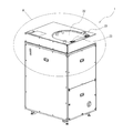
- FIG. 1 is a perspective view showing an example of a stirring / defoaming device according to an embodiment of the present invention.
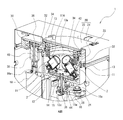
- FIG. 2 is a perspective sectional view of the stirring / defoaming device of FIG. 1 in part A.
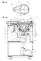
- 3A and 3B are schematic views showing an example of the stirring / defoaming device of FIG. 1, FIG. 3A is a sectional view taken along line BB, and FIG. 3B is a front sectional view.
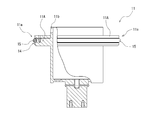
- FIG. 4 is a front view (partial cross-sectional view) showing an example of the container holder of the stirring / defoaming device of FIG.
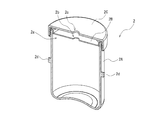
- FIG. 5 is a perspective sectional view showing an example of the container of the stirring / defoaming device of FIG.
- FIG. 1 is a perspective view (schematic view) showing an example of the stirring / defoaming device 1 according to the embodiment of the present invention
- FIG. 2 is a perspective sectional view (schematic view) of the part A thereof.
- FIG. 3A is a sectional view taken along line BB
- FIG. 3B is a front sectional view.
- members having the same function may be designated by the same reference numerals, and the repeated description thereof may be omitted.
- some bolts and nuts are not shown.
- the stirring / defoaming device 1 is provided with a means for rotating and revolving the container 2, and by rotating and revolving the container 2, the single material / mixed material contained in the container 2 is stirred and defoamed. It is a device for performing at least one of bubbles (hereinafter, simply referred to as "stirring / defoaming").
- the container holder 11, the container 2, the revolution member 12, and the outer ring 13 held by the container holder 11 are arranged inside the case 20.
- a material for forming these constituent elements a general structural material composed of a metal material and a resin material is used, and is not particularly limited (the same applies to other configurations). Duralumin or the like is preferably used as the strength member.
- the case 20 is configured to include a main body 21 and a lid 22 arranged on the upper part of the main body 21. Further, the lid portion 22 is fixed to the main body portion 21 so as to be opened and closed by using a hinge 23, and is formed in a structure that can be in close contact with the main body portion 21, so that the inside of the case 20 can be sealed. Is formed in. Further, a vacuum pump 10 for evacuating the inside of the case 20 is provided. The degree of vacuum by the vacuum pump 10 can be appropriately set, and as an example, the inside of the case 20 can be in a vacuum state of about atmospheric pressure to 10 [Pa].
- the container 2 can be attached to and detached from the container holder 11 by opening the lid portion 22.
- the inside of the case 20 can be made airtight, and in that state, the container 2 can be rotated and revolved to stir and defoam the material in the container 2.
- the lid portion 22 is formed by using a transparent resin material.
- the revolving member 12 has a first rotating shaft 12a penetrating the main body 21 of the case 20, and the first rotating shaft 12a can hold a vacuum in the case 20. It is rotatably supported and fixed to the main body 21 of the case 20 via a bearing (for example, a magnetic fluid bearing) 44.
- a bearing for example, a magnetic fluid bearing
- the shape of the revolving member 12 may be a disk shape, an arm shape, or a combination thereof.
- first rotating shaft 12a and the driving shaft 16a of the first driving means 16 are connected via the driving force transmitting means.
- the third pulley 24, the fourth pulley 26, and the transmission member (as an example, the timing belt) 28 are used as the driving force transmission means, but the present invention is not limited to this. Instead, a chain, gears, or the like may be used.
- the four container holders 11 are provided at equal intervals in the circumferential direction (that is, in a cross shape centered on the first rotation shaft 12a) to hold the four containers 2. It is not limited to this.
- the container holder 11 is formed in a bottomed cylindrical shape capable of holding the container 2 inside, and has a contact portion 11a provided in an annular shape on the outer peripheral portion. There is.
- the contact portion 11a is provided at the radial tip portion of the flange-shaped member 11A provided so as to extend in the radial direction from the outer peripheral portion of the container holder 11.
- the contact portion 11a has a concave groove 14 having a concave shape in the radial cross section provided in an annular shape along the circumferential direction at the radial tip portion of the collar-shaped member 11A.
- a resin elastic ring 15 is fitted in the concave groove 14 as an elastic body for contact.
- the resin elastic ring 15 an O-ring made of a rubber material (a silicon rubber having a hardness of 50 is preferable) is used, and the diameter is reduced in order to suppress the occurrence of slippage, bending, loosening, and the like. It is fitted in the concave groove 14 in a state where a predetermined tension is generated.
- an annular outer ring 13 for causing the container holder 11 to rotate is arranged in the case 20.
- the outer ring 13 is formed by using a stainless steel material or the like, but it may be formed by using another metal material or a resin material.
- the outer ring 13 according to the present embodiment has a contact surface 13a provided in an annular shape along the circumferential direction at the inner peripheral portion. ..
- the contact surface 13a is formed in a curved surface (conical inner surface) shape along the inner peripheral portion, and is in contact with the contact portion 11a (here, the resin elastic ring 15) provided on the outer peripheral portion of the container holder 11. It becomes the contact surface.
- the contact surface 13a is set at a predetermined angle (for example, the same angle as or about the same angle as ⁇ described above) with respect to the arrangement surface of the outer ring 13 provided parallel to the revolution surface of the revolution member 12. Is formed to have).
- the container holder 11 and the outer ring 13 configured as described above are arranged so that the contact portion 11a (here, the resin elastic ring 15) and the contact surface 13a are in contact with each other.
- the container 2 has a bottomed cylindrical main body 2A provided with an opening 2a at the top, an inner lid 2B fitted to the opening 2a, and an opening from the outside thereof. It is configured to include an outer lid 2C that is attached to the portion 2a.
- the material to be agitated and defoamed is put into the main body 2A through the opening 2a with the inner lid 2B and the outer lid 2C removed, and then the inner lid 2B is put into the main body 2A. And the outer lid 2C are fitted and combined.
- the inner lid 2B and the outer lid 2C are provided with the ventilation holes 2b and 2c, respectively, but the ventilation holes 2b and 2c may be omitted as appropriate. Further, the inner lid 2B and the outer lid 2C may be omitted as appropriate.
- a convex portion may be provided on the inner wall surface of the main body portion 2A (not shown).
- the container 2 is held by the container holder 11 by being fitted into the opening of the container holder 11 whose upper portion is formed in a cup shape from the bottom surface side.
- the protrusions 2d (two places in the present embodiment) provided on the outer peripheral portion of the main body portion 2A of the container 2 are engaged with the grooves 11b provided in the container holder 11. According to this, when the container holder 11 rotates (rotates), the container 2 is prevented from rotating in the circumferential direction with respect to the container holder 11, and the rotational force of the container holder 11 is transmitted to the container 2. , The action of rotating (rotating) the container 2 can be obtained.
- the rotational driving force thereof is transmitted to the first rotating shaft 12a via the driving force transmitting means, and the first rotating shaft 12a rotates, the rotational driving force is transmitted accordingly.
- the revolving member 12 rotates in the circumferential direction. Therefore, the container holder 11 fixed to the revolving member 12 and the container 2 held by the container holder 11 orbit around a constant orbit in the same plane centered on the central axis S of the first rotating shaft 12a ( Revolve).
- the revolving member 12 revolves, it is generated by the contact between the contact portion 11a (here, the resin elastic ring 15) on the outer peripheral portion of the container holder 11 and the contact surface 13a on the inner peripheral portion of the outer ring 13.
- the container holder 11 rotates due to the frictional force. Therefore, the container holder 11 and the container 2 held by the container holder 11 revolve and rotate. This makes it possible to effectively stir and defoam the material contained in the container 2.
- the revolution speed and the rotation speed at that time are appropriately set according to the material.
- the revolution direction of the revolution member 12 that is, the revolution direction of the container holder 11 and the container 2 held by the container holder 11, and the rotation direction of the container holder 11 and the container 2 held by the container holder 11 are defined. It is possible to reverse the direction. As a result, the stirring action of the material in the container 2 can be remarkably improved as compared with the case where the revolution direction and the rotation direction of the container holder 11 (container 2) are the same direction. This effect was demonstrated as a result of a comparative experiment using a high-viscosity stirring material such as grease.
- the container holder 11 is arranged so that its rotation axis R forms a predetermined angle ⁇ with respect to the arrangement surface of the outer ring 13 provided in parallel with the revolution surface of the revolution member 12. Has been done. As an example, it is set to 40 [°] ⁇ ⁇ ⁇ 60 [°]. In this way, by holding the container 2 in a state of being tilted by a predetermined angle and performing rotation and revolution, the stirring / defoaming action of the material inside the container 2 can be further enhanced.
- the total length of the contact surface 13a of the outer ring 13 (that is, the circumferential length of the contact surface 13a) is the total length of the resin elastic ring 15 of the contact portion 11a of the container holder 11. It is formed so as to be longer than the circumferential length of the contact portion 11a). According to this, the rotation speed (rotational speed [rpm]) can be increased with respect to the revolution speed (rotational speed [rpm]), and the stirring action can be enhanced.
- the total length of the contact surface 13a of the outer ring 13 is set to be twice the total length of the resin elastic ring 15 of the container holder 11.
- the revolution speed when the revolution speed is set to 800 [rpm], the rotation speed becomes 1600 [rpm] according to the ratio of the total length of the contact surface 13a to the total length of the resin elastic ring 15 (here 2: 1). It will be set.
- the revolution speed and the rotation speed are not the upper limit, and further speeding up can be achieved.
- the revolving member 12 and the central axis are aligned (that is, the axis that is the center of rotation is coaxial with the central axis S of the first rotating shaft 12a of the revolving member 12.
- An outer ring rotating means 30 for rotating the outer ring 13 is provided. More specifically, the outer ring rotating means 30 has a bearing member 32 that is arranged in the case 20 and rotatably supports the outer ring 13 so that the outer ring 13 and the central axis coincide with each other (that is, the center of rotation).
- the second rotating shaft 38 which is connected to the drive shaft 18a of the electric motor) 18 and is inserted so that the other end is located in the case 20, rotates, and the second rotating shaft 38 and the central axis are aligned with each other. (That is, the axis that is the center of rotation is coaxial with the central axis T of the second rotation shaft 38), and the second pulley 36, the first pulley 34, and the second pulley that are fixed to the second rotation shaft 38.
- the transmission member 42 is configured by using a timing belt, but the present invention is not limited to this, and a chain, gears, or the like may be used.
- the second rotating shaft 38 is rotatably supported and fixed to the main body 21 of the case 20 via a bearing (for example, a magnetic fluid bearing) 46 capable of holding a vacuum in the case 20. Since both the outer ring 13 and the first pulley 34 connected to the outer ring 13 have an annular structure, there is a problem in that the container 2 is attached to and detached from the container holder 11 by passing through the central opening space. Can be done without.
- the rotation speed of the outer ring 13 is set to 0 [rpm]
- the rotation speed of the container holder 11 and the container 2 can be set at a high speed (twice the revolution speed in the above example), as described above.
- a high stirring action can be obtained.
- the rotation speed of the outer ring 13 is appropriately set to a predetermined rotation speed [rpm] that is not 0, the rotation speeds of the container holder 11 and the container 2 can be appropriately reduced according to the rotation speed ( The higher the rotation speed of the outer ring 13, the lower the rotation speed of the container holder 11 and the container 2).
- the following effects can be obtained when the outer ring 13 is rotated in the direction opposite to the revolution direction of the revolution member 12. Specifically, if the rotation speed of the outer ring 13 is appropriately set to a predetermined rotation speed [rpm] that is not 0, the rotation speeds of the container holder 11 and the container 2 can be further increased according to the rotation speed (the rotation speed of the container holder 11 and the container 2 can be further increased. The higher the rotation speed of the outer ring 13, the higher the rotation speed of the container holder 11 and the container 2). Therefore, since the rotation speed of the container holder 11 and the container 2 can be set even higher, the stirring action can be further enhanced by applying the material to a material in which the problem of heat generation does not occur remarkably. It becomes.
- the stirring / defoaming device 1 has the following characteristic configurations. Specifically, it is provided with a rotation regulating means for restricting the rotation of the outer ring 13 so that the outer ring 13 is in a stationary state with respect to the case 20. According to this, it is possible to prevent the outer ring 13 from rotating and to apply a frictional force to the container holder 11 to obtain the rotation action of the container holder 11 and the container 2.
- the control unit controls the rotation of the outer ring 13 so that the outer ring 13 is in a stationary state with respect to the case 20 by performing the control generated by the drive means 18.
- the rotation speed of the second rotating shaft 38 connected to the second driving means 18 is 0 [rpm]
- the above-mentioned stationary state is obtained. Therefore, a rotation angle sensor or the like of the second rotating shaft 38 is provided for detection and detection.
- a configuration for controlling is conceivable.
- the revolution action and the rotation action of the container can be obtained, and the configuration of rotating the outer ring is realized, and the rotation speed is maintained at a constant revolution speed. It can be adjusted variably.
- the rotation speed can be adjusted to a low speed, and the temperature rise of the material due to the frictional force, shearing force, etc. acting on the material can be suppressed. Deterioration and deterioration can be prevented, and deterioration of the stirring action can be prevented.
- the rotation speed can be adjusted at a high speed, and the stirring action can be further enhanced.
Landscapes
- Chemical & Material Sciences (AREA)
- Chemical Kinetics & Catalysis (AREA)
- Engineering & Computer Science (AREA)
- Mechanical Engineering (AREA)
- Dispersion Chemistry (AREA)
- Mixers With Rotating Receptacles And Mixers With Vibration Mechanisms (AREA)
- Degasification And Air Bubble Elimination (AREA)
Priority Applications (3)
| Application Number | Priority Date | Filing Date | Title |
|---|---|---|---|
| US17/785,721 US12485368B2 (en) | 2019-12-16 | 2020-12-08 | Agitating/defoaming apparatus |
| KR1020227017832A KR20220110195A (ko) | 2019-12-16 | 2020-12-08 | 교반·탈포 장치 |
| CN202080087225.9A CN114845800B (zh) | 2019-12-16 | 2020-12-08 | 搅拌脱泡装置 |
Applications Claiming Priority (2)
| Application Number | Priority Date | Filing Date | Title |
|---|---|---|---|
| JP2019-226546 | 2019-12-16 | ||
| JP2019226546A JP7489085B2 (ja) | 2019-12-16 | 2019-12-16 | 撹拌・脱泡装置 |
Publications (1)
| Publication Number | Publication Date |
|---|---|
| WO2021124976A1 true WO2021124976A1 (ja) | 2021-06-24 |
Family
ID=76430337
Family Applications (1)
| Application Number | Title | Priority Date | Filing Date |
|---|---|---|---|
| PCT/JP2020/045604 Ceased WO2021124976A1 (ja) | 2019-12-16 | 2020-12-08 | 撹拌・脱泡装置 |
Country Status (6)
| Country | Link |
|---|---|
| US (1) | US12485368B2 (enExample) |
| JP (1) | JP7489085B2 (enExample) |
| KR (1) | KR20220110195A (enExample) |
| CN (1) | CN114845800B (enExample) |
| TW (1) | TWI864193B (enExample) |
| WO (1) | WO2021124976A1 (enExample) |
Cited By (1)
| Publication number | Priority date | Publication date | Assignee | Title |
|---|---|---|---|---|
| WO2023209852A1 (ja) * | 2022-04-27 | 2023-11-02 | 三星工業株式会社 | 撹拌・脱泡装置 |
Families Citing this family (2)
| Publication number | Priority date | Publication date | Assignee | Title |
|---|---|---|---|---|
| JP6785011B2 (ja) * | 2019-03-30 | 2020-11-18 | 株式会社写真化学 | 攪拌・脱泡装置 |
| CN114789015B (zh) * | 2022-06-23 | 2022-09-06 | 深圳市澳华集团股份有限公司 | 一种动物促生长的中草药饲料添加剂生产用乳化装置 |
Citations (5)
| Publication number | Priority date | Publication date | Assignee | Title |
|---|---|---|---|---|
| JPH04275868A (ja) * | 1991-01-14 | 1992-10-01 | I N R Kenkyusho:Kk | バレル研磨装置 |
| JPH08332367A (ja) * | 1995-06-08 | 1996-12-17 | Kameyama Tekkosho:Kk | 脱泡、混合機 |
| JP2008119603A (ja) * | 2006-11-13 | 2008-05-29 | Taiyo Giken:Kk | 撹拌装置 |
| WO2012172664A1 (ja) * | 2011-06-15 | 2012-12-20 | 三星工業株式会社 | 攪拌・脱泡装置 |
| WO2013183554A1 (ja) * | 2012-06-04 | 2013-12-12 | 三星工業株式会社 | 攪拌・脱泡装置およびその運転方法 |
Family Cites Families (9)
| Publication number | Priority date | Publication date | Assignee | Title |
|---|---|---|---|---|
| JP2003205449A (ja) | 2002-01-10 | 2003-07-22 | Daishinku Corp | バレル研磨装置 |
| JP2006192385A (ja) * | 2005-01-14 | 2006-07-27 | Inoue Mfg Inc | プラネタリーミキサー及びそれを用いた処理方法 |
| CN2782185Y (zh) * | 2005-04-07 | 2006-05-24 | 马为明 | 混料脱泡机 |
| JP2006305441A (ja) | 2005-04-27 | 2006-11-09 | Taiyo Giken:Kk | 撹拌脱泡装置 |
| JP2006305512A (ja) | 2005-05-02 | 2006-11-09 | Thinky Corp | 攪拌脱泡方法および攪拌脱泡装置 |
| CN102844087B (zh) * | 2010-04-27 | 2014-03-12 | 三星工业株式会社 | 搅拌·脱泡装置 |
| TWI501809B (zh) * | 2011-06-15 | 2015-10-01 | Mitsuboshi Kogyo Co Ltd | 攪拌及/或脫泡裝置 |
| TWM454182U (zh) * | 2012-11-26 | 2013-06-01 | Motion Dental Equipment Corp | 骨水泥攪拌機 |
| JP6798777B2 (ja) | 2015-10-23 | 2020-12-09 | 株式会社写真化学 | 攪拌・脱泡方法および攪拌・脱泡装置 |
-
2019
- 2019-12-16 JP JP2019226546A patent/JP7489085B2/ja active Active
-
2020
- 2020-12-08 KR KR1020227017832A patent/KR20220110195A/ko active Pending
- 2020-12-08 US US17/785,721 patent/US12485368B2/en active Active
- 2020-12-08 CN CN202080087225.9A patent/CN114845800B/zh active Active
- 2020-12-08 WO PCT/JP2020/045604 patent/WO2021124976A1/ja not_active Ceased
- 2020-12-15 TW TW109144188A patent/TWI864193B/zh active
Patent Citations (5)
| Publication number | Priority date | Publication date | Assignee | Title |
|---|---|---|---|---|
| JPH04275868A (ja) * | 1991-01-14 | 1992-10-01 | I N R Kenkyusho:Kk | バレル研磨装置 |
| JPH08332367A (ja) * | 1995-06-08 | 1996-12-17 | Kameyama Tekkosho:Kk | 脱泡、混合機 |
| JP2008119603A (ja) * | 2006-11-13 | 2008-05-29 | Taiyo Giken:Kk | 撹拌装置 |
| WO2012172664A1 (ja) * | 2011-06-15 | 2012-12-20 | 三星工業株式会社 | 攪拌・脱泡装置 |
| WO2013183554A1 (ja) * | 2012-06-04 | 2013-12-12 | 三星工業株式会社 | 攪拌・脱泡装置およびその運転方法 |
Cited By (1)
| Publication number | Priority date | Publication date | Assignee | Title |
|---|---|---|---|---|
| WO2023209852A1 (ja) * | 2022-04-27 | 2023-11-02 | 三星工業株式会社 | 撹拌・脱泡装置 |
Also Published As
| Publication number | Publication date |
|---|---|
| US12485368B2 (en) | 2025-12-02 |
| TWI864193B (zh) | 2024-12-01 |
| JP2021094512A (ja) | 2021-06-24 |
| KR20220110195A (ko) | 2022-08-05 |
| JP7489085B2 (ja) | 2024-05-23 |
| TW202130413A (zh) | 2021-08-16 |
| US20230049238A1 (en) | 2023-02-16 |
| CN114845800B (zh) | 2024-11-08 |
| CN114845800A (zh) | 2022-08-02 |
Similar Documents
| Publication | Publication Date | Title |
|---|---|---|
| WO2021124976A1 (ja) | 撹拌・脱泡装置 | |
| WO2012172664A1 (ja) | 攪拌・脱泡装置 | |
| CN102844087B (zh) | 搅拌·脱泡装置 | |
| CN104619405B (zh) | 一种用来均质化和分离样品的设备 | |
| US4111356A (en) | Centrifugal apparatus with flexible sheath | |
| EP2210655A1 (en) | Churning deaerator | |
| JPH07289873A (ja) | 溶剤等の攪拌・脱泡装置 | |
| WO2013183554A1 (ja) | 攪拌・脱泡装置およびその運転方法 | |
| JP2016073970A (ja) | 遠心機、及び伝達ユニット | |
| JP2013255866A (ja) | 遠心機、駆動機構、及び駆動方法 | |
| JP5506039B2 (ja) | 撹拌脱泡装置に使用する容器、及び、撹拌脱泡装置 | |
| JP6647754B2 (ja) | 遠心機、及び駆動機構 | |
| JP2000246082A (ja) | 混合攪拌装置 | |
| JP2008178850A (ja) | 被攪拌材の攪拌・脱泡装置 | |
| KR20200024551A (ko) | 다축 회전이 가능한 혼합장치 | |
| JP2016101576A (ja) | 遠心機、及び装着機構 | |
| JP2004074130A (ja) | 溶剤等の攪拌・脱泡方法とその装置 | |
| JP6611125B2 (ja) | 遠心機、及び回転機構 | |
| JP2015186795A (ja) | 遠心機、及び温調機構 | |
| TWI501809B (zh) | 攪拌及/或脫泡裝置 | |
| JP2013252516A (ja) | 遠心機、及び処理方法 | |
| JPH11309303A (ja) | 脱泡装置 | |
| JP2013202482A (ja) | 遠心機、それに用いられる変動成分重畳機構、及び、処理方法 | |
| JP7160290B2 (ja) | 遠心機、及びそれを用いた懸濁液調製方法 | |
| JP2016165679A (ja) | 遠心機、及びそれに適用される保持体 |
Legal Events
| Date | Code | Title | Description |
|---|---|---|---|
| 121 | Ep: the epo has been informed by wipo that ep was designated in this application |
Ref document number: 20900899 Country of ref document: EP Kind code of ref document: A1 |
|
| NENP | Non-entry into the national phase |
Ref country code: DE |
|
| 122 | Ep: pct application non-entry in european phase |
Ref document number: 20900899 Country of ref document: EP Kind code of ref document: A1 |