WO2021117584A1 - 電気化学セルおよび電気化学セルモジュール - Google Patents
電気化学セルおよび電気化学セルモジュール Download PDFInfo
- Publication number
- WO2021117584A1 WO2021117584A1 PCT/JP2020/044933 JP2020044933W WO2021117584A1 WO 2021117584 A1 WO2021117584 A1 WO 2021117584A1 JP 2020044933 W JP2020044933 W JP 2020044933W WO 2021117584 A1 WO2021117584 A1 WO 2021117584A1
- Authority
- WO
- WIPO (PCT)
- Prior art keywords
- electrochemical cell
- outer container
- inner container
- container
- electrochemical
- Prior art date
Links
- 238000010248 power generation Methods 0.000 claims abstract description 39
- 230000002093 peripheral effect Effects 0.000 claims abstract description 14
- 238000003487 electrochemical reaction Methods 0.000 claims abstract description 7
- 229920005989 resin Polymers 0.000 claims description 32
- 239000011347 resin Substances 0.000 claims description 32
- 229920001187 thermosetting polymer Polymers 0.000 claims description 14
- 238000005192 partition Methods 0.000 claims description 9
- 239000013543 active substance Substances 0.000 claims description 3
- 239000007773 negative electrode material Substances 0.000 claims description 2
- 210000004027 cell Anatomy 0.000 description 199
- 239000010410 layer Substances 0.000 description 63
- 239000000463 material Substances 0.000 description 39
- 239000007769 metal material Substances 0.000 description 22
- -1 polyethylene terephthalate Polymers 0.000 description 22
- 239000007788 liquid Substances 0.000 description 21
- 238000003825 pressing Methods 0.000 description 15
- 229920000139 polyethylene terephthalate Polymers 0.000 description 12
- 239000005020 polyethylene terephthalate Substances 0.000 description 12
- 229910052782 aluminium Inorganic materials 0.000 description 10
- XAGFODPZIPBFFR-UHFFFAOYSA-N aluminium Chemical compound [Al] XAGFODPZIPBFFR-UHFFFAOYSA-N 0.000 description 10
- 229910000838 Al alloy Inorganic materials 0.000 description 9
- 238000005304 joining Methods 0.000 description 9
- 239000008151 electrolyte solution Substances 0.000 description 8
- 229920006015 heat resistant resin Polymers 0.000 description 8
- 239000011247 coating layer Substances 0.000 description 7
- 239000010935 stainless steel Substances 0.000 description 7
- 229910001220 stainless steel Inorganic materials 0.000 description 7
- XLYOFNOQVPJJNP-UHFFFAOYSA-N water Substances O XLYOFNOQVPJJNP-UHFFFAOYSA-N 0.000 description 7
- 239000004698 Polyethylene Substances 0.000 description 6
- 239000012790 adhesive layer Substances 0.000 description 6
- 238000007600 charging Methods 0.000 description 6
- RYGMFSIKBFXOCR-UHFFFAOYSA-N Copper Chemical compound [Cu] RYGMFSIKBFXOCR-UHFFFAOYSA-N 0.000 description 5
- QVGXLLKOCUKJST-UHFFFAOYSA-N atomic oxygen Chemical compound [O] QVGXLLKOCUKJST-UHFFFAOYSA-N 0.000 description 5
- 229910052802 copper Inorganic materials 0.000 description 5
- 239000010949 copper Substances 0.000 description 5
- 239000000945 filler Substances 0.000 description 5
- 239000011810 insulating material Substances 0.000 description 5
- 229910052751 metal Inorganic materials 0.000 description 5
- 239000002184 metal Substances 0.000 description 5
- 239000001301 oxygen Substances 0.000 description 5
- 229910052760 oxygen Inorganic materials 0.000 description 5
- 229920000573 polyethylene Polymers 0.000 description 5
- 229910000881 Cu alloy Inorganic materials 0.000 description 4
- XEEYBQQBJWHFJM-UHFFFAOYSA-N Iron Chemical compound [Fe] XEEYBQQBJWHFJM-UHFFFAOYSA-N 0.000 description 4
- PXHVJJICTQNCMI-UHFFFAOYSA-N Nickel Chemical compound [Ni] PXHVJJICTQNCMI-UHFFFAOYSA-N 0.000 description 4
- 239000004743 Polypropylene Substances 0.000 description 4
- WYURNTSHIVDZCO-UHFFFAOYSA-N Tetrahydrofuran Chemical compound C1CCOC1 WYURNTSHIVDZCO-UHFFFAOYSA-N 0.000 description 4
- 239000007789 gas Substances 0.000 description 4
- 229920001155 polypropylene Polymers 0.000 description 4
- OKTJSMMVPCPJKN-UHFFFAOYSA-N Carbon Chemical compound [C] OKTJSMMVPCPJKN-UHFFFAOYSA-N 0.000 description 3
- KMTRUDSVKNLOMY-UHFFFAOYSA-N Ethylene carbonate Chemical compound O=C1OCCO1 KMTRUDSVKNLOMY-UHFFFAOYSA-N 0.000 description 3
- WHXSMMKQMYFTQS-UHFFFAOYSA-N Lithium Chemical compound [Li] WHXSMMKQMYFTQS-UHFFFAOYSA-N 0.000 description 3
- 239000002250 absorbent Substances 0.000 description 3
- 210000005056 cell body Anatomy 0.000 description 3
- 238000005520 cutting process Methods 0.000 description 3
- 229920001971 elastomer Polymers 0.000 description 3
- 238000010030 laminating Methods 0.000 description 3
- 229910052744 lithium Inorganic materials 0.000 description 3
- 239000005060 rubber Substances 0.000 description 3
- 239000002904 solvent Substances 0.000 description 3
- YEJRWHAVMIAJKC-UHFFFAOYSA-N 4-Butyrolactone Chemical compound O=C1CCCO1 YEJRWHAVMIAJKC-UHFFFAOYSA-N 0.000 description 2
- OIFBSDVPJOWBCH-UHFFFAOYSA-N Diethyl carbonate Chemical compound CCOC(=O)OCC OIFBSDVPJOWBCH-UHFFFAOYSA-N 0.000 description 2
- XTHFKEDIFFGKHM-UHFFFAOYSA-N Dimethoxyethane Chemical compound COCCOC XTHFKEDIFFGKHM-UHFFFAOYSA-N 0.000 description 2
- 229910012851 LiCoO 2 Inorganic materials 0.000 description 2
- GWEVSGVZZGPLCZ-UHFFFAOYSA-N Titan oxide Chemical compound O=[Ti]=O GWEVSGVZZGPLCZ-UHFFFAOYSA-N 0.000 description 2
- RTAQQCXQSZGOHL-UHFFFAOYSA-N Titanium Chemical compound [Ti] RTAQQCXQSZGOHL-UHFFFAOYSA-N 0.000 description 2
- 239000004840 adhesive resin Substances 0.000 description 2
- 229920006223 adhesive resin Polymers 0.000 description 2
- 150000001450 anions Chemical class 0.000 description 2
- 150000001768 cations Chemical class 0.000 description 2
- 239000002131 composite material Substances 0.000 description 2
- 238000010277 constant-current charging Methods 0.000 description 2
- 230000007423 decrease Effects 0.000 description 2
- 230000005611 electricity Effects 0.000 description 2
- 229910052742 iron Inorganic materials 0.000 description 2
- 229910000625 lithium cobalt oxide Inorganic materials 0.000 description 2
- 229910003002 lithium salt Inorganic materials 0.000 description 2
- 159000000002 lithium salts Chemical class 0.000 description 2
- BFZPBUKRYWOWDV-UHFFFAOYSA-N lithium;oxido(oxo)cobalt Chemical compound [Li+].[O-][Co]=O BFZPBUKRYWOWDV-UHFFFAOYSA-N 0.000 description 2
- 238000004519 manufacturing process Methods 0.000 description 2
- 238000002844 melting Methods 0.000 description 2
- 230000008018 melting Effects 0.000 description 2
- 238000000034 method Methods 0.000 description 2
- 229910052759 nickel Inorganic materials 0.000 description 2
- 239000003960 organic solvent Substances 0.000 description 2
- 229920003207 poly(ethylene-2,6-naphthalate) Polymers 0.000 description 2
- 239000011112 polyethylene naphthalate Substances 0.000 description 2
- 229920000642 polymer Polymers 0.000 description 2
- 239000002861 polymer material Substances 0.000 description 2
- RUOJZAUFBMNUDX-UHFFFAOYSA-N propylene carbonate Chemical compound CC1COC(=O)O1 RUOJZAUFBMNUDX-UHFFFAOYSA-N 0.000 description 2
- 238000007789 sealing Methods 0.000 description 2
- YLQBMQCUIZJEEH-UHFFFAOYSA-N tetrahydrofuran Natural products C=1C=COC=1 YLQBMQCUIZJEEH-UHFFFAOYSA-N 0.000 description 2
- GEWWCWZGHNIUBW-UHFFFAOYSA-N 1-(4-nitrophenyl)propan-2-one Chemical compound CC(=O)CC1=CC=C([N+]([O-])=O)C=C1 GEWWCWZGHNIUBW-UHFFFAOYSA-N 0.000 description 1
- 244000043261 Hevea brasiliensis Species 0.000 description 1
- UFHFLCQGNIYNRP-UHFFFAOYSA-N Hydrogen Chemical compound [H][H] UFHFLCQGNIYNRP-UHFFFAOYSA-N 0.000 description 1
- 229910013063 LiBF 4 Inorganic materials 0.000 description 1
- 229910013684 LiClO 4 Inorganic materials 0.000 description 1
- 229910010941 LiFSI Inorganic materials 0.000 description 1
- 229910013290 LiNiO 2 Inorganic materials 0.000 description 1
- 229910013870 LiPF 6 Inorganic materials 0.000 description 1
- HBBGRARXTFLTSG-UHFFFAOYSA-N Lithium ion Chemical compound [Li+] HBBGRARXTFLTSG-UHFFFAOYSA-N 0.000 description 1
- 239000004640 Melamine resin Substances 0.000 description 1
- 229920000877 Melamine resin Polymers 0.000 description 1
- 239000004677 Nylon Substances 0.000 description 1
- 229920003171 Poly (ethylene oxide) Polymers 0.000 description 1
- 239000004952 Polyamide Substances 0.000 description 1
- XUIMIQQOPSSXEZ-UHFFFAOYSA-N Silicon Chemical compound [Si] XUIMIQQOPSSXEZ-UHFFFAOYSA-N 0.000 description 1
- 229910000639 Spring steel Inorganic materials 0.000 description 1
- 229910021536 Zeolite Inorganic materials 0.000 description 1
- KFDQGLPGKXUTMZ-UHFFFAOYSA-N [Mn].[Co].[Ni] Chemical compound [Mn].[Co].[Ni] KFDQGLPGKXUTMZ-UHFFFAOYSA-N 0.000 description 1
- 239000000853 adhesive Substances 0.000 description 1
- 230000001070 adhesive effect Effects 0.000 description 1
- 239000002390 adhesive tape Substances 0.000 description 1
- 238000005452 bending Methods 0.000 description 1
- OJIJEKBXJYRIBZ-UHFFFAOYSA-N cadmium nickel Chemical compound [Ni].[Cd] OJIJEKBXJYRIBZ-UHFFFAOYSA-N 0.000 description 1
- 239000002041 carbon nanotube Substances 0.000 description 1
- 229910021393 carbon nanotube Inorganic materials 0.000 description 1
- 239000003575 carbonaceous material Substances 0.000 description 1
- 238000006243 chemical reaction Methods 0.000 description 1
- 239000011248 coating agent Substances 0.000 description 1
- 238000000576 coating method Methods 0.000 description 1
- 229910017052 cobalt Inorganic materials 0.000 description 1
- 239000010941 cobalt Substances 0.000 description 1
- GUTLYIVDDKVIGB-UHFFFAOYSA-N cobalt atom Chemical compound [Co] GUTLYIVDDKVIGB-UHFFFAOYSA-N 0.000 description 1
- 150000001875 compounds Chemical class 0.000 description 1
- 230000006835 compression Effects 0.000 description 1
- 238000007906 compression Methods 0.000 description 1
- 238000010280 constant potential charging Methods 0.000 description 1
- 238000010281 constant-current constant-voltage charging Methods 0.000 description 1
- QHGJSLXSVXVKHZ-UHFFFAOYSA-N dilithium;dioxido(dioxo)manganese Chemical compound [Li+].[Li+].[O-][Mn]([O-])(=O)=O QHGJSLXSVXVKHZ-UHFFFAOYSA-N 0.000 description 1
- IEJIGPNLZYLLBP-UHFFFAOYSA-N dimethyl carbonate Chemical compound COC(=O)OC IEJIGPNLZYLLBP-UHFFFAOYSA-N 0.000 description 1
- HNPSIPDUKPIQMN-UHFFFAOYSA-N dioxosilane;oxo(oxoalumanyloxy)alumane Chemical compound O=[Si]=O.O=[Al]O[Al]=O HNPSIPDUKPIQMN-UHFFFAOYSA-N 0.000 description 1
- 238000006073 displacement reaction Methods 0.000 description 1
- 239000003822 epoxy resin Substances 0.000 description 1
- 230000006870 function Effects 0.000 description 1
- 229910021389 graphene Inorganic materials 0.000 description 1
- 229910002804 graphite Inorganic materials 0.000 description 1
- 239000010439 graphite Substances 0.000 description 1
- 229910021385 hard carbon Inorganic materials 0.000 description 1
- 238000010438 heat treatment Methods 0.000 description 1
- 239000001257 hydrogen Substances 0.000 description 1
- 229910052739 hydrogen Inorganic materials 0.000 description 1
- 229910010272 inorganic material Inorganic materials 0.000 description 1
- 239000011147 inorganic material Substances 0.000 description 1
- 229910001416 lithium ion Inorganic materials 0.000 description 1
- GELKBWJHTRAYNV-UHFFFAOYSA-K lithium iron phosphate Chemical compound [Li+].[Fe+2].[O-]P([O-])([O-])=O GELKBWJHTRAYNV-UHFFFAOYSA-K 0.000 description 1
- VDVLPSWVDYJFRW-UHFFFAOYSA-N lithium;bis(fluorosulfonyl)azanide Chemical compound [Li+].FS(=O)(=O)[N-]S(F)(=O)=O VDVLPSWVDYJFRW-UHFFFAOYSA-N 0.000 description 1
- WPBNNNQJVZRUHP-UHFFFAOYSA-L manganese(2+);methyl n-[[2-(methoxycarbonylcarbamothioylamino)phenyl]carbamothioyl]carbamate;n-[2-(sulfidocarbothioylamino)ethyl]carbamodithioate Chemical compound [Mn+2].[S-]C(=S)NCCNC([S-])=S.COC(=O)NC(=S)NC1=CC=CC=C1NC(=S)NC(=O)OC WPBNNNQJVZRUHP-UHFFFAOYSA-L 0.000 description 1
- 229920003052 natural elastomer Polymers 0.000 description 1
- 229920001194 natural rubber Polymers 0.000 description 1
- 229920001778 nylon Polymers 0.000 description 1
- 230000003647 oxidation Effects 0.000 description 1
- 238000007254 oxidation reaction Methods 0.000 description 1
- 239000005011 phenolic resin Substances 0.000 description 1
- 229920002239 polyacrylonitrile Polymers 0.000 description 1
- 229920002647 polyamide Polymers 0.000 description 1
- 229920000647 polyepoxide Polymers 0.000 description 1
- 229920000098 polyolefin Polymers 0.000 description 1
- 229920001296 polysiloxane Polymers 0.000 description 1
- 229920000915 polyvinyl chloride Polymers 0.000 description 1
- 239000004800 polyvinyl chloride Substances 0.000 description 1
- 239000011148 porous material Substances 0.000 description 1
- 239000007774 positive electrode material Substances 0.000 description 1
- 239000012495 reaction gas Substances 0.000 description 1
- 230000004044 response Effects 0.000 description 1
- 150000003839 salts Chemical class 0.000 description 1
- 229910052710 silicon Inorganic materials 0.000 description 1
- 239000010703 silicon Substances 0.000 description 1
- 229910021384 soft carbon Inorganic materials 0.000 description 1
- 239000007787 solid Substances 0.000 description 1
- 239000011877 solvent mixture Substances 0.000 description 1
- 241000894007 species Species 0.000 description 1
- 229910052596 spinel Inorganic materials 0.000 description 1
- 239000011029 spinel Substances 0.000 description 1
- 239000000126 substance Substances 0.000 description 1
- 229920003051 synthetic elastomer Polymers 0.000 description 1
- 229920003002 synthetic resin Polymers 0.000 description 1
- 239000000057 synthetic resin Substances 0.000 description 1
- 239000005061 synthetic rubber Substances 0.000 description 1
- 238000010998 test method Methods 0.000 description 1
- 239000010936 titanium Substances 0.000 description 1
- 229910052719 titanium Inorganic materials 0.000 description 1
- 239000004408 titanium dioxide Substances 0.000 description 1
- 150000003623 transition metal compounds Chemical class 0.000 description 1
- YFNKIDBQEZZDLK-UHFFFAOYSA-N triglyme Chemical compound COCCOCCOCCOC YFNKIDBQEZZDLK-UHFFFAOYSA-N 0.000 description 1
- 239000010457 zeolite Substances 0.000 description 1
Images


Classifications
-
- H—ELECTRICITY
- H01—ELECTRIC ELEMENTS
- H01M—PROCESSES OR MEANS, e.g. BATTERIES, FOR THE DIRECT CONVERSION OF CHEMICAL ENERGY INTO ELECTRICAL ENERGY
- H01M50/00—Constructional details or processes of manufacture of the non-active parts of electrochemical cells other than fuel cells, e.g. hybrid cells
- H01M50/10—Primary casings; Jackets or wrappings
- H01M50/116—Primary casings; Jackets or wrappings characterised by the material
- H01M50/124—Primary casings; Jackets or wrappings characterised by the material having a layered structure
-
- H—ELECTRICITY
- H01—ELECTRIC ELEMENTS
- H01M—PROCESSES OR MEANS, e.g. BATTERIES, FOR THE DIRECT CONVERSION OF CHEMICAL ENERGY INTO ELECTRICAL ENERGY
- H01M10/00—Secondary cells; Manufacture thereof
- H01M10/42—Methods or arrangements for servicing or maintenance of secondary cells or secondary half-cells
- H01M10/44—Methods for charging or discharging
-
- H—ELECTRICITY
- H01—ELECTRIC ELEMENTS
- H01M—PROCESSES OR MEANS, e.g. BATTERIES, FOR THE DIRECT CONVERSION OF CHEMICAL ENERGY INTO ELECTRICAL ENERGY
- H01M10/00—Secondary cells; Manufacture thereof
- H01M10/05—Accumulators with non-aqueous electrolyte
- H01M10/058—Construction or manufacture
- H01M10/0585—Construction or manufacture of accumulators having only flat construction elements, i.e. flat positive electrodes, flat negative electrodes and flat separators
-
- H—ELECTRICITY
- H01—ELECTRIC ELEMENTS
- H01M—PROCESSES OR MEANS, e.g. BATTERIES, FOR THE DIRECT CONVERSION OF CHEMICAL ENERGY INTO ELECTRICAL ENERGY
- H01M10/00—Secondary cells; Manufacture thereof
- H01M10/42—Methods or arrangements for servicing or maintenance of secondary cells or secondary half-cells
- H01M10/425—Structural combination with electronic components, e.g. electronic circuits integrated to the outside of the casing
-
- H—ELECTRICITY
- H01—ELECTRIC ELEMENTS
- H01M—PROCESSES OR MEANS, e.g. BATTERIES, FOR THE DIRECT CONVERSION OF CHEMICAL ENERGY INTO ELECTRICAL ENERGY
- H01M50/00—Constructional details or processes of manufacture of the non-active parts of electrochemical cells other than fuel cells, e.g. hybrid cells
- H01M50/10—Primary casings; Jackets or wrappings
- H01M50/102—Primary casings; Jackets or wrappings characterised by their shape or physical structure
- H01M50/103—Primary casings; Jackets or wrappings characterised by their shape or physical structure prismatic or rectangular
-
- H—ELECTRICITY
- H01—ELECTRIC ELEMENTS
- H01M—PROCESSES OR MEANS, e.g. BATTERIES, FOR THE DIRECT CONVERSION OF CHEMICAL ENERGY INTO ELECTRICAL ENERGY
- H01M50/00—Constructional details or processes of manufacture of the non-active parts of electrochemical cells other than fuel cells, e.g. hybrid cells
- H01M50/10—Primary casings; Jackets or wrappings
- H01M50/183—Sealing members
- H01M50/186—Sealing members characterised by the disposition of the sealing members
-
- H—ELECTRICITY
- H01—ELECTRIC ELEMENTS
- H01M—PROCESSES OR MEANS, e.g. BATTERIES, FOR THE DIRECT CONVERSION OF CHEMICAL ENERGY INTO ELECTRICAL ENERGY
- H01M50/00—Constructional details or processes of manufacture of the non-active parts of electrochemical cells other than fuel cells, e.g. hybrid cells
- H01M50/20—Mountings; Secondary casings or frames; Racks, modules or packs; Suspension devices; Shock absorbers; Transport or carrying devices; Holders
- H01M50/204—Racks, modules or packs for multiple batteries or multiple cells
- H01M50/207—Racks, modules or packs for multiple batteries or multiple cells characterised by their shape
- H01M50/209—Racks, modules or packs for multiple batteries or multiple cells characterised by their shape adapted for prismatic or rectangular cells
-
- H—ELECTRICITY
- H01—ELECTRIC ELEMENTS
- H01M—PROCESSES OR MEANS, e.g. BATTERIES, FOR THE DIRECT CONVERSION OF CHEMICAL ENERGY INTO ELECTRICAL ENERGY
- H01M50/00—Constructional details or processes of manufacture of the non-active parts of electrochemical cells other than fuel cells, e.g. hybrid cells
- H01M50/20—Mountings; Secondary casings or frames; Racks, modules or packs; Suspension devices; Shock absorbers; Transport or carrying devices; Holders
- H01M50/218—Mountings; Secondary casings or frames; Racks, modules or packs; Suspension devices; Shock absorbers; Transport or carrying devices; Holders characterised by the material
- H01M50/22—Mountings; Secondary casings or frames; Racks, modules or packs; Suspension devices; Shock absorbers; Transport or carrying devices; Holders characterised by the material of the casings or racks
- H01M50/231—Mountings; Secondary casings or frames; Racks, modules or packs; Suspension devices; Shock absorbers; Transport or carrying devices; Holders characterised by the material of the casings or racks having a layered structure
-
- H—ELECTRICITY
- H01—ELECTRIC ELEMENTS
- H01M—PROCESSES OR MEANS, e.g. BATTERIES, FOR THE DIRECT CONVERSION OF CHEMICAL ENERGY INTO ELECTRICAL ENERGY
- H01M50/00—Constructional details or processes of manufacture of the non-active parts of electrochemical cells other than fuel cells, e.g. hybrid cells
- H01M50/20—Mountings; Secondary casings or frames; Racks, modules or packs; Suspension devices; Shock absorbers; Transport or carrying devices; Holders
- H01M50/233—Mountings; Secondary casings or frames; Racks, modules or packs; Suspension devices; Shock absorbers; Transport or carrying devices; Holders characterised by physical properties of casings or racks, e.g. dimensions
- H01M50/242—Mountings; Secondary casings or frames; Racks, modules or packs; Suspension devices; Shock absorbers; Transport or carrying devices; Holders characterised by physical properties of casings or racks, e.g. dimensions adapted for protecting batteries against vibrations, collision impact or swelling
-
- H—ELECTRICITY
- H01—ELECTRIC ELEMENTS
- H01M—PROCESSES OR MEANS, e.g. BATTERIES, FOR THE DIRECT CONVERSION OF CHEMICAL ENERGY INTO ELECTRICAL ENERGY
- H01M50/00—Constructional details or processes of manufacture of the non-active parts of electrochemical cells other than fuel cells, e.g. hybrid cells
- H01M50/20—Mountings; Secondary casings or frames; Racks, modules or packs; Suspension devices; Shock absorbers; Transport or carrying devices; Holders
- H01M50/244—Secondary casings; Racks; Suspension devices; Carrying devices; Holders characterised by their mounting method
-
- H—ELECTRICITY
- H01—ELECTRIC ELEMENTS
- H01M—PROCESSES OR MEANS, e.g. BATTERIES, FOR THE DIRECT CONVERSION OF CHEMICAL ENERGY INTO ELECTRICAL ENERGY
- H01M50/00—Constructional details or processes of manufacture of the non-active parts of electrochemical cells other than fuel cells, e.g. hybrid cells
- H01M50/50—Current conducting connections for cells or batteries
- H01M50/531—Electrode connections inside a battery casing
- H01M50/536—Electrode connections inside a battery casing characterised by the method of fixing the leads to the electrodes, e.g. by welding
-
- H—ELECTRICITY
- H01—ELECTRIC ELEMENTS
- H01M—PROCESSES OR MEANS, e.g. BATTERIES, FOR THE DIRECT CONVERSION OF CHEMICAL ENERGY INTO ELECTRICAL ENERGY
- H01M50/00—Constructional details or processes of manufacture of the non-active parts of electrochemical cells other than fuel cells, e.g. hybrid cells
- H01M50/50—Current conducting connections for cells or batteries
- H01M50/543—Terminals
- H01M50/547—Terminals characterised by the disposition of the terminals on the cells
- H01M50/55—Terminals characterised by the disposition of the terminals on the cells on the same side of the cell
-
- H—ELECTRICITY
- H01—ELECTRIC ELEMENTS
- H01M—PROCESSES OR MEANS, e.g. BATTERIES, FOR THE DIRECT CONVERSION OF CHEMICAL ENERGY INTO ELECTRICAL ENERGY
- H01M10/00—Secondary cells; Manufacture thereof
- H01M10/05—Accumulators with non-aqueous electrolyte
- H01M10/052—Li-accumulators
-
- Y—GENERAL TAGGING OF NEW TECHNOLOGICAL DEVELOPMENTS; GENERAL TAGGING OF CROSS-SECTIONAL TECHNOLOGIES SPANNING OVER SEVERAL SECTIONS OF THE IPC; TECHNICAL SUBJECTS COVERED BY FORMER USPC CROSS-REFERENCE ART COLLECTIONS [XRACs] AND DIGESTS
- Y02—TECHNOLOGIES OR APPLICATIONS FOR MITIGATION OR ADAPTATION AGAINST CLIMATE CHANGE
- Y02E—REDUCTION OF GREENHOUSE GAS [GHG] EMISSIONS, RELATED TO ENERGY GENERATION, TRANSMISSION OR DISTRIBUTION
- Y02E60/00—Enabling technologies; Technologies with a potential or indirect contribution to GHG emissions mitigation
- Y02E60/10—Energy storage using batteries
Definitions
- This disclosure relates to an electrochemical cell and an electrochemical cell module.
- Patent Document 1 An example of the prior art is described in Patent Document 1.
- the electrochemical cell of the present disclosure includes a power generation element that can be charged and discharged by an electrochemical reaction.
- the inner container that houses the power generation element and An outer container having a first sheet portion and a second sheet portion, wherein the inner container is housed in a state of being located between the first sheet portion and the second sheet portion, and the first sheet portion.
- An outer container in which the peripheral edge portion of the second sheet portion and the peripheral edge portion of the second sheet portion are joined is provided. The inner container and the outer container are joined to each other.
- the electrochemical cell module of the present disclosure includes the above-mentioned plurality of electrochemical cells and A current collector that electrically connects the plurality of electrochemical cells to each other, It is characterized by including a housing for accommodating the plurality of electrochemical cells.
- the outer body that seals and stores the electrochemical cell body is the inner container. It has a double structure with an outer container, and each of the inner container and the outer container is composed of a laminate having a heat-adhesive resin layer in the innermost layer.
- the innermost layers of the laminate are overlapped and the peripheral edge of the laminate is heat-sealed, so that the electrochemical cell body is hermetically sealed and stored inside the inner container.
- the innermost layers of the laminate are overlapped with each other and the peripheral edge of the laminate is heat-sealed, so that the inner container sealed and stored inside the electrochemical cell body is sealed and stored inside the outer container. From these inner container and outer container, the metal terminals of the positive electrode and the negative electrode project to the outside, and the connection portion of the electrochemical cell is provided outside the outer container.
- FIG. 1 is a partially enlarged cross-sectional view schematically showing an electrochemical cell of an example of the embodiment of the present disclosure, and shows a cross section seen from the cut plane line AA of FIG.
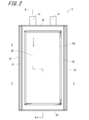
- FIG. 2 is a front view showing the appearance of the entire electrochemical cell
- FIG. 3 is a cross-sectional view of the electrochemical cell as viewed from the cutting plane line BB of FIG. 4 is a cross-sectional view seen from the cutting plane line CC of FIG. 2
- FIG. 5 is a front view showing a single cell of the electrochemical cell of FIG. 2
- FIG. 6 is a cutting plane line D- of FIG. It is sectional drawing seen from D.
- the electrochemical cell 1 of the present embodiment has an outer surface having a power generation element 2 that can be charged and discharged by an electrochemical reaction, an inner container 3 that houses the power generation element 2, and a first sheet portion 4a and a second sheet portion 4b.
- the inner container 3 is housed in a state of being located between the first sheet portion 4a and the second sheet portion 4b, and the peripheral edge portions 4a1 and the second sheet portion 4b of the first sheet portion 4a are accommodated.
- a portion 4b1 includes an outer container 4 that is heat-sealed. The inner container 3 and the outer container 4 are joined to each other.
- the inner container 3 and the outer container 4 are composed of a multilayer film having a thermosetting resin layer in the innermost layer.
- the power generation element 2, the inner container 3 and the outer container 4 are formed in a rectangular plate shape.
- the inner container 3 and the outer container 4 are connected to the outside of the region surrounding the power generation element 2 of the inner container 3.
- the portion 61 and the portion 62 surrounding the outerly connected portion 61 of the inner container 3 of the outer container 4 are joined.
- the inner container 3 is made of, for example, a base layer 17a made of a polyethylene terephthalate (PET) film and polyethylene laminated on one surface of the base layer 17a as a thermosetting resin layer of the innermost layer by a method such as coating. It is formed by a multilayer film 17 including an adhesive layer 17b having (PE). Further, the outer container 4 has an outer coating layer having a base layer 18a having a metal film such as aluminum, aluminum alloy or stainless steel, and a synthetic resin laminated on one surface of the base layer 18a, for example, polyamide (trade name: nylon). It is formed of a multilayer film 18 including 18b and an inner coating layer 18c made of, for example, polypropylene (PP), which is laminated on the other surface of the base layer 18a.
- PP polypropylene
- two multilayer films 17 are placed facing each other with the adhesive layer 17b inside, and the power generation element 2 is arranged between the two multilayer films 17, and the power generation elements 2 of these multilayer films 17 are placed outside from the power generation element 2.
- the adhesive layers 17b of each multilayer film 17 are joined to form a single cell 11 in which the power generation element 2 is hermetically sealed.
- a plurality of single cells 11 are laminated in the same direction to form a single cell laminated body 10.
- each multilayer film 18 is placed facing each other with the inner coating layer 18c inside, and the single-cell laminate 10 is arranged between the two multilayer films 18, and the single-cell laminates of these multilayer films 18 are arranged.
- the side edges on both sides of each single cell 11 are arranged between the side edges extending along two parallel sides of the peripheral edge protruding outward from the body 10 to form a laminated portion.
- the joint portion C1 is sandwiched by a heat seal machine, and each inner coating layer 18c of the outer container 4 and the base layer 17a of each inner container 3 arranged on the outermost side are joined by heat seal. It is fixed.
- joint portion C2 of the remaining side edge portions extending along the two parallel sides forming the opposite sides of the multilayer film 18 does not intervene the side edge portion of each single cell 11, and the inner coating layer of each multilayer film 18 is not interposed.
- the 18c are joined by heat sealing and airtightly sealed.
- the joint strength P1 of the joint portion C1 between the outer container 4 and the inner container 3 is smaller than the joint strength P2 of the joint portion C2 between the first sheet portion 4a and the second sheet portion 4b of the outer container 4 (P1 ⁇ P2). ..
- the joint portion C1 between the outer container 4 and the inner container 3 is formed from the joint portion C2 between the first sheet portion 4a and the second sheet portion 4b of the outer container 4. Is easy to come off first.
- the joint portion C1 is disengaged, the volume of the outer container 4 is increased by the area of the joint portion C1, and the joint portion C2 can be prevented from being disengaged by the gas.
- the single cell laminate 10 is maintained in a state of being sealed in the outer container 4, and is configured to reduce the risk of problems such as popping out of each single cell 11 and leakage of the electrolytic solution. There is.
- the joint strength P1 and the joint strength P2 may be measured according to, for example, the test method of JIS Z0238 (1998).
- the joint strength P1 and the joint strength P2 may be compared according to the values obtained as a result.
- joint portion C1 and the joint portion C2 may be formed by a heat seal machine, or may be formed by using, for example, a joint member.
- the power generation element 2 is a separator located between the positive electrode plate 12a having the positive electrode active material and the positive electrode current collector, the negative electrode plate 12b having the negative electrode active material and the negative electrode current collector, and the positive electrode plate 12a and the negative electrode plate 12b. It has a partition wall portion 12c, which is also called. It has terminal portions 13a and 13b that are connected to the positive electrode plate 12a and the negative electrode plate 12b, respectively, and are sandwiched by the inner container 3 and the outer container 4 with their tip portions protruding outward.
- the electrochemical cell module accommodates the plurality of electrochemical cells 1 described above, a current collecting member 40 (see FIG. 7 described later) for electrically connecting each electrochemical cell, and a plurality of electrochemical cells 1. It includes a housing 50 (see FIG. 7 described later).
- the electrochemical cell 1 of the present embodiment includes a single cell laminate 10 and an outer container 4.
- the single cell laminate 10 is a stack of a plurality of single cells 11.
- the single cell 11 has a plate shape and is a member of the smallest unit that functions as a battery in the electrochemical cell 1.
- the single cell 11 has a main surface 11a and the other main surface 11b on the opposite side of the main surface 11a.
- the shape of the single cell 11 when viewed from the stacking direction (horizontal direction in FIG. 3) of the single cell laminated body 10 may be, for example, a rectangular shape, a square shape, a circular shape, an elliptical shape, or the like. It may be in shape.
- the single cell 11 has a substantially rectangular shape when viewed from the stacking direction.
- the dimensions of the single cell 11 when viewed from the stacking direction are, for example, a long side length of 50 mm to 500 mm and a short side length of 50 mm to 300 mm.
- the thickness of the single cell 11 in the stacking direction is, for example, 0.1 mm to 2 mm.
- the single cell 11 has a power generation element 2, an inner container 3, a positive electrode terminal 14, and a negative electrode terminal 15.
- the power generation element 2 is a member for storing and releasing an electric charge by utilizing an electrochemical reaction.
- the power generation element 2 has, for example, a positive electrode plate 12a, a negative electrode plate 12b, and a partition wall portion 12c located between the positive electrode plate 12a and the negative electrode plate 12b.
- the power generation element 2 can exchange cations and anions between the positive electrode plate 12a and the negative electrode plate 12b via the partition wall portion 12c.
- the power generation element 2 can supply electric power to the external device by electrically connecting the positive electrode plate 12a and the negative electrode plate 12b to the external device.
- the positive electrode plate 12a and the negative electrode plate 12b are, for example, electrochemically active substances.
- the positive electrode plate 12a and the negative electrode plate 12b may have, for example, an active substance and an electrolytic solution.
- an electrolytic solution for example, a solvent or a solvent mixture to which a salt is added can be used.
- the positive electrode plate 12a is, for example, nickel-cobalt-aluminum-based lithium composite oxide (NCA), spinel-based lithium manganate (LMO), lithium iron phosphate (LFP), lithium cobalt oxide (LCO), nickel-cobalt-manganese-based lithium composite oxidation. It may contain one species selected from the group of objects (NCM) and the like.
- the positive electrode plate 12a may contain a solid compound known to those skilled in the art, which is used in, for example, a nickel hydrogen battery, a nickel cadmium battery, and the like.
- the positive electrode plate 12a may contain, for example, one selected from LiCoO 2 , Mg-doped LiCoO 2 , LiNiO 2, and the like.
- the negative electrode plate 12b may contain one selected from carbon-based materials such as graphite, hard carbon, soft carbon, carbon nanotubes, and graphene.
- the negative electrode plate 12b may contain, for example, one selected from titanium-based oxides such as lithium titanate and titanium dioxide.
- the negative electrode plate 12b may contain, for example, one selected from transition metal compounds containing iron, cobalt, copper, manganese, nickel and the like.
- the electrolytic solution may be, for example, a solvent to which a lithium salt is added.
- the lithium salt used in the electrolytic solution include LiPF 6 , LiBF 4 , LiFSI, LiClO 4, and the like.
- the solvent used in the electrolytic solution include propylene carbonate (PC), ethylene carbonate (EC), dimethyl carbonate (DMC), dimethoxyethane (DME), diethyl carbonate (DEC), tetrahydrofuran (THF), and triethylene glycol dimethyl ether. (Triglime), ⁇ -butyrolactone (GBL) and the like.
- the partition wall portion 12c is a member that reduces the possibility that the positive electrode plate 12a and the negative electrode plate 12b are short-circuited.
- the partition wall portion 12c may have, for example, fine pores through which cations and anions pass.
- a porous insulating material can be used as the partition wall portion 12c. Examples of the porous insulating material used in the partition wall portion 12c include polyolefin, polyvinyl chloride and the like.
- the shape of the power generation element 2 when viewed from the stacking direction may be, for example, a rectangular shape, a square shape, a circular shape, an elliptical shape, or any other shape.
- the power generation element 2 has a rectangular shape when viewed from the stacking direction.
- the length of the long side is 50 mm to 500 mm
- the length of the short side is 50 mm to 300 mm.
- the thickness of the power generation element 2 in the stacking direction is, for example, 0.1 mm to 2 mm.
- the plurality of single cells 11 are electrically connected in parallel. As a result, the capacity of the electrochemical cell module can be increased.
- the plurality of single cells 11 may be electrically connected in series. In this case, the output voltage of the electrochemical cell module can be increased.
- the inner container 34 is a member for electrically insulating the power generation element 2 from the external environment and protecting the power generation element 2 from the external environment.
- the inner container 3 covers the entire power generation element 2 and houses the power generation element 2.
- the inner container 3 has, for example, a flat bag shape.
- the inner container 3 is formed by joining two laminated films, for example.
- the inner container 3 may be formed, for example, by forming a laminated film into a flat bag shape.
- the shape of the inner container 3 when viewed from the stacking direction may be, for example, a rectangular shape, a square shape, or any other shape. In the present embodiment, for example, as shown in FIG. 4, the inner container 3 has a rectangular shape when viewed from the stacking direction.
- the inner container 3 has, for example, an insulating material. As a result, the possibility that the external environment and the power generation element 2 are short-circuited via the inner container 3 can be reduced, so that the power generation element 2 can be protected from the external environment.
- the inner container 3 has, for example, a resin material.
- the resin material for example, polyethylene terephthalate, polyethylene, or the like can be used.
- the inner container 3 may have a multi-layer structure, for example.
- the inner container 3 may have, for example, a thermosetting resin material and a heat-resistant resin material.
- the thermosetting resin material is, for example, a resin material having a melting temperature of less than 150 ° C.
- the thermosetting resin material for example, polyethylene, polypropylene, or the like can be used.
- the heat-resistant resin material is, for example, a resin material having a melting temperature of 150 ° C. or higher and 300 ° C. or lower.
- As the heat-resistant resin material for example, polyethylene terephthalate or polyethylene naphthalate can be used.
- the inner container 3 may be formed by, for example, laminating two laminated films having a thermosetting resin material and a heat-resistant resin material facing each other.
- the laminated film may have, for example, a rectangular shape having a long side and a short side.
- the two laminated films may be joined by shifting in the short side direction.
- the two laminated films may have an extension portion that does not overlap with each other.
- the length of the short side of the extension portion can be, for example, 5 mm to 50 mm.
- thermosetting resin material of the extension portion By joining the thermosetting resin material of the extension portion and the thermosetting resin material of the outer container 4, the bonding strength between the inner container 3 and the outer container 4 can be improved. As a result, the possibility of misalignment can be reduced, and the reliability of the electrochemical cell can be improved.
- the inner containers 3 may be joined to each other by joining the thermosetting resin layer of the extension portion of one inner container 3 and the heat-resistant resin layer of the extension portion of the other inner container 3. As a result, the inner containers 3 are fixed to each other, and the possibility that the inner container 3 is displaced in the outer container 4 can be further reduced.
- the positive electrode terminal 14 and the negative electrode terminal 15 are members for taking out the electricity stored in the power generation element 2 to the outside of the inner container 3.
- the positive electrode terminal 14 and the negative electrode terminal 15 are located from the inside of the inner container 3 to the outside of the inner container 3.
- the positive electrode terminal 14 is electrically connected to the positive electrode plate 12a and electrically insulated from the negative electrode plate 12b and the negative electrode terminal 15.
- the positive electrode terminal 14 is made of, for example, a metal material. Examples of the metal material used for the positive electrode terminal 14 include aluminum and an aluminum alloy.
- the positive electrode terminal 14 has a first positive electrode terminal portion 14a located inside the inner container 3 and a second positive electrode terminal portion 14b located outside the inner container 3.
- the first positive electrode terminal portion 14a may be in contact with the positive electrode plate 12a.
- the first positive electrode terminal portion 14a may be located between the inner container 3 and the positive electrode plate 12a.
- the second positive electrode terminal portion 14b is connected to the connection terminal of the electrochemical cell 1.
- the second positive electrode terminal portion 14b may have, for example, a rectangular plate shape, a square plate shape, or the like, or may have any other shape. In the present embodiment, for example, as shown in FIG. 5, the second positive electrode terminal portion 14b has a rectangular shape when viewed from the stacking direction.
- the dimensions of the second positive electrode terminal portion 14b when viewed from the stacking direction are, for example, a long side length of 30 mm to 100 mm and a short side length of 10 mm to 100 mm.
- the thickness of the second positive electrode terminal portion 14b in the stacking direction is, for example, 3 ⁇ m to 30 ⁇ m.
- the negative electrode terminal 15 is electrically connected to the negative electrode plate 12b and is electrically insulated from the positive electrode plate 12a and the positive electrode terminal 14.
- the negative electrode terminal 15 is made of, for example, a metal material. Examples of the metal material used for the negative electrode terminal 15 include copper and a copper alloy.
- the negative electrode terminal 15 has a first negative electrode terminal portion 15a located inside the inner container 3 and a second negative electrode terminal portion 15b located outside the inner container 3.
- the first negative electrode terminal portion 15a may be in contact with the negative electrode plate 12b.
- the first negative electrode terminal portion 15a may be located between the inner container 3 and the negative electrode plate 12b.
- the second negative electrode terminal portion 15b is connected to the connection terminal of the electrochemical cell 1.
- the second negative electrode terminal portion 15b may have, for example, a rectangular plate shape, a square plate shape, or the like, or may have any other shape. In the present embodiment, for example, as shown in FIG. 5, the second negative electrode terminal portion 15b has a rectangular shape when viewed from the stacking direction.
- the dimensions of the second negative electrode terminal portion 15b when viewed from the stacking direction are, for example, a long side length of 30 mm to 100 mm and a short side length of 10 mm to 100 mm.
- the thickness of the second negative electrode terminal portion 15b in the stacking direction is, for example, 3 ⁇ m to 30 ⁇ m.
- the second positive electrode terminal portion 14b and the second negative electrode terminal portion 15b may extend outward from one side of the inner container 3 when viewed from the stacking direction, for example, as shown in FIG.
- the second positive electrode terminal portion 14b and the second negative electrode terminal portion 15b may extend outward from different sides of the inner container 3 when viewed from the stacking direction.
- the outer container 4 is a member for protecting the single cell laminated body 10 from the external environment.
- the external environment is, for example, oxygen and moisture in the air.
- the outer container 4 covers the entire single-cell laminated body 10 and houses the single-cell laminated body 10.
- the outer container 4 may have, for example, a cylindrical shape, a bag shape, or the like, or may have any other shape.
- the outer container 4 may be, for example, one in which two members are joined to form a bag, or one member may be in the shape of a bag.
- the shape of the outer container 4 when viewed in the stacking direction may be, for example, a rectangular shape, a square shape, or any other shape. In the present embodiment, for example, as shown in FIG.
- the outer container 4 has a rectangular shape when viewed in the stacking direction. Further, the outer container 4 is arranged so that the long side direction and the short side direction of the outer container 4 substantially coincide with the long side direction and the short side direction of the single cell laminated body 10 when viewed in the stacking direction. ing.
- the dimensions of the outer container 4 when viewed from the stacking direction are, for example, a long side length of 50 mm to 600 mm and a short side length of 50 mm to 400 mm. Further, the thickness of the portion of the outer container 4 that overlaps with the single cell laminated body 10 when viewed in the laminating direction is, for example, 50 ⁇ m to 300 ⁇ m.
- the electrochemical cell 1 is provided with a connection terminal 30.
- the connection terminal 30 is a member for taking out the electricity stored in the single cell laminate 10 to the outside of the outer container 4.
- the connection terminal 30 includes a first connection terminal 31 and a second connection terminal 32.
- the first connection terminal 31 and the second connection terminal 32 are located from the inside of the outer container 4 to the outside of the outer container 4.
- a plurality of positive electrode terminals 14 connected to each other are joined to a portion of the first connection terminal 31 located inside the outer container 4.
- a plurality of negative electrode terminals 15 connected to each other are connected to a portion of the second connection terminal 32 located inside the outer container 4.
- the first connection terminal 31 and the second connection terminal 32 may be made of, for example, a metal material. Examples of the metal material used for the first connection terminal 31 and the second connection terminal 32 include copper, copper alloy, aluminum, and aluminum alloy.
- the outer container 4 has, for example, an insulating material.
- an insulating material for example, a resin material such as polyethylene terephthalate or polyethylene can be used.
- the outer container 4 has, for example, a multi-layer structure.
- the outer container 4 may have, for example, a three-layer structure.
- the outer container 4 may have, for example, a first insulating layer, a moisture-proof layer, and a second insulating layer.
- the moisture-proof layer is located between the first insulating layer and the second insulating layer.
- the moisture-proof layer may be covered with a first insulating layer and a second insulating layer.
- the moisture-proof layer may be in direct contact with the first insulating layer and the second insulating layer.
- the first insulating layer may be the outermost layer in the outer container 4 having a three-layer structure.
- the first insulating layer may have, for example, a resin material such as polyethylene terephthalate or polyethylene naphthalate.
- the moisture-proof layer is a member that prevents oxygen, moisture, etc. that have permeated the first insulating layer from reaching the second insulating layer.
- the moisture-proof layer may have a metal material such as copper, a copper alloy, aluminum, or an aluminum alloy.
- the second insulating layer may have a resin material such as polyethylene or polypropylene.
- the outer container 4 may be provided with a liquid layer 21 that transmits external pressure to the single cell 11.
- the liquid layer 21 is located between two adjacent single cells 11.
- the liquid layer 21 may be in direct contact with both of two adjacent single cells 11.
- the liquid layer 21 can be located inside the recesses even when the recesses are present on the main surface 11a and the other main surface 11b of the single cell 11, so that the two adjacent single cells 11 are adjacent to each other. Pressure can be applied evenly to.
- the two adjacent single cells 11 can carry out a charge / discharge reaction without making the interfacial resistance non-uniform, so that they are less likely to deteriorate and the life of the electrochemical cell 1 can be extended.
- the liquid layer 21 may be located between the single cell laminate 10 and the outer container 4, for example, as shown in FIGS. 2 and 3. As a result, the single-cell laminated body 10 is less likely to be displaced in the outer container 4, so that the joint portion between the connection terminal 30, the positive electrode terminal 14 and the negative electrode terminal 15 is less likely to be damaged.
- the liquid layer 21 may be, for example, an organic solvent.
- the organic solvent used for the liquid layer 21 include ethylene carbonate and ⁇ -butyrolactone.
- the liquid layer 21 may be a low molecular weight polymer material having fluidity such as polyethylene oxide.
- the liquid layer 21 may be, for example, a silicon-based polymer material such as silicone.
- the liquid layer 21 may have a water-absorbent material such as a water-absorbent polymer.
- a water-absorbent material such as a water-absorbent polymer.
- the liquid layer 21 can absorb the water that has penetrated into the outer container 4, so that it is difficult for the water to penetrate into the single cell 11, and the life of the electrochemical cell 1 can be extended. it can.
- the water-absorbent polymer used for the liquid layer 21 include polyacrylonitrile.
- the liquid layer 21 may have an inorganic material such as a porous filler.
- a porous filler As a result, the liquid layer 21 can absorb the water that has penetrated into the outer container 4, so that it is difficult for the water to penetrate into the single cell 11, and the life of the electrochemical cell 1 can be extended. it can.
- the porous filler used in the liquid layer 21 for example, zeolite or the like can be used.
- the liquid layer 21 may have a metal filler that reacts with oxygen and water.
- oxygen and water that have entered the outer container 4 react with the metal filler to make it difficult for the oxygen and water to penetrate into the single cell 11, and the life of the electrochemical cell 1 can be extended.
- the metal filler used in the liquid layer 21 include iron, copper, copper alloys, aluminum, and aluminum alloys.
- the liquid layer 21 may be made of a material having a higher thermal conductivity than the electrolytic solution of the power generation element 2. As a result, the heat generated in the single cell 11 is easily transferred to the liquid layer 21, so that the heat is less likely to be accumulated in the single cell 11. Thereby, the life of the electrochemical cell 1 can be improved.
- the liquid layer 21 may be a material having a higher viscosity than the electrolytic solution of the power generation element 2.
- FIG. 7 is an exploded perspective view showing an example of an embodiment of the electrochemical cell module of the present disclosure.
- the same reference numerals will be added to the parts corresponding to the above-described embodiments, and duplicate description will be omitted.
- the electrochemical cell module of the present embodiment includes the plurality of electrochemical cells 1 described in the above-described embodiment, a current collecting member 40, and a housing 50.
- the plurality of electrochemical cells 1 are laminated with each other in a predetermined second direction.
- the plurality of electrochemical cells 1 are laminated so that their outer shapes are substantially the same when viewed from the second direction, forming the single cell laminate 10.
- the single-cell laminate 10 has a substantially rectangular parallelepiped shape, and the first connection terminal 31 and the second connection terminal 32 of the plurality of electrochemical cells 1 are from the upper surface 2a of the single-cell laminate 10. It is protruding.
- the current collecting member 40 is a member that electrically connects a plurality of electrochemical cells 1 to each other.
- the current collecting member 40 may electrically connect a plurality of electrochemical cells 1 in parallel. That is, the current collecting member 40 may electrically connect the first connection terminals 31 of the plurality of electrochemical cells 1 to each other and electrically connect the second connection terminals 32 of the plurality of electrochemical cells 1 to each other. ..
- the capacity of the electrochemical cell module can be increased.
- the current collecting member 40 may electrically connect the first connection terminal 31 and the second connection terminal 32 of the plurality of electrochemical cells 1 so that the plurality of electrochemical cells 1 are electrically connected in series. Good. This makes it possible to increase the voltage of the electrochemical cell module.
- the housing 50 is a member for accommodating the single cell laminate 10 (that is, a plurality of electrochemical cells 1) and protecting the single cell laminate 10 from the external environment.
- the housing 50 may be a member for protecting the single cell laminated body 10 from an external force received from the external environment.
- the housing 50 is, for example, as shown in FIG. 6, a rectangular parallelepiped box body having one open side.
- the housing 50 may be formed, for example, by forming one member into a rectangular parallelepiped shape having one side open.
- the housing 50 may be formed by joining two or more members, for example.
- the housing 50 may have, for example, a metal material. As a result, the rigidity of the housing 50 is increased, and it is possible to make it difficult for the external force received from the external environment to be transmitted to the single cell laminated body 10. As a result, the single cell laminated body 10 can be protected from the external environment.
- the metal material used for the housing 50 for example, aluminum, stainless steel, or the like may be used. As a result, the heat generated in the single cell laminate 10 is easily transferred to the housing 50, so that the heat staying in the single cell laminate 10 is reduced, and the electrochemical cell 1 and the electrochemical cell module including the same are reduced. The life can be extended.
- the housing 50 may have, for example, a plurality of members.
- the plurality of members may include, for example, two main face plates 51, two side plate 52, and a bottom plate 53.
- the main face plate 51, the side plate 52, and the bottom plate 53 may contain a metal material and a resin material.
- the two main face plates 51 are members for protecting the end faces 2b and 2c of the single cell laminated body 10 in the second direction.
- the two main face plates 51 face the end faces 2b and 2c of the single cell laminated body 10, respectively.
- the main face plate 51 may have a rectangular shape when viewed from the second direction. In this case, the main face plate 51 may have, for example, a long side of 200 mm to 600 mm and a short side of 50 mm to 300 mm. Further, the main face plate 51 may have a thickness of, for example, 0.5 mm to 5 mm.
- the main face plate 51 may be made of, for example, a metal material.
- the metal material used for the main face plate 51 include aluminum, aluminum alloy, stainless steel and the like.
- the main face plate 51 may be made of, for example, a resin material.
- the resin material used for the main face plate 51 include a heat-resistant resin material such as polyethylene terephthalate (PET).
- PET polyethylene terephthalate
- the two side plates 52 are members of the single cell laminated body 10 for protecting the side surfaces 2d and 2e connected to the upper surface 2a and along the second direction.
- the two side plates 52 face the side surfaces 2d and 2e of the single cell laminated body 10, respectively.
- the side plate 52 may be in contact with at least one of the side surfaces 2d and 2e of the single cell laminated body 10. As a result, the heat generated in the electrochemical cell 1 is easily transferred to the outside through the side plate 52, so that the life of the electrochemical cell 1 can be extended.
- the electrochemical cell module of the present embodiment includes the electrochemical cell 1 of the above embodiment, so that the side plate 52 is in contact with at least one of the side surfaces 2d and 2e of the single cell laminate 10.
- the deformation of the outer container 4 can be suppressed and the misalignment of the single cell laminate 10 in the outer container 4 can be reduced, the possibility that the durability of the electrochemical cell 1 is lowered can be reduced. it can.
- the side plate 52 may have a rectangular shape when viewed from a direction perpendicular to the side surfaces 2d and 2e of the single cell laminated body 10.
- the side plate 52 may have, for example, a long side of 200 mm to 600 mm and a short side of 50 mm to 300 mm.
- the side plate 52 may have a thickness of, for example, 0.5 mm to 5 mm.
- the side plate 52 may be made of, for example, a metal material.
- the metal material used for the side plate 52 include aluminum, aluminum alloy, stainless steel and the like.
- the side plate 52 may be made of, for example, a resin material.
- the resin material used for the side plate 52 include a heat-resistant resin material such as polyethylene terephthalate (PET).
- PET polyethylene terephthalate
- the bottom plate 53 is a member for protecting the lower surface 2f on the side opposite to the upper surface 2a of the single cell laminated body 10.
- the bottom plate 53 may be formed by bending a part of the main face plate 51 or the side plate 52.
- the bottom plate 53 may be in contact with the lower surface 2f of the single cell laminated body 10 on the side opposite to the upper surface 2a. As a result, the heat generated in the electrochemical cell 1 is easily transferred to the outside through the bottom plate 53, so that the life of the electrochemical cell 1 can be extended.
- the electrochemical cell module of the present embodiment includes the electrochemical cell 1 of the present embodiment, so that even when the bottom plate 53 is in contact with the lower surface 2f of the single cell laminate 10, the outer container is provided. Since the deformation of 4 can be suppressed and the misalignment of the single cell laminate 10 in the outer container 4 can be reduced, the possibility that the durability of the electrochemical cell 1 is lowered can be reduced.
- the bottom plate 53 may have a rectangular shape when viewed from a direction perpendicular to the lower surface 2f of the single cell laminated body 10.
- the bottom plate 53 may have, for example, a long side of 200 mm to 600 mm and a short side of 50 mm to 300 mm.
- the bottom plate 53 may have a thickness of, for example, 0.5 mm to 5 mm.
- the bottom plate 53 may be made of, for example, a metal material.
- the metal material used for the bottom plate 53 include aluminum, aluminum alloy, stainless steel and the like.
- the bottom plate 53 may be, for example, a resin material.
- the resin material used for the bottom plate 53 include a heat-resistant resin material such as polyethylene terephthalate (PET).
- PET polyethylene terephthalate
- the single cell laminated body 10 may be held in the housing 50 by pressing the end faces 2b and 2c in the second direction.
- the single cell laminated body 10 may be pressed and held by the pressing plate 54 and the elastic body 55.
- the pressing plate 54 for example, a metal material may be used. As a result, the heat generated from the electrochemical cell 1 can be easily transferred to the outside. As a result, the life of the electrochemical cell 1 can be extended.
- the metal material used for the pressing plate 54 include aluminum, aluminum alloy, stainless steel and the like.
- the pressing plate 54 for example, an insulating resin material may be used. As a result, the electrochemical cell 1 and the external environment can be electrically insulated, so that the possibility of a short circuit between the electrochemical cell 1 and the external environment can be reduced.
- the resin material used for the pressing plate 54 include thermosetting resins such as epoxy resin, phenol resin, and melamine resin.
- the pressing plate 54 for example, a resin material and a metal material may be used.
- the resin material may be used, for example, in the portion of the pressing plate 54 that comes into contact with the single cell laminate 10.
- the electrochemical cell 1 and the pressing plate 54 can be electrically insulated from each other.
- the possibility that the electrochemical cell 1 and the external environment are short-circuited can be reduced.
- a metal material for the pressing plate 54 it is possible to prevent the pressing plate from being damaged.
- the elastic body 55 is located between the pressing plate 54 and the main surface plate 51 of the housing 50.
- the elastic body 55 is provided to apply pressure to the electrochemical cell 1 by applying pressure to the pressing plate 54.
- a spring can be used as the elastic body 55.
- the spring may be, for example, a spiral compression coil spring. Further, the spring may be, for example, a bent plate-shaped leaf spring.
- the spring may be made of, for example, a metallic material. Examples of the metal material used for the spring include spring steel, stainless steel, etc., which have a spring constant capable of exerting a counterforce against the inertial load of the single cell laminate 10 due to expected vibration, impact, etc., and are used. Materials that are weather resistant to the environment are used.
- the dimensions of the spring may be, for example, in the case of a spiral shape, the diameter may be 5 mm to 50 mm, the length may be 10 mm to 50 mm, and the pitch may be 1 mm to 10 mm.
- a plate-shaped rubber material may be used as the elastic body 55.
- the rubber material may have the same shape as the pressing plate 54, for example.
- the rubber material may be, for example, natural rubber or synthetic rubber.
- pressure may be applied to the end faces 2b and 2c in the second direction by the housing 50.
- the housing 50 may apply pressure by, for example, screwing the main face plate 51 and the side plate 52 so that the main face plate 51 presses the end faces 2b and 2c of the single cell laminate 10.
- the electrochemical cell module by providing the electrochemical cell 1, it is possible to provide an electrochemical cell module having excellent durability. Further, according to the electrochemical cell module, the highly rigid housing 50 makes it difficult for the external force received from the external environment to be transmitted to the electrochemical cell 1. Therefore, it becomes possible to provide an electrochemical cell module having further excellent durability.
- FIG. 8 is a partially enlarged cross-sectional view schematically showing the electrochemical cell of another embodiment of the present disclosure.
- the same reference numerals are given to the parts corresponding to the above-described embodiments, and duplicate description will be omitted.
- the electrochemical cell 1a of the present embodiment is located on the outer side of the two multilayer films 17 of the single cell 11 arranged on the outermost side (upper side and lower side in FIG. 1) of the single cell laminated body 10 in the stacking direction.
- the portion of the one multilayer film 17 located at the laminated portion is removed to expose the adhesive layer 17b, which is the thermosetting resin layer of the other multilayer film 17, toward the outside.
- the exposed adhesive layer 17b and the inner coating layer 18c which is a heat-adhesive resin layer of the outer container 4, are directly opposed to each other and bonded by ultrasonic bonding as described above to form a bonded portion C1a. ..
- the adhesive layer 17b of the multilayer film 17 constituting the inner container 3 and the inner coating layer 18c of the multilayer film 18 constituting the outer container 4 are bonded to the outer container 4 and the contents.
- the vessel 3 can be joined with a higher joining strength.
- the electrochemical cell system includes the electrochemical cell module of the above-described embodiment and a control unit that controls the electrochemical cell module.
- the control unit may be built in the electrochemical cell module as a control IC that protects the battery from overcharging / overdischarging.
- a protection circuit may be constructed as a program in the control IC.
- This protection circuit cuts off the current and forcibly stops the flow of the charging current when the battery voltage is preset and tries to exceed the battery voltage when fully charged. Further, when the battery voltage at the time of discharge becomes less than the preset dischargeable voltage, the discharge current is forcibly cut off. Furthermore, if such a protection circuit operates and the power supply is suddenly cut off, the equipment (electric power consumer) that was supplying power from the electrochemical cell module will be seriously hindered. When the battery voltage drops to the dischargeable voltage so that such a state does not occur, warning information such as "The battery is low. Please charge.” Is notified by image display and sound. It is configured to warn the user, save the data in a memory or the like in response to the warning signal at this time, and stop the operation.
- constant current charging For example, constant current charging, constant voltage charging, and full charge determination are executed in this order. Charging with a current of a certain magnitude (constant current charging) is performed, and constant current constant voltage (Constant Voltage Constant Current; CVCC) control that shifts from a constant current to a constant voltage is executed.
- CVCC Constant Voltage Constant Current
- the electrochemical cell of the present disclosure includes a power generation element that can be charged and discharged by an electrochemical reaction.
- the inner container that houses the power generation element and An outer container having a first sheet portion and a second sheet portion, wherein the inner container is housed in a state of being located between the first sheet portion and the second sheet portion, and the first sheet portion.
- An outer container in which the peripheral edge portion of the second sheet portion and the peripheral edge portion of the second sheet portion are joined is provided. The inner container and the outer container are joined to each other.
- the electrochemical cell module of the present disclosure includes the above-mentioned plurality of electrochemical cells and A current collector that electrically connects the plurality of electrochemical cells to each other, It is characterized by including a housing for accommodating the plurality of electrochemical cells.
- the electrochemical cell and the electrochemical cell module of the present disclosure since the inner container and the outer container are joined to each other, the electrochemical cell and the electrochemical cell that do not shift in the outer container even if vibration or the like acts.
- the electrochemical cell module used can be provided.
- the electrochemical cell having a high degree of freedom in manufacturing such as the size of the electrochemical cell, the joining position, the joining length, and the number of joining points, and the electrochemical cell using the same are used.
- Chemical cell modules can be provided.
Landscapes
- Chemical & Material Sciences (AREA)
- Chemical Kinetics & Catalysis (AREA)
- Electrochemistry (AREA)
- General Chemical & Material Sciences (AREA)
- Engineering & Computer Science (AREA)
- Manufacturing & Machinery (AREA)
- Microelectronics & Electronic Packaging (AREA)
- Sealing Battery Cases Or Jackets (AREA)
- Battery Mounting, Suspending (AREA)
Abstract
電気化学反応によって充放電可能な発電要素と、発電要素が収容される内容器と、第1シート部分と第2シート部分とを有する外容器であって、内容器が、第1シート部分と第2シート部分との間に位置した状態で収容され、第1シート部分の周縁部と第2シート部分の周縁部とが接合された外容器と、を備え、内容器と外容器とが接合されている。
Description
本開示は、電気化学セルおよび電気化学セルモジュールに関する。
従来技術の一例は、特許文献1に記載されている。
本開示の電気化学セルは、電気化学反応によって充放電可能な発電要素と、
前記発電要素が収容される内容器と、
第1シート部分と第2シート部分とを有する外容器であって、前記内容器が、前記第1シート部分と前記第2シート部分との間に位置した状態で収容され、前記第1シート部分の周縁部と前記第2シート部分の周縁部とが接合された外容器と、を備え、
前記内容器と前記外容器とが接合されていることを特徴とする。
前記発電要素が収容される内容器と、
第1シート部分と第2シート部分とを有する外容器であって、前記内容器が、前記第1シート部分と前記第2シート部分との間に位置した状態で収容され、前記第1シート部分の周縁部と前記第2シート部分の周縁部とが接合された外容器と、を備え、
前記内容器と前記外容器とが接合されていることを特徴とする。
また、本開示の電気化学セルモジュールは、前述の複数の電気化学セルと、
前記複数の電気化学セルを、互いに電気的に接続する集電部材と、
前記複数の電気化学セルを収容する筐体と、を備えていることを特徴とする。
前記複数の電気化学セルを、互いに電気的に接続する集電部材と、
前記複数の電気化学セルを収容する筐体と、を備えていることを特徴とする。
本開示の目的、特色、および利点は、下記の詳細な説明と図面とからより明確になるであろう。
本開示の電気化学セルおよびそれを用いる電気化学セルモジュールの基礎となる構成では、例えば特許文献1に記載されているように、電気化学セル本体を内部に密封収納する外装体が、内容器と外容器との二重構造とされ、内容器および外容器のそれぞれは、最内層に熱接着性樹脂層を有する積層体によって構成されている。
内容器は、積層体の最内層同士を重ね合わせて積層体周縁部をヒートシールすることによって、電気化学セル本体が内容器内部に密封収納されている。また、外容器は、積層体の最内層同士を重ね合わせて積層体周縁部をヒートシールすることによって、電気化学セル本体の内部に密封収納した内容器を外容器内部に密封収納されている。これらの内容器および外容器からは、正極および負極の金属端子が外部に突出しており、外容器の外部に電気化学セルの接続部が設けられている。
上記特許文献1に記載される本開示の基礎となる構成では、内容器と外容器とは互いに接合されていない。そのため、電気化学セルおよびその組立て体である電気化学セルモジュールの製造時の移動および出荷後の製品の運搬などによって、電気化学セルおよび電気化学セルモジュールが振動すると、外容器の内部で内容器に電気化学セルが収容された単セルの積層体がずれを生じ、そのような積層体のずれが発生しない電気化学セルおよび電気化学セルモジュールが求められている。
以下、図面を用いて本開示の実施形態に係る電気化学セルおよびそれを備える電気化学セルモジュールについて説明する。
図1は本開示の実施形態の一例の電気化学セルを模式的に示す一部の拡大断面図であり、図2の切断面線A-Aから見た断面を示す。図2は電気化学セル全体の外観を示す正面図であり、図3は図2の切断面線B-Bから見た電気化学セルの断面図である。図4は図2の切断面線C-Cから見た断面図であり、図5は図2の電気化学セルの単セルを示す正面図であり、図6は図5の切断面線D-Dから見た断面図である。
本実施形態の電気化学セル1は、電気化学反応によって充放電可能な発電要素2と、発電要素2が収容される内容器3と、第1シート部分4aと第2シート部分4bとを有する外容器4であって、内容器3が、第1シート部分4aと第2シート部分4bとの間に位置した状態で収容され、第1シート部分4aの周縁部4a1と第2シート部分4bの周縁部4b1とがヒートシールによってされた外容器4と、を備える。これらの内容器3と外容器4とは、互いに接合されている。
内容器3および外容器4は、最内層に熱接着性樹脂層を有する多層フィルムによって構成される。発電要素2、内容器3および外容器4は、長方形の板状に形成されている、内容器3と外容器4とは、内容器3の発電要素2を包囲している領域の外側に連なる部分61と、外容器4の内容器3における外側に連なる部分61を包囲している部分62と、が接合されている。
さらに詳しく述べると、内容器3は、例えば、ポリエチレンテレフタレート(PET)フィルムから成る基層17aと、この基層17aの一表面に最内層の熱接着性樹脂層として、コーティングなどの手法によって積層されるポリエチレン(PE)を有する接着層17bとを含む多層フィルム17によって形成される。また、外容器4は、アルミニウム、アルミニウム合金またはステンレス鋼などの金属膜を有する基層18aと、この基層18aの一表面に積層される合成樹脂、例えばポリアミド(商標名:ナイロン)を有する外部被覆層18bと、基層18aの他表面に積層される合成樹脂、例えばポリプロピレン(PP)から成る内部被覆層18cとを含む多層フィルム18によって形成される。
内容器3は、2枚の多層フィルム17を、接着層17bを内側にして対向させて発電要素2を2枚の多層フィルム17間に配置し、これらの多層フィルム17の発電要素2から外側に突出する周縁部をヒートシールなどの手法によって加熱加圧することによって、各多層フィルム17の接着層17bが接合され、気密に発電要素2が封止された単セル11が形成される。単セル11は、複数枚が向きを揃えて積層され、単セル積層体10が形成される。
外容器4は、2枚の多層フィルム18を、内部被覆層18cを内側にして対向させて単セル積層体10を2枚の多層フィルム18間に配置し、これらの多層フィルム18の単セル積層体10から外側に突出する周縁部の平行な2辺に沿って延びる各側縁部間に各単セル11の両側の側縁部をそれぞれ配置して積層部を形成する。これらの積層部は、接合部分C1がヒートシール機によって挟着され、ヒートシールによって外容器4の各内部被覆層18cと最も外側に配置されている各内容器3の基層17aとが接合されて固定される。また、多層フィルム18の対辺を成す平行な2辺に沿って延びる残りの各側縁部の接合部分C2は、各単セル11の側縁部は介在させず、各多層フィルム18の内部被覆層18c同士をヒートシールによって接合し、気密に封止する。
このような外容器4には、内部の電気化学反応によって発生した反応ガス、熱膨張した空気などの気体を排気するための孔径1mm程度のガス抜き孔19がヒートシール部の近くに形成されている。
外容器4と内容器3との接合部分C1の接合強度P1は、外容器4の第1シート部分4aと第2シート部分4bとの接合部分C2の接合強度P2よりも小さい(P1<P2)。これによって、外容器4内でガスが発生した際に、外容器4と内容器3との接合部分C1が、外容器4の第1シート部分4aと第2シート部分4bとの接合部分C2よりも先に外れやすくなる。その結果、接合部分C1が外れることで、接合部分C1で接合していた面積分だけ外容器4の容積が大きくなり、ガスによって接合部C2が外れにくくすることができる。その結果、単セル積層体10は外容器4に封止された状態に維持され、各単セル11の外部への飛び出し、電解液の漏出などの不具合の発生リスクが低くなるように構成されている。
ここで、接合強度P1および接合強度P2の測定については、例えば、JIS Z0238(1998)の試験方法に従って行ってもよい。その結果得られた値によって、接合強度P1および接合強度P2の比較を行ってもよい。
また、接合部分C1および接合部分C2は、ヒートシール機によって形成されてもよいし、例えば、接合部材を用いて形成されてもよい。
発電要素2は、正極活性物質および正極集電体を有する正極板12aと、負極活性物質および負極集電体を有する負極板12bと、正極板12aと負極板12bとの間に位置する、セパレータとも呼ばれる隔壁部12cと、を有する。正極板12aおよび負極板12bにそれぞれ接続され、内容器3と外容器4とによって先端部を外部に突出させた状態で挟持された端子部13a,13bを有する。
電気化学セルモジュールは、前述した複数の電気化学セル1と、各電気化学セルを互いに電気的に接続する集電部材40(後述の図7を参照)と、複数の電気化学セル1を収容する筐体50(後述の図7を参照)と、を備える。
本実施形態の電気化学セル1は、単セル積層体10と外容器4とを備える。単セル積層体10は、複数の単セル11を積層したものである。単セル11は、板状であり、電気化学セル1内で電池として機能する最小の単位の部材である。
単セル11は、主面11a、および主面11aとは反対側の他方主面11bを有する。単セル11は、単セル積層体10の積層方向(図3における左右方向)から見たときの形状が、例えば、矩形状、正方形状、円形状、楕円形状等であってもよく、その他の形状であってもよい。本実施形態では、例えば図5に示すように、単セル11は、積層方向から見たときに、略矩形状である。積層方向から見たときの単セル11の寸法は、例えば、長辺の長さが50mm~500mmであり、短辺の長さが50mm~300mmである。また、積層方向における単セル11の厚みは、例えば、0.1mm~2mmである。
単セル11は、発電要素2、内容器3、正極端子14および負極端子15を有する。発電要素2は、電気化学反応を利用して電荷を蓄え、放出するための部材である。発電要素2は、例えば、正極板12a、負極板12bおよび正極板12aと負極板12bとの間に位置する隔壁部12cを有している。発電要素2は、隔壁部12cを介して、正極板12aと負極板12bとの間で陽イオンおよび陰イオンを交換することができる。発電要素2は、正極板12aおよび負極板12bを外部装置と電気的に接続することによって、外部装置に電力供給することができる。
正極板12aおよび負極板12bは、例えば、電気化学的に活性な物質である。正極板12aおよび負極板12bは、例えば、活性物質および電解液を有していてもよい。電解液としては、例えば、溶剤または溶剤混合液に塩を加えたものを用いることができる。
正極板12aは、例えば、ニッケルコバルトアルミニウム系リチウム複合酸化物(NCA)、スピネル系マンガン酸リチウム(LMO)、リン酸鉄リチウム(LFP)、コバルト酸リチウム(LCO)、ニッケルコバルトマンガン系リチウム複合酸化物(NCM)等の群から選ばれた1種を含んでいてもよい。正極板12aは、例えば、ニッケル水素バッテリ、ニッケルカドミウムバッテリ等で用いられる、当業者にとって既知の固体化合物を含んでいてもよい。正極板12aは、例えば、LiCoO2、MgがドープされたLiCoO2、LiNiO2等から選ばれた1種を含んでいてもよい。
負極板12bは、例えば、黒鉛、ハードカーボン、ソフトカーボン、カーボンナノチューブ、グラフェン等の炭素系材料から選ばれた1種を含んでいてもよい。負極板12bは、例えば、チタン酸リチウム、二酸化チタン等のチタン系酸化物から選ばれた1種を含んでいてもよい。負極板12bは、例えば、鉄、コバルト、銅、マンガン、ニッケル等を含有する遷移金属化合物から選ばれた1種を含んでいてもよい。
電解液は、電気化学セルモジュールがリチウムイオン電池である場合、例えば、溶剤にリチウム塩を加えたものを用いることができる。電解液に用いられるリチウム塩としては、例えば、LiPF6、LiBF4、LiFSI、LiClO4等が挙げられる。電解液に用いられる溶剤としては、例えば、炭酸プロピレン(PC)、炭酸エチレン(EC)、炭酸ジメチル(DMC)、ジメトキシエタン(DME)、炭酸ジエチル(DEC)、テトラヒドロフラン(THF)、トリエチレングリコールジメチルエーテル(Triglyme)、γブチロラクトン(GBL)等が挙げられる。
隔壁部12cは、正極板12aと負極板12bとが短絡する可能性を低減する部材である。隔壁部12cは、例えば、陽イオンおよび陰イオンが通過するための微細な孔が開いていてもよい。隔壁部12cとしては、例えば、多孔質の絶縁材料を用いることができる。隔壁部12cで用いられる多孔質の絶縁材料としては、例えば、ポリオレフィン、ポリ塩化ビニル等が挙げられる。
発電要素2は、積層方向から見たときの形状が、例えば、矩形状、正方形状、円形状、楕円形状等であってもよく、その他の形状であってもよい。本実施形態では、例えば、発電要素2は、積層方向から見たときに、矩形状である。積層方向から見たときの発電要素2の寸法の一例としては、長辺の長さが50mm~500mmであり、短辺の長さが50mm~300mmである。また、積層方向における発電要素2の厚みは、例えば、0.1mm~2mmである。
本実施形態では、複数の単セル11は、電気的に並列に接続されている。これによって、電気化学セルモジュールの容量を大きくすることができる。なお、複数の単セル11は、電気的に直列に接続されていてもよい。この場合、電気化学セルモジュールの出力電圧を高めることができる。
内容器34は、外部環境から発電要素2を電気的に絶縁し、外部環境から発電要素2を保護するための部材である。内容器3は、発電要素2全体を覆い、発電要素2を収容している。内容器3は、例えば、扁平な袋形状である。内容器3は、例えば、2つのラミネートフィルムを接合して形成されている。内容器3は、例えば、ラミネートフィルムを扁平な袋形状にすることによって形成されていてもよい。内容器3は、積層方向から見たときの形状が、例えば、矩形状、正方形状等であってもよく、その他の形状であってもよい。本実施形態では、例えば図4に示すように、内容器3は、積層方向から見たときに、矩形状である。
内容器3は、例えば、絶縁材料を有している。これによって、外部環境と発電要素2とが内容器3を介して短絡する可能性を低減できるため、発電要素2を外部環境から保護することができる。内容器3は、例えば、樹脂材料を有している。樹脂材料としては、例えば、ポリエチレンテレフタレートまたはポリエチレン等を用いることができる。
内容器3は、例えば、多層構造を有していてもよい。内容器3は、例えば、熱接着性樹脂材料および耐熱性樹脂材料を有していてもよい。熱接着性樹脂材料は、例えば、融解する温度が150℃未満の樹脂材料である。熱接着性樹脂材料としては、例えば、ポリエチレンまたはポリプロピレン等を用いることができる。耐熱性樹脂材料は、例えば、融解する温度が150℃以上300℃以下の樹脂材料である。耐熱性樹脂材料としては、例えば、ポリエチレンテレフタレートまたはポリエチレンナフタレートを用いることができる。
また、内容器3は、例えば、熱接着性樹脂材料と耐熱性樹脂材料を有するラミネートフィルムを2枚向かい合わせて積層することで形成されていてもよい。このとき、ラミネートフィルムは、例えば、長辺と短辺とを有する長方形状であってもよい。また、2枚のラミネートフィルムを接合して内容器3を形成する際に、短辺方向にずらして、接合してもよい。言い換えると、2枚のラミネートフィルムを積層方向から見たときに、2枚のラミネートフィルムが互いに重ならない延長部を有していてもよい。延長部の短辺の長さは、例えば、5mm~50mmとすることができる。
延長部の熱接着性樹脂材料と外容器4の熱接着性樹脂材料とが接合されることで、内容器3と外容器4との接合強度を向上することができる。その結果、位置がずれてしまう可能性を低減することができ、電気化学セルの信頼性を向上させることができる。
また、一方の内容器3の延長部の熱接着性樹脂層と他方の内容器3の延長部の耐熱性樹脂層とが接合されることで、内容器3同士を接合してもよい。これにより、内容器3同士が固定され、外容器4内で内容器3が位置ずれする可能性をより低減することができる。
正極端子14および負極端子15は、発電要素2に蓄えられた電気を内容器3の外に取り出すための部材である。正極端子14および負極端子15は、内容器3内から内容器3外にかけて位置している。
正極端子14は、正極板12aに電気的に接続され、負極板12bおよび負極端子15から電気的に絶縁されている。正極端子14は、例えば、金属材料から成る。正極端子14に用いられる金属材料としては、例えば、アルミニウムまたはアルミニウム合金等が挙げられる。
正極端子14は、内容器3内に位置する第1正極端子部14a、および内容器3外に位置する第2正極端子部14bを有する。第1正極端子部14aは、正極板12aに接触していてもよい。第1正極端子部14aは、内容器3と正極板12aとの間に位置していてもよい。第2正極端子部14bは、電気化学セル1の接続端子に接続される。第2正極端子部14bは、例えば、矩形板状、正方形板状等の形状であってもよく、その他の形状であってもよい。本実施形態では、例えば図5に示すように、第2正極端子部14bは、積層方向から見たときに、矩形状である。積層方向から見たときの第2正極端子部14bの寸法は、例えば、長辺の長さが30mm~100mmであり、短辺の長さが10mm~100mmである。また、積層方向における第2正極端子部14bの厚みは、例えば、3μm~30μmである。
負極端子15は、負極板12bに電気的に接続され、正極板12aおよび正極端子14から電気的に絶縁されている。負極端子15は、例えば、金属材料から成る。負極端子15に用いられる金属材料としては、例えば、銅および銅合金が挙げられる。
負極端子15は、内容器3内に位置する第1負極端子部15a、および内容器3外に位置する第2負極端子部15bを有する。第1負極端子部15aは、負極板12bに接触していてもよい。第1負極端子部15aは、内容器3と負極板12bとの間に位置していてもよい。第2負極端子部15bは、電気化学セル1の接続端子に接続される。第2負極端子部15bは、例えば、矩形板状、正方形板状等の形状であってもよく、その他の形状であってもよい。本実施形態では、例えば図5に示すように、第2負極端子部15bは、積層方向から見たときに、矩形状である。積層方向から見たときの第2負極端子部15bの寸法は、例えば、長辺の長さが30mm~100mmであり、短辺の長さが10mm~100mmである。また、積層方向における第2負極端子部15bの厚みは、例えば、3μm~30μmである。
第2正極端子部14bと第2負極端子部15bとは、例えば図4に示すように、積層方向から見たときに、内容器3の1つの辺から外方に延びていてもよい。第2正極端子部14bと第2負極端子部15bとは、積層方向から見たときに、内容器3の相異なる辺から外方に延びていてもよい。
外容器4は、外部環境から単セル積層体10を保護するための部材である。外部環境とは、例えば、空気中の酸素および水分等である。外容器4は、単セル積層体10全体を覆い、単セル積層体10を収容している。外容器4は、例えば、円筒形状、袋形状等であってもよく、その他の形状であってもよい。外容器4は、例えば、2つの部材を接合して袋形状にしたものであってもよく、1つの部材を袋形状にしたものであってもよい。外容器4は、積層方向に見たときの形状が、例えば、矩形状、正方形状等であってもよく、その他の形状であってもよい。本実施形態では、例えば図1に示すように、外容器4は、積層方向に見たときに、矩形状である。また、外容器4は、積層方向に見たときに、外容器4の長辺方向および短辺方向が、単セル積層体10の長辺方向および短辺方向にそれぞれ略一致するように配置されている。積層方向から見たときの外容器4の寸法は、例えば、長辺の長さが50mm~600mmであり、短辺の長さが50mm~400mmである。また、外容器4の、積層方向に見たときに単セル積層体10と重なる部分の厚みは、例えば、50μm~300μmである。
電気化学セル1は、接続端子30を備えている。接続端子30は、単セル積層体10に蓄えられた電気を外容器4外に取り出すための部材である。接続端子30は、第1接続端子31および第2接続端子32を含んでいる。第1接続端子31および第2接続端子32は、外容器4内から外容器4外にかけて位置している。第1接続端子31の、外容器4内に位置する部分には、互いに接続された複数の正極端子14が接合されている。第2接続端子32の、外容器4内に位置する部分には、互いに接続された複数の負極端子15が接続されている。第1接続端子31および第2接続端子32は、例えば、金属材料であってもよい。第1接続端子31および第2接続端子32に用いられる金属材料としては、例えば、銅、銅合金、アルミニウム、アルミニウム合金等が挙げられる。
外容器4は、例えば、絶縁材料を有している。これによって、外部環境と単セル積層体10とが外容器4を介して短絡する可能性を低減することができるため、単セル積層体10を外部環境から保護することができる。絶縁材料としては、例えば、ポリエチレンテレフタレートまたはポリエチレン等の樹脂材料を用いることができる。
外容器4は、例えば、多層構造を有している。外容器4は、例えば、三層構造を有していてもよい。外容器4は、例えば、第1絶縁層、防湿層および第2絶縁層を有していてもよい。防湿層は、第1絶縁層と第2絶縁層との間に位置している。防湿層は、第1絶縁層および第2絶縁層によって覆われていてもよい。防湿層は、第1絶縁層および第2絶縁層に直接接触していてもよい。
第1絶縁層は、3層構造の外容器4における最外層であってもよい。第1絶縁層は、例えば、ポリエチレンテレフタレート、ポリエチレンナフタレート等の樹脂材料を有していてもよい。防湿層は、第1絶縁層を浸透してきた酸素、水分等が第2絶縁層に到達することを抑制する部材である。防湿層は、例えば、銅、銅合金、アルミニウム、アルミニウム合金等の金属材料を有していてもよい。第2絶縁層は、例えば、ポリエチレン、ポリプロピレン等の樹脂材料を有していてもよい。
外容器4内には、外部からの圧力を単セル11に伝える液体層21が設けられていてもよい。液体層21は、隣り合う2つの単セル11の間に位置している。液体層21は、隣り合う2つの単セル11の両方に直接接触していてもよい。これによって、液体層21は、単セル11の主面11aおよび他方主面11bに凹部が存在する場合であっても、該凹部の内部に位置することができるため、隣り合う2つの単セル11に圧力を均等に加えることができる。換言すると、隣り合う2つの単セル11は、界面抵抗が不均一になることなく充放電反応を行うことができるため、劣化しにくくなり、電気化学セル1の寿命を延ばすことができる。
液体層21は、例えば図2,3に示すように、単セル積層体10と外容器4との間に位置していてもよい。これによって、外容器4内で単セル積層体10が位置ずれしにくくなるため、接続端子30と正極端子14および負極端子15との接合部分が破損しにくくなる。
液体層21は、例えば、有機溶媒であってもよい。液体層21に用いられる有機溶媒としては、例えば、エチレンカーボネイト、γ-ブチロラクトン等が挙げられる。液体層21は、例えば、ポリエチレンオキシド等の流動性を有する低分子量の高分子材料であってもよい。液体層21は、例えば、シリコーン等のケイ素系の高分子材料であってもよい。
液体層21は、例えば、吸水性ポリマー等の吸水性材料を有していてもよい。これによって、液体層21が外容器4内に浸入してきた水分を吸収することができるため、単セル11の内部に水分が浸入しにくくすることができ、電気化学セル1の寿命を延ばすことができる。液体層21に用いられる吸水性ポリマーとしては、例えば、ポリアクリロニトリル等が挙げられる。
液体層21は、例えば、多孔質フィラー等の無機材料を有していてもよい。これによって、液体層21が外容器4内に浸入してきた水分を吸収することができるため、単セル11の内部に水分が浸入しにくくすることができ、電気化学セル1の寿命を延ばすことができる。液体層21に用いられる多孔質フィラーとしては、例えば、ゼオライト等を用いることができる。
液体層21は、酸素および水と反応する金属フィラーを有していてもよい。これによって、外容器4内に浸入した酸素および水が、金属フィラーと反応し、単セル11に浸入しにくくなり、電気化学セル1の寿命を延ばすことができる。液体層21に用いられる金属フィラーとしては、例えば、鉄、銅、銅合金、アルミニウム、アルミニウム合金等が挙げられる。
液体層21は、発電要素2の電解液と比較して、熱伝導率の高い材料から成っていてもよい。これによって、単セル11で発生した熱が液体層21に伝わりやすくなるため、単セル11に熱が蓄積されにくくなる。これによって電気化学セル1の寿命を向上することができる。
液体層21は、発電要素2の電解液と比較して、粘度が高い材料であってもよい。これによって、外容器4内で単セル積層体10が位置ずれしにくくなるため、粘着テープおよび接着剤などの別途の材料を用いることなく、接続端子30と正極端子14および負極端子15との接合部分を破損しにくくすることができる。これによって、電気化学セル1の寿命を延ばすことができる。
次に、本開示の実施形態に係る電気化学セルモジュールについて説明する。
図7は本開示の電気化学セルモジュールの実施形態の一例を示す分解斜視図である。なお、前述の実施形態と対応する部分に同一の参照符を付し、重複する説明は省略する。本実施形態の電気化学セルモジュールは、前述の実施形態で述べた複数の電気化学セル1と、集電部材40と、筐体50とを備える。
複数の電気化学セル1は、予め定められた第2方向に互いに積層されている。複数の電気化学セル1は、第2方向から見たときに、それらの外形が略一致するように積層され、単セル積層体10を構成している。単セル積層体10は、例えば図6に示すように、略直方体形状であり、複数の電気化学セル1の第1接続端子31および第2接続端子32は、単セル積層体10の上面2aから突出している。
集電部材40は、複数の電気化学セル1を互いに電気的に接続する部材である。集電部材40は、複数の電気化学セル1を電気的に並列に接続してもよい。すなわち、集電部材40は、複数の電気化学セル1の第1接続端子31同士を電気的に接続し、複数の電気化学セル1の第2接続端子32同士を電気的に接続してもよい。これによって、電気化学セルモジュールの容量を大きくすることができる。
集電部材40は、複数の電気化学セル1が電気的に直列に接続されるように、複数の電気化学セル1の第1接続端子31および第2接続端子32を電気的に接続してもよい。これによって、電気化学セルモジュールの電圧を高めることができる。
筐体50は、単セル積層体10(すなわち、複数の電気化学セル1)を収容し、外部環境から単セル積層体10を保護するための部材である。筐体50は、外部環境から受ける外力から単セル積層体10を保護するための部材であってもよい。本実施形態では、筐体50は、例えば図6に示すように、一面が開口した直方体形状の箱体である。筐体50は、例えば、1つの部材を一面が開口した直方体形状にすることによって形成されていてもよい。筐体50は、例えば、2つ以上の部材が結合されて形成されていてもよい。
筐体50は、例えば、金属材料を有していてもよい。これによって、筐体50の剛性が高くなり、外部環境から受ける外力を単セル積層体10に伝わりにくくすることができる。その結果、単セル積層体10を外部環境から保護することができる。筐体50に用いられる金属材料として、例えば、アルミニウム、ステンレス等が用いられてもよい。これによって、単セル積層体10で発生した熱が筐体50に伝わりやすくなるため、単セル積層体10に熱が滞留することを低減し、電気化学セル1およびそれを備える電気化学セルモジュールの寿命を延ばすことができる。
筐体50は、例えば、複数の部材を有していてもよい。複数の部材は、例えば、2つの主面板51と、2つの側面板52と、底面板53とを含んでいてもよい。主面板51、側面板52および底面板53は、金属材料および樹脂材料を含んでいてもよい。
2つの主面板51は、単セル積層体10の第2方向における端面2b,2cを保護するための部材である。2つの主面板51は、単セル積層体10の端面2b,2cにそれぞれ対向している。主面板51は、第2方向から見たときに、矩形状であってもよい。この場合、主面板51は、例えば、長辺が200mm~600mm、短辺が50mm~300mmであってもよい。また、主面板51は、例えば、厚みが0.5mm~5mmであってもよい。
主面板51は、例えば、金属材料であってもよい。主面板51に用いられる金属材料としては、例えば、アルミニウム、アルミニウム合金、ステンレス鋼等が挙げられる。これによって、電気化学セル1で発生した熱が、主面板51を介して、外部へ伝わりやすくなるため、電気化学セル1の寿命を延ばすことができる。
主面板51は、例えば、樹脂材料であってもよい。主面板51に用いられる樹脂材料としては、例えば、ポリエチレンテレフタレート(PET)等の耐熱性樹脂材料が挙げられる。これによって、電気化学セル1と外部環境とを電気的に絶縁することができるため、電気化学セル1と外部環境とが短絡する可能性を低減することができ、電気化学セル1の寿命を延ばすことができる。
2つの側面板52は、単セル積層体10の、上面2aに連なり且つ第2方向に沿った側面2d,2eを保護するための部材である。2つの側面板52は、単セル積層体10の側面2d,2eにそれぞれ対向している。
側面板52は、単セル積層体10の側面2d,2eの少なくとも一方に接触していてもよい。これによって、電気化学セル1で発生した熱が、側面板52を介して、外部へ伝わりやすくなるため、電気化学セル1の寿命を延ばすことができる。また、本実施形態の電気化学セルモジュールは、上記実施形態の電気化学セル1を備えることによって、側面板52が単セル積層体10の側面2d,2eの少なくとも一方に接触している場合であっても、外容器4の変形を抑制し、外容器4内における単セル積層体10の位置ずれを低減することができるため、電気化学セル1の耐久性が低下する可能性を低減することができる。
側面板52は、単セル積層体10の側面2d,2eに垂直な方向から見たときに、矩形状であってもよい。この場合、側面板52は、例えば、長辺が200mm~600mm、短辺が50mm~300mmであってもよい。また、側面板52は、例えば、厚みが0.5mm~5mmであってもよい。
側面板52は、例えば、金属材料であってもよい。側面板52に用いられる金属材料としては、例えば、アルミニウム、アルミニウム合金、ステンレス鋼等が挙げられる。これによって、電気化学セル1で発生した熱が、側面板52を介して、外部へ伝わりやすくなるため、電気化学セル1の寿命を延ばすことができる。
側面板52は、例えば、樹脂材料であってもよい。側面板52に用いられる樹脂材料としては、例えば、ポリエチレンテレフタレート(PET)等の耐熱性樹脂材料が挙げられる。これによって、電気化学セル1と外部環境とを電気的に絶縁することができるため、電気化学セル1と外部環境とが短絡する可能性を低減することができる。これによって、電気化学セル1の寿命を延ばすことができる。
底面板53は、単セル積層体10の上面2aとは反対側の下面2fを保護するための部材である。底面板53は、主面板51または側面板52の一部を折り曲げて形成されていてもよい。
底面板53は、単セル積層体10の、上面2aとは反対側の下面2fに接触していてもよい。これによって、電気化学セル1で発生した熱が、底面板53を介して、外部へ伝わりやすくなるため、電気化学セル1の寿命を延ばすことができる。また、本実施形態の電気化学セルモジュールは、本実施形態の電気化学セル1を備えることによって、底面板53が単セル積層体10の下面2fに接触している場合であっても、外容器4の変形を抑制し、外容器4内における単セル積層体10の位置ずれを低減することができるため、電気化学セル1の耐久性が低下する可能性を低減することができる。
底面板53は、単セル積層体10の下面2fに垂直な方向から見たときに、矩形状であってもよい。この場合、底面板53は、例えば、長辺が200mm~600mm、短辺が50mm~300mmであってもよい。また、底面板53は、例えば、厚みが0.5mm~5mmであってもよい。
底面板53は、例えば、金属材料であってもよい。底面板53に用いられる金属材料としては、例えば、アルミニウム、アルミニウム合金、ステンレス鋼等が挙げられる。これによって、電気化学セル1で発生した熱が、底面板53を介して、外部へ伝わりやすくなるため、電気化学セル1の寿命を延ばすことができる。
底面板53は、例えば、樹脂材料であってもよい。底面板53に用いられる樹脂材料としては、例えば、ポリエチレンテレフタレート(PET)等の耐熱性樹脂材料が挙げられる。これによって、電気化学セル1と外部環境とを電気的に絶縁することができるため、電気化学セル1と外部環境とが短絡する可能性を低減することができ、電気化学セル1の寿命を延ばすことができる。
単セル積層体10は、筐体50内で、第2方向における端面2b,2cが押圧されて保持されていてもよい。単セル積層体10は、押圧板54と弾性体55とによって押圧されて保持されていてもよい。
押圧板54として、例えば、金属材料が用いられてもよい。これによって、電気化学セル1から発生した熱を外部へ伝わりやすくすることができる。その結果、電気化学セル1の寿命を延ばすことができる。押圧板54に用いられる金属材料としては、例えば、アルミニウム、アルミニウム合金、ステンレス鋼等が挙げられる。
押圧板54として、例えば、絶縁性の樹脂材料が用いられてもよい。これによって、電気化学セル1と外部環境とを電気的に絶縁することができるため、電気化学セル1と外部環境とが短絡する可能性を低減することができる。押圧板54に用いられる樹脂材料としては、例えば、エポキシ樹脂、フェノール樹脂、メラミン樹脂等の熱硬化性樹脂が挙げられる。
押圧板54として、例えば、樹脂材料と金属材料とが用いられてもよい。樹脂材料は、例えば、押圧板54における単セル積層体10に接触する部分に用いられてもよい。これによって、電気化学セル1と押圧板54とを電気的に絶縁することができる。その結果、電気化学セル1と外部環境とが短絡する可能性を低減することができる。また、押圧板54に金属材料を用いることによって、押圧板を破損しにくくすることができる。
弾性体55は、押圧板54と筐体50の主面板51との間に位置している。弾性体55は、押圧板54に圧力を加えることによって、電気化学セル1に圧力を加えるために設けられている。弾性体55は、例えば、ばねを用いることができる。ばねは、例えば、らせん形状の圧縮コイルばねであってもよい。また、ばねは、例えば、曲がった板形状の板ばねであってもよい。ばねは、例えば、金属材料から成ってもよい。ばねに用いられる金属材料としては、例えば、ばね鋼、ステンレス鋼等が挙げられ、想定される振動、衝撃などによる単セル積層体10の慣性荷重に対する対抗力を発揮できるばね定数を有し、使用環境に対する耐候性を有する材料が用いられる。ばねの寸法は、例えば、螺旋形状の場合、直径が5mm~50mmであり、長さが、10mm~50mmであり、ピッチが1mm~10mmであってもよい。
弾性体55として、例えば、板状のゴム材料が用いられてもよい。ゴム材料は、例えば、押圧板54と同じ形状であってもよい。ゴム材料は、例えば、天然ゴムであってもよく、合成ゴムであってもよい。
また、単セル積層体10は、筐体50によって、第2方向における端面2b,2cに圧力が加えられていてもよい。筐体50は、例えば、主面板51と側面板52とをねじ止めすることによって、主面板51が単セル積層体10の端面2b,2cを押圧することによって圧力を加えてもよい。
電気化学セルモジュールによれば、電気化学セル1を備えることによって、耐久性に優れる電気化学セルモジュールを提供することができる。また、電気化学セルモジュールによれば、高剛性の筐体50によって、外部環境から受ける外力を電気化学セル1に伝わりにくくすることができる。このため、耐久性に一層優れる電気化学セルモジュールを提供することが可能になる。
図8は本開示の他の実施形態の電気化学セルを模式的に示す一部の拡大断面図である。なお、前述の実施形態と対応する部分には同一の参照符を付し、重複する説明は省略する。本実施形態の電気化学セル1aは、単セル積層体10の積層方向の最も外側(図1では上側および下側)に配置される単セル11の2枚の多層フィルム17のうち、外側に位置する一方の多層フィルム17の積層部に位置する部分を除去して、他方の多層フィルム17の熱接着性樹脂層である接着層17bを外側に向けて露出させる。この露出させた接着層17bと、外容器4の熱接着性樹脂層である内部被覆層18cとを直接対向させて、前述と同様な超音波接合によって接合されて接合部分C1aが形成されている。
このような接合構造を採用することによって、内容器3を構成する多層フィルム17の接着層17bと、外容器4を構成する多層フィルム18の内部被覆層18cとが接合され、外容器4と内容器3とを、より高い接合強度で接合することができる。
本開示の他の実施形態として、電気化学セルシステムは、前述の実施形態の電気化学セルモジュールと、電気化学セルモジュールを制御する制御部と、を備える。制御部は、電気化学セルモジュールに、過充電/過放電から電池を保護する制御ICとして内蔵されてもよい。制御ICには、保護回路がプログラムとして構築されてもよい。
この保護回路は,電池電圧が予め設定されて満充電時の電池電圧を超えようとすると、電流を遮断して充電電流の流れを強制的に停止させる。また、放電時の電池電圧が予め設定された放電可能電圧未満になると、放電電流を強制的に遮断するように構成される。さらに、このような保護回路が動作して、突然電源が遮断されてしまうと、電気化学セルモジュールから電源電力を供給していた設備(電力需要家)に大きな支障を与えることになるため、そのような状態が発生しないように、電池電圧が放電可能電圧まで低下すると、例えば「電池残量が少なくなりました。充電して下さい。」などの警告情報を画像表示および音響などによって報知し、使用者に警告し、このときの警告信号に応答してデータをメモリなどに保存し、動作を停止させるように構成される。
保護回路が実行する充電シーケンスとしては、例えば、定電流充電、定電圧充電、満充電判定をこの順序で実行する。一定の大きさの電流による充電(定電流充電)を行ない、定電流から定電圧にシフトする定電流定電圧(Constant Voltage Constant Current;CVCC)制御を実行する。満充電近くまで電池電圧が上昇したら、一定の電圧で充電を行う。定電圧充電の期間では、電池の内部電圧が上昇するにつれて、充電電流が自然に減少し、電流値が一定の電流まで減少したら充電完了と判断して、充電を終了するように構成される。
本開示は次の実施の形態が可能である。
本開示の電気化学セルは、電気化学反応によって充放電可能な発電要素と、
前記発電要素が収容される内容器と、
第1シート部分と第2シート部分とを有する外容器であって、前記内容器が、前記第1シート部分と前記第2シート部分との間に位置した状態で収容され、前記第1シート部分の周縁部と前記第2シート部分の周縁部とが接合された外容器と、を備え、
前記内容器と前記外容器とが接合されていることを特徴とする。
前記発電要素が収容される内容器と、
第1シート部分と第2シート部分とを有する外容器であって、前記内容器が、前記第1シート部分と前記第2シート部分との間に位置した状態で収容され、前記第1シート部分の周縁部と前記第2シート部分の周縁部とが接合された外容器と、を備え、
前記内容器と前記外容器とが接合されていることを特徴とする。
また、本開示の電気化学セルモジュールは、前述の複数の電気化学セルと、
前記複数の電気化学セルを、互いに電気的に接続する集電部材と、
前記複数の電気化学セルを収容する筐体と、を備えていることを特徴とする。
前記複数の電気化学セルを、互いに電気的に接続する集電部材と、
前記複数の電気化学セルを収容する筐体と、を備えていることを特徴とする。
本開示の電気化学セルおよび電気化学セルモジュールによれば、内容器と外容器とが接合されているので、振動などが作用しても、外容器内でずれを生じない電気化学セルおよびそれを用いた電気化学セルモジュールを提供することができる。また、内容器と外容器とが接合によって接合されているので、電気化学セルのサイズ、接合位置、接合長さ、接合点数などの製造上の自由度の高い電気化学セルおよびそれを用いた電気化学セルモジュールを提供することができる。
以上、本開示の実施形態について詳細に説明したが、また、本開示は上述の実施の形態に限定されるものではなく、本開示の要旨を逸脱しない範囲内において、種々の変更、改良等が可能である。上記各実施形態をそれぞれ構成する全部または一部を、適宜、矛盾しない範囲で組み合わせ可能であることは、言うまでもない。
1,1a 電気化学セル
2 発電要素
3 内容器
4 外容器
4a 第1シート部分
4b 第2シート部分
10 単セル積層体
10a 外周部
11 単セル
11a 主面
11b 他方主面
12a 正極板
12b 負極板
12c 隔壁部
14 正極端子
14a 第1正極端子部
14b 第2正極端子部
15 負極端子
15a 第1負極端子部
15b 第2負極端子部
20 外容器
20a 外縁部
20b 表面領域
20d 主面
20e 他方主面
21 液体層
30 接続端子
31 第1接続端子
32 第2接続端子
40 集電部材
50 筐体
51 主面板
52 側面
53 底面板
54 押圧板
55 弾性体
C1,C2 接合部分
Claims (8)
- 電気化学反応によって充放電可能な発電要素と、
前記発電要素が収容される内容器と、
第1シート部分と第2シート部分とを有する外容器であって、前記内容器が、前記第1シート部分と前記第2シート部分との間に位置した状態で収容され、前記第1シート部分の周縁部と前記第2シート部分の周縁部とが接合された外容器と、を備え、
前記内容器と前記外容器とが接合されている、電気化学セル。 - 前記内容器および前記外容器は、最内層に熱接着性樹脂層を有する積層体によって構成され、
前記発電要素、前記内容器および前記外容器は、長方形の板状に形成されている、請求項1に記載の電気化学セル。 - 前記内容器と前記外容器とは、前記内容器の前記発電要素を包囲している領域の外側に連なる部分と、前記外容器の前記内容器の前記外側に連なる部分を包囲している部分と、が接合されている、請求項1または2に記載の電気化学セル。
- 前記内容器の前記熱接着性樹脂層と前記外容器の前記熱接着性樹脂層とが、接合されている、請求項2に記載の電気化学セル。
- 前記外容器と前記内容器との接合部分の接合強度は、前記外容器の前記第1シート部分と前記第2シート部分との接合部分の接合強度よりも小さい、請求項1~4のいずれかに記載の電気化学セル。
- 前記発電要素は、正極活性物質および正極集電体を有する正極部と、負極活性物質および負極集電体を有する負極部と、前記正極部と前記負極部との間に位置する隔壁部と、を有し、
前記正極部および前記負極部にそれぞれ接続され、前記内容器と前記外容器とによって先端部を外部に突出させた状態で挟持された端子部を、さらに含んでいる請求項1~5のいずれかに記載の電気化学セル。 - 複数の、請求項1~6のいずれかに記載の電気化学セルと、
前記複数の電気化学セルを、互いに電気的に接続する集電部材と、
前記複数の電気化学セルを収容する筐体と、を備える電気化学セルモジュール。 - 少なくとも1つの、請求項7に記載の電気化学セルモジュールと、
前記電気化学セルモジュールを制御する制御部と、を備える電気化学セルシステム。
Priority Applications (4)
| Application Number | Priority Date | Filing Date | Title |
|---|---|---|---|
| JP2021563896A JP7320619B2 (ja) | 2019-12-13 | 2020-12-02 | 電気化学セルおよび電気化学セルモジュール |
| EP20900477.9A EP4075578A4 (en) | 2019-12-13 | 2020-12-02 | BATTERY CELL AND BATTERY CELL MODULE |
| US17/757,146 US20230060060A1 (en) | 2019-12-13 | 2020-12-02 | Electrochemical cell and electrochemical cell module |
| CN202080085428.4A CN114788077A (zh) | 2019-12-13 | 2020-12-02 | 电化学电池以及电化学电池模块 |
Applications Claiming Priority (2)
| Application Number | Priority Date | Filing Date | Title |
|---|---|---|---|
| JP2019225719 | 2019-12-13 | ||
| JP2019-225719 | 2019-12-13 |
Publications (1)
| Publication Number | Publication Date |
|---|---|
| WO2021117584A1 true WO2021117584A1 (ja) | 2021-06-17 |
Family
ID=76330293
Family Applications (1)
| Application Number | Title | Priority Date | Filing Date |
|---|---|---|---|
| PCT/JP2020/044933 WO2021117584A1 (ja) | 2019-12-13 | 2020-12-02 | 電気化学セルおよび電気化学セルモジュール |
Country Status (5)
| Country | Link |
|---|---|
| US (1) | US20230060060A1 (ja) |
| EP (1) | EP4075578A4 (ja) |
| JP (1) | JP7320619B2 (ja) |
| CN (1) | CN114788077A (ja) |
| WO (1) | WO2021117584A1 (ja) |
Cited By (1)
| Publication number | Priority date | Publication date | Assignee | Title |
|---|---|---|---|---|
| WO2022034768A1 (ja) * | 2020-08-12 | 2022-02-17 | 昭和電工パッケージング株式会社 | 蓄電モジュール用筐体、蓄電モジュールおよび蓄電モジュール用表皮シート |
Citations (3)
| Publication number | Priority date | Publication date | Assignee | Title |
|---|---|---|---|---|
| JP2010086803A (ja) * | 2008-09-30 | 2010-04-15 | Dainippon Printing Co Ltd | 電気化学セル |
| JP2015179618A (ja) * | 2014-03-19 | 2015-10-08 | 凸版印刷株式会社 | 外装ケース、外装ケース用ラミネートフィルム、及び、電池モジュール |
| JP2020129480A (ja) * | 2019-02-08 | 2020-08-27 | トヨタ自動車株式会社 | 電池モジュール |
Family Cites Families (8)
| Publication number | Priority date | Publication date | Assignee | Title |
|---|---|---|---|---|
| JPH11312505A (ja) * | 1998-04-28 | 1999-11-09 | Sony Corp | 薄型電池 |
| JP2007220544A (ja) * | 2006-02-17 | 2007-08-30 | Toyota Motor Corp | 電池と組電池 |
| JP5320717B2 (ja) * | 2007-09-28 | 2013-10-23 | 大日本印刷株式会社 | 扁平型電気化学セル |
| JP5633932B2 (ja) * | 2011-02-23 | 2014-12-03 | Necエナジーデバイス株式会社 | 積層型の電池 |
| JP5838323B2 (ja) * | 2011-08-29 | 2016-01-06 | パナソニックIpマネジメント株式会社 | 電池包装体 |
| JP6491548B2 (ja) * | 2015-06-15 | 2019-03-27 | オートモーティブエナジーサプライ株式会社 | 二次電池の製造方法および製造装置 |
| JPWO2017057691A1 (ja) * | 2015-10-02 | 2018-08-16 | Necエナジーデバイス株式会社 | 電気化学デバイスとその製造方法 |
| JP2019102167A (ja) * | 2017-11-29 | 2019-06-24 | Necエナジーデバイス株式会社 | 電気化学デバイス |
-
2020
- 2020-12-02 WO PCT/JP2020/044933 patent/WO2021117584A1/ja unknown
- 2020-12-02 US US17/757,146 patent/US20230060060A1/en active Pending
- 2020-12-02 EP EP20900477.9A patent/EP4075578A4/en active Pending
- 2020-12-02 CN CN202080085428.4A patent/CN114788077A/zh active Pending
- 2020-12-02 JP JP2021563896A patent/JP7320619B2/ja active Active
Patent Citations (4)
| Publication number | Priority date | Publication date | Assignee | Title |
|---|---|---|---|---|
| JP2010086803A (ja) * | 2008-09-30 | 2010-04-15 | Dainippon Printing Co Ltd | 電気化学セル |
| JP5287104B2 (ja) | 2008-09-30 | 2013-09-11 | 大日本印刷株式会社 | 電気化学セル |
| JP2015179618A (ja) * | 2014-03-19 | 2015-10-08 | 凸版印刷株式会社 | 外装ケース、外装ケース用ラミネートフィルム、及び、電池モジュール |
| JP2020129480A (ja) * | 2019-02-08 | 2020-08-27 | トヨタ自動車株式会社 | 電池モジュール |
Non-Patent Citations (1)
| Title |
|---|
| See also references of EP4075578A4 |
Cited By (1)
| Publication number | Priority date | Publication date | Assignee | Title |
|---|---|---|---|---|
| WO2022034768A1 (ja) * | 2020-08-12 | 2022-02-17 | 昭和電工パッケージング株式会社 | 蓄電モジュール用筐体、蓄電モジュールおよび蓄電モジュール用表皮シート |
Also Published As
| Publication number | Publication date |
|---|---|
| CN114788077A (zh) | 2022-07-22 |
| EP4075578A4 (en) | 2024-01-10 |
| EP4075578A1 (en) | 2022-10-19 |
| US20230060060A1 (en) | 2023-02-23 |
| JPWO2021117584A1 (ja) | 2021-06-17 |
| JP7320619B2 (ja) | 2023-08-03 |
Similar Documents
| Publication | Publication Date | Title |
|---|---|---|
| JP4173674B2 (ja) | 電気化学デバイスモジュール | |
| JP4857742B2 (ja) | 電池パック | |
| US8828591B2 (en) | External packaging material for battery device, nonaqueous electrolyte secondary battery using the same, and battery pack | |
| JP3972205B2 (ja) | 積層型電池 | |
| JP6315269B2 (ja) | 密閉型電池モジュール及びその製造方法 | |
| US20080182168A1 (en) | Battery module | |
| US20210351456A1 (en) | Battery pack and battery system | |
| KR20120012400A (ko) | 각형 2차전지 | |
| JP2012064337A (ja) | 密閉型蓄電池 | |
| JP2004071178A (ja) | 電池集合体 | |
| WO2013042612A1 (ja) | フィルム外装電池および組電池 | |
| JP4797385B2 (ja) | 電池パック | |
| JP5206711B2 (ja) | 蓄電モジュールと該モジュール用枠体 | |
| WO2021117584A1 (ja) | 電気化学セルおよび電気化学セルモジュール | |
| JP5679271B2 (ja) | 電極端子付き電池蓋、電極端子付き電池蓋の製造方法および密閉型電池 | |
| JP4397175B2 (ja) | 蓄電素子 | |
| JP2010225496A (ja) | ラミネート外装蓄電デバイスの安全機構 | |
| WO2020152857A1 (ja) | 電池パック及び電池システム | |
| WO2021106691A1 (ja) | 電気化学セル | |
| JP4784067B2 (ja) | 蓄電モジュール | |
| JP3985616B2 (ja) | 積層型電池を用いた組電池 | |
| JP7424819B2 (ja) | 電気化学セルモジュールおよび電気化学セルシステム | |
| US20230099793A1 (en) | Pouch type rechargeable-battery | |
| JP2018056030A (ja) | 非水電解質二次電池 | |
| JP5646944B2 (ja) | 二次電池およびその製造方法 |
Legal Events
| Date | Code | Title | Description |
|---|---|---|---|
| 121 | Ep: the epo has been informed by wipo that ep was designated in this application |
Ref document number: 20900477 Country of ref document: EP Kind code of ref document: A1 |
|
| ENP | Entry into the national phase |
Ref document number: 2021563896 Country of ref document: JP Kind code of ref document: A |
|
| NENP | Non-entry into the national phase |
Ref country code: DE |
|
| ENP | Entry into the national phase |
Ref document number: 2020900477 Country of ref document: EP Effective date: 20220713 |