WO2021106916A1 - 空気入りタイヤ - Google Patents
空気入りタイヤ Download PDFInfo
- Publication number
- WO2021106916A1 WO2021106916A1 PCT/JP2020/043765 JP2020043765W WO2021106916A1 WO 2021106916 A1 WO2021106916 A1 WO 2021106916A1 JP 2020043765 W JP2020043765 W JP 2020043765W WO 2021106916 A1 WO2021106916 A1 WO 2021106916A1
- Authority
- WO
- WIPO (PCT)
- Prior art keywords
- tire
- transponder
- layer
- carcass layer
- bead
- Prior art date
- Legal status (The legal status is an assumption and is not a legal conclusion. Google has not performed a legal analysis and makes no representation as to the accuracy of the status listed.)
- Ceased
Links
Images




Classifications
-
- B—PERFORMING OPERATIONS; TRANSPORTING
- B60—VEHICLES IN GENERAL
- B60C—VEHICLE TYRES; TYRE INFLATION; TYRE CHANGING; CONNECTING VALVES TO INFLATABLE ELASTIC BODIES IN GENERAL; DEVICES OR ARRANGEMENTS RELATED TO TYRES
- B60C19/00—Tyre parts or constructions not otherwise provided for
-
- B—PERFORMING OPERATIONS; TRANSPORTING
- B60—VEHICLES IN GENERAL
- B60C—VEHICLE TYRES; TYRE INFLATION; TYRE CHANGING; CONNECTING VALVES TO INFLATABLE ELASTIC BODIES IN GENERAL; DEVICES OR ARRANGEMENTS RELATED TO TYRES
- B60C15/00—Tyre beads, e.g. ply turn-up or overlap
- B60C15/0009—Tyre beads, e.g. ply turn-up or overlap features of the carcass terminal portion
- B60C15/0036—Tyre beads, e.g. ply turn-up or overlap features of the carcass terminal portion with high ply turn-up, i.e. folded around the bead core and terminating radially above the point of maximum section width
-
- B—PERFORMING OPERATIONS; TRANSPORTING
- B60—VEHICLES IN GENERAL
- B60C—VEHICLE TYRES; TYRE INFLATION; TYRE CHANGING; CONNECTING VALVES TO INFLATABLE ELASTIC BODIES IN GENERAL; DEVICES OR ARRANGEMENTS RELATED TO TYRES
- B60C15/00—Tyre beads, e.g. ply turn-up or overlap
- B60C15/06—Flipper strips, fillers, or chafing strips and reinforcing layers for the construction of the bead
-
- B—PERFORMING OPERATIONS; TRANSPORTING
- B60—VEHICLES IN GENERAL
- B60C—VEHICLE TYRES; TYRE INFLATION; TYRE CHANGING; CONNECTING VALVES TO INFLATABLE ELASTIC BODIES IN GENERAL; DEVICES OR ARRANGEMENTS RELATED TO TYRES
- B60C15/00—Tyre beads, e.g. ply turn-up or overlap
- B60C15/06—Flipper strips, fillers, or chafing strips and reinforcing layers for the construction of the bead
- B60C15/0603—Flipper strips, fillers, or chafing strips and reinforcing layers for the construction of the bead characterised by features of the bead filler or apex
- B60C2015/061—Dimensions of the bead filler in terms of numerical values or ratio in proportion to section height
Definitions
- the present invention relates to a pneumatic tire in which a transponder is embedded, and more particularly to a pneumatic tire capable of improving steering stability and durability of the tire while ensuring communication of the transponder.
- An object of the present invention is to provide a pneumatic tire capable of improving the steering stability and durability of the tire while ensuring the communication property of the transponder.
- the pneumatic tire of the present invention includes a tread portion extending in the tire circumferential direction to form an annular shape, a pair of sidewall portions arranged on both sides of the tread portion, and these sidewall portions.
- a pair of bead portions arranged inside in the tire radial direction are provided, a bead filler is arranged on the outer periphery of the bead core of each bead portion, and at least one carcass layer is mounted between the pair of bead portions.
- a pneumatic tire having a structure in which a plurality of belt layers are arranged on the outer peripheral side of the carcass layer in the tread portion and the carcass layer is wound around the bead core from the inside to the outside of the tire, the carcass layer and the side thereof.
- a transponder extending along the tire circumferential direction while abutting against the rubber layer is embedded between the wall portion and the rubber layer arranged outside the carcass layer, and the transponder is a terminal of the winding portion of the carcass layer. It is characterized in that the tires are arranged at a distance of 10 mm or more in the tire radial direction.
- the carcass layer and the rubber layer arranged on the outside of the carcass layer at the sidewall portion are used.
- a transponder extending along the tire circumferential direction is embedded while contacting the rubber layer between them, and the transponder is arranged at a distance of 10 mm or more in the tire radial direction from the terminal of the winding portion of the carcass layer. It is possible to improve the steering stability of the tire without disturbing the carcass line. In addition, metal interference is unlikely to occur, and the communicability of the transponder can be ensured. If the distance between the transponder and the end of the winding part of the carcass layer is extremely small, stress concentration may occur and the durability of the tire may deteriorate. Durability can be improved.
- the terminal of the winding portion of the carcass layer located on the outermost side in the tire width direction in the sidewall portion is located 5 mm outward in the tire radial direction from the upper end of the bead filler and in the tire radial direction from the terminal of the belt layer. It is preferable that the transponder is arranged between the position of 15 mm inside and the transponder is arranged at a distance of 15 mm or more from the upper end of the bead core to the outside in the tire radial direction.
- the transponder is arranged at a distance of 15 mm or more from the upper end of the bead core on the outer side in the tire radial direction, metal interference is unlikely to occur, and the communication property of the transponder can be sufficiently ensured.
- the center of the transponder is arranged at a distance of 10 mm or more in the tire circumferential direction from the splice portion of the tire component member. Thereby, the durability of the tire can be effectively improved.
- the distance between the center of the cross section of the transponder and the outer surface of the tire is preferably 2 mm or more.
- the transponder is coated with a coating layer, and the relative permittivity of the coating layer is preferably 7 or less. As a result, the transponder is protected by the coating layer, the durability of the transponder can be improved, the radio wave transmission of the transponder can be ensured, and the communication property of the transponder can be effectively improved.
- the transponder is coated with a coating layer, and the thickness of the coating layer is preferably 0.5 mm to 3.0 mm. As a result, the communication property of the transponder can be effectively improved without causing unevenness on the outer surface of the tire.
- the transponder has an IC board for storing data and an antenna for transmitting and receiving data, and the antenna is preferably spiral. As a result, it is possible to follow the deformation of the tire during running, and it is possible to improve the durability of the transponder.
- FIG. 1 is a meridian semi-cross-sectional view showing a pneumatic tire according to an embodiment of the present invention.
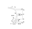
- FIG. 2 is a meridian cross-sectional view schematically showing the pneumatic tire of FIG.
- FIG. 3 is a cross-sectional view taken along the equator line schematically showing the pneumatic tire of FIG.
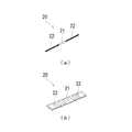
- FIG. 4 is an enlarged cross-sectional view of the transponder embedded in the pneumatic tire of FIG. 5 (a) and 5 (b) are perspective views showing a transponder that can be embedded in a pneumatic tire according to the present invention.
- FIG. 6 is a meridian cross-sectional view schematically showing a modified example of the pneumatic tire according to the embodiment of the present invention.
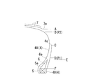
- FIG. 7 is an explanatory view showing the position in the tire radial direction of the terminal of the winding portion of the carcass layer in the test tire.
- FIGS. 1 to 4 show pneumatic tires according to the embodiment of the present invention.
- the pneumatic tire of the present embodiment includes a tread portion 1 extending in the tire circumferential direction to form an annular shape, a pair of sidewall portions 2 arranged on both sides of the tread portion 1, and these. It includes a pair of bead portions 3 arranged inside the sidewall portion 2 in the tire radial direction.
- At least one layer (one layer in FIG. 1) of the carcass layer 4 formed by arranging a plurality of carcass cords in the radial direction is mounted.
- the carcass cord constituting the carcass layer 4 an organic fiber cord such as nylon or polyester is preferably used.
- An annular bead core 5 is embedded in each bead portion 3, and a bead filler 6 made of a rubber composition having a triangular cross section is arranged on the outer periphery of the bead core 5.
- a plurality of layers (two layers in FIG. 1) of belt layers 7 are embedded on the outer peripheral side of the tire of the carcass layer 4 in the tread portion 1.
- the belt layer 7 includes a plurality of reinforcing cords that are inclined with respect to the tire circumferential direction, and the reinforcing cords are arranged so as to intersect each other between the layers.
- the inclination angle of the reinforcing cord with respect to the tire circumferential direction is set in the range of, for example, 10 ° to 40 °.
- a steel cord is preferably used as the reinforcing cord of the belt layer 7.
- the belt cover layer 8 On the outer peripheral side of the tire of the belt layer 7, at least one layer (two layers in FIG. 1) in which reinforcing cords are arranged at an angle of, for example, 5 ° or less with respect to the tire peripheral direction for the purpose of improving high-speed durability.
- the belt cover layer 8 is arranged.
- the belt cover layer 8 located inside the tire radial direction constitutes a full cover covering the entire width of the belt layer 7, and the belt cover layer 8 located outside the tire radial direction covers only the end portion of the belt layer 7. It constitutes an edge cover layer.
- an organic fiber cord such as nylon or aramid is preferably used as the reinforcing cord of the belt cover layer 8.
- both terminals 4e of the carcass layer 4 are arranged so as to be folded back from the inside to the outside of each bead core 5 and to wrap the bead core 5 and the bead filler 6.
- the carcass layer 4 is wound around the bead core 5 in each bead portion 3 and the main body portion 4A which is a portion extending from the tread portion 1 through each sidewall portion 2 to each bead portion 3, and is wound up on each sidewall portion 2 side. It includes a winding portion 4B which is a portion extending toward the direction.
- the cap tread rubber layer 11 is arranged on the tread portion 1
- the sidewall rubber layer 12 is arranged on the sidewall portion 2
- the rim cushion rubber layer 13 is arranged on the bead portion 3.
- the rubber layer 10 arranged on the outside of the carcass layer 4 in the sidewall portion 2 includes the sidewall rubber layer 12 and the rim cushion rubber layer 13.
- a transponder 20 is embedded between the carcass layer 4 and the rubber layer 10 so as to abut the rubber layer 10. That is, the transponder 20 is arranged between the carcass layer 4 and the sidewall rubber layer 12 or the rim cushion rubber layer 13 while being in contact with the rubber layer as an arrangement area in the tire width direction. Further, the transponder 20 is arranged as an arrangement area in the tire radial direction at a distance of 10 mm or more in the tire radial direction from the terminal 4e of the winding portion 4B of the carcass layer 4. Further, the transponder 20 extends along the tire circumferential direction. The transponder 20 may be arranged so as to be inclined in the range of ⁇ 10 ° to 10 ° with respect to the tire circumferential direction.
- the transponder 20 is arranged at a distance of 10 mm or more from the terminal 4e of the winding portion 4B of the carcass layer 4 in the tire radial direction, but the present invention is limited to this. Instead, the transponder 20 may be arranged at a distance of 10 mm or more from the terminal 4e of the winding portion 4B of the carcass layer 4 on the outer side in the tire radial direction. That is, in the present invention, the transponder 20 may be arranged at a distance of 10 mm or more in the tire radial direction from the terminal 4e of the winding portion 4B of the carcass layer 4. Further, in the embodiments of FIGS.
- the terminal 4e of the winding portion 4B of the carcass layer 4 is arranged in the middle of the sidewall portion 2, but the terminal 4e of the winding portion 4B of the carcass layer 4 is shown. It may be arranged on the side of the bead core 5.
- the transponder 20 is arranged between the carcass layer 4 (more specifically, the bead filler 6) and the sidewall rubber layer 12 or the rim cushion rubber layer 13 while abutting against the rubber layer. You may have.
- the transponder 20 for example, an RFID (Radio Frequency Identification) tag can be used.
- the transponder 20 has an IC substrate 21 for storing data and an antenna 22 for transmitting and receiving data in a non-contact manner.
- RFID is an automatic recognition technology that is composed of a reader / writer having an antenna and a controller, an IC board, and an ID tag having an antenna, and can communicate data wirelessly.
- the overall shape of the transponder 20 is not particularly limited, and for example, a columnar or plate-shaped transponder can be used as shown in FIGS. 5 (a) and 5 (b).
- a columnar or plate-shaped transponder can be used as shown in FIGS. 5 (a) and 5 (b).
- the transponder 20 shown in FIG. 5A it is preferable because it can follow the deformation of the tire in each direction.
- the transponder 20's antenna 22 protrudes from each of both ends of the IC substrate 21 and has a spiral shape. As a result, it is possible to follow the deformation of the tire during traveling, and it is possible to improve the durability of the transponder 20. Further, communication can be ensured by appropriately changing the length of the antenna 22.
- the transponder 20 extends along the tire circumferential direction while contacting the rubber layer 10 between the carcass layer 4 and the rubber layer 10 arranged on the outside of the carcass layer 4 at the sidewall portion 2. Is buried, and the transponder 20 is arranged at a distance of 10 mm or more in the tire radial direction from the terminal 4e of the winding portion 4B of the carcass layer 4, so that the arrangement of the transponder 20 does not disturb the carcass line and stabilizes the steering of the tire. The sex can be improved. In addition, metal interference is unlikely to occur, and the communicability of the transponder 20 can be ensured.
- the durability of the tire can be improved.
- the terminal 4e of the winding portion 4B of the carcass layer 4 located on the outermost side in the tire width direction in the sidewall portion 2 has a position P1 5 mm outward in the tire radial direction from the upper end 6e of the bead filler 6 and a belt.
- the transponder 20 is arranged between the terminal 7e of the layer 7 and the position P2 15 mm inward in the tire radial direction, and the transponder 20 is arranged 15 mm or more inward from the upper end 5e of the bead core 5 in the tire radial direction. That is, the terminal 4e of the winding portion 4B of the carcass layer 4 is arranged in the region S1 shown in FIG.
- the transponder 20 is arranged in a region outside the tire radial direction from the position P3 shown in FIG. 2 and excluding the region S2. Is good.
- the position P2 is set as the upper limit of the tire radial position on the terminal 4e of the winding portion 4B of the carcass layer 4
- the upper limit of the tire radial position of the transponder 20 is correspondingly in the tire radial direction from the position P2. It is preferable that the position is 10 mm on the outside (in other words, the position is 5 mm on the inside in the tire radial direction from the terminal 7e of the belt layer 7).
- the durability of the tire is effectively improved. Can be done.
- the transponder 20 is arranged outside the position P3 in the tire radial direction, metal interference is unlikely to occur, and the communication property of the transponder can be sufficiently ensured.
- the transponder 20 is arranged inside the tire radial direction from the position P3, metal interference with the rim flange occurs, and the communication property of the transponder 20 tends to deteriorate.
- FIG. 3 shows the position Q of each splice portion in the tire circumferential direction.
- the center of the transponder 20 is preferably arranged at a distance of 10 mm or more in the tire circumferential direction from the splice portion of the tire component member. That is, it is preferable that the transponder 20 is arranged in the region S3 shown in FIG. Specifically, it is preferable that the IC substrate 21 constituting the transponder 20 is separated from the position Q by 10 mm or more in the tire circumferential direction.
- the entire transponder 20 including the antenna 22 is separated from the position Q in the tire circumferential direction by 10 mm or more, and the entire transponder 20 in the state of being covered with the covering rubber is in the tire circumferential direction from the position Q. Most preferably, they are separated by 10 mm or more.
- the sidewall rubber layer 12 or the rim cushion rubber layer 13 or the carcass layer 4 are arranged adjacent to the transponder 20.
- the positions Q of the splice portions of each tire component member in the tire circumferential direction are arranged at equal intervals, but the present invention is not limited to this.
- the position Q in the tire circumferential direction can be set to an arbitrary position, and in any case, the transponder 20 is arranged so as to be separated from the splice portion of each tire component by 10 mm or more in the tire circumferential direction.
- the distance d between the cross-sectional center of the transponder 20 and the outer surface of the tire is preferably 2 mm or more.
- the transponder 20 is covered with the coating layer 23.
- the coating layer 23 covers the entire transponder 20 so as to sandwich both the front and back surfaces of the transponder 20.
- the coating layer 23 may be made of rubber having the same physical characteristics as the rubber constituting the sidewall rubber layer 12 or the rim cushion rubber layer 13, or may be made of rubber having different physical characteristics. Since the transponder 20 is protected by the coating layer 23 in this way, the durability of the transponder 20 can be improved.
- the relative permittivity of the coating layer 23 is preferably 7 or less, and more preferably 2 to 5 in a state where the transponder 20 is covered with the coating layer 23.
- the relative permittivity of the rubber constituting the coating layer 23 is a relative permittivity of 860 MHz to 960 MHz at room temperature.
- the room temperature conforms to the standard state of the JIS standard, and is 23 ⁇ 2 ° C. and 60% ⁇ 5% RH.
- the relative permittivity of the rubber is measured after being treated at 23 ° C.
- the above-mentioned range of 860 MHz to 960 MHz corresponds to the current assigned frequency of RFID in the UHF band, but when the above-mentioned allotted frequency is changed, the relative permittivity of the allotted frequency range may be defined as described above.
- the thickness t of the coating layer 23 is preferably 0.5 mm to 3.0 mm, more preferably 1.0 mm to 2.5 mm.
- the thickness t of the coating layer 23 is the rubber thickness at the position including the transponder 20, and is, for example, on a straight line passing through the center of the transponder 20 and orthogonal to the outer surface of the tire as shown in FIG. It is the total rubber thickness of the thickness t1 and the thickness t2.
- the cross-sectional shape of the covering layer 23 is not particularly limited, but for example, a triangular shape, a rectangular shape, a trapezoidal shape, or a spindle shape can be adopted.
- the coating layer 23 of FIG. 4 has a substantially spindle-shaped cross-sectional shape.
- FIG. 6 shows a modified example of the pneumatic tire according to the embodiment of the present invention.
- the same objects as those in FIGS. 1 to 4 are designated by the same reference numerals, and detailed description of the parts thereof will be omitted.
- the present embodiment has two carcass layers 4.
- the carcass layer 4 includes an inner peripheral side carcass layer 41 located inside the tire radial direction in the tread portion 1 and an outer peripheral side carcass layer 42 located outside the tire radial direction in the tread portion 1.
- the transponder 20 is arranged at a distance of 10 mm or more in the tire radial direction from each of the terminal 41e of the winding portion 41B of the inner peripheral side carcass layer 41 and the terminal 42e of the winding portion 42B of the outer peripheral side carcass layer 42.
- the terminal 41e of the winding portion 41B of the inner peripheral side carcass layer 41 located on the outermost side in the tire width direction in the sidewall portion 2 is arranged in the region S1, and the transponder 20 is outside the position P3 in the tire radial direction and is located in the region S2. And it is preferable that it is arranged in an area other than the area S4.
- a tread portion extending in the tire circumferential direction to form an annular shape, a pair of sidewall portions arranged on both sides of the tread portion, and these sidewall portions are arranged inside the tire radial direction.
- a pair of bead portions are provided, a bead filler is arranged on the outer periphery of the bead core of each bead portion, a carcass layer is mounted between the pair of bead portions, and a plurality of belt layers are mounted on the outer peripheral side of the carcass layer in the tread portion.
- the position of the transponder (tire circumferential direction) indicates the distance [mm] measured in the tire circumferential direction from the center of the transponder to the splice portion of the tire component.
- the terminal positions of the winding portions correspond to the respective positions A to E shown in FIG. 7. In FIG. 7, an example in which the terminal position of the winding portion is “C” is used.
- tire evaluation (steering stability, durability, trauma resistance and appearance) and transponder evaluation (communication and durability) were carried out by the following test methods, and the results are shown in Tables 1 and 2. Also shown.
- Durability (tires and transponders): After assembling each test tire to the wheel of the standard rim and conducting a running test with a drum tester under the conditions of an air pressure of 120 kPa, 102% of the maximum load, and a running speed of 81 km, running when a tire failure occurs. The distance was measured. The evaluation results are indicated by “ ⁇ (excellent)” when the mileage reaches 6480 km, “ ⁇ (good)” when the mileage is 4050 km or more and less than 6480 km, and when the mileage is 3240 km or more and less than 4050 km. Is indicated by “ ⁇ (possible)", and the case where the mileage is less than 3240 km is indicated by four stages of "x (impossible)". Further, after the running was completed, the outer surface of each test tire was visually inspected to confirm whether or not the tire failure originated from the transponder. The evaluation result showed the presence or absence of the failure.
- transponder For each test tire, communication work with the transponder was carried out using a reader / writer. Specifically, the maximum distance that can be communicated with a reader / writer with an output of 250 mW and a carrier frequency of 860 MHz to 960 MHz was measured. The evaluation results are indicated by " ⁇ (excellent)” when the communication distance is 500 mm or more, “ ⁇ (good)” when the communication distance is 150 mm or more and less than 500 mm, and " ⁇ ( ⁇ ) when the communication distance is less than 150 mm. Yes) ”was shown in three stages.
- the pneumatic tires of Examples 1 to 18 had improved tire steering stability, tire durability, and transponder communication in a well-balanced manner.
- the pneumatic tire of Example 9 since the distance between the transponder and the outer surface of the tire was set short, the trauma resistance of the tire was lowered.
- the thickness of the coating layer covering the transponder was set to be thick, so that the appearance of the tire was deteriorated. Since the pneumatic tire of Example 18 used a columnar transponder, the durability of the transponder was improved, and there was no failure starting from the transponder.
- Comparative Example 1 since the transponder was arranged between the bead filler and the carcass layer, the steering stability of the tire deteriorated. In Comparative Examples 1 to 3, since the transponder was arranged at the same height as the terminal position of the winding portion of the carcass layer, the durability of the tire deteriorated. In Comparative Example 4, since the distance between the transponder and the terminal position of the winding portion of the carcass layer was not sufficiently secured, the durability of the tire deteriorated. In Comparative Example 5, the distance between the transponder and the terminal position of the winding portion of the carcass layer was secured, but since the transponder was arranged between the bead filler and the carcass layer, the steering stability of the tire deteriorated. did.
Landscapes
- Engineering & Computer Science (AREA)
- Mechanical Engineering (AREA)
- Tires In General (AREA)
Abstract
トランスポンダの通信性を確保しながら、タイヤの操縦安定性及び耐久性を改善することを可能にした空気入りタイヤを提供する。カーカス層4が各ビード部のビードコア5の廻りにタイヤ内側から外側へ巻き上げられた構造を有する空気入りタイヤにおいて、カーカス層4とサイドウォール部でカーカス層4の外側に配置されたゴム層との間に該ゴム層に当接しながらタイヤ周方向に沿って延在するトランスポンダ20が埋設され、トランスポンダ20はカーカス層4の巻き上げ部4Bの端末4eからタイヤ径方向に10mm以上離間して配置されている。
Description
本発明は、トランスポンダが埋設された空気入りタイヤに関し、更に詳しくは、トランスポンダの通信性を確保しながら、タイヤの操縦安定性及び耐久性を改善することを可能にした空気入りタイヤに関する。
空気入りタイヤにおいて、RFIDタグ(トランスポンダ)をタイヤ内に埋設することが提案されている(例えば、特許文献1参照)。トランスポンダをタイヤ内に埋設する場合、例えば、トランスポンダをカーカス層とビードフィラーとの間に配置すると、カーカス層におけるカーカスラインが乱れ、タイヤの操縦安定性が悪化するという問題がある。また、カーカス層の巻き上げ部の端末位置によっては、トランスポンダとカーカス層の巻き上げ部の端末との距離が極端に小さくなり、トランスポンダを起点としてタイヤが損傷することがある。更に、トランスポンダを金属製のタイヤ構成部材(例えば、ビードコア等)の近くに配置すると、そのタイヤ構成部材とトランスポンダとが干渉して、トランスポンダの通信性が悪化するという問題がある。
本発明の目的は、トランスポンダの通信性を確保しながら、タイヤの操縦安定性及び耐久性を改善することを可能にした空気入りタイヤを提供することにある。
上記目的を達成するため本発明の空気入りタイヤは、タイヤ周方向に延在して環状をなすトレッド部と、該トレッド部の両側に配置された一対のサイドウォール部と、これらサイドウォール部のタイヤ径方向内側に配置された一対のビード部とを備え、各ビード部のビードコアの外周上にビードフィラーが配置され、前記一対のビード部間に少なくとも1層のカーカス層が装架され、前記トレッド部における前記カーカス層の外周側に複数層のベルト層が配置され、前記カーカス層が前記ビードコアの廻りにタイヤ内側から外側へ巻き上げられた構造を有する空気入りタイヤにおいて、前記カーカス層と前記サイドウォール部で前記カーカス層の外側に配置されたゴム層との間に該ゴム層に当接しながらタイヤ周方向に沿って延在するトランスポンダが埋設され、該トランスポンダが前記カーカス層の巻き上げ部の端末からタイヤ径方向に10mm以上離間して配置されていることを特徴とするものである。
本発明では、カーカス層が各ビード部のビードコアの廻りにタイヤ内側から外側へ巻き上げられた構造を有する空気入りタイヤにおいて、カーカス層とサイドウォール部でカーカス層の外側に配置されたゴム層との間にゴム層に当接しながらタイヤ周方向に沿って延在するトランスポンダが埋設され、トランスポンダはカーカス層の巻き上げ部の端末からタイヤ径方向に10mm以上離間して配置されているので、トランスポンダの配置によってカーカスラインを乱すことがなく、タイヤの操縦安定性を改善することができる。また、金属干渉が生じにくく、トランスポンダの通信性を確保することができる。トランスポンダとカーカス層の巻き上げ部の端末との距離が極端に小さいと、応力集中が発生してタイヤの耐久性が悪化することがあるが、上述したように当該距離を確保することで、タイヤの耐久性を改善することができる。
本発明の空気入りタイヤにおいて、サイドウォール部においてタイヤ幅方向最外側に位置するカーカス層の巻き上げ部の端末はビードフィラーの上端からタイヤ径方向外側に5mmの位置とベルト層の端末からタイヤ径方向内側に15mmの位置との間に配置され、トランスポンダはビードコアの上端からタイヤ径方向外側に15mm以上離間して配置されていることが好ましい。サイドウォール部においてタイヤ幅方向最外側に位置するカーカス層の巻き上げ部の端末が上述した領域にあることで、タイヤの耐久性を効果的に改善することができる。また、トランスポンダがビードコアの上端からタイヤ径方向外側に15mm以上離間して配置されていることで、金属干渉が生じにくく、トランスポンダの通信性を十分に確保することができる。
トランスポンダの中心はタイヤ構成部材のスプライス部からタイヤ周方向に10mm以上離間して配置されていることが好ましい。これにより、タイヤの耐久性を効果的に改善することができる。
トランスポンダの断面中心とタイヤ外表面との距離は2mm以上であることが好ましい。これにより、タイヤの耐久性を効果的に改善することができると共に、タイヤの耐外傷性を改善することができる。
トランスポンダは被覆層により被覆され、被覆層の比誘電率は7以下であることが好ましい。これにより、トランスポンダが被覆層により保護され、トランスポンダの耐久性を改善することができると共に、トランスポンダの電波透過性を確保し、トランスポンダの通信性を効果的に改善することができる。
トランスポンダは被覆層により被覆され、被覆層の厚さは0.5mm~3.0mmであることが好ましい。これにより、タイヤ外表面に凹凸を生じさせることなく、トランスポンダの通信性を効果的に改善することができる。
トランスポンダはデータを記憶するIC基板とデータを送受信するアンテナとを有し、アンテナは螺旋状であることが好ましい。これにより、走行時におけるタイヤの変形に対して追従することができ、トランスポンダの耐久性を改善することができる。
以下、本発明の構成について添付の図面を参照しながら詳細に説明する。図1~4は本発明の実施形態からなる空気入りタイヤを示すものである。
図1に示すように、本実施形態の空気入りタイヤは、タイヤ周方向に延在して環状をなすトレッド部1と、トレッド部1の両側に配置された一対のサイドウォール部2と、これらサイドウォール部2のタイヤ径方向内側に配置された一対のビード部3とを備えている。
一対のビード部3間には、複数本のカーカスコードをラジアル方向に配列してなる少なくとも1層(図1では1層)のカーカス層4が装架されている。カーカス層4を構成するカーカスコードとしては、ナイロンやポリエステル等の有機繊維コードが好ましく使用される。各ビード部3には環状のビードコア5が埋設されており、そのビードコア5の外周上に断面三角形状のゴム組成物からなるビードフィラー6が配置されている。
一方、トレッド部1におけるカーカス層4のタイヤ外周側には、複数層(図1では2層)のベルト層7が埋設されている。ベルト層7は、タイヤ周方向に対して傾斜する複数本の補強コードを含み、かつ層間で補強コードが互いに交差するように配置されている。ベルト層7において、補強コードのタイヤ周方向に対する傾斜角度は例えば10°~40°の範囲に設定されている。ベルト層7の補強コードとしては、スチールコードが好ましく使用される。
ベルト層7のタイヤ外周側には、高速耐久性の向上を目的として、補強コードをタイヤ周方向に対して例えば5°以下の角度で配列してなる少なくとも1層(図1では2層)のベルトカバー層8が配置されている。図1において、タイヤ径方向内側に位置するベルトカバー層8はベルト層7の全幅を覆うフルカバーを構成し、タイヤ径方向外側に位置するベルトカバー層8はベルト層7の端部のみを覆うエッジカバー層を構成している。ベルトカバー層8の補強コードとしては、ナイロンやアラミド等の有機繊維コードが好ましく使用される。
上記空気入りタイヤにおいて、カーカス層4の両端末4eは、各ビードコア5の廻りにタイヤ内側から外側へ折り返され、ビードコア5及びビードフィラー6を包み込むように配置されている。カーカス層4は、トレッド部1から各サイドウォール部2を経て各ビード部3に至る部分である本体部4Aと、各ビード部3においてビードコア5の廻りに巻き上げられて各サイドウォール部2側に向かって延在する部分である巻き上げ部4Bとを含む。
また、トレッド部1にはキャップトレッドゴム層11が配置され、サイドウォール部2にはサイドウォールゴム層12が配置され、ビード部3にはリムクッションゴム層13が配置されている。サイドウォール部2でカーカス層4の外側に配置されたゴム層10は、サイドウォールゴム層12とリムクッションゴム層13とを含む。
また、上記空気入りタイヤにおいて、カーカス層4とゴム層10との間には、ゴム層10に当接するようにトランスポンダ20が埋設されている。即ち、トランスポンダ20は、タイヤ幅方向の配置領域として、カーカス層4とサイドウォールゴム層12又はリムクッションゴム層13との間に当該ゴム層に当接しながら配置されている。また、トランスポンダ20は、タイヤ径方向の配置領域として、カーカス層4の巻き上げ部4Bの端末4eからタイヤ径方向に10mm以上離間して配置されている。また、トランスポンダ20はタイヤ周方向に沿って延在している。トランスポンダ20は、タイヤ周方向に対して-10°~10°の範囲で傾斜するように配置しても良い。
なお、図1及び図2の実施形態では、トランスポンダ20がカーカス層4の巻き上げ部4Bの端末4eからタイヤ径方向内側に10mm以上離間して配置された例を示したが、これに限定されるものではなく、トランスポンダ20がカーカス層4の巻き上げ部4Bの端末4eからタイヤ径方向外側に10mm以上離間して配置されていても良い。即ち、本発明では、トランスポンダ20がカーカス層4の巻き上げ部4Bの端末4eからタイヤ径方向に10mm以上離間して配置されていれば良い。また、図1及び図2の実施形態では、カーカス層4の巻き上げ部4Bの端末4eがサイドウォール部2の中腹に配置された例を示したが、カーカス層4の巻き上げ部4Bの端末4eがビードコア5の側方に配置されていても良い。このようなロータンナップ構造において、トランスポンダ20は、カーカス層4(より具体的にはビードフィラー6)とサイドウォールゴム層12又はリムクッションゴム層13との間に当該ゴム層に当接しながら配置されていても良い。
トランスポンダ20として、例えば、RFID(Radio Frequency Identification)タグを用いることができる。トランスポンダ20は、図5(a),(b)に示すにように、データを記憶するIC基板21とデータを非接触で送受信するアンテナ22とを有している。このようなトランスポンダ20を用いることで、適時にタイヤに関する情報を書き込み又は読み出し、タイヤを効率的に管理することができる。なお、RFIDとは、アンテナ及びコントローラを有するリーダライタと、IC基板及びアンテナを有するIDタグから構成され、無線方式によりデータを交信可能な自動認識技術である。
トランスポンダ20の全体の形状は、特に限定されるものではなく、例えば、図5(a),(b)に示すにように柱状や板状のものを用いることができる。特に、図5(a)に示す柱状のトランスポンダ20を用いた場合、タイヤの各方向の変形に対して追従することができるので好適である。この場合、トランスポンダ20のアンテナ22は、IC基板21の両端部の各々から突出し、螺旋状を呈している。これにより、走行時におけるタイヤの変形に対して追従することができ、トランスポンダ20の耐久性を改善することができる。更に、アンテナ22の長さを適宜変更することにより、通信性を確保することができる。
上述した空気入りタイヤでは、カーカス層4とサイドウォール部2でカーカス層4の外側に配置されたゴム層10との間にゴム層10に当接しながらタイヤ周方向に沿って延在するトランスポンダ20が埋設され、トランスポンダ20はカーカス層4の巻き上げ部4Bの端末4eからタイヤ径方向に10mm以上離間して配置されているので、トランスポンダ20の配置によってカーカスラインを乱すことがなく、タイヤの操縦安定性を改善することができる。また、金属干渉が生じにくく、トランスポンダ20の通信性を確保することができる。トランスポンダ20とカーカス層4の巻き上げ部4Bの端末4eとの距離が極端に小さいと、応力集中が発生してタイヤの耐久性が悪化することがあるが、上述したように当該距離を確保することで、タイヤの耐久性を改善することができる。
上記空気入りタイヤにおいて、サイドウォール部2においてタイヤ幅方向最外側に位置するカーカス層4の巻き上げ部4Bの端末4eは、ビードフィラー6の上端6eからタイヤ径方向外側に5mmの位置P1と、ベルト層7の端末7eからタイヤ径方向内側に15mmの位置P2との間に配置され、トランスポンダ20はビードコア5の上端5eからタイヤ径方向外側に15mm以上離間して配置されていると良い。即ち、カーカス層4の巻き上げ部4Bの端末4eは図2に示す領域S1に配置され、トランスポンダ20は図2に示す位置P3よりタイヤ径方向外側であって領域S2を除く領域に配置されていると良い。但し、カーカス層4の巻き上げ部4Bの端末4eは、タイヤ径方向位置の上限として位置P2が設定されているので、トランスポンダ20のタイヤ径方向位置の上限は、それに応じて位置P2よりタイヤ径方向外側に10mmの位置(言い換えれば、ベルト層7の端末7eからタイヤ径方向内側に5mmの位置)とすることが良い。
上述した空気入りタイヤでは、サイドウォール部2においてタイヤ幅方向最外側に位置するカーカス層4の巻き上げ部4Bの端末4eが領域S1に配置された場合、タイヤの耐久性を効果的に改善することができる。また、トランスポンダ20が位置P3よりタイヤ径方向外側に配置された場合、金属干渉が生じにくく、トランスポンダの通信性を十分に確保することができる。ここで、トランスポンダ20が位置P3よりタイヤ径方向内側に配置されていると、リムフランジとの金属干渉が発生し、トランスポンダ20の通信性が低下する傾向がある。一方、カーカス層4の巻き上げ部4Bの端末4eが、位置P1よりタイヤ径方向内側或いは位置P2よりタイヤ径方向外側に配置されると、タイヤの耐久性が悪化する傾向がある。
図3に示すように、タイヤ周上には、タイヤ構成部材の端部同士が重ねられてなる複数のスプライス部がある。図3には各スプライス部のタイヤ周方向の位置Qが示されている。トランスポンダ20の中心は、タイヤ構成部材のスプライス部からタイヤ周方向に10mm以上離間して配置されていることが好ましい。即ち、トランスポンダ20は、図3に示す領域S3に配置されていると良い。具体的には、トランスポンダ20を構成するIC基板21が位置Qからタイヤ周方向に10mm以上離間していると良い。更には、アンテナ22を含むトランスポンダ20の全体が位置Qからタイヤ周方向に10mm以上離間していることがより好ましく、被覆ゴムにより被覆された状態のトランスポンダ20の全体が位置Qからタイヤ周方向に10mm以上離間していることが最も好ましい。また、トランスポンダ20と離間して配置するタイヤ構成部材として、トランスポンダ20と隣接して配置されるサイドウォールゴム層12又はリムクッションゴム層13、或いはカーカス層4であることが好ましい。このようにタイヤ構成部材のスプライス部から離間させてトランスポンダ20を配置することで、タイヤの耐久性を効果的に改善することができる。
なお、図3の実施形態では、各タイヤ構成部材のスプライス部のタイヤ周方向の位置Qが等間隔に配置された例を示したが、これに限定されるものではない。タイヤ周方向の位置Qは任意の位置に設定することができ、いずれの場合であってもトランスポンダ20は各タイヤ構成部材のスプライス部からタイヤ周方向に10mm以上離間するように配置される。
図4に示すように、トランスポンダ20の断面中心とタイヤ外表面との距離dは2mm以上であることが好ましい。このようにトランスポンダ20とタイヤ外表面とを離間させることで、タイヤの耐久性を効果的に改善することができると共に、タイヤの耐外傷性を改善することができる。
また、トランスポンダ20は被覆層23により被覆されていると良い。この被覆層23は、トランスポンダ20の表裏両面を挟むようにしてトランスポンダ20の全体を被覆する。被覆層23は、サイドウォールゴム層12又はリムクッションゴム層13を構成するゴムと同じ物性を有するゴムで構成しても良く、異なる物性を有するゴムで構成しても良い。このようにトランスポンダ20が被覆層23により保護されていることで、トランスポンダ20の耐久性を改善することができる。
上記空気入りタイヤにおいて、トランスポンダ20が被覆層23により被覆された状態で、被覆層23の比誘電率は7以下であることが好ましく、2~5であることがより好ましい。このように被覆層23の比誘電率を適度に設定することで、トランスポンダ20が電波を放射する際の電波透過性を確保し、トランスポンダ20の通信性を効果的に改善することができる。なお、被覆層23を構成するゴムの比誘電率は、常温において860MHz~960MHzの比誘電率である。ここで、常温はJIS規格の標準状態に準拠し、23±2℃、60%±5%RHである。当該ゴムは23℃、60%RHで24時間処理された後に比誘電率が計測される。上述した860MHz~960MHzの範囲は、現状のUHF帯のRFIDの割り当て周波数に該当するが、上記割り当て周波数が変更された場合、その割り当て周波数の範囲の比誘電率を上記の如く規定すれば良い。
また、トランスポンダ20が被覆層23により被覆された状態で、被覆層23の厚さtは0.5mm~3.0mmであることが好ましく、1.0mm~2.5mmであることがより好ましい。ここで、被覆層23の厚さtは、トランスポンダ20を含む位置でのゴム厚さであり、例えば、図4に示すようにトランスポンダ20の中心を通ってタイヤ外表面と直交する直線上での厚さt1と厚さt2を合計したゴム厚さである。このように被覆層23の厚さtを適度に設定することで、タイヤ外表面に凹凸を生じさせることなく、トランスポンダ20の通信性を効果的に改善することができる。ここで、被覆層23の厚さtが0.5mmより薄いと、トランスポンダ20の通信性の改善効果を得ることができず、逆に被覆層23の厚さtが3.0mmを超えると、タイヤ外表面に凹凸が生じ、外観上好ましくない。なお、被覆層23の断面形状は、特に限定されるものではないが、例えば、三角形や長方形、台形、紡錘形を採用することができる。図4の被覆層23では略紡錘形の断面形状を有している。
図6は本発明の実施形態からなる空気入りタイヤの変形例を示すものである。図6において、図1~図4と同一物には同一符号を付してその部分の詳細な説明は省略する。
図6に示すように、本実施形態では2層のカーカス層4を有している。カーカス層4は、トレッド部1においてタイヤ径方向内側に位置する内周側カーカス層41と、トレッド部1においてタイヤ径方向外側に位置する外周側カーカス層42とを含んでいる。この場合、トランスポンダ20は、内周側カーカス層41の巻き上げ部41Bの端末41e及び外周側カーカス層42の巻き上げ部42Bの端末42eのそれぞれからタイヤ径方向に10mm以上離間して配置されている。また、サイドウォール部2においてタイヤ幅方向最外側に位置する内周側カーカス層41の巻き上げ部41Bの端末41eは領域S1に配置され、トランスポンダ20は位置P3よりタイヤ径方向外側であって領域S2及び領域S4を除く領域に配置されていると良い。
タイヤサイズ265/40ZR20で、タイヤ周方向に延在して環状をなすトレッド部と、トレッド部の両側に配置された一対のサイドウォール部と、これらサイドウォール部のタイヤ径方向内側に配置された一対のビード部とを備え、各ビード部のビードコアの外周上にビードフィラーが配置され、一対のビード部間にカーカス層が装架され、トレッド部におけるカーカス層の外周側に複数層のベルト層が配置され、カーカス層がビードコアの廻りにタイヤ内側から外側へ巻き上げられた構造を有する空気入りタイヤにおいて、タイヤ周方向に沿って延在するトランスポンダが埋設され、トランスポンダの位置(タイヤ幅方向、タイヤ径方向及びタイヤ周方向)、巻き上げ部の端末位置、トランスポンダとタイヤ外表面の距離、被覆層の比誘電率、被覆層の厚さ、トランスポンダの形態を表1及び表2のように設定した比較例1~5及び実施例1~18のタイヤを製作した。
なお、表1及び表2において、トランスポンダの位置(タイヤ幅方向)が「X」の場合、トランスポンダがビードフィラーとカーカス層との間に配置され、トランスポンダの位置(タイヤ幅方向)が「Y」の場合、トランスポンダがカーカス層とサイドウォールゴム層との間にサイドウォールゴム層に当接して配置され、トランスポンダの位置(タイヤ幅方向)が「Z」の場合、トランスポンダがカーカス層とリムクッションゴム層との間にリムクッションゴム層に当接して配置されていることを示す。トランスポンダの位置(タイヤ径方向)は、カーカス層の巻き上げ部の端末からタイヤ径方向に測定された距離[mm]を示す。トランスポンダの位置(タイヤ周方向)は、トランスポンダの中心からタイヤ構成部材のスプライス部までのタイヤ周方向に測定された距離[mm]を示す。また、表1及び表2において、巻き上げ部の端末位置は、図7に示すA~Eのそれぞれの位置に対応する。図7では巻き上げ部の端末位置が「C」の例を使用している。
これら試験タイヤについて、下記試験方法により、タイヤ評価(操縦安定性、耐久性、耐外傷性及び外観性)並びにトランスポンダ評価(通信性及び耐久性)を実施し、その結果を表1及び表2に併せて示した。
操縦安定性(タイヤ):
各試験タイヤを標準リムのホイールに組み付けて試験車両に装着し、テストドライバーによるテストコースでの官能評価を実施した。評価結果は、非常に良好である場合を「◎(優)」で示し、良好である場合を「○(良)」で示し、若干劣る場合を「△(可)」とする3段階で示した。
各試験タイヤを標準リムのホイールに組み付けて試験車両に装着し、テストドライバーによるテストコースでの官能評価を実施した。評価結果は、非常に良好である場合を「◎(優)」で示し、良好である場合を「○(良)」で示し、若干劣る場合を「△(可)」とする3段階で示した。
耐久性(タイヤ及びトランスポンダ):
各試験タイヤを標準リムのホイールに組み付け、空気圧120kPa、最大負荷荷重に対して102%、走行速度81kmの条件でドラム試験機にて走行試験を実施した後、タイヤに故障が発生した際の走行距離を測定した。評価結果は、走行距離が6480kmに達した場合を「◎(優)」で示し、走行距離が4050km以上6480km未満の場合を「○(良)」で示し、走行距離が3240km以上4050km未満の場合を「△(可)」で示し、走行距離が3240km未満の場合を「×(不可)」の4段階で示した。更に、走行終了後に各試験タイヤのタイヤ外表面を目視し、タイヤの故障がトランスポンダを起点とするものであるか否かを確認した。評価結果はその故障の有無を示した。
各試験タイヤを標準リムのホイールに組み付け、空気圧120kPa、最大負荷荷重に対して102%、走行速度81kmの条件でドラム試験機にて走行試験を実施した後、タイヤに故障が発生した際の走行距離を測定した。評価結果は、走行距離が6480kmに達した場合を「◎(優)」で示し、走行距離が4050km以上6480km未満の場合を「○(良)」で示し、走行距離が3240km以上4050km未満の場合を「△(可)」で示し、走行距離が3240km未満の場合を「×(不可)」の4段階で示した。更に、走行終了後に各試験タイヤのタイヤ外表面を目視し、タイヤの故障がトランスポンダを起点とするものであるか否かを確認した。評価結果はその故障の有無を示した。
耐外傷性(タイヤ):
各試験タイヤを標準リムのホイールに組み付けて試験車両に装着し、空気圧230kPa、走行速度20km/hの条件で、高さ100mmの縁石に接触させながら走行するという走行試験を実施した。走行後に目視でタイヤ外表面の破損の有無を確認した。評価結果は、タイヤ外表面の破損の有無を示した。
各試験タイヤを標準リムのホイールに組み付けて試験車両に装着し、空気圧230kPa、走行速度20km/hの条件で、高さ100mmの縁石に接触させながら走行するという走行試験を実施した。走行後に目視でタイヤ外表面の破損の有無を確認した。評価結果は、タイヤ外表面の破損の有無を示した。
外観性(タイヤ):
各試験タイヤについて、トランスポンダの配置箇所に対応するタイヤ外表面を目視で確認した。評価結果は、タイヤ外表面においてトランスポンダの配置に起因する凹凸がなかった場合を「良好」とし、凹凸があった場合を「不良」として示した。
各試験タイヤについて、トランスポンダの配置箇所に対応するタイヤ外表面を目視で確認した。評価結果は、タイヤ外表面においてトランスポンダの配置に起因する凹凸がなかった場合を「良好」とし、凹凸があった場合を「不良」として示した。
通信性(トランスポンダ):
各試験タイヤについて、リーダライタを用いてトランスポンダとの通信作業を実施した。具体的には、リーダライタにおいて出力250mW、搬送波周波数860MHz~960MHzとして通信可能な最長距離を測定した。評価結果は、通信距離500mm以上の場合を「◎(優)」で示し、通信距離が150mm以上500mm未満の場合を「○(良)」で示し、通信距離が150mm未満の場合を「△(可)」の3段階で示した。
各試験タイヤについて、リーダライタを用いてトランスポンダとの通信作業を実施した。具体的には、リーダライタにおいて出力250mW、搬送波周波数860MHz~960MHzとして通信可能な最長距離を測定した。評価結果は、通信距離500mm以上の場合を「◎(優)」で示し、通信距離が150mm以上500mm未満の場合を「○(良)」で示し、通信距離が150mm未満の場合を「△(可)」の3段階で示した。

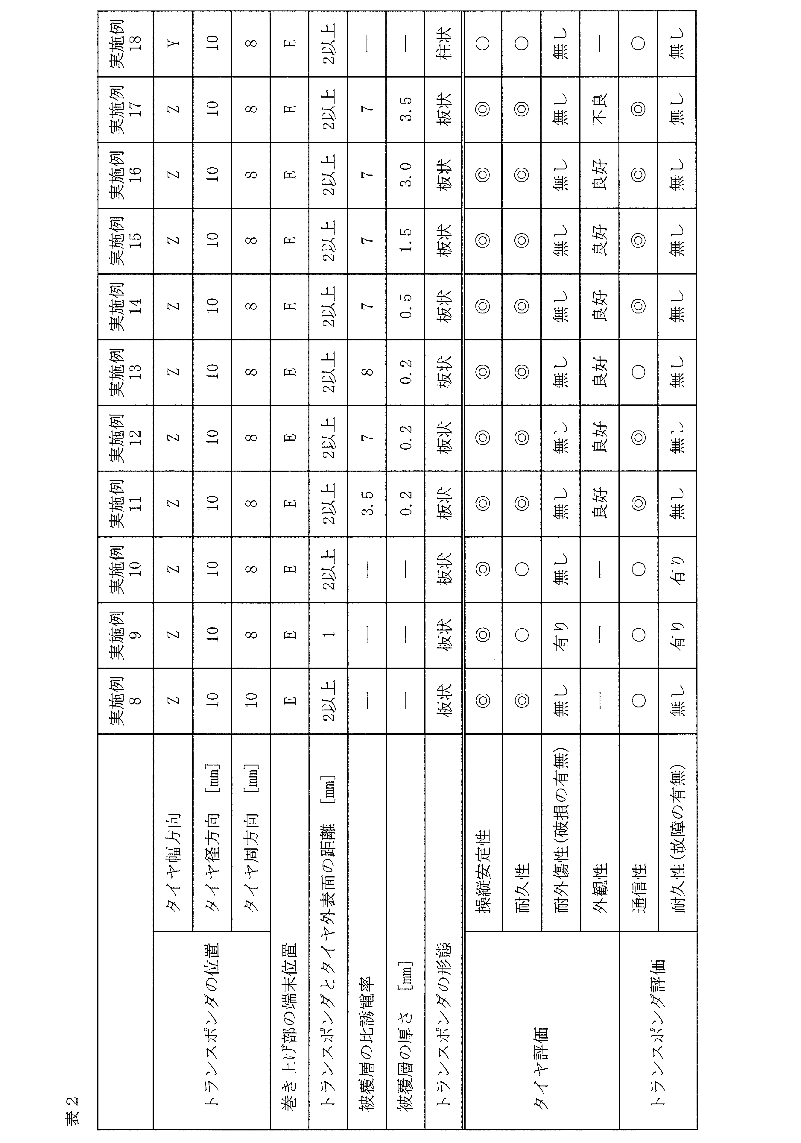
この表1及び表2から判るように、実施例1~18の空気入りタイヤは、タイヤの操縦安定性とタイヤの耐久性とトランスポンダの通信性がバランス良く改善されていた。実施例9の空気入りタイヤは、トランスポンダとタイヤ外表面の距離を短く設定したので、タイヤの耐外傷性が低下した。実施例17の空気入りタイヤは、トランスポンダを被覆する被覆層の厚さを厚く設定したので、タイヤの外観性が低下した。実施例18の空気入りタイヤは、柱状のトランスポンダを用いたので、トランスポンダの耐久性が向上し、トランスポンダを起点とする故障が無かった。
一方、比較例1においては、トランスポンダがビードフィラーとカーカス層との間に配置されていたため、タイヤの操縦安定性が悪化した。比較例1~3においては、トランスポンダがカーカス層の巻き上げ部の端末位置と同じ高さに配置されていたため、タイヤの耐久性が悪化した。比較例4においては、トランスポンダとカーカス層の巻き上げ部の端末位置との離間距離が十分に確保されていなかったため、タイヤの耐久性が悪化した。比較例5においては、トランスポンダとカーカス層の巻き上げ部の端末位置との離間距離が確保されていたが、トランスポンダがビードフィラーとカーカス層との間に配置されていたため、タイヤの操縦安定性が悪化した。
1 トレッド部
2 サイドウォール部
3 ビード部
4 カーカス層
4A 本体部
4B 巻き上げ部
5 ビードコア
6 ビードフィラー
7 ベルト層
10 ゴム層
12 サイドウォールゴム層
13 リムクッションゴム層
20 トランスポンダ
CL タイヤ中心線
P1~P3 位置
2 サイドウォール部
3 ビード部
4 カーカス層
4A 本体部
4B 巻き上げ部
5 ビードコア
6 ビードフィラー
7 ベルト層
10 ゴム層
12 サイドウォールゴム層
13 リムクッションゴム層
20 トランスポンダ
CL タイヤ中心線
P1~P3 位置
Claims (7)
- タイヤ周方向に延在して環状をなすトレッド部と、該トレッド部の両側に配置された一対のサイドウォール部と、これらサイドウォール部のタイヤ径方向内側に配置された一対のビード部とを備え、各ビード部のビードコアの外周上にビードフィラーが配置され、前記一対のビード部間に少なくとも1層のカーカス層が装架され、前記トレッド部における前記カーカス層の外周側に複数層のベルト層が配置され、前記カーカス層が前記ビードコアの廻りにタイヤ内側から外側へ巻き上げられた構造を有する空気入りタイヤにおいて、
前記カーカス層と前記サイドウォール部で前記カーカス層の外側に配置されたゴム層との間に該ゴム層に当接しながらタイヤ周方向に沿って延在するトランスポンダが埋設され、該トランスポンダが前記カーカス層の巻き上げ部の端末からタイヤ径方向に10mm以上離間して配置されていることを特徴とする空気入りタイヤ。 - 前記サイドウォール部においてタイヤ幅方向最外側に位置する前記カーカス層の巻き上げ部の端末が前記ビードフィラーの上端からタイヤ径方向外側に5mmの位置と前記ベルト層の端末からタイヤ径方向内側に15mmの位置との間に配置され、前記トランスポンダが前記ビードコアの上端からタイヤ径方向外側に15mm以上離間して配置されていることを特徴とする請求項1に記載の空気入りタイヤ。
- 前記トランスポンダの中心がタイヤ構成部材のスプライス部からタイヤ周方向に10mm以上離間して配置されていることを特徴とする請求項1又は2に記載の空気入りタイヤ。
- 前記トランスポンダの断面中心とタイヤ外表面との距離が2mm以上であることを特徴とする請求項1~3のいずれかに記載の空気入りタイヤ。
- 前記トランスポンダが被覆層により被覆され、該被覆層の比誘電率が7以下であることを特徴とする請求項1~4のいずれかに記載の空気入りタイヤ。
- 前記トランスポンダが被覆層により被覆され、該被覆層の厚さが0.5mm~3.0mmであることを特徴とする請求項1~5のいずれかに記載の空気入りタイヤ。
- 前記トランスポンダがデータを記憶するIC基板とデータを送受信するアンテナとを有し、該アンテナが螺旋状であることを特徴とする請求項1~6のいずれかに記載の空気入りタイヤ。
Priority Applications (3)
| Application Number | Priority Date | Filing Date | Title |
|---|---|---|---|
| CN202080081963.2A CN114761259B (zh) | 2019-11-27 | 2020-11-25 | 充气轮胎 |
| DE112020005235.4T DE112020005235T5 (de) | 2019-11-27 | 2020-11-25 | Luftreifen |
| US17/756,299 US20220410640A1 (en) | 2019-11-27 | 2020-11-25 | Pneumatic tire |
Applications Claiming Priority (2)
| Application Number | Priority Date | Filing Date | Title |
|---|---|---|---|
| JP2019214373A JP6683286B1 (ja) | 2019-11-27 | 2019-11-27 | 空気入りタイヤ |
| JP2019-214373 | 2019-11-27 |
Publications (1)
| Publication Number | Publication Date |
|---|---|
| WO2021106916A1 true WO2021106916A1 (ja) | 2021-06-03 |
Family
ID=70166375
Family Applications (1)
| Application Number | Title | Priority Date | Filing Date |
|---|---|---|---|
| PCT/JP2020/043765 Ceased WO2021106916A1 (ja) | 2019-11-27 | 2020-11-25 | 空気入りタイヤ |
Country Status (5)
| Country | Link |
|---|---|
| US (1) | US20220410640A1 (ja) |
| JP (1) | JP6683286B1 (ja) |
| CN (1) | CN114761259B (ja) |
| DE (1) | DE112020005235T5 (ja) |
| WO (1) | WO2021106916A1 (ja) |
Cited By (1)
| Publication number | Priority date | Publication date | Assignee | Title |
|---|---|---|---|---|
| WO2023276185A1 (ja) * | 2021-06-30 | 2023-01-05 | 株式会社ブリヂストン | タイヤ |
Families Citing this family (16)
| Publication number | Priority date | Publication date | Assignee | Title |
|---|---|---|---|---|
| JP7473800B2 (ja) * | 2020-05-28 | 2024-04-24 | 横浜ゴム株式会社 | 空気入りタイヤ |
| JP7448814B2 (ja) * | 2020-05-28 | 2024-03-13 | 横浜ゴム株式会社 | 空気入りタイヤ |
| JP7457250B2 (ja) * | 2020-06-29 | 2024-03-28 | 横浜ゴム株式会社 | 空気入りタイヤ |
| JP7545046B2 (ja) * | 2020-10-29 | 2024-09-04 | 横浜ゴム株式会社 | 空気入りタイヤ |
| JP2023006887A (ja) * | 2021-06-30 | 2023-01-18 | 株式会社ブリヂストン | タイヤ |
| JP2024036236A (ja) * | 2022-09-05 | 2024-03-15 | 株式会社ブリヂストン | 空気入りタイヤ |
| JP2024121697A (ja) | 2023-02-27 | 2024-09-06 | 住友ゴム工業株式会社 | タイヤ |
| JP2024126538A (ja) | 2023-03-07 | 2024-09-20 | 住友ゴム工業株式会社 | タイヤ |
| JP2024126537A (ja) | 2023-03-07 | 2024-09-20 | 住友ゴム工業株式会社 | タイヤ |
| JP2024126540A (ja) | 2023-03-07 | 2024-09-20 | 住友ゴム工業株式会社 | タイヤ |
| JP2024126539A (ja) | 2023-03-07 | 2024-09-20 | 住友ゴム工業株式会社 | タイヤ |
| JP2025007121A (ja) | 2023-06-30 | 2025-01-17 | 住友ゴム工業株式会社 | タイヤ |
| JP2025007122A (ja) | 2023-06-30 | 2025-01-17 | 住友ゴム工業株式会社 | タイヤ |
| JP2025007120A (ja) | 2023-06-30 | 2025-01-17 | 住友ゴム工業株式会社 | タイヤ |
| JP2025007119A (ja) | 2023-06-30 | 2025-01-17 | 住友ゴム工業株式会社 | タイヤ |
| JP2025007118A (ja) | 2023-06-30 | 2025-01-17 | 住友ゴム工業株式会社 | タイヤ |
Citations (8)
| Publication number | Priority date | Publication date | Assignee | Title |
|---|---|---|---|---|
| JP2000108621A (ja) * | 1998-10-01 | 2000-04-18 | Yokohama Rubber Co Ltd:The | 重荷重用空気入りラジアルタイヤ |
| JP2005323339A (ja) * | 2004-03-24 | 2005-11-17 | Soc D Technologie Michelin | タイヤ用無線周波数アンテナ及びそのための方法 |
| JP2007049351A (ja) * | 2005-08-09 | 2007-02-22 | Yokohama Rubber Co Ltd:The | タイヤ用電子タグ及び空気入りタイヤ |
| JP2013530874A (ja) * | 2010-07-08 | 2013-08-01 | コンパニー ゼネラール デ エタブリッスマン ミシュラン | 無線周波トランスポンダ |
| JP2013541246A (ja) * | 2010-08-11 | 2013-11-07 | コンパニー ゼネラール デ エタブリッスマン ミシュラン | タイヤ中の電子装置用のアンテナの製造方法 |
| JP2017537013A (ja) * | 2014-10-16 | 2017-12-14 | ブリヂストン アメリカズ タイヤ オペレーションズ、 エルエルシー | 接着剤で固定された埋め込み電子デバイスを有するタイヤ |
| JP6582106B1 (ja) * | 2018-10-03 | 2019-09-25 | Toyo Tire株式会社 | タイヤの製造方法 |
| JP6594508B1 (ja) * | 2018-10-03 | 2019-10-23 | Toyo Tire株式会社 | タイヤ |
Family Cites Families (10)
| Publication number | Priority date | Publication date | Assignee | Title |
|---|---|---|---|---|
| JP3113374B2 (ja) * | 1992-03-10 | 2000-11-27 | 株式会社ブリヂストン | 空気入りラジアルタイヤ |
| JP3397402B2 (ja) | 1993-11-19 | 2003-04-14 | 株式会社ブリヂストン | トランスポンダを内蔵した空気入りタイヤ |
| JP3527699B2 (ja) * | 2000-10-11 | 2004-05-17 | 住友ゴム工業株式会社 | 空気入りタイヤ |
| WO2003105509A1 (en) * | 2002-06-11 | 2003-12-18 | Societe De Technologie Michelin | A radio frequency antenna embedded in a tire |
| US8561511B2 (en) * | 2004-12-23 | 2013-10-22 | The Goodyear Tire & Rubber Company | Anvil with vacuum width adjustment |
| JP5026618B2 (ja) * | 2008-04-29 | 2012-09-12 | ミシュラン ルシェルシュ エ テクニーク ソシエテ アノニム | 面内rfidアンテナ |
| JP6102223B2 (ja) * | 2012-11-30 | 2017-03-29 | 横浜ゴム株式会社 | 空気入りタイヤ |
| JP6089641B2 (ja) * | 2012-11-30 | 2017-03-08 | 横浜ゴム株式会社 | 空気入りタイヤ |
| US9944133B2 (en) * | 2012-12-26 | 2018-04-17 | Toyo Tire & Rubber Co., Ltd. | Pneumatic tire and method of manufacturing the same |
| JP6859825B2 (ja) * | 2017-04-17 | 2021-04-14 | 横浜ゴム株式会社 | 空気入りタイヤ |
-
2019
- 2019-11-27 JP JP2019214373A patent/JP6683286B1/ja active Active
-
2020
- 2020-11-25 WO PCT/JP2020/043765 patent/WO2021106916A1/ja not_active Ceased
- 2020-11-25 CN CN202080081963.2A patent/CN114761259B/zh active Active
- 2020-11-25 US US17/756,299 patent/US20220410640A1/en active Pending
- 2020-11-25 DE DE112020005235.4T patent/DE112020005235T5/de active Pending
Patent Citations (8)
| Publication number | Priority date | Publication date | Assignee | Title |
|---|---|---|---|---|
| JP2000108621A (ja) * | 1998-10-01 | 2000-04-18 | Yokohama Rubber Co Ltd:The | 重荷重用空気入りラジアルタイヤ |
| JP2005323339A (ja) * | 2004-03-24 | 2005-11-17 | Soc D Technologie Michelin | タイヤ用無線周波数アンテナ及びそのための方法 |
| JP2007049351A (ja) * | 2005-08-09 | 2007-02-22 | Yokohama Rubber Co Ltd:The | タイヤ用電子タグ及び空気入りタイヤ |
| JP2013530874A (ja) * | 2010-07-08 | 2013-08-01 | コンパニー ゼネラール デ エタブリッスマン ミシュラン | 無線周波トランスポンダ |
| JP2013541246A (ja) * | 2010-08-11 | 2013-11-07 | コンパニー ゼネラール デ エタブリッスマン ミシュラン | タイヤ中の電子装置用のアンテナの製造方法 |
| JP2017537013A (ja) * | 2014-10-16 | 2017-12-14 | ブリヂストン アメリカズ タイヤ オペレーションズ、 エルエルシー | 接着剤で固定された埋め込み電子デバイスを有するタイヤ |
| JP6582106B1 (ja) * | 2018-10-03 | 2019-09-25 | Toyo Tire株式会社 | タイヤの製造方法 |
| JP6594508B1 (ja) * | 2018-10-03 | 2019-10-23 | Toyo Tire株式会社 | タイヤ |
Cited By (4)
| Publication number | Priority date | Publication date | Assignee | Title |
|---|---|---|---|---|
| WO2023276185A1 (ja) * | 2021-06-30 | 2023-01-05 | 株式会社ブリヂストン | タイヤ |
| CN117377576A (zh) * | 2021-06-30 | 2024-01-09 | 株式会社普利司通 | 轮胎 |
| JP7573494B2 (ja) | 2021-06-30 | 2024-10-25 | 株式会社ブリヂストン | タイヤ |
| EP4364966A4 (en) * | 2021-06-30 | 2024-11-13 | Bridgestone Corporation | PNEUMATIC |
Also Published As
| Publication number | Publication date |
|---|---|
| JP2021084510A (ja) | 2021-06-03 |
| CN114761259A (zh) | 2022-07-15 |
| US20220410640A1 (en) | 2022-12-29 |
| JP6683286B1 (ja) | 2020-04-15 |
| CN114761259B (zh) | 2024-03-12 |
| DE112020005235T5 (de) | 2022-09-01 |
Similar Documents
| Publication | Publication Date | Title |
|---|---|---|
| JP2021084510A (ja) | 空気入りタイヤ | |
| JP6667045B1 (ja) | 空気入りタイヤ | |
| JP6683287B1 (ja) | 空気入りタイヤ | |
| JP2021127088A (ja) | 空気入りタイヤ | |
| WO2022004477A1 (ja) | 空気入りタイヤ | |
| JP2021127087A (ja) | 空気入りタイヤ | |
| JP2021112932A (ja) | 空気入りタイヤ | |
| WO2021166792A1 (ja) | 空気入りタイヤ | |
| WO2022004479A1 (ja) | 空気入りタイヤ | |
| WO2021241202A1 (ja) | 空気入りタイヤ | |
| JP2021127093A (ja) | 空気入りタイヤ | |
| JP7279671B2 (ja) | 空気入りタイヤ | |
| JP2021127092A (ja) | 空気入りタイヤ | |
| JP2021127074A (ja) | 空気入りタイヤ | |
| CN116075828A (zh) | 充气轮胎 | |
| WO2021241203A1 (ja) | 空気入りタイヤ | |
| WO2021166794A1 (ja) | 空気入りタイヤ | |
| WO2021166800A1 (ja) | 空気入りタイヤ | |
| WO2021166798A1 (ja) | 空気入りタイヤ | |
| JP2021187267A (ja) | 空気入りタイヤ | |
| JP2021127091A (ja) | 空気入りタイヤ | |
| JP2021127090A (ja) | 空気入りタイヤ | |
| WO2022004478A1 (ja) | 空気入りタイヤ | |
| WO2021166793A1 (ja) | 空気入りタイヤ | |
| JP2021127089A (ja) | 空気入りタイヤ |
Legal Events
| Date | Code | Title | Description |
|---|---|---|---|
| 121 | Ep: the epo has been informed by wipo that ep was designated in this application |
Ref document number: 20893089 Country of ref document: EP Kind code of ref document: A1 |
|
| 122 | Ep: pct application non-entry in european phase |
Ref document number: 20893089 Country of ref document: EP Kind code of ref document: A1 |