WO2021100845A1 - ロボットシステム及びその運転方法 - Google Patents
ロボットシステム及びその運転方法 Download PDFInfo
- Publication number
- WO2021100845A1 WO2021100845A1 PCT/JP2020/043354 JP2020043354W WO2021100845A1 WO 2021100845 A1 WO2021100845 A1 WO 2021100845A1 JP 2020043354 W JP2020043354 W JP 2020043354W WO 2021100845 A1 WO2021100845 A1 WO 2021100845A1
- Authority
- WO
- WIPO (PCT)
- Prior art keywords
- arm
- hand
- robot system
- robot
- control device
- Prior art date
- Legal status (The legal status is an assumption and is not a legal conclusion. Google has not performed a legal analysis and makes no representation as to the accuracy of the status listed.)
- Ceased
Links
Images


Classifications
-
- B—PERFORMING OPERATIONS; TRANSPORTING
- B25—HAND TOOLS; PORTABLE POWER-DRIVEN TOOLS; MANIPULATORS
- B25J—MANIPULATORS; CHAMBERS PROVIDED WITH MANIPULATION DEVICES
- B25J15/00—Gripping heads and other end effectors
- B25J15/0052—Gripping heads and other end effectors multiple gripper units or multiple end effectors
- B25J15/0061—Gripping heads and other end effectors multiple gripper units or multiple end effectors mounted on a modular gripping structure
-
- B—PERFORMING OPERATIONS; TRANSPORTING
- B65—CONVEYING; PACKING; STORING; HANDLING THIN OR FILAMENTARY MATERIAL
- B65G—TRANSPORT OR STORAGE DEVICES, e.g. CONVEYORS FOR LOADING OR TIPPING, SHOP CONVEYOR SYSTEMS OR PNEUMATIC TUBE CONVEYORS
- B65G47/00—Article or material-handling devices associated with conveyors; Methods employing such devices
- B65G47/74—Feeding, transfer, or discharging devices of particular kinds or types
- B65G47/90—Devices for picking-up and depositing articles or materials
- B65G47/91—Devices for picking-up and depositing articles or materials incorporating pneumatic, e.g. suction, grippers
-
- B—PERFORMING OPERATIONS; TRANSPORTING
- B25—HAND TOOLS; PORTABLE POWER-DRIVEN TOOLS; MANIPULATORS
- B25J—MANIPULATORS; CHAMBERS PROVIDED WITH MANIPULATION DEVICES
- B25J15/00—Gripping heads and other end effectors
- B25J15/06—Gripping heads and other end effectors with vacuum or magnetic holding means
- B25J15/0616—Gripping heads and other end effectors with vacuum or magnetic holding means with vacuum
-
- B—PERFORMING OPERATIONS; TRANSPORTING
- B65—CONVEYING; PACKING; STORING; HANDLING THIN OR FILAMENTARY MATERIAL
- B65G—TRANSPORT OR STORAGE DEVICES, e.g. CONVEYORS FOR LOADING OR TIPPING, SHOP CONVEYOR SYSTEMS OR PNEUMATIC TUBE CONVEYORS
- B65G47/00—Article or material-handling devices associated with conveyors; Methods employing such devices
- B65G47/74—Feeding, transfer, or discharging devices of particular kinds or types
- B65G47/90—Devices for picking-up and depositing articles or materials
- B65G47/907—Devices for picking-up and depositing articles or materials with at least two picking-up heads
Definitions
- the present invention relates to a robot system and its operation method.
- a robot device is known for the purpose of accurately positioning a plurality of parts at the same time (see, for example, Patent Document 1).
- the robot device disclosed in Patent Document 1 is supported by a pinion that rotates about an axis by a rotary drive source (servomotor), a link mechanism (pantograph mechanism) that is opened and closed by a pair of racks, and a link mechanism.
- a component positioning device having a plurality of holding portions is provided at the tip of the robot arm. Then, the holding portions are positioned by changing the distance between the adjacent holding portions according to the opening / closing operation of the link mechanism.
- the present invention solves the above-mentioned conventional problems, and an object of the present invention is to provide a robot system and an operation method thereof capable of holding and transporting a work heavier than a conventional robot system. There is.
- the robot system includes a plurality of first holding portions, a first link mechanism configured to change the interval between the plurality of first holding portions, and a first link mechanism.
- a first hand having a first engaging portion, a plurality of second holding portions, a second link mechanism configured to vary the distance between the plurality of second holding portions, and a second engaged portion.
- the control device includes a second hand having a joint portion, a first arm to which the first hand is connected, a second arm to which the second hand is connected, and a control device.
- the distance between the first holding part and the second holding part can be changed without providing an actuator for changing the distance between the first holding part and the second holding part in the first hand and the second hand. it can. Further, since the actuator for changing the distance between the first holding portion and the second holding portion is not provided, it is possible to hold and convey a work having a heavier weight as compared with the conventional robot system.
- the robot system includes a plurality of first holding portions and a first link mechanism configured to change the interval between the plurality of first holding portions.
- a first hand having an engaging portion, a plurality of second holding portions, a second link mechanism configured to vary the distance between the plurality of second holding portions, an engaged portion, and the like.
- a second hand having the above, a first arm to which the first hand is connected, and a second arm to which the second hand is connected are provided, and the engaging portion engages with the engaged portion.
- the distance between the first holding part and the second holding part can be changed without providing an actuator for changing the distance between the first holding part and the second holding part in the first hand and the second hand. it can. Further, since the actuator for changing the distance between the first holding portion and the second holding portion is not provided, it is possible to hold and convey a work having a heavier weight as compared with the conventional robot system.
- the first hand and the second hand are not provided with an actuator for changing the distance between the first holding portion and the second holding portion, and thus the conventional robot system. It is possible to hold and transport a work having a large weight as compared with the above.
- FIG. 1 is a schematic diagram showing a schematic configuration of a robot system according to the first embodiment.
- FIG. 2 is a functional block diagram schematically showing the configuration of the robot control device shown in FIG.
- FIG. 3 is a schematic view showing a schematic configuration of the upper surface of the first hand in the robot shown in FIG.
- FIG. 4 is a schematic view showing a schematic configuration of the back surface of the first hand in the robot shown in FIG.
- FIG. 5 is a schematic diagram showing a schematic configuration of a main part of the first hand in the robot shown in FIG.
- FIG. 6A is a flowchart showing an example of the operation of the robot system according to the first embodiment.
- FIG. 6B is a flowchart showing an example of the operation of the robot system according to the first embodiment.
- FIG. 6A is a flowchart showing an example of the operation of the robot system according to the first embodiment.
- FIG. 6B is a flowchart showing an example of the operation of the robot system according to the first embodiment.
- FIG. 7 is a schematic view showing a state of the robot when the robot system is operating according to the flowcharts shown in FIGS. 6A and 6B.
- FIG. 8 is a flowchart showing an example of the operation of the robot system according to the first embodiment.
- FIG. 9 is a schematic view showing a state of the robot when the robot system is operating according to the flowcharts shown in FIGS. 6A and 6B.
- FIG. 10 is a schematic view showing a state of the robot when the robot system is operating according to the flowcharts shown in FIGS. 6A and 6B.
- FIG. 11 is a schematic view showing a state of the robot when the robot system is operating according to the flowcharts shown in FIGS. 6A and 6B.
- FIG. 12 is a schematic diagram showing a schematic configuration of the robot system according to the second embodiment.
- the robot system according to the first embodiment has a plurality of first holding portions, a first link mechanism configured to change the interval between the plurality of first holding portions, and an engaging portion.
- a second hand having a first hand, a plurality of second holding portions, a second link mechanism configured to vary the distance between the plurality of second holding portions, and an engaged portion.
- a first arm to which the first hand is connected, a second arm to which the second hand is connected, and a control device are provided, and the control device is provided so that the engaged portion engages with the engaged portion.
- the first arm and / or the second arm is operated, and after (A), the first arm is operated so as to change the interval between the plurality of first holding portions (B). Is configured to run.
- control device further executes (C) to operate the second arm so as to change the interval between the plurality of second holding portions. It may be configured as follows.
- the first hand further has an engaged portion
- the second hand further has an engaged portion
- the control device has the first in (A).
- the first arm and / or the first arm so that the engaging portion of the first hand engages with the engaged portion of the second hand and the engaging portion of the second hand engages with the engaged portion of the first hand. It may be configured to operate the two arms.
- FIG. 1 is a schematic diagram showing a schematic configuration of a robot system according to the first embodiment.
- FIG. 2 is a functional block diagram schematically showing the configuration of the robot control device shown in FIG.
- a horizontal articulated dual-arm robot will be described as a robot constituting the robot system according to the first embodiment, but the robot is not limited thereto.
- the robot constituting the robot system according to the first embodiment other robots such as a horizontal articulated type and a vertical articulated type may be adopted.
- the robot system 100 controls the carriage 12, the first arm 13A, the second arm 13B, and the vacuum generator 25 arranged in the carriage 12.
- a robot 101 having a device 110 and a device 110 is provided. Further, a control device 110 is arranged in the carriage 12.
- control device 110 and the vacuum generator 25 are arranged inside the carriage 12, but the present invention is not limited to this, and these devices are arranged outside the carriage 12. It may have been done.
- the vacuum generator 25 is connected to the suction portion 8 of the first arm 13A and the second arm 13B, which will be described later, by the pipe 93A and the pipe 93B.
- the vacuum generator 25 is a device that creates a negative pressure in the suction unit 8, and for example, a vacuum pump, CONVUM (registered trademark), or the like may be used.
- the on-off valve 94A and the on-off valve 94B are provided in the pipe 93A and the pipe 93B, respectively.
- the on-off valve 94A and the on-off valve 94B open or close the pipe 93A and the pipe 93B, respectively, so that the suction portion (first holding portion or the second holding portion) 8 can attract (hold) the work 103 and release the work 103. Will be done.
- the operation of the vacuum generator 25 and the opening / closing operation of the on-off valve 94A and the on-off valve 94B are controlled by the control device 110.
- the base shaft 16 is fixed to the upper surface of the dolly 12.
- the base shaft 16 is provided with a first arm 13A and a second arm 13B so as to be rotatable around a rotation axis L1 passing through the axis of the base shaft 16.
- the first arm 13A and the second arm 13B are provided so as to have a height difference in the vertical direction.
- the first arm 13A and the second arm 13B are configured to be able to operate independently or in relation to each other.
- the first arm 13A has a first arm portion 15A, a first wrist portion 17A, a first hand 18A, and a first mounting portion 20A.
- the second arm 13B has a second arm portion 15B, a second wrist portion 17B, a second hand 18B, and a second mounting portion 20B. Since the basic configuration of the second arm 13B is the same as that of the first arm 13A, detailed description thereof will be omitted.
- the first arm portion 15A is composed of a substantially rectangular parallelepiped first link 5a and a second link 5b.
- the first link 5a is provided with a rotary joint J1 at the base end portion and a rotary joint J2 at the tip end portion.
- the second link 5b is provided with a linear motion joint J3 at the tip end portion.
- the base end of the first link 5a is connected to the base shaft 16 via the rotary joint J1, and the first link 5a can be rotated around the rotary axis L1 by the rotary joint J1. Further, the base end portion of the second link 5b is connected to the tip end portion of the first link 5a via the rotary joint J2, and the second link 5b can be rotated around the rotation axis L2 by the rotary joint J2.
- the first wrist portion 17A is connected to the tip of the second link 5b via a linear motion joint J3 so as to be vertically movable with respect to the second link 5b.
- a rotary joint J4 is provided at the lower end of the first wrist portion 17A, and a first mounting portion 20A is provided at the lower end of the rotary joint J4.
- the first mounting portion 20A is configured so that the first hand 18A can be attached and detached.
- the first mounting portion 20A has a pair of rod members whose intervals are adjustable, and the first hand 18A is sandwiched between the pair of rod members.
- the first hand 18A can be attached to the first wrist unit 17A.
- the first hand 18A can be rotated around the rotation axis L3 by the rotation joint J4.
- the tip of the rod member may be bent.
- the structure of the first hand 18A will be described later.
- each of the joints J1 to J4 of the first arm 13A and the second arm 13B is provided with a drive motor as an example of an actuator that relatively rotates or raises and lowers two members to which the joints are connected.
- the drive motor may be, for example, a servomotor that is servo-controlled by the control device 110.
- each of the joints J1 to J4 has a rotation sensor (not shown) that detects the rotation position of the drive motor, and a current sensor (not shown) that detects the current that controls the rotation of the drive motor. Is provided.
- the rotation sensor may be, for example, an encoder.
- the control device 110 includes an arithmetic processor 110a, a storage device 110b, and an input device 110c.
- the arithmetic processor 110a is composed of a microprocessor, a CPU, and the like, and controls various operations of the robot system 100 by reading and executing software such as a basic program stored in the storage device 110b.
- the storage device 110b stores information such as a basic program and various fixed data.
- the storage device 110b does not have to be a single device, and may be configured as a plurality of storage devices (for example, a random access memory and a hard disk drive).
- the arithmetic processing unit 110a is composed of a microcomputer, at least a part of the storage device 110b may be configured as an internal memory of the microcomputer or may be configured as an independent memory.
- the input device 110c is capable of inputting various parameters related to the control of the robot system 100, other data, and the like to the arithmetic processing device 110a, and is a known input device such as a keyboard, a touch panel, and a button switch group. It is configured.
- data such as the holding condition of the work 103 (weight of the work 103, etc.), the number of works 103 to be stored in the container, and the like may be input by the input device 110c.
- the control device 110 may be composed of a single control device 110 for centralized control, or may be composed of a plurality of control devices 110 for distributed control in cooperation with each other. Further, the control device 110 may be composed of a microcomputer, an MPU, a PLC (Programmable Logic Controller), a logic circuit, or the like.
- a microcomputer an MPU, a PLC (Programmable Logic Controller), a logic circuit, or the like.
- the first hand 18A of the first arm 13A will be described in detail with reference to FIGS. 3 to 5. Since the second hand 18B of the second arm 13B has the same basic configuration as the first hand 18A, detailed description thereof will be omitted.
- FIG. 3 is a schematic view showing a schematic configuration of the upper surface of the first hand in the robot shown in FIG.
- FIG. 4 is a schematic view showing a schematic configuration of the back surface of the first hand in the robot shown in FIG.
- FIG. 5 is a schematic diagram showing a schematic configuration of a main part of the first hand in the robot shown in FIG.
- FIGS. 3 to 5 the front-back direction, the left-right direction, and the up-down direction of the robot (first hand) are represented as the front-back direction, the left-right direction, and the up-down direction in the figure, respectively. Further, in FIGS. 3 and 5, the description of the work is omitted.
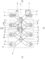
- the first hand 18A of the first arm 13A has a main body 81, a base member 82, a link mechanism (first link mechanism) 83, and a plurality of suction portions 8A to 8H.
- the adsorption units 8A to 8H are not distinguished, they may be referred to as the adsorption unit 8.
- the main body 81 is composed of a housing, and a base member 82 is provided at the lower end portion thereof.
- the base member 82 is formed in a substantially T shape when viewed from the vertical direction.
- a link mechanism 83 configured to be able to advance and retreat in the left-right direction is arranged below the base member 82.
- the first mechanism 84 is provided at the right end of the upper end surface of the base member 82.
- the first mechanism 84 has a drum 84A and a tape 84B.
- the drum 84A is equipped with a mainspring (winding spring; not shown).
- the base end portion of the tape 84B is connected to the mainspring, and the tip end portion of the tape 84B is fixed to the first fixing member 71.
- the first fixing member 71 is connected to the link mechanism 83 via the first guide member 31 of the linear guide 30, which will be described later. As a result, the extended link mechanism 83 can be retracted by the spring force of the mainspring.
- a first stopper 41 is provided at a substantially central portion of the upper end surface of the base member 82.
- the first stopper 41 has a substantially L-shaped second fixing member 42 and a linear actuator 43.
- the linear actuator 43 has a cylinder, a piston, and a drive mechanism for moving the piston forward and backward.
- the tip surface of the linear actuator 43 comes into contact with the main surface of the tape 84B and presses the tape 84B on the tip surface of the linear actuator 43 and the main surface of the second fixing member 42. It is configured to be sandwiched.
- the link mechanism 83 can be set to an arbitrary length (maintained at an arbitrary length), and the distance between the suction portions 8 and 8 adjacent to each other in the left-right direction can be set to an arbitrary length. ..
- the linear actuator 43 may be configured such that the frictional force generated by sandwiching the tape 84B is larger than the spring force of the mainspring, a small motor can be used as the drive mechanism. it can. Therefore, it is possible to suppress an increase in the weight of the first hand 18A, and it is possible to hold and transport a work having a heavier weight than the conventional robot system.
- a third fixing member 73 and a linear guide 30 are provided on the lower end surface of the base member 82.
- the tip of the first shaft member 831 of the link mechanism 83, which will be described later, is fitted to the third fixing member 73.
- the linear guide 30 has a first guide member 31, a second guide member 32, and a rail member 33.
- the rail member 33 is formed so as to extend in the left-right direction, and is configured to guide the first guide member 31 and the second guide member 32.
- a second stopper 52 is provided on the front surface of the first guide member 31 and the second guide member 32.
- the second stopper 52 has a rod-shaped first member 52A and a box-shaped second member 52B, and the tip of the first member 52A comes into contact with the second member 52B to stop the tape 84B from regressing. It is configured to do. Further, the length of the first member 52A is set in advance so that the adjacent suction portions 8 and 8 do not come into contact with each other.
- the tip of the second shaft member 832 of the link mechanism 83 which will be described later, is fitted to the first guide member 31, and the tip of the third shaft member 833 of the link mechanism 83 is fitted to the second guide member 32. The parts are fitted.
- the link mechanism 83 employs a pantograph mechanism and has strip-shaped link members 83A to 83F and first shaft members 831 to third shaft members 833.
- a rail mechanism may be adopted, and a configuration in which the distance between the two suction portions 8 and 8 may be changed may be adopted.
- the link member 83A and the link member 83B are arranged in an X shape when viewed from the vertical direction, and the first shaft member 831 is inserted at the intersection of the link member 83A and the link member 83B.
- the link member 83C and the link member 83D are also arranged in an X shape when viewed from the vertical direction, and the second shaft member 832 is inserted at the intersection of the link member 83C and the link member 83D. ..
- the link member 83E and the link member 83F are also arranged in an X shape when viewed from the vertical direction, and a third shaft member 833 is inserted at the intersection of the link member 83E and the link member 83F.
- Each of the link member 83A to the link member 83D is bent at the right end portion, and the suction portion 8 is provided at the right end portion (base end). Further, the link member 83E and the link member 83F are bent at both the right end portion and the left end portion, respectively, and the suction portion 8 is provided at the right end end (base end), respectively. Further, a truncated cone-shaped suction pad 80 is provided at the tip end portion (lower end portion) of the suction portion 8.
- the tip of the link member 83A is rotatably connected to the bent portion of the link member 83D by the shaft member 830A.
- the tip end portion of the link member 83B is rotatably connected to the bent portion of the link member 83C by the shaft member 830B.
- the tip of the link member 83C is rotatably connected to the right bent portion of the link member 83F by the shaft member 830C.
- the tip end portion of the link member 83D is rotatably connected to the right bending portion of the link member 83E by the shaft member 830D.
- An L-shaped first connecting member 91 is provided at the left bending portion of the link member 83F.
- a pin-shaped first engaging portion (engaging portion) 91A is provided at the tip of the first connecting member 91.
- an L-shaped second connecting member 92 is provided at the left bending portion of the link member 83E.
- a hole is formed in the main surface of the second connecting member 92, and the hole constitutes the first engaged portion (engaged portion) 91B.
- a second engaging portion (engaging portion) 92A is provided in place of the first engaging portion 91A, and the first engaged portion is provided.
- a second engaged portion (engaged portion) 92B is provided.
- the link mechanism (first link mechanism) 83 of the first hand 18A constitutes the second link mechanism.
- a form in which the work 103 is sucked and held by the suction portion 8 is adopted, but the present invention is not limited to this.
- a form in which the work 103 is gripped by a pair of claws or the like arranged in the front-rear direction may be adopted.
- the suction portions 8A to 8D (8E to 8H) are arranged so as to be arranged in the left-right direction. Is adopted. Therefore, when a plurality of works 103 are arranged so as to be arranged in the front-rear direction, a configuration is adopted in which the suction portions 8A to 8D (8E to 8H) are arranged so as to be arranged in the front-rear direction.
- the first hand 18A has the first engaging portion 91A and the first engaged portion 91B
- the second hand 18B has the second engaging portion 92A
- a form having the second engaged portion 92B is adopted, but the present invention is not limited to this.
- a form in which the first hand 18A has the first engaging portion 91A and the second hand 18B has the second engaged portion 92B may be adopted.
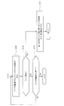
- FIGS. 6A and 6B are flowcharts showing an example of the operation of the robot system according to the first embodiment.
- 7 to 11 are schematic views showing a state of the robot when the robot system is operating according to the flowcharts shown in FIGS. 6A and 6B.
- the first hand 18A and the second hand 18B are in the initial state in which the first member 52A is in contact with the second member 52B.
- the first stopper 41 is operating when the first hand 18A and the second hand 18B are in the initial state. That is, it is assumed that the tape 84B is sandwiched between the tip of the linear actuator 43 of the first stopper 41 and the second fixing member 42.
- control device 110 instruction information indicating that the operation of holding and transporting the work 103 indicated by the alternate long and short dash line is executed via the input device 110c.
- control device 110 executes the following operations.
- the first engaging portion 91A of the first hand 18A and the second engaged portion 92B of the second hand 18B are engaged with each other, and the second engaging portion 92A of the second hand 18B and the second engaged portion 92B are engaged.
- the first arm 13A and / or the second arm 13B is operated so that the first engaged portion 91B of the one hand 18A is engaged (step S101).
- the control device 110 operates the first arm 13A and / or the second arm 13B so that the first hand 18A and the second hand 18B are close to each other.
- the pin-shaped first engaging portion 91A and the second engaging portion 92A are inserted into the holes forming the second engaged portion 92B and the first engaged portion 91B, respectively.
- the first arm 13A and / or the second arm 13B is operated.
- control device 110 releases the first stopper 41 of the first hand 18A (step S102). Specifically, the control device 110 drives the linear actuator 43 so that the tip of the piston of the first stopper 41 retracts, and separates the tip of the piston from the tape 84B.
- control device 110 operates the first arm 13A so as to change the interval between the adjacent suction units 8 and 8 (step S103). That is, in the robot system 100 according to the first embodiment, as an actuator, the first arm 13A holding the first hand 18A changes the interval between the adjacent suction portions 8 and 8 of the first hand 18A. It is functioning.
- control device 110 operates the first stopper 41 of the first hand 18A when the distance between the suction portions 8 and 8 becomes a length that can correspond to the size of the work 103 (step S104). ..
- the interval between the suction portions 8 and 8, which can correspond to the size of the work 103, is set in advance by an experiment or the like, and the interval is stored in the storage device 110b.
- control device 110 releases the first stopper 41 of the second hand 18B (step S105).
- control device 110 operates the second arm 13B so as to change the interval between the adjacent suction units 8 and 8 (step S106).
- the control device 110 operates the first stopper 41 of the second hand 18B when the distance between the suction portions 8 and 8 becomes a length that can correspond to the size of the work 103 (step S107).
- control device 110 engages with the first engaging portion 91A of the first hand 18A and the second engaged portion 92B of the second hand 18B, and with the second engaging portion 92A of the second hand 18B.
- the first arm 13A and / or the second arm 13B is operated so as to disengage the first hand 18A from the first engaged portion 91B (step S108).
- control device 110 operates the robot 101 (first arm 13A and second arm 13B) so as to convey the work 103 (step S109).
- control device 110 operates the first arm 13A and the second arm 13B so that the first hand 18A and the second hand 18B are located above the work 103.
- control device 110 operates the vacuum generator 25 to open the valve bodies of the on-off valve 94A and the on-off valve 94B.
- control device 110 operates the first arm 13A and the second arm 13B so that the suction unit 8 comes into contact with the work 103. As a result, the suction unit 8 can suck and hold the work 103.
- control device 110 operates the first arm 13A and the second arm 13B to convey the work 103 to a predetermined position set in advance. Then, the control device 110 closes the valve bodies of the on-off valve 94A and the on-off valve 94B, and releases the work 103.
- control device 110 determines whether or not a command for changing the type, size, weight, etc. of the work 103 being conveyed from the input device 110c has been input (step S110). At this time, the control device 110 determines whether or not a command for transporting a work having a width larger than that of the work 103 shown in FIG. 7 has been input from the input device 110c, such as the work 103A shown in FIG. judge.
- step S110 When the control device 110 determines that a command for changing the type of the work 103 being conveyed from the input device 110c has been input (Yes in step S110), the first hand 18A and the second hand 18B are the first. The stopper 41 is released, the first hand 18A and the second hand 18B are returned to the initial state (step S111), and the process returns to the process of step S101.
- control device 110 determines that the command for changing the type or the like of the work 103 being conveyed from the input device 110c has not been input (No in step S110), has the transfer of the work 103 been completed? It is determined whether or not (step S112).
- control device 110 determines that the transfer of the work 103 has not been completed (No in step S112), the control device 110 repeats the processes of steps S109 to S112 until it determines that the transfer of the work 103 has been completed.
- control device 110 determines that the transfer of the work 103 is completed (Yes in step S112), the control device 110 ends this program.
- the intervals of the suction portions 8 are changed between the first hand 18A and the second hand 18B. Since no actuator is provided for this purpose, it is possible to hold and transport a work that is heavier than that of a conventional robot system.
- the linear actuator 43 provided in the first hand 18A and the second hand 18B has a frictional force generated by sandwiching the tape 84B as a spring of the mainspring. It is configured to be greater than the force.
- a small motor can be used as the drive mechanism of the linear actuator 43.
- the second stopper 52 is provided on the first hand 18A and the second hand 18B. As a result, when the first stopper 41 is released, the contact between the adjacent suction portions 8 and 8 can be suppressed.
- the robot system according to the second embodiment includes a first robot having a first arm and a second robot having a second arm in the robot system according to the first embodiment.
- FIG. 12 is a schematic diagram showing a schematic configuration of the robot system according to the second embodiment.
- the robot system 100 includes two robots 101A and 101B.
- the robot 101A has a first arm 13A to which the first hand 18A is connected, and the robot 101B has a second arm 13B to which the second hand 18B is connected.
- the robots 101A and 101B employ a known vertical articulated robot in the second embodiment, detailed description thereof will be omitted. Further, in the second embodiment, the vertical articulated robot is adopted, but the present invention is not limited to this, and other robots such as the horizontal articulated robot may be adopted.
- the mode in which the robots 101A and 101B are controlled by one control device 110 is adopted, but the present invention is not limited to this, and the robots 101A and 101B are controlled by a plurality of control devices 110. You may adopt the form of.
- the robot system and its operation method according to the present invention are useful in the field of industrial robots because they can hold and transport heavier workpieces than conventional robot systems.
Landscapes
- Engineering & Computer Science (AREA)
- Mechanical Engineering (AREA)
- Robotics (AREA)
- Manipulator (AREA)
Priority Applications (3)
| Application Number | Priority Date | Filing Date | Title |
|---|---|---|---|
| DE112020005682.1T DE112020005682B4 (de) | 2019-11-20 | 2020-11-20 | Robotersystem und verfahren zum betrieb desselben |
| CN202080080568.2A CN114761186B (zh) | 2019-11-20 | 2020-11-20 | 机器人系统及其运转方法 |
| US17/778,016 US12195287B2 (en) | 2019-11-20 | 2020-11-20 | Robot system and method of operating the same |
Applications Claiming Priority (2)
| Application Number | Priority Date | Filing Date | Title |
|---|---|---|---|
| JP2019-209743 | 2019-11-20 | ||
| JP2019209743A JP7278198B2 (ja) | 2019-11-20 | 2019-11-20 | ロボットシステム及びその運転方法 |
Publications (1)
| Publication Number | Publication Date |
|---|---|
| WO2021100845A1 true WO2021100845A1 (ja) | 2021-05-27 |
Family
ID=75963260
Family Applications (1)
| Application Number | Title | Priority Date | Filing Date |
|---|---|---|---|
| PCT/JP2020/043354 Ceased WO2021100845A1 (ja) | 2019-11-20 | 2020-11-20 | ロボットシステム及びその運転方法 |
Country Status (6)
| Country | Link |
|---|---|
| US (1) | US12195287B2 (https=) |
| JP (1) | JP7278198B2 (https=) |
| CN (1) | CN114761186B (https=) |
| DE (1) | DE112020005682B4 (https=) |
| TW (1) | TWI738572B (https=) |
| WO (1) | WO2021100845A1 (https=) |
Families Citing this family (1)
| Publication number | Priority date | Publication date | Assignee | Title |
|---|---|---|---|---|
| KR20230051377A (ko) * | 2021-10-08 | 2023-04-18 | 삼성전자주식회사 | 기판 이송 장치 및 이를 이용한 기판 이송 방법 |
Citations (2)
| Publication number | Priority date | Publication date | Assignee | Title |
|---|---|---|---|---|
| JP2015039768A (ja) * | 2013-08-20 | 2015-03-02 | 大森機械工業株式会社 | 集積装置 |
| JP2019147196A (ja) * | 2018-02-26 | 2019-09-05 | ファナック株式会社 | ロボットハンド、ロボットおよびロボットハンドのハンド幅調整方法 |
Family Cites Families (14)
| Publication number | Priority date | Publication date | Assignee | Title |
|---|---|---|---|---|
| US3610673A (en) | 1969-10-20 | 1971-10-05 | Svenska Cellulosa Ab | Arrangement for handling objects |
| JPH07102844B2 (ja) | 1993-05-12 | 1995-11-08 | 東洋水産株式会社 | 自動箱詰め装置 |
| JP3577028B2 (ja) | 2001-11-07 | 2004-10-13 | 川崎重工業株式会社 | ロボットの協調制御システム |
| US20050005513A1 (en) | 2003-06-30 | 2005-01-13 | Smithers-Oasis | Floral display system |
| DE102004012592B4 (de) | 2004-03-12 | 2006-03-09 | Daimlerchrysler Ag | Verfahren zum lagegenauen Positionieren von Bauteilen und hierzu geeignete Positioniervorrichtung |
| CZ309347B6 (cs) | 2012-07-11 | 2022-09-14 | České vysoké učení technické v Praze | Způsob určení polohy středu obráběcího nástroje uchyceného v kooperující úchopné hlavici a tato hlavice |
| DE102013220798A1 (de) | 2013-10-15 | 2015-04-16 | Kuka Laboratories Gmbh | Verfahren zum Handhaben von Objekten mittels wenigstens zweier Industrieroboter, und zugehöriger Industrieroboter |
| CN103707311B (zh) * | 2013-12-23 | 2015-08-05 | 苏州博众精工科技有限公司 | 一种可变节距伸缩夹爪 |
| CN105459087B (zh) * | 2015-12-30 | 2017-10-31 | 苏州澳昆智能机器人技术有限公司 | 变距柔性机器人工夹具 |
| JP6838895B2 (ja) * | 2016-07-05 | 2021-03-03 | 川崎重工業株式会社 | ワーク搬送装置およびその運転方法 |
| JP6789728B2 (ja) * | 2016-08-31 | 2020-11-25 | 川崎重工業株式会社 | ロボット及びその運転方法 |
| JP2019000927A (ja) | 2017-06-13 | 2019-01-10 | 株式会社豊田自動織機 | 部品位置決め装置及びロボット装置 |
| CN207930664U (zh) * | 2018-03-12 | 2018-10-02 | 重庆交通大学 | 一种双臂式搬运机械手 |
| CN108890668A (zh) * | 2018-06-13 | 2018-11-27 | 天津大学 | 一种可伸缩和旋转的末端执行器 |
-
2019
- 2019-11-20 JP JP2019209743A patent/JP7278198B2/ja active Active
-
2020
- 2020-11-20 WO PCT/JP2020/043354 patent/WO2021100845A1/ja not_active Ceased
- 2020-11-20 TW TW109140710A patent/TWI738572B/zh not_active IP Right Cessation
- 2020-11-20 DE DE112020005682.1T patent/DE112020005682B4/de active Active
- 2020-11-20 CN CN202080080568.2A patent/CN114761186B/zh active Active
- 2020-11-20 US US17/778,016 patent/US12195287B2/en active Active
Patent Citations (2)
| Publication number | Priority date | Publication date | Assignee | Title |
|---|---|---|---|---|
| JP2015039768A (ja) * | 2013-08-20 | 2015-03-02 | 大森機械工業株式会社 | 集積装置 |
| JP2019147196A (ja) * | 2018-02-26 | 2019-09-05 | ファナック株式会社 | ロボットハンド、ロボットおよびロボットハンドのハンド幅調整方法 |
Also Published As
| Publication number | Publication date |
|---|---|
| JP2021079496A (ja) | 2021-05-27 |
| CN114761186A (zh) | 2022-07-15 |
| JP7278198B2 (ja) | 2023-05-19 |
| DE112020005682T5 (de) | 2022-09-15 |
| CN114761186B (zh) | 2023-08-15 |
| US20220396437A1 (en) | 2022-12-15 |
| TWI738572B (zh) | 2021-09-01 |
| US12195287B2 (en) | 2025-01-14 |
| DE112020005682B4 (de) | 2024-04-25 |
| TW202126447A (zh) | 2021-07-16 |
Similar Documents
| Publication | Publication Date | Title |
|---|---|---|
| CN102239454B (zh) | 用于在机械手的控制装置中输入指令的方法和设备 | |
| CA1039331A (en) | Reorientation device for an object manipulator | |
| CN108495738B (zh) | 用于提供动态机器人控制系统的系统和方法 | |
| KR101580002B1 (ko) | 로봇 시스템 및 가공품의 제조 방법 | |
| TWI639544B (zh) | 工件搬送裝置及其運轉方法 | |
| JP2017216347A (ja) | 電子部品挿入装置 | |
| JPWO2018199035A1 (ja) | 多関節ロボットおよび多関節ロボットシステム | |
| JP2553472B2 (ja) | 半導体ウエハキャリアを移動させるためのロボットハンド | |
| CN112338616A (zh) | 机床 | |
| CN211842031U (zh) | 用于车门的通用抓手 | |
| WO2021100845A1 (ja) | ロボットシステム及びその運転方法 | |
| JP2008178974A (ja) | 把持装置、並びに把持装置を備える整列装置、収容装置および把持方法 | |
| JP2011131340A (ja) | ハンド装置 | |
| JP2014151385A (ja) | ロボット制御装置およびロボット制御方法 | |
| JP2016168663A (ja) | ロボット、ロボットの制御方法、ワークの取付方法及びワークの搬送方法 | |
| JP2017164899A (ja) | ロボットハンド、ロボット装置、およびロボットハンドの制御方法 | |
| JP2017064879A (ja) | ロボット装置 | |
| WO2018043493A1 (ja) | ロボット及びその運転方法 | |
| WO2019111413A1 (ja) | 制御装置、ワーク作業装置、ワーク作業システム及び制御方法 | |
| JP2013091137A (ja) | ロボットシステムおよび加工品の製造方法 | |
| WO2017046835A1 (ja) | 組立動作教示装置及び組立動作教示方法 | |
| WO2020066418A1 (ja) | ロボットシステム及びその運転方法 | |
| Ragunathan et al. | Modular reconfigurable robotic gripper for limp material handling in garment industries | |
| JP2008080471A (ja) | 産業用ロボットのハンド装置の制御方法 | |
| Brecher et al. | Robots and robot controllers |
Legal Events
| Date | Code | Title | Description |
|---|---|---|---|
| 121 | Ep: the epo has been informed by wipo that ep was designated in this application |
Ref document number: 20889220 Country of ref document: EP Kind code of ref document: A1 |
|
| 122 | Ep: pct application non-entry in european phase |
Ref document number: 20889220 Country of ref document: EP Kind code of ref document: A1 |