WO2021100845A1 - Robot system and operation method for same - Google Patents
Robot system and operation method for same Download PDFInfo
- Publication number
- WO2021100845A1 WO2021100845A1 PCT/JP2020/043354 JP2020043354W WO2021100845A1 WO 2021100845 A1 WO2021100845 A1 WO 2021100845A1 JP 2020043354 W JP2020043354 W JP 2020043354W WO 2021100845 A1 WO2021100845 A1 WO 2021100845A1
- Authority
- WO
- WIPO (PCT)
- Prior art keywords
- arm
- hand
- robot system
- robot
- control device
- Prior art date
Links
Images


Classifications
-
- B—PERFORMING OPERATIONS; TRANSPORTING
- B25—HAND TOOLS; PORTABLE POWER-DRIVEN TOOLS; MANIPULATORS
- B25J—MANIPULATORS; CHAMBERS PROVIDED WITH MANIPULATION DEVICES
- B25J15/00—Gripping heads and other end effectors
- B25J15/0052—Gripping heads and other end effectors multiple gripper units or multiple end effectors
- B25J15/0061—Gripping heads and other end effectors multiple gripper units or multiple end effectors mounted on a modular gripping structure
-
- B—PERFORMING OPERATIONS; TRANSPORTING
- B65—CONVEYING; PACKING; STORING; HANDLING THIN OR FILAMENTARY MATERIAL
- B65G—TRANSPORT OR STORAGE DEVICES, e.g. CONVEYORS FOR LOADING OR TIPPING, SHOP CONVEYOR SYSTEMS OR PNEUMATIC TUBE CONVEYORS
- B65G47/00—Article or material-handling devices associated with conveyors; Methods employing such devices
- B65G47/74—Feeding, transfer, or discharging devices of particular kinds or types
- B65G47/90—Devices for picking-up and depositing articles or materials
- B65G47/91—Devices for picking-up and depositing articles or materials incorporating pneumatic, e.g. suction, grippers
-
- B—PERFORMING OPERATIONS; TRANSPORTING
- B25—HAND TOOLS; PORTABLE POWER-DRIVEN TOOLS; MANIPULATORS
- B25J—MANIPULATORS; CHAMBERS PROVIDED WITH MANIPULATION DEVICES
- B25J15/00—Gripping heads and other end effectors
- B25J15/06—Gripping heads and other end effectors with vacuum or magnetic holding means
- B25J15/0616—Gripping heads and other end effectors with vacuum or magnetic holding means with vacuum
-
- B—PERFORMING OPERATIONS; TRANSPORTING
- B65—CONVEYING; PACKING; STORING; HANDLING THIN OR FILAMENTARY MATERIAL
- B65G—TRANSPORT OR STORAGE DEVICES, e.g. CONVEYORS FOR LOADING OR TIPPING, SHOP CONVEYOR SYSTEMS OR PNEUMATIC TUBE CONVEYORS
- B65G47/00—Article or material-handling devices associated with conveyors; Methods employing such devices
- B65G47/74—Feeding, transfer, or discharging devices of particular kinds or types
- B65G47/90—Devices for picking-up and depositing articles or materials
- B65G47/907—Devices for picking-up and depositing articles or materials with at least two picking-up heads
Definitions
- the present invention relates to a robot system and its operation method.
- a robot device is known for the purpose of accurately positioning a plurality of parts at the same time (see, for example, Patent Document 1).
- the robot device disclosed in Patent Document 1 is supported by a pinion that rotates about an axis by a rotary drive source (servomotor), a link mechanism (pantograph mechanism) that is opened and closed by a pair of racks, and a link mechanism.
- a component positioning device having a plurality of holding portions is provided at the tip of the robot arm. Then, the holding portions are positioned by changing the distance between the adjacent holding portions according to the opening / closing operation of the link mechanism.
- the present invention solves the above-mentioned conventional problems, and an object of the present invention is to provide a robot system and an operation method thereof capable of holding and transporting a work heavier than a conventional robot system. There is.
- the robot system includes a plurality of first holding portions, a first link mechanism configured to change the interval between the plurality of first holding portions, and a first link mechanism.
- a first hand having a first engaging portion, a plurality of second holding portions, a second link mechanism configured to vary the distance between the plurality of second holding portions, and a second engaged portion.
- the control device includes a second hand having a joint portion, a first arm to which the first hand is connected, a second arm to which the second hand is connected, and a control device.
- the distance between the first holding part and the second holding part can be changed without providing an actuator for changing the distance between the first holding part and the second holding part in the first hand and the second hand. it can. Further, since the actuator for changing the distance between the first holding portion and the second holding portion is not provided, it is possible to hold and convey a work having a heavier weight as compared with the conventional robot system.
- the robot system includes a plurality of first holding portions and a first link mechanism configured to change the interval between the plurality of first holding portions.
- a first hand having an engaging portion, a plurality of second holding portions, a second link mechanism configured to vary the distance between the plurality of second holding portions, an engaged portion, and the like.
- a second hand having the above, a first arm to which the first hand is connected, and a second arm to which the second hand is connected are provided, and the engaging portion engages with the engaged portion.
- the distance between the first holding part and the second holding part can be changed without providing an actuator for changing the distance between the first holding part and the second holding part in the first hand and the second hand. it can. Further, since the actuator for changing the distance between the first holding portion and the second holding portion is not provided, it is possible to hold and convey a work having a heavier weight as compared with the conventional robot system.
- the first hand and the second hand are not provided with an actuator for changing the distance between the first holding portion and the second holding portion, and thus the conventional robot system. It is possible to hold and transport a work having a large weight as compared with the above.
- FIG. 1 is a schematic diagram showing a schematic configuration of a robot system according to the first embodiment.
- FIG. 2 is a functional block diagram schematically showing the configuration of the robot control device shown in FIG.
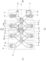
- FIG. 3 is a schematic view showing a schematic configuration of the upper surface of the first hand in the robot shown in FIG.
- FIG. 4 is a schematic view showing a schematic configuration of the back surface of the first hand in the robot shown in FIG.
- FIG. 5 is a schematic diagram showing a schematic configuration of a main part of the first hand in the robot shown in FIG.
- FIG. 6A is a flowchart showing an example of the operation of the robot system according to the first embodiment.
- FIG. 6B is a flowchart showing an example of the operation of the robot system according to the first embodiment.
- FIG. 6A is a flowchart showing an example of the operation of the robot system according to the first embodiment.
- FIG. 6B is a flowchart showing an example of the operation of the robot system according to the first embodiment.
- FIG. 7 is a schematic view showing a state of the robot when the robot system is operating according to the flowcharts shown in FIGS. 6A and 6B.
- FIG. 8 is a flowchart showing an example of the operation of the robot system according to the first embodiment.
- FIG. 9 is a schematic view showing a state of the robot when the robot system is operating according to the flowcharts shown in FIGS. 6A and 6B.
- FIG. 10 is a schematic view showing a state of the robot when the robot system is operating according to the flowcharts shown in FIGS. 6A and 6B.
- FIG. 11 is a schematic view showing a state of the robot when the robot system is operating according to the flowcharts shown in FIGS. 6A and 6B.
- FIG. 12 is a schematic diagram showing a schematic configuration of the robot system according to the second embodiment.
- the robot system according to the first embodiment has a plurality of first holding portions, a first link mechanism configured to change the interval between the plurality of first holding portions, and an engaging portion.
- a second hand having a first hand, a plurality of second holding portions, a second link mechanism configured to vary the distance between the plurality of second holding portions, and an engaged portion.
- a first arm to which the first hand is connected, a second arm to which the second hand is connected, and a control device are provided, and the control device is provided so that the engaged portion engages with the engaged portion.
- the first arm and / or the second arm is operated, and after (A), the first arm is operated so as to change the interval between the plurality of first holding portions (B). Is configured to run.
- control device further executes (C) to operate the second arm so as to change the interval between the plurality of second holding portions. It may be configured as follows.
- the first hand further has an engaged portion
- the second hand further has an engaged portion
- the control device has the first in (A).
- the first arm and / or the first arm so that the engaging portion of the first hand engages with the engaged portion of the second hand and the engaging portion of the second hand engages with the engaged portion of the first hand. It may be configured to operate the two arms.
- FIG. 1 is a schematic diagram showing a schematic configuration of a robot system according to the first embodiment.
- FIG. 2 is a functional block diagram schematically showing the configuration of the robot control device shown in FIG.
- a horizontal articulated dual-arm robot will be described as a robot constituting the robot system according to the first embodiment, but the robot is not limited thereto.
- the robot constituting the robot system according to the first embodiment other robots such as a horizontal articulated type and a vertical articulated type may be adopted.
- the robot system 100 controls the carriage 12, the first arm 13A, the second arm 13B, and the vacuum generator 25 arranged in the carriage 12.
- a robot 101 having a device 110 and a device 110 is provided. Further, a control device 110 is arranged in the carriage 12.
- control device 110 and the vacuum generator 25 are arranged inside the carriage 12, but the present invention is not limited to this, and these devices are arranged outside the carriage 12. It may have been done.
- the vacuum generator 25 is connected to the suction portion 8 of the first arm 13A and the second arm 13B, which will be described later, by the pipe 93A and the pipe 93B.
- the vacuum generator 25 is a device that creates a negative pressure in the suction unit 8, and for example, a vacuum pump, CONVUM (registered trademark), or the like may be used.
- the on-off valve 94A and the on-off valve 94B are provided in the pipe 93A and the pipe 93B, respectively.
- the on-off valve 94A and the on-off valve 94B open or close the pipe 93A and the pipe 93B, respectively, so that the suction portion (first holding portion or the second holding portion) 8 can attract (hold) the work 103 and release the work 103. Will be done.
- the operation of the vacuum generator 25 and the opening / closing operation of the on-off valve 94A and the on-off valve 94B are controlled by the control device 110.
- the base shaft 16 is fixed to the upper surface of the dolly 12.
- the base shaft 16 is provided with a first arm 13A and a second arm 13B so as to be rotatable around a rotation axis L1 passing through the axis of the base shaft 16.
- the first arm 13A and the second arm 13B are provided so as to have a height difference in the vertical direction.
- the first arm 13A and the second arm 13B are configured to be able to operate independently or in relation to each other.
- the first arm 13A has a first arm portion 15A, a first wrist portion 17A, a first hand 18A, and a first mounting portion 20A.
- the second arm 13B has a second arm portion 15B, a second wrist portion 17B, a second hand 18B, and a second mounting portion 20B. Since the basic configuration of the second arm 13B is the same as that of the first arm 13A, detailed description thereof will be omitted.
- the first arm portion 15A is composed of a substantially rectangular parallelepiped first link 5a and a second link 5b.
- the first link 5a is provided with a rotary joint J1 at the base end portion and a rotary joint J2 at the tip end portion.
- the second link 5b is provided with a linear motion joint J3 at the tip end portion.
- the base end of the first link 5a is connected to the base shaft 16 via the rotary joint J1, and the first link 5a can be rotated around the rotary axis L1 by the rotary joint J1. Further, the base end portion of the second link 5b is connected to the tip end portion of the first link 5a via the rotary joint J2, and the second link 5b can be rotated around the rotation axis L2 by the rotary joint J2.
- the first wrist portion 17A is connected to the tip of the second link 5b via a linear motion joint J3 so as to be vertically movable with respect to the second link 5b.
- a rotary joint J4 is provided at the lower end of the first wrist portion 17A, and a first mounting portion 20A is provided at the lower end of the rotary joint J4.
- the first mounting portion 20A is configured so that the first hand 18A can be attached and detached.
- the first mounting portion 20A has a pair of rod members whose intervals are adjustable, and the first hand 18A is sandwiched between the pair of rod members.
- the first hand 18A can be attached to the first wrist unit 17A.
- the first hand 18A can be rotated around the rotation axis L3 by the rotation joint J4.
- the tip of the rod member may be bent.
- the structure of the first hand 18A will be described later.
- each of the joints J1 to J4 of the first arm 13A and the second arm 13B is provided with a drive motor as an example of an actuator that relatively rotates or raises and lowers two members to which the joints are connected.
- the drive motor may be, for example, a servomotor that is servo-controlled by the control device 110.
- each of the joints J1 to J4 has a rotation sensor (not shown) that detects the rotation position of the drive motor, and a current sensor (not shown) that detects the current that controls the rotation of the drive motor. Is provided.
- the rotation sensor may be, for example, an encoder.
- the control device 110 includes an arithmetic processor 110a, a storage device 110b, and an input device 110c.
- the arithmetic processor 110a is composed of a microprocessor, a CPU, and the like, and controls various operations of the robot system 100 by reading and executing software such as a basic program stored in the storage device 110b.
- the storage device 110b stores information such as a basic program and various fixed data.
- the storage device 110b does not have to be a single device, and may be configured as a plurality of storage devices (for example, a random access memory and a hard disk drive).
- the arithmetic processing unit 110a is composed of a microcomputer, at least a part of the storage device 110b may be configured as an internal memory of the microcomputer or may be configured as an independent memory.
- the input device 110c is capable of inputting various parameters related to the control of the robot system 100, other data, and the like to the arithmetic processing device 110a, and is a known input device such as a keyboard, a touch panel, and a button switch group. It is configured.
- data such as the holding condition of the work 103 (weight of the work 103, etc.), the number of works 103 to be stored in the container, and the like may be input by the input device 110c.
- the control device 110 may be composed of a single control device 110 for centralized control, or may be composed of a plurality of control devices 110 for distributed control in cooperation with each other. Further, the control device 110 may be composed of a microcomputer, an MPU, a PLC (Programmable Logic Controller), a logic circuit, or the like.
- a microcomputer an MPU, a PLC (Programmable Logic Controller), a logic circuit, or the like.
- the first hand 18A of the first arm 13A will be described in detail with reference to FIGS. 3 to 5. Since the second hand 18B of the second arm 13B has the same basic configuration as the first hand 18A, detailed description thereof will be omitted.
- FIG. 3 is a schematic view showing a schematic configuration of the upper surface of the first hand in the robot shown in FIG.
- FIG. 4 is a schematic view showing a schematic configuration of the back surface of the first hand in the robot shown in FIG.
- FIG. 5 is a schematic diagram showing a schematic configuration of a main part of the first hand in the robot shown in FIG.
- FIGS. 3 to 5 the front-back direction, the left-right direction, and the up-down direction of the robot (first hand) are represented as the front-back direction, the left-right direction, and the up-down direction in the figure, respectively. Further, in FIGS. 3 and 5, the description of the work is omitted.
- the first hand 18A of the first arm 13A has a main body 81, a base member 82, a link mechanism (first link mechanism) 83, and a plurality of suction portions 8A to 8H.
- the adsorption units 8A to 8H are not distinguished, they may be referred to as the adsorption unit 8.
- the main body 81 is composed of a housing, and a base member 82 is provided at the lower end portion thereof.
- the base member 82 is formed in a substantially T shape when viewed from the vertical direction.
- a link mechanism 83 configured to be able to advance and retreat in the left-right direction is arranged below the base member 82.
- the first mechanism 84 is provided at the right end of the upper end surface of the base member 82.
- the first mechanism 84 has a drum 84A and a tape 84B.
- the drum 84A is equipped with a mainspring (winding spring; not shown).
- the base end portion of the tape 84B is connected to the mainspring, and the tip end portion of the tape 84B is fixed to the first fixing member 71.
- the first fixing member 71 is connected to the link mechanism 83 via the first guide member 31 of the linear guide 30, which will be described later. As a result, the extended link mechanism 83 can be retracted by the spring force of the mainspring.
- a first stopper 41 is provided at a substantially central portion of the upper end surface of the base member 82.
- the first stopper 41 has a substantially L-shaped second fixing member 42 and a linear actuator 43.
- the linear actuator 43 has a cylinder, a piston, and a drive mechanism for moving the piston forward and backward.
- the tip surface of the linear actuator 43 comes into contact with the main surface of the tape 84B and presses the tape 84B on the tip surface of the linear actuator 43 and the main surface of the second fixing member 42. It is configured to be sandwiched.
- the link mechanism 83 can be set to an arbitrary length (maintained at an arbitrary length), and the distance between the suction portions 8 and 8 adjacent to each other in the left-right direction can be set to an arbitrary length. ..
- the linear actuator 43 may be configured such that the frictional force generated by sandwiching the tape 84B is larger than the spring force of the mainspring, a small motor can be used as the drive mechanism. it can. Therefore, it is possible to suppress an increase in the weight of the first hand 18A, and it is possible to hold and transport a work having a heavier weight than the conventional robot system.
- a third fixing member 73 and a linear guide 30 are provided on the lower end surface of the base member 82.
- the tip of the first shaft member 831 of the link mechanism 83, which will be described later, is fitted to the third fixing member 73.
- the linear guide 30 has a first guide member 31, a second guide member 32, and a rail member 33.
- the rail member 33 is formed so as to extend in the left-right direction, and is configured to guide the first guide member 31 and the second guide member 32.
- a second stopper 52 is provided on the front surface of the first guide member 31 and the second guide member 32.
- the second stopper 52 has a rod-shaped first member 52A and a box-shaped second member 52B, and the tip of the first member 52A comes into contact with the second member 52B to stop the tape 84B from regressing. It is configured to do. Further, the length of the first member 52A is set in advance so that the adjacent suction portions 8 and 8 do not come into contact with each other.
- the tip of the second shaft member 832 of the link mechanism 83 which will be described later, is fitted to the first guide member 31, and the tip of the third shaft member 833 of the link mechanism 83 is fitted to the second guide member 32. The parts are fitted.
- the link mechanism 83 employs a pantograph mechanism and has strip-shaped link members 83A to 83F and first shaft members 831 to third shaft members 833.
- a rail mechanism may be adopted, and a configuration in which the distance between the two suction portions 8 and 8 may be changed may be adopted.
- the link member 83A and the link member 83B are arranged in an X shape when viewed from the vertical direction, and the first shaft member 831 is inserted at the intersection of the link member 83A and the link member 83B.
- the link member 83C and the link member 83D are also arranged in an X shape when viewed from the vertical direction, and the second shaft member 832 is inserted at the intersection of the link member 83C and the link member 83D. ..
- the link member 83E and the link member 83F are also arranged in an X shape when viewed from the vertical direction, and a third shaft member 833 is inserted at the intersection of the link member 83E and the link member 83F.
- Each of the link member 83A to the link member 83D is bent at the right end portion, and the suction portion 8 is provided at the right end portion (base end). Further, the link member 83E and the link member 83F are bent at both the right end portion and the left end portion, respectively, and the suction portion 8 is provided at the right end end (base end), respectively. Further, a truncated cone-shaped suction pad 80 is provided at the tip end portion (lower end portion) of the suction portion 8.
- the tip of the link member 83A is rotatably connected to the bent portion of the link member 83D by the shaft member 830A.
- the tip end portion of the link member 83B is rotatably connected to the bent portion of the link member 83C by the shaft member 830B.
- the tip of the link member 83C is rotatably connected to the right bent portion of the link member 83F by the shaft member 830C.
- the tip end portion of the link member 83D is rotatably connected to the right bending portion of the link member 83E by the shaft member 830D.
- An L-shaped first connecting member 91 is provided at the left bending portion of the link member 83F.
- a pin-shaped first engaging portion (engaging portion) 91A is provided at the tip of the first connecting member 91.
- an L-shaped second connecting member 92 is provided at the left bending portion of the link member 83E.
- a hole is formed in the main surface of the second connecting member 92, and the hole constitutes the first engaged portion (engaged portion) 91B.
- a second engaging portion (engaging portion) 92A is provided in place of the first engaging portion 91A, and the first engaged portion is provided.
- a second engaged portion (engaged portion) 92B is provided.
- the link mechanism (first link mechanism) 83 of the first hand 18A constitutes the second link mechanism.
- a form in which the work 103 is sucked and held by the suction portion 8 is adopted, but the present invention is not limited to this.
- a form in which the work 103 is gripped by a pair of claws or the like arranged in the front-rear direction may be adopted.
- the suction portions 8A to 8D (8E to 8H) are arranged so as to be arranged in the left-right direction. Is adopted. Therefore, when a plurality of works 103 are arranged so as to be arranged in the front-rear direction, a configuration is adopted in which the suction portions 8A to 8D (8E to 8H) are arranged so as to be arranged in the front-rear direction.
- the first hand 18A has the first engaging portion 91A and the first engaged portion 91B
- the second hand 18B has the second engaging portion 92A
- a form having the second engaged portion 92B is adopted, but the present invention is not limited to this.
- a form in which the first hand 18A has the first engaging portion 91A and the second hand 18B has the second engaged portion 92B may be adopted.
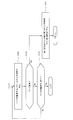
- FIGS. 6A and 6B are flowcharts showing an example of the operation of the robot system according to the first embodiment.
- 7 to 11 are schematic views showing a state of the robot when the robot system is operating according to the flowcharts shown in FIGS. 6A and 6B.
- the first hand 18A and the second hand 18B are in the initial state in which the first member 52A is in contact with the second member 52B.
- the first stopper 41 is operating when the first hand 18A and the second hand 18B are in the initial state. That is, it is assumed that the tape 84B is sandwiched between the tip of the linear actuator 43 of the first stopper 41 and the second fixing member 42.
- control device 110 instruction information indicating that the operation of holding and transporting the work 103 indicated by the alternate long and short dash line is executed via the input device 110c.
- control device 110 executes the following operations.
- the first engaging portion 91A of the first hand 18A and the second engaged portion 92B of the second hand 18B are engaged with each other, and the second engaging portion 92A of the second hand 18B and the second engaged portion 92B are engaged.
- the first arm 13A and / or the second arm 13B is operated so that the first engaged portion 91B of the one hand 18A is engaged (step S101).
- the control device 110 operates the first arm 13A and / or the second arm 13B so that the first hand 18A and the second hand 18B are close to each other.
- the pin-shaped first engaging portion 91A and the second engaging portion 92A are inserted into the holes forming the second engaged portion 92B and the first engaged portion 91B, respectively.
- the first arm 13A and / or the second arm 13B is operated.
- control device 110 releases the first stopper 41 of the first hand 18A (step S102). Specifically, the control device 110 drives the linear actuator 43 so that the tip of the piston of the first stopper 41 retracts, and separates the tip of the piston from the tape 84B.
- control device 110 operates the first arm 13A so as to change the interval between the adjacent suction units 8 and 8 (step S103). That is, in the robot system 100 according to the first embodiment, as an actuator, the first arm 13A holding the first hand 18A changes the interval between the adjacent suction portions 8 and 8 of the first hand 18A. It is functioning.
- control device 110 operates the first stopper 41 of the first hand 18A when the distance between the suction portions 8 and 8 becomes a length that can correspond to the size of the work 103 (step S104). ..
- the interval between the suction portions 8 and 8, which can correspond to the size of the work 103, is set in advance by an experiment or the like, and the interval is stored in the storage device 110b.
- control device 110 releases the first stopper 41 of the second hand 18B (step S105).
- control device 110 operates the second arm 13B so as to change the interval between the adjacent suction units 8 and 8 (step S106).
- the control device 110 operates the first stopper 41 of the second hand 18B when the distance between the suction portions 8 and 8 becomes a length that can correspond to the size of the work 103 (step S107).
- control device 110 engages with the first engaging portion 91A of the first hand 18A and the second engaged portion 92B of the second hand 18B, and with the second engaging portion 92A of the second hand 18B.
- the first arm 13A and / or the second arm 13B is operated so as to disengage the first hand 18A from the first engaged portion 91B (step S108).
- control device 110 operates the robot 101 (first arm 13A and second arm 13B) so as to convey the work 103 (step S109).
- control device 110 operates the first arm 13A and the second arm 13B so that the first hand 18A and the second hand 18B are located above the work 103.
- control device 110 operates the vacuum generator 25 to open the valve bodies of the on-off valve 94A and the on-off valve 94B.
- control device 110 operates the first arm 13A and the second arm 13B so that the suction unit 8 comes into contact with the work 103. As a result, the suction unit 8 can suck and hold the work 103.
- control device 110 operates the first arm 13A and the second arm 13B to convey the work 103 to a predetermined position set in advance. Then, the control device 110 closes the valve bodies of the on-off valve 94A and the on-off valve 94B, and releases the work 103.
- control device 110 determines whether or not a command for changing the type, size, weight, etc. of the work 103 being conveyed from the input device 110c has been input (step S110). At this time, the control device 110 determines whether or not a command for transporting a work having a width larger than that of the work 103 shown in FIG. 7 has been input from the input device 110c, such as the work 103A shown in FIG. judge.
- step S110 When the control device 110 determines that a command for changing the type of the work 103 being conveyed from the input device 110c has been input (Yes in step S110), the first hand 18A and the second hand 18B are the first. The stopper 41 is released, the first hand 18A and the second hand 18B are returned to the initial state (step S111), and the process returns to the process of step S101.
- control device 110 determines that the command for changing the type or the like of the work 103 being conveyed from the input device 110c has not been input (No in step S110), has the transfer of the work 103 been completed? It is determined whether or not (step S112).
- control device 110 determines that the transfer of the work 103 has not been completed (No in step S112), the control device 110 repeats the processes of steps S109 to S112 until it determines that the transfer of the work 103 has been completed.
- control device 110 determines that the transfer of the work 103 is completed (Yes in step S112), the control device 110 ends this program.
- the intervals of the suction portions 8 are changed between the first hand 18A and the second hand 18B. Since no actuator is provided for this purpose, it is possible to hold and transport a work that is heavier than that of a conventional robot system.
- the linear actuator 43 provided in the first hand 18A and the second hand 18B has a frictional force generated by sandwiching the tape 84B as a spring of the mainspring. It is configured to be greater than the force.
- a small motor can be used as the drive mechanism of the linear actuator 43.
- the second stopper 52 is provided on the first hand 18A and the second hand 18B. As a result, when the first stopper 41 is released, the contact between the adjacent suction portions 8 and 8 can be suppressed.
- the robot system according to the second embodiment includes a first robot having a first arm and a second robot having a second arm in the robot system according to the first embodiment.
- FIG. 12 is a schematic diagram showing a schematic configuration of the robot system according to the second embodiment.
- the robot system 100 includes two robots 101A and 101B.
- the robot 101A has a first arm 13A to which the first hand 18A is connected, and the robot 101B has a second arm 13B to which the second hand 18B is connected.
- the robots 101A and 101B employ a known vertical articulated robot in the second embodiment, detailed description thereof will be omitted. Further, in the second embodiment, the vertical articulated robot is adopted, but the present invention is not limited to this, and other robots such as the horizontal articulated robot may be adopted.
- the mode in which the robots 101A and 101B are controlled by one control device 110 is adopted, but the present invention is not limited to this, and the robots 101A and 101B are controlled by a plurality of control devices 110. You may adopt the form of.
- the robot system and its operation method according to the present invention are useful in the field of industrial robots because they can hold and transport heavier workpieces than conventional robot systems.
Landscapes
- Engineering & Computer Science (AREA)
- Mechanical Engineering (AREA)
- Robotics (AREA)
- Manipulator (AREA)
Abstract
A robot system according to the present invention is provided with: a first hand (18A) that has a plurality of first holding units (8), a first link mechanism (83), and a first engagement unit (91A); a second hand (18B) that has a plurality of second holding units (8), a second link mechanism (83), and a second engaged unit (92B); a first arm (13A) to which the first hand (18A) is connected; a second arm (13B) to which the second hand (18B) is connected; and a control device (110) which is configured to execute (A) to operate the first arm (13A) and/or the second arm (13B) so that the first engagement unit (91A) is engaged with the second engaged unit (92B) and execute, after executing (A), (B) to operate the first arm (13A) so that a gap between the plurality of the first holding units (8) is varied.
Description
本発明は、ロボットシステム及びその運転方法に関する。
The present invention relates to a robot system and its operation method.
同時に複数の部品を精度良く位置決めすることを目的とした、ロボット装置が知られている(例えば、特許文献1参照)。
A robot device is known for the purpose of accurately positioning a plurality of parts at the same time (see, for example, Patent Document 1).
特許文献1に開示されているロボット装置は、回転駆動源(サーボモータ)によって、軸を中心に回転するピニオンと、一対のラックによって開閉されるリンク機構(パンタグラフ機構)と、リンク機構に支持された複数の保持部と、を有する部品位置決め装置がロボットアームの先端に設けられている。そして、リンク機構の開閉動作に応じて、隣り合う保持部同士の間隔が変化することで、保持部の位置決めを行っている。
The robot device disclosed in Patent Document 1 is supported by a pinion that rotates about an axis by a rotary drive source (servomotor), a link mechanism (pantograph mechanism) that is opened and closed by a pair of racks, and a link mechanism. A component positioning device having a plurality of holding portions is provided at the tip of the robot arm. Then, the holding portions are positioned by changing the distance between the adjacent holding portions according to the opening / closing operation of the link mechanism.
しかしながら、特許文献1に開示されているロボット装置では、保持部の間隔を変動するために、回転駆動源、ピニオン、及び一対のラックを設けている。このため、ロボットアームの先端の重量が大きくなり、その結果、重量の大きなワークを保持して、搬送することができないという課題があった。
However, in the robot device disclosed in Patent Document 1, a rotary drive source, a pinion, and a pair of racks are provided in order to change the distance between the holding portions. Therefore, the weight of the tip of the robot arm becomes large, and as a result, there is a problem that a heavy work cannot be held and conveyed.
本発明は、上記従来の課題を解決するもので、従来のロボットシステムに比して、重量の大きいワークを保持し、搬送することができる、ロボットシステム及びその運転方法を提供することを目的としている。
The present invention solves the above-mentioned conventional problems, and an object of the present invention is to provide a robot system and an operation method thereof capable of holding and transporting a work heavier than a conventional robot system. There is.
上記従来の課題を解決するために、本発明に係るロボットシステムは、複数の第1保持部と、当該複数の第1保持部の間隔を変動させるように構成されている第1リンク機構と、第1係合部と、を有する第1ハンドと、複数の第2保持部と、当該複数の第2保持部の間隔を変動させるように構成されている第2リンク機構と、第2被係合部と、を有する第2ハンドと、前記第1ハンドが接続されている第1アームと、前記第2ハンドが接続されている第2アームと、制御装置と、を備え、前記制御装置は、前記係合部が前記被係合部と係合するように、前記第1アーム及び/又は前記第2アームを動作させる(A)と、前記(A)の後に、複数の第1保持部の間隔を変動させるように、前記第1アームを動作させる(B)と、を実行するように構成されている。
In order to solve the above-mentioned conventional problems, the robot system according to the present invention includes a plurality of first holding portions, a first link mechanism configured to change the interval between the plurality of first holding portions, and a first link mechanism. A first hand having a first engaging portion, a plurality of second holding portions, a second link mechanism configured to vary the distance between the plurality of second holding portions, and a second engaged portion. The control device includes a second hand having a joint portion, a first arm to which the first hand is connected, a second arm to which the second hand is connected, and a control device. When the first arm and / or the second arm is operated so that the engaging portion engages with the engaged portion (A), after the (A), a plurality of first holding portions (B), in which the first arm is operated so as to fluctuate the interval between the above, is configured to be executed.
これにより、第1ハンド及び第2ハンドに、第1保持部及び第2保持部の間隔を変更するためのアクチュエータを設けることなく、第1保持部及び第2保持部の間隔を変更することができる。また、第1保持部及び第2保持部の間隔を変更するためのアクチュエータを設けていないので、従来のロボットシステムに比して、重量の大きいワークを保持し、搬送することができる。
As a result, the distance between the first holding part and the second holding part can be changed without providing an actuator for changing the distance between the first holding part and the second holding part in the first hand and the second hand. it can. Further, since the actuator for changing the distance between the first holding portion and the second holding portion is not provided, it is possible to hold and convey a work having a heavier weight as compared with the conventional robot system.
また、本発明に係るロボットシステムの運転方法は、前記ロボットシステムは、複数の第1保持部と、当該複数の第1保持部の間隔を変動させるように構成されている第1リンク機構と、係合部と、を有する第1ハンドと、複数の第2保持部と、当該複数の第2保持部の間隔を変動させるように構成されている第2リンク機構と、被係合部と、を有する第2ハンドと、前記第1ハンドが接続されている第1アームと、前記第2ハンドが接続されている第2アームと、を備え、前記係合部が前記被係合部と係合するように、前記第1アーム及び/又は前記第2アームが動作する(A)と、前記(A)の後に、複数の第1保持部の間隔を変動させるように、前記第1アームが動作する(B)と、備える。
Further, in the operation method of the robot system according to the present invention, the robot system includes a plurality of first holding portions and a first link mechanism configured to change the interval between the plurality of first holding portions. A first hand having an engaging portion, a plurality of second holding portions, a second link mechanism configured to vary the distance between the plurality of second holding portions, an engaged portion, and the like. A second hand having the above, a first arm to which the first hand is connected, and a second arm to which the second hand is connected are provided, and the engaging portion engages with the engaged portion. When the first arm and / or the second arm operates so as to match (A), after the (A), the first arm changes the interval between the plurality of first holding portions. Be prepared to operate (B).
これにより、第1ハンド及び第2ハンドに、第1保持部及び第2保持部の間隔を変更するためのアクチュエータを設けることなく、第1保持部及び第2保持部の間隔を変更することができる。また、第1保持部及び第2保持部の間隔を変更するためのアクチュエータを設けていないので、従来のロボットシステムに比して、重量の大きいワークを保持し、搬送することができる。
As a result, the distance between the first holding part and the second holding part can be changed without providing an actuator for changing the distance between the first holding part and the second holding part in the first hand and the second hand. it can. Further, since the actuator for changing the distance between the first holding portion and the second holding portion is not provided, it is possible to hold and convey a work having a heavier weight as compared with the conventional robot system.
本発明の上記目的、他の目的、特徴、及び利点は、添付図面参照の下、以下の好適な実施形態の詳細な説明から明らかにされる。
The above objectives, other objectives, features, and advantages of the present invention will be clarified from the following detailed description of preferred embodiments with reference to the accompanying drawings.
本発明のロボットシステム及びその運転方法によれば、第1ハンド及び第2ハンドには、第1保持部及び第2保持部の間隔を変更するためのアクチュエータを設けていないので、従来のロボットシステムに比して、重量の大きいワークを保持し、搬送することができる。
According to the robot system of the present invention and its operation method, the first hand and the second hand are not provided with an actuator for changing the distance between the first holding portion and the second holding portion, and thus the conventional robot system. It is possible to hold and transport a work having a large weight as compared with the above.
以下、本発明の実施の形態を、図面を参照しながら説明する。なお、全ての図面において、同一又は相当部分には同一符号を付し、重複する説明は省略する。また、全ての図面において、本発明を説明するための構成要素を抜粋して図示しており、その他の構成要素については図示を省略している場合がある。さらに、本発明は以下の実施の形態に限定されない。
Hereinafter, embodiments of the present invention will be described with reference to the drawings. In all drawings, the same or corresponding parts are designated by the same reference numerals, and duplicate description will be omitted. Further, in all the drawings, the components for explaining the present invention are excerpted and shown, and the other components may be omitted. Furthermore, the present invention is not limited to the following embodiments.
(実施の形態1)
本実施の形態1に係るロボットシステムは、複数の第1保持部と、当該複数の第1保持部の間隔を変動させるように構成されている第1リンク機構と、係合部と、を有する第1ハンドと、複数の第2保持部と、当該複数の第2保持部の間隔を変動させるように構成されている第2リンク機構と、被係合部と、を有する第2ハンドと、第1ハンドが接続されている第1アームと、第2ハンドが接続されている第2アームと、制御装置と、を備え、制御装置は、係合部が被係合部と係合するように、第1アーム及び/又は第2アームを動作させる(A)と、(A)の後に、複数の第1保持部の間隔を変動させるように、第1アームを動作させる(B)と、を実行するように構成されている。 (Embodiment 1)
The robot system according to the first embodiment has a plurality of first holding portions, a first link mechanism configured to change the interval between the plurality of first holding portions, and an engaging portion. A second hand having a first hand, a plurality of second holding portions, a second link mechanism configured to vary the distance between the plurality of second holding portions, and an engaged portion. A first arm to which the first hand is connected, a second arm to which the second hand is connected, and a control device are provided, and the control device is provided so that the engaged portion engages with the engaged portion. In (A), the first arm and / or the second arm is operated, and after (A), the first arm is operated so as to change the interval between the plurality of first holding portions (B). Is configured to run.
また、本実施の形態1に係るロボットシステムでは、制御装置は、(B)の後に、複数の第2保持部の間隔を変動させるように、第2アームを動作させる(C)をさらに実行するように構成されていてもよい。
Further, in the robot system according to the first embodiment, after (B), the control device further executes (C) to operate the second arm so as to change the interval between the plurality of second holding portions. It may be configured as follows.
さらに、本実施の形態1に係るロボットシステムでは、第1ハンドは、被係合部をさらに有し、第2ハンドは、係合部をさらに有し、制御装置は、(A)において、第1ハンドの係合部が第2ハンドの被係合部と係合し、第2ハンドの係合部が第1ハンドの被係合部と係合するように、第1アーム及び/又は第2アームを動作させるように構成されていてもよい。
Further, in the robot system according to the first embodiment, the first hand further has an engaged portion, the second hand further has an engaged portion, and the control device has the first in (A). The first arm and / or the first arm so that the engaging portion of the first hand engages with the engaged portion of the second hand and the engaging portion of the second hand engages with the engaged portion of the first hand. It may be configured to operate the two arms.
以下、本実施の形態1に係るロボットシステムの一例について、図1~図11を参照しながら説明する。
Hereinafter, an example of the robot system according to the first embodiment will be described with reference to FIGS. 1 to 11.
[ロボットシステムの構成]
図1は、本実施の形態1に係るロボットシステムの概略構成を示す模式図である。図2は、図1に示すロボットの制御装置の構成を概略的に示す機能ブロック図である。 [Robot system configuration]
FIG. 1 is a schematic diagram showing a schematic configuration of a robot system according to the first embodiment. FIG. 2 is a functional block diagram schematically showing the configuration of the robot control device shown in FIG.
なお、図1においては、ロボットにおける上下方向及び左右方向を図における上下方向及び左右方向として表している。
Note that in FIG. 1, the vertical direction and the horizontal direction of the robot are represented as the vertical direction and the horizontal direction in the figure.
また、以下においては、本実施の形態1に係るロボットシステムを構成するロボットとして、水平多関節型の双腕ロボットについて、説明するが、これに限定されない。本実施の形態1に係るロボットシステムを構成するロボットとして、水平多関節型・垂直多関節型等の他のロボットを採用してもよい。
Further, in the following, a horizontal articulated dual-arm robot will be described as a robot constituting the robot system according to the first embodiment, but the robot is not limited thereto. As the robot constituting the robot system according to the first embodiment, other robots such as a horizontal articulated type and a vertical articulated type may be adopted.
図1に示すように、本実施の形態1に係るロボットシステム100は、台車12と、第1アーム13Aと、第2アーム13Bと、台車12内に配置されている真空発生装置25と、制御装置110と、を有するロボット101を備えている。また、台車12内には、制御装置110が配置されている。
As shown in FIG. 1, the robot system 100 according to the first embodiment controls the carriage 12, the first arm 13A, the second arm 13B, and the vacuum generator 25 arranged in the carriage 12. A robot 101 having a device 110 and a device 110 is provided. Further, a control device 110 is arranged in the carriage 12.
なお、本実施の形態1においては、台車12の内部に制御装置110及び真空発生装置25が配置されている形態を採用したが、これに限定されず、これらの機器は、台車12外部に配置されていてもよい。
In the first embodiment, the control device 110 and the vacuum generator 25 are arranged inside the carriage 12, but the present invention is not limited to this, and these devices are arranged outside the carriage 12. It may have been done.
真空発生装置25は、配管93A及び配管93Bにより、後述する第1アーム13A及び第2アーム13Bの吸着部8と接続されている。真空発生装置25は、吸着部8内を負圧にする装置であり、例えば、真空ポンプ又はCONVUM(登録商標)等を用いてもよい。
The vacuum generator 25 is connected to the suction portion 8 of the first arm 13A and the second arm 13B, which will be described later, by the pipe 93A and the pipe 93B. The vacuum generator 25 is a device that creates a negative pressure in the suction unit 8, and for example, a vacuum pump, CONVUM (registered trademark), or the like may be used.
また、配管93A及び配管93Bには、それぞれ、開閉弁94A及び開閉弁94Bが設けられている。開閉弁94A及び開閉弁94Bが、それぞれ、配管93A及び配管93Bを開放又は閉鎖することによって、吸着部(第1保持部又は第2保持部)8によるワーク103の吸着(保持)及びその解除が行われる。なお、真空発生装置25の動作と、開閉弁94A及び開閉弁94Bの開閉動作は、制御装置110により制御される。
Further, the on-off valve 94A and the on-off valve 94B are provided in the pipe 93A and the pipe 93B, respectively. The on-off valve 94A and the on-off valve 94B open or close the pipe 93A and the pipe 93B, respectively, so that the suction portion (first holding portion or the second holding portion) 8 can attract (hold) the work 103 and release the work 103. Will be done. The operation of the vacuum generator 25 and the opening / closing operation of the on-off valve 94A and the on-off valve 94B are controlled by the control device 110.
台車12の上面には、基軸16が固定されている。基軸16には、当該基軸16の軸心を通る回転軸線L1回りに回動可能に第1アーム13A及び第2アーム13Bが設けられている。具体的には、第1アーム13Aと第2アーム13Bとが上下に高低差を有するように設けられている。なお、第1アーム13A及び第2アーム13Bは、独立して動作したり、互いに関連して動作したりすることができるように構成されている。
The base shaft 16 is fixed to the upper surface of the dolly 12. The base shaft 16 is provided with a first arm 13A and a second arm 13B so as to be rotatable around a rotation axis L1 passing through the axis of the base shaft 16. Specifically, the first arm 13A and the second arm 13B are provided so as to have a height difference in the vertical direction. The first arm 13A and the second arm 13B are configured to be able to operate independently or in relation to each other.
第1アーム13Aは、第1アーム部15A、第1リスト部17A、第1ハンド18A、及び第1装着部20Aを有している。同様に、第2アーム13Bは、第2アーム部15B、第2リスト部17B、第2ハンド18B、及び第2装着部20Bを有している。なお、第2アーム13Bは、基本的な構成は、第1アーム13Aと同様に構成されているため、その詳細な説明は省略する。
The first arm 13A has a first arm portion 15A, a first wrist portion 17A, a first hand 18A, and a first mounting portion 20A. Similarly, the second arm 13B has a second arm portion 15B, a second wrist portion 17B, a second hand 18B, and a second mounting portion 20B. Since the basic configuration of the second arm 13B is the same as that of the first arm 13A, detailed description thereof will be omitted.
第1アーム部15Aは、本実施の形態1においては、略直方体状の第1リンク5a及び第2リンク5bで構成されている。第1リンク5aは、基端部に回転関節J1が設けられていて、先端部に回転関節J2が設けられている。また、第2リンク5bは、先端部に直動関節J3が設けられている。
In the first embodiment, the first arm portion 15A is composed of a substantially rectangular parallelepiped first link 5a and a second link 5b. The first link 5a is provided with a rotary joint J1 at the base end portion and a rotary joint J2 at the tip end portion. Further, the second link 5b is provided with a linear motion joint J3 at the tip end portion.
そして、第1リンク5aは、回転関節J1を介して、その基端部が基軸16と連結されていて、回転関節J1により、回転軸線L1回りに回動することができる。また、第2リンク5bは、回転関節J2を介して、その基端部が第1リンク5aの先端部と連結されていて、回転関節J2により、回転軸線L2回りに回動することができる。
The base end of the first link 5a is connected to the base shaft 16 via the rotary joint J1, and the first link 5a can be rotated around the rotary axis L1 by the rotary joint J1. Further, the base end portion of the second link 5b is connected to the tip end portion of the first link 5a via the rotary joint J2, and the second link 5b can be rotated around the rotation axis L2 by the rotary joint J2.
第2リンク5bの先端部には、直動関節J3を介して、第1リスト部17Aが第2リンク5bに対し昇降移動可能に連結されている。第1リスト部17Aの下端部には、回転関節J4が設けられていて、回転関節J4の下端部には、第1装着部20Aが設けられている。
The first wrist portion 17A is connected to the tip of the second link 5b via a linear motion joint J3 so as to be vertically movable with respect to the second link 5b. A rotary joint J4 is provided at the lower end of the first wrist portion 17A, and a first mounting portion 20A is provided at the lower end of the rotary joint J4.
第1装着部20Aは、第1ハンド18Aを着脱可能に構成されている。具体的には、例えば、第1装着部20Aは、その間隔が調整可能に構成されている、一対の棒部材を有していて、当該一対の棒部材により、第1ハンド18Aを挟み込むことにより、第1ハンド18Aを第1リスト部17Aに装着することができる。これにより、第1ハンド18Aは、回転関節J4により、回転軸線L3回りに回動することができる。なお、棒部材は先端部分が折れ曲がっていてもよい。また、第1ハンド18Aの構造については、後述する。
The first mounting portion 20A is configured so that the first hand 18A can be attached and detached. Specifically, for example, the first mounting portion 20A has a pair of rod members whose intervals are adjustable, and the first hand 18A is sandwiched between the pair of rod members. , The first hand 18A can be attached to the first wrist unit 17A. As a result, the first hand 18A can be rotated around the rotation axis L3 by the rotation joint J4. The tip of the rod member may be bent. The structure of the first hand 18A will be described later.
また、第1アーム13A及び第2アーム13Bの各関節J1~J4には、それぞれ、各関節が連結する2つの部材を相対的に回転又は昇降させるアクチュエータの一例としての駆動モータが設けられている(図示せず)。駆動モータは、例えば、制御装置110によってサーボ制御されるサーボモータであってもよい。また、各関節J1~関節J4には、それぞれ、駆動モータの回転位置を検出する回転センサ(図示せず)と、駆動モータの回転を制御する電流を検出する電流センサ(図示せず)と、が設けられている。回転センサは、例えば、エンコーダであってもよい。
Further, each of the joints J1 to J4 of the first arm 13A and the second arm 13B is provided with a drive motor as an example of an actuator that relatively rotates or raises and lowers two members to which the joints are connected. (Not shown). The drive motor may be, for example, a servomotor that is servo-controlled by the control device 110. Further, each of the joints J1 to J4 has a rotation sensor (not shown) that detects the rotation position of the drive motor, and a current sensor (not shown) that detects the current that controls the rotation of the drive motor. Is provided. The rotation sensor may be, for example, an encoder.
図2に示すように、制御装置110は、演算処理器110a、記憶器110b、及び入力器110cを備えている。演算処理器110aは、マイクロプロセッサ、CPU等で構成されていて、記憶器110bに記憶されている基本プログラム等のソフトウェアを読み出して実行することにより、ロボットシステム100の各種動作を制御する。
As shown in FIG. 2, the control device 110 includes an arithmetic processor 110a, a storage device 110b, and an input device 110c. The arithmetic processor 110a is composed of a microprocessor, a CPU, and the like, and controls various operations of the robot system 100 by reading and executing software such as a basic program stored in the storage device 110b.
記憶器110bは、基本プログラム、各種固定データ等の情報が記憶されている。記憶器110bは、単一である必要はなく、複数の記憶器(例えば、ランダムアクセスメモリ及びハードディスクドライブ)として構成されてもよい。演算処理器110aがマイクロコンピュータで構成されている場合には、記憶器110bの少なくとも一部がマイクロコンピュータの内部メモリとして構成されてもよいし、独立したメモリとして構成されてもよい。
The storage device 110b stores information such as a basic program and various fixed data. The storage device 110b does not have to be a single device, and may be configured as a plurality of storage devices (for example, a random access memory and a hard disk drive). When the arithmetic processing unit 110a is composed of a microcomputer, at least a part of the storage device 110b may be configured as an internal memory of the microcomputer or may be configured as an independent memory.
入力器110cは、演算処理器110aに対して、ロボットシステム100の制御に関する各種パラメータ、あるいはその他のデータ等を入力可能とするものであり、キーボード、タッチパネル、ボタンスイッチ群等の公知の入力装置で構成されている。本実施の形態1では、例えば、ワーク103の保持条件(ワーク103の重量等)、容器内に収納するワーク103の個数等のデータが入力器110cにより入力可能となっていてもよい。
The input device 110c is capable of inputting various parameters related to the control of the robot system 100, other data, and the like to the arithmetic processing device 110a, and is a known input device such as a keyboard, a touch panel, and a button switch group. It is configured. In the first embodiment, for example, data such as the holding condition of the work 103 (weight of the work 103, etc.), the number of works 103 to be stored in the container, and the like may be input by the input device 110c.
なお、制御装置110は、集中制御する単独の制御装置110によって構成されていてもよいし、互いに協働して分散制御する複数の制御装置110によって構成されていてもよい。また、制御装置110は、マイクロコンピュータで構成されていてもよく、MPU、PLC(Programmable Logic Controller)、論理回路等によって構成されていてもよい。
The control device 110 may be composed of a single control device 110 for centralized control, or may be composed of a plurality of control devices 110 for distributed control in cooperation with each other. Further, the control device 110 may be composed of a microcomputer, an MPU, a PLC (Programmable Logic Controller), a logic circuit, or the like.
次に、図3~図5を参照しながら、第1アーム13Aの第1ハンド18Aについて、詳細に説明する。なお、第2アーム13Bの第2ハンド18Bは、第1ハンド18Aと基本的構成は同じであるので、その詳細な説明は省略する。
Next, the first hand 18A of the first arm 13A will be described in detail with reference to FIGS. 3 to 5. Since the second hand 18B of the second arm 13B has the same basic configuration as the first hand 18A, detailed description thereof will be omitted.
図3は、図1に示すロボットにおける第1ハンドの上面の概略構成を示す模式図である。図4は、図1に示すロボットにおける第1ハンドの背面の概略構成を示す模式図である。図5は、図1に示すロボットにおける第1ハンドの要部の概略構成を示す模式図である。
FIG. 3 is a schematic view showing a schematic configuration of the upper surface of the first hand in the robot shown in FIG. FIG. 4 is a schematic view showing a schematic configuration of the back surface of the first hand in the robot shown in FIG. FIG. 5 is a schematic diagram showing a schematic configuration of a main part of the first hand in the robot shown in FIG.
なお、図3~図5においては、それぞれ、ロボット(第1ハンド)における前後方向、左右方向、及び上下方向を図における前後方向、左右方向、及び上下方向として表している。また、図3及び図5においては、ワークの記載を省略している。
Note that, in FIGS. 3 to 5, the front-back direction, the left-right direction, and the up-down direction of the robot (first hand) are represented as the front-back direction, the left-right direction, and the up-down direction in the figure, respectively. Further, in FIGS. 3 and 5, the description of the work is omitted.
図3~図5に示すように、第1アーム13Aの第1ハンド18Aは、本体81、ベース部材82、リンク機構(第1リンク機構)83、及び複数の吸着部8A~8Hを有している。なお、吸着部8A~8Hについて、区別しない場合には、吸着部8と称する場合がある。
As shown in FIGS. 3 to 5, the first hand 18A of the first arm 13A has a main body 81, a base member 82, a link mechanism (first link mechanism) 83, and a plurality of suction portions 8A to 8H. There is. When the adsorption units 8A to 8H are not distinguished, they may be referred to as the adsorption unit 8.
本体81は、本実施の形態1においては、筐体で構成されていて、その下端部には、ベース部材82が設けられている。ベース部材82は、上下方向から見て、略T字状に形成されている。また、ベース部材82の下方には、左右方向に進退可能に構成されているリンク機構83が配置されている。
In the first embodiment, the main body 81 is composed of a housing, and a base member 82 is provided at the lower end portion thereof. The base member 82 is formed in a substantially T shape when viewed from the vertical direction. Further, below the base member 82, a link mechanism 83 configured to be able to advance and retreat in the left-right direction is arranged.
ベース部材82における上端面の右側端部には、第1機構84が設けられている。第1機構84は、ドラム84Aとテープ84Bを有している。ドラム84Aには、ゼンマイバネ(巻きバネ;図示せず)が内装されている。テープ84Bの基端部は、ゼンマイバネに接続されていて、テープ84Bの先端部は、第1固定部材71に固定されている。第1固定部材71は、後述するリニアガイド30の第1ガイド部材31を介して、リンク機構83に接続されている。これにより、伸長した状態のリンク機構83を、ゼンマイバネのバネ力により、退行させることができる。
The first mechanism 84 is provided at the right end of the upper end surface of the base member 82. The first mechanism 84 has a drum 84A and a tape 84B. The drum 84A is equipped with a mainspring (winding spring; not shown). The base end portion of the tape 84B is connected to the mainspring, and the tip end portion of the tape 84B is fixed to the first fixing member 71. The first fixing member 71 is connected to the link mechanism 83 via the first guide member 31 of the linear guide 30, which will be described later. As a result, the extended link mechanism 83 can be retracted by the spring force of the mainspring.
また、ベース部材82における上端面の略中央部には、第1ストッパ41が設けられている。第1ストッパ41は、略L字状の第2固定部材42と直動アクチュエータ43を有している。直動アクチュエータ43は、本実施の形態1においては、シリンダ、ピストン、及びピストンを進退駆動させる駆動機構を有している。
Further, a first stopper 41 is provided at a substantially central portion of the upper end surface of the base member 82. The first stopper 41 has a substantially L-shaped second fixing member 42 and a linear actuator 43. In the first embodiment, the linear actuator 43 has a cylinder, a piston, and a drive mechanism for moving the piston forward and backward.
第1ストッパ41は、直動アクチュエータ43の先端面が、テープ84Bの主面と当接して、押圧することにより、直動アクチュエータ43の先端面と第2固定部材42の主面でテープ84Bを挟み込むように構成されている。
In the first stopper 41, the tip surface of the linear actuator 43 comes into contact with the main surface of the tape 84B and presses the tape 84B on the tip surface of the linear actuator 43 and the main surface of the second fixing member 42. It is configured to be sandwiched.
これにより、ゼンマイバネのバネ力により、退行するテープ84Bを停止させることができる。このため、リンク機構83を任意の長さに設定(任意の長さで維持)することができ、左右方向に隣接する吸着部8、8間の間隔を任意の長さに設定することができる。
As a result, the regressing tape 84B can be stopped by the spring force of the mainspring. Therefore, the link mechanism 83 can be set to an arbitrary length (maintained at an arbitrary length), and the distance between the suction portions 8 and 8 adjacent to each other in the left-right direction can be set to an arbitrary length. ..
なお、直動アクチュエータ43は、テープ84Bを挟み込むことにより発生する摩擦力が、ゼンマイバネのバネ力よりも大きくなるように構成されていればよいので、駆動機構として、小型のモータを使用することができる。このため、第1ハンド18Aの重量の増加を抑制することができ、従来のロボットシステムに比して、重量の大きいワークを保持し、搬送することができる。
Since the linear actuator 43 may be configured such that the frictional force generated by sandwiching the tape 84B is larger than the spring force of the mainspring, a small motor can be used as the drive mechanism. it can. Therefore, it is possible to suppress an increase in the weight of the first hand 18A, and it is possible to hold and transport a work having a heavier weight than the conventional robot system.
さらに、ベース部材82の下端面には、第3固定部材73とリニアガイド30が設けられている。第3固定部材73には、後述するリンク機構83の第1軸部材831の先端部が嵌合されている。
Further, a third fixing member 73 and a linear guide 30 are provided on the lower end surface of the base member 82. The tip of the first shaft member 831 of the link mechanism 83, which will be described later, is fitted to the third fixing member 73.
リニアガイド30は、第1ガイド部材31、第2ガイド部材32、及びレール部材33を有している。レール部材33は、左右方向に延伸するように形成されていて、第1ガイド部材31及び第2ガイド部材32をガイドするように構成されている。
The linear guide 30 has a first guide member 31, a second guide member 32, and a rail member 33. The rail member 33 is formed so as to extend in the left-right direction, and is configured to guide the first guide member 31 and the second guide member 32.
第1ガイド部材31及び第2ガイド部材32の前面には、第2ストッパ52が設けられている。第2ストッパ52は、棒状の第1部材52Aと箱状の第2部材52Bを有していて、第1部材52Aの先端が、第2部材52Bと当接することにより、テープ84Bの退行を停止するように構成されている。また、第1部材52Aの長さは、隣接する吸着部8、8が接触しないように、予め設定されている。
A second stopper 52 is provided on the front surface of the first guide member 31 and the second guide member 32. The second stopper 52 has a rod-shaped first member 52A and a box-shaped second member 52B, and the tip of the first member 52A comes into contact with the second member 52B to stop the tape 84B from regressing. It is configured to do. Further, the length of the first member 52A is set in advance so that the adjacent suction portions 8 and 8 do not come into contact with each other.
また、第1ガイド部材31には、後述するリンク機構83の第2軸部材832の先端部が嵌合されていて、第2ガイド部材32には、リンク機構83の第3軸部材833の先端部が嵌合されている。
Further, the tip of the second shaft member 832 of the link mechanism 83, which will be described later, is fitted to the first guide member 31, and the tip of the third shaft member 833 of the link mechanism 83 is fitted to the second guide member 32. The parts are fitted.
リンク機構83は、本実施の形態1においては、パンタグラフ機構を採用していて、短冊状のリンク部材83A~83Fと、第1軸部材831~第3軸部材833と、を有している。なお、リンク機構83としては、レール機構を採用し、2つの吸着部8、8間の間隔を変更する構成を採用してもよい。
In the first embodiment, the link mechanism 83 employs a pantograph mechanism and has strip-shaped link members 83A to 83F and first shaft members 831 to third shaft members 833. As the link mechanism 83, a rail mechanism may be adopted, and a configuration in which the distance between the two suction portions 8 and 8 may be changed may be adopted.
リンク部材83Aとリンク部材83Bは、上下方向から見て、X字状に配置されていて、リンク部材83Aとリンク部材83Bの交差部分には、第1軸部材831が挿通されている。同様に、リンク部材83Cとリンク部材83Dも、上下方向から見て、X字状に配置されていて、リンク部材83Cとリンク部材83Dの交差部分には、第2軸部材832が挿通されている。さらに、リンク部材83Eとリンク部材83Fも、上下方向から見て、X字状に配置されていて、リンク部材83Eとリンク部材83Fの交差部分には、第3軸部材833が挿通されている。
The link member 83A and the link member 83B are arranged in an X shape when viewed from the vertical direction, and the first shaft member 831 is inserted at the intersection of the link member 83A and the link member 83B. Similarly, the link member 83C and the link member 83D are also arranged in an X shape when viewed from the vertical direction, and the second shaft member 832 is inserted at the intersection of the link member 83C and the link member 83D. .. Further, the link member 83E and the link member 83F are also arranged in an X shape when viewed from the vertical direction, and a third shaft member 833 is inserted at the intersection of the link member 83E and the link member 83F.
リンク部材83A~リンク部材83Dは、それぞれ、右側端部で屈曲していて、右側端(基端)には、吸着部8が設けられている。また、リンク部材83Eとリンク部材83Fは、それぞれ、右側端部と左側端部の両方で屈曲していて、右側端(基端)には、吸着部8が設けられている。また、吸着部8の先端部(下端部)には、円錐台状の吸着パッド80が設けられている。
Each of the link member 83A to the link member 83D is bent at the right end portion, and the suction portion 8 is provided at the right end portion (base end). Further, the link member 83E and the link member 83F are bent at both the right end portion and the left end portion, respectively, and the suction portion 8 is provided at the right end end (base end), respectively. Further, a truncated cone-shaped suction pad 80 is provided at the tip end portion (lower end portion) of the suction portion 8.
リンク部材83Aの先端部は、軸部材830Aにより、リンク部材83Dの屈曲部と回動自在に接続されている。同様に、リンク部材83Bの先端部は、軸部材830Bにより、リンク部材83Cの屈曲部と回動自在に接続されている。
The tip of the link member 83A is rotatably connected to the bent portion of the link member 83D by the shaft member 830A. Similarly, the tip end portion of the link member 83B is rotatably connected to the bent portion of the link member 83C by the shaft member 830B.
リンク部材83Cの先端部は、軸部材830Cにより、リンク部材83Fの右側屈曲部と回動自在に接続されている。同様に、リンク部材83Dの先端部は、軸部材830Dにより、リンク部材83Eの右側屈曲部と回動自在に接続されている。
The tip of the link member 83C is rotatably connected to the right bent portion of the link member 83F by the shaft member 830C. Similarly, the tip end portion of the link member 83D is rotatably connected to the right bending portion of the link member 83E by the shaft member 830D.
リンク部材83Fの左側屈曲部には、L字状の第1接続部材91が設けられている。第1接続部材91の先端部には、ピン状の第1係合部(係合部)91Aが設けられている。また、リンク部材83Eの左側屈曲部には、L字状の第2接続部材92が設けられている。第2接続部材92の主面には、孔が形成されていて、当該孔が第1被係合部(被係合部)91Bを構成する。
An L-shaped first connecting member 91 is provided at the left bending portion of the link member 83F. A pin-shaped first engaging portion (engaging portion) 91A is provided at the tip of the first connecting member 91. Further, an L-shaped second connecting member 92 is provided at the left bending portion of the link member 83E. A hole is formed in the main surface of the second connecting member 92, and the hole constitutes the first engaged portion (engaged portion) 91B.
なお、図8等に示すように、第2ハンド18Bにおいては、第1係合部91Aに代えて、第2係合部(係合部)92Aが設けられていて、第1被係合部91Bに代えて、第2被係合部(被係合部)92Bが設けられている。また、第2ハンド18Bにおいては、第1ハンド18Aのリンク機構(第1リンク機構)83が、第2リンク機構を構成する。
As shown in FIG. 8 and the like, in the second hand 18B, a second engaging portion (engaging portion) 92A is provided in place of the first engaging portion 91A, and the first engaged portion is provided. Instead of 91B, a second engaged portion (engaged portion) 92B is provided. Further, in the second hand 18B, the link mechanism (first link mechanism) 83 of the first hand 18A constitutes the second link mechanism.
なお、本実施の形態1においては、吸着部8により、ワーク103を吸着保持する形態を採用したが、これに限定されない。例えば、前後方向に並ぶ、一対の爪部等により、ワーク103を把持する形態を採用してもよい。
Note that, in the first embodiment, a form in which the work 103 is sucked and held by the suction portion 8 is adopted, but the present invention is not limited to this. For example, a form in which the work 103 is gripped by a pair of claws or the like arranged in the front-rear direction may be adopted.
また、本実施の形態1においては、複数のワーク103が、左右方向に並ぶように配置されている場合に、吸着部8A~8D(8E~8H)が左右方向に並ぶように配置される構成が採用される。このため、複数のワーク103が、前後方向に並ぶように配置されている場合には、吸着部8A~8D(8E~8H)が前後方向に並ぶように配置される構成が採用される。
Further, in the first embodiment, when a plurality of works 103 are arranged so as to be arranged in the left-right direction, the suction portions 8A to 8D (8E to 8H) are arranged so as to be arranged in the left-right direction. Is adopted. Therefore, when a plurality of works 103 are arranged so as to be arranged in the front-rear direction, a configuration is adopted in which the suction portions 8A to 8D (8E to 8H) are arranged so as to be arranged in the front-rear direction.
さらに、本実施の形態1に係るロボットシステム100では、第1ハンド18Aが、第1係合部91A及び第1被係合部91Bを有し、第2ハンド18Bが、第2係合部92A及び第2被係合部92Bを有する形態を採用したが、これに限定されない。第1ハンド18Aが、第1係合部91Aを有し、第2ハンド18Bが、第2被係合部92Bを有する形態を採用してもよい。
Further, in the robot system 100 according to the first embodiment, the first hand 18A has the first engaging portion 91A and the first engaged portion 91B, and the second hand 18B has the second engaging portion 92A. And a form having the second engaged portion 92B is adopted, but the present invention is not limited to this. A form in which the first hand 18A has the first engaging portion 91A and the second hand 18B has the second engaged portion 92B may be adopted.
[ロボットシステムの動作及び作用効果]
次に、本実施の形態1に係るロボットシステム100の動作及び作用効果について、図1~図11を参照しながら説明する。なお、以下の動作は、制御装置110の演算処理器110aが、記憶器110bに格納されているプログラムを読み出すことにより実行される。 [Operations and effects of robot systems]
Next, the operation and the effect of therobot system 100 according to the first embodiment will be described with reference to FIGS. 1 to 11. The following operations are executed by the arithmetic processing unit 110a of the control device 110 reading the program stored in the storage device 110b.
次に、本実施の形態1に係るロボットシステム100の動作及び作用効果について、図1~図11を参照しながら説明する。なお、以下の動作は、制御装置110の演算処理器110aが、記憶器110bに格納されているプログラムを読み出すことにより実行される。 [Operations and effects of robot systems]
Next, the operation and the effect of the
図6A及び図6Bは、本実施の形態1に係るロボットシステムの動作の一例を示すフローチャートである。図7~図11は、図6A及び図6Bに示すフローチャートに沿って、ロボットシステムが動作しているときのロボットの状態を示す模式図である。
6A and 6B are flowcharts showing an example of the operation of the robot system according to the first embodiment. 7 to 11 are schematic views showing a state of the robot when the robot system is operating according to the flowcharts shown in FIGS. 6A and 6B.
まず、図7に示すように、第1ハンド18A及び第2ハンド18Bは、第1部材52Aが第2部材52Bと当接している初期状態にあるとする。なお、本実施の形態1においては、第1ハンド18A及び第2ハンド18Bが初期状態にあるとき、それぞれの第1ストッパ41が動作しているとする。すなわち、第1ストッパ41の直動アクチュエータ43の先端と第2固定部材42により、テープ84Bを挟んでいるとする。
First, as shown in FIG. 7, it is assumed that the first hand 18A and the second hand 18B are in the initial state in which the first member 52A is in contact with the second member 52B. In the first embodiment, it is assumed that the first stopper 41 is operating when the first hand 18A and the second hand 18B are in the initial state. That is, it is assumed that the tape 84B is sandwiched between the tip of the linear actuator 43 of the first stopper 41 and the second fixing member 42.
そして、制御装置110に、作業者から、入力器110cを介して、2点鎖線で示すワーク103を保持して搬送する動作を実行することを示す指示情報が入力されたとする。
Then, it is assumed that the operator has input to the control device 110 instruction information indicating that the operation of holding and transporting the work 103 indicated by the alternate long and short dash line is executed via the input device 110c.
この場合、初期状態にある第1ハンド18A及び第2ハンド18Bでは、ワーク103を保持することができないため、制御装置110は、以下の動作を実行する。
In this case, since the work 103 cannot be held by the first hand 18A and the second hand 18B in the initial state, the control device 110 executes the following operations.
まず、制御装置110は、第1ハンド18Aの第1係合部91Aと第2ハンド18Bの第2被係合部92Bとが係合し、第2ハンド18Bの第2係合部92Aと第1ハンド18Aの第1被係合部91Bとが係合するように、第1アーム13A及び/又は第2アーム13Bを動作させる(ステップS101)。
First, in the control device 110, the first engaging portion 91A of the first hand 18A and the second engaged portion 92B of the second hand 18B are engaged with each other, and the second engaging portion 92A of the second hand 18B and the second engaged portion 92B are engaged. The first arm 13A and / or the second arm 13B is operated so that the first engaged portion 91B of the one hand 18A is engaged (step S101).
具体的には、制御装置110は、第1ハンド18A及び第2ハンド18Bが互いに近接するように、第1アーム13A及び/又は第2アーム13Bを動作させる。ついで、制御装置110は、ピン状の第1係合部91A及び第2係合部92Aが、それぞれ、第2被係合部92B及び第1被係合部91Bを構成する孔に挿通されるように、第1アーム13A及び/又は第2アーム13Bを動作させる。
Specifically, the control device 110 operates the first arm 13A and / or the second arm 13B so that the first hand 18A and the second hand 18B are close to each other. Next, in the control device 110, the pin-shaped first engaging portion 91A and the second engaging portion 92A are inserted into the holes forming the second engaged portion 92B and the first engaged portion 91B, respectively. As described above, the first arm 13A and / or the second arm 13B is operated.
次に、制御装置110は、第1ハンド18Aの第1ストッパ41を解除させる(ステップS102)。具体的には、制御装置110は、第1ストッパ41のピストンの先端が後退するように、直動アクチュエータ43を駆動させて、ピストンの先端をテープ84Bから離間させる。
Next, the control device 110 releases the first stopper 41 of the first hand 18A (step S102). Specifically, the control device 110 drives the linear actuator 43 so that the tip of the piston of the first stopper 41 retracts, and separates the tip of the piston from the tape 84B.
次に、制御装置110は、隣接する吸着部8、8間の間隔を変更するように、第1アーム13Aを動作させる(ステップS103)。すなわち、本実施の形態1に係るロボットシステム100では、第1ハンド18Aを保持している第1アーム13Aが、第1ハンド18Aの隣接する吸着部8、8間の間隔を変更する、アクチュエータとして機能している。
Next, the control device 110 operates the first arm 13A so as to change the interval between the adjacent suction units 8 and 8 (step S103). That is, in the robot system 100 according to the first embodiment, as an actuator, the first arm 13A holding the first hand 18A changes the interval between the adjacent suction portions 8 and 8 of the first hand 18A. It is functioning.
次に、制御装置110は、吸着部8、8間の間隔が、ワーク103の大きさに対応することができる長さになると、第1ハンド18Aの第1ストッパ41を動作させる(ステップS104)。
Next, the control device 110 operates the first stopper 41 of the first hand 18A when the distance between the suction portions 8 and 8 becomes a length that can correspond to the size of the work 103 (step S104). ..
なお、ワーク103の大きさに対応することができる、吸着部8、8間の間隔は、予め実験等により設定されていて、当該間隔は、記憶器110bに記憶されている。
The interval between the suction portions 8 and 8, which can correspond to the size of the work 103, is set in advance by an experiment or the like, and the interval is stored in the storage device 110b.
次に、制御装置110は、第2ハンド18Bの第1ストッパ41を解除させる(ステップS105)。
Next, the control device 110 releases the first stopper 41 of the second hand 18B (step S105).
次に、制御装置110は、隣接する吸着部8、8間の間隔を変更するように、第2アーム13Bを動作させる(ステップS106)。ついで、制御装置110は、吸着部8、8間の間隔が、ワーク103の大きさに対応することができる長さになると、第2ハンド18Bの第1ストッパ41を動作させる(ステップS107)。
Next, the control device 110 operates the second arm 13B so as to change the interval between the adjacent suction units 8 and 8 (step S106). Next, the control device 110 operates the first stopper 41 of the second hand 18B when the distance between the suction portions 8 and 8 becomes a length that can correspond to the size of the work 103 (step S107).
次に、制御装置110は、第1ハンド18Aの第1係合部91Aと第2ハンド18Bの第2被係合部92Bとの係合、及び第2ハンド18Bの第2係合部92Aと第1ハンド18Aの第1被係合部91Bとの係合を解除するように、第1アーム13A及び/又は第2アーム13Bを動作させる(ステップS108)。
Next, the control device 110 engages with the first engaging portion 91A of the first hand 18A and the second engaged portion 92B of the second hand 18B, and with the second engaging portion 92A of the second hand 18B. The first arm 13A and / or the second arm 13B is operated so as to disengage the first hand 18A from the first engaged portion 91B (step S108).
次に、制御装置110は、ワーク103を搬送するように、ロボット101(第1アーム13A及び第2アーム13B)を動作させる(ステップS109)。
Next, the control device 110 operates the robot 101 (first arm 13A and second arm 13B) so as to convey the work 103 (step S109).
具体的には、制御装置110は、第1ハンド18A及び第2ハンド18Bが、ワーク103の上方に位置するように、第1アーム13A及び第2アーム13Bを動作させる。ついで、制御装置110は、真空発生装置25を動作させ、開閉弁94A及び開閉弁94Bの弁体を開放させる。そして、制御装置110は、吸着部8がワーク103と当接するように、第1アーム13A及び第2アーム13Bを動作させる。これにより、吸着部8が、ワーク103を吸着保持することができる。
Specifically, the control device 110 operates the first arm 13A and the second arm 13B so that the first hand 18A and the second hand 18B are located above the work 103. Next, the control device 110 operates the vacuum generator 25 to open the valve bodies of the on-off valve 94A and the on-off valve 94B. Then, the control device 110 operates the first arm 13A and the second arm 13B so that the suction unit 8 comes into contact with the work 103. As a result, the suction unit 8 can suck and hold the work 103.
ついで、制御装置110は、第1アーム13A及び第2アーム13Bを動作させて、ワーク103を予め設定されている所定の位置まで搬送させる。ついで、制御装置110は、開閉弁94A及び開閉弁94Bの弁体を閉止させて、ワーク103を解放する。
Next, the control device 110 operates the first arm 13A and the second arm 13B to convey the work 103 to a predetermined position set in advance. Then, the control device 110 closes the valve bodies of the on-off valve 94A and the on-off valve 94B, and releases the work 103.
次に、制御装置110は、入力器110cから搬送しているワーク103の種類、大きさ、又は重量等を変更する指令が入力されたか否かを判定する(ステップS110)。このとき、制御装置110は、例えば、図11に示すワーク103Aのように、図7に示すワーク103よりも幅寸法が大きいワークを搬送する指令が、入力器110cから入力されたか、否かを判定する。
Next, the control device 110 determines whether or not a command for changing the type, size, weight, etc. of the work 103 being conveyed from the input device 110c has been input (step S110). At this time, the control device 110 determines whether or not a command for transporting a work having a width larger than that of the work 103 shown in FIG. 7 has been input from the input device 110c, such as the work 103A shown in FIG. judge.
制御装置110は、入力器110cから搬送しているワーク103の種類等を変更する指令が入力されたと判定した場合(ステップS110でYes)には、第1ハンド18A及び第2ハンド18Bの第1ストッパ41を解除させ、第1ハンド18A及び第2ハンド18Bを初期状態に戻し(ステップS111)、ステップS101の処理に戻る。
When the control device 110 determines that a command for changing the type of the work 103 being conveyed from the input device 110c has been input (Yes in step S110), the first hand 18A and the second hand 18B are the first. The stopper 41 is released, the first hand 18A and the second hand 18B are returned to the initial state (step S111), and the process returns to the process of step S101.
一方、制御装置110は、入力器110cから搬送しているワーク103の種類等を変更する指令が入力されていないと判定した場合(ステップS110でNo)には、ワーク103の搬送が終了したか否かを判定する(ステップS112)。
On the other hand, when the control device 110 determines that the command for changing the type or the like of the work 103 being conveyed from the input device 110c has not been input (No in step S110), has the transfer of the work 103 been completed? It is determined whether or not (step S112).
制御装置110は、ワーク103の搬送が終了していないと判定した場合(ステップS112でNo)には、ワーク103の搬送が終了したと判定するまで、ステップS109~ステップS112の処理を繰り返す。
When the control device 110 determines that the transfer of the work 103 has not been completed (No in step S112), the control device 110 repeats the processes of steps S109 to S112 until it determines that the transfer of the work 103 has been completed.
一方、制御装置110は、ワーク103の搬送が終了したと判定した場合(ステップS112でYes)には、本プログラムを終了する。
On the other hand, when the control device 110 determines that the transfer of the work 103 is completed (Yes in step S112), the control device 110 ends this program.
このように構成された、本実施の形態1に係るロボットシステム100では、第1ハンド18A及び第2ハンド18Bには、吸着部8(第1保持部及び第2保持部)の間隔を変更するためのアクチュエータを設けていないので、従来のロボットシステムに比して、重量の大きいワークを保持し、搬送することができる。
In the robot system 100 according to the first embodiment configured in this way, the intervals of the suction portions 8 (first holding portion and second holding portion) are changed between the first hand 18A and the second hand 18B. Since no actuator is provided for this purpose, it is possible to hold and transport a work that is heavier than that of a conventional robot system.
また、本実施の形態1に係るロボットシステム100では、第1ハンド18A及び第2ハンド18Bに設けられている、直動アクチュエータ43は、テープ84Bを挟み込むことにより発生する摩擦力が、ゼンマイバネのバネ力よりも大きくなるように構成されている。
Further, in the robot system 100 according to the first embodiment, the linear actuator 43 provided in the first hand 18A and the second hand 18B has a frictional force generated by sandwiching the tape 84B as a spring of the mainspring. It is configured to be greater than the force.
このため、直動アクチュエータ43の駆動機構として、小型のモータを使用することができる。これにより、第1ハンド18A又は第2ハンド18Bの重量の増加を抑制することができ、従来のロボットシステムに比して、重量の大きいワークを保持し、搬送することができる。
Therefore, a small motor can be used as the drive mechanism of the linear actuator 43. As a result, it is possible to suppress an increase in the weight of the first hand 18A or the second hand 18B, and it is possible to hold and convey a work having a heavier weight than the conventional robot system.
さらに、本実施の形態1に係るロボットシステム100では、第1ハンド18A及び第2ハンド18Bに、第2ストッパ52が設けられている。これにより、第1ストッパ41を解除したときに、隣接する吸着部8、8の接触を抑制することができる。
Further, in the robot system 100 according to the first embodiment, the second stopper 52 is provided on the first hand 18A and the second hand 18B. As a result, when the first stopper 41 is released, the contact between the adjacent suction portions 8 and 8 can be suppressed.
(実施の形態2)
本実施の形態2に係るロボットシステムは、実施の形態1に係るロボットシステムにおいて、第1アームを有する第1ロボットと、第2アームを有する第2ロボットと、を備える。 (Embodiment 2)
The robot system according to the second embodiment includes a first robot having a first arm and a second robot having a second arm in the robot system according to the first embodiment.
本実施の形態2に係るロボットシステムは、実施の形態1に係るロボットシステムにおいて、第1アームを有する第1ロボットと、第2アームを有する第2ロボットと、を備える。 (Embodiment 2)
The robot system according to the second embodiment includes a first robot having a first arm and a second robot having a second arm in the robot system according to the first embodiment.
以下、本実施の形態2に係るロボットシステムの一例について、図12を参照しながら説明する。
Hereinafter, an example of the robot system according to the second embodiment will be described with reference to FIG.
図12は、本実施の形態2に係るロボットシステムの概略構成を示す模式図である。
FIG. 12 is a schematic diagram showing a schematic configuration of the robot system according to the second embodiment.
図12に示すように、本実施の形態2に係るロボットシステム100は、2台のロボット101A、101Bを備えている。ロボット101Aは、第1ハンド18Aが接続されている第1アーム13Aを有していて、ロボット101Bは、第2ハンド18Bが接続されている第2アーム13Bを有している。
As shown in FIG. 12, the robot system 100 according to the second embodiment includes two robots 101A and 101B. The robot 101A has a first arm 13A to which the first hand 18A is connected, and the robot 101B has a second arm 13B to which the second hand 18B is connected.
なお、ロボット101A、101Bは、本実施の形態2においては、公知の垂直多関節型のロボットを採用しているため、その詳細な説明は省略する。また、本実施の形態2においては、垂直多関節型のロボットを採用したが、これに限定されず、水平多関節型等の他のロボットを採用してもよい。
Since the robots 101A and 101B employ a known vertical articulated robot in the second embodiment, detailed description thereof will be omitted. Further, in the second embodiment, the vertical articulated robot is adopted, but the present invention is not limited to this, and other robots such as the horizontal articulated robot may be adopted.
また、本実施の形態2においては、1台の制御装置110により、ロボット101A、101Bを制御する形態を採用したが、これに限定されず、複数の制御装置110により、ロボット101A、101Bを制御する形態を採用してもよい。
Further, in the second embodiment, the mode in which the robots 101A and 101B are controlled by one control device 110 is adopted, but the present invention is not limited to this, and the robots 101A and 101B are controlled by a plurality of control devices 110. You may adopt the form of.
このように構成された、本実施の形態2に係るロボットシステム100であっても、実施の形態1に係るロボットシステム100と同様の作用効果を奏する。
Even the robot system 100 according to the second embodiment, which is configured in this way, has the same effect as the robot system 100 according to the first embodiment.
上記説明から、当業者にとっては、本発明の多くの改良又は他の実施形態が明らかである。従って、上記説明は、例示としてのみ解釈されるべきであり、本発明を実行する最良の態様を当業者に教示する目的で提供されたものである。本発明を逸脱することなく、その構造及び/又は機能の詳細を実質的に変更できる。
From the above description, many improvements or other embodiments of the present invention will be apparent to those skilled in the art. Therefore, the above description should be construed as an example only and is provided for the purpose of teaching those skilled in the art the best aspects of carrying out the present invention. The details of its structure and / or function can be substantially changed without departing from the present invention.
本発明に係るロボットシステム及びその運転方法は、従来のロボットシステムに比して、重量の大きいワークを保持し、搬送することができるため、産業ロボットの分野において有用である。
The robot system and its operation method according to the present invention are useful in the field of industrial robots because they can hold and transport heavier workpieces than conventional robot systems.
5a 第1リンク
5b 第2リンク
8 吸着部(第1保持部、第2保持部)
8A 吸着部
8B 吸着部
8C 吸着部
8D 吸着部
8E 吸着部
8F 吸着部
8G 吸着部
8H 吸着部
12 台車
13A 第1アーム
13B 第2アーム
15A 第1アーム部
15B 第2アーム部
16 基軸
17A 第1リスト部
17B 第2リスト部
18A 第1ハンド
18B 第2ハンド
20A 第1装着部
20B 第2装着部
25 真空発生装置
30 リニアガイド
31 第1ガイド部材
32 第2ガイド部材
33 レール部材
41 第1ストッパ
42 第2固定部材
43 直動アクチュエータ
52 第2ストッパ
52A 第1部材
52B 第2部材
71 第1固定部材
73 第3固定部材
80 吸着パッド
81 本体
82 ベース部材
83 リンク機構
83A リンク部材
83B リンク部材
83C リンク部材
83D リンク部材
83E リンク部材
83F リンク部材
84 第1機構
84A ドラム
84B テープ
91 第1接続部材
91A 第1係合部
91B 第1被係合部
92 第2接続部材
92A 第2係合部
92B 第2被係合部
93A 配管
93B 配管
94A 開閉弁
94B 開閉弁
100 ロボットシステム
101 ロボット
101A ロボット
101B ロボット
103 ワーク
103A ワーク
110 制御装置
110a 演算処理器
110b 記憶器
110c 入力器
830A 軸部材
830B 軸部材
830C 軸部材
830D 軸部材
831 第1軸部材
832 第2軸部材
833 第3軸部材
J1 回転関節
J2 回転関節
J3 直動関節
J4 回転関節
L1 回転軸線
L2 回転軸線
L3 回転軸線5a 1st link 5b 2nd link 8 Adsorption part (1st holding part, 2nd holding part)
8A Suction part 8B Suction part 8C Suction part 8D Suction part 8E Suction part 8F Suction part 8G Suction part 8H Suction part 12 trolley 13A 1st arm 13B 2nd arm 15A 1st arm part 15B 2nd arm part 16 Axis 17A 1st list Part 17B 2nd wrist part 18A 1st hand 18B 2nd hand 20A 1st mounting part 20B 2nd mounting part 25 Vacuum generator 30 Linear guide 31 1st guide member 32 2nd guide member 33 Rail member 41 1st stopper 42 No. 2 Fixing member 43 Linear actuator 52 2nd stopper 52A 1st member 52B 2nd member 71 1st fixing member 73 3rd fixing member 80 Suction pad 81 Main body 82 Base member 83 Link mechanism 83A Link member 83B Link member 83C Link member 83D Link member 83E Link member 83F Link member 84 1st mechanism 84A Drum 84B Tape 91 1st connection member 91A 1st engagement part 91B 1st engagement part 92 2nd connection member 92A 2nd engagement part 92B 2nd engagement Joint part 93A Piping 93B Piping 94A On-off valve 94B On-off valve 100 Robot system 101 Robot 101A Robot 101B Robot 103 Work 103A Work 110 Control device 110a Arithmetic processor 110b Storage 110c Input device 830A Shaft member 830B Shaft member 830C 831 1st shaft member 832 2nd shaft member 833 3rd shaft member J1 Rotating joint J2 Rotating joint J3 Linear joint J4 Rotating joint L1 Rotating axis L2 Rotating axis L3 Rotating axis
5b 第2リンク
8 吸着部(第1保持部、第2保持部)
8A 吸着部
8B 吸着部
8C 吸着部
8D 吸着部
8E 吸着部
8F 吸着部
8G 吸着部
8H 吸着部
12 台車
13A 第1アーム
13B 第2アーム
15A 第1アーム部
15B 第2アーム部
16 基軸
17A 第1リスト部
17B 第2リスト部
18A 第1ハンド
18B 第2ハンド
20A 第1装着部
20B 第2装着部
25 真空発生装置
30 リニアガイド
31 第1ガイド部材
32 第2ガイド部材
33 レール部材
41 第1ストッパ
42 第2固定部材
43 直動アクチュエータ
52 第2ストッパ
52A 第1部材
52B 第2部材
71 第1固定部材
73 第3固定部材
80 吸着パッド
81 本体
82 ベース部材
83 リンク機構
83A リンク部材
83B リンク部材
83C リンク部材
83D リンク部材
83E リンク部材
83F リンク部材
84 第1機構
84A ドラム
84B テープ
91 第1接続部材
91A 第1係合部
91B 第1被係合部
92 第2接続部材
92A 第2係合部
92B 第2被係合部
93A 配管
93B 配管
94A 開閉弁
94B 開閉弁
100 ロボットシステム
101 ロボット
101A ロボット
101B ロボット
103 ワーク
103A ワーク
110 制御装置
110a 演算処理器
110b 記憶器
110c 入力器
830A 軸部材
830B 軸部材
830C 軸部材
830D 軸部材
831 第1軸部材
832 第2軸部材
833 第3軸部材
J1 回転関節
J2 回転関節
J3 直動関節
J4 回転関節
L1 回転軸線
L2 回転軸線
L3 回転軸線
Claims (10)
- 複数の第1保持部と、当該複数の第1保持部の間隔を変動させるように構成されている第1リンク機構と、係合部を有する第1ハンドと、
複数の第2保持部と、当該複数の第2保持部の間隔を変動させるように構成されている第2リンク機構と、被係合部と、を有する第2ハンドと、
前記第1ハンドが接続されている第1アームと、
前記第2ハンドが接続されている第2アームと、
制御装置と、を備え、
前記制御装置は、前記係合部が前記被係合部と係合するように、前記第1アーム及び/又は前記第2アームを動作させる(A)と、
前記(A)の後に、複数の第1保持部の間隔を変動させるように、前記第1アームを動作させる(B)と、を実行するように構成されている、ロボットシステム。 A plurality of first holding portions, a first link mechanism configured to vary the distance between the plurality of first holding portions, a first hand having an engaging portion, and the like.
A second hand having a plurality of second holding portions, a second link mechanism configured to vary the distance between the plurality of second holding portions, and an engaged portion.
The first arm to which the first hand is connected and
With the second arm to which the second hand is connected,
Equipped with a control device,
The control device operates the first arm and / or the second arm so that the engaging portion engages with the engaged portion (A).
A robot system configured to execute (B) after the (A), in which the first arm is operated so as to vary the spacing between the plurality of first holding portions. - 前記制御装置は、前記(B)の後に、複数の第2保持部の間隔を変動させるように、前記第2アームを動作させる(C)をさらに実行するように構成されている、請求項1に記載のロボットシステム。 The control device is configured to further execute (C) to operate the second arm so as to change the interval between the plurality of second holding portions after the (B). The robot system described in.
- 前記第1アーム及び前記第2アームを有する双腕ロボットを備える、請求項1又は2に記載のロボットシステム。 The robot system according to claim 1 or 2, further comprising a dual-arm robot having the first arm and the second arm.
- 前記第1アームを有する第1ロボットと、
前記第2アームを有する第2ロボットと、を備える、請求項1又は2に記載のロボットシステム。 The first robot having the first arm and
The robot system according to claim 1 or 2, further comprising a second robot having the second arm. - 前記第1ハンドは、被係合部をさらに有し、
前記第2ハンドは、係合部をさらに有し、
前記制御装置は、前記(A)において、前記第1ハンドの前記係合部が前記第2ハンドの前記被係合部と係合し、前記第2ハンドの前記係合部が前記第1ハンドの前記被係合部と係合するように、前記第1アーム及び/又は前記第2アームを動作させるように構成されている、請求項1~4のいずれか1項に記載のロボットシステム。 The first hand further has an engaged portion and has an engaged portion.
The second hand further has an engaging portion and
In the control device (A), the engaging portion of the first hand engages with the engaged portion of the second hand, and the engaging portion of the second hand is the first hand. The robot system according to any one of claims 1 to 4, wherein the first arm and / or the second arm is configured to operate so as to engage with the engaged portion of the above. - ロボットシステムの運転方法であって、
前記ロボットシステムは、
複数の第1保持部と、当該複数の第1保持部の間隔を変動させるように構成されている第1リンク機構と、係合部と、を有する第1ハンドと、
複数の第2保持部と、当該複数の第2保持部の間隔を変動させるように構成されている第2リンク機構と、被係合部と、を有する第2ハンドと、
前記第1ハンドが接続されている第1アームと、
前記第2ハンドが接続されている第2アームと、を備え、
前記係合部が前記被係合部と係合するように、前記第1アーム及び/又は前記第2アームが動作する(A)と、
前記(A)の後に、複数の第1保持部の間隔を変動させるように、前記第1アームが動作する(B)と、備える、ロボットシステムの運転方法。 How to drive a robot system
The robot system
A first hand having a plurality of first holding portions, a first link mechanism configured to vary the distance between the plurality of first holding portions, and an engaging portion.
A second hand having a plurality of second holding portions, a second link mechanism configured to vary the distance between the plurality of second holding portions, and an engaged portion.
The first arm to which the first hand is connected and
A second arm to which the second hand is connected is provided.
When the first arm and / or the second arm operates so that the engaging portion engages with the engaged portion (A),
A method of operating a robot system, wherein after the (A), the first arm operates (B) so as to change the interval between the plurality of first holding portions. - 前記(B)の後に、複数の第2保持部の間隔を変動させるように、前記第2アームが動作する(C)をさらに備える、請求項6に記載のロボットシステムの運転方法。 The method for operating a robot system according to claim 6, further comprising (C) in which the second arm operates so as to vary the distance between the plurality of second holding portions after the (B).
- 前記第1アーム及び前記第2アームを有する双腕ロボットを備える、請求項6又は7に記載のロボットシステムの運転方法。 The method of operating a robot system according to claim 6 or 7, further comprising a dual-arm robot having the first arm and the second arm.
- 前記第1アームを有する第1ロボットと、
前記第2アームを有する第2ロボットと、を備える、請求項6又は7に記載のロボットシステムの運転方法。 The first robot having the first arm and
The method of operating a robot system according to claim 6 or 7, further comprising a second robot having the second arm. - 前記第1ハンドは、被係合部をさらに有し、
前記第2ハンドは、係合部をさらに有し、
前記(A)において、前記第1ハンドの前記係合部が前記第2ハンドの前記被係合部と係合し、前記第2ハンドの前記係合部が前記第1ハンドの前記被係合部と係合するように、前記第1アーム及び/又は前記第2アームが動作する、請求項6~9のいずれか1項に記載のロボットシステムの運転方法。 The first hand further has an engaged portion and has an engaged portion.
The second hand further has an engaging portion and
In (A), the engaging portion of the first hand engages with the engaged portion of the second hand, and the engaging portion of the second hand engages with the first hand. The method of operating a robot system according to any one of claims 6 to 9, wherein the first arm and / or the second arm operates so as to engage with the portion.
Priority Applications (3)
| Application Number | Priority Date | Filing Date | Title |
|---|---|---|---|
| DE112020005682.1T DE112020005682B4 (en) | 2019-11-20 | 2020-11-20 | ROBOT SYSTEM AND METHOD FOR OPERATING THE SAME |
| US17/778,016 US12195287B2 (en) | 2019-11-20 | 2020-11-20 | Robot system and method of operating the same |
| CN202080080568.2A CN114761186B (en) | 2019-11-20 | 2020-11-20 | Robot system and method for operating same |
Applications Claiming Priority (2)
| Application Number | Priority Date | Filing Date | Title |
|---|---|---|---|
| JP2019209743A JP7278198B2 (en) | 2019-11-20 | 2019-11-20 | Robot system and its operation method |
| JP2019-209743 | 2019-11-20 |
Publications (1)
| Publication Number | Publication Date |
|---|---|
| WO2021100845A1 true WO2021100845A1 (en) | 2021-05-27 |
Family
ID=75963260
Family Applications (1)
| Application Number | Title | Priority Date | Filing Date |
|---|---|---|---|
| PCT/JP2020/043354 WO2021100845A1 (en) | 2019-11-20 | 2020-11-20 | Robot system and operation method for same |
Country Status (6)
| Country | Link |
|---|---|
| US (1) | US12195287B2 (en) |
| JP (1) | JP7278198B2 (en) |
| CN (1) | CN114761186B (en) |
| DE (1) | DE112020005682B4 (en) |
| TW (1) | TWI738572B (en) |
| WO (1) | WO2021100845A1 (en) |
Families Citing this family (1)
| Publication number | Priority date | Publication date | Assignee | Title |
|---|---|---|---|---|
| KR20230051377A (en) * | 2021-10-08 | 2023-04-18 | 삼성전자주식회사 | Substrate transfer apparatus and method of using the same |
Citations (2)
| Publication number | Priority date | Publication date | Assignee | Title |
|---|---|---|---|---|
| JP2015039768A (en) * | 2013-08-20 | 2015-03-02 | 大森機械工業株式会社 | Accumulation device |
| JP2019147196A (en) * | 2018-02-26 | 2019-09-05 | ファナック株式会社 | Robot hand, robot, and method for adjusting hand width of robot hand |
Family Cites Families (14)
| Publication number | Priority date | Publication date | Assignee | Title |
|---|---|---|---|---|
| US3610673A (en) | 1969-10-20 | 1971-10-05 | Svenska Cellulosa Ab | Arrangement for handling objects |
| JPH07102844B2 (en) | 1993-05-12 | 1995-11-08 | 東洋水産株式会社 | Automatic cartoning equipment |
| JP3577028B2 (en) | 2001-11-07 | 2004-10-13 | 川崎重工業株式会社 | Robot cooperative control system |
| US20050005513A1 (en) | 2003-06-30 | 2005-01-13 | Smithers-Oasis | Floral display system |
| DE102004012592B4 (en) | 2004-03-12 | 2006-03-09 | Daimlerchrysler Ag | Method for positionally accurate positioning of components and suitable positioning device |
| CZ309347B6 (en) | 2012-07-11 | 2022-09-14 | České vysoké učení technické v Praze | A method of determining the position of the centre of a machining tool held in a cooperating gripping head and this head |
| DE102013220798A1 (en) | 2013-10-15 | 2015-04-16 | Kuka Laboratories Gmbh | Method for handling objects by means of at least two industrial robots, and associated industrial robots |
| CN103707311B (en) * | 2013-12-23 | 2015-08-05 | 苏州博众精工科技有限公司 | A kind of variable pitch is stretched jaw |
| CN105459087B (en) * | 2015-12-30 | 2017-10-31 | 苏州澳昆智能机器人技术有限公司 | Displacement flexible robot's clamping apparatus |
| JP6838895B2 (en) * | 2016-07-05 | 2021-03-03 | 川崎重工業株式会社 | Work transfer device and its operation method |
| JP6789728B2 (en) * | 2016-08-31 | 2020-11-25 | 川崎重工業株式会社 | Robot and its driving method |
| JP2019000927A (en) | 2017-06-13 | 2019-01-10 | 株式会社豊田自動織機 | Device for positioning components, and robot apparatus |
| CN207930664U (en) * | 2018-03-12 | 2018-10-02 | 重庆交通大学 | A kind of double-arm conveying robot |
| CN108890668A (en) * | 2018-06-13 | 2018-11-27 | 天津大学 | A kind of scalable and rotation end effector |
-
2019
- 2019-11-20 JP JP2019209743A patent/JP7278198B2/en active Active
-
2020
- 2020-11-20 TW TW109140710A patent/TWI738572B/en not_active IP Right Cessation
- 2020-11-20 DE DE112020005682.1T patent/DE112020005682B4/en active Active
- 2020-11-20 WO PCT/JP2020/043354 patent/WO2021100845A1/en active Application Filing
- 2020-11-20 US US17/778,016 patent/US12195287B2/en active Active
- 2020-11-20 CN CN202080080568.2A patent/CN114761186B/en active Active
Patent Citations (2)
| Publication number | Priority date | Publication date | Assignee | Title |
|---|---|---|---|---|
| JP2015039768A (en) * | 2013-08-20 | 2015-03-02 | 大森機械工業株式会社 | Accumulation device |
| JP2019147196A (en) * | 2018-02-26 | 2019-09-05 | ファナック株式会社 | Robot hand, robot, and method for adjusting hand width of robot hand |
Also Published As
| Publication number | Publication date |
|---|---|
| US12195287B2 (en) | 2025-01-14 |
| JP7278198B2 (en) | 2023-05-19 |
| DE112020005682T5 (en) | 2022-09-15 |
| JP2021079496A (en) | 2021-05-27 |
| US20220396437A1 (en) | 2022-12-15 |
| CN114761186B (en) | 2023-08-15 |
| DE112020005682B4 (en) | 2024-04-25 |
| CN114761186A (en) | 2022-07-15 |
| TWI738572B (en) | 2021-09-01 |
| TW202126447A (en) | 2021-07-16 |
Similar Documents
| Publication | Publication Date | Title |
|---|---|---|
| CA1039331A (en) | Reorientation device for an object manipulator | |
| KR101580002B1 (en) | Robot system and method of manufacturing processed product | |
| CN102239454B (en) | Method and device for inputting commands into a control of a manipulator | |
| TWI639544B (en) | Workpiece conveying device and operation method thereof | |
| JP6777998B2 (en) | Robot hand and industrial robot | |
| JP2017216347A (en) | Electronic component insertion device | |
| JPH0253199B2 (en) | ||
| JP2001179669A (en) | Control device for robot | |
| WO2021100845A1 (en) | Robot system and operation method for same | |
| JP2553472B2 (en) | Robot hand for moving semiconductor wafer carrier | |
| JP2011131340A (en) | Hand device | |
| JP4805247B2 (en) | Gripping device and alignment device provided with gripping device | |
| JP2017164832A (en) | Robot hand, control program of the robot hand, and robot device | |
| JP2016168663A (en) | Robot, robot control method, workpiece mounting method, and workpiece transfer method | |
| CN112338616A (en) | Machine tool | |
| WO2019111413A1 (en) | Control device, workpiece operation device, workpiece operation system, and control method | |
| JP2017064879A (en) | Robot device | |
| WO2018117229A1 (en) | Conveyance system and operation method therefor | |
| JP5347705B2 (en) | Robot controller | |
| JP7634357B2 (en) | Industrial robot control device | |
| KR102711256B1 (en) | Control method and control device for robot | |
| JP2020049629A (en) | Robot system and operating method thereof | |
| Ragunathan et al. | Modeling and dynamic analysis of reconfigurable robotic gripper system for handling fabric materials in garment industries | |
| JP2024162071A (en) | ROBOT HAND, ROBOT HAND CONTROL METHOD, ARTICLE MANUFACTURING METHOD USING ROBOT HAND, CONTROL PROGRAM, AND RECORDING MEDIUM | |
| JPS5811503Y2 (en) | handling equipment |
Legal Events
| Date | Code | Title | Description |
|---|---|---|---|
| 121 | Ep: the epo has been informed by wipo that ep was designated in this application |
Ref document number: 20889220 Country of ref document: EP Kind code of ref document: A1 |
|
| 122 | Ep: pct application non-entry in european phase |
Ref document number: 20889220 Country of ref document: EP Kind code of ref document: A1 |