WO2021095652A1 - グラフェン分散液および正極ペースト - Google Patents
グラフェン分散液および正極ペースト Download PDFInfo
- Publication number
- WO2021095652A1 WO2021095652A1 PCT/JP2020/041528 JP2020041528W WO2021095652A1 WO 2021095652 A1 WO2021095652 A1 WO 2021095652A1 JP 2020041528 W JP2020041528 W JP 2020041528W WO 2021095652 A1 WO2021095652 A1 WO 2021095652A1
- Authority
- WO
- WIPO (PCT)
- Prior art keywords
- graphene
- positive electrode
- dispersion
- weight
- graphene dispersion
- Prior art date
Links
- OKTJSMMVPCPJKN-UHFFFAOYSA-N Carbon Chemical compound [C] OKTJSMMVPCPJKN-UHFFFAOYSA-N 0.000 title claims abstract description 504
- 229910021389 graphene Inorganic materials 0.000 title claims abstract description 485
- 239000006185 dispersion Substances 0.000 title claims abstract description 262
- 239000002003 electrode paste Substances 0.000 title claims abstract description 109
- 239000007788 liquid Substances 0.000 title claims abstract description 36
- 239000002904 solvent Substances 0.000 claims abstract description 59
- SECXISVLQFMRJM-UHFFFAOYSA-N N-Methylpyrrolidone Chemical compound CN1CCCC1=O SECXISVLQFMRJM-UHFFFAOYSA-N 0.000 claims description 83
- 229920002451 polyvinyl alcohol Polymers 0.000 claims description 80
- 239000004372 Polyvinyl alcohol Substances 0.000 claims description 74
- 235000019422 polyvinyl alcohol Nutrition 0.000 claims description 73
- 239000007774 positive electrode material Substances 0.000 claims description 40
- 238000003860 storage Methods 0.000 claims description 22
- 229920000642 polymer Polymers 0.000 claims description 20
- 238000007127 saponification reaction Methods 0.000 claims description 18
- ZMXDDKWLCZADIW-UHFFFAOYSA-N N,N-Dimethylformamide Chemical compound CN(C)C=O ZMXDDKWLCZADIW-UHFFFAOYSA-N 0.000 claims description 15
- 238000004833 X-ray photoelectron spectroscopy Methods 0.000 claims description 13
- 229920000036 polyvinylpyrrolidone Polymers 0.000 claims description 9
- 239000001267 polyvinylpyrrolidone Substances 0.000 claims description 9
- 235000013855 polyvinylpyrrolidone Nutrition 0.000 claims description 9
- 229920002153 Hydroxypropyl cellulose Polymers 0.000 claims description 7
- 239000001863 hydroxypropyl cellulose Substances 0.000 claims description 7
- 235000010977 hydroxypropyl cellulose Nutrition 0.000 claims description 7
- IJGRMHOSHXDMSA-UHFFFAOYSA-N Atomic nitrogen Chemical compound N#N IJGRMHOSHXDMSA-UHFFFAOYSA-N 0.000 claims description 6
- FXHOOIRPVKKKFG-UHFFFAOYSA-N N,N-Dimethylacetamide Chemical compound CN(C)C(C)=O FXHOOIRPVKKKFG-UHFFFAOYSA-N 0.000 claims description 6
- 229910052799 carbon Inorganic materials 0.000 claims description 6
- 229910052757 nitrogen Inorganic materials 0.000 claims description 4
- QVGXLLKOCUKJST-UHFFFAOYSA-N atomic oxygen Chemical compound [O] QVGXLLKOCUKJST-UHFFFAOYSA-N 0.000 claims description 3
- 239000001301 oxygen Substances 0.000 claims description 3
- 229910052760 oxygen Inorganic materials 0.000 claims description 3
- 238000000576 coating method Methods 0.000 abstract description 41
- 239000011248 coating agent Substances 0.000 abstract description 39
- 230000015572 biosynthetic process Effects 0.000 abstract description 9
- 238000004090 dissolution Methods 0.000 abstract 1
- 239000010408 film Substances 0.000 description 42
- 238000000034 method Methods 0.000 description 40
- 238000002360 preparation method Methods 0.000 description 37
- 239000000203 mixture Substances 0.000 description 36
- 239000007787 solid Substances 0.000 description 28
- 239000012756 surface treatment agent Substances 0.000 description 25
- 239000000654 additive Substances 0.000 description 22
- 239000012752 auxiliary agent Substances 0.000 description 22
- 238000005259 measurement Methods 0.000 description 21
- 230000000052 comparative effect Effects 0.000 description 20
- 239000000243 solution Substances 0.000 description 20
- 230000000996 additive effect Effects 0.000 description 19
- 238000001035 drying Methods 0.000 description 19
- 239000011888 foil Substances 0.000 description 19
- 238000006722 reduction reaction Methods 0.000 description 19
- 239000000126 substance Substances 0.000 description 19
- XLYOFNOQVPJJNP-UHFFFAOYSA-N water Substances O XLYOFNOQVPJJNP-UHFFFAOYSA-N 0.000 description 19
- HBBGRARXTFLTSG-UHFFFAOYSA-N Lithium ion Chemical compound [Li+] HBBGRARXTFLTSG-UHFFFAOYSA-N 0.000 description 17
- 239000010410 layer Substances 0.000 description 17
- 229910001416 lithium ion Inorganic materials 0.000 description 17
- 239000011230 binding agent Substances 0.000 description 15
- 230000009467 reduction Effects 0.000 description 15
- 238000003756 stirring Methods 0.000 description 15
- 229910052782 aluminium Inorganic materials 0.000 description 14
- XAGFODPZIPBFFR-UHFFFAOYSA-N aluminium Chemical compound [Al] XAGFODPZIPBFFR-UHFFFAOYSA-N 0.000 description 14
- 239000000706 filtrate Substances 0.000 description 14
- LFQSCWFLJHTTHZ-UHFFFAOYSA-N Ethanol Chemical compound CCO LFQSCWFLJHTTHZ-UHFFFAOYSA-N 0.000 description 13
- 239000003638 chemical reducing agent Substances 0.000 description 13
- 229910002804 graphite Inorganic materials 0.000 description 13
- 239000010439 graphite Substances 0.000 description 13
- 239000000843 powder Substances 0.000 description 13
- KFZMGEQAYNKOFK-UHFFFAOYSA-N Isopropanol Chemical compound CC(C)O KFZMGEQAYNKOFK-UHFFFAOYSA-N 0.000 description 12
- LRHPLDYGYMQRHN-UHFFFAOYSA-N N-Butanol Chemical compound CCCCO LRHPLDYGYMQRHN-UHFFFAOYSA-N 0.000 description 11
- 238000001914 filtration Methods 0.000 description 11
- 238000006116 polymerization reaction Methods 0.000 description 11
- PXHVJJICTQNCMI-UHFFFAOYSA-N Nickel Chemical compound [Ni] PXHVJJICTQNCMI-UHFFFAOYSA-N 0.000 description 10
- 230000000694 effects Effects 0.000 description 10
- 230000001965 increasing effect Effects 0.000 description 10
- VNWKTOKETHGBQD-UHFFFAOYSA-N methane Chemical compound C VNWKTOKETHGBQD-UHFFFAOYSA-N 0.000 description 10
- BDERNNFJNOPAEC-UHFFFAOYSA-N propan-1-ol Chemical compound CCCO BDERNNFJNOPAEC-UHFFFAOYSA-N 0.000 description 10
- 238000004381 surface treatment Methods 0.000 description 10
- WEVYAHXRMPXWCK-UHFFFAOYSA-N Acetonitrile Chemical compound CC#N WEVYAHXRMPXWCK-UHFFFAOYSA-N 0.000 description 9
- BTANRVKWQNVYAZ-UHFFFAOYSA-N butan-2-ol Chemical compound CCC(C)O BTANRVKWQNVYAZ-UHFFFAOYSA-N 0.000 description 9
- YCIMNLLNPGFGHC-UHFFFAOYSA-N catechol Chemical compound OC1=CC=CC=C1O YCIMNLLNPGFGHC-UHFFFAOYSA-N 0.000 description 8
- 239000000463 material Substances 0.000 description 8
- 238000002156 mixing Methods 0.000 description 8
- 239000002994 raw material Substances 0.000 description 8
- 238000005406 washing Methods 0.000 description 8
- CTENFNNZBMHDDG-UHFFFAOYSA-N Dopamine hydrochloride Chemical compound Cl.NCCC1=CC=C(O)C(O)=C1 CTENFNNZBMHDDG-UHFFFAOYSA-N 0.000 description 7
- 230000007423 decrease Effects 0.000 description 7
- 229960001149 dopamine hydrochloride Drugs 0.000 description 7
- ISWSIDIOOBJBQZ-UHFFFAOYSA-N phenol group Chemical group C1(=CC=CC=C1)O ISWSIDIOOBJBQZ-UHFFFAOYSA-N 0.000 description 7
- 239000000758 substrate Substances 0.000 description 7
- ZWEHNKRNPOVVGH-UHFFFAOYSA-N 2-Butanone Chemical compound CCC(C)=O ZWEHNKRNPOVVGH-UHFFFAOYSA-N 0.000 description 6
- IKHGUXGNUITLKF-UHFFFAOYSA-N Acetaldehyde Chemical compound CC=O IKHGUXGNUITLKF-UHFFFAOYSA-N 0.000 description 6
- CSCPPACGZOOCGX-UHFFFAOYSA-N Acetone Chemical compound CC(C)=O CSCPPACGZOOCGX-UHFFFAOYSA-N 0.000 description 6
- WVDDGKGOMKODPV-UHFFFAOYSA-N Benzyl alcohol Chemical compound OCC1=CC=CC=C1 WVDDGKGOMKODPV-UHFFFAOYSA-N 0.000 description 6
- IAZDPXIOMUYVGZ-UHFFFAOYSA-N Dimethylsulphoxide Chemical compound CS(C)=O IAZDPXIOMUYVGZ-UHFFFAOYSA-N 0.000 description 6
- LYCAIKOWRPUZTN-UHFFFAOYSA-N Ethylene glycol Chemical compound OCCO LYCAIKOWRPUZTN-UHFFFAOYSA-N 0.000 description 6
- 229910013716 LiNi Inorganic materials 0.000 description 6
- YNAVUWVOSKDBBP-UHFFFAOYSA-N Morpholine Chemical compound C1COCCN1 YNAVUWVOSKDBBP-UHFFFAOYSA-N 0.000 description 6
- WHNWPMSKXPGLAX-UHFFFAOYSA-N N-Vinyl-2-pyrrolidone Chemical compound C=CN1CCCC1=O WHNWPMSKXPGLAX-UHFFFAOYSA-N 0.000 description 6
- JUJWROOIHBZHMG-UHFFFAOYSA-N Pyridine Chemical compound C1=CC=NC=C1 JUJWROOIHBZHMG-UHFFFAOYSA-N 0.000 description 6
- 239000011149 active material Substances 0.000 description 6
- 150000001875 compounds Chemical class 0.000 description 6
- JHIVVAPYMSGYDF-UHFFFAOYSA-N cyclohexanone Chemical compound O=C1CCCCC1 JHIVVAPYMSGYDF-UHFFFAOYSA-N 0.000 description 6
- 230000007547 defect Effects 0.000 description 6
- HYBBIBNJHNGZAN-UHFFFAOYSA-N furfural Chemical compound O=CC1=CC=CO1 HYBBIBNJHNGZAN-UHFFFAOYSA-N 0.000 description 6
- 238000004519 manufacturing process Methods 0.000 description 6
- LQNUZADURLCDLV-UHFFFAOYSA-N nitrobenzene Chemical compound [O-][N+](=O)C1=CC=CC=C1 LQNUZADURLCDLV-UHFFFAOYSA-N 0.000 description 6
- 238000007254 oxidation reaction Methods 0.000 description 6
- 239000000047 product Substances 0.000 description 6
- JVBXVOWTABLYPX-UHFFFAOYSA-L sodium dithionite Chemical compound [Na+].[Na+].[O-]S(=O)S([O-])=O JVBXVOWTABLYPX-UHFFFAOYSA-L 0.000 description 6
- VWDWKYIASSYTQR-UHFFFAOYSA-N sodium nitrate Chemical compound [Na+].[O-][N+]([O-])=O VWDWKYIASSYTQR-UHFFFAOYSA-N 0.000 description 6
- 238000003786 synthesis reaction Methods 0.000 description 6
- VEXZGXHMUGYJMC-UHFFFAOYSA-N Hydrochloric acid Chemical compound Cl VEXZGXHMUGYJMC-UHFFFAOYSA-N 0.000 description 5
- 239000002033 PVDF binder Substances 0.000 description 5
- 125000004432 carbon atom Chemical group C* 0.000 description 5
- 230000003993 interaction Effects 0.000 description 5
- 229910052759 nickel Inorganic materials 0.000 description 5
- 125000004430 oxygen atom Chemical group O* 0.000 description 5
- 239000002245 particle Substances 0.000 description 5
- 229920002981 polyvinylidene fluoride Polymers 0.000 description 5
- YEJRWHAVMIAJKC-UHFFFAOYSA-N 4-Butyrolactone Chemical compound O=C1CCCO1 YEJRWHAVMIAJKC-UHFFFAOYSA-N 0.000 description 4
- SMWDFEZZVXVKRB-UHFFFAOYSA-N Quinoline Chemical compound N1=CC=CC2=CC=CC=C21 SMWDFEZZVXVKRB-UHFFFAOYSA-N 0.000 description 4
- 239000002253 acid Substances 0.000 description 4
- 230000002378 acidificating effect Effects 0.000 description 4
- 125000003118 aryl group Chemical group 0.000 description 4
- 239000002134 carbon nanofiber Substances 0.000 description 4
- 239000001768 carboxy methyl cellulose Substances 0.000 description 4
- 239000002482 conductive additive Substances 0.000 description 4
- LZCLXQDLBQLTDK-UHFFFAOYSA-N ethyl 2-hydroxypropanoate Chemical compound CCOC(=O)C(C)O LZCLXQDLBQLTDK-UHFFFAOYSA-N 0.000 description 4
- 239000008187 granular material Substances 0.000 description 4
- 239000001257 hydrogen Substances 0.000 description 4
- 229910052739 hydrogen Inorganic materials 0.000 description 4
- 239000011572 manganese Substances 0.000 description 4
- 239000002609 medium Substances 0.000 description 4
- 125000004433 nitrogen atom Chemical group N* 0.000 description 4
- LYGJENNIWJXYER-UHFFFAOYSA-N nitromethane Chemical compound C[N+]([O-])=O LYGJENNIWJXYER-UHFFFAOYSA-N 0.000 description 4
- 230000003647 oxidation Effects 0.000 description 4
- 230000008569 process Effects 0.000 description 4
- 229940044613 1-propanol Drugs 0.000 description 3
- NLHHRLWOUZZQLW-UHFFFAOYSA-N Acrylonitrile Chemical compound C=CC#N NLHHRLWOUZZQLW-UHFFFAOYSA-N 0.000 description 3
- 229920002134 Carboxymethyl cellulose Polymers 0.000 description 3
- YMWUJEATGCHHMB-UHFFFAOYSA-N Dichloromethane Chemical compound ClCCl YMWUJEATGCHHMB-UHFFFAOYSA-N 0.000 description 3
- XEKOWRVHYACXOJ-UHFFFAOYSA-N Ethyl acetate Chemical compound CCOC(C)=O XEKOWRVHYACXOJ-UHFFFAOYSA-N 0.000 description 3
- YLQBMQCUIZJEEH-UHFFFAOYSA-N Furan Chemical compound C=1C=COC=1 YLQBMQCUIZJEEH-UHFFFAOYSA-N 0.000 description 3
- 239000004354 Hydroxyethyl cellulose Substances 0.000 description 3
- WHXSMMKQMYFTQS-UHFFFAOYSA-N Lithium Chemical compound [Li] WHXSMMKQMYFTQS-UHFFFAOYSA-N 0.000 description 3
- OKKJLVBELUTLKV-UHFFFAOYSA-N Methanol Chemical compound OC OKKJLVBELUTLKV-UHFFFAOYSA-N 0.000 description 3
- 238000005481 NMR spectroscopy Methods 0.000 description 3
- DNIAPMSPPWPWGF-UHFFFAOYSA-N Propylene glycol Chemical compound CC(O)CO DNIAPMSPPWPWGF-UHFFFAOYSA-N 0.000 description 3
- YXFVVABEGXRONW-UHFFFAOYSA-N Toluene Chemical compound CC1=CC=CC=C1 YXFVVABEGXRONW-UHFFFAOYSA-N 0.000 description 3
- NIXOWILDQLNWCW-UHFFFAOYSA-N acrylic acid group Chemical group C(C=C)(=O)O NIXOWILDQLNWCW-UHFFFAOYSA-N 0.000 description 3
- 230000004888 barrier function Effects 0.000 description 3
- 239000002041 carbon nanotube Substances 0.000 description 3
- 229910021393 carbon nanotube Inorganic materials 0.000 description 3
- 235000010948 carboxy methyl cellulose Nutrition 0.000 description 3
- 239000008112 carboxymethyl-cellulose Substances 0.000 description 3
- 229920002678 cellulose Polymers 0.000 description 3
- 239000001913 cellulose Substances 0.000 description 3
- 230000006866 deterioration Effects 0.000 description 3
- MTHSVFCYNBDYFN-UHFFFAOYSA-N diethylene glycol Chemical compound OCCOCCO MTHSVFCYNBDYFN-UHFFFAOYSA-N 0.000 description 3
- 238000007865 diluting Methods 0.000 description 3
- 238000007599 discharging Methods 0.000 description 3
- -1 e.g. Substances 0.000 description 3
- 239000008151 electrolyte solution Substances 0.000 description 3
- 125000000524 functional group Chemical group 0.000 description 3
- 125000002887 hydroxy group Chemical group [H]O* 0.000 description 3
- 235000019447 hydroxyethyl cellulose Nutrition 0.000 description 3
- 229910052744 lithium Inorganic materials 0.000 description 3
- 230000014759 maintenance of location Effects 0.000 description 3
- 229910021392 nanocarbon Inorganic materials 0.000 description 3
- 229910021382 natural graphite Inorganic materials 0.000 description 3
- 239000003960 organic solvent Substances 0.000 description 3
- 239000007800 oxidant agent Substances 0.000 description 3
- 239000012286 potassium permanganate Substances 0.000 description 3
- UMJSCPRVCHMLSP-UHFFFAOYSA-N pyridine Natural products COC1=CC=CN=C1 UMJSCPRVCHMLSP-UHFFFAOYSA-N 0.000 description 3
- 238000010008 shearing Methods 0.000 description 3
- 239000002356 single layer Substances 0.000 description 3
- 235000010344 sodium nitrate Nutrition 0.000 description 3
- 239000004317 sodium nitrate Substances 0.000 description 3
- 238000005011 time of flight secondary ion mass spectroscopy Methods 0.000 description 3
- 238000002042 time-of-flight secondary ion mass spectrometry Methods 0.000 description 3
- RYHBNJHYFVUHQT-UHFFFAOYSA-N 1,4-Dioxane Chemical compound C1COCCO1 RYHBNJHYFVUHQT-UHFFFAOYSA-N 0.000 description 2
- HZAXFHJVJLSVMW-UHFFFAOYSA-N 2-Aminoethan-1-ol Chemical compound NCCO HZAXFHJVJLSVMW-UHFFFAOYSA-N 0.000 description 2
- CFFZDZCDUFSOFZ-UHFFFAOYSA-N 3,4-Dihydroxy-phenylacetic acid Chemical compound OC(=O)CC1=CC=C(O)C(O)=C1 CFFZDZCDUFSOFZ-UHFFFAOYSA-N 0.000 description 2
- YQUVCSBJEUQKSH-UHFFFAOYSA-N 3,4-dihydroxybenzoic acid Chemical compound OC(=O)C1=CC=C(O)C(O)=C1 YQUVCSBJEUQKSH-UHFFFAOYSA-N 0.000 description 2
- HEDRZPFGACZZDS-UHFFFAOYSA-N Chloroform Chemical compound ClC(Cl)Cl HEDRZPFGACZZDS-UHFFFAOYSA-N 0.000 description 2
- RYGMFSIKBFXOCR-UHFFFAOYSA-N Copper Chemical compound [Cu] RYGMFSIKBFXOCR-UHFFFAOYSA-N 0.000 description 2
- IMROMDMJAWUWLK-UHFFFAOYSA-N Ethenol Chemical compound OC=C IMROMDMJAWUWLK-UHFFFAOYSA-N 0.000 description 2
- YNQLUTRBYVCPMQ-UHFFFAOYSA-N Ethylbenzene Chemical compound CCC1=CC=CC=C1 YNQLUTRBYVCPMQ-UHFFFAOYSA-N 0.000 description 2
- OAKJQQAXSVQMHS-UHFFFAOYSA-N Hydrazine Chemical compound NN OAKJQQAXSVQMHS-UHFFFAOYSA-N 0.000 description 2
- UFHFLCQGNIYNRP-UHFFFAOYSA-N Hydrogen Chemical compound [H][H] UFHFLCQGNIYNRP-UHFFFAOYSA-N 0.000 description 2
- MHAJPDPJQMAIIY-UHFFFAOYSA-N Hydrogen peroxide Chemical compound OO MHAJPDPJQMAIIY-UHFFFAOYSA-N 0.000 description 2
- 229920000663 Hydroxyethyl cellulose Polymers 0.000 description 2
- GRYLNZFGIOXLOG-UHFFFAOYSA-N Nitric acid Chemical compound O[N+]([O-])=O GRYLNZFGIOXLOG-UHFFFAOYSA-N 0.000 description 2
- PPBRXRYQALVLMV-UHFFFAOYSA-N Styrene Chemical compound C=CC1=CC=CC=C1 PPBRXRYQALVLMV-UHFFFAOYSA-N 0.000 description 2
- WYURNTSHIVDZCO-UHFFFAOYSA-N Tetrahydrofuran Chemical compound C1CCOC1 WYURNTSHIVDZCO-UHFFFAOYSA-N 0.000 description 2
- 238000004220 aggregation Methods 0.000 description 2
- 230000002776 aggregation Effects 0.000 description 2
- 125000003277 amino group Chemical group 0.000 description 2
- 239000012298 atmosphere Substances 0.000 description 2
- HUMNYLRZRPPJDN-UHFFFAOYSA-N benzaldehyde Chemical compound O=CC1=CC=CC=C1 HUMNYLRZRPPJDN-UHFFFAOYSA-N 0.000 description 2
- 235000019445 benzyl alcohol Nutrition 0.000 description 2
- WGQKYBSKWIADBV-UHFFFAOYSA-N benzylamine Chemical compound NCC1=CC=CC=C1 WGQKYBSKWIADBV-UHFFFAOYSA-N 0.000 description 2
- 150000001721 carbon Chemical group 0.000 description 2
- 125000003178 carboxy group Chemical group [H]OC(*)=O 0.000 description 2
- MVPPADPHJFYWMZ-UHFFFAOYSA-N chlorobenzene Chemical compound ClC1=CC=CC=C1 MVPPADPHJFYWMZ-UHFFFAOYSA-N 0.000 description 2
- 238000004140 cleaning Methods 0.000 description 2
- 229910017052 cobalt Chemical group 0.000 description 2
- 239000010941 cobalt Chemical group 0.000 description 2
- GUTLYIVDDKVIGB-UHFFFAOYSA-N cobalt atom Chemical group [Co] GUTLYIVDDKVIGB-UHFFFAOYSA-N 0.000 description 2
- QHGJSLXSVXVKHZ-UHFFFAOYSA-N dilithium;dioxido(dioxo)manganese Chemical compound [Li+].[Li+].[O-][Mn]([O-])(=O)=O QHGJSLXSVXVKHZ-UHFFFAOYSA-N 0.000 description 2
- 230000002708 enhancing effect Effects 0.000 description 2
- 229940116333 ethyl lactate Drugs 0.000 description 2
- 238000011156 evaluation Methods 0.000 description 2
- 239000012530 fluid Substances 0.000 description 2
- 239000011521 glass Substances 0.000 description 2
- 230000005484 gravity Effects 0.000 description 2
- 230000006872 improvement Effects 0.000 description 2
- HJOVHMDZYOCNQW-UHFFFAOYSA-N isophorone Chemical compound CC1=CC(=O)CC(C)(C)C1 HJOVHMDZYOCNQW-UHFFFAOYSA-N 0.000 description 2
- 239000010445 mica Substances 0.000 description 2
- 229910052618 mica group Inorganic materials 0.000 description 2
- 239000000178 monomer Substances 0.000 description 2
- 229910017604 nitric acid Inorganic materials 0.000 description 2
- FDPIMTJIUBPUKL-UHFFFAOYSA-N pentan-3-one Chemical compound CCC(=O)CC FDPIMTJIUBPUKL-UHFFFAOYSA-N 0.000 description 2
- 229920001721 polyimide Polymers 0.000 description 2
- 229920001343 polytetrafluoroethylene Polymers 0.000 description 2
- 239000004810 polytetrafluoroethylene Substances 0.000 description 2
- 229920006316 polyvinylpyrrolidine Polymers 0.000 description 2
- HEZHYQDYRPUXNJ-UHFFFAOYSA-L potassium dithionite Chemical compound [K+].[K+].[O-]S(=O)S([O-])=O HEZHYQDYRPUXNJ-UHFFFAOYSA-L 0.000 description 2
- 229920005989 resin Polymers 0.000 description 2
- 239000011347 resin Substances 0.000 description 2
- 238000005096 rolling process Methods 0.000 description 2
- 150000003839 salts Chemical class 0.000 description 2
- 238000001878 scanning electron micrograph Methods 0.000 description 2
- 239000011163 secondary particle Substances 0.000 description 2
- 238000001228 spectrum Methods 0.000 description 2
- 239000007921 spray Substances 0.000 description 2
- 238000001694 spray drying Methods 0.000 description 2
- 229920003048 styrene butadiene rubber Polymers 0.000 description 2
- 238000000967 suction filtration Methods 0.000 description 2
- QAIPRVGONGVQAS-DUXPYHPUSA-N trans-caffeic acid Chemical compound OC(=O)\C=C\C1=CC=C(O)C(O)=C1 QAIPRVGONGVQAS-DUXPYHPUSA-N 0.000 description 2
- ACEAELOMUCBPJP-UHFFFAOYSA-N (E)-3,4,5-trihydroxycinnamic acid Natural products OC(=O)C=CC1=CC(O)=C(O)C(O)=C1 ACEAELOMUCBPJP-UHFFFAOYSA-N 0.000 description 1
- 229920002818 (Hydroxyethyl)methacrylate Polymers 0.000 description 1
- SMZOUWXMTYCWNB-UHFFFAOYSA-N 2-(2-methoxy-5-methylphenyl)ethanamine Chemical compound COC1=CC=C(C)C=C1CCN SMZOUWXMTYCWNB-UHFFFAOYSA-N 0.000 description 1
- QTWJRLJHJPIABL-UHFFFAOYSA-N 2-methylphenol;3-methylphenol;4-methylphenol Chemical compound CC1=CC=C(O)C=C1.CC1=CC=CC(O)=C1.CC1=CC=CC=C1O QTWJRLJHJPIABL-UHFFFAOYSA-N 0.000 description 1
- IQUPABOKLQSFBK-UHFFFAOYSA-N 2-nitrophenol Chemical compound OC1=CC=CC=C1[N+]([O-])=O IQUPABOKLQSFBK-UHFFFAOYSA-N 0.000 description 1
- WHNPOQXWAMXPTA-UHFFFAOYSA-N 3-methylbut-2-enamide Chemical compound CC(C)=CC(N)=O WHNPOQXWAMXPTA-UHFFFAOYSA-N 0.000 description 1
- ZBCATMYQYDCTIZ-UHFFFAOYSA-N 4-methylcatechol Chemical compound CC1=CC=C(O)C(O)=C1 ZBCATMYQYDCTIZ-UHFFFAOYSA-N 0.000 description 1
- XESZUVZBAMCAEJ-UHFFFAOYSA-N 4-tert-butylcatechol Chemical compound CC(C)(C)C1=CC=C(O)C(O)=C1 XESZUVZBAMCAEJ-UHFFFAOYSA-N 0.000 description 1
- 229920000178 Acrylic resin Polymers 0.000 description 1
- 239000004925 Acrylic resin Substances 0.000 description 1
- 229910002703 Al K Inorganic materials 0.000 description 1
- MRABAEUHTLLEML-UHFFFAOYSA-N Butyl lactate Chemical compound CCCCOC(=O)C(C)O MRABAEUHTLLEML-UHFFFAOYSA-N 0.000 description 1
- 101100069231 Caenorhabditis elegans gkow-1 gene Proteins 0.000 description 1
- 229920000049 Carbon (fiber) Polymers 0.000 description 1
- OIFBSDVPJOWBCH-UHFFFAOYSA-N Diethyl carbonate Chemical compound CCOC(=O)OCC OIFBSDVPJOWBCH-UHFFFAOYSA-N 0.000 description 1
- KMTRUDSVKNLOMY-UHFFFAOYSA-N Ethylene carbonate Chemical compound O=C1OCCO1 KMTRUDSVKNLOMY-UHFFFAOYSA-N 0.000 description 1
- IAYPIBMASNFSPL-UHFFFAOYSA-N Ethylene oxide Chemical group C1CO1 IAYPIBMASNFSPL-UHFFFAOYSA-N 0.000 description 1
- 238000005033 Fourier transform infrared spectroscopy Methods 0.000 description 1
- 206010058109 Hangnail Diseases 0.000 description 1
- 244000043261 Hevea brasiliensis Species 0.000 description 1
- WOBHKFSMXKNTIM-UHFFFAOYSA-N Hydroxyethyl methacrylate Chemical compound CC(=C)C(=O)OCCO WOBHKFSMXKNTIM-UHFFFAOYSA-N 0.000 description 1
- WTDRDQBEARUVNC-LURJTMIESA-N L-DOPA Chemical compound OC(=O)[C@@H](N)CC1=CC=C(O)C(O)=C1 WTDRDQBEARUVNC-LURJTMIESA-N 0.000 description 1
- WTDRDQBEARUVNC-UHFFFAOYSA-N L-Dopa Natural products OC(=O)C(N)CC1=CC=C(O)C(O)=C1 WTDRDQBEARUVNC-UHFFFAOYSA-N 0.000 description 1
- 229910012851 LiCoO 2 Inorganic materials 0.000 description 1
- 229910010707 LiFePO 4 Inorganic materials 0.000 description 1
- 229910015643 LiMn 2 O 4 Inorganic materials 0.000 description 1
- 229910014689 LiMnO Inorganic materials 0.000 description 1
- 229910002991 LiNi0.5Co0.2Mn0.3O2 Inorganic materials 0.000 description 1
- 229910013290 LiNiO 2 Inorganic materials 0.000 description 1
- 229910013870 LiPF 6 Inorganic materials 0.000 description 1
- PWHULOQIROXLJO-UHFFFAOYSA-N Manganese Chemical group [Mn] PWHULOQIROXLJO-UHFFFAOYSA-N 0.000 description 1
- 101100074988 Neurospora crassa (strain ATCC 24698 / 74-OR23-1A / CBS 708.71 / DSM 1257 / FGSC 987) nmp-1 gene Proteins 0.000 description 1
- CTQNGGLPUBDAKN-UHFFFAOYSA-N O-Xylene Chemical group CC1=CC=CC=C1C CTQNGGLPUBDAKN-UHFFFAOYSA-N 0.000 description 1
- BHHGXPLMPWCGHP-UHFFFAOYSA-N Phenethylamine Chemical compound NCCC1=CC=CC=C1 BHHGXPLMPWCGHP-UHFFFAOYSA-N 0.000 description 1
- 239000004962 Polyamide-imide Substances 0.000 description 1
- 239000004642 Polyimide Substances 0.000 description 1
- XBDQKXXYIPTUBI-UHFFFAOYSA-M Propionate Chemical compound CCC([O-])=O XBDQKXXYIPTUBI-UHFFFAOYSA-M 0.000 description 1
- BQCADISMDOOEFD-UHFFFAOYSA-N Silver Chemical compound [Ag] BQCADISMDOOEFD-UHFFFAOYSA-N 0.000 description 1
- 229920002125 Sokalan® Polymers 0.000 description 1
- 239000002174 Styrene-butadiene Substances 0.000 description 1
- XTXRWKRVRITETP-UHFFFAOYSA-N Vinyl acetate Chemical compound CC(=O)OC=C XTXRWKRVRITETP-UHFFFAOYSA-N 0.000 description 1
- 238000002441 X-ray diffraction Methods 0.000 description 1
- 238000000441 X-ray spectroscopy Methods 0.000 description 1
- 238000010521 absorption reaction Methods 0.000 description 1
- KXKVLQRXCPHEJC-UHFFFAOYSA-N acetic acid trimethyl ester Natural products COC(C)=O KXKVLQRXCPHEJC-UHFFFAOYSA-N 0.000 description 1
- DPXJVFZANSGRMM-UHFFFAOYSA-N acetic acid;2,3,4,5,6-pentahydroxyhexanal;sodium Chemical compound [Na].CC(O)=O.OCC(O)C(O)C(O)C(O)C=O DPXJVFZANSGRMM-UHFFFAOYSA-N 0.000 description 1
- 239000006230 acetylene black Substances 0.000 description 1
- 150000001299 aldehydes Chemical class 0.000 description 1
- 239000000956 alloy Substances 0.000 description 1
- 229910045601 alloy Inorganic materials 0.000 description 1
- 150000001450 anions Chemical class 0.000 description 1
- 125000004429 atom Chemical group 0.000 description 1
- 239000011324 bead Substances 0.000 description 1
- 125000001797 benzyl group Chemical group [H]C1=C([H])C([H])=C(C([H])=C1[H])C([H])([H])* 0.000 description 1
- XKXHCNPAFAXVRZ-UHFFFAOYSA-N benzylazanium;chloride Chemical compound [Cl-].[NH3+]CC1=CC=CC=C1 XKXHCNPAFAXVRZ-UHFFFAOYSA-N 0.000 description 1
- CQEYYJKEWSMYFG-UHFFFAOYSA-N butyl acrylate Chemical compound CCCCOC(=O)C=C CQEYYJKEWSMYFG-UHFFFAOYSA-N 0.000 description 1
- 229940074360 caffeic acid Drugs 0.000 description 1
- 235000004883 caffeic acid Nutrition 0.000 description 1
- 239000004917 carbon fiber Substances 0.000 description 1
- 239000003575 carbonaceous material Substances 0.000 description 1
- 125000002915 carbonyl group Chemical group [*:2]C([*:1])=O 0.000 description 1
- 229920003090 carboxymethyl hydroxyethyl cellulose Polymers 0.000 description 1
- 125000002091 cationic group Chemical group 0.000 description 1
- 239000000919 ceramic Substances 0.000 description 1
- 230000008859 change Effects 0.000 description 1
- 239000003795 chemical substances by application Substances 0.000 description 1
- QAIPRVGONGVQAS-UHFFFAOYSA-N cis-caffeic acid Natural products OC(=O)C=CC1=CC=C(O)C(O)=C1 QAIPRVGONGVQAS-UHFFFAOYSA-N 0.000 description 1
- MZZUATUOLXMCEY-UHFFFAOYSA-N cobalt manganese Chemical compound [Mn].[Co] MZZUATUOLXMCEY-UHFFFAOYSA-N 0.000 description 1
- 239000000470 constituent Substances 0.000 description 1
- 229920001577 copolymer Polymers 0.000 description 1
- 229910052802 copper Inorganic materials 0.000 description 1
- 239000010949 copper Substances 0.000 description 1
- 239000011889 copper foil Substances 0.000 description 1
- 230000007797 corrosion Effects 0.000 description 1
- 238000005260 corrosion Methods 0.000 description 1
- 229930003836 cresol Natural products 0.000 description 1
- 239000003431 cross linking reagent Substances 0.000 description 1
- IEJIGPNLZYLLBP-UHFFFAOYSA-N dimethyl carbonate Chemical compound COC(=O)OC IEJIGPNLZYLLBP-UHFFFAOYSA-N 0.000 description 1
- 239000002270 dispersing agent Substances 0.000 description 1
- 239000002612 dispersion medium Substances 0.000 description 1
- 238000009826 distribution Methods 0.000 description 1
- 208000002173 dizziness Diseases 0.000 description 1
- 238000007606 doctor blade method Methods 0.000 description 1
- 229920001971 elastomer Polymers 0.000 description 1
- 239000007772 electrode material Substances 0.000 description 1
- 238000003411 electrode reaction Methods 0.000 description 1
- 238000005516 engineering process Methods 0.000 description 1
- 238000001125 extrusion Methods 0.000 description 1
- 229920002313 fluoropolymer Polymers 0.000 description 1
- 239000004811 fluoropolymer Substances 0.000 description 1
- 238000004108 freeze drying Methods 0.000 description 1
- 239000007789 gas Substances 0.000 description 1
- 238000002290 gas chromatography-mass spectrometry Methods 0.000 description 1
- 150000004676 glycans Chemical class 0.000 description 1
- 238000010438 heat treatment Methods 0.000 description 1
- 150000002429 hydrazines Chemical class 0.000 description 1
- SKHIBNDAFWIOPB-UHFFFAOYSA-N hydron;2-phenylethanamine;chloride Chemical compound Cl.NCCC1=CC=CC=C1 SKHIBNDAFWIOPB-UHFFFAOYSA-N 0.000 description 1
- 238000009616 inductively coupled plasma Methods 0.000 description 1
- 239000011261 inert gas Substances 0.000 description 1
- 239000003112 inhibitor Substances 0.000 description 1
- 239000000976 ink Substances 0.000 description 1
- 239000011256 inorganic filler Substances 0.000 description 1
- 229910003475 inorganic filler Inorganic materials 0.000 description 1
- 150000002500 ions Chemical group 0.000 description 1
- GJRQTCIYDGXPES-UHFFFAOYSA-N iso-butyl acetate Natural products CC(C)COC(C)=O GJRQTCIYDGXPES-UHFFFAOYSA-N 0.000 description 1
- FGKJLKRYENPLQH-UHFFFAOYSA-M isocaproate Chemical compound CC(C)CCC([O-])=O FGKJLKRYENPLQH-UHFFFAOYSA-M 0.000 description 1
- OQAGVSWESNCJJT-UHFFFAOYSA-N isovaleric acid methyl ester Natural products COC(=O)CC(C)C OQAGVSWESNCJJT-UHFFFAOYSA-N 0.000 description 1
- 229910000625 lithium cobalt oxide Inorganic materials 0.000 description 1
- GELKBWJHTRAYNV-UHFFFAOYSA-K lithium iron phosphate Chemical compound [Li+].[Fe+2].[O-]P([O-])([O-])=O GELKBWJHTRAYNV-UHFFFAOYSA-K 0.000 description 1
- ILXAVRFGLBYNEJ-UHFFFAOYSA-K lithium;manganese(2+);phosphate Chemical compound [Li+].[Mn+2].[O-]P([O-])([O-])=O ILXAVRFGLBYNEJ-UHFFFAOYSA-K 0.000 description 1
- BFZPBUKRYWOWDV-UHFFFAOYSA-N lithium;oxido(oxo)cobalt Chemical compound [Li+].[O-][Co]=O BFZPBUKRYWOWDV-UHFFFAOYSA-N 0.000 description 1
- VROAXDSNYPAOBJ-UHFFFAOYSA-N lithium;oxido(oxo)nickel Chemical compound [Li+].[O-][Ni]=O VROAXDSNYPAOBJ-UHFFFAOYSA-N 0.000 description 1
- 229910052748 manganese Inorganic materials 0.000 description 1
- 238000000691 measurement method Methods 0.000 description 1
- 239000012528 membrane Substances 0.000 description 1
- 150000002736 metal compounds Chemical class 0.000 description 1
- 229910021645 metal ion Inorganic materials 0.000 description 1
- 229910044991 metal oxide Inorganic materials 0.000 description 1
- 150000004706 metal oxides Chemical class 0.000 description 1
- 239000012046 mixed solvent Substances 0.000 description 1
- 239000004570 mortar (masonry) Substances 0.000 description 1
- 229940017144 n-butyl lactate Drugs 0.000 description 1
- 239000002064 nanoplatelet Substances 0.000 description 1
- 229920003052 natural elastomer Polymers 0.000 description 1
- 229920001194 natural rubber Polymers 0.000 description 1
- 230000003472 neutralizing effect Effects 0.000 description 1
- 125000000449 nitro group Chemical group [O-][N+](*)=O 0.000 description 1
- SFLSHLFXELFNJZ-UHFFFAOYSA-N noradrenaline Chemical compound NCC(O)C1=CC=C(O)C(O)=C1 SFLSHLFXELFNJZ-UHFFFAOYSA-N 0.000 description 1
- 239000010450 olivine Substances 0.000 description 1
- 229910052609 olivine Inorganic materials 0.000 description 1
- QNGNSVIICDLXHT-UHFFFAOYSA-N para-ethylbenzaldehyde Natural products CCC1=CC=C(C=O)C=C1 QNGNSVIICDLXHT-UHFFFAOYSA-N 0.000 description 1
- 230000035699 permeability Effects 0.000 description 1
- WVDDGKGOMKODPV-ZQBYOMGUSA-N phenyl(114C)methanol Chemical compound O[14CH2]C1=CC=CC=C1 WVDDGKGOMKODPV-ZQBYOMGUSA-N 0.000 description 1
- 238000002186 photoelectron spectrum Methods 0.000 description 1
- 230000000704 physical effect Effects 0.000 description 1
- 229920001495 poly(sodium acrylate) polymer Polymers 0.000 description 1
- 239000004584 polyacrylic acid Substances 0.000 description 1
- 229920002239 polyacrylonitrile Polymers 0.000 description 1
- 229920006122 polyamide resin Polymers 0.000 description 1
- 229920002312 polyamide-imide Polymers 0.000 description 1
- 239000009719 polyimide resin Substances 0.000 description 1
- 229920001282 polysaccharide Polymers 0.000 description 1
- 239000005017 polysaccharide Substances 0.000 description 1
- 239000002243 precursor Substances 0.000 description 1
- 238000003825 pressing Methods 0.000 description 1
- 239000011164 primary particle Substances 0.000 description 1
- 238000012545 processing Methods 0.000 description 1
- 229960005335 propanol Drugs 0.000 description 1
- 238000011002 quantification Methods 0.000 description 1
- 150000003242 quaternary ammonium salts Chemical class 0.000 description 1
- 238000011946 reduction process Methods 0.000 description 1
- 238000007670 refining Methods 0.000 description 1
- 238000011160 research Methods 0.000 description 1
- 238000012552 review Methods 0.000 description 1
- 239000011435 rock Substances 0.000 description 1
- 239000005060 rubber Substances 0.000 description 1
- 238000007873 sieving Methods 0.000 description 1
- 229910052709 silver Inorganic materials 0.000 description 1
- 239000004332 silver Substances 0.000 description 1
- 239000002002 slurry Substances 0.000 description 1
- 239000012279 sodium borohydride Substances 0.000 description 1
- 229910000033 sodium borohydride Inorganic materials 0.000 description 1
- 235000019812 sodium carboxymethyl cellulose Nutrition 0.000 description 1
- 229920001027 sodium carboxymethylcellulose Polymers 0.000 description 1
- NNMHYFLPFNGQFZ-UHFFFAOYSA-M sodium polyacrylate Chemical compound [Na+].[O-]C(=O)C=C NNMHYFLPFNGQFZ-UHFFFAOYSA-M 0.000 description 1
- 239000006104 solid solution Substances 0.000 description 1
- 239000012798 spherical particle Substances 0.000 description 1
- 238000005507 spraying Methods 0.000 description 1
- QAOWNCQODCNURD-UHFFFAOYSA-L sulfate group Chemical group S(=O)(=O)([O-])[O-] QAOWNCQODCNURD-UHFFFAOYSA-L 0.000 description 1
- 125000000542 sulfonic acid group Chemical group 0.000 description 1
- QAOWNCQODCNURD-UHFFFAOYSA-N sulfuric acid Substances OS(O)(=O)=O QAOWNCQODCNURD-UHFFFAOYSA-N 0.000 description 1
- 239000000725 suspension Substances 0.000 description 1
- ISIJQEHRDSCQIU-UHFFFAOYSA-N tert-butyl 2,7-diazaspiro[4.5]decane-7-carboxylate Chemical compound C1N(C(=O)OC(C)(C)C)CCCC11CNCC1 ISIJQEHRDSCQIU-UHFFFAOYSA-N 0.000 description 1
- CXWXQJXEFPUFDZ-UHFFFAOYSA-N tetralin Chemical compound C1=CC=C2CCCCC2=C1 CXWXQJXEFPUFDZ-UHFFFAOYSA-N 0.000 description 1
- 238000009210 therapy by ultrasound Methods 0.000 description 1
- 239000010409 thin film Substances 0.000 description 1
- 238000001291 vacuum drying Methods 0.000 description 1
- 238000009834 vaporization Methods 0.000 description 1
- 230000008016 vaporization Effects 0.000 description 1
- 239000011800 void material Substances 0.000 description 1
Classifications
-
- H—ELECTRICITY
- H01—ELECTRIC ELEMENTS
- H01M—PROCESSES OR MEANS, e.g. BATTERIES, FOR THE DIRECT CONVERSION OF CHEMICAL ENERGY INTO ELECTRICAL ENERGY
- H01M4/00—Electrodes
- H01M4/02—Electrodes composed of, or comprising, active material
- H01M4/13—Electrodes for accumulators with non-aqueous electrolyte, e.g. for lithium-accumulators; Processes of manufacture thereof
- H01M4/131—Electrodes based on mixed oxides or hydroxides, or on mixtures of oxides or hydroxides, e.g. LiCoOx
-
- H—ELECTRICITY
- H01—ELECTRIC ELEMENTS
- H01M—PROCESSES OR MEANS, e.g. BATTERIES, FOR THE DIRECT CONVERSION OF CHEMICAL ENERGY INTO ELECTRICAL ENERGY
- H01M4/00—Electrodes
- H01M4/02—Electrodes composed of, or comprising, active material
- H01M4/62—Selection of inactive substances as ingredients for active masses, e.g. binders, fillers
- H01M4/624—Electric conductive fillers
- H01M4/625—Carbon or graphite
-
- C—CHEMISTRY; METALLURGY
- C01—INORGANIC CHEMISTRY
- C01B—NON-METALLIC ELEMENTS; COMPOUNDS THEREOF; METALLOIDS OR COMPOUNDS THEREOF NOT COVERED BY SUBCLASS C01C
- C01B32/00—Carbon; Compounds thereof
- C01B32/15—Nano-sized carbon materials
- C01B32/182—Graphene
- C01B32/194—After-treatment
-
- C—CHEMISTRY; METALLURGY
- C01—INORGANIC CHEMISTRY
- C01B—NON-METALLIC ELEMENTS; COMPOUNDS THEREOF; METALLOIDS OR COMPOUNDS THEREOF NOT COVERED BY SUBCLASS C01C
- C01B32/00—Carbon; Compounds thereof
- C01B32/15—Nano-sized carbon materials
- C01B32/182—Graphene
- C01B32/198—Graphene oxide
-
- H—ELECTRICITY
- H01—ELECTRIC ELEMENTS
- H01M—PROCESSES OR MEANS, e.g. BATTERIES, FOR THE DIRECT CONVERSION OF CHEMICAL ENERGY INTO ELECTRICAL ENERGY
- H01M4/00—Electrodes
- H01M4/02—Electrodes composed of, or comprising, active material
- H01M4/13—Electrodes for accumulators with non-aqueous electrolyte, e.g. for lithium-accumulators; Processes of manufacture thereof
- H01M4/139—Processes of manufacture
- H01M4/1391—Processes of manufacture of electrodes based on mixed oxides or hydroxides, or on mixtures of oxides or hydroxides, e.g. LiCoOx
-
- H—ELECTRICITY
- H01—ELECTRIC ELEMENTS
- H01M—PROCESSES OR MEANS, e.g. BATTERIES, FOR THE DIRECT CONVERSION OF CHEMICAL ENERGY INTO ELECTRICAL ENERGY
- H01M4/00—Electrodes
- H01M4/02—Electrodes composed of, or comprising, active material
- H01M4/62—Selection of inactive substances as ingredients for active masses, e.g. binders, fillers
-
- C—CHEMISTRY; METALLURGY
- C01—INORGANIC CHEMISTRY
- C01P—INDEXING SCHEME RELATING TO STRUCTURAL AND PHYSICAL ASPECTS OF SOLID INORGANIC COMPOUNDS
- C01P2006/00—Physical properties of inorganic compounds
- C01P2006/22—Rheological behaviour as dispersion, e.g. viscosity, sedimentation stability
-
- C—CHEMISTRY; METALLURGY
- C01—INORGANIC CHEMISTRY
- C01P—INDEXING SCHEME RELATING TO STRUCTURAL AND PHYSICAL ASPECTS OF SOLID INORGANIC COMPOUNDS
- C01P2006/00—Physical properties of inorganic compounds
- C01P2006/40—Electric properties
-
- H—ELECTRICITY
- H01—ELECTRIC ELEMENTS
- H01M—PROCESSES OR MEANS, e.g. BATTERIES, FOR THE DIRECT CONVERSION OF CHEMICAL ENERGY INTO ELECTRICAL ENERGY
- H01M4/00—Electrodes
- H01M4/02—Electrodes composed of, or comprising, active material
- H01M2004/021—Physical characteristics, e.g. porosity, surface area
-
- H—ELECTRICITY
- H01—ELECTRIC ELEMENTS
- H01M—PROCESSES OR MEANS, e.g. BATTERIES, FOR THE DIRECT CONVERSION OF CHEMICAL ENERGY INTO ELECTRICAL ENERGY
- H01M4/00—Electrodes
- H01M4/02—Electrodes composed of, or comprising, active material
- H01M2004/026—Electrodes composed of, or comprising, active material characterised by the polarity
- H01M2004/028—Positive electrodes
-
- Y—GENERAL TAGGING OF NEW TECHNOLOGICAL DEVELOPMENTS; GENERAL TAGGING OF CROSS-SECTIONAL TECHNOLOGIES SPANNING OVER SEVERAL SECTIONS OF THE IPC; TECHNICAL SUBJECTS COVERED BY FORMER USPC CROSS-REFERENCE ART COLLECTIONS [XRACs] AND DIGESTS
- Y02—TECHNOLOGIES OR APPLICATIONS FOR MITIGATION OR ADAPTATION AGAINST CLIMATE CHANGE
- Y02E—REDUCTION OF GREENHOUSE GAS [GHG] EMISSIONS, RELATED TO ENERGY GENERATION, TRANSMISSION OR DISTRIBUTION
- Y02E60/00—Enabling technologies; Technologies with a potential or indirect contribution to GHG emissions mitigation
- Y02E60/10—Energy storage using batteries
Definitions
- the present invention relates to a graphene dispersion, a method for producing the same, and a positive electrode paste.
- the graphene dispersion is required to have fluidity, but since the graphene dispersion tends to have a high viscosity, it is necessary to dilute it in order to increase the fluidity, and it is possible to increase the solid content ratio. It was difficult.
- graphene is likely to agglomerate in the graphene dispersion, and the uniformity of the coating film may be insufficient. Therefore, it is required to further enhance the dispersibility of graphene.
- a nanocarbon dispersion liquid see, for example, Patent Document 1 containing a nanocarbon substance, an organic solvent, and a polymer dispersant and in which the nanocarbon substance is dispersed in the organic solvent has been proposed.
- a dispersion containing carbon nanotubes and graphene platelets see, for example, Patent Document 2 has been proposed.
- lithium-ion batteries used for mobile devices, electric vehicles, household power storage, etc. are required to suppress a decrease in battery capacity due to repeated charging and discharging to improve battery life.
- graphene is used as a conductive auxiliary agent.
- a conductive auxiliary agent it is an electrode for a secondary battery having a mixture layer containing an active material for a secondary battery and graphene, and defines the content of graphene in the mixture layer and the void ratio of the mixture layer.
- the electrodes for secondary batteries (see, for example, Patent Document 3) have been proposed.
- a lithium ion battery is an example of an application in which problems with the fluidity and dispersibility of the graphene dispersion affect.
- the positive electrode paste used for producing the positive electrode of the lithium ion battery it is preferable to increase the solid content of the positive electrode paste. Therefore, it is important that the conductive auxiliary agent also has a viscosity that is as high as possible and easy to mix. Further, in order to improve the battery life of the lithium ion battery, it is important to suppress the deterioration of the conductive path due to repeated charging and discharging.
- the conductive auxiliary agent forming the conductive path is uniformly mixed with other materials constituting the positive electrode paste, for example, the positive electrode active material, to form a homogeneous and stable coating film. Be done. From the above, the graphene dispersion used for producing the positive electrode paste is required to have high graphene dispersibility and a viscosity that makes it easy to mix.
- the secondary battery electrode described in Patent Document 3 can make it difficult for voids to be formed by using graphene. However, in recent years, further improvement in battery life has been required. Further, the graphene dispersion has a high viscosity, and improvement in fluidity has been required.
- the present invention provides a graphene dispersion that can obtain a coating film having excellent fluidity and dispersibility and excellent coating film uniformity, thereby providing a positive electrode paste capable of improving coating film uniformity and battery life. That is the issue.
- the present invention is a graphene dispersion containing graphene and a solvent, in which the average thickness of the graphene is 0.3 nm or more and 10 nm or less, and the solubility parameter ⁇ of the solvent is 18 MPa 0. .5 above 28MPa is 0.5 or less, and, when adjusted to graphene concentration of 3% by weight, the shear rate 10 sec -1, viscosity at 25 ° C. is less 10,000 mPa ⁇ s, is graphene dispersion ..
- the graphene dispersion of the present invention has excellent fluidity and graphene dispersibility.
- the graphene dispersion of the present invention when used as a conductive auxiliary agent for a lithium ion battery, is excellent in graphene uniformity when mixed with a positive electrode active material.
- the positive electrode paste of the present invention has excellent coating film uniformity, can increase the solid content ratio, and can improve the battery life.
- the graphene dispersion of the present invention contains graphene and a solvent having an average thickness of 0.3 nm or more and 10 nm or less.
- thin graphene with an average thickness of 0.3 nm or more and 10 nm or less is flexible, it follows the surface of the object to be coated well and easily forms a coating film having excellent conductivity and thermal conductivity.
- thin graphene tends to cause aggregation, it has been difficult to maintain dispersibility in the graphene dispersion when such thin graphene is used, and the viscosity tends to increase and the fluidity of the dispersion tends to increase. Was insufficient, and the uniformity of the coating film was sometimes lowered. Further, when such a dispersion liquid is used for the positive electrode paste, there are problems such as a decrease in battery life due to a decrease in coating film uniformity and difficulty in increasing the solid content ratio of the positive electrode paste.
- solubility parameter ⁇ contains 18 MPa 0.5 or 28 MPa 0.5 or less of the solvent, when adjusted to graphene concentration of 3% by weight, the shear rate 10 sec -1, a temperature It is possible to provide a dispersion liquid having an excellent fluidity having a viscosity at 25 ° C. of 10,000 mPa ⁇ s or less.
- the solubility parameter ⁇ is an index of solubility between the solvent and the solute proposed by Hildebrand, and the smaller the difference between the solvent and the solute ⁇ , the greater the solubility. If the solubility of graphene is low, the graphene will settle and the dispersibility will decrease, but the viscosity of the dispersion will decrease. On the contrary, when the solubility is high, the dispersibility of graphene is improved, but the viscosity of the dispersion liquid is increased. That is, in the graphene dispersion liquid, there is a trade-off relationship between viscosity and dispersibility.
- the graphene dispersion adjusted to a graphene concentration of 3% by weight had a non-fluid clay-like morphology with a shear rate of 10 sec -1 and a viscosity of more than 10,000 mPa ⁇ s at a temperature of 25 ° C.
- the present invention it is possible to provide a graphene dispersion having excellent fluidity while using thin graphene.
- the graphene dispersion of the present invention is used for a positive electrode paste or a positive electrode of a lithium ion battery, it is easy to obtain a uniform coating film in which a positive electrode active material and a graphene dispersion having high fluidity are uniformly mixed, and the solid content of the positive electrode paste. Can be enhanced. Further, since the binding of the positive electrode of the lithium ion battery is strengthened, deterioration of the conductive path due to repeated charging and discharging can be suppressed, and the battery life can be improved.
- solubility parameter ⁇ contains 18 MPa 0.5 or 28 MPa 0.5 or less of the solvent.
- Solubility parameter ⁇ can exceed 18 MPa 0.5, or less than 28 MPa 0.5, it decreases the solubility becomes insufficient flowability and dispersibility in the graphene coating uniformity is reduced.
- the solid content of the positive electrode paste is lowered, and the battery life is shortened.
- the solubility parameter ⁇ of the solvent preferably 19 MPa 0.5 or more, 20 MPa 0.5 or more is more preferable.
- the solubility parameter ⁇ of the solvent is preferably 27 MPa 0.5 or less, 26 MPa 0.5 or less is more preferable.
- the value described in Table V in ALLAN F. M. BARTON, Chemical Reviews, 1975, Vol.75, No.6 731-753 is used as the solubility parameter ⁇ of the solvent.
- a solvent selected from N, N-dimethylformamide, N-methylpyrrolidone and N, N-dimethylacetamide is preferable from the viewpoint of affinity with the binder polymer solution. Two or more of these may be contained.
- N-methylpyrrolidone is more preferable from the viewpoint of more effectively exerting the effect of improving the dispersibility of the surface treatment agent, and by solvating the surface treatment agent attached to graphene, the dispersibility and fluidity can be improved. It can be improved further.
- the solvent of the graphene dispersion of the present invention can be easily identified by filtering the dispersion to remove solids and performing GC-MS analysis of the filtrate.
- the graphene dispersion of the present invention preferably has a low viscosity from the viewpoint of fluidity.
- the viscosity of the graphene dispersion since it depends on the graphene concentration, in the present invention, as an index of viscosity, select the viscosity when adjusted graphene concentration of 3% by weight, the shear rate that the hanging under its own weight 10 sec - 1. The viscosity at a temperature of 25 ° C. was measured.
- thin graphene tends to have a high viscosity
- the conventional dispersion liquid containing 3% by weight of graphene often has a viscosity exceeding 10,000 mPa ⁇ s.
- the graphene dispersion of the present invention has improved fluidity by containing the above-mentioned solvent, and has a shear rate of 10 sec -1 and a viscosity at a temperature of 25 ° C.
- the viscosity of the graphene dispersion at a shear rate of 10 sec -1 is preferably 5,000 mPa ⁇ s or less, and 3,000 mPa. It is more preferably s or less, and further preferably 1,000 mPa ⁇ s or less.
- the viscosity of the graphene dispersion is preferably 10 mPa ⁇ s or more, more preferably 20 mPa ⁇ s or more, and even more preferably 50 mPa ⁇ s or more.
- the viscosity of the graphene dispersion is adjusted to the above range by using, for example, the above-mentioned preferable solvent or the above-mentioned polymer additive, or adjusting the N / C ratio of graphene to the above-mentioned preferable range. be able to.
- Graphene is useful as a conductive auxiliary agent because it has a thin layer shape and has many conductive and heat conductive paths per unit weight, and it is easy to form a good conductive and heat conductive network in a coating film. Further, since graphene is an impermeable thin-layered molecule, it is possible to reduce the substance permeability in the coating film, and it is also useful as a barrier film.
- Graphene in a narrow sense, refers to a sheet of sp 2- bonded carbon atoms (single-layer graphene) having a thickness of one atom, but in the present specification, it also includes those having a flaky form in which single-layer graphene is laminated. It is called graphene. Similarly, graphene oxide is also referred to as a name including those having a laminated flaky form.
- graphene oxide having an O / C ratio of more than 0.4 which is the ratio of oxygen atoms to carbon atoms measured by X-ray photoelectron spectroscopy (XPS), is 0.4 or less.
- the thing is called graphene.
- reduced graphene obtained by reducing graphene oxide and having an O / C ratio of 0.4 or less is also referred to as graphene.
- graphene and graphene oxide may be surface-treated for the purpose of improving dispersibility, etc., but in the present specification, graphene or graphene oxide to which such a surface treatment agent is attached is also included in “graphene”. It shall be referred to as “graphene” or “graphene oxide”.
- the average thickness of graphene used in the graphene dispersion of the present invention is 0.3 nm or more and 10 nm or less.
- the graphene dispersion of the present invention uses a thin graphene in a range in which the average thickness is applied, thereby improving the followability of the graphene to the surface of the positive electrode active material while maintaining the conductivity, and facilitating the formation of a conductive path. Can be done.
- the average thickness of graphene of 0.3 nm is the theoretical minimum value of graphene, indicating that it is a single-layer graphene. On the other hand, when the average thickness of graphene exceeds 10 nm, the dispersibility is lowered and the coating film uniformity is lowered.
- the average thickness is preferably 8 nm or less, more preferably 6 nm or less.
- the average thickness of graphene in the graphene dispersion is observed by collecting graphene from the graphene dispersion and magnifying it to a viewing range of about 1 to 10 ⁇ m square using an atomic force microscope so that the graphene can be observed appropriately.
- each graphene shall be the arithmetic mean value of the measured values of the thicknesses of five randomly selected points in each graphene.
- the size of graphene in the direction parallel to the graphene layer is preferably 0.1 ⁇ m or more from the viewpoint of increasing the uniformity of the coating film of the positive electrode paste, increasing the contact area with the positive electrode active material, and further improving the battery life. , 0.5 ⁇ m or more is more preferable, and 1 ⁇ m or more is further preferable.
- the size of graphene in the direction parallel to the graphene layer further improves the dispersibility, improves the fluidity of the positive electrode paste, makes it easier to increase the solid content ratio, and further improves the uniformity of the coating film. Therefore, 100 ⁇ m or less is preferable, 50 ⁇ m or less is more preferable, and 20 ⁇ m or less is further preferable.
- the size of graphene in the graphene dispersion in the direction parallel to the graphene layer is such that graphene is sampled from the graphene dispersion and an electron microscope is used so that the graphene is appropriately within the field of view.
- the length of the longest part (major axis) and the length of the shortest part (minor axis) in the direction parallel to the graphene layer were determined. It can be calculated by measuring each and obtaining the arithmetic average value of the numerical values obtained by (major axis + minor axis) / 2.
- the size of graphene in the direction parallel to the graphene layer can be easily adjusted to the above-mentioned range by refining graphene oxide or graphene after reduction by the method described later. Further, commercially available graphene oxide or graphene having a desired size may be used.
- the element ratio (O / C ratio) of oxygen to carbon measured by X-ray photoelectron spectroscopy of graphene is from the viewpoint of further improving the dispersibility by the residual functional group and further improving the coating uniformity of the positive electrode paste. , 0.05 or more, more preferably 0.07 or more, still more preferably 0.08 or more.
- the O / C ratio is determined from the viewpoint of further improving the fluidity of the graphene dispersion liquid and from the viewpoint of restoring the ⁇ -electron conjugated structure by reduction to further improve the conductivity and further improving the coating film uniformity and the battery life. It is preferably 0.35 or less, more preferably 0.20 or less, and even more preferably 0.15 or less.
- the O / C ratio of graphene in the graphene dispersion can be measured by collecting graphene from the graphene dispersion and using X-ray photoelectron spectroscopy (XPS).
- XPS X-ray photoelectron spectroscopy
- the peak near 284.3 eV was assigned to the C1s main peak based on carbon atoms
- the peak near 533 eV was assigned to the O1s peak based on oxygen atoms
- the O / C ratio was calculated from the area ratio of each peak. Round off the third decimal place of the value to obtain the second decimal place.
- the O / C ratio of graphene can be easily adjusted to the above range by, for example, when the chemical stripping method is used, the degree of oxidation of graphene oxide as a raw material and the degree of reduction according to the reduction reaction conditions are adjusted. Can be done. Further, commercially available graphene oxide or graphene having a desired O / C ratio may be used.
- graphene or graphene oxide surface treatment is carried out, in particular a surface treatment agent containing a nitrogen atom, ranging solubility parameter ⁇ of 18 MPa 0.5 above 28 MPa 0.5 or less, which will be described later in a solvent
- a surface treatment agent containing a nitrogen atom, ranging solubility parameter ⁇ of 18 MPa 0.5 above 28 MPa 0.5 or less, which will be described later in a solvent
- the surface treatment agent can enhance the interaction with polyvinyl alcohol, which will be described later, further enhance the effect of improving the dispersibility, and can further improve the binding force when used for the positive electrode of a lithium ion battery.
- the amount of surface treatment agent adhering to graphene is the atomic ratio of nitrogen to carbon (N / C ratio) measured using X-ray photoelectron spectroscopy. Can be obtained from.
- the N / C ratio of graphene is preferably 0.005 or more from the viewpoint of further improving the dispersibility, further improving the fluidity of the graphene dispersion liquid and the coating film uniformity of the positive electrode paste, and further improving the battery life. 0.006 or more is more preferable, and 0.008 or more is further preferable.
- the N / C ratio of graphene is preferably 0.020 or less from the viewpoint of further improving the fluidity of the graphene dispersion and further improving the conductivity and the battery life and the uniformity of the coating film, and is 0. .018 or less is more preferable, and 0.016 or less is further preferable.
- the N / C ratio of graphene in the graphene dispersion can be measured by collecting graphene from the graphene dispersion and measuring it by X-ray photoelectron spectroscopy (XPS).
- the peak near 284.3 eV was assigned to the C1s main peak based on carbon atoms
- the peak near 402 eV was assigned to the N1s peak based on nitrogen atoms
- the N / C ratio was calculated from the area ratio of each peak. Round the 4th decimal place of the value to the 3rd decimal place.
- the N / C ratio of graphene can be easily adjusted to the above-mentioned range by, for example, the amount of the surface treatment agent adhered to be described later.
- the surface treatment agent is present on the surface of graphene, so that it exerts the effect of further enhancing the dispersibility of graphene.
- graphene in a state where such a surface treatment agent is attached is referred to as "surface treatment graphene".
- the fact that the surface treatment agent is present on graphene means that the cleaning step of dispersing the surface treatment graphene in water having a mass ratio of 100 times and filtering it is repeated 5 times or more, and then freeze-dried. It means that the surface treatment agent remains in the surface treatment graphene after being dried by a method such as drying or spray drying.
- the residual surface treatment agent means that when the surface treatment graphene after drying is measured by time-of-flight secondary ion mass spectrometry (TOF-SIMS), the surface treatment agent molecules are protonated in the positive secondary ion spectrum. It means that it can be detected in the form of a molecule. However, when the surface treatment agent is a neutralizing salt, it can be detected in the form of protons added to the surface treatment agent molecules from which the anion molecules have been removed.
- the chemical structure of the surface treatment agent contained in the surface treatment graphene can be specified by TOF-SIMS.
- the quantification of the surface treatment agent is carried out using a sample obtained by repeating the washing step of dispersing the surface treatment graphene in water having a mass ratio of 100 times and filtering it 5 times or more, and then freeze-drying.
- a compound having an aromatic ring is preferable from the viewpoint of easily adsorbing on the graphene surface.
- the surface treatment agent preferably has an acidic group and / or a basic group.
- the acidic group a group selected from a hydroxy group, a phenolic hydroxy group, a nitro group, a carboxyl group and a carbonyl group is preferable, and two or more of these may be present. Of these, phenolic hydroxy groups are preferred.
- Examples of the compound having a phenolic hydroxy group and an aromatic ring include phenol, nitrophenol, cresol, and catechol. Some of the hydrogen in these compounds may be substituted.
- catechol and its derivatives are preferable from the viewpoint of adhesion to graphene and dispersibility in a dispersion medium, for example, catechol, dopamine hydrochloride, 3- (3,4-dihydroxyphenyl) -L-alanine, and the like.
- 4- (1-Hydroxy-2-aminoethyl) catechol, 3,4-dihydroxybenzoic acid, 3,4-dihydroxyphenylacetic acid, caffeic acid, 4-methylcatechol and 4-tert-butylpyrocatechol are preferable.
- an amino group is preferable.
- Examples of the compound having an amino group and an aromatic ring include benzylamine, phenylethylamine and salts thereof. Some of the hydrogen in these compounds may be substituted.
- the graphene used in the present invention may be manufactured by a physical stripping method or may be manufactured by a chemical stripping method.
- the method for producing graphene oxide is not particularly limited, and a known method such as the Hammers method can be used. Alternatively, commercially available graphene oxide may be purchased.
- the chemical stripping method preferably includes a step of oxidatively stripping graphite to obtain graphene oxide (graphite stripping step) and a step of reducing (reducing step) in this order. If necessary, between the graphite stripping step and the reduction step, a step of adhering a surface treatment agent to graphene (surface treatment step) and / or a step of adjusting the size of graphene in a direction parallel to the graphene layer (fine). (Chemicalization step) may be performed.
- the surface-treating agent may be attached to graphene after the reduction step, or may be subjected to the reduction treatment after being attached to graphene oxide.
- graphene oxide may be miniaturized, or graphene after reduction may be miniaturized.
- graphite peeling process First, graphite is oxidatively exfoliated to obtain graphene oxide.
- the degree of oxidation of graphene oxide can be adjusted by changing the amount of the oxidizing agent used in the oxidation reaction of graphite.
- sodium nitrate and potassium permanganate can be used as the oxidizing agent.
- the weight ratio of sodium nitrate to graphite is preferably 0.200 or more and 0.800 or less.
- the weight ratio of potassium permanganate to graphite is preferably 1.00 or more and 4.00 or less.
- the mixing method include a method of mixing using a mixer such as an automatic mortar, a three-roll, a bead mill, a planetary ball mill, a homogenizer, a homodisper, a homomixer, a planetary mixer, and a twin-screw kneader, or a kneader. ..
- a mixer such as an automatic mortar, a three-roll, a bead mill, a planetary ball mill, a homogenizer, a homodisper, a homomixer, a planetary mixer, and a twin-screw kneader, or a kneader.
- miniaturization process Next, graphene oxide is refined.
- the miniaturization method include a method of colliding a pressure-applied dispersion with a single ceramic ball, and a method of using a liquid-liquid shear type wet jet mill in which pressure-applied dispersions collide with each other to disperse. , A method of applying ultrasonic waves to the dispersion liquid and the like.
- graphene oxide or graphene tends to be miniaturized as the treatment pressure and output are higher and the treatment time is longer. It is possible to adjust the size of graphene after reduction depending on the type of miniaturization treatment, treatment conditions, and treatment time in the miniaturization step.
- the solid content concentration of graphene oxide or graphene in the miniaturization step is preferably 0.01% by weight or more and 2% by weight or less. Further, when performing ultrasonic treatment, the ultrasonic output is preferably 100 W or more and 3000 W or less.
- the finely divided graphene oxide is reduced.
- chemical reduction is preferable.
- examples of the reducing agent include an organic reducing agent and an inorganic reducing agent, but the inorganic reducing agent is more preferable because of the ease of cleaning after reduction.
- Examples of the organic reducing agent include an aldehyde-based reducing agent, a hydrazine derivative reducing agent, and an alcohol-based reducing agent. Of these, alcohol-based reducing agents are particularly suitable because they can be reduced relatively gently. Examples of the alcohol-based reducing agent include methanol, ethanol, propanol, isopropyl alcohol, butanol, benzyl alcohol, phenol, ethanolamine, ethylene glycol, propylene glycol, diethylene glycol and the like.
- Examples of the inorganic reducing agent include sodium dithionite, potassium dithionite, phosphorous acid, sodium borohydride, hydrazine and the like.
- sodium dithionite or potassium dithionite can be reduced while relatively retaining an acidic group, so graphene having high dispersibility in a solvent can be produced and is preferably used.
- the purity of graphene can be improved by carrying out a washing step of preferably diluting with water and filtering.
- the solubility parameter ⁇ is preferably comprises a polymeric additive which is soluble in 18 MPa 0.5 above 28 MPa 0.5 or less of the solvent.
- the polymer additive include polyvinyl alcohol, polyvinylpyrrolidone, carboxymethyl cellulose, hydroxyethyl cellulose, hydroxypropyl cellulose and the like. From the viewpoint of enhancing the dispersibility and fluidity of graphene and further improving the uniformity of the coating film, a polymer additive selected from polyvinyl alcohol, polyvinylpyrrolidone and hydroxypropyl cellulose is more preferable, and polyvinyl alcohol or polyvinylpyrrolidone is more preferable. Is even more preferable.
- polyvinyl alcohol having a specific saponification rate.
- the interaction of the hydroxyl group on polyvinyl alcohol with the oxygen-containing functional group on graphene and / or the functional group on the surface treatment agent, such as hydrogen bonding, further improves the dispersibility and fluidity of graphene, and graphene. And the binding force of polyvinyl alcohol is improved. Therefore, in the present invention, the hydroxyl group content of polyvinyl alcohol, that is, the saponification rate is important.
- the saponification rate of polyvinyl alcohol used in the graphene dispersion of the present invention is preferably 70% or more and 100% or less. By setting the saponification rate within such a range, the dispersibility can be further improved by the interaction with graphene. By setting the saponification rate of polyvinyl alcohol to 70% or more, the dispersibility can be further improved by the interaction with graphene, and the fluidity of the graphene dispersion liquid and the battery life can be further improved.
- the saponification rate of polyvinyl alcohol is more preferably 75% or more, further preferably 80% or more.
- the saponification rate of polyvinyl alcohol is preferably 99.9% or less, more preferably 98% or less.
- the saponification rate of polyvinyl alcohol can be determined according to JIS K6726-1994.
- % in the saponification rate means mol%.
- the polyvinyl alcohol may be unmodified polyvinyl alcohol or modified polyvinyl alcohol.
- Examples of the unmodified polyvinyl alcohol include the product name "Kuraray Poval” (registered trademark) "(Kuraray Co., Ltd.), the product name” Gosenol “(registered trademark)” (Mitsubishi Chemical Co., Ltd.), and the product name “Denka”. Examples include “Poval” (registered trademark) "(Denka Co., Ltd.) and the product name” J-Poval “(Japan Vam & Poval Co., Ltd.).
- modified polyvinyl alcohol examples include those having a group selected from a carboxyl group, a sulfonic acid group, a cationic group (quaternary ammonium salt) and an ethylene oxide group in the side chain.
- a group selected from a carboxyl group, a sulfonic acid group, a cationic group (quaternary ammonium salt) and an ethylene oxide group in the side chain Specifically, for example, the product name "Gosenex” (registered trademark) "(Mitsubishi Chemical Corporation) K, L, T, WO series and the like can be mentioned.
- the degree of polymerization of polyvinyl alcohol is preferably 100 or more, more preferably 200 or more, still more preferably 300 or more, from the viewpoint that the effect of improving dispersibility can be easily obtained.
- the degree of polymerization of polyvinyl alcohol is preferably 10,000 or less, preferably 5,000 or less, from the viewpoint of further improving the fluidity of the graphene dispersion, increasing the solid content of the positive electrode paste, and further improving the battery life. The following is more preferable, and 2,000 or less is further preferable.
- the degree of polymerization of the unmodified polyvinyl alcohol can be determined according to JIS6726-1994.
- Two or more kinds of polyvinyl alcohol may be contained.
- the saponification rate and the degree of polymerization of the two or more kinds of polyvinyl alcohols as a whole are within the above ranges.
- the graphene dispersion of the present invention may contain polyvinylpyrrolidone.
- Polyvinylpyrrolidone can improve the dispersibility of graphene in a solvent by an interaction such as a hydrogen bond with graphene like the above-mentioned polyvinyl alcohol.
- polyvinylpyrrolidone molecular weight grades such as K-15, K-30, K-60, K-90, and K-120 can be used. From the viewpoint that the effect of improving the dispersibility of graphene can be easily obtained, K-15, K-30 and K-60 are more preferable, and K-15 and K-30 are further preferable.
- Polyvinylpyrrolidone may be a copolymer with an acrylic monomer other than vinylpyrrolidone.
- the acrylic monomer other than vinylpyrrolidone is not particularly limited, and examples thereof include vinyl acetate, hydroxyethyl methacrylate, acrylic acid, dimethylacrylamide, and butyl acrylate.
- the graphene dispersion of the present invention may contain a cellulose derivative such as carboxymethyl cellulose, hydroxyethyl cellulose, or hydroxypropyl cellulose.
- a cellulose derivative such as carboxymethyl cellulose, hydroxyethyl cellulose, or hydroxypropyl cellulose.
- hydroxyethyl cellulose and hydroxypropyl cellulose are more preferable, and hydroxypropyl cellulose is more preferable, from the viewpoint of excellent effect of improving the dispersibility of graphene.
- the mass average molecular weight (Mw) of the cellulose derivative is preferably 1,000 or more, more preferably 5,000 or more, from the viewpoint that the effect of improving the dispersibility of graphene can be easily obtained. Further, from the viewpoint of excellent solubility in a solvent, 1,000,000 or less is preferable, and 500,000 or less is more preferable.
- the graphene dispersion of the present invention preferably contains 1 part by weight or more and 300 parts by weight or less of the above-mentioned polymer additive with respect to 100 parts by weight of the above-mentioned graphene.
- the content of the polymer additive is 1 part by weight or more, the fluidity of the graphene dispersion is further improved by the effect of improving the dispersibility of the polymer additive, and the coating film uniformity of the positive electrode paste and the battery life are further improved. Can be improved.
- the content of the polymer additive is more preferably 3 parts by weight or more, more preferably 5 parts by weight or more, more preferably 10 parts by weight or more, further preferably 15 parts by weight or more, and particularly preferably 20 parts by weight or more.
- the content of the polymer additive is 300 parts by weight or less, the electric resistance when the coating film is formed can be suppressed, and the battery life can be further improved.
- the fluidity of the graphene dispersion can be further improved, and the solid content of the positive electrode paste and the uniformity of the coating film can be further improved.
- the content of the polymer additive is more preferably 200 parts by weight or less, further preferably 100 parts by weight or less.
- the graphene and polymer additive contents in the graphene dispersion of the present invention can be determined by the following method. First, graphene and the polymer additive are separated by filtration. The graphene content can be determined by thoroughly washing the graphene-containing filter medium with a solvent and then drying the filter medium. Further, the content of the polymer additive can be determined by distilling off the solvent from the filtrate (including the polymer additive), drying the mixture, and measuring the weight. However, if the raw material composition used for the graphene dispersion is known, it can be calculated from the raw material composition.
- the graphene dispersion of the present invention has a strain of 10%, a frequency of 10 Hz, a storage elastic modulus at a temperature of 25 ° C. and a loss elastic modulus of 0.1 Pa or more and 100 Pa or less when the graphene concentration is adjusted to 3% by weight. Is preferable.
- the storage elastic modulus and the loss elastic modulus are important indicators from the viewpoint of examining the fluidity of the graphene dispersion in detail. If the storage elastic modulus and the loss elastic modulus at a strain of 10% and 10 Hz are within the above ranges, for example, flow is possible in a pipe, and the graphene dispersion liquid of the present invention can be easily supplied continuously.
- the storage elastic modulus and loss elastic modulus of the dispersion are preferably 100 Pa or less, more preferably 80 Pa or less, and even more preferably 60 Pa or less. From the viewpoint of ease of coating, 0.1 Pa or more is preferable, 0.2 Pa or more is more preferable, and 0.5 Pa or more is further preferable.
- the viscosity of the conventional graphene dispersion increases remarkably from a graphene concentration of 2% by weight or more, and in many cases, when the graphene concentration is 3% by weight, the graphene becomes clay-like instead of liquid, and the viscosity cannot be measured.
- the graphene dispersion of the present invention remains liquid even at a high concentration of 3% by weight of graphene. Therefore, while a strain of 10% shows a low storage elastic modulus and a loss elastic modulus, when a strain of a certain level or more, for example, a strain of 200% is applied, the storage modulus and the loss modulus due to collisions between graphene particles The inventors have found that a peculiar phenomenon of an increase occurs.
- the clay-like conventional graphene dispersion having a graphene concentration of 3% by weight shows a high storage elastic modulus and loss elastic modulus at a strain of 10%, and the structure collapses as the strain increases, resulting in a high storage elastic modulus and loss elasticity.
- the behavior is such that the rate gradually decreases. That is, the fact that the storage elastic modulus and loss elastic modulus at 200% strain are larger than the storage elastic modulus and loss elastic modulus at 10% strain means that the graphene dispersion is excellent in fluidity.
- Equation (1) G '200 / G' 10 ⁇ 1 Equation (1), G '200 is a storage modulus at 200% strain, G' 10 represents a storage elastic modulus at 10% strain; Equation (2): G '' 200 / G '' 10 ⁇ 1 In the formula (2), G ′′ 200 represents the loss elastic modulus at a strain of 200%, and G ′′ 10 represents the loss elastic modulus at a strain of 10%.
- G '200 / G' 10 and / or G '' 200 / G '' 10 is preferably 1 or more, more preferably 10 or more, more preferably 100 or more.
- the storage elastic modulus and the loss elastic modulus of the dispersion liquid are determined by using a viscoelasticity measuring device ARES-G2 (manufactured by TA Instrument) at a frequency of 10 Hz and a temperature of 25 ° C., and using a geometry of an equilibrium disk type with a diameter of 40 mm. Measure in airflow.
- ARES-G2 manufactured by TA Instrument
- the storage elastic modulus and loss elastic modulus of the graphene dispersion can be adjusted to the above-mentioned ranges by using, for example, the above-mentioned preferable solvent or polyvinyl alcohol, or adjusting the N / C ratio of graphene to the above-mentioned preferable range. It can be easily adjusted.
- the graphene dispersion of the present invention preferably has fluidity.
- the term “fluid” means that 1 g of graphene dispersion is dropped on one end of a clean and flat aluminum foil having a width of 5 cm and a length of 15 cm in a circular shape having a diameter of about 1 cm.
- the aluminum foil is erected vertically, held without vibration, and after standing for 10 minutes, the distance that the graphene dispersion liquid drips due to its own weight is 3 cm or more. Refers to something.
- the distance at which the graphene dispersion drips can be determined by measuring the distance before and after the graphene dispersion drips at the end of the graphene dispersion in the direction in which gravity is applied when the aluminum foil is erected vertically.
- Examples of the method for producing the graphene dispersion include a method in which a graphene powder or a graphene dispersion is mixed with a solution of polyvinyl alcohol in the solvent. From the viewpoint of further suppressing graphene aggregation, it is preferable to use a graphene dispersion.
- a device capable of applying a shearing force is preferable, and for example, a planetary mixer, "Fillmix” (registered trademark) (Primix).
- a self-revolving mixer, a planetary ball mill, a three-roll mill, or the like can be used.
- a high shear mixer may be used to perform a strong stirring step in which the shearing process is performed at a shear rate of 5,000 to 50,000 per second. By peeling the graphene with a high shear mixer in the strong stirring step, the stack of graphene can be eliminated and the average thickness of the graphene can be adjusted.
- a thin film swirl system As the high shear mixer, a thin film swirl system, a rotor / stator system, or a media mill system is preferable. Specifically, for example, "Filmix” (registered trademark) 30-30 type (Primix), "Clearmix” (registered trademark) CLM-0.8S (M Technique), "Laboster” (registered trademark).
- the shear rate in the strong stirring step is preferably 5,000 to 50,000 per second. By setting the shear rate to 5,000 or more per second, the peeling of graphene can be promoted, and the average thickness of graphene can be easily adjusted to the above range.
- the processing time of the strong stirring step is preferably 15 seconds to 300 seconds.
- a propellerless rotation / revolution mixer can be used.
- the propeller-less rotation / revolution mixer include "Awatori Rentaro” (registered trademark) manufactured by Shinky Co., Ltd. and “Kakuhunter” (registered trademark) manufactured by Photochemical Co., Ltd. 10 minutes or more is more preferable, and 15 minutes or more is further preferable.
- a graphene-containing film can be formed by applying the above graphene dispersion liquid onto a substrate.
- the graphene dispersion coating method include a doctor blade method, a dip method, a reverse roll method, a direct roll method, a gravure method, an extrusion method, a brush coating method, a spray coating method, an inkjet method, and a flexographic method. Be done.
- the spray method or the coater method is preferable from the viewpoint of ease of application to the positive electrode paste and the positive electrode of the lithium ion battery.
- Additives may be further mixed with the graphene dispersion of the present invention.
- the additive include a positive electrode active material, a binder, a cross-linking agent, a deterioration inhibitor, an inorganic filler and the like.
- the graphene dispersion liquid of the present invention is excellent in fluidity and graphene dispersibility, it is suitable for, for example, a conductive film having excellent conductivity, a heat-dissipating resin having excellent thermal conductivity, and a corrosion-resistant coating film having excellent barrier properties. Can be used for.
- the positive electrode paste of the present invention contains the above-mentioned graphene dispersion and the positive electrode active material. Further, if necessary, a conductive auxiliary agent other than graphene may be contained.
- the positive electrode active material is a material capable of electrochemically occluding and releasing lithium ions.
- some substituted ternary (LiNi x Mn y Co 1- x-y O 2), a portion of a cobalt-aluminum-substituted ternary (LiNi x Co y Al 1- x-y O 2), V 2 O metal oxide such as 5 active material and TiS 2, MoS 2, metal compound-based active material such as NbSe 2, lithium iron phosphate (LiFePO 4) of olivine structure, lithium manganese phosphate (LiMnPO 4), a solid solution system Examples include active materials. Two or more of these may be used. Among these, an active material containing lithium and nickel is preferable.
- Examples of the active material containing lithium and nickel include lithium nickelate (LiNiO 2 ), a ternary system in which nickel is partially replaced with manganese and cobalt (LiNi x Mn y Co 1-x-y O 2 ), and cobalt. aluminum some substituted ternary (LiNi x Co y Al 1- x-y O 2) , etc. are preferred, it is possible to improve the energy density.
- the granulated material means spherical particles obtained by spray-drying a slurry in which powder is dispersed.
- Positive electrode active materials used as granules include a ternary system (LiNi x Mn y Co 1-x-y O 2 ) and LiNi x Co y Al 1-x-y O 2 .
- the primary particles are aggregated to form the secondary particles, the surface tends to have an uneven shape, and it is necessary to increase the contact surface between the positive electrode active material and the conductive auxiliary agent. The effect is noticeable.
- the particle size of the positive electrode active material is preferably 20 ⁇ m or less from the viewpoint of ease of forming a conductive path with graphene described above.
- the particle size means the median diameter (D 50 ).
- the median diameter can be measured by a laser scattering particle size distribution measuring device (for example, Microtrack HRX-100 manufactured by Nikkiso Co., Ltd.).
- the "particle size of the positive electrode active material” means the secondary particle size when the positive electrode active material is a granulated material.
- the positive electrode paste of the present invention preferably contains the above-mentioned graphene in an amount of 0.05 parts by weight or more and 2.5 parts by weight or less with respect to 100 parts by weight of the positive electrode active material.
- the graphene content is preferably 0.1 parts by weight or more, more preferably 0.2 parts by weight or more.
- the content of the positive electrode active material, graphene and the polymer additive in the positive electrode paste of the present invention can be determined by the following method.
- the solid content is collected from the positive electrode paste by filtration, washed with a solvent, and then the weight of the dried powder is measured to determine the total weight of the positive electrode active material and the conductive additive.
- the positive electrode active material in the solid content is dissolved with an acid such as hydrochloric acid and nitric acid, and the conductive auxiliary agent is separated by filtering.
- the content of the conductive additive can be measured by washing the filter with water, drying it, and measuring the weight.
- the weight of the positive electrode active material can be obtained from the total weight of the positive electrode active material and the conductive auxiliary agent and the weight of the conductive auxiliary agent.
- the conductive auxiliary agent contains graphene and other materials, determine the size of each conductive auxiliary agent from the SEM image of the powder, and sieve the sieve so that only graphene passes through or is captured. The content of graphene alone can be determined by using and recovering. When the sizes of the plurality of conductive auxiliaries are about the same and sieving is difficult, the content of each can be obtained from the ratio of the cross-sectional areas of the surface SEM images of the powder. However, if the raw material composition used for the positive electrode paste is known, it can be calculated from the raw material composition.
- the positive electrode paste of the present invention may further contain a binder, a conductive auxiliary agent other than graphene, and other additives.
- binder examples include fluoropolymers such as polyvinylidene fluoride (PVDF) and polytetrafluoroethylene (PTFE); rubbers such as styrene butadiene rubber (SBR) and natural rubber; polysaccharides such as carboxymethyl cellulose; polyimide precursors. And / or polyimide resin, polyamideimide resin, polyamide resin, polyacrylic acid, sodium polyacrylate, acrylic resin, polyacrylonitrile and the like can be mentioned. Two or more of these may be contained.
- PVDF polyvinylidene fluoride
- PTFE polytetrafluoroethylene
- SBR styrene butadiene rubber
- polysaccharides such as carboxymethyl cellulose
- polyimide precursors such as polyimide precursors.
- polyimide resin, polyamideimide resin, polyamide resin, polyacrylic acid, sodium polyacrylate, acrylic resin, polyacrylonitrile and the like can be mentioned. Two or more of these may be contained
- the content of the binder is preferably 0.2 parts by weight or more and 2 parts by weight or less with respect to 100 parts by weight of the content of the positive electrode active material.
- the content of the binder is preferably 0.2 parts by weight or more and 2 parts by weight or less with respect to 100 parts by weight of the content of the positive electrode active material.
- the conductive auxiliary agent other than graphene preferably has high electron conductivity.
- fiber-shaped carbon nanofibers, carbon nanotubes, or "VGCF” (registered trademark) -H are preferable, and the conductivity in the thickness direction of the electrode can be improved.
- the content of the conductive additive other than graphene is preferably 0.1 part by weight or more and 2 parts by weight or less with respect to 100 parts by weight of the content of the positive electrode active material.
- the content of the conductive auxiliary agent other than graphene is preferably 0.1 part by weight or more and 2 parts by weight or less with respect to 100 parts by weight of the content of the positive electrode active material.
- the solid content is collected from the positive electrode paste by filtration, washed with a solvent, and then dried, and the powder is measured by X-ray diffraction to measure the type of positive electrode active material. Can be identified.
- the mixing ratio of the positive electrode active materials is obtained by further analyzing the powder by energy dispersion X-ray spectroscopy or ICP-MS (inductively coupled plasma mass spectrometer). be able to.
- the raw material composition used for the positive electrode paste is known, it can be calculated from the raw material composition.
- the filtrate obtained by the above filtration is measured by FT-IR and CF absorption derived from PVDF is observed from the obtained spectrum, it can be determined that PVDF is contained as a binder. Further, the content of the binder in the positive electrode paste can be measured by drying the filtrate and measuring the weight. In addition, other binders can be identified by redissolving the dried filtrate in a heavy solvent and analyzing it using NMR (nuclear magnetic resonance spectroscopy).
- the viscosity of the positive electrode paste of the present invention at 25 ° C. is preferably 1,800 mPa ⁇ s or more and 2,200 mPa ⁇ s or less from the viewpoint of coatability.
- the viscosity of the paste at 25 ° C. was determined by using a Brookfield viscometer LVDVII + to determine the rotor No. It can be measured under the condition of 6 or 60 rpm.
- the solid content of the positive electrode paste is a slide in the positive electrode paste after the viscosity measured by the above measurement method is adjusted to be 1800 mPa ⁇ s or more and 2,200 mPa ⁇ s or less. It refers to a value obtained by placing 1 g of positive electrode paste on glass, heating and drying in a vacuum oven at 120 ° C. for 5 hours, and dividing the weight after drying by the weight before drying.
- the solid content of the positive electrode paste is preferably 70% by weight or more from the viewpoint of forming a conductive path and improving the battery life.
- the fluidity of the graphene dispersion is high, the mixed state of each material in the positive electrode paste is improved, the amount of the solvent required for adjusting the viscosity is reduced, and the solid content ratio of the positive electrode paste can be increased.
- the positive electrode paste of the present invention for example, the above-mentioned graphene dispersion of the present invention, the positive electrode active material, and a binder or a binder solution are mixed in a desired ratio, and then the viscosity is measured by the above-mentioned method. Then, a method of adding a solvent so as to be 1,800 mPa ⁇ s or more and 2,000 mPa ⁇ s or less and then mixing again can be mentioned.
- the solvent include those exemplified as the solvent of the graphene dispersion liquid. Conductive aids other than graphene and other additives may be added before adjusting the viscosity.
- Examples of the positive electrode paste mixing device include those exemplified as a mixing device of a polyvinyl alcohol solution and graphene powder or a dispersion liquid.
- the positive electrode paste of the present invention is suitably used for the positive electrode of a lithium ion battery. It is preferable to have a dry film of the positive electrode paste on the current collector foil.
- Aluminum or its alloy is preferable as the material constituting the current collector foil. Since aluminum is stable in a positive electrode reaction atmosphere, high-purity aluminum represented by JIS standards 1030, 1050, 1085, 1N90, 1N99 and the like is preferable.
- the thickness of the current collector foil is preferably 10 ⁇ m or more and 100 ⁇ m or less. By setting the thickness of the current collector foil to 10 ⁇ m or more, breakage of the positive electrode can be suppressed. On the other hand, by setting the thickness of the current collector foil to 100 ⁇ m or less, the energy density of the positive electrode can be improved.
- Examples of the method for manufacturing the positive electrode of the lithium ion battery include a method of applying the positive electrode paste on the current collecting foil and drying it.
- Examples of the method of applying the positive electrode paste on the current collector foil include a method of applying the positive electrode paste using a doctor blade, a die coater, a comma coater, a spray, or the like.
- the solvent After applying the positive electrode paste of the present invention to the current collector foil, it is preferable to remove the solvent by a drying step.
- a drying step As a method for removing the solvent, drying using an oven or a vacuum oven is preferable.
- the atmosphere for removing the solvent include air, an inert gas, and a vacuum state.
- the temperature at which the solvent is removed is preferably 60 ° C. or higher and 250 ° C. or lower.
- the content of graphene in the positive electrode of the lithium-ion battery and various physical properties and contents of the positive electrode active material can be measured as follows. First, the battery is disassembled in the Ar glove box, the electrodes are washed with dimethyl carbonate, and then vacuum dried in the side box of the inert glove box for 1 hour. Next, a spatula is used to peel off the positive electrode layer of the lithium ion battery from the current collector foil. The obtained powder of the positive electrode layer is dissolved in a solvent such as N-methylpyrrolidone or water and filtered to form a filtrate (positive electrode active material, conductive aid, solvent) and filtrate (solvent, etc.). To separate.
- a solvent such as N-methylpyrrolidone or water
- the binder can be identified by drying the obtained filtrate, redissolving it in a heavy solvent, and analyzing it using NMR. Further, the solvent is removed by drying the obtained filter medium, and the total weight of the positive electrode active material and the conductive auxiliary agent is obtained by measuring the weight.
- the composition ratio of the positive electrode active material in the obtained powder can be analyzed in the same manner as in the case of the positive electrode paste. Further, the positive electrode active material is dissolved by using an acid such as hydrochloric acid and nitric acid, and the filtrate (conductive aid) and the filtrate (dissolved electrode active material, water) are separated by filtration. The content of the conductive additive can be measured by washing the filter with water, drying it, and measuring the weight.
- the weight of the positive electrode active material can be obtained from the total weight of the positive electrode active material and the conductive auxiliary agent and the weight of the conductive auxiliary agent.
- the obtained conductive auxiliary agent can be analyzed in the same manner as in the case of the positive electrode paste described above.
- Graphene on the substrate was magnified and observed using an atomic force microscope (Dimension Icon; Bruker) in a field of view of about 1 to 10 ⁇ m square, and the thickness of each of 10 randomly selected graphenes was measured. ..
- the thickness of each graphene was taken as the arithmetic mean value of the measured values of the thicknesses at five randomly selected points in each graphene.
- the graphene thickness was calculated by obtaining the arithmetic mean value of the thicknesses of 10 graphenes. Since the thickness of graphene does not change in the graphene dispersion, the positive electrode paste, and the positive electrode of the lithium ion battery, it was measured using only the graphene dispersion.
- Graphene on the substrate was magnified and observed at a magnification of 30,000 times using an electron microscope S-5500 (manufactured by Hitachi High-Technologies Corporation), and 10 randomly selected graphenes were observed in a plane parallel to the graphene layer.
- the graphene layer is obtained by measuring the length (major axis) of the longest part in the direction and the length (minor axis) of the shortest part, respectively, and obtaining the arithmetic average value of the numerical value obtained by (major axis + minor axis) / 2.
- the size of the plane parallel to is calculated.
- the excited X-rays were monochromatic Al K ⁇ 1 and 2 rays (1486.6 eV), the X-ray diameter was 200 ⁇ m, and the photoelectron escape angle was 45 °.
- the peak near 284.3 eV was assigned to the C1s main peak based on carbon atoms
- the peak near 533 eV was assigned to the O1s peak based on oxygen atoms
- the peak near 402 eV was assigned to the N1s peak based on nitrogen atoms.
- the O / C ratio was calculated from the area ratio of the O1s peak and the C1s peak, and the third decimal place of the obtained value was rounded off to obtain the second decimal place.
- N / C was calculated from the area ratio of the N1s peak and the C1s peak, and the fourth decimal place of the obtained value was rounded off to obtain the third decimal place.
- the distance at which the graphene dispersion drips was measured by measuring the distance between the end of the graphene dispersion in the direction in which gravity is applied when the aluminum foil is erected vertically, before and after the graphene dispersion drips. ..
- the case where the graphene dispersion was dripped was 10 cm or more was designated as A, the case where the graphene dispersion was 3 cm or more and less than 10 cm was designated as B, and the case where the graphene dispersion was less than 3 cm was designated as C.
- Example 1 (Preparation of surface-treated graphene N-methylpyrrolidone dispersion paste)
- Graphene oxide prepared in Synthesis Example 1 is diluted to a concentration of 30 mg / ml with ion-exchanged water and treated with Homo Disper 2.5 type (Primix Corporation) at a rotation speed of 3,000 rpm for 30 minutes to make it uniform.
- a graphene oxide dispersion was obtained. 20 ml of the obtained graphene oxide dispersion and 0.3 g of dopamine hydrochloride as a surface treatment agent were mixed and treated with Homo Disper 2.5 type (Primix Corporation) at a rotation speed of 3,000 rpm for 60 minutes.
- the treated graphene oxide dispersion was applied with ultrasonic waves at an output of 300 W for 30 minutes (miniaturization step) using an ultrasonic device UP400S (heelscher).
- the graphene oxide dispersion liquid that has undergone the micronization step is diluted to a concentration of 5 mg / ml using ion-exchanged water, 0.3 g of sodium dithionite is added to 20 ml of the diluted dispersion liquid, and homogen is used in a water bath at 40 ° C.
- a Disper 2.5 type Prior Mix Co., Ltd.
- NMP N-Methylpyrrolidone
- NMP was added to the filter medium so that the graphene concentration was 0.5% by weight, and the mixture was treated using Homo Disper 2.5 type (Primix Corporation) at a rotation speed of 3000 rpm for 30 minutes. The steps of diluting and suction-filtering under reduced pressure until the filtrate did not drop were repeated twice to obtain an NMP-dispersed paste containing 5.0% by weight of surface-treated graphene as a filtrate.
- the thickness of graphene and the size in the direction parallel to the graphene layer were measured according to Measurement Examples 1 and 2. Further, the O / C ratio and the N / C ratio were measured according to Measurement Example 3, and the viscosity of the graphene dispersion was measured according to Measurement Example 4. Further, the fluidity of the graphene dispersion was evaluated according to Measurement Example 5, and the loss elastic modulus and the storage elastic modulus of the graphene dispersion were measured according to Measurement Example 9. The results are shown in Table 3.
- the solid content ratio of the positive electrode paste was measured according to Measurement Example 6, and the uniformity of the coating film was evaluated according to Measurement Example 7. The results are shown in Table 3.
- the obtained positive electrode paste was applied onto an aluminum foil (thickness 18 ⁇ m) using a doctor blade so that the amount of positive electrode paste after drying was 18 mg / cm 2 , dried at 80 ° C. for 15 minutes, and then 120 ° C. Vacuum drying was carried out for 2 hours to obtain an electrode plate.
- the prepared electrode plate was cut out into a circle having a diameter of 15.9 mm and used as a positive electrode.
- a coating film composed of 98 parts by weight of graphite, 1 part by weight of sodium carboxymethyl cellulose and 1 part by weight of SBR aqueous dispersion was formed on a copper foil, and cut into a circle having a diameter of 16.1 mm to form a negative electrode.
- Cellguard # 2400 manufactured by Cellguard
- a 2032 type coin battery was produced by sandwiching the separator and the electrolytic solution between the positive electrode and the negative electrode, adding 3 mL of the electrolytic solution, and caulking.
- the battery life (battery capacity retention rate) of the obtained coin battery was measured according to Measurement Example 8.
- Example 2 In the preparation of the surface-treated graphene NMP dispersion paste of Example 1, the preparation of the polyvinyl alcohol solution, and the preparation of the graphene dispersion liquid, the same as in Example 1 except that N, N-dimethylacetamide was used instead of NMP. A graphene dispersion was obtained. Using the obtained graphene dispersion, a positive electrode paste and a 2032 type coin battery were produced in the same manner as in Example 1.
- Example 3 A graphene dispersion was obtained in the same manner as in Example 1 except that methyl ethyl ketone was used instead of NMP in the preparation of the surface-treated graphene NMP dispersion paste of Example 1, the preparation of the polyvinyl alcohol solution, and the preparation of the graphene dispersion. It was. Using the obtained graphene dispersion, a positive electrode paste and a 2032 type coin battery were produced in the same manner as in Example 1.
- Example 4 A graphene dispersion was obtained in the same manner as in Example 1 except that cyclohexanone was used instead of NMP in the preparation of the surface-treated graphene NMP dispersion paste of Example 1, the preparation of the polyvinyl alcohol solution, and the preparation of the graphene dispersion. It was. Using the obtained graphene dispersion, a positive electrode paste and a 2032 type coin battery were produced in the same manner as in Example 1.
- Example 5 A graphene dispersion was obtained in the same manner as in Example 1 except that nitromethane was used instead of NMP in the preparation of the surface-treated graphene NMP dispersion paste of Example 1, the preparation of the polyvinyl alcohol solution, and the preparation of the graphene dispersion. It was. Using the obtained graphene dispersion, a positive electrode paste and a 2032 type coin battery were produced in the same manner as in Example 1.
- Example 6 A graphene dispersion was obtained in the same manner as in Example 1 except that the treatment time of the strong stirring step was extended to 30 minutes. Using the obtained graphene dispersion, a positive electrode paste and a 2032 type coin battery were produced in the same manner as in Example 1.
- Example 7 A graphene dispersion was obtained in the same manner as in Example 1 except that the strong stirring step was shortened to 5 minutes. Using the obtained graphene dispersion, a positive electrode paste and a 2032 type coin battery were produced in the same manner as in Example 1.
- Example 8 A graphene dispersion was obtained in the same manner as in Example 1 except that the miniaturization step was extended to 120 minutes. Using the obtained graphene dispersion, a positive electrode paste and a 2032 type coin battery were produced in the same manner as in Example 1.
- Example 9 A graphene dispersion was obtained in the same manner as in Example 1 except that the miniaturization step was extended to 90 minutes. Using the obtained graphene dispersion, a positive electrode paste and a 2032 type coin battery were produced in the same manner as in Example 1.
- Example 10 A graphene dispersion was obtained in the same manner as in Example 1 except that the miniaturization step was shortened to 10 minutes. Using the obtained graphene dispersion, a positive electrode paste and a 2032 type coin battery were produced in the same manner as in Example 1.
- Example 11 instead of the graphene oxide prepared in Synthesis Example 1, the graphene oxide prepared in Synthesis Example 2 was used, and a graphene dispersion was obtained in the same manner as in Example 1 except that the miniaturization step was not performed. Using the obtained graphene dispersion, a positive electrode paste and a 2032 type coin battery were produced in the same manner as in Example 1.
- Example 12 A graphene dispersion was obtained in the same manner as in Example 1 except that the amount of sodium dithionite used was reduced to 0.1 g. Using the obtained graphene dispersion, a positive electrode paste and a 2032 type coin battery were produced in the same manner as in Example 1.
- Example 13 A graphene dispersion was obtained in the same manner as in Example 1 except that the amount of sodium dithionite used was reduced to 0.05 g. Using the obtained graphene dispersion, a positive electrode paste and a 2032 type coin battery were produced in the same manner as in Example 1.
- Example 14 A graphene dispersion was obtained in the same manner as in Example 1 except that the amount of sodium dithionite used was reduced to 0.01 g. Using the obtained graphene dispersion, a positive electrode paste and a 2032 type coin battery were produced in the same manner as in Example 1.
- Example 15 A graphene dispersion was obtained in the same manner as in Example 1 except that the dopamine hydrochloride was changed to catechol. Using the obtained graphene dispersion, a positive electrode paste and a 2032 type coin battery were produced in the same manner as in Example 1.
- Example 16 A graphene dispersion was obtained in the same manner as in Example 1 except that the amount of dopamine hydrochloride was changed to benzylamine hydrochloride and the amount used was reduced to 0.1 g. Using the obtained graphene dispersion, a positive electrode paste and a 2032 type coin battery were produced in the same manner as in Example 1.
- Example 17 A graphene dispersion was obtained in the same manner as in Example 1 except that the amount of dopamine hydrochloride was changed to phenylethylamine hydrochloride and the amount used was reduced to 0.2 g. Using the obtained graphene dispersion, a positive electrode paste and a 2032 type coin battery were produced in the same manner as in Example 1.
- Example 18 A graphene dispersion was obtained in the same manner as in Example 1 except that the amount of dopamine hydrochloride used in Example 1 was increased to 0.7 g. Using the obtained graphene dispersion, a positive electrode paste and a 2032 type coin battery were produced in the same manner as in Example 1.
- Example 19 In the preparation of the graphene dispersion, the same procedure as in Example 1 except that 2 g of 5 wt% polyvinyl alcohol / NMP solution was added to 20 g of NMP dispersion paste containing 5.0 wt% of surface-treated graphene and 3 g of NMP was added. A graphene dispersion was obtained. Using the obtained graphene dispersion, a positive electrode paste and a 2032 type coin battery were produced in the same manner as in Example 1.
- Example 20 A graphene dispersion was prepared in the same manner as in Example 1.
- polyvinyl alcohol solution 4 g of polyvinyl alcohol and 16 g of NMP are heated to 90 ° C. under stirring of a magnetic stirrer in a closed container to partially dissolve the polyvinyl alcohol to obtain a 20 wt% polyvinyl alcohol / NMP mixture. It was.
- Example 21 A graphene dispersion was prepared in the same manner as in Example 1.
- polyvinyl alcohol solution 10 g of polyvinyl alcohol and 10 g of NMP are heated to 90 ° C. under stirring of a magnetic stirrer in a closed container to partially dissolve the polyvinyl alcohol to obtain a 50 wt% polyvinyl alcohol / NMP mixture. It was.
- Example 22 In the preparation of polyvinyl alcohol, a graphene dispersion was obtained in the same manner as in Example 1 except that the polyvinyl alcohol had a saponification rate of 75% and a degree of polymerization of 500 (manufactured by Fujifilm Wako Pure Chemical Industries, Ltd.). Using the obtained graphene dispersion, a positive electrode paste and a 2032 type coin battery were produced in the same manner as in Example 1.
- Example 23 In the preparation of polyvinyl alcohol, a graphene dispersion was obtained in the same manner as in Example 1 except that the polyvinyl alcohol had a saponification rate of 98% and a degree of polymerization of 500 (manufactured by Fujifilm Wako Pure Chemical Industries, Ltd.). Using the obtained graphene dispersion, a positive electrode paste and a 2032 type coin battery were produced in the same manner as in Example 1.
- Example 24 In the preparation of polyvinyl alcohol, a graphene dispersion was obtained in the same manner as in Example 1 except that the polyvinyl alcohol had a saponification rate of 88% and a degree of polymerization of 1500 (manufactured by Fujifilm Wako Pure Chemical Industries, Ltd.). Using the obtained graphene dispersion, a positive electrode paste and a 2032 type coin battery were produced in the same manner as in Example 1.
- Example 25 In the preparation of polyvinyl alcohol, a graphene dispersion was obtained in the same manner as in Example 1 except that the polyvinyl alcohol had a saponification rate of 88% and a degree of polymerization of 3500 (manufactured by Fujifilm Wako Pure Chemical Industries, Ltd.). Using the obtained graphene dispersion, a positive electrode paste and a 2032 type coin battery were produced in the same manner as in Example 1.
- Example 26 In the preparation of polyvinyl alcohol, the same as in Example 1 except that the polyvinyl alcohol had a saponification rate of 94.2% and a degree of polymerization of 500 (manufactured by Japan Vam & Poval Co., Ltd., trade name "JT-05"). Obtained a polyvinyl alcohol solution.
- Example 27 In the preparation of polyvinyl alcohol, polyvinyl alcohol was made into a modified polyvinyl alcohol having a sulfate group having a saponification rate of 87.8% and a degree of polymerization of 200 (manufactured by Mitsubishi Chemical Corporation, trade name "Gosenex (registered trademark) L-3266"). A polyvinyl alcohol solution was obtained in the same manner as in Example 1 except for the above. Using the obtained polyvinyl alcohol, a graphene dispersion was obtained in the same manner as in Example 26. Using the obtained graphene dispersion, a positive electrode paste and a 2032 type coin battery were produced in the same manner as in Example 1.
- Example 28 A graphene dispersion was obtained in the same manner as in Example 1 except that polyvinyl alcohol was changed to polyvinylpyrrolidone K-60 (manufactured by Tokyo Chemical Industry Co., Ltd.). Using the obtained graphene dispersion, a positive electrode paste and a 2032 type coin battery were produced in the same manner as in Example 1.
- Example 29 A graphene dispersion was obtained in the same manner as in Example 1 except that polyvinyl alcohol was changed to hydroxypropyl cellulose (manufactured by Sigma-Aldrich, mass average molecular weight (Mw) 80,000). Using the obtained graphene dispersion, a positive electrode paste and a 2032 type coin battery were produced in the same manner as in Example 1.
- Example 30 In the preparation of the graphene dispersion, 5 wt% polyvinyl alcohol / NMP 1 g was added to 20 g of the NMP dispersion paste containing 5.0% by weight of the surface-treated graphene, and 12.3 g of NMP was added to "fill mix”. "(Registered trademark) 30-30 type (Primix) was stirred at a rotation speed of 40 m / s (shearing speed: 20,000 per second) for 30 minutes (strong stirring step) in the same manner as in Example 1. A graphene dispersion was obtained. Using the obtained graphene dispersion, a positive electrode paste and a 2032 type coin battery were produced in the same manner as in Example 1.
- Example 1 A graphene dispersion was obtained in the same manner as in Example 1 except that polyvinyl alcohol was not used. Using the obtained graphene dispersion, a positive electrode paste and a 2032 type coin battery were produced in the same manner as in Example 1.
- Example 4 A graphene dispersion was obtained in the same manner as in Example 1 except that the strong stirring step was not performed in the preparation of the graphene dispersion. Using the obtained graphene dispersion, a positive electrode paste and a 2032 type coin battery were produced in the same manner as in Example 1.
- Example 5 A graphene dispersion was obtained in the same manner as in Example 1 except that isobutyl acetate was used instead of NMP in the preparation of the surface-treated graphene NMP dispersion paste and the graphene dispersion of Comparative Example 1. Using the obtained graphene dispersion, a positive electrode paste and a 2032 type coin battery were produced in the same manner as in Example 1.
- Example 6 A graphene dispersion was obtained in the same manner as in Example 1 except that ethylene glycol was used instead of NMP in the preparation of the surface-treated graphene NMP dispersion paste and the graphene dispersion of Comparative Example 1. Using the obtained graphene dispersion, a positive electrode paste and a 2032 type coin battery were produced in the same manner as in Example 1.
- compositions of each example and comparative example are shown in Tables 1 to 3, and the evaluation results are shown in Tables 4 and 5.
Landscapes
- Chemical & Material Sciences (AREA)
- Engineering & Computer Science (AREA)
- Materials Engineering (AREA)
- Chemical Kinetics & Catalysis (AREA)
- Electrochemistry (AREA)
- General Chemical & Material Sciences (AREA)
- Organic Chemistry (AREA)
- Nanotechnology (AREA)
- Inorganic Chemistry (AREA)
- Manufacturing & Machinery (AREA)
- Battery Electrode And Active Subsutance (AREA)
- Carbon And Carbon Compounds (AREA)
Abstract
Description
グラフェンは、導電助剤として薄層形状で単位重量当りの導電および熱伝導パスが多く、塗膜内において良好な導電および熱伝導ネットワークを形成しやすいために有用である。また、グラフェンは、不透過性の薄層形状分子であるため、塗膜中の物質透過性を低減することができ、バリア膜としても有用である。
まず、黒鉛を酸化剥離して酸化グラフェンを得る。酸化グラフェンの酸化度は、黒鉛の酸化反応に用いる酸化剤の量を変化させることにより調整することができる。酸化剤としては、具体的には、硝酸ナトリウムおよび過マンガン酸カリウムを用いることができる。酸化反応の際に用いる、黒鉛に対する酸化剤の量が多いほど、酸化度は高くなり、少ないほど、酸化度は低くなる。黒鉛に対する硝酸ナトリウムの重量比は、0.200以上0.800以下が好ましい。黒鉛に対する過マンガン酸カリウムの重量比は、1.00以上4.00以下が好ましい。
次に、酸化グラフェンと表面処理剤を混合し、グラフェンに表面処理剤を付着させる。混合方法としては、例えば、自動乳鉢、三本ロール、ビーズミル、遊星ボールミル、ホモジナイザー、ホモディスパー、ホモミクサー、プラネタリーミキサー、二軸混練機などのミキサーや混練機を用いて混合する方法などが挙げられる。
次に、酸化グラフェンを微細化する。微細化方法としては、例えば、圧力を印加した分散液を単体のセラミックボールに衝突させる方法、圧力を印加した分散液同士を衝突させて分散を行う液-液せん断型の湿式ジェットミルを用いる方法、分散液に超音波を印加する方法などが挙げられる。微細化工程においては、処理圧力や出力が高いほど、また処理時間が長いほど酸化グラフェンまたはグラフェンは微細化する傾向にある。微細化工程における微細化処理の種類・処理条件・処理時間により、還元後のグラフェンの大きさを調製することが可能である。グラフェン層に平行な大きさを前述の範囲に調整するためには、微細化工程における酸化グラフェンやグラフェンの固形分濃度は、0.01重量%以上2重量%以下が好ましい。また、超音波処理を行う場合、超音波出力は、100W以上3000W以下が好ましい。
次に、微細化した酸化グラフェンを還元する。還元方法としては、化学還元が好ましい。化学還元の場合、還元剤としては、有機還元剤、無機還元剤が挙げられるが、還元後の洗浄の容易さから無機還元剤がより好ましい。
本発明のグラフェン分散液は、溶解度パラメーターδが18MPa0.5以上28MPa0.5以下の溶媒に可溶である高分子添加剤を含むことが好ましい。高分子添加剤としては、ポリビニルアルコール、ポリビニルピロリドン、カルボキシメチルセルロース、ヒドロキシエチルセルロース、ヒドロキシプロピルセルロースなどが挙げられる。グラフェンの分散性および流動性を高め、塗膜均一性をさらに向上する観点から、これらのうちポリビニルアルコール、ポリビニルピロリドンおよびヒドロキシプロピルセルロースから選ばれた高分子添加剤がより好ましく、ポリビニルアルコールまたはポリビニルピロリドンがさらに好ましい。
本発明のグラフェン分散液は、特定のケン化率を有するポリビニルアルコールを用いることが好ましい。ポリビニルアルコール上の水酸基と、グラフェン上の酸素含有官能基および/または表面処理剤上の官能基との間の水素結合等の相互作用により、グラフェンの分散性および流動性がより向上すると共に、グラフェンとポリビニルアルコールの結着力が向上する。従って、本発明においてはポリビニルアルコールの水酸基含有率、即ちケン化率が重要となる。
本発明のグラフェン分散液は、ポリビニルピロリドンを含有していてもよい。ポリビニルピロリドンは、前述のポリビニルアルコールと同様にグラフェンとの水素結合などの相互作用により、溶媒中へのグラフェンの分散性を向上させることができる。
本発明のグラフェン分散液は、カルボキシメチルセルロース、ヒドロキシエチルセルロース、ヒドロキシプロピルセルロースなどのセルロース誘導体を含有していてもよい。これらのうち、グラフェンの分散性向上効果に優れる観点から、ヒドロキシエチルセルロースおよびヒドロキシプロピルセルロースがより好ましく、ヒドロキシプロピルセルロースがより好ましい。
式(1):G’200/G’10≧1
式(1)中、G’200は歪み200%における貯蔵弾性率、G’10は歪み10%における貯蔵弾性率を表す;
式(2):G’’200/G’’10≧1
式(2)中、G’’200は歪み200%における損失弾性率、G’’10は歪み10%における損失弾性率を表す。
各実施例および比較例において作製したグラフェン分散液を、N-メチルピロリドンを用いて0.002重量%にまで希釈した。この時、表面処理グラフェンについては“フィルミックス”(登録商標)30-30型(プライミクス社)を用いて回転速度40m/s(せん断速度:毎秒20000)で60秒間処理した。希釈液をマイカ基板上に滴下、乾燥し、基板上にグラフェンを付着させた。基板上のグラフェンを、原子間力顕微鏡(Dimension Icon;Bruker社)を用いて、視野範囲1~10μm四方程度に拡大観察して、無作為に選択した10個のグラフェンについて、それぞれ厚みを測定した。なお、各グラフェンの厚みは、それぞれのグラフェンにおいて無作為に選択した5箇所の厚みの測定値の算術平均値とした。10個のグラフェンの厚みの算術平均値を求めることにより、グラフェンの厚みを算出した。なお、グラフェンの厚みは、グラフェン分散液、正極ペースト、リチウムイオン電池正極中で変化しないことから、グラフェン分散液のみを用いて測定した。
各実施例および比較例において作製したグラフェン分散液を、N-メチルピロリドンを用いて0.002重量%に希釈した。この時、表面処理グラフェンについては“フィルミックス”(登録商標)30-30型(プライミクス社)を用いて回転速度40m/s(せん断速度:毎秒20000)で60秒間処理した。希釈液をマイカ基板上に滴下、乾燥し、基板上にグラフェンを付着させた。基板上のグラフェンを、電子顕微鏡S-5500((株)日立ハイテクノロジーズ製)を用いて倍率30,000倍に拡大観察し、無作為に選択した10個のグラフェンについて、グラフェン層に平行な面方向の最も長い部分の長さ(長径)と最も短い部分の長さ(短径)をそれぞれ測定し、(長径+短径)/2で求められる数値の算術平均値を求めることにより、グラフェン層に平行な面の大きさを算出した。
各実施例および比較例において作製した還元後の表面処理グラフェン分散液を、吸引濾過器を用いて濾過した後、水で0.5質量%まで希釈して吸引濾過する洗浄工程を5回繰り返して洗浄し、さらに凍結乾燥して表面処理グラフェン粉末を得た。得られた表面処理グラフェン粉末について、X線光電子分光分析装置Quantera SXM (PHI社製)を用いて、光電子スペクトル測定した。励起X線は、monochromatic Al Kα1,2 線(1486.6eV)とし、X線径は200μm、光電子脱出角度は45°とした。284.3eV付近のピークを炭素原子に基づくC1sメインピークと帰属し、533eV付近のピークを酸素原子に基づくO1sピークと帰属し、402eV付近のピークを窒素原子に基づくN1sピークに帰属した。O1sピークとC1sピークの面積比からO/C比を算出し、得られた値の小数点第3位を四捨五入して小数点第2位まで求めた。また、N1sピークとC1sピークの面積比からN/Cを算出し、得られた値の小数点第4位を四捨五入して小数点第3位まで求めた。
各実施例および比較例において作製したグラフェン分散液に、必要に応じてグラフェン濃度3重量%になるようにグラフェン分散液と同じ溶媒を加え、自公転ミキサーを用いて回転速度2000rpmで15分間混合することによって希釈した後、ブルックフィールド粘度計LVDVII+を用いて、ローターNo.6、1/s=10、25℃の条件で粘度を測定した。
各実施例および比較例において作製したグラフェン分散液1gを、清浄かつ平坦な幅5cm長さ15cmのアルミ箔の非光沢面の一端に直径1cm程度の円形状に滴下した。アルミ箔のグラフェン分散液を設置した側を把持して上に引き上げることによりアルミ箔を垂直に立て、振動を与えずに保持し、10分静置後にグラフェン分散液が自重によって垂れた距離を測定した。グラフェン分散液が垂れた距離は、アルミ箔を垂直に立てた時に重力のかかる方向のグラフェン分散液の端部について、グラフェン分散液が垂れる前と垂れた後の前記端部までの距離を測定した。グラフェン分散液が垂れた距離が10cm以上の場合をA、3cm以上10cm未満の場合をB、3cm未満の場合をCとした。
各実施例および比較例において作製した正極ペースト1gを秤量し、スライドガラスに乗せ、120℃の真空オーブンで5時間加熱乾燥した。乾燥後の重量を測定し、乾燥前の重量で除した値の小数点第1位を四捨五入して整数とした値を正極ペースト固形分率とした。
各実施例および比較例において作製した正極ペースト5gを、アルミニウム箔(厚さ18μm)にドクターブレード(300μm)を用いて塗布し、80℃15分間乾燥後、120℃2時間の真空乾燥し、塗膜を作製した。塗膜上から無作為に選出した10箇所について、1箇所あたり1cm四方の外観検査を目視にて行い、塗膜のかすれ、ひび割れ、泡状の欠点やササクレ等の欠点が見られた箇所の数を下記の指標に基づきランク分けした。
A:欠点が全く見られない、B:欠点が1または2箇所、C:欠点が3箇所から5箇所、D:欠点が6箇所以上。
各実施例および比較例において作製した2032型コイン電池について、上限電圧4.2V、下限電圧3.0Vでレート0.1C、1C、5Cの順に充放電測定を各3回ずつ行った後、2Cでさらに291回、計300回の充放電測定を行い、300回目の電池容量を測定し、1回目の電池容量に対する比(百分率)を算出し、電池容量維持率とした。
各実施例および比較例において作製したグラフェン分散液に、必要に応じてグラフェン濃度3重量%になるようにグラフェン分散液と同じ溶媒を加え、自公転ミキサーを用いて回転速度2000rpmで15分間混合することによって希釈し、周波数10Hz、温度25℃において粘弾性測定装置ARES-G2(TA Instrument製)を用いて、平衡円盤型直径40mmのジオメトリーを使用し、窒素気流中で測定した。
1500メッシュの天然黒鉛粉末(上海一帆石墨有限会社)を原料とした。氷浴中で10gの天然黒鉛粉末に、220mlの98%濃硫酸、5gの硝酸ナトリウム、30gの過マンガン酸カリウムを入れ、混合液の温度を20℃以下に保持しながら1時間機械撹拌した。この混合液を氷浴から取り出し、35℃水浴中で4時間撹拌した。その後イオン交換水500mlを入れて得られた懸濁液を90℃でさらに15分間撹拌した。最後に600mlのイオン交換水と50mlの過酸化水素を入れ、5分間撹拌を行い、酸化グラフェン分散液を得た。得られた酸化グラフェン分散液を熱いうちに濾過し、ろ物を希塩酸溶液で洗浄して金属イオンを除去した後、イオン交換水で酸を洗浄して酸を除去した。pHが7になるまでイオン交換水で洗浄を繰り返して酸化グラフェンを調製した。調製した酸化グラフェンの、X線光電子分光法により測定される酸素原子の炭素原子に対する元素比(O/C比)は0.53であった。
1500メッシュの天然黒鉛粉末(上海一帆石墨有限会社)にかえてAGB-32(伊藤黒鉛工業株式会社製)に変更したこと以外は合成例1と同様にして酸化グラフェンを調製した。調製した酸化グラフェンの、X線光電子分光法により測定される酸素原子の炭素原子に対する元素比(O/C比)は0.51であった。
(表面処理グラフェンN-メチルピロリドン分散ペーストの調製)
合成例1により調製した酸化グラフェンを、イオン交換水を用いて濃度30mg/mlに希釈し、ホモディスパー2.5型(プライミクス社)を用いて回転数3,000rpmで30分間処理し、均一な酸化グラフェン分散液を得た。得られた酸化グラフェン分散液20mlと、表面処理剤として0.3gのドーパミン塩酸塩を混合し、ホモディスパー2.5型(プライミクス社)を用いて、回転数3,000rpmで60分間処理した。処理後の酸化グラフェン分散液を、超音波装置UP400S(hielscher社)を使用して、出力300Wで超音波を30分間印加(微細化工程)した。微細化工程を経た酸化グラフェン分散液を、イオン交換水を用いて濃度5mg/mlに希釈し、希釈した分散液20mlに0.3gの亜ジチオン酸ナトリウムを入れて、40℃の水浴中でホモディスパー2.5型(プライミクス社)を用いて、回転数3,000rpmで1時間撹拌した。その後、減圧吸引濾過器を用いて濾過し、さらにろ物に水を加えて0.5重量%まで希釈して吸引濾過する洗浄工程を5回繰り返して洗浄して、グラフェン水分散液を得た。得られたグラフェン水分散液に、グラフェン濃度が0.5重量%となるようにN-メチルピロリドン(以下、NMP)を添加し、“フィルミックス”(登録商標)30-30型(プライミクス社)を用いて、回転速度40m/s(せん断速度:毎秒20,000)で60秒間処理した。処理後に減圧吸引濾過により溶媒を除去した。さらに水分を除くために、ろ物にグラフェン濃度が0.5重量%になるようにNMPを添加し、ホモディスパー2.5型(プライミクス社)を使用して回転数3000rpmで30分間処理して希釈し、ろ液が落ちなくなるまで減圧吸引濾過する工程を2回繰り返し、ろ物として表面処理グラフェンを5.0重量%含有するNMP分散ペーストを得た。
NMP95重量%に対し、ポリビニルアルコール(富士フイルム和光純薬株式会社製、ケン化率88%、重合度500)5重量%を加え、密閉された容器中でマグネチックスターラーの撹拌下90℃に加熱し、ポリビニルアルコールを完全に溶解させ、5重量%ポリビニルアルコール/NMP溶液を得た。
上記のようにして得た表面処理グラフェンを5.0重量%含有するNMP分散ペースト20gに対し、5重量%ポリビニルアルコール/NMP5gを加えた後、“フィルミックス”(登録商標)30-30型(プライミクス社)を用いて回転速度40m/s(せん断速度:毎秒20,000)で15分間撹拌し(強撹拌工程)、グラフェン分散液を得た。得られたグラフェン分散液の固形分濃度は4重量%であり、ポリビニルアルコール含有量はグラフェン100重量部に対して25重量部であった。
正極活物質としてLiNi0.5Co0.2Mn0.3O220gと、導電助剤として4重量%グラフェン分散液5gと、バインダーとして10重量%PVDF/NMP溶液2gを、自公転ミキサーを用いて回転速度2000rpmで15分間混合した。得られた混合物に、NMPを追加した。ここで、ブルックフィールド粘度計LVDVII+を用いて、ローターNo.6、60rpm、25℃の条件で粘度を測定した混合物の粘度が2,000mPa・sとなる様に追加するNMPの量を調整した。この混合物を、再度自公転ミキサーを用いて回転速度2,000rpmで15分間混合して正極ペーストを得た。
得られた正極ペーストを、アルミニウム箔(厚さ18μm)上に、乾燥後の正極ペースト目付け量が18mg/cm2となるようにドクターブレードを用いて塗布し、80℃15分間乾燥後、120℃2時間の真空乾燥を行い、電極板を得た。
実施例1の表面処理グラフェンNMP分散ペーストの調製、ポリビニルアルコール溶液の調製、およびグラフェン分散液の調製において、NMPの代わりにN,N-ジメチルアセトアミドを用いたこと以外は実施例1と同様にしてグラフェン分散液を得た。得られたグラフェン分散液を用いて、実施例1と同様に正極ペーストおよび2032型コイン電池を作製した。
実施例1の表面処理グラフェンNMP分散ペーストの調製、ポリビニルアルコール溶液の調製、およびグラフェン分散液の調製において、NMPの代わりにメチルエチルケトンを用いたこと以外は実施例1と同様にしてグラフェン分散液を得た。得られたグラフェン分散液を用いて、実施例1と同様に正極ペーストおよび2032型コイン電池を作製した。
実施例1の表面処理グラフェンNMP分散ペーストの調製、ポリビニルアルコール溶液の調製、およびグラフェン分散液の調製において、NMPの代わりにシクロヘキサノンを用いたこと以外は実施例1と同様にしてグラフェン分散液を得た。得られたグラフェン分散液を用いて、実施例1と同様に正極ペーストおよび2032型コイン電池を作製した。
実施例1の表面処理グラフェンNMP分散ペーストの調製、ポリビニルアルコール溶液の調製、およびグラフェン分散液の調製において、NMPの代わりにニトロメタンを用いたこと以外は実施例1と同様にしてグラフェン分散液を得た。得られたグラフェン分散液を用いて、実施例1と同様に正極ペーストおよび2032型コイン電池を作製した。
強撹拌工程の処理時間を30分間に延長したこと以外は実施例1と同様にしてグラフェン分散液を得た。得られたグラフェン分散液を用いて、実施例1と同様に正極ペーストおよび2032型コイン電池を作製した。
強撹拌工程を5分間に短縮したこと以外は実施例1と同様にしてグラフェン分散液を得た。得られたグラフェン分散液を用いて、実施例1と同様に正極ペーストおよび2032型コイン電池を作製した。
微細化工程を120分間に延長したこと以外は実施例1と同様にしてグラフェン分散液を得た。得られたグラフェン分散液を用いて、実施例1と同様に正極ペーストおよび2032型コイン電池を作製した。
微細化工程を90分間に延長したこと以外は実施例1と同様にしてグラフェン分散液を得た。得られたグラフェン分散液を用いて、実施例1と同様に正極ペーストおよび2032型コイン電池を作製した。
微細化工程を10分間に短縮したこと以外は実施例1と同様にしてグラフェン分散液を得た。得られたグラフェン分散液を用いて、実施例1と同様に正極ペーストおよび2032型コイン電池を作製した。
合成例1により調製した酸化グラフェンにかえて合成例2により調製した酸化グラフェンを用い、微細化工程を行わなかったこと以外は実施例1と同様にしてグラフェン分散液を得た。得られたグラフェン分散液を用いて、実施例1と同様に正極ペーストおよび2032型コイン電池を作製した。
亜ジチオン酸ナトリウムの使用量を0.1gに減量したこと以外は実施例1と同様にしてグラフェン分散液を得た。得られたグラフェン分散液を用いて、実施例1と同様に正極ペーストおよび2032型コイン電池を作製した。
亜ジチオン酸ナトリウムの使用量を0.05gに減量したこと以外は実施例1と同様にしてグラフェン分散液を得た。得られたグラフェン分散液を用いて、実施例1と同様に正極ペーストおよび2032型コイン電池を作製した。
亜ジチオン酸ナトリウムの使用量を0.01gに減量したこと以外は実施例1と同様にしてグラフェン分散液を得た。得られたグラフェン分散液を用いて、実施例1と同様に正極ペーストおよび2032型コイン電池を作製した。
ドーパミン塩酸塩をカテコールに変更したこと以外は実施例1と同様にしてグラフェン分散液を得た。得られたグラフェン分散液を用いて、実施例1と同様に正極ペーストおよび2032型コイン電池を作製した。
ドーパミン塩酸塩をベンジルアミン塩酸塩に変更し、使用量を0.1gに減量したこと以外は実施例1と同様にしてグラフェン分散液を得た。得られたグラフェン分散液を用いて、実施例1と同様に正極ペーストおよび2032型コイン電池を作製した。
ドーパミン塩酸塩をフェニルエチルアミン塩酸塩に変更し、使用量を0.2gに減量したこと以外は実施例1と同様にしてグラフェン分散液を得た。得られたグラフェン分散液を用いて、実施例1と同様に正極ペーストおよび2032型コイン電池を作製した。
実施例1のドーパミン塩酸塩の使用量を0.7gに増量したこと以外は実施例1と同様にしてグラフェン分散液を得た。得られたグラフェン分散液を用いて、実施例1と同様に正極ペーストおよび2032型コイン電池を作製した。
グラフェン分散液の調製において、表面処理グラフェンを5.0重量%含有するNMP分散ペースト20gに対し、5重量%ポリビニルアルコール/NMP溶液2gを加え、NMP3gを追加したこと以外は実施例1と同様にしてグラフェン分散液を得た。得られたグラフェン分散液を用いて、実施例1と同様に正極ペーストおよび2032型コイン電池を作製した。
実施例1と同様にグラフェン分散液を調製した。
実施例1と同様にグラフェン分散液を調製した。
ポリビニルアルコールの調製において、ポリビニルアルコールをケン化率75%、重合度500のもの(富士フイルム和光純薬株式会社製)にしたこと以外は実施例1と同様にしてグラフェン分散液を得た。得られたグラフェン分散液を用いて、実施例1と同様に正極ペーストおよび2032型コイン電池を作製した。
ポリビニルアルコールの調製において、ポリビニルアルコールをケン化率98%、重合度500のもの(富士フイルム和光純薬株式会社製)にしたこと以外は実施例1と同様にしてグラフェン分散液を得た。得られたグラフェン分散液を用いて、実施例1と同様に正極ペーストおよび2032型コイン電池を作製した。
ポリビニルアルコールの調製において、ポリビニルアルコールをケン化率88%、重合度1500のもの(富士フイルム和光純薬株式会社製)にした以外は実施例1と同様にしてグラフェン分散液を得た。得られたグラフェン分散液を用いて、実施例1と同様に正極ペーストおよび2032型コイン電池を作製した。
ポリビニルアルコールの調製において、ポリビニルアルコールをケン化率88%、重合度3500のもの(富士フイルム和光純薬株式会社製)にした以外は実施例1同様にしてグラフェン分散液を得た。得られたグラフェン分散液を用いて、実施例1と同様に正極ペーストおよび2032型コイン電池を作製した。
ポリビニルアルコールの調製において、ポリビニルアルコールをケン化率94.2%、重合度500のもの(日本酢ビ・ポバール株式会社製、商品名”JT-05”)にした以外は実施例1と同様にしてポリビニルアルコール溶液を得た。またグラフェン分散液の調製において、表面処理グラフェンを5.0重量%含有するNMP分散ペースト20gに対し、5重量%ポリビニルアルコール/NMP5gを加えた後、“あわとり練太郎”(登録商標)ARE-310(株式会社シンキー製)を用いて回転速度2000rpmで15分間撹拌し、グラフェン分散液を得た。得られたグラフェン分散液を用いて、実施例1と同様に正極ペーストおよび2032型コイン電池を作製した。
ポリビニルアルコールの調製において、ポリビニルアルコールをケン化率87.8%、重合度200の硫酸基を有する変性ポリビニルアルコール(三菱ケミカル株式会社製、商品名“ゴーセネックス(登録商標)L-3266”)にした以外は実施例1と同様にしてポリビニルアルコール溶液を得た。得られたポリビニルアルコールを用いて実施例26と同様にしてグラフェン分散液を得た。得られたグラフェン分散液を用いて、実施例1と同様に正極ペーストおよび2032型コイン電池を作製した。
ポリビニルアルコールをポリビニルピロリドンK-60(東京化成工業株式会社製)に変えたこと以外は実施例1と同様にしてグラフェン分散液を得た。得られたグラフェン分散液を用いて、実施例1と同様に正極ペーストおよび2032型コイン電池を作製した。
ポリビニルアルコールをヒドロキシプロピルセルロース(Sigma-Aldrich社製、質量平均分子量(Mw)80,000)に変えたこと以外は実施例1と同様にしてグラフェン分散液を得た。得られたグラフェン分散液を用いて、実施例1と同様に正極ペーストおよび2032型コイン電池を作製した。
ポリビニルアルコールを用いなかったこと以外は実施例1と同様にしてグラフェン分散液を得た。得られたグラフェン分散液を用いて、実施例1と同様に正極ペーストおよび2032型コイン電池を作製した。
ポリビニルアルコールをポリビニルピロリドンK-60(東京化成工業株式会社製)に変え、グラフェン分散液の調製において、“フィルミックス”(登録商標)30-30型(プライミクス社)を用いて回転速度40m/s(せん断速度:毎秒20,000)で10秒間撹拌したこと以外は実施例1と同様にしてグラフェン分散液を得た。得られたグラフェン分散液を用いて、実施例1と同様に正極ペーストおよび2032型コイン電池を作製した。
グラフェン分散液の調製において、強撹拌工程における処理時間を15分間にしたこと以外は実施例30と同様にしてグラフェン分散液を得た。得られたグラフェン分散液を用いて、実施例1と同様に正極ペーストおよび2032型コイン電池を作製した。
グラフェン分散液の調製において、強撹拌工程を行わなかったこと以外は実施例1と同様にしてグラフェン分散液を得た。得られたグラフェン分散液を用いて、実施例1と同様に正極ペーストおよび2032型コイン電池を作製した。
比較例1の表面処理グラフェンNMP分散ペーストの調製およびグラフェン分散液の調製において、NMPの代わりに酢酸イソブチルを用いたこと以外は実施例1と同様にしてグラフェン分散液を得た。得られたグラフェン分散液を用いて、実施例1と同様に正極ペーストおよび2032型コイン電池を作製した。
比較例1の表面処理グラフェンNMP分散ペーストの調製およびグラフェン分散液の調製において、NMPの代わりにエチレングリコールを用いたこと以外は実施例1と同様にしてグラフェン分散液を得た。得られたグラフェン分散液を用いて、実施例1と同様に正極ペーストおよび2032型コイン電池を作製した。
実施例1の表面処理グラフェンNMP分散ペーストの調製において、グラフェン水分散液の代わりにグラファイトナノプレートレット(型番M-5,XGサイエンス社製)をイオン交換水を用いて濃度0.5重量%になる様に希釈し、ホモディスパー2.5型(プライミクス社)を用いて回転数3,000rpmで30分間処理したものを用いたこと以外は実施例1と同様にしてグラフェン分散液を得た。得られたグラフェン分散液を用いて、実施例1と同様に正極ペーストおよび2032型コイン電池を作製した。

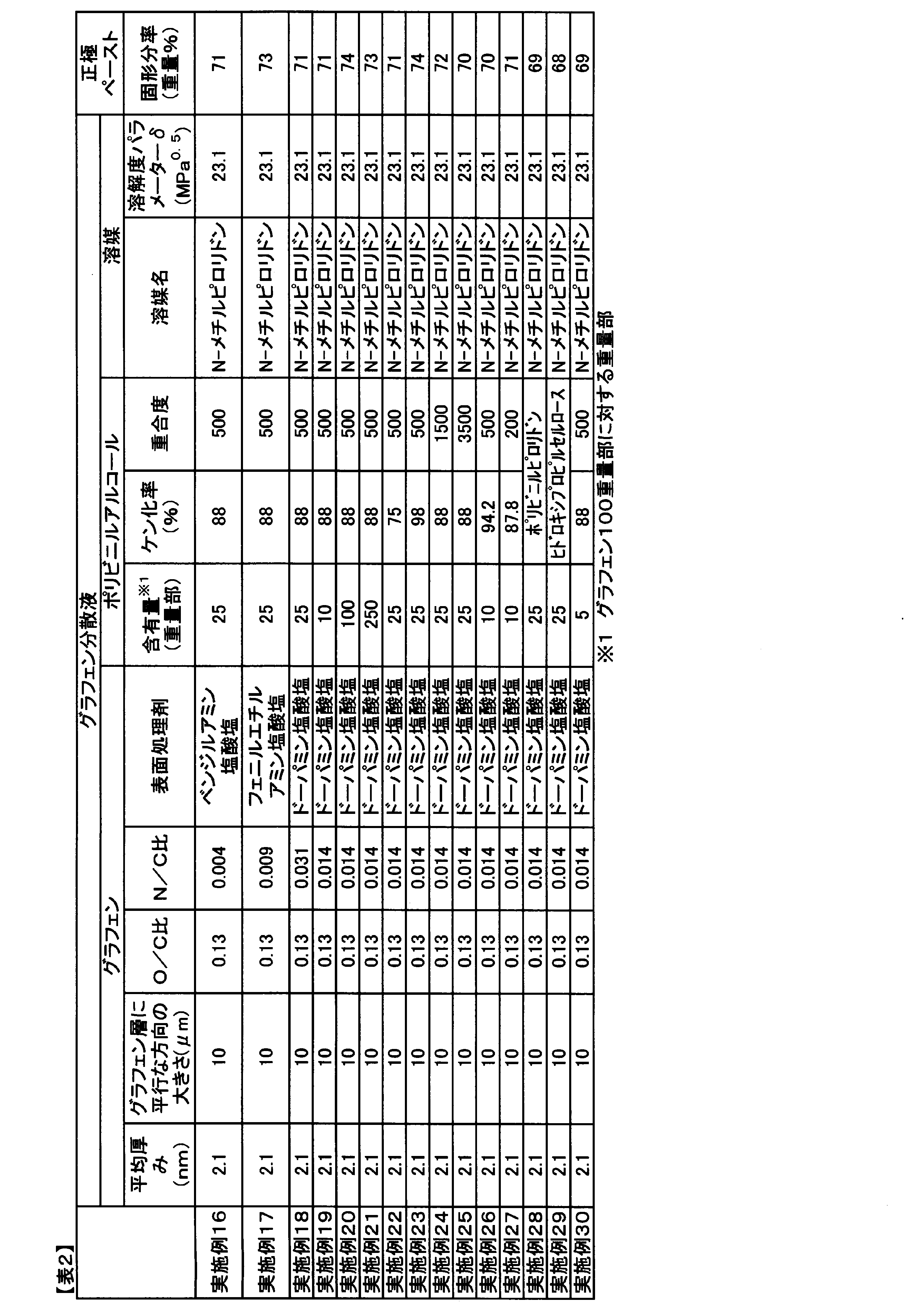


Claims (12)
- グラフェンおよび溶媒を含有するグラフェン分散液であって、前記グラフェンの平均厚みが0.3nm以上10nm以下であり、前記溶媒の溶解度パラメーターδが18MPa0.5以上28MPa0.5以下であり、かつ、グラフェン濃度3重量%に調整したときの、剪断速度10sec-1、温度25℃における粘度が10,000mPa・s以下となる、グラフェン分散液。
- グラフェン濃度3重量%に調整したときの、剪断速度10sec-1、温度25℃における粘度が10mPa・s以上1,000mPa・s以下となる、請求項1に記載のグラフェン分散液。
- グラフェン濃度3重量%に調整したときの、歪み10%、周波数10Hz、温度25℃における貯蔵弾性率および損失弾性率がいずれも0.1Pa以上100Pa以下である、請求項1または2に記載のグラフェン分散液。
- グラフェン濃度3重量%に調整したときの、周波数10Hz、温度25℃における貯蔵弾性率および損失弾性率が、次の式(1)および/または式(2)を満たす、請求項1~3のいずれかに記載のグラフェン分散液;
式(1):G’200/G’10≧1
式(1)中、G’200は歪み200%における貯蔵弾性率、G’10は歪み10%における貯蔵弾性率を表す;
式(2):G’’200/G’’10≧1
式(2)中、G’’200は歪み200%における損失弾性率、G’’10は歪み10%における損失弾性率を表す。 - 前記グラフェンの、X線光電子分光法により測定される炭素に対する酸素の元素比(O/C比)が0.05以上0.35以下である、請求項1~4のいずれかに記載のグラフェン分散液。
- 前記グラフェンの、X線光電子分光法により測定される炭素に対する窒素の元素比(N/C比)が0.005以上0.020以下である、請求項1~5のいずれかに記載のグラフェン分散液。
- 前記分散液がさらにポリビニルアルコール、ポリビニルピロリドンおよびヒドロキシプロピルセルロースから選ばれた高分子を含有する、請求項1~6のいずれかに記載のグラフェン分散液。
- 前記ポリビニルアルコールのケン化率が70%以上100%以下である、請求項7に記載のグラフェン分散液。
- グラフェン100重量部に対して、ポリビニルアルコールを1重量部以上300重量部以下含有する、請求項7または8に記載のグラフェン分散液。
- 前記溶媒が、N,N-ジメチルホルムアミド、N-メチルピロリドンおよびN,N-ジメチルアセトアミドから選ばれた溶媒を含有する、請求項1~9のいずれかに記載のグラフェン分散液。
- 請求項1~10のいずれかに記載のグラフェン分散液と、正極活物質とを含む、正極ペースト。
- 前記正極活物質100重量部に対し、平均厚み0.3nm以上10nm以下のグラフェンを0.05重量部以上2.5重量部以下含有する、請求項11に記載の正極ペースト。
Priority Applications (4)
| Application Number | Priority Date | Filing Date | Title |
|---|---|---|---|
| CN202080074766.8A CN114631202A (zh) | 2019-11-15 | 2020-11-06 | 石墨烯分散液及正极糊料 |
| JP2020563575A JPWO2021095652A1 (ja) | 2019-11-15 | 2020-11-06 | |
| KR1020227015303A KR20220101621A (ko) | 2019-11-15 | 2020-11-06 | 그래핀 분산액 및 정극 페이스트 |
| US17/769,029 US20240105956A1 (en) | 2019-11-15 | 2020-11-06 | Graphene dispersion liquid and positive electrode paste |
Applications Claiming Priority (4)
| Application Number | Priority Date | Filing Date | Title |
|---|---|---|---|
| JP2019206892 | 2019-11-15 | ||
| JP2019-206892 | 2019-11-15 | ||
| JP2019-206893 | 2019-11-15 | ||
| JP2019206893 | 2019-11-15 |
Publications (1)
| Publication Number | Publication Date |
|---|---|
| WO2021095652A1 true WO2021095652A1 (ja) | 2021-05-20 |
Family
ID=75912954
Family Applications (1)
| Application Number | Title | Priority Date | Filing Date |
|---|---|---|---|
| PCT/JP2020/041528 WO2021095652A1 (ja) | 2019-11-15 | 2020-11-06 | グラフェン分散液および正極ペースト |
Country Status (6)
| Country | Link |
|---|---|
| US (1) | US20240105956A1 (ja) |
| JP (1) | JPWO2021095652A1 (ja) |
| KR (1) | KR20220101621A (ja) |
| CN (1) | CN114631202A (ja) |
| TW (1) | TW202125883A (ja) |
| WO (1) | WO2021095652A1 (ja) |
Cited By (1)
| Publication number | Priority date | Publication date | Assignee | Title |
|---|---|---|---|---|
| CN114103298A (zh) * | 2021-11-24 | 2022-03-01 | 高梵(浙江)信息技术有限公司 | 一种用于羽绒服的石墨烯抑菌面料 |
Citations (4)
| Publication number | Priority date | Publication date | Assignee | Title |
|---|---|---|---|---|
| JP2014001098A (ja) * | 2012-06-18 | 2014-01-09 | Mitsubishi Chemicals Corp | グラフェン分散液、グラフェン分散液を用いて形成される膜及び該膜を備える部材 |
| JP2015105200A (ja) * | 2013-11-29 | 2015-06-08 | 積水化学工業株式会社 | 薄片化黒鉛分散液及び薄片化黒鉛の製造方法 |
| WO2017209039A1 (ja) * | 2016-05-31 | 2017-12-07 | 地方独立行政法人東京都立産業技術研究センター | 多層グラフェン分散液、熱物性測定用黒化剤および粉末焼結用離型剤・潤滑剤 |
| JP2019512442A (ja) * | 2016-03-09 | 2019-05-16 | 東レ株式会社 | グラフェン分散液、電極ペーストの製造方法および電極の製造方法 |
Family Cites Families (6)
| Publication number | Priority date | Publication date | Assignee | Title |
|---|---|---|---|---|
| EP2562766A1 (de) | 2011-08-22 | 2013-02-27 | Bayer MaterialScience AG | Kohlenstoffnanoröhren und Graphenplättchen umfassende Dispersionen |
| CN104959050A (zh) * | 2015-04-29 | 2015-10-07 | 北京天恒盛通科技发展有限公司 | 高分散高稳定高浓度高产率的石墨烯分散液及其制备方法 |
| JP6863099B2 (ja) * | 2016-06-06 | 2021-04-21 | 東レ株式会社 | グラフェン/有機溶媒分散液、グラフェン−活物質複合体粒子の製造方法および電極ペーストの製造方法 |
| CN107919475B (zh) * | 2016-10-09 | 2020-10-16 | 上海中聚佳华电池科技有限公司 | 一种石墨烯改性的锂离子电池正极材料及制备方法和应用 |
| JP6982788B2 (ja) | 2017-03-30 | 2021-12-17 | 東レ株式会社 | 二次電池用電極およびその製造方法 |
| JP6755218B2 (ja) | 2017-07-11 | 2020-09-16 | 大日精化工業株式会社 | ナノカーボン分散液 |
-
2020
- 2020-11-06 WO PCT/JP2020/041528 patent/WO2021095652A1/ja active Application Filing
- 2020-11-06 JP JP2020563575A patent/JPWO2021095652A1/ja active Pending
- 2020-11-06 KR KR1020227015303A patent/KR20220101621A/ko unknown
- 2020-11-06 CN CN202080074766.8A patent/CN114631202A/zh active Pending
- 2020-11-06 US US17/769,029 patent/US20240105956A1/en active Pending
- 2020-11-11 TW TW109139284A patent/TW202125883A/zh unknown
Patent Citations (4)
| Publication number | Priority date | Publication date | Assignee | Title |
|---|---|---|---|---|
| JP2014001098A (ja) * | 2012-06-18 | 2014-01-09 | Mitsubishi Chemicals Corp | グラフェン分散液、グラフェン分散液を用いて形成される膜及び該膜を備える部材 |
| JP2015105200A (ja) * | 2013-11-29 | 2015-06-08 | 積水化学工業株式会社 | 薄片化黒鉛分散液及び薄片化黒鉛の製造方法 |
| JP2019512442A (ja) * | 2016-03-09 | 2019-05-16 | 東レ株式会社 | グラフェン分散液、電極ペーストの製造方法および電極の製造方法 |
| WO2017209039A1 (ja) * | 2016-05-31 | 2017-12-07 | 地方独立行政法人東京都立産業技術研究センター | 多層グラフェン分散液、熱物性測定用黒化剤および粉末焼結用離型剤・潤滑剤 |
Cited By (1)
| Publication number | Priority date | Publication date | Assignee | Title |
|---|---|---|---|---|
| CN114103298A (zh) * | 2021-11-24 | 2022-03-01 | 高梵(浙江)信息技术有限公司 | 一种用于羽绒服的石墨烯抑菌面料 |
Also Published As
| Publication number | Publication date |
|---|---|
| JPWO2021095652A1 (ja) | 2021-05-20 |
| KR20220101621A (ko) | 2022-07-19 |
| TW202125883A (zh) | 2021-07-01 |
| CN114631202A (zh) | 2022-06-14 |
| US20240105956A1 (en) | 2024-03-28 |
Similar Documents
| Publication | Publication Date | Title |
|---|---|---|
| TWI682896B (zh) | 表面處理石墨烯及其製造方法、表面處理石墨烯/有機溶劑分散液及其製造方法、表面處理石墨烯 - 電極活性物質的複合體粒子及電極糊 | |
| TWI694054B (zh) | 石墨烯分散液及其製造方法、石墨烯-電極活性物質複合體粒子的製造方法以及電極糊的製造方法 | |
| TWI709527B (zh) | 石墨烯分散體、電極糊之製造方法以及電極之製造方法 | |
| JP6152925B1 (ja) | グラフェン分散液およびその製造方法、グラフェン−活物質複合体粒子の製造方法ならびに電極用ペーストの製造方法 | |
| TWI694053B (zh) | 石墨烯/有機溶劑分散液及其製造方法、以及鋰離子電池用電極的製造方法 | |
| EP3205624A1 (en) | Graphene powder, electrode paste for lithium ion battery and electrode for lithium ion battery | |
| KR102421959B1 (ko) | 이차 전지용 전극 | |
| JP6879150B2 (ja) | 導電助剤分散液、その利用およびその製造方法 | |
| JP6863099B2 (ja) | グラフェン/有機溶媒分散液、グラフェン−活物質複合体粒子の製造方法および電極ペーストの製造方法 | |
| KR102320435B1 (ko) | 그래핀 분산액 및 그의 제조 방법 그리고 이차 전지용 전극 | |
| JP2018174134A (ja) | 二次電池用電極およびその製造方法 | |
| WO2021095652A1 (ja) | グラフェン分散液および正極ペースト | |
| JP2017073363A (ja) | 電極合剤スラリーの製造方法 | |
| JP2022167301A (ja) | リチウムイオン二次電池用正極 | |
| WO2021095651A1 (ja) | グラフェン分散液、正極ペーストおよびリチウムイオン電池正極 | |
| JP2020164403A (ja) | グラフェン分散液および二次電池用電極 | |
| JP2022071849A (ja) | グラフェン分散液およびリチウムイオン電池正極 | |
| JP2022174846A (ja) | リチウムイオン二次電池正極用ペースト | |
| JP2021002518A (ja) | 二次電池用電極ペーストの製造方法 |
Legal Events
| Date | Code | Title | Description |
|---|---|---|---|
| ENP | Entry into the national phase |
Ref document number: 2020563575 Country of ref document: JP Kind code of ref document: A |
|
| 121 | Ep: the epo has been informed by wipo that ep was designated in this application |
Ref document number: 20888256 Country of ref document: EP Kind code of ref document: A1 |
|
| WWE | Wipo information: entry into national phase |
Ref document number: 17769029 Country of ref document: US |
|
| NENP | Non-entry into the national phase |
Ref country code: DE |
|
| 122 | Ep: pct application non-entry in european phase |
Ref document number: 20888256 Country of ref document: EP Kind code of ref document: A1 |