WO2021095237A1 - 冷熱源ユニットおよび冷凍サイクル装置 - Google Patents
冷熱源ユニットおよび冷凍サイクル装置 Download PDFInfo
- Publication number
- WO2021095237A1 WO2021095237A1 PCT/JP2019/044891 JP2019044891W WO2021095237A1 WO 2021095237 A1 WO2021095237 A1 WO 2021095237A1 JP 2019044891 W JP2019044891 W JP 2019044891W WO 2021095237 A1 WO2021095237 A1 WO 2021095237A1
- Authority
- WO
- WIPO (PCT)
- Prior art keywords
- compressor
- control
- control device
- heat source
- source unit
- Prior art date
- Legal status (The legal status is an assumption and is not a legal conclusion. Google has not performed a legal analysis and makes no representation as to the accuracy of the status listed.)
- Ceased
Links
Images


Classifications
-
- F—MECHANICAL ENGINEERING; LIGHTING; HEATING; WEAPONS; BLASTING
- F25—REFRIGERATION OR COOLING; COMBINED HEATING AND REFRIGERATION SYSTEMS; HEAT PUMP SYSTEMS; MANUFACTURE OR STORAGE OF ICE; LIQUEFACTION SOLIDIFICATION OF GASES
- F25B—REFRIGERATION MACHINES, PLANTS OR SYSTEMS; COMBINED HEATING AND REFRIGERATION SYSTEMS; HEAT PUMP SYSTEMS
- F25B49/00—Arrangement or mounting of control or safety devices
- F25B49/005—Arrangement or mounting of control or safety devices of safety devices
-
- F—MECHANICAL ENGINEERING; LIGHTING; HEATING; WEAPONS; BLASTING
- F04—POSITIVE - DISPLACEMENT MACHINES FOR LIQUIDS; PUMPS FOR LIQUIDS OR ELASTIC FLUIDS
- F04B—POSITIVE-DISPLACEMENT MACHINES FOR LIQUIDS; PUMPS
- F04B49/00—Control, e.g. of pump delivery, or pump pressure of, or safety measures for, machines, pumps, or pumping installations, not otherwise provided for, or of interest apart from, groups F04B1/00 - F04B47/00
- F04B49/02—Stopping, starting, unloading or idling control
-
- F—MECHANICAL ENGINEERING; LIGHTING; HEATING; WEAPONS; BLASTING
- F04—POSITIVE - DISPLACEMENT MACHINES FOR LIQUIDS; PUMPS FOR LIQUIDS OR ELASTIC FLUIDS
- F04B—POSITIVE-DISPLACEMENT MACHINES FOR LIQUIDS; PUMPS
- F04B49/00—Control, e.g. of pump delivery, or pump pressure of, or safety measures for, machines, pumps, or pumping installations, not otherwise provided for, or of interest apart from, groups F04B1/00 - F04B47/00
- F04B49/06—Control using electricity
- F04B49/065—Control using electricity and making use of computers
-
- F—MECHANICAL ENGINEERING; LIGHTING; HEATING; WEAPONS; BLASTING
- F24—HEATING; RANGES; VENTILATING
- F24F—AIR-CONDITIONING; AIR-HUMIDIFICATION; VENTILATION; USE OF AIR CURRENTS FOR SCREENING
- F24F11/00—Control or safety arrangements
- F24F11/30—Control or safety arrangements for purposes related to the operation of the system, e.g. for safety or monitoring
- F24F11/32—Responding to malfunctions or emergencies
- F24F11/37—Resuming operation, e.g. after power outages; Emergency starting
-
- F—MECHANICAL ENGINEERING; LIGHTING; HEATING; WEAPONS; BLASTING
- F25—REFRIGERATION OR COOLING; COMBINED HEATING AND REFRIGERATION SYSTEMS; HEAT PUMP SYSTEMS; MANUFACTURE OR STORAGE OF ICE; LIQUEFACTION SOLIDIFICATION OF GASES
- F25B—REFRIGERATION MACHINES, PLANTS OR SYSTEMS; COMBINED HEATING AND REFRIGERATION SYSTEMS; HEAT PUMP SYSTEMS
- F25B49/00—Arrangement or mounting of control or safety devices
- F25B49/02—Arrangement or mounting of control or safety devices for compression type machines, plants or systems
-
- F—MECHANICAL ENGINEERING; LIGHTING; HEATING; WEAPONS; BLASTING
- F04—POSITIVE - DISPLACEMENT MACHINES FOR LIQUIDS; PUMPS FOR LIQUIDS OR ELASTIC FLUIDS
- F04C—ROTARY-PISTON, OR OSCILLATING-PISTON, POSITIVE-DISPLACEMENT MACHINES FOR LIQUIDS; ROTARY-PISTON, OR OSCILLATING-PISTON, POSITIVE-DISPLACEMENT PUMPS
- F04C28/00—Control of, monitoring of, or safety arrangements for, pumps or pumping installations specially adapted for elastic fluids
- F04C28/06—Control of, monitoring of, or safety arrangements for, pumps or pumping installations specially adapted for elastic fluids specially adapted for stopping, starting, idling or no-load operation
-
- F—MECHANICAL ENGINEERING; LIGHTING; HEATING; WEAPONS; BLASTING
- F04—POSITIVE - DISPLACEMENT MACHINES FOR LIQUIDS; PUMPS FOR LIQUIDS OR ELASTIC FLUIDS
- F04C—ROTARY-PISTON, OR OSCILLATING-PISTON, POSITIVE-DISPLACEMENT MACHINES FOR LIQUIDS; ROTARY-PISTON, OR OSCILLATING-PISTON, POSITIVE-DISPLACEMENT PUMPS
- F04C28/00—Control of, monitoring of, or safety arrangements for, pumps or pumping installations specially adapted for elastic fluids
- F04C28/28—Safety arrangements; Monitoring
-
- F—MECHANICAL ENGINEERING; LIGHTING; HEATING; WEAPONS; BLASTING
- F24—HEATING; RANGES; VENTILATING
- F24F—AIR-CONDITIONING; AIR-HUMIDIFICATION; VENTILATION; USE OF AIR CURRENTS FOR SCREENING
- F24F2140/00—Control inputs relating to system states
- F24F2140/50—Load
-
- F—MECHANICAL ENGINEERING; LIGHTING; HEATING; WEAPONS; BLASTING
- F25—REFRIGERATION OR COOLING; COMBINED HEATING AND REFRIGERATION SYSTEMS; HEAT PUMP SYSTEMS; MANUFACTURE OR STORAGE OF ICE; LIQUEFACTION SOLIDIFICATION OF GASES
- F25B—REFRIGERATION MACHINES, PLANTS OR SYSTEMS; COMBINED HEATING AND REFRIGERATION SYSTEMS; HEAT PUMP SYSTEMS
- F25B2500/00—Problems to be solved
- F25B2500/26—Problems to be solved characterised by the startup of the refrigeration cycle
-
- F—MECHANICAL ENGINEERING; LIGHTING; HEATING; WEAPONS; BLASTING
- F25—REFRIGERATION OR COOLING; COMBINED HEATING AND REFRIGERATION SYSTEMS; HEAT PUMP SYSTEMS; MANUFACTURE OR STORAGE OF ICE; LIQUEFACTION SOLIDIFICATION OF GASES
- F25B—REFRIGERATION MACHINES, PLANTS OR SYSTEMS; COMBINED HEATING AND REFRIGERATION SYSTEMS; HEAT PUMP SYSTEMS
- F25B2500/00—Problems to be solved
- F25B2500/28—Means for preventing liquid refrigerant entering into the compressor
-
- F—MECHANICAL ENGINEERING; LIGHTING; HEATING; WEAPONS; BLASTING
- F25—REFRIGERATION OR COOLING; COMBINED HEATING AND REFRIGERATION SYSTEMS; HEAT PUMP SYSTEMS; MANUFACTURE OR STORAGE OF ICE; LIQUEFACTION SOLIDIFICATION OF GASES
- F25B—REFRIGERATION MACHINES, PLANTS OR SYSTEMS; COMBINED HEATING AND REFRIGERATION SYSTEMS; HEAT PUMP SYSTEMS
- F25B2600/00—Control issues
- F25B2600/01—Timing
-
- F—MECHANICAL ENGINEERING; LIGHTING; HEATING; WEAPONS; BLASTING
- F25—REFRIGERATION OR COOLING; COMBINED HEATING AND REFRIGERATION SYSTEMS; HEAT PUMP SYSTEMS; MANUFACTURE OR STORAGE OF ICE; LIQUEFACTION SOLIDIFICATION OF GASES
- F25B—REFRIGERATION MACHINES, PLANTS OR SYSTEMS; COMBINED HEATING AND REFRIGERATION SYSTEMS; HEAT PUMP SYSTEMS
- F25B2600/00—Control issues
- F25B2600/02—Compressor control
-
- F—MECHANICAL ENGINEERING; LIGHTING; HEATING; WEAPONS; BLASTING
- F25—REFRIGERATION OR COOLING; COMBINED HEATING AND REFRIGERATION SYSTEMS; HEAT PUMP SYSTEMS; MANUFACTURE OR STORAGE OF ICE; LIQUEFACTION SOLIDIFICATION OF GASES
- F25B—REFRIGERATION MACHINES, PLANTS OR SYSTEMS; COMBINED HEATING AND REFRIGERATION SYSTEMS; HEAT PUMP SYSTEMS
- F25B2600/00—Control issues
- F25B2600/23—Time delays
-
- F—MECHANICAL ENGINEERING; LIGHTING; HEATING; WEAPONS; BLASTING
- F25—REFRIGERATION OR COOLING; COMBINED HEATING AND REFRIGERATION SYSTEMS; HEAT PUMP SYSTEMS; MANUFACTURE OR STORAGE OF ICE; LIQUEFACTION SOLIDIFICATION OF GASES
- F25B—REFRIGERATION MACHINES, PLANTS OR SYSTEMS; COMBINED HEATING AND REFRIGERATION SYSTEMS; HEAT PUMP SYSTEMS
- F25B2700/00—Sensing or detecting of parameters; Sensors therefor
- F25B2700/21—Temperatures
- F25B2700/2106—Temperatures of fresh outdoor air
-
- F—MECHANICAL ENGINEERING; LIGHTING; HEATING; WEAPONS; BLASTING
- F25—REFRIGERATION OR COOLING; COMBINED HEATING AND REFRIGERATION SYSTEMS; HEAT PUMP SYSTEMS; MANUFACTURE OR STORAGE OF ICE; LIQUEFACTION SOLIDIFICATION OF GASES
- F25B—REFRIGERATION MACHINES, PLANTS OR SYSTEMS; COMBINED HEATING AND REFRIGERATION SYSTEMS; HEAT PUMP SYSTEMS
- F25B2700/00—Sensing or detecting of parameters; Sensors therefor
- F25B2700/21—Temperatures
- F25B2700/2117—Temperatures of an evaporator
Definitions
- the present invention relates to a cold heat source unit and a refrigeration cycle device.
- liquid refrigerant in the unit may return to the accumulator at the time of starting after defrosting.
- a large amount of liquid refrigerant flows inside the oil return circuit installed at the bottom of the accumulator, and this liquid refrigerant excessively flows from the oil return circuit into the compressor (hereinafter referred to as "liquid back"). May occur.
- liquid back the compressor
- Patent Document 1 Japanese Patent Application Laid-Open No. 6-34224 states that the compressor current value is maintained at a certain value or more for a certain period of time by a current value comparison unit in order to prevent a compressor failure due to an overcurrent state. Then, the compressor is temporarily stopped, the compressor is restarted after a certain period of time after the compressor is stopped, and the entire operation is stopped after the same operation is repeated a certain number of times.
- the compressor may temporarily stop due to an overcurrent state due to an increase in the motor load of the compressor due to the liquid compression operation. ..
- Patent Document 1 the compressor is attempted to be restarted after a certain time after the compressor is stopped.
- startup retry the attempt to restart the compressor will be referred to as a "startup retry".
- the present invention has been made to solve the above-mentioned problems, and when the compressor is stopped due to an overcurrent, the cold heat source unit and the refrigeration cycle in which the probability of successful restart of the compressor is improved.
- the purpose is to provide the device.
- the present disclosure relates to a cold heat source unit connected to a load device and constituting a refrigeration cycle device.
- the cold heat source unit includes a compressor and a control device for controlling the compressor.
- the control device detects an overload of the compressor, the control device executes a first start retry control in which the compressor is stopped for the first time and then the compressor is restarted.
- the control device stops the compressor for a second time longer than the first time, and then restarts the compressor. Take control.
- the waiting time until the compressor starts is lengthened and the compressor is restarted. Therefore, the liquid refrigerant in the compressor is discharged, and the probability of successful restart is improved.
- FIG. 1 is a diagram showing a refrigerant circuit of the refrigeration cycle device 200 according to the present embodiment.
- the refrigeration cycle device 200 includes a cold heat source unit 100 and a load device 110.
- the "cold heat source unit” is sometimes called a "heat source unit”.
- the load device 110 includes an expansion valve 3 and a first heat exchanger (hereinafter referred to as an evaporator 4).
- the cold heat source unit 100 is connected to the load device 110 to form the refrigeration cycle device 200.
- the cold heat source unit 100 includes a compressor 1, a second heat exchanger (hereinafter referred to as a condenser 2), a heater 40, and a control device 30 for controlling the compressor 1 and the heater 40.
- the control device 30 includes a CPU (Central Processing Unit) 31, a memory 32 (ROM (Read Only Memory) and a RAM (Random Access Memory)), an input / output device (not shown) for inputting various signals, and the like. Will be done.
- the CPU 31 expands the program stored in the ROM into a RAM or the like and executes the program.
- the program stored in the ROM is a program in which the processing procedure of the control device 30 is described.
- the control device 30 executes control of each device in the cold heat source unit 100 according to these programs. This control is not limited to software processing, but can also be processed by dedicated hardware (electronic circuit).
- the thermistor 5 for detecting the suction temperature and the temperature of the lower part of the outer shell of the compressor 1 or the temperature of the refrigerating machine oil staying in the housing of the compressor 1 (hereinafter referred to as “under-shell temperature”). ) Is attached, and a current sensor 7 for detecting an overcurrent is attached.
- the compressor 1 compresses the refrigerant gas into a high-pressure gas, and the high-pressure gas refrigerant flows into the condenser 2.
- the condenser 2 heat is released from the refrigerant, and the high-pressure gas refrigerant condenses to become a high-pressure liquid refrigerant.
- the high-pressure liquid refrigerant flows through the expansion valve 3.
- the high-pressure liquid refrigerant is depressurized by the expansion valve 3, and the low-pressure liquid refrigerant flows to the evaporator 4.
- the liquid refrigerant evaporates, and a cooling action of removing heat from the surroundings is performed.
- the evaporated gas refrigerant returns to the compressor 1 and the refrigerant circuit is established.
- the compressor 1 when an overload is detected, the compressor 1 is stopped, and by securing a sufficient stop time, the amount of liquid in the compressor 1 is reduced, and start failure at the time of start retry is suppressed.
- the control device 30 detects that the load of the compressor 1 is an overload when an overcurrent is detected by the current sensor 7.
- the control device 30 detects an overload of the compressor 1, it executes a first start retry control in which the compressor 1 is stopped for a first time and then the compressor 1 is restarted. Then, when the number of times the first start retry control is executed exceeds the determination value, the control device 30 stops the compressor 1 for a second time longer than the first time, and then restarts the compressor 1. 2 Execute start retry control.
- the stop time is not limited to the following, but for example, the first hour may be 3 minutes and the second hour may be 30 minutes.
- FIG. 2 is a diagram showing the relationship between the stop time of the compressor and the rate of change in the amount of liquid in the compressor.
- the compressor stop time in one liquid discharge promotion control implementation is determined in consideration of the relationship shown in FIG. 2 and the temperature rise in the refrigerator due to the compressor stop.
- the liquid discharge promotion control is performed up to twice, and the compressor stop time in one liquid discharge promotion control execution is set to 30 minutes.
- FIG. 3 is a flowchart for explaining the control for executing the start retry of the compressor. The improvement of the start failure of the overcurrent abnormality will be described with reference to this flowchart.
- step S1 the control device 30 determines whether or not the start retry control due to the overcurrent has been performed five times.
- step S10 If the total number of start retry controls has reached 5 (YES in S1), the control device 30 proceeds to step S10 to prevent further start retry control from being executed, and the stop is abnormal. Is notified. For example, it is possible for the user to recognize that an abnormal stop has occurred due to lighting of a light emitting diode or the like.
- control device 30 determines in step S2 whether the total number of start retry controls has reached 3 times.
- step S11 If the total number of start retry controls has not reached 3 (NO in S2), the control device 30 proceeds to step S11 and performs normal start retry control of the compressor. For example, in this case, after keeping the compressor stopped for 3 minutes, the compressor 1 is energized and an attempt is made to restart the compressor. This 3 minutes is a time defined so that the start and stop are not repeated when the amount of liquid refrigerant in the compressor 1 is small.
- step S2 the control after step S5, which delays the start of the compressor 1 more than before, is executed.
- the compressor 1 as before is not performed without performing the processing after step S5. May be repeated up to 5 times. For example, the following cases are assumed. -When it is necessary to prioritize cooling, such as when the temperature inside the refrigerator exceeds a certain threshold value due to defrosting operation, or when the refrigerating capacity of the cold heat source unit is insufficient. ⁇ When liquid back does not occur. -When the refrigerating machine oil of the compressor 1 is insufficient and the oil return control is started. -When there is a risk that the pressure on the discharge side and the suction side of the compressor 1 will be reversed. ⁇ When the low pressure pressure sensor detects an open or short circuit and becomes abnormal.
- step S3 the determination in steps S3 and S4 is performed before shifting to the process in step S5.
- step S3 the control device 30 measures the temperature with the thermistor 5 and the thermistor 6, and the superheat degree of the suction refrigerant (suction SH), the temperature under the shell, and the superheat degree of the refrigerating machine oil staying in the housing of the compressor 1 (hereinafter referred to as , Under-shell SH) determines whether or not the state of being lower than the reference value corresponding to each for a certain period of time (for example, 3 minutes) continues. As a result, the control device 30 determines whether or not liquid backing has occurred.
- the degree of superheat is the temperature difference between the actually measured refrigerant temperature and the saturated gas temperature corresponding to the measured pressure.
- the control device 30 detects that liquid backing has occurred, for example, when the inhaled SH is 10 K lower than the target value for 3 consecutive minutes.
- step S12 the control device 30 performs a normal start retry of the compressor. Control. For example, in this case, after keeping the compressor stopped for 3 minutes, the compressor 1 is energized and an attempt is made to restart the compressor.
- step S4 the control device 30 determines whether or not the evaporation temperature ET is lower than the target evaporation temperature ETm + 10K (Kelvin). If the difference between the evaporation temperature ET and the target evaporation temperature ETm is 10 K or less, it can be determined that the cooling inside the refrigerator can be maintained even if the compressor is stopped for a certain period of time.
- the evaporation temperature ET may be measured by providing a temperature sensor in the evaporator 4, but may be substituted by the detection temperature of the thermistor 5 that detects the suction temperature.
- the control device 30 performs normal start retry control of the compressor in step S13. For example, in this case, after keeping the compressor stopped for 3 minutes, the compressor 1 is energized and an attempt is made to restart the compressor. For example, if the temperature inside the refrigerator is high after defrosting operation, or if multiple load units are connected and the refrigerating capacity of the cold heat source unit is insufficient and the temperature inside the refrigerator is high, the 30-minute downtime is Because it's too long.
- the control device 30 starts the liquid discharge promotion control that delays the start of the compressor 1 in step S5. Then, the measurement of the time after the compressor 1 is stopped is started. The time during measurement from when the compressor 1 is stopped to when it is restarted is referred to as a "delay time".
- the control device 30 keeps the compressor 1 stopped until the delay time reaches the second time (for example, 30 minutes) in order to sufficiently reduce the liquid refrigerant in the compressor 1. This second time is set longer than the first time (for example, 3 minutes), which is the stop time in steps S11, S12, and S13.
- step S6 it is determined whether or not the set time (for example, 30 minutes) has elapsed.
- the set time for example, 30 minutes
- the start retry of the compressor 1 is executed in step S14.
- step S7 it is determined whether or not there is a request to start the oil return control.
- the oil return control is requested when the refrigerating machine oil in the compressor 1 is insufficient in order to prevent seizure of the compressor 1.
- step S15 When there is a request to start the oil return control (YES in S7), the start retry of the compressor 1 is executed in step S15.
- step S8 it is determined whether or not there is a request to start the high / low voltage reversal prevention control.
- the high / low pressure reversal prevention control is requested to start when it is detected that the pressure on the suction port side of the compressor 1 is higher than the pressure on the discharge port side.
- step S9 it is determined whether or not the evaporation temperature ET is continuously equal to or higher than the target evaporation temperature ETm + 10K (Kelvin) for 3 minutes.
- step S9 If the time when the target evaporation temperature is ETm + 10K (Kelvin) or higher is less than 3 minutes (NO in S9), the process is returned to step S6, and the measurement of the delay time until the start retry of the compressor is started continues. Will be done.
- step S18 the control device 30 determines whether or not the start-up of the compressor 1 is normally completed.
- control device 30 increases the number of activation retries by 1 in step S19, and executes the process again from step S1.
- step S10 if the compressor does not start even if the start retry is performed after the liquid refrigerant outflow promotion control is performed twice, the operation is stopped in step S10. At this time, it can be determined that the cause of the overcurrent abnormality detection is not due to the liquid back.
- step S18 the start of the compressor 1 is determined to be successful (YES in S18)
- the count of the number of start retries is initialized in step S20
- the normal compression is performed in step S21. The process is returned to the control routine in the normal operating state of the machine 1.
- the heater 40 may be used in combination for heating, but when the outside air temperature is high, the heater 40 may be stopped for energy saving.
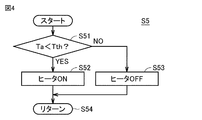
- FIG. 4 is a flowchart for explaining the energization control of the heater at the start of the liquid discharge promotion control.
- the control device 30 acquires the outside air temperature Ta from the outside air temperature sensor 8 and determines whether or not the outside air temperature Ta is lower than the first threshold temperature Tth.
- the control device 30 When Ta ⁇ Tth is established (YES in S51), the control device 30 energizes the heater 40, and the heater 40 heats the liquid refrigerant inside the compressor 1 for a delay time of 30 minutes. On the other hand, when Ta ⁇ Tth is not established (NO in S51), the control device 30 does not energize the heater 40, the heater is off for a delay time of 30 minutes, and the compressor 1 is affected by the outside air temperature. Wait for the internal liquid refrigerant to warm up.
- the stop time of the compressor 1 at the time of the fourth and subsequent start retries is set to be longer than that at the time of the first start retry.
- the liquid refrigerant in the compressor 1 can be heated by the heating by the heater 40 or the outside air temperature, and can be sufficiently expelled from the compressor 1. In this way, the amount of liquid in the compressor 1 can be reduced, and a start failure due to an overcurrent abnormality at the time of start retry can be suppressed.
- the present embodiment relates to a cold heat source unit 100 connected to a load device 110 and constituting a refrigeration cycle device 200.
- the cold heat source unit 100 includes a compressor 1 and a control device 30 for controlling the compressor 1.
- the control device 30 detects an overload of the compressor 1, it executes a first start retry control in which the compressor 1 is stopped for a first time and then the compressor 1 is restarted.
- the control device 30 stops the compressor 1 for a second time longer than the first time, and then restarts the compressor 1. 2 Execute start retry control.
- the second time is the time required for the amount of liquid in the compressor 1 to decrease and the compressor 1 to be restartable.
- the cold heat source unit 100 further includes a heater 40 configured to heat the liquid refrigerant inside the compressor 1.
- the control device 30 is configured to heat the liquid refrigerant by the heater 40 when executing the second start retry control.
- the heater 40 further promotes the vaporization of the liquid refrigerant in the compressor 1 and reduces the amount of the liquid.
- the overload at startup is eliminated, and the possibility of successfully restarting the compressor 1 is further increased.
- the control device 30 when the outside air temperature Ta does not exceed the first threshold temperature Tth, the control device 30 performs the second activation while executing the heating of the liquid refrigerant by the heater 40. Execute retry control. When the outside air temperature Ta exceeds the first threshold temperature Tth, the control device 30 executes the second start retry control with the heating of the liquid refrigerant by the heater 40 stopped.
- the control device 30 makes a first start retry when the difference between the refrigerant evaporation temperature ET and the target evaporation temperature ETm is less than the second threshold temperature (for example, 10K). Take control.
- the second threshold temperature for example, 10K
- the evaporation temperature ET becomes higher than the target evaporation temperature ETm to some extent. , It is possible to avoid a further rise in the temperature inside the refrigerator due to delaying the start-up time.
- the number of times the first start retry control is executed is the first determination value (1st determination value. Even if it exceeds (for example, 3 times), the first start retry control is executed.
- the control device 30 sucks the liquid refrigerant into the compressor 1 based on at least one of the degree of superheat of the refrigerant sucked by the compressor 1, the temperature under the shell of the compressor 1, and the degree of superheat of the refrigerant in the compressor 1. Judge the presence or absence.
- the control device 30 when the control device 30 fails to start the compressor 1 when the second start retry control is performed, the second start retry control is repeatedly executed, and the control device 30 controls the second start retry control.
- the compressor 1 When the number of times of execution exceeds the second judgment value, the compressor 1 is set to the stopped state, and the first judgment value is 60% of the total of the first judgment value and the second judgment value. It is a judgment value.
- the control device 30 is a compressor. Set 1 to the stopped state. Therefore, since the first determination value is 3 and the second determination value is 2, the first determination value is 60% of the total of the first determination value and the second determination value. Since the effect of liquid discharge can be most expected when the vehicle is stopped for a total of 60 minutes (30 minutes x 2 times), the liquid is discharged when 3 out of 5 start retries are exceeded.
Landscapes
- Engineering & Computer Science (AREA)
- Mechanical Engineering (AREA)
- General Engineering & Computer Science (AREA)
- Physics & Mathematics (AREA)
- Thermal Sciences (AREA)
- Computer Hardware Design (AREA)
- Chemical & Material Sciences (AREA)
- Combustion & Propulsion (AREA)
- Air Conditioning Control Device (AREA)
Priority Applications (4)
| Application Number | Priority Date | Filing Date | Title |
|---|---|---|---|
| CN201980102102.5A CN114729765B (zh) | 2019-11-15 | 2019-11-15 | 冷热源单元以及制冷循环装置 |
| JP2021555751A JP7399182B2 (ja) | 2019-11-15 | 2019-11-15 | 冷熱源ユニットおよび冷凍サイクル装置 |
| PCT/JP2019/044891 WO2021095237A1 (ja) | 2019-11-15 | 2019-11-15 | 冷熱源ユニットおよび冷凍サイクル装置 |
| EP19952629.4A EP4060250B1 (en) | 2019-11-15 | 2019-11-15 | Cold heat source unit and refrigeration circuit device |
Applications Claiming Priority (1)
| Application Number | Priority Date | Filing Date | Title |
|---|---|---|---|
| PCT/JP2019/044891 WO2021095237A1 (ja) | 2019-11-15 | 2019-11-15 | 冷熱源ユニットおよび冷凍サイクル装置 |
Publications (1)
| Publication Number | Publication Date |
|---|---|
| WO2021095237A1 true WO2021095237A1 (ja) | 2021-05-20 |
Family
ID=75911485
Family Applications (1)
| Application Number | Title | Priority Date | Filing Date |
|---|---|---|---|
| PCT/JP2019/044891 Ceased WO2021095237A1 (ja) | 2019-11-15 | 2019-11-15 | 冷熱源ユニットおよび冷凍サイクル装置 |
Country Status (4)
| Country | Link |
|---|---|
| EP (1) | EP4060250B1 (https=) |
| JP (1) | JP7399182B2 (https=) |
| CN (1) | CN114729765B (https=) |
| WO (1) | WO2021095237A1 (https=) |
Cited By (2)
| Publication number | Priority date | Publication date | Assignee | Title |
|---|---|---|---|---|
| CN113418327A (zh) * | 2021-05-28 | 2021-09-21 | 青岛海尔空调电子有限公司 | 冷藏冷冻机组的回油控制方法及冷藏冷冻机组 |
| CN113432343A (zh) * | 2021-05-28 | 2021-09-24 | 青岛海尔空调电子有限公司 | 冷藏冷冻机组的回油控制方法及冷藏冷冻机组 |
Families Citing this family (1)
| Publication number | Priority date | Publication date | Assignee | Title |
|---|---|---|---|---|
| EP4629747A1 (en) * | 2024-03-29 | 2025-10-08 | Thermo King LLC | Heating systems for a refrigeration system |
Citations (6)
| Publication number | Priority date | Publication date | Assignee | Title |
|---|---|---|---|---|
| JPH0493558A (ja) * | 1990-08-06 | 1992-03-26 | Daikin Ind Ltd | 冷凍装置の運転制御装置 |
| JPH0634224A (ja) | 1992-07-17 | 1994-02-08 | Matsushita Electric Ind Co Ltd | 暖冷房機 |
| JPH08261571A (ja) * | 1995-03-20 | 1996-10-11 | Matsushita Electric Ind Co Ltd | 圧縮式冷凍装置の起動方法 |
| JPH09149547A (ja) * | 1995-11-24 | 1997-06-06 | Matsushita Electric Ind Co Ltd | 空気調和機の運転制御装置と運転制御方法 |
| JP2000105011A (ja) * | 1998-09-30 | 2000-04-11 | Daikin Ind Ltd | 二元冷凍装置 |
| JP2009216000A (ja) * | 2008-03-11 | 2009-09-24 | Hitachi Industrial Equipment Systems Co Ltd | インバータ圧縮機の制御方法及びインバータ圧縮機 |
Family Cites Families (14)
| Publication number | Priority date | Publication date | Assignee | Title |
|---|---|---|---|---|
| JPH06123514A (ja) * | 1992-10-12 | 1994-05-06 | Matsushita Electric Ind Co Ltd | 暖冷房機 |
| JPH10205895A (ja) * | 1997-01-28 | 1998-08-04 | Matsushita Refrig Co Ltd | 冷凍サイクル制御装置 |
| JPH11108471A (ja) * | 1997-10-02 | 1999-04-23 | Mitsubishi Heavy Ind Ltd | 空気調和機 |
| JP4327936B2 (ja) | 1999-04-08 | 2009-09-09 | 三菱電機株式会社 | ヒートポンプ式冷凍装置 |
| US6119469A (en) * | 1999-06-14 | 2000-09-19 | Spx Corporation | Programmable electronic start-up delay for refrigeration units |
| US6578373B1 (en) * | 2000-09-21 | 2003-06-17 | William J. Barbier | Rate of change detector for refrigerant floodback |
| KR100484800B1 (ko) * | 2002-06-19 | 2005-04-22 | 엘지전자 주식회사 | 공기조화기의 압축기 동작방법 |
| JP4273492B2 (ja) | 2003-12-18 | 2009-06-03 | 三菱電機株式会社 | 空気調和装置及び冷凍装置 |
| JP5558132B2 (ja) * | 2010-02-16 | 2014-07-23 | 三菱電機株式会社 | 冷凍機及びこの冷凍機が接続された冷凍装置 |
| JP5342528B2 (ja) * | 2010-09-25 | 2013-11-13 | 日立アプライアンス株式会社 | アクティブフィルタを備えた空気調和装置 |
| JP6440930B2 (ja) | 2013-06-20 | 2018-12-19 | 三菱重工サーマルシステムズ株式会社 | 空気調和機及び空気調和機の制御方法 |
| JP6403907B2 (ja) * | 2015-12-11 | 2018-10-10 | 三菱電機株式会社 | 冷凍サイクル装置 |
| JP6715945B2 (ja) * | 2016-10-17 | 2020-07-01 | 三菱電機株式会社 | 空気調和機 |
| EP3575708B1 (en) * | 2017-01-25 | 2023-11-01 | Mitsubishi Electric Corporation | Refrigeration cycle device |
-
2019
- 2019-11-15 WO PCT/JP2019/044891 patent/WO2021095237A1/ja not_active Ceased
- 2019-11-15 EP EP19952629.4A patent/EP4060250B1/en active Active
- 2019-11-15 JP JP2021555751A patent/JP7399182B2/ja active Active
- 2019-11-15 CN CN201980102102.5A patent/CN114729765B/zh active Active
Patent Citations (6)
| Publication number | Priority date | Publication date | Assignee | Title |
|---|---|---|---|---|
| JPH0493558A (ja) * | 1990-08-06 | 1992-03-26 | Daikin Ind Ltd | 冷凍装置の運転制御装置 |
| JPH0634224A (ja) | 1992-07-17 | 1994-02-08 | Matsushita Electric Ind Co Ltd | 暖冷房機 |
| JPH08261571A (ja) * | 1995-03-20 | 1996-10-11 | Matsushita Electric Ind Co Ltd | 圧縮式冷凍装置の起動方法 |
| JPH09149547A (ja) * | 1995-11-24 | 1997-06-06 | Matsushita Electric Ind Co Ltd | 空気調和機の運転制御装置と運転制御方法 |
| JP2000105011A (ja) * | 1998-09-30 | 2000-04-11 | Daikin Ind Ltd | 二元冷凍装置 |
| JP2009216000A (ja) * | 2008-03-11 | 2009-09-24 | Hitachi Industrial Equipment Systems Co Ltd | インバータ圧縮機の制御方法及びインバータ圧縮機 |
Non-Patent Citations (1)
| Title |
|---|
| See also references of EP4060250A4 |
Cited By (4)
| Publication number | Priority date | Publication date | Assignee | Title |
|---|---|---|---|---|
| CN113418327A (zh) * | 2021-05-28 | 2021-09-21 | 青岛海尔空调电子有限公司 | 冷藏冷冻机组的回油控制方法及冷藏冷冻机组 |
| CN113432343A (zh) * | 2021-05-28 | 2021-09-24 | 青岛海尔空调电子有限公司 | 冷藏冷冻机组的回油控制方法及冷藏冷冻机组 |
| CN113432343B (zh) * | 2021-05-28 | 2023-02-03 | 青岛海尔空调电子有限公司 | 冷藏冷冻机组的回油控制方法及冷藏冷冻机组 |
| CN113418327B (zh) * | 2021-05-28 | 2023-02-28 | 青岛海尔空调电子有限公司 | 冷藏冷冻机组的回油控制方法及冷藏冷冻机组 |
Also Published As
| Publication number | Publication date |
|---|---|
| EP4060250A4 (en) | 2022-10-26 |
| CN114729765B (zh) | 2024-05-17 |
| JPWO2021095237A1 (https=) | 2021-05-20 |
| JP7399182B2 (ja) | 2023-12-15 |
| CN114729765A (zh) | 2022-07-08 |
| EP4060250B1 (en) | 2024-02-28 |
| EP4060250A1 (en) | 2022-09-21 |
Similar Documents
| Publication | Publication Date | Title |
|---|---|---|
| US9719709B2 (en) | Air-conditioning apparatus with thermo-off postponement control | |
| US10845096B2 (en) | Refrigeration cycle device | |
| JP7399182B2 (ja) | 冷熱源ユニットおよび冷凍サイクル装置 | |
| JP5641875B2 (ja) | 冷凍装置 | |
| CN101568778B (zh) | 制冷装置以及控制制冷装置的方法 | |
| KR101275184B1 (ko) | 냉동시스템의 제어방법 | |
| EP1953477A1 (en) | Refrigerator compressor operating method and refrigerator | |
| JP2000320936A (ja) | 冷凍サイクルの安全装置 | |
| CN105593618A (zh) | 冷却系统 | |
| JP2500522B2 (ja) | 冷凍装置の運転制御装置 | |
| JPH09236336A (ja) | 空気調和機の運転制御装置 | |
| JP2022177977A (ja) | 熱媒体循環型加熱ヒートポンプ装置 | |
| CN113418329A (zh) | 一种冷藏冷冻机组的控制方法及冷藏冷冻机组 | |
| CN113418327B (zh) | 冷藏冷冻机组的回油控制方法及冷藏冷冻机组 | |
| KR101097976B1 (ko) | 냉장고 운전 제어방법 | |
| CN116034240A (zh) | 制冷循环装置、具有制冷循环装置的空调机、以及制冷循环装置的控制方法 | |
| JP5498932B2 (ja) | 制御装置及び熱源機システム | |
| JP3219040B2 (ja) | 冷凍装置 | |
| JPH05288386A (ja) | 空気調和装置の室外ファンの運転制御装置 | |
| JP4326274B2 (ja) | 冷凍回路 | |
| JP2927230B2 (ja) | 二元冷凍装置 | |
| JP2008057835A (ja) | 冷凍装置 | |
| CN117346357A (zh) | 热泵机组的除霜控制方法及相关设备 | |
| CN116829884A (zh) | 制冷循环装置 | |
| WO2022168238A1 (ja) | 冷熱源ユニットおよび冷凍サイクル装置 |
Legal Events
| Date | Code | Title | Description |
|---|---|---|---|
| 121 | Ep: the epo has been informed by wipo that ep was designated in this application |
Ref document number: 19952629 Country of ref document: EP Kind code of ref document: A1 |
|
| ENP | Entry into the national phase |
Ref document number: 2021555751 Country of ref document: JP Kind code of ref document: A |
|
| NENP | Non-entry into the national phase |
Ref country code: DE |
|
| ENP | Entry into the national phase |
Ref document number: 2019952629 Country of ref document: EP Effective date: 20220615 |