WO2021095237A1 - 冷熱源ユニットおよび冷凍サイクル装置 - Google Patents
冷熱源ユニットおよび冷凍サイクル装置 Download PDFInfo
- Publication number
- WO2021095237A1 WO2021095237A1 PCT/JP2019/044891 JP2019044891W WO2021095237A1 WO 2021095237 A1 WO2021095237 A1 WO 2021095237A1 JP 2019044891 W JP2019044891 W JP 2019044891W WO 2021095237 A1 WO2021095237 A1 WO 2021095237A1
- Authority
- WO
- WIPO (PCT)
- Prior art keywords
- compressor
- control
- control device
- heat source
- source unit
- Prior art date
Links
Images


Classifications
-
- F—MECHANICAL ENGINEERING; LIGHTING; HEATING; WEAPONS; BLASTING
- F25—REFRIGERATION OR COOLING; COMBINED HEATING AND REFRIGERATION SYSTEMS; HEAT PUMP SYSTEMS; MANUFACTURE OR STORAGE OF ICE; LIQUEFACTION SOLIDIFICATION OF GASES
- F25B—REFRIGERATION MACHINES, PLANTS OR SYSTEMS; COMBINED HEATING AND REFRIGERATION SYSTEMS; HEAT PUMP SYSTEMS
- F25B49/00—Arrangement or mounting of control or safety devices
- F25B49/005—Arrangement or mounting of control or safety devices of safety devices
-
- F—MECHANICAL ENGINEERING; LIGHTING; HEATING; WEAPONS; BLASTING
- F04—POSITIVE - DISPLACEMENT MACHINES FOR LIQUIDS; PUMPS FOR LIQUIDS OR ELASTIC FLUIDS
- F04B—POSITIVE-DISPLACEMENT MACHINES FOR LIQUIDS; PUMPS
- F04B49/00—Control, e.g. of pump delivery, or pump pressure of, or safety measures for, machines, pumps, or pumping installations, not otherwise provided for, or of interest apart from, groups F04B1/00 - F04B47/00
- F04B49/02—Stopping, starting, unloading or idling control
-
- F—MECHANICAL ENGINEERING; LIGHTING; HEATING; WEAPONS; BLASTING
- F04—POSITIVE - DISPLACEMENT MACHINES FOR LIQUIDS; PUMPS FOR LIQUIDS OR ELASTIC FLUIDS
- F04B—POSITIVE-DISPLACEMENT MACHINES FOR LIQUIDS; PUMPS
- F04B49/00—Control, e.g. of pump delivery, or pump pressure of, or safety measures for, machines, pumps, or pumping installations, not otherwise provided for, or of interest apart from, groups F04B1/00 - F04B47/00
- F04B49/06—Control using electricity
- F04B49/065—Control using electricity and making use of computers
-
- F—MECHANICAL ENGINEERING; LIGHTING; HEATING; WEAPONS; BLASTING
- F24—HEATING; RANGES; VENTILATING
- F24F—AIR-CONDITIONING; AIR-HUMIDIFICATION; VENTILATION; USE OF AIR CURRENTS FOR SCREENING
- F24F11/00—Control or safety arrangements
- F24F11/30—Control or safety arrangements for purposes related to the operation of the system, e.g. for safety or monitoring
- F24F11/32—Responding to malfunctions or emergencies
- F24F11/37—Resuming operation, e.g. after power outages; Emergency starting
-
- F—MECHANICAL ENGINEERING; LIGHTING; HEATING; WEAPONS; BLASTING
- F25—REFRIGERATION OR COOLING; COMBINED HEATING AND REFRIGERATION SYSTEMS; HEAT PUMP SYSTEMS; MANUFACTURE OR STORAGE OF ICE; LIQUEFACTION SOLIDIFICATION OF GASES
- F25B—REFRIGERATION MACHINES, PLANTS OR SYSTEMS; COMBINED HEATING AND REFRIGERATION SYSTEMS; HEAT PUMP SYSTEMS
- F25B49/00—Arrangement or mounting of control or safety devices
- F25B49/02—Arrangement or mounting of control or safety devices for compression type machines, plants or systems
-
- F—MECHANICAL ENGINEERING; LIGHTING; HEATING; WEAPONS; BLASTING
- F04—POSITIVE - DISPLACEMENT MACHINES FOR LIQUIDS; PUMPS FOR LIQUIDS OR ELASTIC FLUIDS
- F04C—ROTARY-PISTON, OR OSCILLATING-PISTON, POSITIVE-DISPLACEMENT MACHINES FOR LIQUIDS; ROTARY-PISTON, OR OSCILLATING-PISTON, POSITIVE-DISPLACEMENT PUMPS
- F04C28/00—Control of, monitoring of, or safety arrangements for, pumps or pumping installations specially adapted for elastic fluids
- F04C28/06—Control of, monitoring of, or safety arrangements for, pumps or pumping installations specially adapted for elastic fluids specially adapted for stopping, starting, idling or no-load operation
-
- F—MECHANICAL ENGINEERING; LIGHTING; HEATING; WEAPONS; BLASTING
- F04—POSITIVE - DISPLACEMENT MACHINES FOR LIQUIDS; PUMPS FOR LIQUIDS OR ELASTIC FLUIDS
- F04C—ROTARY-PISTON, OR OSCILLATING-PISTON, POSITIVE-DISPLACEMENT MACHINES FOR LIQUIDS; ROTARY-PISTON, OR OSCILLATING-PISTON, POSITIVE-DISPLACEMENT PUMPS
- F04C28/00—Control of, monitoring of, or safety arrangements for, pumps or pumping installations specially adapted for elastic fluids
- F04C28/28—Safety arrangements; Monitoring
-
- F—MECHANICAL ENGINEERING; LIGHTING; HEATING; WEAPONS; BLASTING
- F24—HEATING; RANGES; VENTILATING
- F24F—AIR-CONDITIONING; AIR-HUMIDIFICATION; VENTILATION; USE OF AIR CURRENTS FOR SCREENING
- F24F2140/00—Control inputs relating to system states
- F24F2140/50—Load
-
- F—MECHANICAL ENGINEERING; LIGHTING; HEATING; WEAPONS; BLASTING
- F25—REFRIGERATION OR COOLING; COMBINED HEATING AND REFRIGERATION SYSTEMS; HEAT PUMP SYSTEMS; MANUFACTURE OR STORAGE OF ICE; LIQUEFACTION SOLIDIFICATION OF GASES
- F25B—REFRIGERATION MACHINES, PLANTS OR SYSTEMS; COMBINED HEATING AND REFRIGERATION SYSTEMS; HEAT PUMP SYSTEMS
- F25B2500/00—Problems to be solved
- F25B2500/26—Problems to be solved characterised by the startup of the refrigeration cycle
-
- F—MECHANICAL ENGINEERING; LIGHTING; HEATING; WEAPONS; BLASTING
- F25—REFRIGERATION OR COOLING; COMBINED HEATING AND REFRIGERATION SYSTEMS; HEAT PUMP SYSTEMS; MANUFACTURE OR STORAGE OF ICE; LIQUEFACTION SOLIDIFICATION OF GASES
- F25B—REFRIGERATION MACHINES, PLANTS OR SYSTEMS; COMBINED HEATING AND REFRIGERATION SYSTEMS; HEAT PUMP SYSTEMS
- F25B2500/00—Problems to be solved
- F25B2500/28—Means for preventing liquid refrigerant entering into the compressor
-
- F—MECHANICAL ENGINEERING; LIGHTING; HEATING; WEAPONS; BLASTING
- F25—REFRIGERATION OR COOLING; COMBINED HEATING AND REFRIGERATION SYSTEMS; HEAT PUMP SYSTEMS; MANUFACTURE OR STORAGE OF ICE; LIQUEFACTION SOLIDIFICATION OF GASES
- F25B—REFRIGERATION MACHINES, PLANTS OR SYSTEMS; COMBINED HEATING AND REFRIGERATION SYSTEMS; HEAT PUMP SYSTEMS
- F25B2600/00—Control issues
- F25B2600/01—Timing
-
- F—MECHANICAL ENGINEERING; LIGHTING; HEATING; WEAPONS; BLASTING
- F25—REFRIGERATION OR COOLING; COMBINED HEATING AND REFRIGERATION SYSTEMS; HEAT PUMP SYSTEMS; MANUFACTURE OR STORAGE OF ICE; LIQUEFACTION SOLIDIFICATION OF GASES
- F25B—REFRIGERATION MACHINES, PLANTS OR SYSTEMS; COMBINED HEATING AND REFRIGERATION SYSTEMS; HEAT PUMP SYSTEMS
- F25B2600/00—Control issues
- F25B2600/02—Compressor control
-
- F—MECHANICAL ENGINEERING; LIGHTING; HEATING; WEAPONS; BLASTING
- F25—REFRIGERATION OR COOLING; COMBINED HEATING AND REFRIGERATION SYSTEMS; HEAT PUMP SYSTEMS; MANUFACTURE OR STORAGE OF ICE; LIQUEFACTION SOLIDIFICATION OF GASES
- F25B—REFRIGERATION MACHINES, PLANTS OR SYSTEMS; COMBINED HEATING AND REFRIGERATION SYSTEMS; HEAT PUMP SYSTEMS
- F25B2600/00—Control issues
- F25B2600/23—Time delays
-
- F—MECHANICAL ENGINEERING; LIGHTING; HEATING; WEAPONS; BLASTING
- F25—REFRIGERATION OR COOLING; COMBINED HEATING AND REFRIGERATION SYSTEMS; HEAT PUMP SYSTEMS; MANUFACTURE OR STORAGE OF ICE; LIQUEFACTION SOLIDIFICATION OF GASES
- F25B—REFRIGERATION MACHINES, PLANTS OR SYSTEMS; COMBINED HEATING AND REFRIGERATION SYSTEMS; HEAT PUMP SYSTEMS
- F25B2700/00—Sensing or detecting of parameters; Sensors therefor
- F25B2700/21—Temperatures
- F25B2700/2106—Temperatures of fresh outdoor air
-
- F—MECHANICAL ENGINEERING; LIGHTING; HEATING; WEAPONS; BLASTING
- F25—REFRIGERATION OR COOLING; COMBINED HEATING AND REFRIGERATION SYSTEMS; HEAT PUMP SYSTEMS; MANUFACTURE OR STORAGE OF ICE; LIQUEFACTION SOLIDIFICATION OF GASES
- F25B—REFRIGERATION MACHINES, PLANTS OR SYSTEMS; COMBINED HEATING AND REFRIGERATION SYSTEMS; HEAT PUMP SYSTEMS
- F25B2700/00—Sensing or detecting of parameters; Sensors therefor
- F25B2700/21—Temperatures
- F25B2700/2117—Temperatures of an evaporator
Definitions
- the present invention relates to a cold heat source unit and a refrigeration cycle device.
- liquid refrigerant in the unit may return to the accumulator at the time of starting after defrosting.
- a large amount of liquid refrigerant flows inside the oil return circuit installed at the bottom of the accumulator, and this liquid refrigerant excessively flows from the oil return circuit into the compressor (hereinafter referred to as "liquid back"). May occur.
- liquid back the compressor
- Patent Document 1 Japanese Patent Application Laid-Open No. 6-34224 states that the compressor current value is maintained at a certain value or more for a certain period of time by a current value comparison unit in order to prevent a compressor failure due to an overcurrent state. Then, the compressor is temporarily stopped, the compressor is restarted after a certain period of time after the compressor is stopped, and the entire operation is stopped after the same operation is repeated a certain number of times.
- the compressor may temporarily stop due to an overcurrent state due to an increase in the motor load of the compressor due to the liquid compression operation. ..
- Patent Document 1 the compressor is attempted to be restarted after a certain time after the compressor is stopped.
- startup retry the attempt to restart the compressor will be referred to as a "startup retry".
- the present invention has been made to solve the above-mentioned problems, and when the compressor is stopped due to an overcurrent, the cold heat source unit and the refrigeration cycle in which the probability of successful restart of the compressor is improved.
- the purpose is to provide the device.
- the present disclosure relates to a cold heat source unit connected to a load device and constituting a refrigeration cycle device.
- the cold heat source unit includes a compressor and a control device for controlling the compressor.
- the control device detects an overload of the compressor, the control device executes a first start retry control in which the compressor is stopped for the first time and then the compressor is restarted.
- the control device stops the compressor for a second time longer than the first time, and then restarts the compressor. Take control.
- the waiting time until the compressor starts is lengthened and the compressor is restarted. Therefore, the liquid refrigerant in the compressor is discharged, and the probability of successful restart is improved.
- FIG. 1 is a diagram showing a refrigerant circuit of the refrigeration cycle device 200 according to the present embodiment.
- the refrigeration cycle device 200 includes a cold heat source unit 100 and a load device 110.
- the "cold heat source unit” is sometimes called a "heat source unit”.
- the load device 110 includes an expansion valve 3 and a first heat exchanger (hereinafter referred to as an evaporator 4).
- the cold heat source unit 100 is connected to the load device 110 to form the refrigeration cycle device 200.
- the cold heat source unit 100 includes a compressor 1, a second heat exchanger (hereinafter referred to as a condenser 2), a heater 40, and a control device 30 for controlling the compressor 1 and the heater 40.
- the control device 30 includes a CPU (Central Processing Unit) 31, a memory 32 (ROM (Read Only Memory) and a RAM (Random Access Memory)), an input / output device (not shown) for inputting various signals, and the like. Will be done.
- the CPU 31 expands the program stored in the ROM into a RAM or the like and executes the program.
- the program stored in the ROM is a program in which the processing procedure of the control device 30 is described.
- the control device 30 executes control of each device in the cold heat source unit 100 according to these programs. This control is not limited to software processing, but can also be processed by dedicated hardware (electronic circuit).
- the thermistor 5 for detecting the suction temperature and the temperature of the lower part of the outer shell of the compressor 1 or the temperature of the refrigerating machine oil staying in the housing of the compressor 1 (hereinafter referred to as “under-shell temperature”). ) Is attached, and a current sensor 7 for detecting an overcurrent is attached.
- the compressor 1 compresses the refrigerant gas into a high-pressure gas, and the high-pressure gas refrigerant flows into the condenser 2.
- the condenser 2 heat is released from the refrigerant, and the high-pressure gas refrigerant condenses to become a high-pressure liquid refrigerant.
- the high-pressure liquid refrigerant flows through the expansion valve 3.
- the high-pressure liquid refrigerant is depressurized by the expansion valve 3, and the low-pressure liquid refrigerant flows to the evaporator 4.
- the liquid refrigerant evaporates, and a cooling action of removing heat from the surroundings is performed.
- the evaporated gas refrigerant returns to the compressor 1 and the refrigerant circuit is established.
- the compressor 1 when an overload is detected, the compressor 1 is stopped, and by securing a sufficient stop time, the amount of liquid in the compressor 1 is reduced, and start failure at the time of start retry is suppressed.
- the control device 30 detects that the load of the compressor 1 is an overload when an overcurrent is detected by the current sensor 7.
- the control device 30 detects an overload of the compressor 1, it executes a first start retry control in which the compressor 1 is stopped for a first time and then the compressor 1 is restarted. Then, when the number of times the first start retry control is executed exceeds the determination value, the control device 30 stops the compressor 1 for a second time longer than the first time, and then restarts the compressor 1. 2 Execute start retry control.
- the stop time is not limited to the following, but for example, the first hour may be 3 minutes and the second hour may be 30 minutes.
- FIG. 2 is a diagram showing the relationship between the stop time of the compressor and the rate of change in the amount of liquid in the compressor.
- the compressor stop time in one liquid discharge promotion control implementation is determined in consideration of the relationship shown in FIG. 2 and the temperature rise in the refrigerator due to the compressor stop.
- the liquid discharge promotion control is performed up to twice, and the compressor stop time in one liquid discharge promotion control execution is set to 30 minutes.
- FIG. 3 is a flowchart for explaining the control for executing the start retry of the compressor. The improvement of the start failure of the overcurrent abnormality will be described with reference to this flowchart.
- step S1 the control device 30 determines whether or not the start retry control due to the overcurrent has been performed five times.
- step S10 If the total number of start retry controls has reached 5 (YES in S1), the control device 30 proceeds to step S10 to prevent further start retry control from being executed, and the stop is abnormal. Is notified. For example, it is possible for the user to recognize that an abnormal stop has occurred due to lighting of a light emitting diode or the like.
- control device 30 determines in step S2 whether the total number of start retry controls has reached 3 times.
- step S11 If the total number of start retry controls has not reached 3 (NO in S2), the control device 30 proceeds to step S11 and performs normal start retry control of the compressor. For example, in this case, after keeping the compressor stopped for 3 minutes, the compressor 1 is energized and an attempt is made to restart the compressor. This 3 minutes is a time defined so that the start and stop are not repeated when the amount of liquid refrigerant in the compressor 1 is small.
- step S2 the control after step S5, which delays the start of the compressor 1 more than before, is executed.
- the compressor 1 as before is not performed without performing the processing after step S5. May be repeated up to 5 times. For example, the following cases are assumed. -When it is necessary to prioritize cooling, such as when the temperature inside the refrigerator exceeds a certain threshold value due to defrosting operation, or when the refrigerating capacity of the cold heat source unit is insufficient. ⁇ When liquid back does not occur. -When the refrigerating machine oil of the compressor 1 is insufficient and the oil return control is started. -When there is a risk that the pressure on the discharge side and the suction side of the compressor 1 will be reversed. ⁇ When the low pressure pressure sensor detects an open or short circuit and becomes abnormal.
- step S3 the determination in steps S3 and S4 is performed before shifting to the process in step S5.
- step S3 the control device 30 measures the temperature with the thermistor 5 and the thermistor 6, and the superheat degree of the suction refrigerant (suction SH), the temperature under the shell, and the superheat degree of the refrigerating machine oil staying in the housing of the compressor 1 (hereinafter referred to as , Under-shell SH) determines whether or not the state of being lower than the reference value corresponding to each for a certain period of time (for example, 3 minutes) continues. As a result, the control device 30 determines whether or not liquid backing has occurred.
- the degree of superheat is the temperature difference between the actually measured refrigerant temperature and the saturated gas temperature corresponding to the measured pressure.
- the control device 30 detects that liquid backing has occurred, for example, when the inhaled SH is 10 K lower than the target value for 3 consecutive minutes.
- step S12 the control device 30 performs a normal start retry of the compressor. Control. For example, in this case, after keeping the compressor stopped for 3 minutes, the compressor 1 is energized and an attempt is made to restart the compressor.
- step S4 the control device 30 determines whether or not the evaporation temperature ET is lower than the target evaporation temperature ETm + 10K (Kelvin). If the difference between the evaporation temperature ET and the target evaporation temperature ETm is 10 K or less, it can be determined that the cooling inside the refrigerator can be maintained even if the compressor is stopped for a certain period of time.
- the evaporation temperature ET may be measured by providing a temperature sensor in the evaporator 4, but may be substituted by the detection temperature of the thermistor 5 that detects the suction temperature.
- the control device 30 performs normal start retry control of the compressor in step S13. For example, in this case, after keeping the compressor stopped for 3 minutes, the compressor 1 is energized and an attempt is made to restart the compressor. For example, if the temperature inside the refrigerator is high after defrosting operation, or if multiple load units are connected and the refrigerating capacity of the cold heat source unit is insufficient and the temperature inside the refrigerator is high, the 30-minute downtime is Because it's too long.
- the control device 30 starts the liquid discharge promotion control that delays the start of the compressor 1 in step S5. Then, the measurement of the time after the compressor 1 is stopped is started. The time during measurement from when the compressor 1 is stopped to when it is restarted is referred to as a "delay time".
- the control device 30 keeps the compressor 1 stopped until the delay time reaches the second time (for example, 30 minutes) in order to sufficiently reduce the liquid refrigerant in the compressor 1. This second time is set longer than the first time (for example, 3 minutes), which is the stop time in steps S11, S12, and S13.
- step S6 it is determined whether or not the set time (for example, 30 minutes) has elapsed.
- the set time for example, 30 minutes
- the start retry of the compressor 1 is executed in step S14.
- step S7 it is determined whether or not there is a request to start the oil return control.
- the oil return control is requested when the refrigerating machine oil in the compressor 1 is insufficient in order to prevent seizure of the compressor 1.
- step S15 When there is a request to start the oil return control (YES in S7), the start retry of the compressor 1 is executed in step S15.
- step S8 it is determined whether or not there is a request to start the high / low voltage reversal prevention control.
- the high / low pressure reversal prevention control is requested to start when it is detected that the pressure on the suction port side of the compressor 1 is higher than the pressure on the discharge port side.
- step S9 it is determined whether or not the evaporation temperature ET is continuously equal to or higher than the target evaporation temperature ETm + 10K (Kelvin) for 3 minutes.
- step S9 If the time when the target evaporation temperature is ETm + 10K (Kelvin) or higher is less than 3 minutes (NO in S9), the process is returned to step S6, and the measurement of the delay time until the start retry of the compressor is started continues. Will be done.
- step S18 the control device 30 determines whether or not the start-up of the compressor 1 is normally completed.
- control device 30 increases the number of activation retries by 1 in step S19, and executes the process again from step S1.
- step S10 if the compressor does not start even if the start retry is performed after the liquid refrigerant outflow promotion control is performed twice, the operation is stopped in step S10. At this time, it can be determined that the cause of the overcurrent abnormality detection is not due to the liquid back.
- step S18 the start of the compressor 1 is determined to be successful (YES in S18)
- the count of the number of start retries is initialized in step S20
- the normal compression is performed in step S21. The process is returned to the control routine in the normal operating state of the machine 1.
- the heater 40 may be used in combination for heating, but when the outside air temperature is high, the heater 40 may be stopped for energy saving.
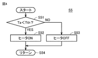
- FIG. 4 is a flowchart for explaining the energization control of the heater at the start of the liquid discharge promotion control.
- the control device 30 acquires the outside air temperature Ta from the outside air temperature sensor 8 and determines whether or not the outside air temperature Ta is lower than the first threshold temperature Tth.
- the control device 30 When Ta ⁇ Tth is established (YES in S51), the control device 30 energizes the heater 40, and the heater 40 heats the liquid refrigerant inside the compressor 1 for a delay time of 30 minutes. On the other hand, when Ta ⁇ Tth is not established (NO in S51), the control device 30 does not energize the heater 40, the heater is off for a delay time of 30 minutes, and the compressor 1 is affected by the outside air temperature. Wait for the internal liquid refrigerant to warm up.
- the stop time of the compressor 1 at the time of the fourth and subsequent start retries is set to be longer than that at the time of the first start retry.
- the liquid refrigerant in the compressor 1 can be heated by the heating by the heater 40 or the outside air temperature, and can be sufficiently expelled from the compressor 1. In this way, the amount of liquid in the compressor 1 can be reduced, and a start failure due to an overcurrent abnormality at the time of start retry can be suppressed.
- the present embodiment relates to a cold heat source unit 100 connected to a load device 110 and constituting a refrigeration cycle device 200.
- the cold heat source unit 100 includes a compressor 1 and a control device 30 for controlling the compressor 1.
- the control device 30 detects an overload of the compressor 1, it executes a first start retry control in which the compressor 1 is stopped for a first time and then the compressor 1 is restarted.
- the control device 30 stops the compressor 1 for a second time longer than the first time, and then restarts the compressor 1. 2 Execute start retry control.
- the second time is the time required for the amount of liquid in the compressor 1 to decrease and the compressor 1 to be restartable.
- the cold heat source unit 100 further includes a heater 40 configured to heat the liquid refrigerant inside the compressor 1.
- the control device 30 is configured to heat the liquid refrigerant by the heater 40 when executing the second start retry control.
- the heater 40 further promotes the vaporization of the liquid refrigerant in the compressor 1 and reduces the amount of the liquid.
- the overload at startup is eliminated, and the possibility of successfully restarting the compressor 1 is further increased.
- the control device 30 when the outside air temperature Ta does not exceed the first threshold temperature Tth, the control device 30 performs the second activation while executing the heating of the liquid refrigerant by the heater 40. Execute retry control. When the outside air temperature Ta exceeds the first threshold temperature Tth, the control device 30 executes the second start retry control with the heating of the liquid refrigerant by the heater 40 stopped.
- the control device 30 makes a first start retry when the difference between the refrigerant evaporation temperature ET and the target evaporation temperature ETm is less than the second threshold temperature (for example, 10K). Take control.
- the second threshold temperature for example, 10K
- the evaporation temperature ET becomes higher than the target evaporation temperature ETm to some extent. , It is possible to avoid a further rise in the temperature inside the refrigerator due to delaying the start-up time.
- the number of times the first start retry control is executed is the first determination value (1st determination value. Even if it exceeds (for example, 3 times), the first start retry control is executed.
- the control device 30 sucks the liquid refrigerant into the compressor 1 based on at least one of the degree of superheat of the refrigerant sucked by the compressor 1, the temperature under the shell of the compressor 1, and the degree of superheat of the refrigerant in the compressor 1. Judge the presence or absence.
- the control device 30 when the control device 30 fails to start the compressor 1 when the second start retry control is performed, the second start retry control is repeatedly executed, and the control device 30 controls the second start retry control.
- the compressor 1 When the number of times of execution exceeds the second judgment value, the compressor 1 is set to the stopped state, and the first judgment value is 60% of the total of the first judgment value and the second judgment value. It is a judgment value.
- the control device 30 is a compressor. Set 1 to the stopped state. Therefore, since the first determination value is 3 and the second determination value is 2, the first determination value is 60% of the total of the first determination value and the second determination value. Since the effect of liquid discharge can be most expected when the vehicle is stopped for a total of 60 minutes (30 minutes x 2 times), the liquid is discharged when 3 out of 5 start retries are exceeded.
Landscapes
- Engineering & Computer Science (AREA)
- Mechanical Engineering (AREA)
- General Engineering & Computer Science (AREA)
- Physics & Mathematics (AREA)
- Thermal Sciences (AREA)
- Chemical & Material Sciences (AREA)
- Combustion & Propulsion (AREA)
- Computer Hardware Design (AREA)
- Air Conditioning Control Device (AREA)
Abstract
冷熱源ユニット(100)は、圧縮機(1)と、圧縮機(1)を制御する制御装置(30)とを備える。制御装置(30)は、圧縮機(1)の過負荷を検出した場合に、圧縮機(1)を第1時間停止してから圧縮機(1)を再起動する第1起動リトライ制御を実行する。制御装置(30)は、第1起動リトライ制御を実行した回数が第1判定値を超えた場合に、圧縮機(1)を第1時間よりも長い第2時間停止してから圧縮機(1)を再起動する第2起動リトライ制御を実行する。
Description
この発明は、冷熱源ユニットおよび冷凍サイクル装置に関する。
従来、例えば冷凍装置等において、除霜後の起動時にユニット内の液冷媒が大量にアキュムレータに戻る場合がある。このとき、アキュムレータの下部に設置された油戻し回路の内部に液冷媒が大量に通流し、この液冷媒が油戻し回路から圧縮機に過剰に流れ込む液戻り現象(以下、「液バック」という)が発生する場合がある。運転時の液バックにより圧縮機内で圧力が急上昇し、圧縮機の運転電流が過電流状態となる問題があった。
特開平6-34224号公報(特許文献1)には、過電流状態に起因する圧縮機の故障を防止するために、電流値比較部により圧縮機電流値が或る値以上を或る時間継続したら圧縮機を一旦停止し、圧縮機停止後或る時間後に圧縮機の再起動を行ない、同じ動作を或る回数繰り返したら全運転停止を行なう暖冷房機が開示されている。
液バックにより圧縮機内に液冷媒が溜まった状態で圧縮機を再起動しようとした際、液圧縮運転に伴う圧縮機のモータ負荷の増大によって過電流状態となり、圧縮機が一旦停止する場合がある。特開平6-34224号公報(特許文献1)に開示された技術では、圧縮機停止後の或る時間後に圧縮機の再起動を試みる。以下、この圧縮機の再起動試行を「起動リトライ」ということとする。しかし、圧縮機内に液冷媒の残留量が多い状態で起動リトライをしても過電流のために圧縮機が停止してしまい、起動リトライを繰り返して全運転停止となる可能性が高いという課題がある。
本発明は、上記のような課題を解決するためになされたものであって、過電流によって圧縮機が停止された場合に、圧縮機の再起動の成功確率が向上した冷熱源ユニットおよび冷凍サイクル装置を提供することを目的とする。
本開示は、負荷装置に接続され冷凍サイクル装置を構成する冷熱源ユニットに関する。冷熱源ユニットは、圧縮機と、圧縮機を制御する制御装置とを備える。制御装置は、圧縮機の過負荷を検出した場合に、圧縮機を第1時間停止してから圧縮機を再起動する第1起動リトライ制御を実行する。制御装置は、第1起動リトライ制御を実行した回数が第1判定値を超えた場合に、圧縮機を第1時間よりも長い第2時間停止してから圧縮機を再起動する第2起動リトライ制御を実行する。
本発明によれば、圧縮機の起動がうまくいかない場合に、圧縮機起動までの待ち時間を長くして再起動を行なうため、圧縮機内の液冷媒が排出され、再起動の成功確率が向上する。
以下、本発明の実施の形態について、図面を参照しながら詳細に説明する。以下では、複数の実施の形態について説明するが、各実施の形態で説明された構成を適宜組み合わせることは出願当初から予定されている。なお、図中同一または相当部分には同一符号を付してその説明は繰返さない。なお、以下の図は各構成部材の大きさの関係が実際のものとは異なる場合がある。
図1は、本実施の形態における冷凍サイクル装置200の冷媒回路を表す図である。図1に示すように、冷凍サイクル装置200は、冷熱源ユニット100と、負荷装置110とを備える。なお、「冷熱源ユニット」は、「熱源ユニット」と呼ばれることもある。
負荷装置110は、膨張弁3と、第1熱交換器(以下、蒸発器4という)とを含む。冷熱源ユニット100は、負荷装置110に接続され冷凍サイクル装置200を構成する。冷熱源ユニット100は、圧縮機1と、第2熱交換器(以下、凝縮器2という)と、ヒータ40と、圧縮機1およびヒータ40を制御する制御装置30とを備える。
制御装置30は、CPU(Central Processing Unit)31と、メモリ32(ROM(Read Only Memory)およびRAM(Random Access Memory))と、各種信号を入力するための図示しない入出力装置等を含んで構成される。CPU31は、ROMに格納されているプログラムをRAM等に展開して実行する。ROMに格納されるプログラムは、制御装置30の処理手順が記されたプログラムである。制御装置30は、これらのプログラムに従って、冷熱源ユニット100における各機器の制御を実行する。この制御については、ソフトウェアによる処理に限られず、専用のハードウェア(電子回路)で処理することも可能である。
また、圧縮機1には、吸入温度を検出するサーミスタ5と、圧縮機1の筐体外郭下部の温度または圧縮機1の筐体内に滞留する冷凍機油の温度(以下、「シェル下温度」という)を検出するサーミスタ6と、過電流を検出する電流センサ7とが付随している。
冷凍サイクル装置200では、圧縮機1が冷媒ガスを圧縮して高圧のガスにし、高圧のガス冷媒が凝縮器2に流れる。凝縮器2では、冷媒から熱が放出され、高圧のガス冷媒は凝縮し、高圧の液冷媒となる。高圧の液冷媒は膨張弁3に流れる。膨張弁3にて高圧の液冷媒は減圧され、低圧の液冷媒が蒸発器4に流れる。蒸発器4において液冷媒は蒸発し、周囲の熱を奪う冷却作用が行なわれる。蒸発したガス冷媒は、圧縮機1に戻り、冷媒回路が成立する。
本実施の形態では、過負荷を検知した場合圧縮機1を停止し、停止時間を十分な時間確保することによって圧縮機1内の液量を減少させ、起動リトライ時の起動不良を抑制する。たとえば、制御装置30は、電流センサ7によって過電流が検出された場合に、圧縮機1の負荷が、過負荷であることを検知する。
具体的には、制御装置30は、圧縮機1の過負荷を検出した場合に、圧縮機1を第1時間停止してから圧縮機1を再起動する第1起動リトライ制御を実行する。そして、制御装置30は、第1起動リトライ制御を実行した回数が判定値を超えた場合に、圧縮機1を第1時間よりも長い第2時間停止してから圧縮機1を再起動する第2起動リトライ制御を実行する。停止時間については、以下に限定されないが、たとえば、第1時間を3分とし、第2時間を30分とすることができる。
図2は、圧縮機の停止時間と圧縮機内の液量変化率との関係を示した図である。図2に示す関係および圧縮機停止に伴う庫内温度上昇を考慮し、1回の液排出促進制御実施における圧縮機停止時間を決定する。
庫内が通常運転により冷却された状態で、圧縮機を停止した場合、庫内温度の上昇が許容されるのは、60分程度である。ただし、60分よりも前に、圧縮機1の起動時に過電流が生じない程度に液量が減少していれば、停止時間は短い方がよい。したがって、本実施の形態では、液排出促進制御を2回まで実施することとし、1回の液排出促進制御実施における圧縮機停止時間を30分と設定する。
図3は、圧縮機の起動リトライを実行する制御を説明するためのフローチャートである。このフローチャートにより過電流異常の起動不良の改善について説明する。
まずステップS1において、制御装置30は、過電流による起動リトライ制御を5回実施したか否かを判断する。
起動リトライ制御の回数の合計が5回に達していれば(S1でYES)、制御装置30は、ステップS10に処理をすすめ、これ以上の起動リトライ制御を実行しないようにし、異常停止であることを報知する。たとえば、発光ダイオードの点灯などによってユーザに異常停止したことが認識可能とされる。
起動リトライ制御の回数の合計が5回に達していなければ(S1でNO)、制御装置30は、ステップS2において、起動リトライ制御の回数の合計が3回に達しているか否かを判断する。
起動リトライ制御の回数の合計が3回に達していなければ(S2でNO)、制御装置30は、ステップS11に処理をすすめ、圧縮機の通常の起動リトライ制御を行なう。たとえば、この場合には、3分間圧縮機を停止させた状態に維持した後に、圧縮機1に通電し、再起動を試みる。この3分間は、圧縮機1の液冷媒量が少ない状態において発停を繰り返さないよう定めた時間である。
一方、起動リトライ制御の回数の合計が3回に達した場合(S2でYES)、制御装置30は、ステップS3に処理をすすめる。
原則的には、ステップS2でYESと判定された場合には、圧縮機1の起動を今までよりも遅延させるステップS5以降の制御を実行する。ただし、圧縮機1の長時間停止に伴う不冷の不具合を防止するため、あるいはその他の重要度の高い制御を優先させるため、ステップS5以降の処理を実施せずに今まで通りの圧縮機1の起動を5回まで繰り返す場合もある。たとえば、以下のような場合が想定される。
・除霜運転などによって庫内温度があるしきい値以上となった場合、冷熱源ユニットの冷凍能力が不足している場合など、冷却を優先する必要がある場合。
・液バックが発生していない場合。
・圧縮機1の冷凍機油が不足し、油戻し制御が開始された場合。
・圧縮機1の吐出側と吸入側の圧力が逆転するおそれがある場合。
・低圧圧力センサがオープンあるいはショートを検知し、異常となった場合。
・除霜運転などによって庫内温度があるしきい値以上となった場合、冷熱源ユニットの冷凍能力が不足している場合など、冷却を優先する必要がある場合。
・液バックが発生していない場合。
・圧縮機1の冷凍機油が不足し、油戻し制御が開始された場合。
・圧縮機1の吐出側と吸入側の圧力が逆転するおそれがある場合。
・低圧圧力センサがオープンあるいはショートを検知し、異常となった場合。
これらの判定をすべて行なっても良い。しかし、本実施の形態では、ステップS5の処理に移行する前に、ステップS3,S4における判定が行なわれる。
ステップS3では、制御装置30は、サーミスタ5およびサーミスタ6で温度測定し、吸入冷媒の過熱度(吸入SH)、シェル下温度、および圧縮機1の筐体内に滞留する冷凍機油の過熱度(以下、シェル下SHという)のいずれか1つが、各々に対応する基準値よりも一定時間(たとえば3分間)低下した状態が継続しているか否かを判断する。これにより、制御装置30は、液バックの発生の有無を判断する。
ただし、過熱度(SH:スーパーヒート)は、実際に計測した冷媒温度と計測した圧力に対応する飽和ガス温度の温度差である。
制御装置30は、たとえば、3分連続で吸入SHが目標値よりも10K低下した場合に、液バックが発生したことを検出する。
吸入SH、シェル下温度、およびシェル下SHのいずれも基準値よりも一定時間低下した状態が継続していない場合(S3でNO)、ステップS12において制御装置30は、圧縮機の通常の起動リトライ制御を行なう。たとえば、この場合には、3分間圧縮機を停止させた状態に維持した後に、圧縮機1に通電し、再起動を試みる。
一方、吸入SH、シェル下温度、およびシェル下SHのいずれかが基準値よりも一定時間低下した状態が継続している場合(S3でYES)、制御装置30は、ステップS4に処理を進める。
ステップS4では、制御装置30は、蒸発温度ETが目標蒸発温度ETm+10K(ケルビン)より低いか否かを判断する。蒸発温度ETと目標蒸発温度ETmの差が10K以下であれば、圧縮機をある程度の時間停止させても庫内の冷却を保つことができると判断できる。なお、蒸発温度ETは、蒸発器4に温度センサを設けて測定しても良いが、吸入温度を検出するサーミスタ5の検出温度で代用しても良い。
ET<ETm+10Kが成立しない場合(S4でNO)、ステップS13において制御装置30は、圧縮機の通常の起動リトライ制御を行なう。たとえば、この場合には、3分間圧縮機を停止させた状態に維持した後に、圧縮機1に通電し、再起動を試みる。たとえば、除霜運転後の庫内温度が高い場合、または複数台の負荷ユニットが接続されており冷熱源ユニットの冷凍能力が不足して庫内温度が高い場合には、30分間の停止時間は長すぎるからである。
ET<ETm+10Kが成立する場合(S4でYES)、ステップS5において制御装置30は、圧縮機1の起動を遅延させる液排出促進制御を開始する。そして、圧縮機1を停止してからの時間の計測が開始される。このような圧縮機1を停止してから再起動するまでの計測中の時間を「遅延時間」ということにする。制御装置30は、圧縮機1中の液冷媒を十分に減少させるために、遅延時間が第2時間(たとえば、30分間)に至るまでの間は、圧縮機1を停止したままにする。この第2時間は、ステップS11,S12,S13における停止時間である第1時間(たとえば、3分間)よりも長く設定される。このとき液排出促進制御の実施状況をユーザが判定するため、冷凍装置に搭載の制御基板の液晶ディスプレイに“Lout”等の表示することが好ましい。
まずステップS6において、遅延時間が設定時間(たとえば、30分間)経過したか否かが判断される。遅延時間が設定時間経過した場合(S6でYES)、ステップS14において、圧縮機1の起動リトライが実行される。
一方、遅延時間が設定時間経過していない場合(S6でNO)、ステップS7に処理が進められる。ステップS7では、油戻し制御の開始要求があるか否かが判断される。なお、油戻し制御は、圧縮機1の焼き付きが生じるのを防ぐために、圧縮機1内の冷凍機油が不足したときに要求が発生する。
油戻し制御の開始要求がある場合(S7でYES)、ステップS15において、圧縮機1の起動リトライが実行される。
一方、油戻し制御の開始要求がない場合(S7でNO)、ステップS8に処理が進められる。ステップS8では、高低圧逆転防止制御の開始要求があるか否かが判断される。なお、高低圧逆転防止制御は、圧縮機1の吸入ポート側圧力が吐出ポート側圧力よりも高いことが検出された場合に開始要求が発生する。
高低圧逆転防止制御の開始要求がある場合(S8でYES)、ステップS16において、圧縮機1の起動リトライが実行される。
一方、高低圧逆転防止制御の開始要求がない場合(S8でNO)、ステップS9に処理が進められる。ステップS9では、蒸発温度ETが3分間連続して目標蒸発温度ETm+10K(ケルビン)以上となっているか否かが判断される。
Et≧ETm+10Kである状態が3分連続した場合には(S9でYES)、庫内の温度上昇を許容できないので、ステップS17において、圧縮機1の起動リトライが実行される。ただし、瞬間的に蒸発温度Etがしきい値を超える可能性があるため、ここでは3分連続を起動遅延中断の条件としている。
目標蒸発温度ETm+10K(ケルビン)以上となっている時間が3分間未満である場合には(S9でNO)、ステップS6に処理が戻され、圧縮機の起動リトライ開始までの遅延時間の計測が続行される。
ステップS11~S17のいずれかにおいて、圧縮機1の起動リトライが実施された場合、ステップS18において、制御装置30は、圧縮機1の起動が正常に完了したか否かを判断する。
たとえば、過電流が再び検出された場合には、圧縮機1の起動は失敗と判断され(S18でNO)、圧縮機1のモータへの通電が遮断され、圧縮機1は停止される。この場合には、制御装置30は、ステップS19において、起動リトライ回数を1増加させ、再びステップS1から処理を実行する。
そして、液冷媒流出促進制御を2回実施した後に起動リトライしても圧縮機が起動しない場合はステップS10において運転停止させる。このときには、過電流異常検知の原因が液バックによるものでないと判断できる。
一方、過電流が検出されていない場合には、圧縮機1の起動は成功と判断され(S18でYES)、ステップS20において、起動リトライ回数のカウントが初期化され、ステップS21において、通常の圧縮機1の通常運転状態の制御ルーチンに処理が戻される。
なお、ステップS5における液排出促進制御の開始時には、ヒータ40を併用して加熱しても良いが、外気温が高い場合には、省エネルギのためにヒータ40を停止してもよい。
図4は、液排出促進制御開始時のヒータの通電制御を説明するためのフローチャートである。図4を参照して、ステップS51において制御装置30は、外気温センサ8から外気温Taを取得し、外気温Taが第1しきい値温度Tthよりも低いか否かを判断する。
Ta<Tthが成立した場合には(S51でYES)、制御装置30は、ヒータ40に通電し、30分の遅延時間の間、ヒータ40によって圧縮機1の内部の液冷媒を加熱する。一方、Ta<Tthが成立しない場合には(S51でNO)、制御装置30は、ヒータ40への通電は行なわず、30分の遅延時間においてヒータOFFの状態で、外気温によって圧縮機1の内部の液冷媒が温められるのを待つ。
このように、外気温に応じてヒータ加熱を実行するか否かを変更するようにすれば、必要以上の冷媒の加熱が行なわれないので、消費電力を低減させることができる。
以上説明したように、本実施の形態の冷凍サイクル装置によれば、4回目以降の起動リトライ時の圧縮機1の停止時間を初回起動リトライ時よりも長い時間にする。これによって、液バックにより圧縮機1内の液量が増加した状態においても、ヒータ40による加熱または外気温度により圧縮機1内の液冷媒を加熱し、圧縮機1から十分に追い出すことができる。このようにして圧縮機1内の液量を減少させ、起動リトライ時の過電流異常による起動不良を抑制することができる。
最後に、本実施の形態について、再び図面を参照して総括する。
図1を参照して、本実施の形態は、負荷装置110に接続され冷凍サイクル装置200を構成する冷熱源ユニット100に関する。冷熱源ユニット100は、圧縮機1と、圧縮機1を制御する制御装置30とを備える。制御装置30は、圧縮機1の過負荷を検出した場合に、圧縮機1を第1時間停止してから圧縮機1を再起動する第1起動リトライ制御を実行する。制御装置30は、第1起動リトライ制御を実行した回数が第1判定値を超えた場合に、圧縮機1を第1時間よりも長い第2時間停止してから圧縮機1を再起動する第2起動リトライ制御を実行する。
図1を参照して、本実施の形態は、負荷装置110に接続され冷凍サイクル装置200を構成する冷熱源ユニット100に関する。冷熱源ユニット100は、圧縮機1と、圧縮機1を制御する制御装置30とを備える。制御装置30は、圧縮機1の過負荷を検出した場合に、圧縮機1を第1時間停止してから圧縮機1を再起動する第1起動リトライ制御を実行する。制御装置30は、第1起動リトライ制御を実行した回数が第1判定値を超えた場合に、圧縮機1を第1時間よりも長い第2時間停止してから圧縮機1を再起動する第2起動リトライ制御を実行する。
好ましくは、第2時間は、圧縮機1内の液量が減少し、圧縮機1が再起動可能となるのに必要な時間である。
これにより、第2起動リトライ制御では、圧縮機1の内部の液冷媒の量が第1起動リトライ制御実行時よりも減少していることが期待されるため、圧縮機1の過負荷が解消され、圧縮機1の再起動が成功する可能性が高まる。
好ましくは、冷熱源ユニット100は、圧縮機1の内部の液冷媒を加熱するように構成されたヒータ40をさらに備える。制御装置30は、第2起動リトライ制御を実行する場合に、ヒータ40によって、液冷媒を加熱するように構成される。
このようにすることによって、第2起動リトライ制御を実行する際に、ヒータ40によって圧縮機1中の液冷媒の気化が一層促進され液量が減少することが期待されるため、圧縮機1の起動時の過負荷が解消され、圧縮機1の再起動が成功する可能性がさらに高まる。
より好ましくは、図4に示すように、制御装置30は、外気温Taが第1しきい値温度Tthを超えていない場合には、ヒータ40による液冷媒の加熱を実行しながら、第2起動リトライ制御を実行する。制御装置30は、外気温Taが第1しきい値温度Tthを超えていると場合には、ヒータ40による液冷媒の加熱を停止した状態で、第2起動リトライ制御を実行する。
このようにすることによって、外気温Taが高く、ヒータ40による加熱を行なわなくても第2時間の待ち時間内に圧縮機1の液冷媒量が減少する場合には、ヒータ40に通電しないので消費電力を低減させることができる。
好ましくは、図3のステップS4に示すように、制御装置30は、冷媒の蒸発温度ETと目標蒸発温度ETmの差が第2しきい値温度(たとえば10K)を下回る場合に、第1起動リトライ制御を実行する。
このようにすることによって、除霜運転後の庫内温度が高い状況、または、冷熱源機の冷凍能力が不足する状況において、蒸発温度ETが目標蒸発温度ETmよりもある程度高くなってしまう場合に、起動時間を遅延させることによる庫内温度のさらなる上昇を避けることができる。
好ましくは、図3のステップS3に示すように、制御装置30は、圧縮機1に液冷媒の吸入が発生していない場合には、第1起動リトライ制御を実行した回数が第1判定値(たとえば3回)を超えた場合であっても第1起動リトライ制御を実行する。制御装置30は、圧縮機1が吸入する冷媒の過熱度、圧縮機1のシェル下温度、圧縮機1内の冷媒の過熱度の少なくともいずれかに基づいて圧縮機1への液冷媒の吸入の有無を判断する。
液バックが生じていない場合には圧縮機1の起動を遅延させても過負荷が解消しないので、このようにすることによって、圧縮機1の起動を遅延させることによる庫内温度の上昇を避けることができる。
好ましくは、制御装置30は、第2起動リトライ制御を行なった場合に圧縮機1の起動に失敗した場合には、第2起動リトライ制御を繰り返し実行し、制御装置30は、第2起動リトライ制御を実行した回数が第2判定値を超えた場合には、圧縮機1を停止状態に設定し、第1判定値は、第1判定値と第2判定値の合計に対して、60%となる判定値である。
具体的には、図3のフローチャートでは、3回の第1リトライ制御が行なわれた後に、2回のリトライ制御が行なわれ、それでも圧縮機1の起動が成功しない場合に制御装置30は圧縮機1を停止状態に設定する。したがって、第1判定値は3であり、第2判定値は2であるので、第1判定値は、第1判定値と第2判定値の合計に対して、60%となる。液排出の効果が最も期待できるのが、合計60分(30分×2回)停止した場合でるため、起動リトライ5回のうち3回を超えたときに液排出を実行する。
今回開示された実施の形態は、すべての点で例示であって制限的なものではないと考えられるべきである。本発明の範囲は、上記した実施の形態の説明ではなくて請求の範囲によって示され、請求の範囲と均等の意味および範囲内でのすべての変更が含まれることが意図される。
1 圧縮機、2 凝縮器、3 膨張弁、4 蒸発器、5,6 サーミスタ、7 電流センサ、8 外気温センサ、30 制御装置、31 CPU、32 メモリ、40 ヒータ、100 冷熱源ユニット、110 負荷装置、200 冷凍サイクル装置。
Claims (8)
- 負荷装置に接続され冷凍サイクル装置を構成する冷熱源ユニットであって、
圧縮機と、
前記圧縮機を制御する制御装置とを備え、
前記制御装置は、前記圧縮機の過負荷を検出した場合に、前記圧縮機を第1時間停止してから前記圧縮機を再起動する第1起動リトライ制御を実行し、
前記制御装置は、前記第1起動リトライ制御を実行した回数が第1判定値を超えた場合に、前記圧縮機を前記第1時間よりも長い第2時間停止してから前記圧縮機を再起動する第2起動リトライ制御を実行するように構成される、冷熱源ユニット。 - 前記圧縮機の内部の液冷媒を加熱するように構成された加熱装置をさらに備え、
前記制御装置は、前記第2起動リトライ制御を実行する場合に、前記加熱装置によって、前記液冷媒を加熱するように構成される、請求項1に記載の冷熱源ユニット。 - 前記制御装置は、外気温が第1しきい値温度を超えていない場合には、前記加熱装置による前記液冷媒の加熱を実行しながら、前記第2起動リトライ制御を実行し、
前記制御装置は、前記外気温が前記第1しきい値温度を超えていると場合には、前記加熱装置による前記液冷媒の加熱を停止した状態で、前記第2起動リトライ制御を実行する、請求項2に記載の冷熱源ユニット。 - 前記制御装置は、冷媒の蒸発温度と目標蒸発温度の差が第2しきい値温度を下回る場合に、前記第1起動リトライ制御を実行する、請求項1~3のいずれか1項に記載の冷熱源ユニット。
- 前記制御装置は、前記圧縮機に液冷媒の吸入が発生していない場合には、前記第1起動リトライ制御を実行した回数が前記第1判定値を超えた場合であっても前記第1起動リトライ制御を実行し、
前記制御装置は、前記圧縮機が吸入する冷媒の過熱度、前記圧縮機のシェル下温度、前記圧縮機内の冷媒の過熱度の少なくともいずれかに基づいて前記圧縮機への前記液冷媒の吸入の有無を判断する、請求項1に記載の冷熱源ユニット。 - 前記第2時間は、前記圧縮機内の液量が減少し、前記圧縮機が再起動可能となるのに必要な時間である、請求項1~5のいずれか1項に記載の冷熱源ユニット。
- 前記制御装置は、前記第2起動リトライ制御を行なった場合に前記圧縮機の起動に失敗した場合には、前記第2起動リトライ制御を繰り返し実行し、
前記制御装置は、前記第2起動リトライ制御を実行した回数が第2判定値を超えた場合には、前記圧縮機を停止状態に設定し、
前記第1判定値は、前記第1判定値と前記第2判定値の合計に対して、60%となる判定値である、請求項1~5のいずれか1項に記載の冷熱源ユニット。 - 請求項1~7のいずれか1項に記載の冷熱源ユニットと、前記負荷装置とを備える冷凍サイクル装置。
Priority Applications (4)
| Application Number | Priority Date | Filing Date | Title |
|---|---|---|---|
| PCT/JP2019/044891 WO2021095237A1 (ja) | 2019-11-15 | 2019-11-15 | 冷熱源ユニットおよび冷凍サイクル装置 |
| CN201980102102.5A CN114729765B (zh) | 2019-11-15 | 2019-11-15 | 冷热源单元以及制冷循环装置 |
| EP19952629.4A EP4060250B1 (en) | 2019-11-15 | 2019-11-15 | Cold heat source unit and refrigeration circuit device |
| JP2021555751A JP7399182B2 (ja) | 2019-11-15 | 2019-11-15 | 冷熱源ユニットおよび冷凍サイクル装置 |
Applications Claiming Priority (1)
| Application Number | Priority Date | Filing Date | Title |
|---|---|---|---|
| PCT/JP2019/044891 WO2021095237A1 (ja) | 2019-11-15 | 2019-11-15 | 冷熱源ユニットおよび冷凍サイクル装置 |
Publications (1)
| Publication Number | Publication Date |
|---|---|
| WO2021095237A1 true WO2021095237A1 (ja) | 2021-05-20 |
Family
ID=75911485
Family Applications (1)
| Application Number | Title | Priority Date | Filing Date |
|---|---|---|---|
| PCT/JP2019/044891 WO2021095237A1 (ja) | 2019-11-15 | 2019-11-15 | 冷熱源ユニットおよび冷凍サイクル装置 |
Country Status (4)
| Country | Link |
|---|---|
| EP (1) | EP4060250B1 (ja) |
| JP (1) | JP7399182B2 (ja) |
| CN (1) | CN114729765B (ja) |
| WO (1) | WO2021095237A1 (ja) |
Cited By (2)
| Publication number | Priority date | Publication date | Assignee | Title |
|---|---|---|---|---|
| CN113418327A (zh) * | 2021-05-28 | 2021-09-21 | 青岛海尔空调电子有限公司 | 冷藏冷冻机组的回油控制方法及冷藏冷冻机组 |
| CN113432343A (zh) * | 2021-05-28 | 2021-09-24 | 青岛海尔空调电子有限公司 | 冷藏冷冻机组的回油控制方法及冷藏冷冻机组 |
Citations (6)
| Publication number | Priority date | Publication date | Assignee | Title |
|---|---|---|---|---|
| JPH0493558A (ja) * | 1990-08-06 | 1992-03-26 | Daikin Ind Ltd | 冷凍装置の運転制御装置 |
| JPH0634224A (ja) | 1992-07-17 | 1994-02-08 | Matsushita Electric Ind Co Ltd | 暖冷房機 |
| JPH08261571A (ja) * | 1995-03-20 | 1996-10-11 | Matsushita Electric Ind Co Ltd | 圧縮式冷凍装置の起動方法 |
| JPH09149547A (ja) * | 1995-11-24 | 1997-06-06 | Matsushita Electric Ind Co Ltd | 空気調和機の運転制御装置と運転制御方法 |
| JP2000105011A (ja) * | 1998-09-30 | 2000-04-11 | Daikin Ind Ltd | 二元冷凍装置 |
| JP2009216000A (ja) * | 2008-03-11 | 2009-09-24 | Hitachi Industrial Equipment Systems Co Ltd | インバータ圧縮機の制御方法及びインバータ圧縮機 |
Family Cites Families (14)
| Publication number | Priority date | Publication date | Assignee | Title |
|---|---|---|---|---|
| JPH06123514A (ja) * | 1992-10-12 | 1994-05-06 | Matsushita Electric Ind Co Ltd | 暖冷房機 |
| JPH10205895A (ja) * | 1997-01-28 | 1998-08-04 | Matsushita Refrig Co Ltd | 冷凍サイクル制御装置 |
| JPH11108471A (ja) * | 1997-10-02 | 1999-04-23 | Mitsubishi Heavy Ind Ltd | 空気調和機 |
| JP4327936B2 (ja) | 1999-04-08 | 2009-09-09 | 三菱電機株式会社 | ヒートポンプ式冷凍装置 |
| US6119469A (en) * | 1999-06-14 | 2000-09-19 | Spx Corporation | Programmable electronic start-up delay for refrigeration units |
| US6578373B1 (en) * | 2000-09-21 | 2003-06-17 | William J. Barbier | Rate of change detector for refrigerant floodback |
| KR100484800B1 (ko) * | 2002-06-19 | 2005-04-22 | 엘지전자 주식회사 | 공기조화기의 압축기 동작방법 |
| JP4273492B2 (ja) | 2003-12-18 | 2009-06-03 | 三菱電機株式会社 | 空気調和装置及び冷凍装置 |
| JP5558132B2 (ja) * | 2010-02-16 | 2014-07-23 | 三菱電機株式会社 | 冷凍機及びこの冷凍機が接続された冷凍装置 |
| JP5342528B2 (ja) * | 2010-09-25 | 2013-11-13 | 日立アプライアンス株式会社 | アクティブフィルタを備えた空気調和装置 |
| JP6440930B2 (ja) | 2013-06-20 | 2018-12-19 | 三菱重工サーマルシステムズ株式会社 | 空気調和機及び空気調和機の制御方法 |
| CN108369046B (zh) * | 2015-12-11 | 2020-07-28 | 三菱电机株式会社 | 制冷循环装置 |
| WO2018073855A1 (ja) | 2016-10-17 | 2018-04-26 | 三菱電機株式会社 | 空気調和機 |
| CN110192070A (zh) * | 2017-01-25 | 2019-08-30 | 三菱电机株式会社 | 制冷循环装置 |
-
2019
- 2019-11-15 JP JP2021555751A patent/JP7399182B2/ja active Active
- 2019-11-15 WO PCT/JP2019/044891 patent/WO2021095237A1/ja unknown
- 2019-11-15 EP EP19952629.4A patent/EP4060250B1/en active Active
- 2019-11-15 CN CN201980102102.5A patent/CN114729765B/zh active Active
Patent Citations (6)
| Publication number | Priority date | Publication date | Assignee | Title |
|---|---|---|---|---|
| JPH0493558A (ja) * | 1990-08-06 | 1992-03-26 | Daikin Ind Ltd | 冷凍装置の運転制御装置 |
| JPH0634224A (ja) | 1992-07-17 | 1994-02-08 | Matsushita Electric Ind Co Ltd | 暖冷房機 |
| JPH08261571A (ja) * | 1995-03-20 | 1996-10-11 | Matsushita Electric Ind Co Ltd | 圧縮式冷凍装置の起動方法 |
| JPH09149547A (ja) * | 1995-11-24 | 1997-06-06 | Matsushita Electric Ind Co Ltd | 空気調和機の運転制御装置と運転制御方法 |
| JP2000105011A (ja) * | 1998-09-30 | 2000-04-11 | Daikin Ind Ltd | 二元冷凍装置 |
| JP2009216000A (ja) * | 2008-03-11 | 2009-09-24 | Hitachi Industrial Equipment Systems Co Ltd | インバータ圧縮機の制御方法及びインバータ圧縮機 |
Non-Patent Citations (1)
| Title |
|---|
| See also references of EP4060250A4 |
Cited By (4)
| Publication number | Priority date | Publication date | Assignee | Title |
|---|---|---|---|---|
| CN113418327A (zh) * | 2021-05-28 | 2021-09-21 | 青岛海尔空调电子有限公司 | 冷藏冷冻机组的回油控制方法及冷藏冷冻机组 |
| CN113432343A (zh) * | 2021-05-28 | 2021-09-24 | 青岛海尔空调电子有限公司 | 冷藏冷冻机组的回油控制方法及冷藏冷冻机组 |
| CN113432343B (zh) * | 2021-05-28 | 2023-02-03 | 青岛海尔空调电子有限公司 | 冷藏冷冻机组的回油控制方法及冷藏冷冻机组 |
| CN113418327B (zh) * | 2021-05-28 | 2023-02-28 | 青岛海尔空调电子有限公司 | 冷藏冷冻机组的回油控制方法及冷藏冷冻机组 |
Also Published As
| Publication number | Publication date |
|---|---|
| JP7399182B2 (ja) | 2023-12-15 |
| EP4060250A4 (en) | 2022-10-26 |
| CN114729765A (zh) | 2022-07-08 |
| EP4060250B1 (en) | 2024-02-28 |
| EP4060250A1 (en) | 2022-09-21 |
| CN114729765B (zh) | 2024-05-17 |
| JPWO2021095237A1 (ja) | 2021-05-20 |
Similar Documents
| Publication | Publication Date | Title |
|---|---|---|
| US9719709B2 (en) | Air-conditioning apparatus with thermo-off postponement control | |
| EP1953477A1 (en) | Refrigerator compressor operating method and refrigerator | |
| DK201870232A1 (en) | Refrigeration cycle device | |
| JP5641875B2 (ja) | 冷凍装置 | |
| WO2021095237A1 (ja) | 冷熱源ユニットおよび冷凍サイクル装置 | |
| KR101275184B1 (ko) | 냉동시스템의 제어방법 | |
| US8418498B2 (en) | Refrigeration device and method for controlling a refrigeration device | |
| JP2000320936A (ja) | 冷凍サイクルの安全装置 | |
| JP2500522B2 (ja) | 冷凍装置の運転制御装置 | |
| JP2011169475A (ja) | 冷凍機及びこの冷凍機が接続された冷凍装置 | |
| JPH09236336A (ja) | 空気調和機の運転制御装置 | |
| WO2022059149A1 (ja) | 冷凍サイクル装置及びそれを備える空気調和機、並びに冷凍サイクル装置の制御方法 | |
| KR101097976B1 (ko) | 냉장고 운전 제어방법 | |
| JPH10185334A (ja) | 冷凍装置 | |
| JP2004019950A (ja) | 冷蔵庫 | |
| JP5498932B2 (ja) | 制御装置及び熱源機システム | |
| JP3219040B2 (ja) | 冷凍装置 | |
| WO2022168238A1 (ja) | 冷熱源ユニットおよび冷凍サイクル装置 | |
| JPH05288386A (ja) | 空気調和装置の室外ファンの運転制御装置 | |
| JP2008057835A (ja) | 冷凍装置 | |
| JP2927230B2 (ja) | 二元冷凍装置 | |
| JP2022177977A (ja) | 熱媒体循環型加熱ヒートポンプ装置 | |
| KR100568517B1 (ko) | 냉장고의 제어방법 | |
| JP2015175575A (ja) | 冷凍装置 | |
| JP4326274B2 (ja) | 冷凍回路 |
Legal Events
| Date | Code | Title | Description |
|---|---|---|---|
| 121 | Ep: the epo has been informed by wipo that ep was designated in this application |
Ref document number: 19952629 Country of ref document: EP Kind code of ref document: A1 |
|
| ENP | Entry into the national phase |
Ref document number: 2021555751 Country of ref document: JP Kind code of ref document: A |
|
| NENP | Non-entry into the national phase |
Ref country code: DE |
|
| ENP | Entry into the national phase |
Ref document number: 2019952629 Country of ref document: EP Effective date: 20220615 |