EP4060250B1 - Cold heat source unit and refrigeration circuit device - Google Patents
Cold heat source unit and refrigeration circuit device Download PDFInfo
- Publication number
- EP4060250B1 EP4060250B1 EP19952629.4A EP19952629A EP4060250B1 EP 4060250 B1 EP4060250 B1 EP 4060250B1 EP 19952629 A EP19952629 A EP 19952629A EP 4060250 B1 EP4060250 B1 EP 4060250B1
- Authority
- EP
- European Patent Office
- Prior art keywords
- compressor
- controller
- source unit
- retry control
- cold source
- Prior art date
- Legal status (The legal status is an assumption and is not a legal conclusion. Google has not performed a legal analysis and makes no representation as to the accuracy of the status listed.)
- Active
Links
- 238000005057 refrigeration Methods 0.000 title claims description 21
- 239000007788 liquid Substances 0.000 claims description 60
- 239000003507 refrigerant Substances 0.000 claims description 47
- 238000001704 evaporation Methods 0.000 claims description 16
- 230000008020 evaporation Effects 0.000 claims description 16
- 238000010438 heat treatment Methods 0.000 claims description 9
- 238000000034 method Methods 0.000 description 10
- 230000005856 abnormality Effects 0.000 description 5
- 230000002265 prevention Effects 0.000 description 4
- 238000010257 thawing Methods 0.000 description 4
- 238000001816 cooling Methods 0.000 description 2
- 230000003111 delayed effect Effects 0.000 description 2
- 230000000694 effects Effects 0.000 description 2
- 230000007257 malfunction Effects 0.000 description 2
- 238000005259 measurement Methods 0.000 description 2
- 230000001419 dependent effect Effects 0.000 description 1
- 238000001514 detection method Methods 0.000 description 1
- 239000004973 liquid crystal related substance Substances 0.000 description 1
- 230000004044 response Effects 0.000 description 1
- 229920006395 saturated elastomer Polymers 0.000 description 1
Images


Classifications
-
- F—MECHANICAL ENGINEERING; LIGHTING; HEATING; WEAPONS; BLASTING
- F25—REFRIGERATION OR COOLING; COMBINED HEATING AND REFRIGERATION SYSTEMS; HEAT PUMP SYSTEMS; MANUFACTURE OR STORAGE OF ICE; LIQUEFACTION SOLIDIFICATION OF GASES
- F25B—REFRIGERATION MACHINES, PLANTS OR SYSTEMS; COMBINED HEATING AND REFRIGERATION SYSTEMS; HEAT PUMP SYSTEMS
- F25B49/00—Arrangement or mounting of control or safety devices
- F25B49/005—Arrangement or mounting of control or safety devices of safety devices
-
- F—MECHANICAL ENGINEERING; LIGHTING; HEATING; WEAPONS; BLASTING
- F04—POSITIVE - DISPLACEMENT MACHINES FOR LIQUIDS; PUMPS FOR LIQUIDS OR ELASTIC FLUIDS
- F04B—POSITIVE-DISPLACEMENT MACHINES FOR LIQUIDS; PUMPS
- F04B49/00—Control, e.g. of pump delivery, or pump pressure of, or safety measures for, machines, pumps, or pumping installations, not otherwise provided for, or of interest apart from, groups F04B1/00 - F04B47/00
- F04B49/02—Stopping, starting, unloading or idling control
-
- F—MECHANICAL ENGINEERING; LIGHTING; HEATING; WEAPONS; BLASTING
- F04—POSITIVE - DISPLACEMENT MACHINES FOR LIQUIDS; PUMPS FOR LIQUIDS OR ELASTIC FLUIDS
- F04B—POSITIVE-DISPLACEMENT MACHINES FOR LIQUIDS; PUMPS
- F04B49/00—Control, e.g. of pump delivery, or pump pressure of, or safety measures for, machines, pumps, or pumping installations, not otherwise provided for, or of interest apart from, groups F04B1/00 - F04B47/00
- F04B49/06—Control using electricity
- F04B49/065—Control using electricity and making use of computers
-
- F—MECHANICAL ENGINEERING; LIGHTING; HEATING; WEAPONS; BLASTING
- F24—HEATING; RANGES; VENTILATING
- F24F—AIR-CONDITIONING; AIR-HUMIDIFICATION; VENTILATION; USE OF AIR CURRENTS FOR SCREENING
- F24F11/00—Control or safety arrangements
- F24F11/30—Control or safety arrangements for purposes related to the operation of the system, e.g. for safety or monitoring
- F24F11/32—Responding to malfunctions or emergencies
- F24F11/37—Resuming operation, e.g. after power outages; Emergency starting
-
- F—MECHANICAL ENGINEERING; LIGHTING; HEATING; WEAPONS; BLASTING
- F25—REFRIGERATION OR COOLING; COMBINED HEATING AND REFRIGERATION SYSTEMS; HEAT PUMP SYSTEMS; MANUFACTURE OR STORAGE OF ICE; LIQUEFACTION SOLIDIFICATION OF GASES
- F25B—REFRIGERATION MACHINES, PLANTS OR SYSTEMS; COMBINED HEATING AND REFRIGERATION SYSTEMS; HEAT PUMP SYSTEMS
- F25B49/00—Arrangement or mounting of control or safety devices
- F25B49/02—Arrangement or mounting of control or safety devices for compression type machines, plants or systems
-
- F—MECHANICAL ENGINEERING; LIGHTING; HEATING; WEAPONS; BLASTING
- F04—POSITIVE - DISPLACEMENT MACHINES FOR LIQUIDS; PUMPS FOR LIQUIDS OR ELASTIC FLUIDS
- F04C—ROTARY-PISTON, OR OSCILLATING-PISTON, POSITIVE-DISPLACEMENT MACHINES FOR LIQUIDS; ROTARY-PISTON, OR OSCILLATING-PISTON, POSITIVE-DISPLACEMENT PUMPS
- F04C28/00—Control of, monitoring of, or safety arrangements for, pumps or pumping installations specially adapted for elastic fluids
- F04C28/06—Control of, monitoring of, or safety arrangements for, pumps or pumping installations specially adapted for elastic fluids specially adapted for stopping, starting, idling or no-load operation
-
- F—MECHANICAL ENGINEERING; LIGHTING; HEATING; WEAPONS; BLASTING
- F04—POSITIVE - DISPLACEMENT MACHINES FOR LIQUIDS; PUMPS FOR LIQUIDS OR ELASTIC FLUIDS
- F04C—ROTARY-PISTON, OR OSCILLATING-PISTON, POSITIVE-DISPLACEMENT MACHINES FOR LIQUIDS; ROTARY-PISTON, OR OSCILLATING-PISTON, POSITIVE-DISPLACEMENT PUMPS
- F04C28/00—Control of, monitoring of, or safety arrangements for, pumps or pumping installations specially adapted for elastic fluids
- F04C28/28—Safety arrangements; Monitoring
-
- F—MECHANICAL ENGINEERING; LIGHTING; HEATING; WEAPONS; BLASTING
- F24—HEATING; RANGES; VENTILATING
- F24F—AIR-CONDITIONING; AIR-HUMIDIFICATION; VENTILATION; USE OF AIR CURRENTS FOR SCREENING
- F24F2140/00—Control inputs relating to system states
- F24F2140/50—Load
-
- F—MECHANICAL ENGINEERING; LIGHTING; HEATING; WEAPONS; BLASTING
- F25—REFRIGERATION OR COOLING; COMBINED HEATING AND REFRIGERATION SYSTEMS; HEAT PUMP SYSTEMS; MANUFACTURE OR STORAGE OF ICE; LIQUEFACTION SOLIDIFICATION OF GASES
- F25B—REFRIGERATION MACHINES, PLANTS OR SYSTEMS; COMBINED HEATING AND REFRIGERATION SYSTEMS; HEAT PUMP SYSTEMS
- F25B2500/00—Problems to be solved
- F25B2500/26—Problems to be solved characterised by the startup of the refrigeration cycle
-
- F—MECHANICAL ENGINEERING; LIGHTING; HEATING; WEAPONS; BLASTING
- F25—REFRIGERATION OR COOLING; COMBINED HEATING AND REFRIGERATION SYSTEMS; HEAT PUMP SYSTEMS; MANUFACTURE OR STORAGE OF ICE; LIQUEFACTION SOLIDIFICATION OF GASES
- F25B—REFRIGERATION MACHINES, PLANTS OR SYSTEMS; COMBINED HEATING AND REFRIGERATION SYSTEMS; HEAT PUMP SYSTEMS
- F25B2500/00—Problems to be solved
- F25B2500/28—Means for preventing liquid refrigerant entering into the compressor
-
- F—MECHANICAL ENGINEERING; LIGHTING; HEATING; WEAPONS; BLASTING
- F25—REFRIGERATION OR COOLING; COMBINED HEATING AND REFRIGERATION SYSTEMS; HEAT PUMP SYSTEMS; MANUFACTURE OR STORAGE OF ICE; LIQUEFACTION SOLIDIFICATION OF GASES
- F25B—REFRIGERATION MACHINES, PLANTS OR SYSTEMS; COMBINED HEATING AND REFRIGERATION SYSTEMS; HEAT PUMP SYSTEMS
- F25B2600/00—Control issues
- F25B2600/01—Timing
-
- F—MECHANICAL ENGINEERING; LIGHTING; HEATING; WEAPONS; BLASTING
- F25—REFRIGERATION OR COOLING; COMBINED HEATING AND REFRIGERATION SYSTEMS; HEAT PUMP SYSTEMS; MANUFACTURE OR STORAGE OF ICE; LIQUEFACTION SOLIDIFICATION OF GASES
- F25B—REFRIGERATION MACHINES, PLANTS OR SYSTEMS; COMBINED HEATING AND REFRIGERATION SYSTEMS; HEAT PUMP SYSTEMS
- F25B2600/00—Control issues
- F25B2600/02—Compressor control
-
- F—MECHANICAL ENGINEERING; LIGHTING; HEATING; WEAPONS; BLASTING
- F25—REFRIGERATION OR COOLING; COMBINED HEATING AND REFRIGERATION SYSTEMS; HEAT PUMP SYSTEMS; MANUFACTURE OR STORAGE OF ICE; LIQUEFACTION SOLIDIFICATION OF GASES
- F25B—REFRIGERATION MACHINES, PLANTS OR SYSTEMS; COMBINED HEATING AND REFRIGERATION SYSTEMS; HEAT PUMP SYSTEMS
- F25B2600/00—Control issues
- F25B2600/23—Time delays
-
- F—MECHANICAL ENGINEERING; LIGHTING; HEATING; WEAPONS; BLASTING
- F25—REFRIGERATION OR COOLING; COMBINED HEATING AND REFRIGERATION SYSTEMS; HEAT PUMP SYSTEMS; MANUFACTURE OR STORAGE OF ICE; LIQUEFACTION SOLIDIFICATION OF GASES
- F25B—REFRIGERATION MACHINES, PLANTS OR SYSTEMS; COMBINED HEATING AND REFRIGERATION SYSTEMS; HEAT PUMP SYSTEMS
- F25B2700/00—Sensing or detecting of parameters; Sensors therefor
- F25B2700/21—Temperatures
- F25B2700/2106—Temperatures of fresh outdoor air
-
- F—MECHANICAL ENGINEERING; LIGHTING; HEATING; WEAPONS; BLASTING
- F25—REFRIGERATION OR COOLING; COMBINED HEATING AND REFRIGERATION SYSTEMS; HEAT PUMP SYSTEMS; MANUFACTURE OR STORAGE OF ICE; LIQUEFACTION SOLIDIFICATION OF GASES
- F25B—REFRIGERATION MACHINES, PLANTS OR SYSTEMS; COMBINED HEATING AND REFRIGERATION SYSTEMS; HEAT PUMP SYSTEMS
- F25B2700/00—Sensing or detecting of parameters; Sensors therefor
- F25B2700/21—Temperatures
- F25B2700/2117—Temperatures of an evaporator
Definitions
- the present invention relates to a cold source unit.
- liquid refrigerant in the unit may return into the accumulator upon start of operation after defrosting.
- a large amount of liquid refrigerant flows in an oil return circuit located in a lower portion of the accumulator, and an excessive amount of this liquid refrigerant may flow from the oil return circuit into the compressor, i.e., a liquid return phenomenon (hereinafter "liquid back") may occur.
- liquid back causes a pressure surge in the compressor, resulting a problem that the operating current for the compressor becomes overcurrent.
- Japanese Patent Laying-Open No. H06-034224 discloses an air conditioner intended to prevent failure of a compressor due to overcurrent, by temporarily stopping the compressor when a current value comparator detects that the value of compressor current has been kept at a certain value or more for a certain period of time, restarting the compressor after a certain period of time from the stoppage of the compressor and, after this is repeated certain number of times, completely stopping operation.
- Document JP 5342528 B2 discloses a cold source unit according to the preamble of claim 1.
- start retry attempts to restart the compressor when a certain period of time has elapsed from the stoppage of the compressor. This attempt to restart the compressor is hereinafter referred to as "start retry.”
- start retry under the condition that a large amount of liquid refrigerant remains in the compressor, however, may result in stoppage of the compressor due to overcurrent, which leads to a problem of a high possibility of complete stoppage of operation after repeated start retry.
- the present invention is made to solve the problem as described above, and an object of the present invention is to provide a cold source unit and a refrigeration cycle apparatus that improve the probability of success of restart of the compressor when the compressor is stopped due to overcurrent.
- a cold source unit as defined in the independent claim 1 is provided. Further embodiments of the invention are defined in the dependent claims.
- the present invention relates to a cold source unit connected to a load apparatus and serving as a component of a refrigeration cycle apparatus.
- the cold source unit includes a compressor, and a controller to control the compressor.
- the controller detects overload on the compressor, the controller performs first start retry control of restarting the compressor after pausing the compressor for a first time period.
- the controller performs second start retry control of restarting the compressor after pausing the compressor for a second time period longer than the first time period.
- the compressor when the compressor is not started successfully, the compressor is restarted after an increased waiting time, and therefore, liquid refrigerant in the compressor is discharged to improve the probability of success of the restart.
- Fig. 1 shows a refrigerant circuit of a refrigeration cycle apparatus 200 according to the present embodiment.
- refrigeration cycle apparatus 200 includes a cold source unit 100 and a load apparatus 110.
- Cold source unit may also be called “heat source unit.”
- Load apparatus 110 includes an expansion valve 3 and a first heat exchanger (hereinafter referred to as evaporator 4).
- Cold source unit 100 is connected to load apparatus 110 and serves as a part of refrigeration cycle apparatus 200.
- Cold source unit 100 includes a compressor 1, a second heat exchanger (hereinafter referred to as condenser 2), a heater 40, and a controller 30 to control compressor 1 and heater 40.
- Controller 30 includes a CPU (Central Processing Unit) 31, a memory 32 (ROM (Read Only Memory) and RAM (Random Access Memory)), and an input/output device (not shown) for allowing various signals to be input, for example.
- CPU 31 deploys a program stored in the ROM on the RAM for example and executes the program.
- the program stored in the ROM is a program in which a process procedure for controller 30 is specified.
- controller 30 controls each component of cold source unit 100. This control is not limited to processing by software, but may be processing by dedicated hardware (electronic circuit).
- Compressor 1 is equipped with a thermistor 5 that detects the suction temperature, a thermistor 6 that detects the temperature of a lower portion of a housing shell of compressor 1 or the temperature of refrigeration oil remaining in the housing of compressor 1 (hereinafter referred to as "shell-bottom temperature”), and a current sensor 7 that detects overcurrent.
- a thermistor 5 that detects the suction temperature
- a thermistor 6 that detects the temperature of a lower portion of a housing shell of compressor 1 or the temperature of refrigeration oil remaining in the housing of compressor 1 (hereinafter referred to as "shell-bottom temperature”)
- a current sensor 7 that detects overcurrent.
- compressor 1 compresses refrigerant gas into high-pressure gas, and the high-pressure gas refrigerant flows into condenser 2.
- condenser 2 heat is released from the refrigerant and the high-pressure gas refrigerant is condensed into high-pressure liquid refrigerant.
- the high-pressure liquid refrigerant flows into expansion valve 3.
- expansion valve 3 the pressure of the high-pressure liquid refrigerant is reduced and the resultant low-pressure liquid refrigerant flows into evaporator 4.
- evaporator 4 the liquid refrigerant is evaporated to absorb heat from the environment, i.e., cooling is done.
- the evaporated gas refrigerant returns into compressor 1.
- a refrigerant circuit is completed.
- compressor 1 is paused when overload is detected, and a sufficient pause time period is ensured to reduce the amount of liquid in compressor 1 and thereby suppress unsuccessful start when the start retry is made.
- controller 30 detects that load on compressor 1 is overload.
- controller 30 when controller 30 detects overload on compressor 1, controller 30 performs first start retry control, i.e., restarts compressor 1 after pausing compressor 1 for a first time period.
- controller 30 performs second start retry control, i.e., restarts compressor 1 after pausing compressor 1 for a second time period longer than the first time period.
- the first time period can be 3 minutes and the second time period can be 30 minutes.
- the pause time period is not limited to the above-specified ones.
- Fig. 2 shows a relation between the pause time period of the compressor and the rate of change of the liquid amount in the compressor.
- the compressor pause time period per liquid discharge promotion control is determined.
- the time for which increase of the internal temperature of the refrigerator compartment is permissible is approximately 60 minutes. If, however, the liquid amount has been reduced enough, before 60 minutes elapse, to cause no overcurrent when compressor 1 is started, the pause time period should be as short as possible. According to the present embodiment, therefore, the liquid discharge promotion control is performed up to twice, and the compressor pause time period per liquid discharge promotion control is set to 30 minutes.
- Fig. 3 is a flowchart for illustrating control for performing compressor start retry. Based on this flowchart, improvement to avoid unsuccessful start due to overcurrent abnormality is described.
- step S1 initially controller 30 determines whether or not the start retry control in response to overcurrent has been performed five times.
- controller proceeds to step S10 to give a notification of stoppage due to abnormality, so as not to perform the start retry control any more. For example, a light-emitting diode is lit to enable users to identify stoppage due to abnormality.
- controller 30 proceeds to step S2 to determine whether or not the start retry control has been performed three times in total.
- controller 30 proceeds to step S11 to perform normal start retry control for the compressor.
- compressor restart is attempted by energizing compressor 1 after keeping the compressor paused for three minutes.
- the period of three minutes is a time period determined for preventing repeated start and pause of compressor 1 in which the amount of liquid refrigerant is small.
- controller 30 proceeds to step S3.
- step S2 when the answer is YES in step S2, control is performed from step S5 in which start of compressor 1 is delayed more than before.
- start of compressor 1 may be repeated up to five times as before, without performing the process from step S5, in some cases. This situation may occur in the following cases, for example.
- step S5 For each of all these cases, a determination may be made as to whether or not such a condition occurs. According to the present embodiment, however, the determination in each of steps S3 and S4 is made before proceeding to step S5.
- controller 30 determines whether or not any one of the superheat of the sucked refrigerant (suction SH), the shell-bottom temperature, and the superheat of refrigeration oil remaining in the shell of compressor 1 (hereinafter "shell-bottom SH"), measured by thermistor 5 and thermistor 6, is kept lower than a reference value associated to each for a certain period of time (three minutes, for example). In this way, controller 30 determines whether or not the liquid back occurs.
- suction SH the superheat of the sucked refrigerant
- shell-bottom SH the superheat of refrigeration oil remaining in the shell of compressor 1
- the superheat (SH) is a temperature difference between the actually measured refrigerant temperature and the saturated gas temperature at a measured pressure.
- controller 30 detects occurrence of the liquid back.
- controller 30 When all the suction SH, the shell-bottom temperature, and the shell-bottom SH are not kept lower than the reference value for a certain period of time (NO in S3), controller 30 performs the normal start retry control for the compressor in step S12. In this case, for example, compressor restart is attempted by energizing compressor 1 after keeping the compressor paused for three minutes.
- controller 30 proceeds to step S4.
- step S4 controller 30 determines whether or not an evaporation temperature ET is lower than a target evaporation temperature ETm+10K (kelvin).
- a target evaporation temperature ETm+10K kelvin
- controller 30 determines whether or not an evaporation temperature ET is lower than a target evaporation temperature ETm+10K (kelvin).
- evaporation temperature ET may be measured with a temperature sensor provided for evaporator 4
- the temperature detected by thermistor 5 which detects the suction temperature may be used instead.
- controller 30 When ET ⁇ ETm+10K is not satisfied (NO in S4), controller 30 performs the normal start retry control for the compressor in step S13. In this case, for example, compressor restart is attempted by energizing compressor 1 after keeping the compressor paused for three minutes. This is for the following reason. If the internal temperature of the refrigerator compartment after defrosting is high, or if the internal temperature of the refrigerator compartment is high due to insufficient refrigeration capacity of the cold source unit to which a plurality of load units are connected, the pause time period of 30 minutes is too long.
- controller 30 starts, in step S5, the liquid discharge promotion control for delaying start of compressor 1. Then, measurement of the time from stoppage of compressor 1 is started. Such a measured time from the stoppage of compressor 1 to restart thereof is herein referred to as "delay time.”
- controller 30 keeps stopping compressor 1 until the delay time reaches a second time period (30 minutes, for example). The second time period is set longer than the first time period (3 minutes, for example) that is the pause time period in steps S11, S12, and S13. At this time, the situation in which the liquid discharge promotion control is performed is determined by a user, and therefore, it is preferable to show "Lout” or the like on a liquid crystal display of a control panel mounted on the refrigeration apparatus.
- step S6 initially it is determined whether or not the delay time has reached the set time (30 minutes, for example). When the delay time has reached the set time (YES in S6), start retry for compressor 1 is performed in step S14.
- step S7 it is determined whether or not a request to start oil return control is made.
- the oil return control is requested when shortage of the refrigeration oil in compressor 1 occurs, in order to prevent burning of compressor 1.
- start retry for compressor 1 is performed in step S15.
- step S8 it is determined whether or not a request to start high-low pressure reverse prevention control is made.
- the high-low pressure reverse prevention control is requested when it is detected that the pressure at the suction port side of compressor 1 is higher than the pressure at the discharge port side.
- start retry for compressor 1 is performed in step S16.
- step S9 it is determined whether or not evaporation temperature ET is kept higher than or equal to target evaporation temperature ETm+10K (kelvin) for three minutes.
- step S17 When the relation: Et ⁇ ETm+10K is kept satisfied for three minutes (YES in S9), start retry for compressor 1 is performed in step S17, since increase of the internal temperature of the refrigerator compartment is not permissible. Because evaporation temperature Et may momentarily exceed the threshold, the fact that the above relation is kept satisfied for three minutes is used as a condition for stopping delay of start.
- controller 30 determines in step S18 whether or not the start of compressor 1 has normally been completed.
- step S19 controller 30 increments, by one, the number of times the start retry is performed, and performs the process again from step S1.
- step S10 When the start retry fails to start the compressor after the liquid refrigerant discharge promotion control is performed twice, operation is stopped in step S10. At this time, it is determined that the cause of detection of overcurrent abnormality is not liquid back.
- step S18 When overcurrent is not detected, it is determined that compressor 1 is started successfully (YES in S18), and the count of the start retry is initialized in step S20, and the process returns to the control routine for the normal operating state of normal compressor 1 in step S21.
- step S5 When the liquid discharge promotion control is started in step S5, heater 40 is additionally used for heating. When the outside air temperature is high, however, heater 40 may be stopped for saving energy.
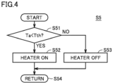
- Fig. 4 is a flowchart for illustrating energization control for the heater when the liquid discharge promotion control is started.
- controller 30 obtains an outside air temperature Ta from an outside air temperature sensor 8 and determines whether or not outside air temperature Ta is lower than a first threshold temperature Tth in step S51.
- controller 30 causes heater 40 to be energized to heat the liquid refrigerant in compressor 1 by heater 40 for a delay time of 30 minutes.
- controller 30 does not cause heater 40 to be energized, and waits until the liquid refrigerant in compressor 1 is warmed up by the outside air temperature while the heater is off in the delay time of 30 minutes.
- the refrigeration cycle apparatus sets the pause time period of compressor 1 for the fourth and subsequent start retries longer than the pause time period for the first start retry.
- the liquid refrigerant in compressor 1 can be heated by heater 40 or by the outside air temperature, and discharged sufficiently from compressor 1. In this way, the liquid amount in compressor 1 can be reduced to suppress unsuccessful start due to overcurrent abnormality at the time of the start retry.
- the present embodiment relates to cold source unit 100 connected to load apparatus 110 and serving as a component of refrigeration cycle apparatus 200.
- Cold source unit 100 includes compressor 1 and controller 30 to control compressor 1.
- controller 30 detects overload on compressor 1, controller 30 performs first start retry control of restarting compressor 1 after pausing compressor 1 for a first time period.
- controller 30 performs second start retry control of restarting compressor 1 after pausing compressor 1 for a second time period longer than the first time period.
- the second time period is a time period required for the amount of liquid in compressor 1 to be reduced enough to enable compressor 1 to be restarted.
- the amount of liquid refrigerant in compressor 1 is expected to be smaller than that when the first start retry control is performed, and therefore, overload on compressor 1 is removed to increase the possibility of success of restart of compressor 1.
- cold source unit 100 further includes heater 40 to heat liquid refrigerant in compressor 1.
- controller 30 performs the second start retry control
- controller 30 causes the liquid refrigerant to be heated by heater 40.
- the amount of liquid in compressor 1 is expected to be reduced by further promotion of evaporation of the liquid refrigerant in compressor 1 by heater 40, and therefore, the overload on compressor 1 when started is removed to further increase the possibility of success of restart of compressor 1.
- controller 30 when outside air temperature Ta is less than or equal to first threshold temperature Tth, controller 30 performs the second start retry control while causing the liquid refrigerant to be heated by heater 40. When outside air temperature Ta is more than first threshold temperature Tth, controller 30 performs the second start retry control while stopping heating of the liquid refrigerant by heater 40.
- controller 30 performs the first start retry control.
- controller 30 when liquid refrigerant is not sucked into compressor 1, controller 30 still performs the first start retry control regardless of that the number of times the first start retry control is performed exceeds the first criterion value (three, for example). Controller 30 determines whether or not the liquid refrigerant is sucked into compressor 1, based on at least one of superheat of refrigerant sucked into compressor 1, shell-bottom temperature of compressor 1, and superheat of refrigerant in compressor 1.
- controller 30 when controller 30 is unsuccessful in starting compressor 1 by the second start retry control, controller 30 repeats the second start retry control.
- controller 30 sets compressor 1 in a paused state.
- the first criterion value is 60% to a sum of the first criterion value and the second criterion value.
- the first retry control is performed three times, and then the retry control is performed twice.
- controller 30 sets compressor 1 in the paused state.
- the first criterion value is 3
- the second criterion value is 2
- the first criterion value is 60% to the sum of the first criterion value and the second criterion value.
- the maximum effect of liquid discharge is expected to be derived from a pause of 60 minutes (30 min ⁇ 2 times) in total, and therefore, liquid discharge is done when the start retry is done more than three times out of five times.
Description
- The present invention relates to a cold source unit.
- In a conventional refrigerator or the like, for example, a large amount of liquid refrigerant in the unit may return into the accumulator upon start of operation after defrosting. At this time, a large amount of liquid refrigerant flows in an oil return circuit located in a lower portion of the accumulator, and an excessive amount of this liquid refrigerant may flow from the oil return circuit into the compressor, i.e., a liquid return phenomenon (hereinafter "liquid back") may occur. The liquid back during operation causes a pressure surge in the compressor, resulting a problem that the operating current for the compressor becomes overcurrent.
-
Japanese Patent Laying-Open No. H06-034224 - Document
JP 5342528 B2 claim 1. -
- PTL 1:
JP H06 34224 A - PTL 2:
JP 5 342528 B2 - If the compressor is restarted with liquid refrigerant accumulated in the compressor due to the liquid back, increase of the load on a motor of the compressor for compressing the liquid may cause overcurrent to cause the compressor to be stopped temporarily. A technique disclosed in
Japanese Patent Laying-Open No. H06-034224 - The present invention is made to solve the problem as described above, and an object of the present invention is to provide a cold source unit and a refrigeration cycle apparatus that improve the probability of success of restart of the compressor when the compressor is stopped due to overcurrent.
- According to the present invention, a cold source unit as defined in the
independent claim 1 is provided. Further embodiments of the invention are defined in the dependent claims. The present invention relates to a cold source unit connected to a load apparatus and serving as a component of a refrigeration cycle apparatus. The cold source unit includes a compressor, and a controller to control the compressor. When the controller detects overload on the compressor, the controller performs first start retry control of restarting the compressor after pausing the compressor for a first time period. When the number of times of performing of the first start retry control exceeds a first criterion value, the controller performs second start retry control of restarting the compressor after pausing the compressor for a second time period longer than the first time period. - According to the present invention, when the compressor is not started successfully, the compressor is restarted after an increased waiting time, and therefore, liquid refrigerant in the compressor is discharged to improve the probability of success of the restart.
-
-
Fig. 1 shows a refrigerant circuit of arefrigeration cycle apparatus 200 according to an embodiment of the present invention. -
Fig. 2 shows a relation between the pause time period of a compressor and the rate of change of the liquid amount in the compressor. -
Fig. 3 is a flowchart for illustrating control for performing compressor start retry. -
Fig. 4 is a flowchart for illustrating energization control for a heater when liquid discharge promotion control is started. - Embodiments of the present invention are hereinafter described in detail with reference to the drawings. In the following, a plurality of embodiments are described, and it is originally intended that characteristics described in connection with the embodiments each are combined as appropriate. In the drawings, the same or corresponding parts are denoted by the same reference characters, and a description thereof is not herein repeated. In the following drawings, the relation between components in terms of the size may be different from the actual one.
-
Fig. 1 shows a refrigerant circuit of arefrigeration cycle apparatus 200 according to the present embodiment. As shown inFig. 1 ,refrigeration cycle apparatus 200 includes acold source unit 100 and aload apparatus 110. "Cold source unit" may also be called "heat source unit." -
Load apparatus 110 includes anexpansion valve 3 and a first heat exchanger (hereinafter referred to as evaporator 4).Cold source unit 100 is connected toload apparatus 110 and serves as a part ofrefrigeration cycle apparatus 200.Cold source unit 100 includes acompressor 1, a second heat exchanger (hereinafter referred to as condenser 2), aheater 40, and acontroller 30 tocontrol compressor 1 andheater 40. -
Controller 30 includes a CPU (Central Processing Unit) 31, a memory 32 (ROM (Read Only Memory) and RAM (Random Access Memory)), and an input/output device (not shown) for allowing various signals to be input, for example.CPU 31 deploys a program stored in the ROM on the RAM for example and executes the program. The program stored in the ROM is a program in which a process procedure forcontroller 30 is specified. In accordance with the program,controller 30 controls each component ofcold source unit 100. This control is not limited to processing by software, but may be processing by dedicated hardware (electronic circuit). -
Compressor 1 is equipped with athermistor 5 that detects the suction temperature, athermistor 6 that detects the temperature of a lower portion of a housing shell ofcompressor 1 or the temperature of refrigeration oil remaining in the housing of compressor 1 (hereinafter referred to as "shell-bottom temperature"), and acurrent sensor 7 that detects overcurrent. - In
refrigeration cycle apparatus 200,compressor 1 compresses refrigerant gas into high-pressure gas, and the high-pressure gas refrigerant flows intocondenser 2. Incondenser 2, heat is released from the refrigerant and the high-pressure gas refrigerant is condensed into high-pressure liquid refrigerant. The high-pressure liquid refrigerant flows intoexpansion valve 3. Inexpansion valve 3, the pressure of the high-pressure liquid refrigerant is reduced and the resultant low-pressure liquid refrigerant flows into evaporator 4. In evaporator 4, the liquid refrigerant is evaporated to absorb heat from the environment, i.e., cooling is done. The evaporated gas refrigerant returns intocompressor 1. Thus, a refrigerant circuit is completed. - According to the present embodiment,
compressor 1 is paused when overload is detected, and a sufficient pause time period is ensured to reduce the amount of liquid incompressor 1 and thereby suppress unsuccessful start when the start retry is made. For example, when overcurrent is detected bycurrent sensor 7,controller 30 detects that load oncompressor 1 is overload. - Specifically, when
controller 30 detects overload oncompressor 1,controller 30 performs first start retry control, i.e., restartscompressor 1 after pausingcompressor 1 for a first time period. When the number of times the first start retry control is performed exceeds a criterion value,controller 30 performs second start retry control, i.e., restartscompressor 1 after pausingcompressor 1 for a second time period longer than the first time period. The first time period can be 3 minutes and the second time period can be 30 minutes. The pause time period, however, is not limited to the above-specified ones. -
Fig. 2 shows a relation between the pause time period of the compressor and the rate of change of the liquid amount in the compressor. In consideration of the relation shown inFig. 2 and increase of the internal temperature of a refrigerator compartment resultant from pause of the compressor, the compressor pause time period per liquid discharge promotion control is determined. - If the compressor is paused with the inside of the refrigerator compartment cooled by normal operation, the time for which increase of the internal temperature of the refrigerator compartment is permissible is approximately 60 minutes. If, however, the liquid amount has been reduced enough, before 60 minutes elapse, to cause no overcurrent when
compressor 1 is started, the pause time period should be as short as possible. According to the present embodiment, therefore, the liquid discharge promotion control is performed up to twice, and the compressor pause time period per liquid discharge promotion control is set to 30 minutes. -
Fig. 3 is a flowchart for illustrating control for performing compressor start retry. Based on this flowchart, improvement to avoid unsuccessful start due to overcurrent abnormality is described. - In step S1, initially
controller 30 determines whether or not the start retry control in response to overcurrent has been performed five times. - When the start retry control has been performed five times in total (YES in S 1), controller proceeds to step S10 to give a notification of stoppage due to abnormality, so as not to perform the start retry control any more. For example, a light-emitting diode is lit to enable users to identify stoppage due to abnormality.
- When the start retry control has not been performed five times in total (NO in S1),
controller 30 proceeds to step S2 to determine whether or not the start retry control has been performed three times in total. - When the start retry control has not been performed three times in total (NO in S2),
controller 30 proceeds to step S11 to perform normal start retry control for the compressor. In this case, for example, compressor restart is attempted by energizingcompressor 1 after keeping the compressor paused for three minutes. The period of three minutes is a time period determined for preventing repeated start and pause ofcompressor 1 in which the amount of liquid refrigerant is small. - In contrast, when the start retry control has been performed three times in total (YES in S2),
controller 30 proceeds to step S3. - As a rule, when the answer is YES in step S2, control is performed from step S5 in which start of
compressor 1 is delayed more than before. It should be noted that, in order to prevent malfunction due to failure to cool resultant from long-time pause ofcompressor 1, or in order to perform another control of higher priority, start ofcompressor 1 may be repeated up to five times as before, without performing the process from step S5, in some cases. This situation may occur in the following cases, for example. - Priority has to be given to cooling, because the internal temperature of the refrigerator compartment is a certain threshold or more due to defrosting, or because the refrigeration capacity of the cold source unit is insufficient, for example.
- No liquid back occurs.
- Oil-return control is started due to shortage of refrigeration oil in
compressor 1. - The pressure at the discharge side and the pressure at the suction side of
compressor 1 may be reversed to each other. - Malfunction occurs due to open- or short-circuit detected by a low-pressure sensor.
- For each of all these cases, a determination may be made as to whether or not such a condition occurs. According to the present embodiment, however, the determination in each of steps S3 and S4 is made before proceeding to step S5.
- In step S3,
controller 30 determines whether or not any one of the superheat of the sucked refrigerant (suction SH), the shell-bottom temperature, and the superheat of refrigeration oil remaining in the shell of compressor 1 (hereinafter "shell-bottom SH"), measured bythermistor 5 andthermistor 6, is kept lower than a reference value associated to each for a certain period of time (three minutes, for example). In this way,controller 30 determines whether or not the liquid back occurs. - The superheat (SH) is a temperature difference between the actually measured refrigerant temperature and the saturated gas temperature at a measured pressure.
- When the suction SH is kept lower by 10 K than a target value for three minutes, for example,
controller 30 detects occurrence of the liquid back. - When all the suction SH, the shell-bottom temperature, and the shell-bottom SH are not kept lower than the reference value for a certain period of time (NO in S3),
controller 30 performs the normal start retry control for the compressor in step S12. In this case, for example, compressor restart is attempted by energizingcompressor 1 after keeping the compressor paused for three minutes. - In contrast, when any of the suction SH, the shell-bottom temperature, and the shell-bottom SH is kept lower than the reference value for a certain period of time (YES in S3),
controller 30 proceeds to step S4. - In step S4,
controller 30 determines whether or not an evaporation temperature ET is lower than a target evaporation temperature ETm+10K (kelvin). When the difference between evaporation temperature ET and target evaporation temperature ETm is less than or equal to 10K, it is determined that the inside of the refrigerator compartment can be kept cooled even when the compressor is paused for some time. While evaporation temperature ET may be measured with a temperature sensor provided for evaporator 4, the temperature detected bythermistor 5 which detects the suction temperature may be used instead. - When ET < ETm+10K is not satisfied (NO in S4),
controller 30 performs the normal start retry control for the compressor in step S13. In this case, for example, compressor restart is attempted by energizingcompressor 1 after keeping the compressor paused for three minutes. This is for the following reason. If the internal temperature of the refrigerator compartment after defrosting is high, or if the internal temperature of the refrigerator compartment is high due to insufficient refrigeration capacity of the cold source unit to which a plurality of load units are connected, the pause time period of 30 minutes is too long. - When ET < ETm+10K is satisfied (YES in S4),
controller 30 starts, in step S5, the liquid discharge promotion control for delaying start ofcompressor 1. Then, measurement of the time from stoppage ofcompressor 1 is started. Such a measured time from the stoppage ofcompressor 1 to restart thereof is herein referred to as "delay time." In order to sufficiently reduce liquid refrigerant incompressor 1,controller 30 keeps stoppingcompressor 1 until the delay time reaches a second time period (30 minutes, for example). The second time period is set longer than the first time period (3 minutes, for example) that is the pause time period in steps S11, S12, and S13. At this time, the situation in which the liquid discharge promotion control is performed is determined by a user, and therefore, it is preferable to show "Lout" or the like on a liquid crystal display of a control panel mounted on the refrigeration apparatus. - In step S6, initially it is determined whether or not the delay time has reached the set time (30 minutes, for example). When the delay time has reached the set time (YES in S6), start retry for
compressor 1 is performed in step S14. - In contrast, when the delay time has not reached the set time (NO in S6), the process proceeds to step S7. In step S7, it is determined whether or not a request to start oil return control is made. The oil return control is requested when shortage of the refrigeration oil in
compressor 1 occurs, in order to prevent burning ofcompressor 1. - When a request to start the oil return control is made (YES in S7), start retry for
compressor 1 is performed in step S15. - In contrast, when the request to start the oil return control is not made (NO in S7), the process proceeds to step S8. In step S8, it is determined whether or not a request to start high-low pressure reverse prevention control is made. The high-low pressure reverse prevention control is requested when it is detected that the pressure at the suction port side of
compressor 1 is higher than the pressure at the discharge port side. - When the request to start the high-low pressure reverse prevention control is made (YES in S8), start retry for
compressor 1 is performed in step S16. - In contrast, when the request to start the high-low pressure reverse prevention control is not made (NO in S8), the process proceeds to step S9. In step S9, it is determined whether or not evaporation temperature ET is kept higher than or equal to target evaporation temperature ETm+10K (kelvin) for three minutes.
- When the relation: Et ≥ ETm+10K is kept satisfied for three minutes (YES in S9), start retry for
compressor 1 is performed in step S17, since increase of the internal temperature of the refrigerator compartment is not permissible. Because evaporation temperature Et may momentarily exceed the threshold, the fact that the above relation is kept satisfied for three minutes is used as a condition for stopping delay of start. - When Et ≥ target evaporation temperature ETm+10K (kelvin) is kept satisfied for less than three minutes (NO in S9), the process returns to step S6 and measurement of the delay time to the start of the compressor start retry is continued.
- When the start retry for
compressor 1 is performed in any of steps S11 to S17,controller 30 determines in step S18 whether or not the start ofcompressor 1 has normally been completed. - For example, when overcurrent is detected again, it is determined that the start of
compressor 1 is not in success (NO in S18), energization of the motor ofcompressor 1 is stopped, andcompressor 1 is thus stopped. In this case, in step S19,controller 30 increments, by one, the number of times the start retry is performed, and performs the process again from step S1. - When the start retry fails to start the compressor after the liquid refrigerant discharge promotion control is performed twice, operation is stopped in step S10. At this time, it is determined that the cause of detection of overcurrent abnormality is not liquid back.
- When overcurrent is not detected, it is determined that
compressor 1 is started successfully (YES in S18), and the count of the start retry is initialized in step S20, and the process returns to the control routine for the normal operating state ofnormal compressor 1 in step S21. - When the liquid discharge promotion control is started in step S5,
heater 40 is additionally used for heating. When the outside air temperature is high, however,heater 40 may be stopped for saving energy. -
Fig. 4 is a flowchart for illustrating energization control for the heater when the liquid discharge promotion control is started. Referring toFig. 4 ,controller 30 obtains an outside air temperature Ta from an outsideair temperature sensor 8 and determines whether or not outside air temperature Ta is lower than a first threshold temperature Tth in step S51. - When Ta < Tth is satisfied (YES in S51),
controller 30 causesheater 40 to be energized to heat the liquid refrigerant incompressor 1 byheater 40 for a delay time of 30 minutes. In contrast, when Ta <Tth is not satisfied (NO in S51),controller 30 does not causeheater 40 to be energized, and waits until the liquid refrigerant incompressor 1 is warmed up by the outside air temperature while the heater is off in the delay time of 30 minutes. - In this way, whether to perform heating by the heater is determined depending on the outside air temperature so as not to heat the refrigerant more than necessary, and accordingly the power consumption can be reduced.
- As seen from the foregoing, the refrigeration cycle apparatus according to the present embodiment sets the pause time period of
compressor 1 for the fourth and subsequent start retries longer than the pause time period for the first start retry. Thus, even when the liquid amount incompressor 1 is increased due to the liquid back, the liquid refrigerant incompressor 1 can be heated byheater 40 or by the outside air temperature, and discharged sufficiently fromcompressor 1. In this way, the liquid amount incompressor 1 can be reduced to suppress unsuccessful start due to overcurrent abnormality at the time of the start retry. - Finally, the present embodiment is summarized with reference again to the drawings.
- Referring to
Fig. 1 , the present embodiment relates tocold source unit 100 connected to loadapparatus 110 and serving as a component ofrefrigeration cycle apparatus 200.Cold source unit 100 includescompressor 1 andcontroller 30 to controlcompressor 1. Whencontroller 30 detects overload oncompressor 1,controller 30 performs first start retry control of restartingcompressor 1 after pausingcompressor 1 for a first time period. When the number of times the first start retry control is performed exceeds a first criterion value,controller 30 performs second start retry control of restartingcompressor 1 after pausingcompressor 1 for a second time period longer than the first time period. - Preferably, the second time period is a time period required for the amount of liquid in
compressor 1 to be reduced enough to enablecompressor 1 to be restarted. - Accordingly, when the second start retry control is performed, the amount of liquid refrigerant in
compressor 1 is expected to be smaller than that when the first start retry control is performed, and therefore, overload oncompressor 1 is removed to increase the possibility of success of restart ofcompressor 1. - Preferably,
cold source unit 100 further includesheater 40 to heat liquid refrigerant incompressor 1. Whencontroller 30 performs the second start retry control,controller 30 causes the liquid refrigerant to be heated byheater 40. - Thus, when the second retry control is performed, the amount of liquid in
compressor 1 is expected to be reduced by further promotion of evaporation of the liquid refrigerant incompressor 1 byheater 40, and therefore, the overload oncompressor 1 when started is removed to further increase the possibility of success of restart ofcompressor 1. - More preferably, as shown in
Fig. 4 , when outside air temperature Ta is less than or equal to first threshold temperature Tth,controller 30 performs the second start retry control while causing the liquid refrigerant to be heated byheater 40. When outside air temperature Ta is more than first threshold temperature Tth,controller 30 performs the second start retry control while stopping heating of the liquid refrigerant byheater 40. - Thus, when outside air temperature Ta is high and accordingly the amount of liquid refrigerant in
compressor 1 is reduced within the waiting time corresponding to the second time period, without requiring heating byheater 40,heater 40 is not energized and the power consumption can therefore be reduced. - Preferably, as shown in step S4 in
Fig. 3 , when a difference between refrigerant evaporation temperature ET and target refrigerant evaporation temperature ETm is less than a second threshold temperature (10 K for example),controller 30 performs the first start retry control. - Thus, when the internal temperature of the refrigerator compartment is high after defrosting or the refrigeration capacity of the cold source unit is insufficient to cause evaporation temperature ET to be higher than target evaporation temperature ETm to some extent, further increase of the internal temperature of the refrigerator compartment resultant from the start time delay can be avoided.
- Preferably, as shown in step S3 in
Fig. 3 , when liquid refrigerant is not sucked intocompressor 1,controller 30 still performs the first start retry control regardless of that the number of times the first start retry control is performed exceeds the first criterion value (three, for example).Controller 30 determines whether or not the liquid refrigerant is sucked intocompressor 1, based on at least one of superheat of refrigerant sucked intocompressor 1, shell-bottom temperature ofcompressor 1, and superheat of refrigerant incompressor 1. - When no liquid back occurs, overload is not removed even when start of
compressor 1 is delayed, and therefore, increase of the internal temperature of the refrigerator compartment due to delay of start ofcompressor 1 can thus be avoided. - Preferably, when
controller 30 is unsuccessful in startingcompressor 1 by the second start retry control,controller 30 repeats the second start retry control. When the number of times the second start retry control is performed exceeds a second criterion value,controller 30sets compressor 1 in a paused state. The first criterion value is 60% to a sum of the first criterion value and the second criterion value. - Specifically, according to the flowchart in
Fig. 3 , the first retry control is performed three times, and then the retry control is performed twice. When start ofcompressor 1 is still unsuccessful regardless of this,controller 30sets compressor 1 in the paused state. As seen from this, the first criterion value is 3, the second criterion value is 2, and the first criterion value is 60% to the sum of the first criterion value and the second criterion value. The maximum effect of liquid discharge is expected to be derived from a pause of 60 minutes (30 min × 2 times) in total, and therefore, liquid discharge is done when the start retry is done more than three times out of five times. - It should be construed that the embodiments disclosed herein are given by way of illustration in all respects, not by way of limitation. It is intended that the scope of the present invention is defined by claims, not by the above description of the embodiments.
- 1 compressor; 2 condenser; 3 expansion valve; 4 evaporator; 5, 6 thermistor; 7 current sensor; 8 outside air temperature sensor; 30 controller; 31 CPU; 32 memory; 40 heater; 100 cold source unit; 110 load apparatus; 200 refrigeration cycle apparatus
Claims (6)
- A cold source unit (100) connected to a load apparatus (110) and serving as a component of a refrigeration cycle apparatus (200), the cold source unit (100) comprising:a compressor (1); anda controller (30) to control the compressor (1), whereinwhen the controller (30) detects overload on the compressor (1), the controller (30) performs first start retry control of restarting the compressor (1) after pausing the compressor (1) for a first time period, whereinwhen the number of times of performing of the first start retry control exceeds a first criterion value, the controller (30) performs second start retry control of restarting the compressor (1) after pausing the compressor (1) for a second time period longer than the first time period,characterized in that the cold source unit (100) further comprises a heating apparatus (40) to heat liquid refrigerant in the compressor (1), whereinwhen the controller (30) performs the second start retry control, the controller (30) causes the liquid refrigerant to be heated by the heating apparatus (40).
- The cold source unit (100) according to claim 1, whereinwhen an outside air temperature is less than or equal to a first threshold temperature, the controller (30) performs the second start retry control while causing the liquid refrigerant to be heated by the heating apparatus (40), andwhen the outside air temperature is more than the first threshold temperature, the controller (30) performs the second start retry control while stopping heating of the liquid refrigerant by the heating apparatus (40).
- The cold source unit (100) according to any one of claims 1 to 2, wherein when a difference between a refrigerant evaporation temperature and a target refrigerant evaporation temperature is less than a second threshold temperature, the controller (30) performs the first start retry control.
- The cold source unit (100) according to any one of claims 1 to 3, wherein the second time period is a time period required for a liquid amount in the compressor (1) to be reduced enough to enable the compressor (1) to be restarted.
- The cold source unit (100) according to any one of claims 1 to 4, whereinwhen the controller (30) is unsuccessful in starting the compressor (1) by the second start retry control, the controller (30) repeats the second start retry control,when the number of times of performing of the second start retry control exceeds a second criterion value, the controller (30) sets the compressor (1) in a paused state, andthe first criterion value is 60% to a sum of the first criterion value and the second criterion value.
- A refrigeration cycle apparatus (200) comprising the cold source unit (100) according to any one of claims 1 to 5, and the load apparatus (110).
Applications Claiming Priority (1)
| Application Number | Priority Date | Filing Date | Title |
|---|---|---|---|
| PCT/JP2019/044891 WO2021095237A1 (en) | 2019-11-15 | 2019-11-15 | Cold heat source unit and refrigeration circuit device |
Publications (3)
| Publication Number | Publication Date |
|---|---|
| EP4060250A1 EP4060250A1 (en) | 2022-09-21 |
| EP4060250A4 EP4060250A4 (en) | 2022-10-26 |
| EP4060250B1 true EP4060250B1 (en) | 2024-02-28 |
Family
ID=75911485
Family Applications (1)
| Application Number | Title | Priority Date | Filing Date |
|---|---|---|---|
| EP19952629.4A Active EP4060250B1 (en) | 2019-11-15 | 2019-11-15 | Cold heat source unit and refrigeration circuit device |
Country Status (4)
| Country | Link |
|---|---|
| EP (1) | EP4060250B1 (en) |
| JP (1) | JP7399182B2 (en) |
| CN (1) | CN114729765A (en) |
| WO (1) | WO2021095237A1 (en) |
Families Citing this family (2)
| Publication number | Priority date | Publication date | Assignee | Title |
|---|---|---|---|---|
| CN113432343B (en) * | 2021-05-28 | 2023-02-03 | 青岛海尔空调电子有限公司 | Oil return control method of refrigeration and freezing unit and refrigeration and freezing unit |
| CN113418327B (en) * | 2021-05-28 | 2023-02-28 | 青岛海尔空调电子有限公司 | Oil return control method of refrigeration and freezing unit and refrigeration and freezing unit |
Family Cites Families (19)
| Publication number | Priority date | Publication date | Assignee | Title |
|---|---|---|---|---|
| JPH0833246B2 (en) * | 1990-08-06 | 1996-03-29 | ダイキン工業株式会社 | Refrigeration system operation controller |
| JP2914020B2 (en) | 1992-07-17 | 1999-06-28 | 松下電器産業株式会社 | Heating and cooling machine |
| JPH06123514A (en) * | 1992-10-12 | 1994-05-06 | Matsushita Electric Ind Co Ltd | Heating and cooling device |
| JPH08261571A (en) * | 1995-03-20 | 1996-10-11 | Matsushita Electric Ind Co Ltd | Method for actuating compression type freezer |
| JPH09149547A (en) * | 1995-11-24 | 1997-06-06 | Matsushita Electric Ind Co Ltd | Apparatus and method for controlling air conditioner operation |
| JPH10205895A (en) * | 1997-01-28 | 1998-08-04 | Matsushita Refrig Co Ltd | Refrigeration cycle controller |
| JP3175706B2 (en) * | 1998-09-30 | 2001-06-11 | ダイキン工業株式会社 | Binary refrigeration equipment |
| JP4327936B2 (en) | 1999-04-08 | 2009-09-09 | 三菱電機株式会社 | Heat pump refrigeration system |
| US6119469A (en) * | 1999-06-14 | 2000-09-19 | Spx Corporation | Programmable electronic start-up delay for refrigeration units |
| US6578373B1 (en) * | 2000-09-21 | 2003-06-17 | William J. Barbier | Rate of change detector for refrigerant floodback |
| KR100484800B1 (en) * | 2002-06-19 | 2005-04-22 | 엘지전자 주식회사 | Compressor's Operating Method in Air Conditioner |
| JP4273492B2 (en) | 2003-12-18 | 2009-06-03 | 三菱電機株式会社 | Air conditioning apparatus and refrigeration apparatus |
| JP5203754B2 (en) * | 2008-03-11 | 2013-06-05 | 株式会社日立産機システム | Inverter compressor control method and inverter compressor |
| JP5558132B2 (en) * | 2010-02-16 | 2014-07-23 | 三菱電機株式会社 | Refrigerator and refrigeration apparatus to which the refrigerator is connected |
| JP5342528B2 (en) * | 2010-09-25 | 2013-11-13 | 日立アプライアンス株式会社 | Air conditioner with active filter |
| JP6440930B2 (en) | 2013-06-20 | 2018-12-19 | 三菱重工サーマルシステムズ株式会社 | Air conditioner and control method of air conditioner |
| CN108369046B (en) * | 2015-12-11 | 2020-07-28 | 三菱电机株式会社 | Refrigeration cycle device |
| WO2018073855A1 (en) * | 2016-10-17 | 2018-04-26 | 三菱電機株式会社 | Air conditioner |
| CN110192070A (en) * | 2017-01-25 | 2019-08-30 | 三菱电机株式会社 | Refrigerating circulatory device |
-
2019
- 2019-11-15 EP EP19952629.4A patent/EP4060250B1/en active Active
- 2019-11-15 WO PCT/JP2019/044891 patent/WO2021095237A1/en unknown
- 2019-11-15 JP JP2021555751A patent/JP7399182B2/en active Active
- 2019-11-15 CN CN201980102102.5A patent/CN114729765A/en active Pending
Also Published As
| Publication number | Publication date |
|---|---|
| JPWO2021095237A1 (en) | 2021-05-20 |
| EP4060250A4 (en) | 2022-10-26 |
| WO2021095237A1 (en) | 2021-05-20 |
| JP7399182B2 (en) | 2023-12-15 |
| CN114729765A (en) | 2022-07-08 |
| EP4060250A1 (en) | 2022-09-21 |
Similar Documents
| Publication | Publication Date | Title |
|---|---|---|
| EP4060250B1 (en) | Cold heat source unit and refrigeration circuit device | |
| EP1953477A1 (en) | Refrigerator compressor operating method and refrigerator | |
| KR100505231B1 (en) | A compressor driving method of air-conditioner having multi-compressor | |
| JP2002107014A (en) | Air conditioner | |
| US8418498B2 (en) | Refrigeration device and method for controlling a refrigeration device | |
| CN111322822B (en) | Control method of cascade ultralow temperature refrigerator | |
| JP2500522B2 (en) | Refrigeration system operation controller | |
| CN113418329A (en) | Control method of refrigeration and freezing unit and refrigeration and freezing unit | |
| JPH1030835A (en) | Controller for air conditioner | |
| WO2023221664A1 (en) | Control method and control apparatus for multi-split air conditioning system, and multi-split air conditioning system | |
| JPH09236336A (en) | Operation controller for air conditioner | |
| KR101097976B1 (en) | A method for controlling an operation of refrigerators | |
| AU2020468256A1 (en) | Refrigeration-cycle device, air conditioner comprising same, and method for controlling refrigeration-cycle device | |
| JP3260681B2 (en) | Air conditioner using non-azeotropic mixed refrigerant and operation control method of the air conditioner | |
| JPH10185334A (en) | Refrigerating equipment | |
| JP4318369B2 (en) | Screw type refrigerator | |
| EP4092355A1 (en) | Heat pump type heat source apparatus | |
| JP3219040B2 (en) | Refrigeration equipment | |
| JPH05288386A (en) | Operation controller for outdoor fan in air conditioner | |
| JP2927230B2 (en) | Binary refrigeration equipment | |
| CN116536900A (en) | Control method for refrigerating fan of heat pump clothes dryer, computer equipment and heat pump clothes dryer | |
| JP3147839B2 (en) | Refrigeration equipment | |
| JPH10253182A (en) | Binary refrigerating device | |
| JP6386778B2 (en) | Refrigeration equipment | |
| CN117346357A (en) | Defrosting control method of heat pump unit and related equipment |
Legal Events
| Date | Code | Title | Description |
|---|---|---|---|
| STAA | Information on the status of an ep patent application or granted ep patent |
Free format text: STATUS: THE INTERNATIONAL PUBLICATION HAS BEEN MADE |
|
| PUAI | Public reference made under article 153(3) epc to a published international application that has entered the european phase |
Free format text: ORIGINAL CODE: 0009012 |
|
| STAA | Information on the status of an ep patent application or granted ep patent |
Free format text: STATUS: REQUEST FOR EXAMINATION WAS MADE |
|
| 17P | Request for examination filed |
Effective date: 20220329 |
|
| AK | Designated contracting states |
Kind code of ref document: A1 Designated state(s): AL AT BE BG CH CY CZ DE DK EE ES FI FR GB GR HR HU IE IS IT LI LT LU LV MC MK MT NL NO PL PT RO RS SE SI SK SM TR |
|
| A4 | Supplementary search report drawn up and despatched |
Effective date: 20220928 |
|
| RIC1 | Information provided on ipc code assigned before grant |
Ipc: F24F 11/37 20180101ALI20220922BHEP Ipc: F04C 28/28 20060101ALI20220922BHEP Ipc: F04C 28/06 20060101ALI20220922BHEP Ipc: F25B 49/02 20060101ALI20220922BHEP Ipc: F25B 49/00 20060101ALI20220922BHEP Ipc: F25B 1/00 20060101AFI20220922BHEP |
|
| DAV | Request for validation of the european patent (deleted) | ||
| DAX | Request for extension of the european patent (deleted) | ||
| REG | Reference to a national code |
Ref country code: DE Ref legal event code: R079 Ref document number: 602019047594 Country of ref document: DE Free format text: PREVIOUS MAIN CLASS: F25B0001000000 Ipc: F04B0049020000 Ref legal event code: R079 Ipc: F04B0049020000 |
|
| GRAP | Despatch of communication of intention to grant a patent |
Free format text: ORIGINAL CODE: EPIDOSNIGR1 |
|
| STAA | Information on the status of an ep patent application or granted ep patent |
Free format text: STATUS: GRANT OF PATENT IS INTENDED |
|
| RIC1 | Information provided on ipc code assigned before grant |
Ipc: F04C 28/28 20060101ALI20230814BHEP Ipc: F04C 28/06 20060101ALI20230814BHEP Ipc: F24F 11/37 20180101ALI20230814BHEP Ipc: F25B 49/02 20060101ALI20230814BHEP Ipc: F25B 49/00 20060101ALI20230814BHEP Ipc: F24F 140/50 20180101ALI20230814BHEP Ipc: F04B 49/06 20060101ALI20230814BHEP Ipc: F04B 49/02 20060101AFI20230814BHEP |
|
| INTG | Intention to grant announced |
Effective date: 20230920 |
|
| P01 | Opt-out of the competence of the unified patent court (upc) registered |
Effective date: 20231103 |
|
| GRAS | Grant fee paid |
Free format text: ORIGINAL CODE: EPIDOSNIGR3 |
|
| GRAA | (expected) grant |
Free format text: ORIGINAL CODE: 0009210 |
|
| STAA | Information on the status of an ep patent application or granted ep patent |
Free format text: STATUS: THE PATENT HAS BEEN GRANTED |
|
| AK | Designated contracting states |
Kind code of ref document: B1 Designated state(s): AL AT BE BG CH CY CZ DE DK EE ES FI FR GB GR HR HU IE IS IT LI LT LU LV MC MK MT NL NO PL PT RO RS SE SI SK SM TR |
|
| REG | Reference to a national code |
Ref country code: GB Ref legal event code: FG4D |
|
| REG | Reference to a national code |
Ref country code: CH Ref legal event code: EP |
|
| REG | Reference to a national code |
Ref country code: DE Ref legal event code: R096 Ref document number: 602019047594 Country of ref document: DE |
|
| REG | Reference to a national code |
Ref country code: IE Ref legal event code: FG4D |