WO2021084637A1 - ソレノイド装置、およびスタータ - Google Patents
ソレノイド装置、およびスタータ Download PDFInfo
- Publication number
- WO2021084637A1 WO2021084637A1 PCT/JP2019/042507 JP2019042507W WO2021084637A1 WO 2021084637 A1 WO2021084637 A1 WO 2021084637A1 JP 2019042507 W JP2019042507 W JP 2019042507W WO 2021084637 A1 WO2021084637 A1 WO 2021084637A1
- Authority
- WO
- WIPO (PCT)
- Prior art keywords
- terminal
- connection terminal
- electrically connected
- coil
- absorbing element
- Prior art date
Links
Images


Classifications
-
- H—ELECTRICITY
- H01—ELECTRIC ELEMENTS
- H01F—MAGNETS; INDUCTANCES; TRANSFORMERS; SELECTION OF MATERIALS FOR THEIR MAGNETIC PROPERTIES
- H01F7/00—Magnets
- H01F7/06—Electromagnets; Actuators including electromagnets
- H01F7/08—Electromagnets; Actuators including electromagnets with armatures
- H01F7/081—Magnetic constructions
-
- H—ELECTRICITY
- H01—ELECTRIC ELEMENTS
- H01F—MAGNETS; INDUCTANCES; TRANSFORMERS; SELECTION OF MATERIALS FOR THEIR MAGNETIC PROPERTIES
- H01F27/00—Details of transformers or inductances, in general
- H01F27/28—Coils; Windings; Conductive connections
- H01F27/29—Terminals; Tapping arrangements for signal inductances
-
- F—MECHANICAL ENGINEERING; LIGHTING; HEATING; WEAPONS; BLASTING
- F02—COMBUSTION ENGINES; HOT-GAS OR COMBUSTION-PRODUCT ENGINE PLANTS
- F02N—STARTING OF COMBUSTION ENGINES; STARTING AIDS FOR SUCH ENGINES, NOT OTHERWISE PROVIDED FOR
- F02N11/00—Starting of engines by means of electric motors
- F02N11/08—Circuits or control means specially adapted for starting of engines
- F02N11/087—Details of the switching means in starting circuits, e.g. relays or electronic switches
-
- H—ELECTRICITY
- H01—ELECTRIC ELEMENTS
- H01F—MAGNETS; INDUCTANCES; TRANSFORMERS; SELECTION OF MATERIALS FOR THEIR MAGNETIC PROPERTIES
- H01F27/00—Details of transformers or inductances, in general
- H01F27/28—Coils; Windings; Conductive connections
- H01F27/32—Insulating of coils, windings, or parts thereof
- H01F27/324—Insulation between coil and core, between different winding sections, around the coil; Other insulation structures
- H01F27/325—Coil bobbins
-
- H—ELECTRICITY
- H01—ELECTRIC ELEMENTS
- H01F—MAGNETS; INDUCTANCES; TRANSFORMERS; SELECTION OF MATERIALS FOR THEIR MAGNETIC PROPERTIES
- H01F5/00—Coils
- H01F5/02—Coils wound on non-magnetic supports, e.g. formers
-
- H—ELECTRICITY
- H01—ELECTRIC ELEMENTS
- H01F—MAGNETS; INDUCTANCES; TRANSFORMERS; SELECTION OF MATERIALS FOR THEIR MAGNETIC PROPERTIES
- H01F5/00—Coils
- H01F5/04—Arrangements of electric connections to coils, e.g. leads
-
- H—ELECTRICITY
- H01—ELECTRIC ELEMENTS
- H01F—MAGNETS; INDUCTANCES; TRANSFORMERS; SELECTION OF MATERIALS FOR THEIR MAGNETIC PROPERTIES
- H01F7/00—Magnets
- H01F7/06—Electromagnets; Actuators including electromagnets
- H01F2007/062—Details of terminals or connectors for electromagnets
-
- H—ELECTRICITY
- H01—ELECTRIC ELEMENTS
- H01H—ELECTRIC SWITCHES; RELAYS; SELECTORS; EMERGENCY PROTECTIVE DEVICES
- H01H50/00—Details of electromagnetic relays
- H01H50/44—Magnetic coils or windings
- H01H2050/446—Details of the insulating support of the coil, e.g. spool, bobbin, former
Definitions
- This application relates to a solenoid device and a starter.
- Patent Document 1 discloses an electromagnetic relay including a solenoid device.
- a mounting wall of a terminal mounting portion is provided upright on a flange portion of a resin bobbin around which a coil is wound, and a pair of mounting walls are provided on both left and right sides of the mounting wall.
- a terminal holding portion for holding the coil terminal is provided, an intermediate terminal holding portion for holding the intermediate terminal is provided in the center of the mounting wall, and a pair of coil terminals are held in the terminal holding portions on both the left and right sides, respectively.
- An intermediate terminal is held in the terminal holding portion, and a pair of surge absorbing elements are arranged between the pair of coil terminals and the intermediate terminal.
- the conventional solenoid device in the electromagnetic relay disclosed in Patent Document 1 uses a package of an axial type surge absorbing element to which a lead wire is connected as a surge absorbing element, and the package of the surge absorbing element is welded by means such as welding. It is configured to be electrically connected to the coil terminal.
- an axial type surge absorbing element is relatively large, and in order to connect this surge absorbing element to a pair of coil terminals by welding on a bobbin around which a coil is wound, a relatively large welding space is required. It is necessary to secure a large amount. Therefore, the conventional solenoid device disclosed in Patent Document 1 needs to secure a relatively large welding space for connecting the surge absorbing element to the coil terminal by welding as described above, resulting in an increase in size. There was a problem.
- the starter for starting an engine equipped with a conventional solenoid device uses a solenoid device that needs to secure a relatively large welding space for connecting the surge absorbing element to the coil terminal by welding as described above. Therefore, there was a problem that the size was increased.
- the present application discloses a technique for solving the above-mentioned problems, and an object of the present application is to provide a solenoid device that realizes miniaturization.
- the present application aims to provide a starter that realizes miniaturization.
- the solenoid device disclosed in the present application is A bobbin having a flange at at least one end of the coil winding portion in the axial direction, A coil having a first coil terminal and a second coil terminal wound around the coil winding portion and led out from the flange portion to the outside of the bobbin.
- a solenoid device configured so that the first terminal of a surge absorbing element can be electrically connected to the positive electrode terminal and the second terminal of the surge absorbing element can be electrically connected to the negative electrode terminal.
- the fixed wall and the support wall are configured to be capable of holding the surge absorbing element, which is at least partially arranged in the space.
- the convex portion is configured to be able to press the held surge absorbing element toward the end face side of the flange portion based on the elastic force of the support wall. It is characterized by that.
- the starter disclosed in the present application is A relay device that is driven by the engine start signal to close the relay contacts, A solenoid device having a coil that is urged via the relay contact when the relay device is driven, and a solenoid switch that closes when the coil is urged.
- a surge absorbing element that absorbs the surge voltage generated in the coil
- a motor that is driven to start the engine when the solenoid switch is closed, It is a starter equipped with The solenoid device is composed of the above solenoid device. Characterized by
- FIG. 5 is a circuit diagram of a starter for starting an engine including a solenoid device according to the first embodiment. It is a perspective view which shows a part of the solenoid device by Embodiment 1. FIG. It is explanatory drawing which shows the procedure of attaching a surge absorption element to the bobbin in the solenoid device by Embodiment 1. FIG. It is explanatory drawing which shows the procedure of attaching a surge absorption element to the bobbin in the solenoid device by Embodiment 1. FIG. It is a side view which shows the state which the surge absorbing element is attached to the bobbin in the solenoid device by Embodiment 1. FIG.
- FIG. 5 is a perspective view showing another example of electrical connection between a surge absorbing element and a connection terminal portion in the solenoid device according to the first embodiment. It is a top view which shows the electrical connection between a surge absorption element and a connection terminal part in the solenoid device by Embodiment 2.
- FIG. It is a perspective view which shows the connection terminal part in the solenoid device by Embodiment 2.
- FIG. It is a perspective view which shows the connection terminal part in the solenoid device by Embodiment 3.
- FIG. 5 is a perspective view showing another example of electrical connection between a surge absorbing element and a connection terminal portion in the solenoid device according to the first embodiment. It is a top view which shows the electrical connection between a surge absorption element and a connection terminal part in the solenoid device by Embodiment 2.
- FIG. It is
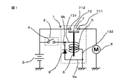
- FIG. 1 is a circuit diagram of a starter for starting an engine including a solenoid device according to the first embodiment.
- the solenoid device 1 is electrically connected to the battery 3 via the relay device 2.
- the solenoid device 1 includes a coil 5, a plunger 6 driven by the coil 5, a solenoid switch 7, a diode 9 as a surge absorbing element, and a bobbin 10 such as a synthetic resin in which the coil 5 is wound, which will be described later. ing.
- the solenoid switch 7 is fixed to the first fixed contact 711 connected to the motor 8, the second fixed contact 712 connected to the positive electrode of the battery 3, and the plunger 6, and the first fixed contact 711 and the second. It is provided with a movable contact 72 that contacts or separates from the fixed contact 712 of the above.
- the first coil terminal 131 is connected to the positive electrode of the battery 3 via the relay device 2, and the second coil terminal 132 is connected to the ground potential portion.
- the diode 9 as a surge absorbing element the anode terminal 9a is connected to the second coil terminal 132, and the cathode terminal 9b is connected to the first coil terminal 131.
- the relay contact 4 is closed, a current is supplied from the battery 3 to the coil 5 of the solenoid device 1, and a magnetic field is supplied to the coil 5. Occurs.
- the plunger 6 is driven by the magnetic field generated in the coil 5, and the movable contact 72 of the solenoid switch 7 that moves in conjunction with the operation of the plunger 6 comes into contact with the first fixed contact 711 and the second fixed contact 712, and the solenoid.
- the switch 7 closes.
- FIG. 2 is a perspective view showing a part of the solenoid device according to the first embodiment
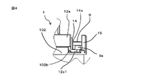
- FIG. 4 is a side view showing a state in which a surge absorbing element is attached to a bobbin in the solenoid device according to the first embodiment
- FIG. It is a top view which shows the state which the surge absorbing element is attached to the bobbin in the solenoid device by Embodiment 1.
- FIG. 1 is a perspective view showing a part of the solenoid device according to the first embodiment
- FIG. 4 is a side view showing a state in which a surge absorbing
- the synthetic resin bobbin 10 has a coil winding portion 101 formed in a cylindrical shape having a through hole in the center portion and one of the coil winding portions 101 in the axial direction. It includes a first flange portion 102 provided at an end portion and a second flange portion 103 provided at the other end portion in the axial direction of the coil winding portion 101.
- the first flange portion 102 has two notches 104 for leading the first coil terminal 131 and the second coil terminal 132 to the outside of the bobbin 10 (one notch portion in FIG. 2). Only 104 is shown).
- the coil 5 is introduced from one notch 104 of the first flange 102 to the outer peripheral surface of the coil winding 101 of the bobbin 10 and wound around the outer peripheral surface of the coil winding 101, and the other notch. It is derived from the unit 104 to the outside of the bobbin 10.
- the conductors of the coil 5 led out from the two notch portions 104 to the outside of the bobbin 10 form the first coil terminal 131 and the second coil terminal 132 described above, respectively.
- the axial end of the first flange portion 102 is an annular flat surface portion 102a orthogonal to the axial direction of the bobbin 10 and a cut-down surface portion cut down from the flat surface portion 102a toward the coil 5 in the axial direction of the bobbin 10. It has 102b.
- the cut-down surface portion 102b is formed by cutting down a part of the annular flat surface portion 102a in the vicinity of the outer peripheral edge portion.
- the support wall 14 is fixed to the cut-down surface portion 102b of the first flange portion 102, and the support wall 14 stands up from the cut-down surface portion 102b in the axial direction of the bobbin 10 and near the free end thereof in the radial direction of the first flange portion 102. It is provided with a convex portion 14a projecting to the outside of the.
- the convex portion 14a is provided on the wall surface of the support wall 14 facing the fixed wall 15 so as to extend parallel to the surface of the cut-down surface portion 102b.
- the support wall 14 is made of an elastic material, for example, an elastic synthetic resin.
- the fixed wall 15 is fixed to the outer peripheral edge of the cut-down surface portion 102b of the first flange portion 102, and the fixed wall 15 is provided so as to stand upright in the axial direction of the bobbin 10.
- the fixed wall 15 faces the support wall 14 and its convex portion 14a via a space.
- the convex portion 14a is provided so as to project into the space formed by the support wall 14 and the fixed wall 15.
- the support wall 14 and the fixed wall 15 may be integrally formed of the same material as the first flange portion 102, or the support wall 14 is formed separately from the first flange portion 102. And the fixing wall 15 may be provided on the first flange portion 102 as described above.
- the flat surface portion 102a of the first flange portion 102 is provided with a first protrusion 105 for holding the positive electrode terminal 11 and a second protrusion 106 for holding the negative electrode terminal 12.
- the first protrusion 105 and the second protrusion 106 are provided so as to project from the flat surface portion 102a of the first flange portion 102 in the axial direction of the bobbin 10, and face each other through the through hole of the bobbin 10. It is arranged like this.
- the first protrusion 105 and the second protrusion 106 are each formed integrally with the first flange 102.
- the first protrusion 105 and the second protrusion 106 which are formed separately from the first flange 102, are provided on the flat surface 102a of the first flange 102 as described above. You may.
- the positive electrode terminal 11 is inserted into the first protrusion 105 in the axial direction of the bobbin 10 and is fixed to the flat surface portion 102a of the first flange portion 102 via the first protrusion 105.
- the negative electrode terminal 12 is inserted into the second protrusion 106 in the axial direction of the bobbin 10 and is fixed to the flat surface portion 102a of the first flange portion 102 via the second protrusion 106.
- the positive electrode terminal 11 includes a first extending portion 11a and a second extending portion 11b extending along a flat surface portion 102a of the first flange portion 102 from a base portion inserted into the first protruding portion 105. ing.
- the first extending portion 11a and the second extending portion 11b are extended so as to extend in opposite directions from the first protruding portion 105, respectively.
- the first extension portion 11a and the second extension portion 11b of the positive electrode terminal 11 are led out to the outside of the first protrusion 105 from the notches provided in the first protrusion 105, respectively. ..
- the first extending portion 11a of the positive electrode terminal 11 is electrically joined to the first coil terminal 131 by welding, brazing, or the like.
- the second extending portion 11b of the positive electrode terminal 11 is bent outward from the second extending portion 11b in the radial direction of the first flange portion 102, and the back surface thereof is a cut-down surface portion. It includes a first connection terminal portion 11b1 arranged so as to face the 102b. The back surface of the first connection terminal portion 11b1 is in contact with the surface of the cut-down surface portion 102b of the first flange portion 102.
- the negative electrode terminal 12 includes an extending portion 12a extending from a base portion inserted into the second protruding portion 106 along a flat surface portion 102a of the first flange portion 102.
- the extending portion 12a of the negative electrode terminal 12 is led out from the notch portion provided in the second protruding portion 106 to the outside of the second protruding portion 106.
- the extending portion 12a of the negative electrode terminal 12 is electrically connected to the second coil terminal 132 by welding, brazing, or the like. Further, as is well shown in FIGS. 4 and 5, the extension portion 12a of the negative electrode terminal 12 is bent outward from the extension portion 12a of the negative electrode terminal 12 in the radial direction of the first flange portion 102.
- It includes a second connection terminal portion 12a1 whose back surface is arranged so as to face the cut-down surface portion 102b.
- the back surface of the second connection terminal portion 12a1 is in contact with the surface of the cut-down surface portion 102b of the first flange portion 102.
- the surface of the first connection terminal portion 11b1 in the second extension portion 11b of the positive electrode terminal 11 and the surface of the second connection terminal portion 12a1 in the extension portion 12a of the negative electrode terminal 12 are the support wall 14 and the fixed wall 15. They are arranged so as to face each other through the space formed between them.
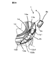
- FIG. 3A is an explanatory diagram showing a procedure for attaching a surge absorbing element to the bobbin in the solenoid device according to the first embodiment, and shows a state before attaching the diode 9 as the surge absorbing element to the bobbin 10.
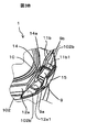
- FIG. 3B is an explanatory diagram showing a procedure for attaching a surge absorbing element to the bobbin in the solenoid device according to the first embodiment, and shows a state after the diode 9 as the surge absorbing element is attached to the bobbin 10.
- a surface-mounted diode used for substrate mounting or the like is used as the diode 9 as a surge absorbing element.
- the diode 9 is configured as, for example, a relatively thin package in which the shapes of the front surface and the back surface are formed in a rectangular shape, and the second terminals of the diode 9 are formed on the side surface portions on the short side facing each other.
- the anode terminal 9a as the first terminal of the diode 9 and the cathode terminal 9b as the first terminal of the diode 9 are exposed and provided.
- the first connection terminal portion 11b1 of the positive electrode terminal 11 and the first connection terminal portion 11b1 of the positive electrode terminal 11 are formed in the space between the fixed wall 15 and the support wall 14 provided on the bobbin 10.
- the second connection terminal portion 12a1 of the negative electrode terminal 12 is exposed.
- the pair of long side portions of the diode 9 facing each other are made to correspond to each other so as to be parallel to the wall surfaces of the fixed wall 15 and the supporting wall 14 facing each other.
- the diode 9 is pushed in the direction of the first flange portion 102 in the axial direction of the bobbin 10 from the upper end side of the fixed wall 15 and the support wall 14.
- the convex portion 14a When the diode 9 passes through the convex portion 14a provided on the support wall 14, the convex portion 14a is pressed against the side surface of the diode 9 inward in the radial direction of the first flange portion 102, so that the support wall has elasticity. 14 bends inward in the radial direction of the first flange portion 102, but when the diode 9 passes through the convex portion 14a, the elastic support wall 14 returns to its original position. After passing through the convex portion 14a, the diode 9 is placed on the surface of the first connection terminal portion 11b1 of the positive electrode terminal 11 and the surface of the second connection terminal portion 12a1 of the negative electrode terminal 12, and is in the state shown in FIG. 3B. Become.
- the diode 9 In the state shown in FIG. 3B, the diode 9 is held in the space between the fixed wall 15 and the support wall 14, and the electrical connection between the cathode terminal 9b of the diode 9 and the first connection terminal portion 11b1 of the positive electrode terminal 11 is provided. , The anode terminal 9a of the diode 9 and the second connection terminal portion 12a1 of the negative electrode terminal 12 are electrically connected.
- the height position of the convex portion 14a from the cut-down surface portion 102b provided on the support wall 14 applies a contact pressure between the cathode terminal 9b of the diode 9 and the first connection terminal portion 11b1 to electrically perform these. It is set at a position where the connection can be maintained and a contact pressure can be applied between the anode terminal 9a of the diode 9 and the second connection terminal 12a1 to maintain these electrical connections. ..
- the diode 9 as a surge absorbing element has a convex portion 14a provided on the support wall 14 based on the elastic force of the support wall 14, so that the diode 9 is on the end surface side of the first flange portion 102, that is, on the cut-down surface portion 102b side. It is in a state of being pressed against.
- FIG. 6 is a perspective view showing another example of the electrical connection between the diode and the connection terminal portion in the solenoid device according to the first embodiment.
- the anode terminal 9a of the diode 9 is connected to the second connection terminal portion 12a1 of the negative electrode terminal 12 as a joining member. It is electrically connected by a solder joint 16 by soldering, and similarly, the cathode terminal 9b of the diode 9 is connected to the first connection terminal 11b1 of the positive electrode terminal 11 by soldering as a joint member. (Not shown) is electrically connected.
- the convex portion 14a may be provided on the wall surface of the fixed wall 15 facing the support wall 14. Further, the convex portion 14a may be provided on the opposite wall surfaces of the support wall 14 and the fixed wall 15, respectively.
- the solenoid device by installing a relatively small surface mount type surge absorbing element on the bobbin, the surge absorbing element can be easily attached and the solenoid is miniaturized. Equipment can be provided.
- the starter according to the first embodiment has a coil urged via a relay device and a solenoid switch for driving a motor that starts the engine when the coil is urged, and is described above as the solenoid device. It is configured to use the solenoid device according to the first embodiment. According to the starter according to the first embodiment, a miniaturized starter can be provided.
- FIG. 7 is a top view showing the electrical connection between the surge absorbing element and the connection terminal portion in the solenoid device according to the second embodiment
- FIG. 8 is a perspective view showing the connection terminal portion in the solenoid device according to the second embodiment.
- the elastic force of the coil spring is used to electrically connect the diode as a surge absorbing element to the first connection terminal portion of the positive electrode terminal and the second connection terminal portion of the negative electrode terminal. It is the one that was made. Except for the configuration described below, it is the same as the solenoid device according to the first embodiment.
- the second extending portion 11b of the positive electrode terminal 11 includes a bent portion 11b2 and a first connecting terminal portion 11b3.
- the bent portion 11b2 is bent outward from the second extending portion 11b of the positive electrode terminal 11 in the radial direction of the first flange portion 102, and the back surface thereof is in contact with the cut-down surface portion 102b.
- the first connection terminal portion 11b3 is formed so as to bend from the bent portion 11b2 toward the counter-cutting surface portion 102b and stand upright in the axial direction of the bobbin 10.
- a protrusion 20 is provided on the surface of the first connection terminal portion 11b3 on the diode 9 side.
- the protruding portion 20 is formed by, for example, punching out from the first connection terminal portion 11b3 by sheet metal processing or the like.
- the extension portion 12a of the negative electrode terminal 12 includes a second connection terminal portion 12a2 that is bent outward in the radial direction of the first flange portion 102.
- the surface of the second connection terminal portion 12a2 on the diode 9 side is formed by the support wall 14 and the fixed wall 15 with respect to the surface of the first connection terminal portion 11b3 on the diode 9 side and the surface of the protrusion 20. They are facing each other through the diode section.
- One end of the coil spring 18 is electrically connected and mechanically fixed to the surface of the second connection terminal portion 12a2 of the negative electrode terminal 12 on the diode 9 side.
- the other end of the coil spring 18 is a free end.
- a pair of long side portions of the diode 9 facing each other are made to correspond to each other so as to be parallel to the wall surfaces of the fixed wall 15 and the supporting wall 14 facing each other, and the fixed wall 15 and the supporting wall 15 are supported.
- the diode 9 is pushed in the axial direction of the bobbin 10 toward the first flange 102 of the bobbin 10.
- the anode terminal 9a of the diode 9 is brought into contact with the free end of the coil spring 18 while compressing it
- the cathode terminal 9b of the diode 9 is the surface of the protruding portion 20 of the first connection terminal portion 11b3 of the positive electrode terminal 11. Is in contact with.
- the convex portion 14a When the diode 9 passes through the convex portion 14a provided on the support wall 14, the convex portion 14a is pressed by the side surface of the diode 9 in the radial inner direction of the first flange portion 102, so that the support wall 14 Bends inward in the radial direction of the first flange portion 102, but when the diode 9 passes through the convex portion 14a, the support wall 14 returns to its original position due to the elastic force of the support wall 14.
- the diode 9 that has passed through the convex portion 14a is held in the space formed between the support wall 14 and the fixed wall 15 that have returned to their original positions. At this time, the convex portion 14a is in a state of pressing the held diode 9 toward the cut-down surface portion 102b, which is the end surface of the first flange portion 102, based on the elastic force of the support wall 14.
- the anode terminal 9a as the second terminal of the diode 9 is electrically connected to the free end of the coil spring 18 and is connected to the negative electrode terminal 12 via the coil spring 18 and the second connection terminal portion 12a2.
- the cathode terminal 9b as the first terminal of the diode 9 is electrically connected to the protrusion 20 provided in the first connection terminal portion 11b3, and is via the protrusion 20 and the first connection terminal portion 11b3. Is connected to the positive electrode terminal 11.
- the electric connection of the diode 9 as a surge absorbing element to the connection terminal portion is performed by using the elastic force of the coil spring provided in the connection terminal portion. Therefore, it is possible to provide a solenoid device in which the surge absorbing element can be easily attached and is miniaturized.
- the starter according to the second embodiment has a coil urged via a relay device and a solenoid switch for driving a motor that starts the engine when the coil is urged, and is described above as the solenoid device. It is configured to use the solenoid device according to the second embodiment. According to the starter according to the second embodiment, a miniaturized starter can be provided.
- FIG. 9 is a top view showing the electrical connection between the surge absorbing element and the connection terminal portion in the solenoid device according to the third embodiment
- FIG. 10 is a perspective view showing the connection terminal portion in the solenoid device according to the third embodiment. is there.
- the solenoid device according to the third embodiment connects the electrical connection of the diode as a surge absorbing element to the first connection terminal portion at the positive electrode terminal and the second connection terminal portion at the negative electrode terminal, and the elastic force of the leaf spring portion. It is intended to be performed using. Except for the configuration described below, it is the same as the solenoid device according to the first embodiment.
- the second extending portion 11b of the positive electrode terminal 11 includes a bent portion 11b2 and a first connecting terminal portion 11b3.
- the bent portion 11b2 is bent outward from the second extending portion 11b of the positive electrode terminal 11 in the radial direction of the first flange portion 102, and the back surface thereof is in contact with the cut-down surface portion 102b.
- the first connection terminal portion 11b3 is bent from the bent portion 11b2 toward the counter-cutting surface portion 102b and stands upright.
- a protrusion 20 is provided on the surface of the first connection terminal portion 11b3 on the diode 9 side.
- the protruding portion 20 is formed by, for example, punching out from the first connection terminal portion 11b3 by sheet metal processing or the like.
- the extension portion 12a of the negative electrode terminal 12 includes a second connection terminal portion 12a2 that is bent outward in the radial direction of the first flange portion 102.
- the surface of the second connection terminal portion 12a2 on the diode 9 side is located between the support wall 14 and the fixed wall 15 with respect to the surface of the first connection terminal portion 11b3 on the diode 9 side and the surface of the protrusion 20. They face each other through the formed space.
- the terminal 22 is electrically connected to the second connection terminal portion 12a2 by being joined to the surface of the second connection terminal portion 12a2 of the negative electrode terminal 12 on the diode 9 side by welding, brazing, or the like. ing.
- the terminal 22 includes a leaf spring portion 23 integrally formed with the terminal 22 by sheet metal processing or the like. The leaf spring portion 23 has elasticity, and its free end projects toward the diode 9.
- the convex portion 14a of the support wall 14 When the diode 9 passes through the convex portion 14a of the support wall 14, the convex portion 14a is pressed inward in the radial direction of the first flange portion 102 by the side surface of the diode 9, so that the support wall 14 is the first flange portion. Although it bends inward in the radial direction of 102, when the diode 9 passes through the convex portion 14a, the support wall 14 returns to its original position due to the elastic force of the support wall 14. After the diode 9 passes through the convex portion 14a, the anode terminal 9a is pressed against the leaf spring portion 23 and electrically connected, and the cathode terminal 9b is connected to the first connection terminal portion 11b3 of the positive electrode terminal 11. It is placed on the surface of the cut-down surface portion 102b of the first flange portion 102 in a state of being pressure-welded to the protruding portion 20 and electrically connected.
- the diode 9 that has passed through the convex portion 14a is held in the space formed between the support wall 14 and the fixed wall 15 that have returned to their original positions. At this time, the convex portion 14a is in a state of pressing the held diode 9 toward the cut-down surface portion 102b, which is the end surface of the first flange portion 102, based on the elastic force of the support wall 14.
- the electrical connection of the diode 9 as a surge absorbing element to the connection terminal portion and the elastic force of the leaf spring portion of the terminal provided in the connection terminal portion are applied. Therefore, it is possible to provide a solenoid device in which the surge absorbing element can be easily attached and is miniaturized.
- the starter according to the third embodiment has a coil urged via a relay device and a solenoid switch for driving a motor that starts the engine when the coil is urged, and is described above as the solenoid device. It is configured to use the solenoid device according to the third embodiment. According to the starter according to the third embodiment, a miniaturized starter can be provided.
- the solenoid device according to each of the above-described embodiments has been described as being equipped with a surge absorbing element that absorbs the surge voltage generated in the coil.
- the solenoid device is configured to be equipped with the surge absorbing element, the user On the side, the surge absorbing element may be attached to the solenoid device according to the present application.
- the solenoid device according to the present application can be used in the field of electromagnetic relays, and further in the field of vehicles such as automobiles having an engine starter using an electromagnetic relay.
Priority Applications (5)
| Application Number | Priority Date | Filing Date | Title |
|---|---|---|---|
| DE112019007863.1T DE112019007863T5 (de) | 2019-10-30 | 2019-10-30 | Solenoidvorrichtung und Anlasser |
| PCT/JP2019/042507 WO2021084637A1 (ja) | 2019-10-30 | 2019-10-30 | ソレノイド装置、およびスタータ |
| CN201980101609.9A CN114600215A (zh) | 2019-10-30 | 2019-10-30 | 螺线管装置以及起动器 |
| JP2021553947A JP7203242B2 (ja) | 2019-10-30 | 2019-10-30 | ソレノイド装置、およびスタータ |
| US17/619,956 US20220359112A1 (en) | 2019-10-30 | 2019-10-30 | Solenoid device and starter |
Applications Claiming Priority (1)
| Application Number | Priority Date | Filing Date | Title |
|---|---|---|---|
| PCT/JP2019/042507 WO2021084637A1 (ja) | 2019-10-30 | 2019-10-30 | ソレノイド装置、およびスタータ |
Publications (1)
| Publication Number | Publication Date |
|---|---|
| WO2021084637A1 true WO2021084637A1 (ja) | 2021-05-06 |
Family
ID=75714947
Family Applications (1)
| Application Number | Title | Priority Date | Filing Date |
|---|---|---|---|
| PCT/JP2019/042507 WO2021084637A1 (ja) | 2019-10-30 | 2019-10-30 | ソレノイド装置、およびスタータ |
Country Status (5)
| Country | Link |
|---|---|
| US (1) | US20220359112A1 (de) |
| JP (1) | JP7203242B2 (de) |
| CN (1) | CN114600215A (de) |
| DE (1) | DE112019007863T5 (de) |
| WO (1) | WO2021084637A1 (de) |
Citations (3)
| Publication number | Priority date | Publication date | Assignee | Title |
|---|---|---|---|---|
| JPS6375930A (ja) * | 1986-09-19 | 1988-04-06 | Fujitsu Ltd | 高速補数化回路 |
| JP2006210013A (ja) * | 2005-01-25 | 2006-08-10 | Jidosha Denki Kogyo Co Ltd | 電磁継電器 |
| JP2009021186A (ja) * | 2007-07-13 | 2009-01-29 | Mitsuba Corp | 電磁継電器 |
Family Cites Families (10)
| Publication number | Priority date | Publication date | Assignee | Title |
|---|---|---|---|---|
| JPS6375930U (de) * | 1986-11-05 | 1988-05-20 | ||
| JP3498355B2 (ja) * | 1994-04-28 | 2004-02-16 | 株式会社デンソー | 電磁クラッチ |
| JP3726114B2 (ja) * | 1997-05-14 | 2005-12-14 | 株式会社デンソー | 圧縮機の制御弁 |
| DE60324810D1 (de) | 2002-09-20 | 2009-01-02 | New England Biolabs Inc | HELICASE-ABHuNGIGE AMPLIFIKATION VON NUKLEINSUREN |
| JP2005026637A (ja) * | 2003-07-04 | 2005-01-27 | Matsushita Electric Ind Co Ltd | コイルの端部処理方法及びそれに用いるボビン |
| KR100652246B1 (ko) * | 2005-07-20 | 2006-12-01 | 우리산업 주식회사 | 자동차 컴프레서에 결합되는 마그네틱 클러치용 필드코일어셈블리의 전원 연결부 |
| JP5071453B2 (ja) * | 2009-08-20 | 2012-11-14 | 富士電機機器制御株式会社 | 電磁接触器 |
| JP6400710B2 (ja) * | 2013-12-19 | 2018-10-03 | コーニンクレッカ フィリップス エヌ ヴェKoninklijke Philips N.V. | 高圧巻線を担持するためのコイルボビンを含む高圧変圧器 |
| JP6176345B2 (ja) * | 2016-03-01 | 2017-08-09 | 株式会社デンソー | 電磁クラッチの製造方法 |
| US11257614B2 (en) * | 2017-11-03 | 2022-02-22 | Cyntec Co., Ltd. | Integrated vertical inductor |
-
2019
- 2019-10-30 DE DE112019007863.1T patent/DE112019007863T5/de active Pending
- 2019-10-30 US US17/619,956 patent/US20220359112A1/en not_active Abandoned
- 2019-10-30 JP JP2021553947A patent/JP7203242B2/ja active Active
- 2019-10-30 WO PCT/JP2019/042507 patent/WO2021084637A1/ja active Application Filing
- 2019-10-30 CN CN201980101609.9A patent/CN114600215A/zh not_active Withdrawn
Patent Citations (3)
| Publication number | Priority date | Publication date | Assignee | Title |
|---|---|---|---|---|
| JPS6375930A (ja) * | 1986-09-19 | 1988-04-06 | Fujitsu Ltd | 高速補数化回路 |
| JP2006210013A (ja) * | 2005-01-25 | 2006-08-10 | Jidosha Denki Kogyo Co Ltd | 電磁継電器 |
| JP2009021186A (ja) * | 2007-07-13 | 2009-01-29 | Mitsuba Corp | 電磁継電器 |
Also Published As
| Publication number | Publication date |
|---|---|
| JPWO2021084637A1 (de) | 2021-05-06 |
| JP7203242B2 (ja) | 2023-01-12 |
| DE112019007863T5 (de) | 2022-08-11 |
| US20220359112A1 (en) | 2022-11-10 |
| CN114600215A (zh) | 2022-06-07 |
Similar Documents
| Publication | Publication Date | Title |
|---|---|---|
| JP6259222B2 (ja) | コイル部品 | |
| KR100500535B1 (ko) | 전자식 계전기 및 이를 구비한 장치 | |
| JP2002237241A (ja) | 電磁継電器 | |
| US9627783B1 (en) | Terminal connection structure | |
| US20190221954A1 (en) | Externally-attached ptc element and tubular battery | |
| JP2019153565A (ja) | 雌端子 | |
| JP2018181495A (ja) | 電磁継電器 | |
| KR20010022285A (ko) | 계전기 제조 방법 | |
| WO2021084637A1 (ja) | ソレノイド装置、およびスタータ | |
| JP2003134586A (ja) | スピーカのコネクタ | |
| JP4252739B2 (ja) | 電磁継電器 | |
| US6619967B2 (en) | Connecting structure of electrical component to electrical junction box | |
| US10873235B2 (en) | DC motor with a positive temperature coefficient thermistor | |
| KR100460832B1 (ko) | 전자계전기의구조및점용접기 | |
| JP2011204374A (ja) | 電磁継電器 | |
| JP2562735Y2 (ja) | 小型モータ | |
| US5889451A (en) | electromagnetic relay and its use on a printed circuit board | |
| JP2007317445A (ja) | コネクタ | |
| JP2007207495A (ja) | 電磁継電器 | |
| JP3699442B2 (ja) | ソレノイド | |
| JP2018207760A (ja) | ブラシホルダ装置及びそれを搭載したブラシ付きモータ | |
| CN111863537A (zh) | 触点装置和电磁继电器 | |
| JP3035467U (ja) | 小型モータ | |
| JP2004127581A (ja) | 電磁継電器 | |
| JPH10223107A (ja) | 電磁継電器及びその製造方法 |
Legal Events
| Date | Code | Title | Description |
|---|---|---|---|
| 121 | Ep: the epo has been informed by wipo that ep was designated in this application |
Ref document number: 19950547 Country of ref document: EP Kind code of ref document: A1 |
|
| ENP | Entry into the national phase |
Ref document number: 2021553947 Country of ref document: JP Kind code of ref document: A |
|
| 122 | Ep: pct application non-entry in european phase |
Ref document number: 19950547 Country of ref document: EP Kind code of ref document: A1 |