WO2021075324A1 - 自動分析装置 - Google Patents
自動分析装置 Download PDFInfo
- Publication number
- WO2021075324A1 WO2021075324A1 PCT/JP2020/037971 JP2020037971W WO2021075324A1 WO 2021075324 A1 WO2021075324 A1 WO 2021075324A1 JP 2020037971 W JP2020037971 W JP 2020037971W WO 2021075324 A1 WO2021075324 A1 WO 2021075324A1
- Authority
- WO
- WIPO (PCT)
- Prior art keywords
- cleaning
- flow path
- tank
- washing
- probe
- Prior art date
Links
- 239000000523 sample Substances 0.000 claims abstract description 116
- 238000005406 washing Methods 0.000 claims abstract description 86
- XLYOFNOQVPJJNP-UHFFFAOYSA-N water Substances O XLYOFNOQVPJJNP-UHFFFAOYSA-N 0.000 claims abstract description 74
- 230000007246 mechanism Effects 0.000 claims abstract description 57
- 238000004140 cleaning Methods 0.000 claims description 240
- 239000003153 chemical reaction reagent Substances 0.000 claims description 41
- 230000001276 controlling effect Effects 0.000 claims description 3
- 230000001105 regulatory effect Effects 0.000 claims description 3
- 230000007423 decrease Effects 0.000 abstract 1
- 101000832455 Pimpla hypochondriaca Small venom protein 1 Proteins 0.000 description 8
- 239000000243 solution Substances 0.000 description 6
- 238000003756 stirring Methods 0.000 description 5
- 238000007599 discharging Methods 0.000 description 3
- 239000011259 mixed solution Substances 0.000 description 3
- 101100440050 Arabidopsis thaliana CLPR1 gene Proteins 0.000 description 2
- 101100367234 Arabidopsis thaliana SVR1 gene Proteins 0.000 description 2
- 101100367235 Arabidopsis thaliana SVR3 gene Proteins 0.000 description 2
- 238000002835 absorbance Methods 0.000 description 2
- 230000008901 benefit Effects 0.000 description 2
- 239000007788 liquid Substances 0.000 description 2
- 238000012772 sequence design Methods 0.000 description 2
- 230000007723 transport mechanism Effects 0.000 description 2
- 239000012472 biological sample Substances 0.000 description 1
- 239000008280 blood Substances 0.000 description 1
- 210000004369 blood Anatomy 0.000 description 1
- 230000008859 change Effects 0.000 description 1
- 238000011109 contamination Methods 0.000 description 1
- 230000000593 degrading effect Effects 0.000 description 1
- 238000010586 diagram Methods 0.000 description 1
- 230000007613 environmental effect Effects 0.000 description 1
- 238000000034 method Methods 0.000 description 1
- 238000012986 modification Methods 0.000 description 1
- 230000004048 modification Effects 0.000 description 1
- 230000008569 process Effects 0.000 description 1
- 230000009467 reduction Effects 0.000 description 1
- 210000002700 urine Anatomy 0.000 description 1
- 239000002699 waste material Substances 0.000 description 1
Images


Classifications
-
- G—PHYSICS
- G01—MEASURING; TESTING
- G01N—INVESTIGATING OR ANALYSING MATERIALS BY DETERMINING THEIR CHEMICAL OR PHYSICAL PROPERTIES
- G01N35/00—Automatic analysis not limited to methods or materials provided for in any single one of groups G01N1/00 - G01N33/00; Handling materials therefor
- G01N35/10—Devices for transferring samples or any liquids to, in, or from, the analysis apparatus, e.g. suction devices, injection devices
- G01N35/1004—Cleaning sample transfer devices
-
- G—PHYSICS
- G01—MEASURING; TESTING
- G01N—INVESTIGATING OR ANALYSING MATERIALS BY DETERMINING THEIR CHEMICAL OR PHYSICAL PROPERTIES
- G01N35/00—Automatic analysis not limited to methods or materials provided for in any single one of groups G01N1/00 - G01N33/00; Handling materials therefor
-
- G—PHYSICS
- G01—MEASURING; TESTING
- G01N—INVESTIGATING OR ANALYSING MATERIALS BY DETERMINING THEIR CHEMICAL OR PHYSICAL PROPERTIES
- G01N35/00—Automatic analysis not limited to methods or materials provided for in any single one of groups G01N1/00 - G01N33/00; Handling materials therefor
- G01N35/00584—Control arrangements for automatic analysers
- G01N35/0092—Scheduling
-
- G—PHYSICS
- G01—MEASURING; TESTING
- G01N—INVESTIGATING OR ANALYSING MATERIALS BY DETERMINING THEIR CHEMICAL OR PHYSICAL PROPERTIES
- G01N35/00—Automatic analysis not limited to methods or materials provided for in any single one of groups G01N1/00 - G01N33/00; Handling materials therefor
- G01N35/10—Devices for transferring samples or any liquids to, in, or from, the analysis apparatus, e.g. suction devices, injection devices
- G01N35/1009—Characterised by arrangements for controlling the aspiration or dispense of liquids
Definitions
- the present invention relates to an automatic analyzer.
- Automatic analyzers such as automatic biochemical analyzers and automatic immunoanalyzers are equipped with a reagent probe for dispensing reagents or a washing tank for cleaning the sample probe for dispensing samples.
- wash water is discharged from the probe to wash away the reagent and sample adhering to the inside of the probe (called internal washing), and the probe is inserted into the washing tank and placed in the washing tank.
- outside washing By discharging the washing water toward the probe from the provided washing water discharge port, the reagents and samples adhering to the outside of the probe are washed away.
- Patent Document 1 describes electromagnetic waves provided in the flow path of the cleaning liquid so as to suppress excessive pressure fluctuation of the flow path in order to prevent overshoot and water hammer phenomenon from occurring due to pressure fluctuation of the flow path for supplying the cleaning liquid.
- An automatic analyzer capable of controlling the valve opening of a valve is disclosed.
- the cleaning operation of the reagent probe and sample probe is performed every cycle regardless of the presence or absence of the dispensing operation by the probe.
- the fluctuation profile of the piping pressure that supplies wash water during the cycle period is kept constant and the analysis performance is stable. This is to make it.
- supplying wash water for probe cleaning is also a waste of water, even though the probe has not been dispensed and therefore cleaning of the probe is not required.
- the amount of washing water used for one washing operation is larger than that in the inner washing, so the reduction of the washing water required for the outer washing is effective in reducing the water consumption of the automatic analyzer. is there.
- the supply of cleaning water to the cleaning tank is simply controlled based on the necessity of probe cleaning, the analysis performance may deteriorate as described above.
- Patent Document 1 exemplifies a flow path configuration in which a flow path can be switched between a cleaning unit and a tank by using a three-way valve. Excessive pressure fluctuations in the flow path are suppressed by gradually changing the duty ratio when switching the flow path.
- the flow path configurations are similar, there is no reference to the above-mentioned problem, and it does not suggest a solution to the above-mentioned problem.
- the automatic analyzer has a probe, a dispensing mechanism for dispensing a reagent or a sample, a washing tank for washing the outside of the probe with washing water, and a tank for storing washing water. And the pump that supplies the washing water stored in the tank to the washing tank through the first flow path, and the washing water is supplied to the washing tank through the first flow path, or between the first flow path and the tank.
- the washing tank is first connected to the washing tank.
- a cleaning period is set in which cleaning water is supplied through the flow path of the probe and the probe is washed with the washing water.
- the control unit uses the flow path switching mechanism to wash the washing water during the washing period. Is controlled to return to the tank through the second flow path.
- FIG. 5A shows the operation of the solenoid valve in the flow path of FIG. 5A.
- FIG. 6A shows the operation of the solenoid valve in the flow path of FIG. 6A.
- FIG. 6A shows the flow path structure which supplies the washing water to a washing tank.
- FIG. 1 is a schematic view of an automatic analyzer.
- a biological sample such as blood or urine to be analyzed (hereinafter, simply referred to as a sample) is contained in a sample container 15.
- One or more sample containers 15 are mounted on the sample rack 16 and transported by the sample transfer mechanism 17.
- the reagent used for sample analysis is housed in the reagent bottle 10, and a plurality of reagent bottles 10 are arranged side by side in the circumferential direction on the reagent disc 9.
- the sample and the reagent are mixed and reacted in the reaction vessel 2.
- a plurality of reaction vessels 2 are arranged side by side in the circumferential direction of the reaction disk 1.
- the sample is dispensed from the sample container 15 transported to the sample dispensing position by the sample transport mechanism 17 into the reaction vessel 2 by the first or second sample dispensing mechanisms 11 and 12.
- the reagent is dispensed from the reagent bottle 10 into the reaction vessel 2 by the reagent dispensing mechanisms 7 and 8.
- the mixed solution (reaction solution) of the sample and the reagent dispensed into the reaction vessel 2 is stirred by the stirring mechanisms 5 and 6, and is obtained by the spectrophotometer 4 from a light source (not shown) via the reaction solution of the reaction vessel 2. By measuring the transmitted light, the absorbance of the reaction solution is measured.
- the concentration of a predetermined component of an analysis item according to the reagent is calculated from the absorbance of the mixed solution (reaction solution) measured by the spectrophotometer 4.
- the measured reaction vessel 2 is washed by the washing mechanism 3.
- the first (second) sample dispensing mechanism 11 (12) has a sample probe 11a (12a) arranged with its tip facing downward, and the sample probe 11a (12a) is for a sample.
- the syringe 19 is connected.
- the first (second) sample dispensing mechanism 11 (12) is configured to be capable of horizontal rotation and vertical movement, and the sample probe 11a (12a) is inserted into the sample container 15. By sucking the sample, inserting the sample probe 11a (12a) into the reaction vessel 2 and discharging the sample, the sample is dispensed from the sample vessel 15 to the reaction vessel 2.
- a cleaning tank 13 (14) for cleaning the sample probe 11a (12a) is arranged in the operating range of the first (second) sample dispensing mechanism 11 (12).
- the reagent dispensing mechanisms 7 and 8 have reagent probes 7a and 8a arranged with their tips facing downward, and a reagent syringe 18 is connected to the reagent probes 7a and 8a.
- the reagent dispensing mechanisms 7 and 8 are configured to be capable of horizontal rotation and vertical movement, and the reagent probes 7a and 8a are inserted into the reagent bottle 10 to suck the reagent, and the reagent probes 7a, By inserting 8a into the reaction vessel 2 and discharging the reagent, the reagent is dispensed from the reagent bottle 10 into the reaction vessel 2. Washing tanks 32 and 33 for washing the reagent probes 7a and 8a with washing water are arranged in the operating range of the reagent dispensing mechanisms 7 and 8.
- the stirring mechanisms 5 and 6 are configured to be able to rotate in the horizontal direction and move up and down, and agitate the mixed solution (reaction solution) of the sample and the reagent by inserting it into the reaction vessel 2.
- cleaning tanks 30 and 31 for cleaning the stirring mechanisms 5 and 6 with cleaning water are arranged.
- the cleaning mechanism 3, the cleaning tanks 13, 14, 30, 31, 32, 33, etc. are configured to be supplied with cleaning water by the cleaning pump 20. The details will be described later.
- control unit 21 The overall operation of these automatic analyzers is controlled by the control unit 21.
- the connection between each mechanism constituting the automatic analyzer and the control unit 21 is partially omitted.
- the solenoid valve constituting the flow path switching mechanism described later is also controlled by the control unit 21.
- FIG. 2 shows an outline of the flow path configuration of the conventional washing water in the automatic analyzer.
- the cleaning water used for cleaning is stored in the tank 50 and supplied to each mechanism for cleaning by the cleaning pump 20.
- the cleaning mechanism 3 for cleaning the reaction vessel 2 the probes 11a and 12a for internally cleaning the probe, and the cleaning tanks 13 and 14 for externally cleaning the probe are shown.
- These mechanisms are connected to the flow path 60 (first flow path) to which the cleaning water from the cleaning pump 20 is supplied via an electromagnetic valve, and the cleaning water is supplied.
- the washing water from the flow path 60 is supplied to the probe in a state of being pressurized by the pressure pump 52. Is configured to. Further, in order to adjust the pressure of the flow path 60, a return flow path 61 provided with a regulating valve 51 is provided between the cleaning pump 20 and the tank 50.
- the analysis operation of the automatic analyzer is executed by operating each mechanism according to a predetermined sequence.
- the cleaning operation is also incorporated in the sequence of the automatic analyzer, and the cleaning water is supplied to each mechanism performing the cleaning operation by opening the solenoid valve at a timing determined in the cycle constituting the sequence.
- the cleaning operation of the reagent probe and the sample probe is performed at a predetermined timing every cycle regardless of the presence or absence of the dispensing operation by the probe. .. This is due to the following reasons. It is desirable to keep the cycle time as short as possible in order to improve the throughput of the automatic analyzer. Therefore, the cleaning periods of the reagent probe, the sample probe, the reaction vessel, and the like are set in an overlapping state in one cycle.
- the washing water is branched from the flow path 60 and the washing water is supplied to each mechanism, a required amount of washing water can be supplied depending on the degree of overlap of the washing operations for the plurality of mechanisms. It becomes impossible to supply at the required pressure, and there is a risk of insufficient cleaning.
- the timing of the cleaning operation of each mechanism is designed so that the cleaning operation is not insufficient as long as the cleaning operation is performed according to the specified sequence. Therefore, there is no probe dispensing operation and the probe cleaning is unnecessary.
- the supply of washing water to the washing tank cannot be stopped. It is assumed that the supply of cleaning water to the cleaning tank 13 is stopped because the probe 11a does not need to be cleaned. In this case, when the solenoid valve 53 is opened in the sequence design, the solenoid valve 53 is closed, and the state of the flow path 60 is different from the assumption in the sequence design.
- the opening and closing of the solenoid valve is different from the assumption, for example, it leads to a change in the piping pressure of the flow path 60 and a shift in the opening / closing timing of the solenoid valve that controls the supply of cleaning water from the flow path 60 to another mechanism that performs cleaning operation. As a result, cleaning of the probe and reaction vessel may be insufficient.
- FIG. 3A the flow path configuration of this embodiment is shown in FIG. 3A.
- the difference from the flow path configuration of FIG. 2 is that in order to return the washing water to the tank, a second flow path connecting the first flow path and the tank is provided, and the washing water is supplied to the washing tank. It is because a flow path switching mechanism for switching between a tank and a tank is provided.
- a flow path 62 (second flow path) provided with the solenoid valve SV1b is provided corresponding to the solenoid valve SV1a that controls the supply of cleaning water to the cleaning tank 13, and is supplied to the cleaning tank 14.
- a flow path 63 (second flow path) provided with the solenoid valve SV2b is provided corresponding to the solenoid valve SV2a that controls the supply of wash water.
- FIG. 3B shows a time chart showing the operation of the solenoid valves SV1a, SV1b, SV2a, and SV2b in one cycle in this flow path.
- the cycle time is T 0
- the cleaning operation of the cleaning tank 13 is set to start T 1 hour after the start of the cycle
- the cleaning operation of the cleaning tank 14 is set to start T 2 hours after the start of the cycle.
- the time shall be set to time t 1 for both wash tanks.
- the probe is externally washed in both the cleaning tanks 13 and 14 in cycle 1, the probe is externally washed only in the cleaning tank 14 in cycle 2, and the probe is externally washed only in the cleaning tank 13 in cycle 3.
- cycle 4 shows the solenoid valve operation when the external cleaning operation of the probe is not performed in both the cleaning tanks 13 and 14 (assuming that the solenoid valve is opened in the pulse waveform section).
- the solenoid valve SV1a is closed, while the solenoid valve SV1b is opened at the same operation timing as the solenoid valve SV1a for the same period. (Cycles 2 and 4).
- the solenoid valve SV2a is closed, while the solenoid valve SV2b is controlled to be opened at the same operation timing and for the same period as the solenoid valve SV2a. (Cycles 3 and 4).
- the solenoid valve SV1a and the solenoid valve SV1b or the solenoid valve SV2a and the solenoid valve SV2b have the same port diameter and the like, and if the piping pressure of the flow path 60 is equal, the flow rates are the same.
- the cleaning water is returned to the tank 50 through the second flow path so that the cleaning water is not wasted wastefully and the timing of returning the cleaning water to the tank 50 is not required.
- the timing of supplying the cleaning water to the cleaning tank during the cleaning operation the fluctuation profile of the pipe pressure during the cycle period of the flow path 60 can be made the same regardless of the presence or absence of the cleaning operation, and the amount of cleaning water can be made the same. It is possible to prevent problems such as variations in analysis data due to variations in the cleaning data.
- FIG. 4 shows an example in which the flow path switching mechanism is configured by a two-way valve.
- the cleaning water used for cleaning is stored in the tank 100 and supplied to the flow path 102 (first flow path) connected to the cleaning tank 111 by the cleaning pump 101.
- the supply of washing water to the washing tank 111 is controlled by the two-way solenoid valve 120.
- a return flow path 103 provided with a regulating valve 104 is provided between the cleaning pump 101 and the tank 100.
- a flow path 105 (second flow path) provided with a two-way solenoid valve 121 that branches from the flow path 102 and connects to the tank 100 is provided.
- FIG. 4 shows an example in which the flow path switching mechanism is configured by a two-way valve.
- the solenoid valve SV1a corresponds to the solenoid valve 120
- the solenoid valve SV1b corresponds to the solenoid valve 121.
- the solenoid valve 120 and the solenoid valve 121 operate complementarily in the cycle. That is, during the cleaning period of the cleaning tank 111 in the cycle, one of the two-way solenoid valve 120 and the two-way solenoid valve 121 is opened and the other is closed according to the external cleaning of the probe.
- FIG. 5A is another configuration example of the flow path switching mechanism.
- a two-way solenoid valve 122 and a three-way solenoid valve 123 are provided in series in the flow path 102, and in the three-way solenoid valve 123, the supply port is connected to the flow path 102 and the first discharge port OP1 is connected to the cleaning tank 111.
- the second discharge port OP2 is connected to the flow path 105 to the tank 100.
- the first discharge port OP1 is normally open (NO), and the second discharge port OP2 is normally closed (NC).
- the operation of the solenoid valve in the flow path configuration of FIG. 5A is shown in FIG. 5B.
- the two-way solenoid valve 122 is closed outside the cleaning period of the cleaning tank 111 in the cycle, and the two-way solenoid valve 122 is opened during the cleaning period. Further, during the cleaning period, the first discharge port OP1 is opened (NO) and the second discharge port OP2 is closed (NC) when the probe is externally washed, and the first discharge is performed when the probe is not externally washed.
- the port OP1 is closed and the second discharge port OP2 is opened. Since the flow path is switched by one three-way solenoid valve in this flow path switching mechanism, there is an advantage that it is easy to notice the occurrence of valve failure.
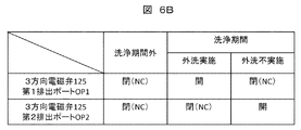
- FIG. 6A is another configuration example of the flow path switching mechanism.
- the supply port is connected to the flow path 102
- the first discharge port OP1 is connected to the cleaning tank 111
- the second discharge port OP2 is the flow path to the tank 100. It is connected to 105. Further, both the first discharge port OP1 and the second discharge port OP2 are normally closed (NC).
- FIG. 6B The operation of the solenoid valve in the flow path configuration of FIG. 6A is shown in FIG. 6B.
- both the first discharge port OP1 and the second discharge port OP2 remain closed (NC).
- the first discharge port OP1 is opened and the second discharge port OP2 is closed (NC) when the probe is externally washed, and the first discharge port OP1 is closed when the probe is not externally washed. (NC), the second discharge port OP2 is opened. Since this flow path switching mechanism can have one solenoid valve for switching the flow path, there is an advantage that the flow path configuration can be simplified.
- an electromagnetic valve is provided for each second flow path. Even when the flow path configuration of FIG. 5A or FIG. 6A is adopted, if there are a plurality of cleaning tanks, the flow path configuration shown in FIG. 5A or FIG. 6A is applied to the flow path 102 and the tank 100. It may be provided in parallel.
- the solenoid valves provided in the second flow path and the second flow path can be shared to simplify the flow path configuration.
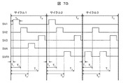
- an example of a flow path configuration in which the solenoid valve of the second flow path is shared will be described by taking the case where four cleaning tanks are present as an example.
- FIG. 7A is an example of the flow path configuration when the four cleaning tanks 111 to 114 are provided, and the cleaning operation in one cycle of the four cleaning tanks 111 to 114 is as shown in cycle 1 of the time chart shown in FIG. 7B. It shall be done. That is, the cleaning periods of the four cleaning tanks 111 to 114 do not overlap in one cycle.
- a flow path 106 (second flow path) provided with the solenoid valve SVR1 can be provided in common to the four cleaning tanks 111 to 114.
- the solenoid valve corresponding to the cleaning tank that does not perform the cleaning operation during the cleaning period of the cleaning tank when the cleaning operation is not performed in some of the four cleaning tanks 111 to 114, the solenoid valve corresponding to the cleaning tank that does not perform the cleaning operation during the cleaning period of the cleaning tank.
- cycle 2 shows an example in which the cleaning tank 113 does not perform the cleaning operation
- cycle 3 shows an example in which the cleaning tank 111 and the cleaning tank 113 do not perform the cleaning operation.
- FIG. 7A is an example in which none of the cleaning operation timings in the plurality of cleaning tanks overlap, but when the cleaning operation timings of some of the cleaning tanks overlap, the second is corresponding to the overlap of the timings.
- the flow path can be standardized and the flow path configuration can be simplified.
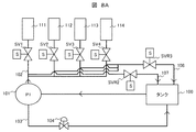
- FIG. 8A is an example of the flow path configuration when the four cleaning tanks 111 to 114 are provided, and the cleaning operation in one cycle of the four cleaning tanks 111 to 114 is as shown in cycle 1 of the time chart shown in FIG. 8B. It shall be done. That is, in one cycle, the cleaning period of the cleaning tank 111 and the cleaning tank 114 partially overlaps, and the cleaning period of the cleaning tank 112 and the cleaning tank 113 does not overlap with the cleaning period of the other cleaning tanks.
- the cleaning tanks having overlapping cleaning periods can return the cleaning water to the tank 100 from different second channels.
- a flow path 107 (second flow path) provided with the solenoid valve SVR2 is provided for the cleaning tank 111, and the solenoid valve SVR3 is commonly provided for the cleaning tank 112 to the cleaning tank 114.
- a flow path 108 (second flow path) provided with the above is provided.
- the cleaning tank 112 and the cleaning tank 113 are connected to the flow path 108, but the cleaning tanks whose cleaning periods do not overlap are connected to either the flow path 107 or the flow path 108. There is no problem.
- a solenoid valve whose opening / closing is controlled to be ON / OFF is used for cleaning water supply control, but an electromagnetic valve capable of controlling the degree of opening / closing of the valve is used for flow path switching control. Therefore, even when the timings of the cleaning operations of the cleaning tanks overlap, the flow path configuration can be simplified.
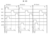
- FIG. 9A is an example of the flow path configuration when the four cleaning tanks 111 to 114 are provided, and the cleaning operation in one cycle of the four cleaning tanks 111 to 114 is performed as in cycle 1 of the time chart shown in FIG. 9B. (Same as the time chart shown in FIG. 8B).
- a flow path 109 (second flow path) provided with the solenoid valve SVP1 is provided in common to the four cleaning tanks 111 to 114, and the solenoid valve SVP1 has an opening / closing degree thereof. Is a controllable proportional control valve.
- the solenoid valves SV1 to 4 corresponding to the cleaning tanks that do not perform the cleaning operation are closed.
- the solenoid valve SVP1 is opened during the cleaning period of the cleaning tank, and the degree of opening / closing is controlled according to the overlap of the cleaning periods. For example, in the time chart of FIG.
- cycle 2 is an example in which the cleaning tank 112 and the cleaning tank 114 do not perform the cleaning operation, and during the cleaning period of the cleaning tank 112 and the cleaning tank 114, the solenoid valve SVP1 is the solenoid valve SV4 or the electromagnetic valve SV4 or the electromagnetic valve SVP1. It is opened at the opening / closing degree which is the flow rate of the valve SV2.
- cycle 3 shows an example in which the cleaning tank 111, the cleaning tank 112, and the cleaning tank 114 do not perform the cleaning operation.
- the solenoid valve SVP1 is the flow rate of the solenoid valve SV1, the solenoid valve SV4, or the solenoid valve SV2. It is opened with the degree of opening and closing. Further, in the cleaning period in which the cleaning tanks 111 and 114 overlap each other in cleaning operations, the solenoid valve SVP1 is opened with an opening / closing degree at which the flow rate of the solenoid valve SVP1 is the sum of the flow rate of the solenoid valve SV1 and the flow rate of the solenoid valve SV4.
- the present invention is not limited to the above-described embodiment, and includes various modifications.
- the solenoid valve SV1b in the cycle in which neither cleaning tank performs the cleaning operation, the solenoid valve SV1b is closed and the solenoid valve SV2b is opened during the cleaning period of the cleaning tank 13, and the cleaning tank 14 is cleaned. It is also possible to control the solenoid valve SV1b to be opened and the solenoid valve SV2b to be closed during the period because the piping pressure profile of the flow path 60 (first flow path) does not deviate from the piping pressure profile assumed in the cycle design. Is.
- Reaction disk 2 Reaction vessel 3: Cleaning mechanism 4: Spectrophotometer, 5, 6: Stirring mechanism, 7, 8: Reagent dispensing mechanism, 7a, 8a: Reagent probe, 9: Reagent disk, 10 : Reagent bottle, 11, 12: Sample dispensing mechanism, 11a, 12a: Sample probe, 13, 14, 30, 31, 32, 33: Washing tank, 15: Sample container, 16: Sample rack, 17: Sample transport mechanism , 18: Reagent syringe, 19: Sample syringe, 20: Cleaning pump, 21: Control unit, 50, 100: Tank, 51, 104: Adjustment valve, 52: Pressurized pump, 53, 54, 55, 56 , 57, 120, 121, 122, 123, 125: Electromagnetic valve, 60, 102: Flow path (first flow path), 61, 103: Return flow path, 62, 63, 105, 106, 107, 108, 109: Flow path (second flow path), 111, 112,
Abstract
Description
Claims (11)
- プローブを有し、試薬または試料を分注する分注機構と、
前記プローブの外部を洗浄水で洗浄する洗浄槽と、
洗浄水を貯留するタンクと、
前記タンクに貯留された洗浄水を第1の流路を通じて前記洗浄槽に供給するポンプと、
洗浄水を前記第1の流路を通じて前記洗浄槽に供給するか、前記第1の流路と前記タンクとの間をつなぐ第2の流路を通じて前記タンクに戻すかを切り換える流路切り換え機構と、
前記流路切り換え機構を制御する制御部とを有し、
自動分析装置のシーケンスを構成するサイクルにおいて、前記洗浄槽に前記第1の流路を通じて洗浄水を供給し、前記プローブを洗浄水で洗浄する洗浄期間が設定されており、
前記制御部は、前記プローブの洗浄を行わないサイクルにおいては、前記洗浄期間において、前記流路切り換え機構により洗浄水を前記第2の流路を通じて前記タンクに戻すよう制御する自動分析装置。 - 請求項1において、
前記流路切り換え機構は、前記第1の流路と前記洗浄槽との間に設けられた第1の2方向電磁弁と、前記第2の流路に設けられた第2の2方向電磁弁とを有し、
前記制御部は、前記洗浄期間において、前記プローブの洗浄を行うサイクルにおいては、前記第1の2方向電磁弁を開、前記第2の2方向電磁弁を閉とし、前記プローブの洗浄を行わないサイクルにおいては、前記第1の2方向電磁弁を閉、前記第2の2方向電磁弁を開とする自動分析装置。 - 請求項1において、
前記流路切り換え機構は、前記第1の流路に設けられた2方向電磁弁と、前記第1の流路が供給ポートに接続され、第1排出ポートが前記洗浄槽に接続され、第2排出ポートが前記第2の流路に接続される3方向電磁弁とを有し、
前記制御部は、前記2方向電磁弁を前記洗浄期間外においては閉とし、前記洗浄期間においては開とするとともに、前記洗浄期間において、前記プローブの洗浄を行うサイクルにおいては、前記第1排出ポートを開、前記第2排出ポートを閉とし、前記プローブの洗浄を行わないサイクルにおいては、前記第1排出ポートを閉、前記第2排出ポートを開とする自動分析装置。 - 請求項1において、
前記流路切り換え機構は、前記第1の流路が供給ポートに接続され、第1排出ポートが前記洗浄槽に接続され、第2排出ポートが前記第2の流路に接続され、前記第1排出ポート及び前記第2排出ポートともにノーマルクローズである3方向電磁弁とを有し、
前記制御部は、前記洗浄期間において、前記プローブの洗浄を行うサイクルにおいては、前記第1排出ポートを開、前記第2排出ポートを閉とし、前記プローブの洗浄を行わないサイクルにおいては、前記第1排出ポートを閉、前記第2排出ポートを開とする自動分析装置。 - 請求項1において、
複数の前記洗浄槽を有し、
複数の前記洗浄槽に対応して複数の前記第2の流路が設けられる自動分析装置。 - 請求項1において、
複数の前記洗浄槽を有し、
複数の前記洗浄槽に対応して共通に前記第2の流路が設けられており、
自動分析装置のシーケンスを構成するサイクルにおいて、前記第2の流路が共通に設けられた複数の前記洗浄槽の前記洗浄期間は重ならない自動分析装置。 - 請求項1において、
第1の洗浄槽及び第2の洗浄槽を含む複数の前記洗浄槽を有し、
自動分析装置のシーケンスを構成するサイクルにおいて、前記第1の洗浄槽の前記洗浄期間と前記第2の洗浄槽の前記洗浄期間とは重なりを有しており、
前記第1の洗浄槽に対応する前記第2の流路と、前記第2の洗浄槽に対応する前記第2の流路とは異なる自動分析装置。 - 請求項1において、
複数の前記洗浄槽を有し、
複数の前記洗浄槽に対応して前記第2の流路が共通に設けられており、
前記流路切り換え機構は、前記第2の流路に設けられ、開閉度を制御可能な電磁弁を有し、
自動分析装置のシーケンスを構成するサイクルにおいて、前記第2の流路が共通に設けられた複数の前記洗浄槽の前記洗浄期間には重なる期間を有し、
前記制御部は、前記洗浄期間に重なりを有する複数の前記洗浄槽がともに前記プローブの洗浄を行わないサイクルにおいては、前記洗浄期間の重なりに応じて前記電磁弁の開閉度を制御する自動分析装置。 - 請求項1において、
試料または試薬が分注される反応容器を洗浄する洗浄機構を有し、
前記洗浄機構は、前記タンクに貯留された洗浄水が前記第1の流路を通じて供給される自動分析装置。 - 請求項9において、
前記第1の流路からの洗浄水を加圧して前記プローブに供給する加圧ポンプを有し、
前記プローブの内部を、前記加圧ポンプにより加圧された洗浄水により洗浄する自動分析装置。 - 請求項1において、
前記ポンプと前記タンクとの間に調整弁の設けられた戻り流路を有し、前記第1の流路の圧力を調整する自動分析装置。
Priority Applications (4)
| Application Number | Priority Date | Filing Date | Title |
|---|---|---|---|
| US17/768,288 US20240012018A1 (en) | 2019-10-18 | 2020-10-07 | Automatic analyzer |
| JP2021552345A JPWO2021075324A1 (ja) | 2019-10-18 | 2020-10-07 | |
| CN202080071504.6A CN114556111A (zh) | 2019-10-18 | 2020-10-07 | 自动分析装置 |
| EP20877027.1A EP4047373A4 (en) | 2019-10-18 | 2020-10-07 | AUTOMATED ANALYZER |
Applications Claiming Priority (2)
| Application Number | Priority Date | Filing Date | Title |
|---|---|---|---|
| JP2019-191362 | 2019-10-18 | ||
| JP2019191362 | 2019-10-18 |
Publications (1)
| Publication Number | Publication Date |
|---|---|
| WO2021075324A1 true WO2021075324A1 (ja) | 2021-04-22 |
Family
ID=75537449
Family Applications (1)
| Application Number | Title | Priority Date | Filing Date |
|---|---|---|---|
| PCT/JP2020/037971 WO2021075324A1 (ja) | 2019-10-18 | 2020-10-07 | 自動分析装置 |
Country Status (5)
| Country | Link |
|---|---|
| US (1) | US20240012018A1 (ja) |
| EP (1) | EP4047373A4 (ja) |
| JP (1) | JPWO2021075324A1 (ja) |
| CN (1) | CN114556111A (ja) |
| WO (1) | WO2021075324A1 (ja) |
Citations (15)
| Publication number | Priority date | Publication date | Assignee | Title |
|---|---|---|---|---|
| JPH0136137Y2 (ja) * | 1982-10-04 | 1989-11-02 | ||
| JPH04335157A (ja) * | 1991-05-10 | 1992-11-24 | Toshiba Corp | 自動化学分析装置 |
| JPH05107252A (ja) * | 1991-10-15 | 1993-04-27 | Olympus Optical Co Ltd | 固体表面の電荷を利用した洗浄方法 |
| JPH06130072A (ja) * | 1992-10-14 | 1994-05-13 | Hitachi Ltd | 自動分析装置 |
| US5480809A (en) * | 1994-07-27 | 1996-01-02 | Mcgill University | Method and apparatus for removal of residual interfering nebulized sample |
| JPH1194839A (ja) * | 1997-09-18 | 1999-04-09 | Hitachi Ltd | 自動分析装置 |
| JP3128793U (ja) * | 2006-11-06 | 2007-01-25 | 株式会社島津製作所 | 分注装置 |
| JP2009080035A (ja) * | 2007-09-26 | 2009-04-16 | Olympus Corp | 分析装置 |
| JP2011007524A (ja) * | 2009-06-23 | 2011-01-13 | Beckman Coulter Inc | 自動分析装置および自動分析装置の精製水管理方法 |
| JP2012173059A (ja) * | 2011-02-18 | 2012-09-10 | Hitachi High-Technologies Corp | 分析装置 |
| JP2016121923A (ja) | 2014-12-24 | 2016-07-07 | 株式会社東芝 | 自動分析装置 |
| JP2017096763A (ja) * | 2015-11-24 | 2017-06-01 | 東芝メディカルシステムズ株式会社 | 自動分析装置 |
| JP2017133970A (ja) * | 2016-01-28 | 2017-08-03 | 東芝メディカルシステムズ株式会社 | 自動分析装置 |
| WO2017141627A1 (ja) * | 2016-02-19 | 2017-08-24 | 株式会社日立ハイテクノロジーズ | 自動分析装置および分注プローブの洗浄方法 |
| WO2018055931A1 (ja) * | 2016-09-23 | 2018-03-29 | 株式会社日立ハイテクノロジーズ | 自動分析装置 |
Family Cites Families (2)
| Publication number | Priority date | Publication date | Assignee | Title |
|---|---|---|---|---|
| JPH0259673A (ja) * | 1988-08-26 | 1990-02-28 | Hitachi Ltd | サンプリング装置 |
| JP2009162622A (ja) * | 2008-01-07 | 2009-07-23 | Olympus Corp | 分析装置および管理方法 |
-
2020
- 2020-10-07 US US17/768,288 patent/US20240012018A1/en active Pending
- 2020-10-07 JP JP2021552345A patent/JPWO2021075324A1/ja active Pending
- 2020-10-07 CN CN202080071504.6A patent/CN114556111A/zh active Pending
- 2020-10-07 EP EP20877027.1A patent/EP4047373A4/en active Pending
- 2020-10-07 WO PCT/JP2020/037971 patent/WO2021075324A1/ja active Application Filing
Patent Citations (15)
| Publication number | Priority date | Publication date | Assignee | Title |
|---|---|---|---|---|
| JPH0136137Y2 (ja) * | 1982-10-04 | 1989-11-02 | ||
| JPH04335157A (ja) * | 1991-05-10 | 1992-11-24 | Toshiba Corp | 自動化学分析装置 |
| JPH05107252A (ja) * | 1991-10-15 | 1993-04-27 | Olympus Optical Co Ltd | 固体表面の電荷を利用した洗浄方法 |
| JPH06130072A (ja) * | 1992-10-14 | 1994-05-13 | Hitachi Ltd | 自動分析装置 |
| US5480809A (en) * | 1994-07-27 | 1996-01-02 | Mcgill University | Method and apparatus for removal of residual interfering nebulized sample |
| JPH1194839A (ja) * | 1997-09-18 | 1999-04-09 | Hitachi Ltd | 自動分析装置 |
| JP3128793U (ja) * | 2006-11-06 | 2007-01-25 | 株式会社島津製作所 | 分注装置 |
| JP2009080035A (ja) * | 2007-09-26 | 2009-04-16 | Olympus Corp | 分析装置 |
| JP2011007524A (ja) * | 2009-06-23 | 2011-01-13 | Beckman Coulter Inc | 自動分析装置および自動分析装置の精製水管理方法 |
| JP2012173059A (ja) * | 2011-02-18 | 2012-09-10 | Hitachi High-Technologies Corp | 分析装置 |
| JP2016121923A (ja) | 2014-12-24 | 2016-07-07 | 株式会社東芝 | 自動分析装置 |
| JP2017096763A (ja) * | 2015-11-24 | 2017-06-01 | 東芝メディカルシステムズ株式会社 | 自動分析装置 |
| JP2017133970A (ja) * | 2016-01-28 | 2017-08-03 | 東芝メディカルシステムズ株式会社 | 自動分析装置 |
| WO2017141627A1 (ja) * | 2016-02-19 | 2017-08-24 | 株式会社日立ハイテクノロジーズ | 自動分析装置および分注プローブの洗浄方法 |
| WO2018055931A1 (ja) * | 2016-09-23 | 2018-03-29 | 株式会社日立ハイテクノロジーズ | 自動分析装置 |
Non-Patent Citations (1)
| Title |
|---|
| See also references of EP4047373A4 |
Also Published As
| Publication number | Publication date |
|---|---|
| CN114556111A (zh) | 2022-05-27 |
| EP4047373A4 (en) | 2023-11-22 |
| JPWO2021075324A1 (ja) | 2021-04-22 |
| EP4047373A1 (en) | 2022-08-24 |
| US20240012018A1 (en) | 2024-01-11 |
Similar Documents
| Publication | Publication Date | Title |
|---|---|---|
| US9897622B2 (en) | Automatic analyzer | |
| US11131682B2 (en) | Automatic analyzer | |
| JP6202742B2 (ja) | 自動分析装置 | |
| US20080102528A1 (en) | Automatic biochemical analyzing method and apparatus | |
| US8834637B2 (en) | Biochemical analyzer and method for cleaning fluid components of the same | |
| US11506678B2 (en) | Automatic analysis apparatus and operating method therefor | |
| US8734721B2 (en) | Analyzer | |
| CN101135694A (zh) | 自动分析装置 | |
| WO2017141627A1 (ja) | 自動分析装置および分注プローブの洗浄方法 | |
| US20180128847A1 (en) | Automatic analyzer | |
| US20140037503A1 (en) | Automatic analyzer | |
| JP7455142B2 (ja) | 自動分析装置 | |
| WO2021075324A1 (ja) | 自動分析装置 | |
| JP2011033426A (ja) | 自動分析装置および自動分析装置の制御方法 | |
| JP2014206380A (ja) | 自動分析装置 | |
| JP2010071897A (ja) | 自動分析装置 | |
| JP2016211879A (ja) | 自動分析装置 | |
| WO2021005835A1 (ja) | 自動分析装置、および自動分析装置の運転方法 | |
| JP2008304334A (ja) | 分注装置及び自動分析装置 | |
| WO2022004064A1 (ja) | 自動分析装置 | |
| JP6355960B2 (ja) | 臨床検査装置及び容器の洗浄方法 | |
| JP6877629B2 (ja) | 自動分析装置および自動分析装置の流路詰まり検出方法 | |
| JPH10104240A (ja) | 生化学自動分析装置のプローブ洗浄機構 | |
| WO2023119835A1 (ja) | 自動分析装置 | |
| CN220773079U (zh) | 一种样本分析仪和液路支持机构 |
Legal Events
| Date | Code | Title | Description |
|---|---|---|---|
| 121 | Ep: the epo has been informed by wipo that ep was designated in this application |
Ref document number: 20877027 Country of ref document: EP Kind code of ref document: A1 |
|
| WWE | Wipo information: entry into national phase |
Ref document number: 17768288 Country of ref document: US |
|
| ENP | Entry into the national phase |
Ref document number: 2021552345 Country of ref document: JP Kind code of ref document: A |
|
| NENP | Non-entry into the national phase |
Ref country code: DE |
|
| ENP | Entry into the national phase |
Ref document number: 2020877027 Country of ref document: EP Effective date: 20220518 |