WO2021065236A1 - 基板ホルダ及び基板処理装置 - Google Patents
基板ホルダ及び基板処理装置 Download PDFInfo
- Publication number
- WO2021065236A1 WO2021065236A1 PCT/JP2020/031380 JP2020031380W WO2021065236A1 WO 2021065236 A1 WO2021065236 A1 WO 2021065236A1 JP 2020031380 W JP2020031380 W JP 2020031380W WO 2021065236 A1 WO2021065236 A1 WO 2021065236A1
- Authority
- WO
- WIPO (PCT)
- Prior art keywords
- substrate
- moving member
- contact
- positioning
- ideal axis
- Prior art date
- Legal status (The legal status is an assumption and is not a legal conclusion. Google has not performed a legal analysis and makes no representation as to the accuracy of the status listed.)
- Ceased
Links
Images









Classifications
-
- C—CHEMISTRY; METALLURGY
- C25—ELECTROLYTIC OR ELECTROPHORETIC PROCESSES; APPARATUS THEREFOR
- C25D—PROCESSES FOR THE ELECTROLYTIC OR ELECTROPHORETIC PRODUCTION OF COATINGS; ELECTROFORMING; APPARATUS THEREFOR
- C25D17/00—Constructional parts, or assemblies thereof, of cells for electrolytic coating
- C25D17/06—Suspending or supporting devices for articles to be coated
- C25D17/08—Supporting racks, i.e. not for suspending
-
- C—CHEMISTRY; METALLURGY
- C25—ELECTROLYTIC OR ELECTROPHORETIC PROCESSES; APPARATUS THEREFOR
- C25D—PROCESSES FOR THE ELECTROLYTIC OR ELECTROPHORETIC PRODUCTION OF COATINGS; ELECTROFORMING; APPARATUS THEREFOR
- C25D17/00—Constructional parts, or assemblies thereof, of cells for electrolytic coating
- C25D17/06—Suspending or supporting devices for articles to be coated
-
- C—CHEMISTRY; METALLURGY
- C23—COATING METALLIC MATERIAL; COATING MATERIAL WITH METALLIC MATERIAL; CHEMICAL SURFACE TREATMENT; DIFFUSION TREATMENT OF METALLIC MATERIAL; COATING BY VACUUM EVAPORATION, BY SPUTTERING, BY ION IMPLANTATION OR BY CHEMICAL VAPOUR DEPOSITION, IN GENERAL; INHIBITING CORROSION OF METALLIC MATERIAL OR INCRUSTATION IN GENERAL
- C23C—COATING METALLIC MATERIAL; COATING MATERIAL WITH METALLIC MATERIAL; SURFACE TREATMENT OF METALLIC MATERIAL BY DIFFUSION INTO THE SURFACE, BY CHEMICAL CONVERSION OR SUBSTITUTION; COATING BY VACUUM EVAPORATION, BY SPUTTERING, BY ION IMPLANTATION OR BY CHEMICAL VAPOUR DEPOSITION, IN GENERAL
- C23C18/00—Chemical coating by decomposition of either liquid compounds or solutions of the coating forming compounds, without leaving reaction products of surface material in the coating; Contact plating
- C23C18/16—Chemical coating by decomposition of either liquid compounds or solutions of the coating forming compounds, without leaving reaction products of surface material in the coating; Contact plating by reduction or substitution, e.g. electroless plating
- C23C18/1601—Process or apparatus
- C23C18/1619—Apparatus for electroless plating
- C23C18/1628—Specific elements or parts of the apparatus
- C23C18/163—Supporting devices for articles to be coated
-
- C—CHEMISTRY; METALLURGY
- C23—COATING METALLIC MATERIAL; COATING MATERIAL WITH METALLIC MATERIAL; CHEMICAL SURFACE TREATMENT; DIFFUSION TREATMENT OF METALLIC MATERIAL; COATING BY VACUUM EVAPORATION, BY SPUTTERING, BY ION IMPLANTATION OR BY CHEMICAL VAPOUR DEPOSITION, IN GENERAL; INHIBITING CORROSION OF METALLIC MATERIAL OR INCRUSTATION IN GENERAL
- C23C—COATING METALLIC MATERIAL; COATING MATERIAL WITH METALLIC MATERIAL; SURFACE TREATMENT OF METALLIC MATERIAL BY DIFFUSION INTO THE SURFACE, BY CHEMICAL CONVERSION OR SUBSTITUTION; COATING BY VACUUM EVAPORATION, BY SPUTTERING, BY ION IMPLANTATION OR BY CHEMICAL VAPOUR DEPOSITION, IN GENERAL
- C23C18/00—Chemical coating by decomposition of either liquid compounds or solutions of the coating forming compounds, without leaving reaction products of surface material in the coating; Contact plating
- C23C18/16—Chemical coating by decomposition of either liquid compounds or solutions of the coating forming compounds, without leaving reaction products of surface material in the coating; Contact plating by reduction or substitution, e.g. electroless plating
- C23C18/1601—Process or apparatus
- C23C18/1619—Apparatus for electroless plating
- C23C18/1632—Features specific for the apparatus, e.g. layout of cells and of its equipment, multiple cells
-
- C—CHEMISTRY; METALLURGY
- C25—ELECTROLYTIC OR ELECTROPHORETIC PROCESSES; APPARATUS THEREFOR
- C25D—PROCESSES FOR THE ELECTROLYTIC OR ELECTROPHORETIC PRODUCTION OF COATINGS; ELECTROFORMING; APPARATUS THEREFOR
- C25D17/00—Constructional parts, or assemblies thereof, of cells for electrolytic coating
-
- C—CHEMISTRY; METALLURGY
- C25—ELECTROLYTIC OR ELECTROPHORETIC PROCESSES; APPARATUS THEREFOR
- C25D—PROCESSES FOR THE ELECTROLYTIC OR ELECTROPHORETIC PRODUCTION OF COATINGS; ELECTROFORMING; APPARATUS THEREFOR
- C25D17/00—Constructional parts, or assemblies thereof, of cells for electrolytic coating
- C25D17/001—Apparatus specially adapted for electrolytic coating of wafers, e.g. semiconductors or solar cells
-
- C—CHEMISTRY; METALLURGY
- C25—ELECTROLYTIC OR ELECTROPHORETIC PROCESSES; APPARATUS THEREFOR
- C25D—PROCESSES FOR THE ELECTROLYTIC OR ELECTROPHORETIC PRODUCTION OF COATINGS; ELECTROFORMING; APPARATUS THEREFOR
- C25D7/00—Electroplating characterised by the article coated
-
- C—CHEMISTRY; METALLURGY
- C25—ELECTROLYTIC OR ELECTROPHORETIC PROCESSES; APPARATUS THEREFOR
- C25D—PROCESSES FOR THE ELECTROLYTIC OR ELECTROPHORETIC PRODUCTION OF COATINGS; ELECTROFORMING; APPARATUS THEREFOR
- C25D7/00—Electroplating characterised by the article coated
- C25D7/12—Semiconductors
-
- H—ELECTRICITY
- H10—SEMICONDUCTOR DEVICES; ELECTRIC SOLID-STATE DEVICES NOT OTHERWISE PROVIDED FOR
- H10P—GENERIC PROCESSES OR APPARATUS FOR THE MANUFACTURE OR TREATMENT OF DEVICES COVERED BY CLASS H10
- H10P72/00—Handling or holding of wafers, substrates or devices during manufacture or treatment thereof
- H10P72/04—Apparatus for manufacture or treatment
- H10P72/0451—Apparatus for manufacturing or treating in a plurality of work-stations
- H10P72/0452—Apparatus for manufacturing or treating in a plurality of work-stations characterised by the layout of the process chambers
- H10P72/0456—Apparatus for manufacturing or treating in a plurality of work-stations characterised by the layout of the process chambers in-line arrangement
-
- H—ELECTRICITY
- H10—SEMICONDUCTOR DEVICES; ELECTRIC SOLID-STATE DEVICES NOT OTHERWISE PROVIDED FOR
- H10P—GENERIC PROCESSES OR APPARATUS FOR THE MANUFACTURE OR TREATMENT OF DEVICES COVERED BY CLASS H10
- H10P72/00—Handling or holding of wafers, substrates or devices during manufacture or treatment thereof
- H10P72/04—Apparatus for manufacture or treatment
- H10P72/0451—Apparatus for manufacturing or treating in a plurality of work-stations
- H10P72/0468—Apparatus for manufacturing or treating in a plurality of work-stations comprising a chamber adapted to a particular process
- H10P72/0476—Apparatus for manufacturing or treating in a plurality of work-stations comprising a chamber adapted to a particular process comprising at least one plating chamber
-
- H—ELECTRICITY
- H10—SEMICONDUCTOR DEVICES; ELECTRIC SOLID-STATE DEVICES NOT OTHERWISE PROVIDED FOR
- H10P—GENERIC PROCESSES OR APPARATUS FOR THE MANUFACTURE OR TREATMENT OF DEVICES COVERED BY CLASS H10
- H10P72/00—Handling or holding of wafers, substrates or devices during manufacture or treatment thereof
- H10P72/30—Handling or holding of wafers, substrates or devices during manufacture or treatment thereof for conveying, e.g. between different workstations
- H10P72/33—Handling or holding of wafers, substrates or devices during manufacture or treatment thereof for conveying, e.g. between different workstations into and out of processing chamber
- H10P72/3308—Vertical transfer of a single workpiece
-
- H—ELECTRICITY
- H10—SEMICONDUCTOR DEVICES; ELECTRIC SOLID-STATE DEVICES NOT OTHERWISE PROVIDED FOR
- H10P—GENERIC PROCESSES OR APPARATUS FOR THE MANUFACTURE OR TREATMENT OF DEVICES COVERED BY CLASS H10
- H10P72/00—Handling or holding of wafers, substrates or devices during manufacture or treatment thereof
- H10P72/70—Handling or holding of wafers, substrates or devices during manufacture or treatment thereof for supporting or gripping
- H10P72/76—Handling or holding of wafers, substrates or devices during manufacture or treatment thereof for supporting or gripping using mechanical means, e.g. clamps or pinches
- H10P72/7602—Handling or holding of wafers, substrates or devices during manufacture or treatment thereof for supporting or gripping using mechanical means, e.g. clamps or pinches the wafers being placed on a robot blade or gripped by a gripper for conveyance
-
- H—ELECTRICITY
- H10—SEMICONDUCTOR DEVICES; ELECTRIC SOLID-STATE DEVICES NOT OTHERWISE PROVIDED FOR
- H10P—GENERIC PROCESSES OR APPARATUS FOR THE MANUFACTURE OR TREATMENT OF DEVICES COVERED BY CLASS H10
- H10P72/00—Handling or holding of wafers, substrates or devices during manufacture or treatment thereof
- H10P72/70—Handling or holding of wafers, substrates or devices during manufacture or treatment thereof for supporting or gripping
- H10P72/76—Handling or holding of wafers, substrates or devices during manufacture or treatment thereof for supporting or gripping using mechanical means, e.g. clamps or pinches
- H10P72/7604—Handling or holding of wafers, substrates or devices during manufacture or treatment thereof for supporting or gripping using mechanical means, e.g. clamps or pinches the wafers being placed on a susceptor, stage or support
- H10P72/7606—Handling or holding of wafers, substrates or devices during manufacture or treatment thereof for supporting or gripping using mechanical means, e.g. clamps or pinches the wafers being placed on a susceptor, stage or support characterised by edge clamping, e.g. clamping ring
-
- H—ELECTRICITY
- H10—SEMICONDUCTOR DEVICES; ELECTRIC SOLID-STATE DEVICES NOT OTHERWISE PROVIDED FOR
- H10P—GENERIC PROCESSES OR APPARATUS FOR THE MANUFACTURE OR TREATMENT OF DEVICES COVERED BY CLASS H10
- H10P72/00—Handling or holding of wafers, substrates or devices during manufacture or treatment thereof
- H10P72/70—Handling or holding of wafers, substrates or devices during manufacture or treatment thereof for supporting or gripping
- H10P72/76—Handling or holding of wafers, substrates or devices during manufacture or treatment thereof for supporting or gripping using mechanical means, e.g. clamps or pinches
- H10P72/7604—Handling or holding of wafers, substrates or devices during manufacture or treatment thereof for supporting or gripping using mechanical means, e.g. clamps or pinches the wafers being placed on a susceptor, stage or support
- H10P72/7608—Handling or holding of wafers, substrates or devices during manufacture or treatment thereof for supporting or gripping using mechanical means, e.g. clamps or pinches the wafers being placed on a susceptor, stage or support characterised by a plurality of separate clamping members, e.g. clamping fingers
-
- H—ELECTRICITY
- H10—SEMICONDUCTOR DEVICES; ELECTRIC SOLID-STATE DEVICES NOT OTHERWISE PROVIDED FOR
- H10P—GENERIC PROCESSES OR APPARATUS FOR THE MANUFACTURE OR TREATMENT OF DEVICES COVERED BY CLASS H10
- H10P72/00—Handling or holding of wafers, substrates or devices during manufacture or treatment thereof
- H10P72/70—Handling or holding of wafers, substrates or devices during manufacture or treatment thereof for supporting or gripping
- H10P72/78—Handling or holding of wafers, substrates or devices during manufacture or treatment thereof for supporting or gripping using vacuum or suction, e.g. Bernoulli chucks
Definitions
- the present invention relates to a substrate holder and a substrate processing apparatus.
- a plating device is used to form a metal thin film on the surface of the substrate.
- a substrate holder that holds a substrate such as a semiconductor wafer in a detachable manner may be used. Then, in the plating apparatus, the substrate held in the substrate holder is immersed in the plating solution, and a voltage is applied to the substrate to plate the surface of the substrate.
- Patent Document 1 An example of a substrate holder is described in Patent Document 1.
- a first holding member having a first surface configured to be in contact with a substrate and a second holding member that sandwiches and holds the substrate together with the first holding member.
- a substrate holder having the above is disclosed.
- the first holding member of the substrate holder has a positioning member for positioning the substrate in contact with the first surface at a predetermined position on the first surface.
- the positioning member has a first position that contacts the peripheral edge of the substrate and positions the substrate at a predetermined position on the first surface, and a second position that is located outside the peripheral edge of the substrate and does not contact the substrate. It is configured to move between.
- the second holding member has a driving member configured to position the positioning member at the first position when the substrate is held by the first holding member and the second holding member.
- the positioning member has a tip portion.
- the tip portion is branched into a first tip portion and a second tip portion, and a space is generated between the first tip portion and the second tip portion.
- the first tip portion is located inside the radial direction of the substrate, and the second tip portion is located outside the radial direction of the substrate.
- the first tip portion is configured to be in contact with the substrate, and the second tip portion is configured to be in contact with the drive member.
- the driving member comes into contact with the second tip portion and moves the positioning member to the first position. be able to.
- the substrate holder can position the substrate.
- the first tip portion has some elasticity and can come into contact with the substrate, and even if the substrates differ in size by several mm, the first tip portion absorbs the dimensional difference of several mm. Substrates of different sizes can be positioned by the positioning member.
- Patent Document 2 discloses a substrate holder having a movable holding member and a fixed holding member, as shown in FIG.
- the substrate holder uses a plurality of leaf spring members having spring properties that elastically contact the outer peripheral end surface of the substrate to position the substrate as the movable holding member. It is characterized by being provided.
- the substrate holder described in Patent Document 2 in the process of holding the substrate, the substrate is urged inward by the elastic force of the leaf spring member having a spring property, and the substrate is urged inward through the leaf spring member. Can be positioned (centered) with respect to the board holder.
- Patent Document 2 describes that a plurality of elastic leaf spring members (positioning members) are arranged to position the substrate.
- the leaf spring members having elasticity individually press against each other in the presence of frictional force between the substrate and the support surface, and as a result, the amount of deformation of the leaf spring members is the same. That is, there is a problem that the holding of the substrate is completed while the positioning accuracy of the substrate is insufficient.
- Patent Document 2 since the space between the first tip portion and the second tip portion has the same function as the leaf spring member described in Patent Document 2, Patent Document 2 It has basically the same problem as the board holder described in.
- an object of the present invention is to provide a substrate holder and a substrate processing apparatus capable of positioning the substrate even when the substrate receives frictional force or the like from a support surface.
- the substrate holder according to the present invention has a support surface for supporting the substrate, and positions the substrate so that the central axis of the substrate is positioned on an ideal axis extending in a direction perpendicular to the support surface.
- Three or more substrate holders having a first holding member, a second holding member for sandwiching the substrate together with the first holding member, and a contact surface for contacting a side end portion of the substrate.
- a first moving member having a plurality of engaging portions to be engaged and a first urging member for urging the first moving member are provided, and the first moving member is an urging of the first urging member.
- the force is transmitted to each of the positioning members via the engaging portion, and the contact surface of each of the positioning members approaches the ideal axis due to the urging force transmitted from the first urging member. Being urged in the direction.
- each positioning member is urged in a direction in which the contact surface approaches the ideal axis. Therefore, when the substrate is placed on the support surface, the contact surface of the positioning member comes into contact with the side end portion of the substrate and pushes the substrate in the direction of the ideal axis. As a result, the three or more positioning members position the substrate so as to sandwich the substrate from the surroundings. At this time, the first moving member maintains a state in which the distance between the ideal axis and the contact surface of each positioning member is equal. Therefore, if the substrate is circular, the three or more positioning members can position the center of the sandwiched substrate on the ideal axis.
- this substrate holder can position the substrate even when the substrate receives frictional force or the like from the support surface.
- FIG. 5 is a cross-sectional view taken along the line AA of FIG. 5 when the positioning member is located at the first position.
- FIG. 5 is a cross-sectional view taken along the line AA of FIG.
- (A) is a schematic view of a DD cross section of FIG. 3 in a state where the second member is in the process of closing
- (b) is a sectional view taken along the line FF of (a).
- It is the schematic which shows the modification of the substrate holder shown in FIG. It is the schematic which shows another modification of the substrate holder shown in FIG.
- It is the schematic which shows another modification of the substrate holder shown in FIG. It is the schematic which shows another modification of the substrate holder shown in FIG.
- FIG. shows another modification of the substrate holder shown in FIG.
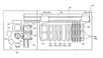
- FIG. 1 is an overall layout diagram of a plating apparatus 100 that performs a plating process using the substrate holder 200 according to the first embodiment.
- the plating apparatus 100 includes two cassette tables 102, an aligner 104, a spin rinse dryer 106, a substrate transfer apparatus 108, and a substrate attachment / detachment portion 120.
- the plating apparatus 100 is, for example, a wet and vertical type electrolytic plating apparatus, but may be a horizontal type, a dry type electrolytic plating apparatus, or an electroless plating apparatus. Further, as an example, the plating apparatus 100 performs plating on a circular substrate W.
- the cassette table 102 has a function of mounting a cassette 103 containing a substrate W such as a semiconductor wafer.
- the spin rinse dryer 106 has a function of rotating the substrate W after the plating treatment at high speed to dry it.
- the substrate attachment / detachment portion 120 has two mounting plates 122. In the board attachment / detachment portion 120, the substrate W is attached / detached to / from the substrate holder 200 mounted on the mounting plate 122.
- the board transfer device 108 is arranged at the center of the cassette table 102, the aligner 104, the spin rinse dryer 106, and the board attachment / detachment portion 120.
- the substrate transfer device 108 has a function of transferring the substrate W between the cassette table 102, the aligner 104, the spin rinse dryer 106, and the substrate attachment / detachment portion 120.
- the substrate transfer device 108 is composed of a transfer robot.
- the plating apparatus 100 further includes a stocker 124, a pre-wet tank 126, a pre-soak tank 128, a first cleaning tank 130a, a blow tank 132, a second cleaning tank 130b, and a plating unit 160.
- the substrate holder 200 is stored and temporarily placed.
- the pre-wet tank 126 holds pure water.
- the pre-wet tank 126 improves the hydrophilicity of the substrate W by immersing the substrate W in pure water to wet the surface.
- the pre-soak tank 128 holds sulfuric acid.
- the pre-soak tank 128 has a function of etching and removing an oxide film on the surface of a conductive layer such as a seed layer formed on the surface of the substrate W with sulfuric acid.
- the first cleaning tank 130a holds a cleaning liquid (pure water or the like).
- the substrate W after pre-soaking can be cleaned together with the substrate holder 200 with a cleaning liquid (pure water or the like).
- the blow tank 132 has a function of draining the substrate W after cleaning.
- the second cleaning tank 130b has a function of cleaning the plated substrate W together with the substrate holder 200 with a cleaning liquid.
- the plating unit 160 includes a plurality of adjacent plating tanks 162 and an overflow tank 164 that surrounds the outer periphery of the plurality of plating tanks 162.
- each plating tank 162 is configured such that one substrate W is housed inside, the substrate W is immersed in a plating solution held inside, and the surface of the substrate W is plated with copper plating or the like. ing.
- the pre-wet tank 126, the pre-soak tank 128, the first cleaning tank 130a, the blow tank 132, the second cleaning tank 130b, and the plating tank 162 can be referred to as a treatment tank 180. That is, the processing tank 180 is a tank for processing the substrate W.
- the plating device 100 further includes a substrate holder transfer device 190.
- the substrate holder transfer device 190 includes a horizontal rail 192, a first transporter 194a, and a second transporter 194b.
- the first transporter 194a and the second transporter 194b have the same structure, and can be simply referred to as transporters 194, respectively.
- the substrate holder transfer device 190 includes a linearly arranged substrate attachment / detachment portion 120, a stocker 124, a pre-wet tank 126, a pre-soak tank 128, a first cleaning tank 130a, a blow tank 132, a second cleaning tank 130b, and a plating unit 160. Located on the side.
- the substrate holder transfer device 190 employs a linear motor system.
- the horizontal rail 192 extends linearly adjacent to each of the processing tanks 180 arranged in a straight line.
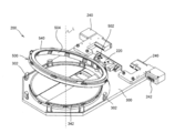
- FIG. 2 is a perspective view of the substrate holder 200.
- the substrate holder 200 includes a first member 300 (an example of a first holding member), a second member 500 (an example of a second holding member), a hinge 220, and a pair of hands 240.
- the second member 500 has a seal holder 540 having an annular shape and a flat plate-shaped base 502 extending from the seal holder 540 to the hinge 220 and supported by the hinge 220. Further, the hinge 220 connects the second member 500 and the first member 300.
- the second member 500 is rotatably configured with the hinge 220 as a fulcrum. Then, when the second member 500 is rotated and closed, the substrate holder 200 can sandwich the substrate W between the first member 300 and the second member 500. That is, the substrate holder 200 has a function of holding the substrate W.
- An opening 504 is formed in the second member 500. The opening 504 is slightly smaller than the size of the substrate W.
- the substrate W is sandwiched between the first member 300 and the second member 500, the surface to be processed of the substrate W is exposed through the opening 504. That is, when the substrate holder 200 is held in the processing tank 180, the processing liquid in the processing tank 180 can come into contact with the exposed surface to be processed of the substrate W. As a result, the surface to be processed of the substrate W is treated.
- each hand 240 has a T-shape and serves as a support portion for transporting or suspending and supporting the substrate holder 200.
- the transporter 194 can grip the hand 240 and conveys the substrate holder 200 while holding the hand 240.
- one hand 240 is provided with an external contact portion 242 that is electrically connected to an external power source.
- the external contact portion 242 is electrically connected to a plurality of conductive members 306 (see FIGS. 3 and 4) provided on the outer periphery of the base 340 via a plurality of conducting wires.
- FIG. 3 is a schematic view of the substrate holder 200 as viewed from the front direction
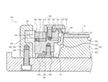
- FIG. 4 is a partially enlarged view of the cut surface of the substrate holder 200 in the thickness direction while holding the substrate W.
- the first member 300 further includes a plurality of clampers 302, fasteners 304, first support base 320, second support base 330, base 340, and conductive member 306.
- the second member 500 includes a pressing ring 506, a spacer 512, a first fixing ring 514, a second fixing ring 516, a substrate seal member 518, a holder seal member 520, a fastener 522, a fastener 524, a contact member 526, and fastening. It also has a tool 528.
- the seal holder 540 is made of vinyl chloride as an example. Further, an annular first fixing ring 514 is attached to the seal holder 540 by a fastener 522. The annular substrate seal member 518 is sandwiched between the seal holder 540 and the first fixing ring 514. Further, an annular second fixing ring 516 is attached to the seal holder 540 by a fastener 524. The annular holder seal member 520 is sandwiched between the seal holder 540 and the second fixing ring 516. That is, the substrate seal member 518 and the holder seal member 520 are attached to the seal holder 540. In the substrate holder 200, as an example, the centers of the seal holder 540, the substrate seal member 518, and the holder seal member 520 are located on the central axis L as an example.
- the substrate seal member 518 comes into contact with the vicinity of the outer peripheral portion of the surface of the substrate W. As a result, the substrate sealing member 518 has a function of sealing the gap between the substrate W and the second member 500.
- the holder seal member 520 comes into contact with the first member 300 when the substrate holder 200 holds the substrate W. As a result, the holder seal member 520 has a function of sealing the gap between the first member 300 and the second member 500. Therefore, when the substrate W is held by the substrate holder 200, as shown in FIG. 4, an internal space R1 sealed by the substrate seal member 518 and the holder seal member 520 is formed inside the substrate holder 200.
- the plurality of clampers 302 have a function of engaging with the protrusion 508, which will be described later, and fixing the second member 500 to the first member 300 together with the protrusion 508.
- the clamper 302 has an inverted L shape and has a protruding portion 303 projecting in the direction of the support surface 342. Further, the clampers 302 are arranged at substantially equal intervals along the periphery of the support surface 342 (see FIG. 3), and each clamper 302 is fixed to the first support base 320 by a fastener 304.
- the seal holder 540 is formed with a step portion 542 on the outer peripheral portion.
- a pressing ring 506 is rotatably attached to the step portion 542 via a spacer 512.
- the presser ring 506 is made of a metal (for example, titanium) having excellent corrosion resistance against acid and having sufficient rigidity.
- the spacer 512 is made of a material having a low coefficient of friction so that the presser ring 506 can rotate smoothly.
- the spacer 512 is made of PTFE (polytetrafluoroethylene) as an example.
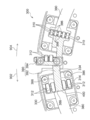
- FIG. 5 is a front view of the portion of the first member 300 of the substrate holder 200.
- the first member 300 further includes six positioning members 360 arranged so as to surround the support surface 342.
- the substrate holder 200 has a function of positioning the substrate W with respect to the substrate holder 200 by using the positioning member 360 by a method described later.
- positioning means moving the substrate W to a position where the center of the substrate W is located on the ideal axis.
- the ideal axis is a straight line that passes through the point where the center of the substrate W should be located in the substrate holder 200 and is perpendicular to the support surface 342. Further, in the present embodiment, the ideal axis coincides with the central axis L. Therefore, when the ideal axis shows the straight line L in the figure, it is described as the ideal axis L.
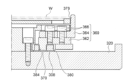
- the positioning member 360 is, for example, a substantially L-shaped member, and has a support member 362, an L-shaped member 364, and two fasteners 366.
- the support member 362 is a rectangular parallelepiped block-shaped member, and a groove 368 extending linearly in the longitudinal direction is formed. Further, the support member 362 has a pin 370 (an example of the engaged portion 370) extending in parallel with the ideal axis L on the surface opposite to the surface on which the groove 368 is formed.
- the L-shaped member 364 is a substantially L-shaped member, and has a fixed portion 372 and a tip portion 374 extending substantially orthogonal to the fixed portion 372 and extending above the support surface 342.
- the L-shaped member 364 is fixed to the support member 362 by two fasteners 366 in a state where the fixed portion 372 is fitted into the groove 368 of the support member 362. Further, the tip portion 374 comes into contact with the substrate W when positioning the substrate W.
- the surface that comes into contact with the substrate W is called a contact surface 376.
- the positioning member 360 has a contact surface 376 for contacting the side end portion of the substrate W.
- the second support base 330 is formed with a linear groove 332 extending in the radial direction of a virtual circle VC (see FIG. 5) centered on the ideal axis L.
- the positioning member 360 is fitted in the groove 332.
- the positioning member 360 can move along the groove 332. More specifically, the positioning member 360 is a second position in which the positioning member 360 is closer to the ideal axis L than the first position shown in FIG. 7 from the first position away from the ideal axis L shown in FIG. Can be moved to.
- the distance between the ideal axis L and the contact surface 376 when the positioning member 360 is in the first position is longer than the radius of the substrate W, and the ideal axis L when the positioning member 360 is in the second position.
- the distance between the contact surface 376 and the contact surface 376 is shorter than the radius of the substrate W.
- first member 300 further has a seat 308 located between the first moving member 380 and the first support base 320, which will be described later (see FIG. 6).
- Sheet 308 is made of Teflon® as an example.
- FIG. 9 is a partial cross-sectional view of the substrate holder 200 as viewed from the rear direction. Inside the cross-sectional line 900 of FIG. 9, the first support base 320 is omitted.
- FIG. 10 is an enlarged view of a portion B of FIG. The direction indicated by the arrow 902 in FIG. 9 is defined as the first rotation direction 902, and the rotation direction opposite to the first rotation direction 902 is defined as the second rotation direction 904.
- the first member 300 further includes a first moving member 380.
- the first moving member 380 is, for example, an arc-shaped member.
- the first moving member 380 has a pair of side surfaces 382 extending in the circumferential direction of the virtual circle VC centered on the ideal axis L.
- the second support base 330 is formed with an arcuate groove 334 centered on the ideal axis L.
- the second support base 330 has a plurality of guide members 336.
- the guide member 336 has a function of contacting each side surface 382 of the first moving member 380 and guiding the first moving member 380 in the circumferential direction of the virtual circle VC centered on the ideal axis L. Therefore, the first moving member 380 is guided by a plurality of guide members 336 in a state of being fitted in the groove 334. That is, the first moving member 380 is configured to be rotatable about the ideal axis L.
- the first moving member 380 rotates, a plurality of elongated holes 384 move all at once. As a result, the first moving member 380 can operate the plurality of positioning members 360 at the same time.
- the rotation of the first moving member 380 is transmitted to the positioning member 360 via the elongated hole 384 and the pin 370, and the positioning member 360 is a virtual circle centered on the ideal axis L. Move in the radial direction of VC.
- the positioning member 360 and the first moving member 380 are configured so that the ideal axis L and the contact surface 376 of each positioning member 360 maintain the same distance when the positioning member 360 is moved. ing.
- FIG. 11 is an enlarged view of a portion C in FIG. 9, which is a view when the second moving member 390 is located at a steady position.
- the second pressed surface 388 is the second pressing surface 400.
- FIG. 12 is an enlarged view of the portion C of FIG. 9, which is a view when the second moving member 390 is located at the displacement position and the second pressed surface 388 is in contact with the second pressing surface 400.
- FIG. 13 is an enlarged view of portion C of FIG. 9, which is a view when the second moving member 390 is located at the displacement position and the second pressed surface 388 is separated from the second pressing surface 400. ..
- the guide member 314 has a function of contacting each side surface 396 of the rotating member 392 and guiding the rotating member 392 in the circumferential direction of the virtual circle VC centered on the ideal axis L.
- the second moving member 390 is configured to be rotatable about the ideal axis L. Further, the rotation of the second moving member 390 is restricted by coming into contact with the second support base 330. Therefore, the second moving member 390 can rotate from the steady position shown in FIG. 11 to the displacement position shown in FIGS. 12 and 13.
- the displacement position is, for example, a certain position when the second moving member 390 moves from the steady position to the second rotation direction 904 and stops.
- the first member 300 has a plurality of first urging members 310.
- the first urging member 310 is an elastic member, and is, for example, a spring.
- the second moving member 390 has a plurality of first pressing surfaces 398 as an example.
- the first moving member 380 has a first pressed surface 386 facing the first pressing surface 398.
- the first urging member 310 is located between the first pressed surface 386 and the first pressed surface 398, and urges the first moving member 380 in the second rotation direction 904 via the first pressed surface 386. doing. That is, the first urging member 310 is in a compressed state.
- the urging force of the first urging member 310 is applied to the positioning member 360 via the elongated hole 384 and the pin 370. Is transmitted to.
- the contact surface 376 is urged in a direction approaching the ideal axis L by the urging force transmitted from the first urging member 310 (see FIG. 9).
- the positioning member 360 moves in the radial direction of the virtual circle VC centered on the ideal axis L. That is, the first moving member 380 has a function of transmitting the urging force of the first urging member 310 to the respective positioning members 360.
- the second moving member 390 has a second pressing surface 400 as an example
- the first moving member 380 has a second pressed surface 388 facing the second pressing surface 400 as an example. ing. Then, when the first urging member 310 urges the first moving member 380, the first moving member 380 is urged so that the second pressed surface 388 faces the second pressing surface 400, and the second The pressed surface 388 is in contact with the second pressed surface 400 (see FIG. 9).
- the behavior of each component when the second moving member 390 rotates from the steady position shown in FIG. 11 in the second rotation direction 904 will be described.
- the second moving member 390 receives an external force and rotates in the second rotation direction 904 from the steady position when the substrate W is not on the base 340
- the second pressed surface 388 is as shown in FIG. It rotates together with the second pressing surface 400 without being separated.
- the first moving member 380 rotates in the same rotation direction as the second moving member 390.
- the positioning member 360 described above moves in a direction approaching the ideal axis L in conjunction with the rotation of the first moving member 380.
- the substrate W is placed on the base 340 and the second moving member 390 receives an external force and rotates from the steady position to the second rotation direction 904, the substrate W is initially placed on the base 340.
- the second pressed surface 388 rotates together with the second pressed surface 400 in the same manner as when there is no.
- the positioning member 360 moves in a direction approaching the ideal axis L in conjunction with the rotation of the first moving member 380.
- the positioning member 360 cannot move due to the reaction force from the substrate W. .. Then, the first moving member 380 cannot rotate.
- FIG. 12 was used to explain the behavior of each component in the absence of the substrate W, but the substrate W is present and the positioning member 360 is in the process of closing the second member 500.
- the state in which the positioning of the substrate W is completed is also substantially the same as the state shown in FIG. That is, to explain the ideal behavior, when the positioning of the substrate W is completed, the second pressed surface 388 and the second pressed surface 400 are in contact with each other as shown in FIG.
- the first moving member 380 and the second moving member 390 may be located at positions rotated in the first rotation direction 902, unlike the state shown in FIG. possible. This can be understood by those skilled in the art from the above description.
- the first movement is performed until the second pressed surface 388 and the second pressing surface 400 first come into contact with each other.
- the member 380 does not rotate, but the second moving member 390 rotates.
- both the first moving member 380 and the second moving member 390 rotate in the first rotation direction 902 while being in contact with each other.
- FIG. 11 when the second moving member 390 is positioned at the steady position, the second moving member 390 rotates in the first rotation direction 902 from the displacement position shown in FIG.
- the positioning member 360 moves to the first position shown in FIG.
- the second moving member 390 when the second moving member 390 rotates about the ideal axis L, the second moving member 390 can rotate the first moving member 380 about the ideal axis L. That is, the second moving member 390 has a function of rotating the first moving member 380 around the ideal axis L.
- the first member 300 has a plurality of second urging members 312 as an example.
- the second urging member 312 is an elastic member, and is, for example, a spring.
- the second urging member 312 is located between the second support base 330 and the second moving member 390, and urges the second moving member 390 in the tangential direction of the virtual circle VC. That is, the second urging member 312 has a function of rotating the second moving member 390 in the first rotation direction 902. Further, as described above, the second moving member 390 has a function of rotating the first moving member 380 around the ideal axis L.
- the first moving member 380 also rotates in the first rotation direction 902, which is the same rotation direction. That is, when the second urging member 312 urges the second moving member 390, the first moving member 380 rotates together with the second moving member 390 in the first rotation direction 902. That is, the second urging member 312 has a function of rotating not only the second moving member 390 but also the first moving member 380.
- FIG. 14 (a) is a schematic view of a DD cross section of FIG. 3, and FIG. 14 (b) is a sectional view of EE of (a).
- 15 (a) is a schematic view of a DD cross section of FIG. 3 in a state where the second member 500 is in the process of closing
- FIG. 15 (b) is a sectional view taken along the line FF of (a).
- the second member 500 has a contact member 530.
- the abutting member 530 is, for example, a columnar protrusion 530 fixed to the second member 500.
- the protrusion 530 is configured so that the side peripheral surface of the cylinder can come into contact with the inclined surface 402.
- the contacted member 394 of the first member 300 has an inclined surface 402 that is inclined with respect to a plane orthogonal to the ideal axis L (see FIG. 14B).
- the direction of the normal of the inclined surface 402 has a component in the ideal axis L direction and a component in the tangential direction of the virtual circle VC.
- the second member 500 moves from the position shown in FIG. 15 to the position shown in FIG. At this time, the protrusion 530 comes into contact with the inclined surface 402 and can press the inclined surface 402 in the extending direction of the ideal axis L. Then, the second moving member 390 rotates in the second rotation direction 904 by the force received by the inclined surface 402 from the protrusion 530. In other words, the second moving member 390 rotates from the steady position to the displacement position.
- the protrusion 530 pressing the inclined surface 402 moves away from the inclined surface 402 in the direction in which the substantially ideal axis L extends.
- the urging force received by the second moving member 390 from the second urging member 312 returns the inclined surface 402 to the position before the protrusion 530 abuts on the inclined surface 402. That is, when the second member 500 is opened, the second moving member 390 gradually moves in the first rotation direction 902 and returns from the displacement position to the steady position (see FIG. 11).
- the rotation of the second moving member 390 by the protrusion 530 and the movement of the positioning member 360 in the direction of the ideal axis L are the substrate seals.
- the substrate holder 200 is configured so as to be performed prior to the contact between the member 518 and the substrate W (see FIG. 4).
- the substrate W is placed on the support surface 342 in a state where the second member 500 is opened.
- the second member 500 is closed.
- the protrusion 530 of the second member 500 comes into contact with the inclined surface 402 of the first member 300 and rotates the second moving member 390 (see FIGS. 14 and 15).
- the first moving member 380 rotates together with the second moving member 390 as described above (see FIG. 9).
- the positioning member 360 moves in the direction of the ideal axis L.
- the contact surface 376 of the positioning member 360 comes into contact with the side end portion of the substrate W placed on the support surface 342 and pushes the substrate W in the direction of the ideal axis L, and the six positioning members 360 are the substrate W. Is sandwiched from the surroundings to position the substrate W.
- the second member 500 is not completely closed yet. Therefore, the second member 500 is further closed.
- the second moving member 390 further rotates in the first direction and moves to the displacement position shown in FIG. At this time, the positioning member 360 cannot move the substrate W any more, and the first moving member 380 cannot rotate. Therefore, the first urging member 310 is compressed.
- the substrate sealing member 518 comes into contact with the surface of the substrate W and seals the gap between the substrate W and the second member 500.
- the pressing ring 506 is turned, and the second member 500 is fixed to the first member 300 by the clamper 302. With the above, the board holder 200 completes the sandwiching of the positioned board W.
- the first effect is that the substrate holder 200 includes a base 340, six positioning members 360, a first moving member 380, and a first urging member 310.
- the six positioning members 360 are urged in the direction in which the contact surface 376 approaches the ideal axis L. Therefore, when the substrate W is placed on the support surface 342, the positioning member 360 moves from the first position toward the second position. Then, the six positioning members 360 position the substrate W so as to sandwich the substrate W placed on the support surface 342 of the base 340 from the surroundings.
- the first moving member 380 maintains a state in which the ideal axis L and the contact surface 376 of each positioning member 360 have the same distance.
- the six positioning members 360 can position the center of the substrate W on the ideal axis L at the time of positioning. As a result, even if the substrate W receives a frictional force or the like from the support surface 342, the center of the substrate W after positioning is located on the ideal axis L. That is, the substrate holder 200 can position the substrate W even when the substrate W receives a frictional force or the like from the support surface 342.
- the positioning member 360 closes to a fixed position. Therefore, only the intended size of the substrate W can be positioned. For example, if the substrate holder 200 not provided with the first urging member 310 positions the substrate W larger than the intended size, the positioning member 360 even after the positioning member 360 comes into contact with the side end portion of the substrate W. Will move to a fixed position. In this case, the positioning member 360 may apply an unnecessary load to the substrate W. Then, the substrate W may be damaged by this load.
- the substrate holder 200 includes a first urging member 310.
- Each of the positioning members 360 is urged in a direction in which the contact surface 376 approaches the ideal axis L by the urging force transmitted from the first urging member 310. Therefore, the positioning member 360 does not push the substrate W with a force equal to or greater than the urging force transmitted from the first urging member 310. That is, the substrate W is not subjected to an unnecessary load equal to or greater than the urging force of the first urging member 310, and the substrate holder 200 can suppress damage to the substrate W even when the substrate W has a dimensional tolerance.
- the substrate holder 200 not provided with the first urging member 310 positions the substrate W smaller than the intended size, when the positioning member 360 is positioned at a fixed position, the substrate W and the positioning member A space is created between the 360 and the space. Then, the substrate W can move freely by the amount of this space, and the substrate W may not be accurately positioned.
- the substrate holder 200 includes a first urging member 310. Then, when the substrate W is not placed on the base 340, the positioning member 360 starts from the first position where the distance between the ideal axis L and the contact surface 376 is longer than the radius of the substrate W. It is configured to be movable to a second position so that the distance between L and the contact surface 376 is shorter than the radius of the substrate W. Therefore, even if the size of the substrate W changes within the range of the dimensional tolerance and the size of the substrate W is smaller than the intended size, the six positioning members 360 sandwich the substrate W from the surroundings. , The substrate W can be positioned.
- the substrate holder 200 when the second member 500 is closed, the first moving member 380 and the second moving member 390 rotate in the second rotation direction 904, and the positioning member 360 has the ideal axis L.
- the substrate W is positioned by moving in the direction approaching. That is, the substrate holder 200 can position the substrate W only by closing the second member 500.
- the fifth effect is that the substrate holder 200 includes a positioning member 360, a first moving member 380, a second moving member 390, and a first urging member 310.
- the first moving member 380 rotates (see FIG. 11). Then, by rotating the first moving member 380, the positioning member 360 is moved, and each positioning member 360 sandwiches the side end portion of the substrate W for positioning. Further, when the positioning member 360 completes the positioning of the substrate W, the positioning member 360 cannot move and the first moving member 380 cannot rotate due to the reaction force from the substrate W.
- the first urging member 310 is located between the first pressed surface 386 of the first moving member 380 and the first pressing surface 398 of the second moving member 390, the first urging member 310 By being compressed, the second moving member 390 can rotate. That is, in the substrate holder 200, the second moving member 390 can rotate while the positioning member 360 and the first moving member 380 are stopped.
- the rotation of the second moving member 390 precedes the contact between the substrate sealing member 518 and the substrate W. Will be. That is, after the second moving member 390 rotates and the six positioning members 360 are positioned so as to sandwich the substrate W, the substrate seal member 518 comes into contact with the substrate W. Therefore, when the substrate W receives the pressure from the substrate sealing member 518, the six positioning members 360 sandwich the substrate W, so that the substrate W does not easily move on the support surface 342. That is, the substrate holder 200 can suppress the displacement of the substrate W due to the pressure from the substrate sealing member 518.
- the first member 300 includes a positioning member 360, a first urging member 310, a first moving member 380, and a second moving member 390.
- the second member 500 may include a positioning member 360, a first urging member 310, a first moving member 380, and a second moving member 390. This is because the substrate holder 200 can position the substrate W even in such a case.
- the member including the positioning member 360, the first urging member 310, and the first moving member 380 is referred to as a first holding member, and the other member is referred to as a second holding member. Can be called.
- the positioning member 360 has a pin 370 as an engaged portion 370, and the first moving member 380 has an elongated hole 384 as an engaging portion 384.
- the engaged portion 370 does not have to be the pin 370, and the engaging portion 384 does not have to be the elongated hole 384.
- the engaged portion 370 and the engaging portion 384 may be any member as long as the positioning member 360 can be moved in the radial direction of the virtual circle VC when the first moving member 380 rotates.
- the engaged portion 370 may be an elongated hole and the engaged portion 384 may be a pin. Even in such a case, the positioning member 360 can be moved in the radial direction of the virtual circle VC by rotating the first moving member 380.
- the second urging member 312 urges the second moving member 390 in the tangential direction of the virtual circle VC.
- the second urging member 312 only needs to be able to urge the second moving member 390 in the direction intersecting the radial direction of the virtual circle VC. Even in such a case, the second urging member 312 can rotate the second moving member 390 in the first rotation direction 902 by the urging force.
- the contact member 530 is a protrusion 530, and the contact member 394 has an inclined surface 402.
- the contact member 530 does not have to be the protrusion 530, and the contact member 394 does not have to have the inclined surface 402.
- the contact member 530 and the contact member 394 are contacted by the contact member 530 pressing the contact member 394 when the first member 300 and the second member 500 sandwich the substrate W.
- the 530 may be a member capable of rotating the second moving member 390.
- the contact member 530 may have an inclined surface and the contact member 394 may be a protrusion. Even in such a case, when the first member 300 and the second member 500 sandwich the substrate W, the contact member 530 presses the contacted member 394, so that the contact member 530 moves second.
- the member 390 can be rotated.
- the substrate holder 200 is not limited to the plating apparatus 100, and may be used in a substrate processing apparatus other than the plating apparatus 100, such as an etching apparatus and a cleaning apparatus.
- the plating apparatus 100 is included in the substrate processing apparatus.
- the second moving member 390 rotates in the second rotation direction 904 by being pressed by the abutting member 530, and the first moving member 380 is moved via the first urging member 310. It is urged in the direction of the second rotation direction 904.
- the substrate holder 200 according to the seventh modification does not have the second moving member 390, the abutting member 530, the abutted member 394, and the second urging member 312.
- the first urging member 310 is provided between the first moving member 380 and the structural wall of the first member 300, and urges the first moving member 380 in the second rotation direction 904.
- the first moving member 380 has a pressed portion that is urged in the first rotation direction 902 by a pressing member different from the abutting member 530 of the second member 500 or a different structure other than the substrate holder 200.
- the positioning member 360 is always urged by the first urging member 310 in a direction approaching the ideal axis L.
- the first moving member 380 is rotated in the first rotation direction 902 by urging the pressed portion in the first rotation direction 902. Thereby, when the substrate W is received on the support surface 342 of the first member 300, the positioning member 360 can be moved in the direction away from the ideal axis L. Then, after the substrate W is placed on the support surface 342, the pressure of the pressed portion in the first rotation direction 902 is released, so that the substrate holder 200 according to the seventh modification is the substrate W. Can be positioned.
- the first urging member 310 is provided to prevent damage to the substrate W when positioning the substrate W by the positioning member 360 and to cope with variations in the size of the substrate W. ..
- the substrate holder 200 according to the eighth modification does not have the first urging member 310. That is, the embodiment without the first urging member 310 means that the first moving member 380 and the second moving member 390 are integrally formed, if the description is given in accordance with the above-described embodiment. ..
- An elastic member may be provided on the contact surface 376 of the positioning member 360 to prevent damage to the substrate W.
- each positioning member 360 moves in a direction approaching the ideal axis L while maintaining the distance of the contact surface 376 of each positioning member 360 from the ideal axis L. Since the substrate W is positioned, accurate positioning is possible.
- the elastic member is provided on the contact surface 376 of the positioning member 360, the hardness or elastic modulus of the elastic member is determined so as to prevent damage to the substrate W and enable accurate positioning of the substrate W.
- the substrate holder 200 was a substrate holder in which the substrate W was arranged vertically with respect to the plating tank and immersed in the plating solution.
- the substrate holder 200 is not limited to such an embodiment.
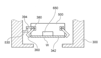
- the substrate holder 200 may be a substrate holder (cup type substrate holder) in which the substrate W is arranged sideways in the plating tank as shown in FIG.
- FIG. 16 is a schematic view showing a modified example of the substrate holder 200.
- the first member 300 has the contact member 530
- the second member 500 is the positioning member 360, the first moving member 380, the contacted member 394, and the Bernoulli chuck 650. And may have a support surface 342.
- the substrate W is attracted to the Bernoulli chuck 650, and the second member 500 holds the substrate W. Then, as the second member 500 descends, the first member 300 and the support surface 342 of the second member 500 sandwich the substrate W. Further, when the second member 500 is lowered, the contact member 530 of the first member 300 comes into contact with the contacted member 394, and the positioning member 360 moves to position the substrate W. Therefore, even if the substrate holder 200 is a cup-type substrate holder in this way, the substrate holder 200 can position the substrate W.
- FIG. 17 is a schematic view showing another modification of the substrate holder 200.
- the substrate W is placed on the support surface 342. Then, as the second member 500 descends, the first member 300 and the second member 500 sandwich the substrate W. Further, when the second member 500 is lowered, the contact member 530 of the first member 300 comes into contact with the contacted member 394, and the positioning member 360 moves to position the substrate W.
- the first member 300 has a positioning member 360, a first moving member 380, and a contacted member 394, and a second member 300 is provided.
- the member 500 may have a contact member 530, a Bernoulli chuck 650 and a support surface 342.
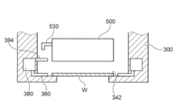
- FIG. 18 is a schematic view showing another modification of the substrate holder 200.
- the substrate W is attracted to the Bernoulli chuck 650, and the second member 500 holds the substrate W. Then, as the second member 500 descends, the first member 300 and the support surface 342 of the second member 500 sandwich the substrate W. Further, when the second member 500 is lowered, the contact member 530 of the second member 500 comes into contact with the contacted member 394, and the positioning member 360 moves to position the substrate W.
- the first member 300 has a positioning member 360, a first moving member 380, a contact member 394, and a support surface 342.
- the second member 500 may have a contact member 530.
- FIG. 19 is a schematic view showing another modification of the substrate holder 200.
- the substrate W is placed on the support surface 342. Then, as the second member 500 descends, the first member 300 and the second member 500 sandwich the substrate W. Further, when the second member 500 is lowered, the contact member 530 of the second member 500 comes into contact with the contacted member 394, and the positioning member 360 moves to position the substrate W.
- the substrate holder according to Appendix 1 has a support surface for supporting the substrate, and positions the substrate so that the central axis of the substrate is positioned on an ideal axis extending in a direction perpendicular to the support surface.
- Three or more substrate holders having a first holding member, a second holding member for sandwiching the substrate together with the first holding member, and a contact surface for contacting a side end portion of the substrate.
- a first moving member having a plurality of engaging portions to be engaged and a first urging member for urging the first moving member are provided, and the first moving member is an urging of the first urging member.
- the force is transmitted to each of the positioning members via the engaging portion, and the contact surface of each of the positioning members approaches the ideal axis due to the urging force transmitted from the first urging member. Being urged in the direction.
- each positioning member is urged in a direction in which the contact surface approaches the ideal axis. Therefore, when the substrate is placed on the support surface, the contact surface of the positioning member comes into contact with the side end portion of the substrate and pushes the substrate in the direction of the ideal axis. As a result, the three or more positioning members position the substrate so as to sandwich the substrate from the surroundings. At this time, the first moving member maintains a state in which the distance between the ideal axis and the contact surface of each positioning member is equal. Therefore, if the substrate is circular, the three or more positioning members can position the center of the sandwiched substrate on the ideal axis.
- this substrate holder can position the substrate even when the substrate receives frictional force or the like from the support surface.
- each positioning member is urged in a direction in which the contact surface approaches the ideal axis by the urging force transmitted from the first urging member. Therefore, the positioning member does not push the substrate with a force greater than the urging force transmitted from the first urging member. That is, no unnecessary load equal to or greater than the urging force of the first urging member is applied to the substrate, and this substrate holder can suppress damage to the substrate even when the substrate has dimensional tolerances.
- the positioning member has an engaged portion in which the engaging portion is movably engaged, and the first moving member is a first moving member. It is configured to be rotatable about the ideal axis, and when the first moving member rotates about the ideal axis, the rotation of the first moving member passes through the engaging portion and the engaged portion. It is transmitted to the positioning member, and the positioning member moves in the radial direction of the virtual circle centered on the ideal axis.
- the substrate holder according to Appendix 2 can transmit the urging force of the first urging member to the positioning member via the engaging portion and the engaged portion by rotating the first moving member around the ideal axis. it can. Further, the substrate holder can move the positioning member in the radial direction of the virtual circle centered on the ideal axis by the urging force of the first urging member.
- the engaged portion is a first pin or a first elongated hole, and the engaging portion engages with the first pin.
- the second slot or the second pin of the first moving member can be engaged with the first pin or the first slot of the positioning member.
- the rotation of the first moving member causes the second slot or the second pin of the first moving member to move and engage with the second slot or the second pin.
- the first pin or the first slot is pulled in the direction of the ideal axis.
- the positioning member having the second slot or the second pin moves in the radial direction of the virtual circle. That is, the substrate holder can move the positioning member in the radial direction of the virtual circle by using the first pin or the first slot and the second slot or the second pin.
- the substrate holder according to the appendix 5 includes a second moving member for rotating the first moving member about the ideal axis in the substrate holder according to any one of the appendices 2 to 4.
- the second moving member has a first pressing surface, is configured to be rotatable about the ideal axis, and is configured to be rotatable about the ideal axis.
- the member has a first pressed surface, and the first urging member is located between the first pressed surface of the first moving member and the first pressed surface of the second moving member. , The first moving member is urged through the first pressed surface.
- the first urging member can urge the first moving member via the first pressed surface.
- the second moving member has a second pressing surface and is configured to be rotatable about the ideal axis.
- the 1-moving member has a second pressed surface facing the second pressing surface, and the first urging member urges the first moving member so that the second pressed surface becomes the first. 2
- the first moving member is urged in a direction toward the pressing surface
- the second pressed surface comes into contact with the second pressing surface, and the second moving member rotates about the ideal axis.
- the second pressed surface rotates together with the second pressing surface, and the first moving member rotates in the same rotation direction as the second moving member.
- the first moving member rotates in the same rotation direction as the second moving member. Then, by rotating the first moving member, the positioning member is moved, and each positioning member sandwiches the side end portion of the substrate to perform positioning. Further, when the positioning member completes the positioning of the substrate, the positioning member cannot move due to the reaction force from the substrate, and the first moving member cannot rotate either. However, since the first urging member is located between the first pressed surface of the first moving member and the first pressing surface of the second moving member, the first urging member is compressed.
- the second moving member can rotate. That is, in this substrate holder, the second moving member can rotate while the positioning member and the first moving member are stopped.
- the substrate holder according to the appendix 8 is the substrate holder according to any one of the appendices 1 to 7, and is a second bias for rotating the first moving member in the first rotation direction about the ideal axis.
- a member is further provided, and when the first moving member rotates in the first rotation direction, the contact surface moves in a direction away from the ideal axis in conjunction with the rotation of the first moving member.
- the second urging member can rotate the first moving member in the first rotation direction. Further, the substrate holder can move the contact surface in a direction away from the ideal axis so as to be interlocked with the rotation of the first moving member.
- the second urging member is the second in the direction intersecting the radial direction of the virtual circle centered on the ideal axis. 2
- the moving member is urged to rotate the second moving member in the first rotation direction.
- the second urging member becomes the second by urging the second moving member in the direction in which the second urging member intersects the radial direction of the virtual circle centered on the ideal axis.
- the moving member can be rotated in the first rotation direction.
- the contact member is a protrusion fixed to the second holding member, and the contact member is orthogonal to the ideal axis.
- the protrusions abut on the inclined surface and the inclined surface is in contact with the inclined surface.
- the second moving member is configured to rotate in the second rotation direction, which is the rotation direction opposite to the first rotation direction, by the force received by the inclined surface from the protrusion. Will be done.
- the second holding member has a substrate sealing member for sealing between the second holding member and the substrate.
- the rotation of the second moving member by the contact member precedes the contact between the substrate sealing member and the substrate. It is done in.
- the substrate sealing member when the substrate sealing member comes into contact with the substrate in order to seal between the first holding member and the substrate, the substrate may move on the support surface due to the pressure from the substrate sealing member. In this case, even if the board is properly positioned, the board holder may not be able to hold the board in a properly positioned state.
- the rotation of the second moving member is performed before the contact between the substrate sealing member and the substrate. .. That is, after the second moving member rotates and the three or more positioning members are positioned so as to sandwich the substrate, the substrate seal member comes into contact with the substrate. Therefore, when the substrate receives the pressure from the substrate sealing member, three or more positioning members sandwich the substrate, so that the substrate does not easily move on the support surface. That is, this substrate holder can suppress the displacement of the substrate due to the pressure from the substrate sealing member.
- the first moving member is a pair extending in the circumferential direction of the virtual circle centered on the ideal axis. It is an arc-shaped member having side surfaces, and further includes a guide member for contacting each of the side surfaces and guiding the first moving member in the circumferential direction of a virtual circle centered on the ideal axis.
- the first moving member since the first moving member is guided by the guide member, the first moving member can rotate about the ideal axis.
- the distance between the ideal axis and the contact surface of the positioning member is longer than the radius of the substrate. It is configured to be movable from such a first position to a second position where the distance between the ideal axis and the contact surface is shorter than the radius of the substrate.
- the substrate holder according to the form 14 includes a first urging member.
- the positioning member has a first position in which the distance between the ideal axis and the contact surface is longer than the radius of the substrate, and a second position in which the distance between the ideal axis and the contact surface is shorter than the radius of the substrate. It is configured to be movable to. Therefore, even when the size of the substrate is smaller than the intended size, the three or more positioning members can position the substrate by sandwiching the substrate from the surroundings.
- the substrate processing apparatus performs a plating treatment on the substrate by using the substrate holder described in any one of the appendices 1 to 14.
- the substrate processing apparatus can perform plating processing using a substrate holder that can position the substrate and suppress damage to the substrate even when the substrate has dimensional tolerances.
- Plating device 200 Substrate holder 300: First member 310: First urging member 312: Second urging member 314: Guide member 320: First support base 330: Second support base 336: Guide member 340: Base 342: Support surface 360: Positioning member 370: Pin 376: Contact surface 380: First moving member 384: Slotted hole 386: First pressed surface 388: Second pressed surface 390: Second moving member 394: Contacted Member 398: First pressing surface 400: Second pressing surface 402: Inclined surface 500: Second member 518: Substrate sealing member 520: Holder sealing member 530: Contact member 902: First rotation direction 904: Second rotation direction L : Central axis, ideal axis W: Substrate
Landscapes
- Chemical & Material Sciences (AREA)
- Engineering & Computer Science (AREA)
- Chemical Kinetics & Catalysis (AREA)
- Materials Engineering (AREA)
- Metallurgy (AREA)
- Organic Chemistry (AREA)
- Electrochemistry (AREA)
- Life Sciences & Earth Sciences (AREA)
- Sustainable Development (AREA)
- General Chemical & Material Sciences (AREA)
- Mechanical Engineering (AREA)
- Container, Conveyance, Adherence, Positioning, Of Wafer (AREA)
Abstract
基板が支持面から摩擦力等を受ける場合にも、基板の位置決めができる、基板ホルダ及び基板処理装置を提供する。 本発明に係る基板ホルダ200は、第1保持部材300と、第1保持部材300と共に基板Wを挟持するための第2保持部材500と、基板Wの側端部と接触するための接触面342を有する3つ以上の位置決め部材360と、理想軸Lと、それぞれの位置決め部材360の接触面376との、それぞれの距離が等しい状態を維持して、位置決め部材360を移動させるように、それぞれの位置決め部材360と係合する複数の係合部384を有する第1移動部材380と、第1移動部材380を付勢する第1付勢部材310と、を備え、第1移動部材380は、第1付勢部材310の付勢力を、それぞれの位置決め部材360に伝達し、位置決め部材360は、伝達された付勢力により、接触面376が理想軸Lへ近づく向きへ付勢される。
Description
本発明は、基板ホルダ及び基板処理装置に関する。
基板の表面に金属薄膜を形成するために、めっき装置が使用されている。めっき装置では、半導体ウェハ等の基板を着脱自在に保持する基板ホルダが使用される場合がある。そして、めっき装置では、基板ホルダに保持された基板が、めっき液中に浸漬され、基板に電圧が印加されることで、基板の表面にめっきが施される。
基板ホルダの一例が特許文献1に記載されている。特許文献1には、その図3に示されるように、基板と接触するように構成される第1面を有する第1保持部材と、第1保持部材と共に基板を挟み込んで保持する第2保持部材と、を有する基板ホルダが開示されている。また、この基板ホルダの第1保持部材は、第1面に接触した基板を第1面の所定の位置に位置決めする位置決め部材を有している。そして、位置決め部材は、基板の周縁部と接触し、第1面の所定の位置に基板を位置決めする第1位置と、基板の周縁部より外側に位置し、基板と接触しない第2位置との間を移動するように構成されている。第2保持部材は、第1保持部材と第2保持部材とで基板を保持したときに、位置決め部材を第1位置に位置させるように構成された駆動部材を有している。
また、この基板ホルダでは、その図7に示されるように、位置決め部材は、先端部を有している。先端部は、第1先端部と第2先端部とに分岐し、第1先端部と第2先端部との間にスペースが生じている。第1先端部は、基板の径方向内側に位置し、第2先端部は、基板の径方向外側に位置している。そして、第1先端部は、基板と接触するように構成され、第2先端部は、駆動部材と接触するように構成されている。
特許文献1に記載の基板ホルダによれば、第1保持部材と第2保持部材とで基板を保持したときに、駆動部材が第2先端部と接触して、位置決め部材を第1位置に動かすことができる。このとき、第1位置に移動した位置決め部材の第1先端部が基板と接触することにより、この基板ホルダは、基板を位置決めすることができる。ここで、上述したように、第1先端部と第2先端部との間にスペースが存在している。このため、第1先端部が多少の弾性を有して基板に接触することができ、サイズが数mm異なる基板であっても、第1先端部がその数mmの寸法差を吸収して、位置決め部材により異なるサイズの基板を位置決めすることができる。
また、基板ホルダの別の一例が特許文献2に記載されている。特許文献2には、その図10に示されるように、可動保持部材と固定保持部材とを有する基板ホルダが開示されている。この基板ホルダは、可動保持部材と固定保持部材で基板を保持した時に、基板の外周端面と弾性的に接触して該基板の位置決めを行うばね性を有する複数の板ばね部材を可動保持部材に設けたことを特徴としている。
特許文献2に記載の基板ホルダによれば、基板を保持する過程で、基板をばね性を有する板ばね部材の弾性力で内方に付勢することで、この板ばね部材を介して、基板の基板ホルダに対する位置決め(センタリング)を行うことができる。
基板の位置決めの精度は、デバイスの進化と共にさらに高いレベルが要求されている。一方、前述したように、特許文献2では、弾性を有する板ばね部材(位置決め部材)を複数配置して基板の位置決めを行うことを記載している。しかしながら、実際には、基板と支持面との間の摩擦力等が存在する中で個々に弾性を有する板ばね部材が基板を互いに押し合うため、結果的に板ばね部材の変形量が同じになるとは限らず、すなわち基板の位置決めの精度が不十分なまま基板の保持が完了してしまう問題があった。
また、特許文献1に記載の基板ホルダは、第1先端部と第2先端部との間のスペースが特許文献2に記載の板ばね部材と同様の作用を奏していることから、特許文献2に記載の基板ホルダと基本的に同様の問題を有している。
そこで、本発明の目的は、上述した課題に鑑み、基板が支持面から摩擦力等を受ける場合にも、基板の位置決めができる、基板ホルダ及び基板処理装置を提供することである。
本発明に係る基板ホルダは、基板を支持するための支持面を有し、前記支持面と垂直方向に延びる理想軸上に前記基板の中心軸が位置するように前記基板の位置決めをするための、基板ホルダであって、第1保持部材と、前記第1保持部材と共に前記基板を挟持するための第2保持部材と、前記基板の側端部と接触するための接触面を有する3つ以上の位置決め部材と、前記理想軸と、それぞれの前記位置決め部材の前記接触面との、それぞれの距離が等しい状態を維持して、前記位置決め部材をそれぞれ同時に移動させるように、それぞれの前記位置決め部材と係合する複数の係合部を有する第1移動部材と、前記第1移動部材を付勢する第1付勢部材と、を備え、前記第1移動部材は、前記第1付勢部材の付勢力を、前記係合部を介して、それぞれの前記位置決め部材に伝達し、それぞれの前記位置決め部材は、前記第1付勢部材から伝達された付勢力により、前記接触面が前記理想軸へ近づく向きへ付勢される。
本発明に係る基板ホルダでは、それぞれの位置決め部材が、接触面が理想軸へ近づく向きへ付勢されている。このため、支持面に基板が置かれた場合、位置決め部材の接触面が基板の側端部と接触して、基板を理想軸の方向に押す。これにより、3つ以上の位置決め部材は、基板を周囲から挟み込むようにして、基板の位置決めをする。この時、第1移動部材は、理想軸と、それぞれの位置決め部材の接触面との、距離が等しい状態を維持している。このため、基板が円形であれば、3つ以上の位置決め部材は、挟み込む基板の中心を、理想軸上に位置させることができる。その結果、仮に基板が支持面から摩擦力等を受ける場合でも、位置決め後の基板の中心は、理想軸上に位置する。つまり、この基板ホルダは、基板が支持面から摩擦力等を受ける場合にも、基板の位置決めができる。
[第1実施形態]
以下、本実施形態について図面を参照しつつ説明する。まず、本実施形態に係る基板ホルダ200を備えるめっき装置100の全体構成について説明する。次いで、本実施形態に係る基板ホルダ200の構成について説明する。次いで、基板ホルダ200における位置決めされた基板Wの挟持方法を説明する。次いで、基板ホルダ200の効果について説明する。次いで、基板ホルダ200の変形例について説明する。なお、以下で説明する図面において、同一又は相当する構成要素には、同一の符号を付して重複した説明を省略する。
以下、本実施形態について図面を参照しつつ説明する。まず、本実施形態に係る基板ホルダ200を備えるめっき装置100の全体構成について説明する。次いで、本実施形態に係る基板ホルダ200の構成について説明する。次いで、基板ホルダ200における位置決めされた基板Wの挟持方法を説明する。次いで、基板ホルダ200の効果について説明する。次いで、基板ホルダ200の変形例について説明する。なお、以下で説明する図面において、同一又は相当する構成要素には、同一の符号を付して重複した説明を省略する。
<めっき装置の全体構成>
図1は、第1実施形態に係る基板ホルダ200を使用してめっき処理を行うめっき装置100の全体配置図である。図1を参照すると、めっき装置100は、2台のカセットテーブル102、アライナ104、スピンリンスドライヤ106、基板搬送装置108、基板着脱部120を備える。めっき装置100は、一例として、湿式で縦型の電解めっき装置であるが、横型でもよく、乾式の電解めっき装置又は無電解めっき装置でもよい。また、めっき装置100は、一例として、円形の基板Wに対しめっきを行う。
図1は、第1実施形態に係る基板ホルダ200を使用してめっき処理を行うめっき装置100の全体配置図である。図1を参照すると、めっき装置100は、2台のカセットテーブル102、アライナ104、スピンリンスドライヤ106、基板搬送装置108、基板着脱部120を備える。めっき装置100は、一例として、湿式で縦型の電解めっき装置であるが、横型でもよく、乾式の電解めっき装置又は無電解めっき装置でもよい。また、めっき装置100は、一例として、円形の基板Wに対しめっきを行う。
まず、めっき装置100の各構成要素について説明する。カセットテーブル102は、半導体ウェハ等の基板Wを収納したカセット103を搭載する機能を有する。スピンリンスドライヤ106は、めっき処理後の基板Wを高速回転させて乾燥させる機能を有する。基板着脱部120は、2つの載置プレート122を有する。基板着脱部120では、載置プレート122に載置された基板ホルダ200への基板Wの着脱が行われる。
基板搬送装置108は、カセットテーブル102、アライナ104、スピンリンスドライヤ106及び基板着脱部120の中央に配置されている。基板搬送装置108は、カセットテーブル102、アライナ104、スピンリンスドライヤ106及び基板着脱部120の間で基板Wを搬送する機能を有する。基板搬送装置108は、一例として、搬送用ロボットから構成される。
めっき装置100は、ストッカ124、プリウェット槽126、プリソーク槽128、第1洗浄槽130a、ブロー槽132、第2洗浄槽130b及びめっきユニット160をさらに備える。ストッカ124では、基板ホルダ200の保管及び一時仮置きが行われる。プリウェット槽126は、純水を保持する。プリウェット槽126は、基板Wを純水に浸漬して表面を濡らすことで、基板Wの親水性を良くする。プリソーク槽128は、硫酸を保持する。プリソーク槽128は、基板Wの表面に形成したシード層等の導電層の表面の酸化膜を、硫酸によりエッチング除去する機能を有する。第1洗浄槽130aは、洗浄液(純水等)を保持している。第1洗浄槽130aは、プリソーク後の基板Wを基板ホルダ200と共に洗浄液(純水等)で洗浄できる。ブロー槽132は、洗浄後の基板Wの液切りを行う機能を有する。第2洗浄槽130bは、めっき後の基板Wを基板ホルダ200と共に洗浄液で洗浄する機能を有する。
めっきユニット160は、一例として、隣接した複数のめっき槽162と、複数のめっき槽162の外周を取り囲むオーバーフロー槽164とを含む。各めっき槽162は、一例として、内部に1つの基板Wを収納し、内部に保持しためっき液中に基板Wを浸漬させて、基板Wの表面に銅めっき等のめっきを施すように構成されている。なお、プリウェット槽126、プリソーク槽128、第1洗浄槽130a、ブロー槽132、第2洗浄槽130b及びめっき槽162は、処理槽180と呼ぶことができる。すなわち、処理槽180は、基板Wを処理するための槽である。
めっき装置100は、基板ホルダ搬送装置190をさらに備える。そして、基板ホルダ搬送装置190は、水平レール192、第1トランスポータ194a及び第2トランスポータ194bを備える。なお、第1トランスポータ194a及び第2トランスポータ194bは、同じ構造を有しており、それぞれ単にトランスポータ194と呼ぶことができる。基板ホルダ搬送装置190は、直線状に並んだ基板着脱部120、ストッカ124、プリウェット槽126、プリソーク槽128、第1洗浄槽130a、ブロー槽132、第2洗浄槽130b、及びめっきユニット160の側方に位置する。基板ホルダ搬送装置190には、一例として、リニアモータ方式が採用されている。水平レール192は、直線状に並ぶ各処理槽180に隣接して、直線状に延びる。
第1トランスポータ194aは、一例として、基板着脱部120、ストッカ124、プリウェット槽126、プリソーク槽128、第1洗浄槽130a、及びブロー槽132との間で基板ホルダ200を搬送するように構成されている。第2トランスポータ194bは、一例として、第1洗浄槽130a、第2洗浄槽130b、ブロー槽132、及びめっき槽162の間で基板ホルダ200を搬送するように構成されている。
<基板ホルダの構成>
次に、図1に示した、めっき装置100おいて使用される基板ホルダ200について詳細に説明する。図2は、基板ホルダ200の斜視図である。図2を参照すると、基板ホルダ200は、第1部材300(第1保持部材の一例)、第2部材500(第2保持部材の一例)、ヒンジ220及び一対のハンド240を備える。第2部材500は、環状形状を有するシールホルダ540及び、シールホルダ540からヒンジ220まで延びヒンジ220によって支持されている平板状の基部502を有している。また、ヒンジ220は、第2部材500と第1部材300とを接続している。このため、第2部材500は、ヒンジ220を支点として回転自在に構成されている。そして、第2部材500が回転して閉じられることにより、基板ホルダ200は、第1部材300と第2部材500とで基板Wを挟持することができる。つまり、基板ホルダ200は、基板Wを保持する機能を有する。第2部材500には、開口504が形成されている。開口504は、基板Wの大きさよりもやや小さい。基板Wが第1部材300と第2部材500との間に挟まれているとき、基板Wの被処理面は、開口504を通して露出される。つまり、基板ホルダ200が処理槽180に保持されたときに、処理槽180の処理液は、基板Wの露出した被処理面に接触することができる。これにより、基板Wの被処理面に処理が施される。
次に、図1に示した、めっき装置100おいて使用される基板ホルダ200について詳細に説明する。図2は、基板ホルダ200の斜視図である。図2を参照すると、基板ホルダ200は、第1部材300(第1保持部材の一例)、第2部材500(第2保持部材の一例)、ヒンジ220及び一対のハンド240を備える。第2部材500は、環状形状を有するシールホルダ540及び、シールホルダ540からヒンジ220まで延びヒンジ220によって支持されている平板状の基部502を有している。また、ヒンジ220は、第2部材500と第1部材300とを接続している。このため、第2部材500は、ヒンジ220を支点として回転自在に構成されている。そして、第2部材500が回転して閉じられることにより、基板ホルダ200は、第1部材300と第2部材500とで基板Wを挟持することができる。つまり、基板ホルダ200は、基板Wを保持する機能を有する。第2部材500には、開口504が形成されている。開口504は、基板Wの大きさよりもやや小さい。基板Wが第1部材300と第2部材500との間に挟まれているとき、基板Wの被処理面は、開口504を通して露出される。つまり、基板ホルダ200が処理槽180に保持されたときに、処理槽180の処理液は、基板Wの露出した被処理面に接触することができる。これにより、基板Wの被処理面に処理が施される。
一対のハンド240は、第1部材300の端部に固定されている。それぞれのハンド240は、一例として、T字形状をしていて、基板ホルダ200を搬送したり吊下げ支持したりする際の支持部となる。ハンド240が図1に示した各処理槽180の周壁上面に引っ掛けられることにより、基板ホルダ200は垂直に吊下げられた状態で支持される。また、トランスポータ194は、ハンド240を把持でき、ハンド240を把持した状態で基板ホルダ200を搬送する。また、一方のハンド240には、外部電源と電気的に接続される外部接点部242が設けられている。外部接点部242は、複数の導線を介してベース340の外周に設けられた複数の導電部材306(図3及び図4参照)と電気的に接続されている。
図3は、基板ホルダ200を正面方向から見た概略図であり、図4は基板Wを保持した状態の基板ホルダ200の厚さ方向の切断面における部分拡大図である。図4を参照すると、第1部材300は、複数のクランパ302、締結具304、第1支持ベース320、第2支持ベース330、ベース340及び導電部材306、をさらに有している。また、第2部材500は、押えリング506、スペーサ512、第1固定リング514、第2固定リング516、基板シール部材518、ホルダシール部材520、締結具522、締結具524、接触部材526及び締結具528をさらに有している。
第1支持ベース320は、一例として、略矩形平板状の形状をしていて、塩化ビニルから構成されている(図3参照)。第1支持ベース320には、第2支持ベース330、複数のクランパ302が固定されている。第2支持ベース330は、略円盤形状である。第2支持ベース330には、ベース340が固定されている。ベース340は、基板Wを支持する機能を有する。ベース340は、中心軸Lを中心とするリング形状を有し、基板Wの外周部に当接して基板Wを支持するための支持面342を備える。なお、中心軸Lと支持面342とは直交している(図2参照)。別言すると、中心軸Lは、支持面342に対し垂直方向に延びる。
シールホルダ540は、一例として、塩化ビニルで構成されている。また、シールホルダ540には、環状の第1固定リング514が締結具522により取付けられている。そして、環状の基板シール部材518は、シールホルダ540と第1固定リング514とに挟持されている。また、シールホルダ540には、環状の第2固定リング516が締結具524により取付けられている。そして、環状のホルダシール部材520は、シールホルダ540と第2固定リング516とに挟持されている。つまり、シールホルダ540には、基板シール部材518及びホルダシール部材520が取付けられている。なお、基板ホルダ200では、一例として、シールホルダ540、基板シール部材518及びホルダシール部材520の中心は、一例として、中心軸L上に位置している。
基板シール部材518は、基板ホルダ200で基板Wを保持したときに、基板Wの表面の外周部付近に接触する。これにより、基板シール部材518は、基板Wと第2部材500との間の隙間をシールする機能を有する。他方、ホルダシール部材520は、基板ホルダ200が基板Wを保持したときに、第1部材300に接触する。これにより、ホルダシール部材520は、第1部材300と第2部材500との間の隙間をシールする機能を有する。このため、基板ホルダ200で基板Wを保持すると、図4に示すように、基板シール部材518及びホルダシール部材520でそれぞれシールされた内部空間R1が基板ホルダ200の内部に形成される。
複数のクランパ302は、後述する突起508と係合し、突起508と共に、第2部材500を第1部材300に固定する機能を有する。クランパ302は、逆L字状であり、支持面342の方向に突出する突出部303を有している。また、クランパ302は、支持面342の周囲に沿って、略等間隔に配置され(図3参照)、それぞれのクランパ302は、第1支持ベース320に締結具304により固定されている。
また、シールホルダ540には、外周部に段部542が形成されている。段部542には、押えリング506がスペーサ512を介して回転自在に装着されている。押えリング506は、一例として、酸に対して耐食性に優れ、且つ十分な剛性を有する金属(例えばチタン)から構成されている。スペーサ512は、押えリング506がスムーズに回転できるように、摩擦係数の低い材料で構成されている。なお、基板ホルダ200では、スペーサ512は、一例として、PTFE(ポリテトラフルオロエチレン)から構成されている。
また、押えリング506は、突起508を有する。突起508は、複数のクランパ302と対向する位置に、押えリング506の外方に突出するように設けられていている(図3参照)。また、突起508の上面は、押えリング506の回転方向に沿って傾斜するテーパ面であり、突起508の上面と接触するクランパ302の突出部303の下面も、傾斜するテーパ面である。そして、押えリング506が時計回りに回転することで、突起508が、クランパ302の突出部303に滑り込むように、突起508及びクランパ302は構成されている。つまり、押えリング506が時計回りに回転することで、第2部材500は、第1部材300に固定される。他方、押えリング506が反時計回りに回転することで、第2部材500の第1部材300に対する固定が解除される。
また、図3に示すように、ベース340の円周方向に沿った所定位置には、凹部344が形成されている。各凹部344内には複数(図示では12個)の導電部材306が配置されている。そして、図4に示すように、第2部材500が閉じられているときには、導電部材306の端部は、接触部材526に接触するように構成される。他方、第2部材500が開いているときには、接触部材526は導電部材306から離間するように構成されている。
また、接触部材526は、一例として、内部空間R1に位置し、導電性の板ばねから構成される。接触部材526は、締結具528によりシールホルダ540に固着されている。そして、第1部材300と第2部材500とで基板Wを挟持したときには、接触部材526は、基板Wの被処理面側の縁近傍に弾性的に接触するように構成されている。つまり、基板ホルダ200が基板Wを挟持しているときには、ハンド240の外部接点部242と、基板Wとは導通する。なお、接触部材526は導電部材306と同じ数だけ(基板ホルダ200では12個)設けられている。
図5は、基板ホルダ200の第1部材300の部分の正面図である。図5を参照すると、第1部材300は、支持面342を囲むように配置された6つの位置決め部材360をさらに有する。基板ホルダ200は、後述する方法により、位置決め部材360を用いて、基板ホルダ200に対する基板Wの位置決めをする機能を有する。なお、本明細書では、位置決めとは、基板Wの中心が理想軸上に位置する位置に、基板Wを移動させることを意味する。また、理想軸とは、基板ホルダ200において、基板Wの中心が位置すべき点を通り支持面342に垂直な直線である。さらに、本実施形態では、理想軸は、中心軸Lと一致している。このため、理想軸が、図中の直線Lを示す場合には、理想軸Lと記載される。
図6は、図5のA-A断面図であり、位置決め部材360が第1位置に位置しているときの図である。図7は、図5のA-A断面図であり、位置決め部材360が第2位置に位置しているときの図である。また、図8は、位置決め部材360の断面斜視図である。なお、図8では、図面を見易くするために、シート308が省略されている。
図8を参照すると、位置決め部材360は、一例として、略L字型の部材であり、支持部材362、L字部材364及び2つの締結具366を有する。支持部材362は、直方体のブロック状の部材であり、長手方向に直線状に延びる溝368が形成されている。また、支持部材362は、溝368が形成された面の反対側の面に、理想軸Lと平行に延びるピン370(被係合部370の一例)を有している。L字部材364は、略L字型の部材であり、被固定部372と、被固定部372と略直交して支持面342の上まで延びる先端部374と、を有する。被固定部372が支持部材362の溝368に嵌り込んだ状態で、L字部材364は、2つの締結具366により支持部材362に固定されている。また、先端部374は、基板Wの位置決めのときに、基板Wと接触する。この基板Wと接触する面のことを接触面376と呼ぶ。別言すると、位置決め部材360は、基板Wの側端部と接触するための接触面376を有している。
また、第2支持ベース330には、理想軸Lを中心とする仮想円VC(図5参照)の半径方向へ延びる直線状の溝332が形成されている。位置決め部材360は、溝332にはめ込まれている。これにより、位置決め部材360は、溝332に沿って移動することができる。より具体的には、位置決め部材360は、図6に示される理想軸Lから離れた第1位置から、図7に示される第1位置よりも位置決め部材360が理想軸Lに近づいた第2位置まで移動可能である。なお、位置決め部材360が第1位置にあるときの、理想軸Lと接触面376との距離は、基板Wの半径よりも長く、位置決め部材360が第2の位置にあるときの、理想軸Lと接触面376との距離は、基板Wの半径よりも短い。
また、第1部材300は、後述する第1移動部材380と第1支持ベース320との間に位置するシート308をさらに有している(図6参照)。シート308は、一例として、テフロン(登録商標)から構成されている。これにより、第1移動部材380が回転するときの、第1移動部材380と第1支持ベース320との間の摩擦は低減される。
図9は、基板ホルダ200を背面方向から見た部分断面図である。図9の断面線900の内部では、第1支持ベース320が省略されている。図10は、図9のB部の拡大図である。図9の矢印902の示す方向を第1回転方向902とし、第1回転方向902と反対の回転方向を第2回転方向904とする。
図9を参照すると、第1部材300は、第1移動部材380をさらに有している。第1移動部材380は、一例として、円弧状の部材である。そして、第1移動部材380は、理想軸Lを中心とする仮想円VCの円周方向に延びる一対の側面382を有している。また、第2支持ベース330には、理想軸Lを中心とする円弧状の溝334が形成されている。そして、第2支持ベース330は、複数の案内部材336を有している。案内部材336は、第1移動部材380のそれぞれの側面382と接触し、第1移動部材380を、理想軸Lを中心とする仮想円VCの円周方向に案内する機能を有している。このため、第1移動部材380は、溝334にはめ込まれた状態で複数の案内部材336により案内されている。つまり、第1移動部材380は、理想軸Lを中心として回転可能に構成されている。
また、図9に示されるように、第1移動部材380には、それぞれの位置決め部材360に対応する複数の長穴384(係合部384の一例)が形成されている。そして、長穴384の長手方向は、理想軸Lを中心とする仮想円VCの半径方向及び円周方向と交わる方向である。長穴384は、位置決め部材360のピン370と係合している(図10参照)。これにより、第1移動部材380が回転すると、位置決め部材360が、第1移動部材380と連動して移動する。具体的には、位置決め部材360が図6に示す第1位置にあるときに、第1移動部材380が、第2回転方向904に回転すると、長穴384が移動し、長穴384に係合しているピン370が長穴384の側周面により理想軸Lの方向へ引っ張られる。そして、この長穴384の側周面からの引張りによる力で、位置決め部材360は、理想軸Lの方向に移動し、図7に示す第2位置に到達する。他方、第1移動部材380が、図7に示す第2位置にあるときに、第1移動部材380が第1回転方向902に回転する場合、位置決め部材360は、理想軸Lから離れる方向に引っ張られ、図6に示す第1位置に移動する。なお、基板ホルダ200では、位置決め部材360と第1移動部材380とは、上述のように接続されるため、位置決め部材360と第1移動部材380との間に、位置決め部材360を付勢するための板ばねや弾性ばね等の付勢部材は存在しない。
また、第1移動部材380が回転するときに、複数の長穴384が一斉に移動する。これにより、第1移動部材380は、複数の位置決め部材360をそれぞれ同時に動作させることができる。別言すると、第1移動部材380が回転すると、第1移動部材380の回転が長穴384及びピン370を介して位置決め部材360に伝達され、位置決め部材360が理想軸Lを中心とする仮想円VCの半径方向に移動する。また、位置決め部材360の移動時に、理想軸Lと、それぞれの位置決め部材360の接触面376との、それぞれの距離が等しい状態を維持するように、位置決め部材360及び第1移動部材380は構成されている。
図11は、図9のC部の拡大図であり、第2移動部材390が定常位置に位置しているときの図であり、図11では、第2被押圧面388が第2押圧面400と当接している。また、図12は、図9のC部の拡大図であり、第2移動部材390が変位位置に位置して、第2被押圧面388が第2押圧面400と当接しているときの図である。図13は、図9のC部の拡大図であり、第2移動部材390が変位位置に位置して、第2被押圧面388が第2押圧面400から離間しているときの図である。
図11を参照すると、第1部材300は、第2移動部材390及び案内部材314を有する。第2移動部材390は、図11におけるハッチングで示されている部品である。第2移動部材390は、第2支持ベース330の溝334にはまり込んでいる。また、第2移動部材390は、円弧状の回転部材392及び回転部材392から理想軸Lを中心とする仮想円VCの半径方向に延びる被当接部材394を有している。回転部材392は、理想軸Lを中心とする仮想円VCの円周方向に延びる一対の側面396を有している。また、案内部材314は、第2支持ベース330の溝334の内部に位置する。そして、案内部材314は、回転部材392のそれぞれの側面396と接触し、回転部材392を、理想軸Lを中心とする仮想円VCの円周方向に案内する機能を有する。これにより、第2移動部材390は、理想軸Lを中心として回転可能に構成されている。また、第2移動部材390は、第2支持ベース330と当接することで、回転が規制される。このため、第2移動部材390は、図11に示される定常位置から、図12及び図13に示される変位位置まで回転可能である。なお、変位位置は、一例として、第2移動部材390が定常位置から第2回転方向904に移動して停止したときのある位置である。
また、第1部材300は、複数の第1付勢部材310を有する。第1付勢部材310は弾性を有する部材であり、一例として、バネである。そして、第2移動部材390は、一例として、複数の第1押圧面398を有している。第1移動部材380は、一例として、第1押圧面398と対向する第1被押圧面386を有している。第1付勢部材310は、第1被押圧面386と第1押圧面398との間に位置し、第1被押圧面386を介して第1移動部材380を第2回転方向904に付勢している。すなわち、第1付勢部材310は、圧縮状態にある。第1移動部材380が第1付勢部材310からの付勢力により第2回転方向904に回転したときに、第1付勢部材310の付勢力が長穴384及びピン370を介して位置決め部材360に伝達される。その結果、第1付勢部材310から伝達された付勢力により、接触面376が理想軸Lへ近づく向きへ付勢される(図9参照)。そして、位置決め部材360が理想軸Lを中心とする仮想円VCの半径方向に移動する。つまり、第1移動部材380は、第1付勢部材310の付勢力をそれぞれの位置決め部材360に伝達する機能を有している。
また、第2移動部材390は、一例として、第2押圧面400を有していて、第1移動部材380は、一例として、第2押圧面400と対向する第2被押圧面388を有している。そして、第1付勢部材310が第1移動部材380を付勢することで、第1移動部材380は、第2被押圧面388が第2押圧面400に向かう向きに付勢され、第2被押圧面388が第2押圧面400と当接している(図9参照)。
ここで、第2移動部材390が図11に示される定常位置から第2回転方向904に回転する場合の各構成要素の挙動について説明する。ベース340上に基板Wがないときに、第2移動部材390が外力を受けて、定常位置から第2回転方向904に回転した場合、図12に示されるように、第2被押圧面388が第2押圧面400と共に離間することなく回転する。別言すると、第2移動部材390が理想軸Lを中心として回転したときに、第1移動部材380が第2移動部材390と同一の回転方向に回転する。このとき、上述した位置決め部材360は、第1移動部材380の回転と連動して、理想軸Lに近づく向きに移動する。
他方、ベース340上に基板Wが載置されているときに、第2移動部材390が外力を受けて、定常位置から第2回転方向904に回転した場合、当初は、ベース340上に基板Wがないときと同様に、第2被押圧面388が第2押圧面400と共に回転する。このとき、位置決め部材360は、第1移動部材380の回転と連動して、理想軸Lに近づく向きに移動する。しかしながら、各位置決め部材360が、基板Wの側端部を挟持して、位置決め部材360が基板Wの位置決めを完了すると、位置決め部材360は、基板Wからの反力により、移動することができなくなる。そして、第1移動部材380は回転できなくなる。さらに、第2移動部材390が第2回転方向904に回転すると、第1移動部材380が回転することなく、第1付勢部材310が圧縮される。このため、図13に示されるように、第2押圧面400が第2被押圧面388から離間する。つまり、基板ホルダ200では、第1付勢部材310がクッションの役割を果たすことで、位置決め部材360が停止した状態で、第2移動部材390が回転することができる。このように、位置決め部材360が基板Wの位置決めを完了した後も、第2移動部材390が第2回転方向904に回転することを可能としている。これは、第2部材500が閉じ切る前に、確実に基板Wの位置決めを完了させるとともに、基板Wの大きさバラツキがあっても基板Wの位置決めが確実に行われるようにするためである。
上述したように、図12は、基板Wがない場合の各構成要素の挙動を説明するために用いられたが、基板Wが存在しており、第2部材500が閉じる途中で位置決め部材360による基板Wの位置決めが完了した状態も、図12に示される状態とほぼ同じである。すなわち、理想的な挙動として説明すれば、基板Wの位置決めが完了した時点では、図12に示される状態のように、第2被押圧面388と第2押圧面400は接触している。なお、このとき、位置決め部材360の位置に応じて、第1移動部材380及び第2移動部材390は、図12に示される状態と異なり、第1回転方向902に回転した位置に位置する場合があり得る。これは、上述の記述から、当業者であれば理解できるであろう。
次に、第2移動部材390が図12に示される変位位置から第1回転方向902に回転する場合の各構成要素の挙動について説明する。第2移動部材390が図12に示される位置にあるときに、第1回転方向902に回転した場合、第2移動部材390が定常位置に戻るまでの間、第2押圧面400が第2被押圧面388を押圧する。そして、第1付勢部材310が、第1回転方向902に回転し、位置決め部材360は、理想軸Lから離れる向きに移動する。図11に示されるように、第2移動部材390が定常位置に位置したときに、位置決め部材360は、図6に示す第1位置に移動する。
次に、第2移動部材390が図13に示される変位位置から第1回転方向902に回転する場合の各構成要素の挙動について説明する。第2移動部材390が図13に示される位置にあるときに、第2押圧面400と第2被押圧面388とは、当接していない。このため、第2移動部材390が第1回転方向902に回転した場合、第2押圧面400が第2被押圧面388と当接するまでは、第1移動部材380及び位置決め部材360は移動しない。しかし、第2押圧面400が第2被押圧面388と当接すると、第1移動部材380及び位置決め部材360の移動が開始する。これにより、位置決め部材360は、理想軸Lから離れる向きに移動する。言い換えると、図13に示される変位位置から、第2移動部材390が第1回転方向902に回転する場合、まず第2被押圧面388と第2押圧面400とが当接するまで、第1移動部材380は回転せず、第2移動部材390が回転する。第2被押圧面388と第2押圧面400とが当接した後は、当接したまま、第1移動部材380と第2移動部材390がともに第1回転方向902に回転する。そして、図11に示されるように、第2移動部材390が定常位置に位置したときには、第2移動部材390が図12に示される変位位置から第1回転方向902に回転する場合と同様に、位置決め部材360は、図6に示す第1位置に移動する。
このように、第2移動部材390が理想軸Lを中心として回転したときに、第2移動部材390は、第1移動部材380を、理想軸Lを中心として回転させることができる。すなわち、第2移動部材390は、第1移動部材380を、理想軸Lを中心として回転させる機能を有している。
また、図11を参照すると、第1部材300は、一例として、複数の第2付勢部材312を有する。第2付勢部材312は弾性を有する部材であり、一例として、バネである。第2付勢部材312は、一例として、第2支持ベース330と、第2移動部材390との間に位置し、仮想円VCの接線方向に第2移動部材390を付勢している。つまり、第2付勢部材312は、第2移動部材390を第1回転方向902に回転させる機能を有する。また、前述したように、第2移動部材390は、第1移動部材380を、理想軸Lを中心として回転させる機能を有している。このため、第2移動部材390が第1回転方向902に回転すれば、第1移動部材380も、同一回転方向である第1回転方向902に回転する。つまり、第2付勢部材312が第2移動部材390を付勢すれば、第1移動部材380が、第2移動部材390とともに、第1回転方向902に回転する。すなわち、第2付勢部材312は、第2移動部材390だけでなく、第1移動部材380を回転させる機能も有する。
図14(a)は、図3のD-D断面の概略図であり、(b)は、(a)のE-E断面図である。図15(a)は、第2部材500が閉じる途中の状態の、図3のD-D断面の概略図であり、(b)は、(a)のF-F断面図である。図14(a)を参照すると、第2部材500は、当接部材530を有する。当接部材530は、一例として、第2部材500に固定された円柱状の突起530である。突起530は、円柱の側周面が傾斜面402と当接できるように構成されている。また、第1部材300の被当接部材394は、理想軸Lに直交する平面に対して傾斜する傾斜面402を有している(図14(b)参照)。傾斜面402の法線の方向は、理想軸L方向の成分と、仮想円VCの接線方向の成分を有している。
第1部材300と第2部材500とが基板Wを挟持するときに、第2部材500は、図15に示された位置から図14に示された位置まで移動する。このとき、突起530は、傾斜面402と当接し、傾斜面402を理想軸Lの延びる方向に押圧できる。そして、第2移動部材390は、傾斜面402が突起530から受けた力により第2回転方向904に回転する。別言すれば、第2移動部材390は、定常位置から変位位置へ回転する。
他方、第2部材500が開かれる場合、傾斜面402を押圧していた突起530が傾斜面402から離れる方向であって、略理想軸Lの延びる方向へ移動する。これにより、第2移動部材390が第2付勢部材312から受ける付勢力により、傾斜面402は、突起530が傾斜面402と当接する前の位置に戻る。すなわち、第2部材500が開かれることで、第2移動部材390は、次第に第1回転方向902に移動し、変位位置から定常位置へ戻る(図11参照)。
また、第1部材300と第2部材500とが基板Wを挟持するときの、突起530による、第2移動部材390の回転、さらに位置決め部材360の理想軸Lの方向への移動が、基板シール部材518と基板Wとの接触(図4参照)よりも先に行われるように、基板ホルダ200は構成されている。
<基板ホルダにおける位置決めされた基板の挟持方法>
次に、支持面342に基板Wが置かれていない状態(初期状態)からの、基板ホルダ200における位置決めされた基板Wの挟持方法を説明する。
次に、支持面342に基板Wが置かれていない状態(初期状態)からの、基板ホルダ200における位置決めされた基板Wの挟持方法を説明する。
まず、図2に示されるように、第2部材500が開かれた状態において、基板Wが支持面342上に置かれる。次いで、第2部材500が閉じられる。このとき、第2部材500の突起530が、第1部材300の傾斜面402と当接し、第2移動部材390を回転させる(図14及び図15参照)。第2移動部材390が回転を開始すると、上述したように、第1移動部材380が第2移動部材390と共に回転する(図9参照)。そして、第1移動部材380が回転することで、位置決め部材360が、理想軸Lの方向へ移動する。これにより、位置決め部材360の接触面376が、支持面342に置かれた基板Wの側端部と接触して、基板Wを理想軸Lの方向に押し、6つの位置決め部材360は、基板Wを周囲から挟み込むようにして、基板Wの位置決めをする。しかし、基板Wの位置決めが完了したときに、第2部材500は、まだ完全に閉じ切っていない。そのため、さらに第2部材500が閉じられる。これにより、第2移動部材390は、第1の方向へさらに回転し、図13に示される変位位置まで移動する。なお、このとき、位置決め部材360は、基板Wをこれ以上移動させることができず、第1移動部材380は回転できない。このため、第1付勢部材310が圧縮される。
また、第2部材500が完全に閉じ切る直前に、基板シール部材518は、基板Wの表面に接触し、基板Wと第2部材500との間の隙間をシールする。その後、第2部材500が完全に閉じ切ると、押えリング506が回され、第2部材500は、クランパ302により、第1部材300に固定される。以上で、基板ホルダ200において、位置決めされた基板Wの挟持が完了する。
<基板ホルダの効果>
次に、第1実施形態に係る基板ホルダ200の効果について、以下に説明する。
次に、第1実施形態に係る基板ホルダ200の効果について、以下に説明する。
(第1の効果)
第1の効果は、基板ホルダ200が、ベース340、6つの位置決め部材360、第1移動部材380及び第1付勢部材310を備えることによる効果である。上述したように、6つの位置決め部材360が、接触面376が理想軸Lへ近づく向きへ付勢されている。このため、支持面342に基板Wが置かれた場合、位置決め部材360が、第1位置から、第2位置に向かう方向へ移動する。そして、6つの位置決め部材360は、ベース340の支持面342に置かれた基板Wを周囲から挟み込むようにして、基板Wの位置決めをする。このとき、第1移動部材380は、理想軸Lと、それぞれの位置決め部材360の接触面376との、距離が等しい状態を維持している。このため、6つの位置決め部材360は、位置決めのときに、基板Wの中心を、理想軸L上に位置させることができる。その結果、仮に基板Wが支持面342から摩擦力等を受ける場合でも、位置決め後の基板Wの中心は、理想軸L上に位置する。つまり、基板ホルダ200は、基板Wが支持面342から摩擦力等を受ける場合にも、基板Wの位置決めができる。
第1の効果は、基板ホルダ200が、ベース340、6つの位置決め部材360、第1移動部材380及び第1付勢部材310を備えることによる効果である。上述したように、6つの位置決め部材360が、接触面376が理想軸Lへ近づく向きへ付勢されている。このため、支持面342に基板Wが置かれた場合、位置決め部材360が、第1位置から、第2位置に向かう方向へ移動する。そして、6つの位置決め部材360は、ベース340の支持面342に置かれた基板Wを周囲から挟み込むようにして、基板Wの位置決めをする。このとき、第1移動部材380は、理想軸Lと、それぞれの位置決め部材360の接触面376との、距離が等しい状態を維持している。このため、6つの位置決め部材360は、位置決めのときに、基板Wの中心を、理想軸L上に位置させることができる。その結果、仮に基板Wが支持面342から摩擦力等を受ける場合でも、位置決め後の基板Wの中心は、理想軸L上に位置する。つまり、基板ホルダ200は、基板Wが支持面342から摩擦力等を受ける場合にも、基板Wの位置決めができる。
(第2の効果)
また、仮に基板ホルダ200が第1付勢部材310を備えない場合に、第2移動部材390が変位位置まで移動すると、位置決め部材360は決まった位置まで閉じてしまう。このため、意図した大きさの基板Wの位置決めしかすることができない。例えば、仮に、第1付勢部材310を備えない基板ホルダ200が、意図した大きさよりも大きな基板Wを位置決めする場合、位置決め部材360が基板Wの側端部と接触した後も、位置決め部材360は、決まった位置まで移動することになる。この場合、位置決め部材360は、基板Wに不必要な負荷をかけるおそれがある。そして、この負荷により、基板Wが破損するおそれがある。
また、仮に基板ホルダ200が第1付勢部材310を備えない場合に、第2移動部材390が変位位置まで移動すると、位置決め部材360は決まった位置まで閉じてしまう。このため、意図した大きさの基板Wの位置決めしかすることができない。例えば、仮に、第1付勢部材310を備えない基板ホルダ200が、意図した大きさよりも大きな基板Wを位置決めする場合、位置決め部材360が基板Wの側端部と接触した後も、位置決め部材360は、決まった位置まで移動することになる。この場合、位置決め部材360は、基板Wに不必要な負荷をかけるおそれがある。そして、この負荷により、基板Wが破損するおそれがある。
しかし、基板ホルダ200は、第1付勢部材310を備える。そして、それぞれの位置決め部材360は、第1付勢部材310から伝達された付勢力により、接触面376が理想軸Lへ近づく向きへ付勢されている。このため、位置決め部材360は、第1付勢部材310から伝達された付勢力以上の力で、基板Wを押さない。つまり、基板Wは、第1付勢部材310の付勢力以上の不必要な負荷がかからず、基板ホルダ200は、基板Wが寸法公差を有する場合でも基板Wの破損を抑止できる。
(第3の効果)
また、仮に、第1付勢部材310を備えない基板ホルダ200が、意図した大きさよりも小さな基板Wを位置決めする場合、位置決め部材360が決まった位置に位置したときに、基板Wと、位置決め部材360との間に空間が生じる。そして、この空間の分だけ基板Wは、自由に動くことができ、基板Wが正確に位置決めされないおそれがある。
また、仮に、第1付勢部材310を備えない基板ホルダ200が、意図した大きさよりも小さな基板Wを位置決めする場合、位置決め部材360が決まった位置に位置したときに、基板Wと、位置決め部材360との間に空間が生じる。そして、この空間の分だけ基板Wは、自由に動くことができ、基板Wが正確に位置決めされないおそれがある。
しかし、基板ホルダ200は、第1付勢部材310を備える。そして、ベース340上に基板Wが載置されてないときに、位置決め部材360が、理想軸Lと接触面376との距離が基板Wの半径よりも長くなるような第1位置から、理想軸Lと接触面376との距離が基板Wの半径よりも短くなるような第2位置まで移動可能に構成されている。このため、基板Wの大きさが寸法公差の範囲内で変化して、基板Wが意図した大きさよりも小さい場合であっても、6つの位置決め部材360は、基板Wを周囲から挟み込むようにして、基板Wの位置決めをすることができる。
(第4の効果)
また、基板ホルダ200では、上述したように、第2部材500が閉じることで、第1移動部材380及び第2移動部材390が第2回転方向904に回転し、位置決め部材360が、理想軸Lへ近づく向きへ移動し、基板Wの位置決めを行う。つまり、第2部材500が閉じるだけで、基板ホルダ200は、基板Wを位置決めできる。
また、基板ホルダ200では、上述したように、第2部材500が閉じることで、第1移動部材380及び第2移動部材390が第2回転方向904に回転し、位置決め部材360が、理想軸Lへ近づく向きへ移動し、基板Wの位置決めを行う。つまり、第2部材500が閉じるだけで、基板ホルダ200は、基板Wを位置決めできる。
(第5の効果)
第5の効果は、基板ホルダ200が、位置決め部材360、第1移動部材380、第2移動部材390及び第1付勢部材310を備えることによる効果である。上述したように、第2移動部材390が第2回転方向904に回転した場合、第1移動部材380が回転する(図11参照)。そして、第1移動部材380が回転することにより、位置決め部材360を移動させ、各位置決め部材360が、基板Wの側端部を挟持して、位置決めを行う。また、位置決め部材360が基板Wの位置決めを完了すると、基板Wからの反力により、位置決め部材360は移動することができず、第1移動部材380も回転することができない。しかし、第1移動部材380の第1被押圧面386と第2移動部材390の第1押圧面398との間に第1付勢部材310が位置しているため、第1付勢部材310が圧縮されることにより、第2移動部材390は回転できる。つまり、基板ホルダ200では、位置決め部材360及び第1移動部材380が停止した状態で、第2移動部材390が回転できる。
第5の効果は、基板ホルダ200が、位置決め部材360、第1移動部材380、第2移動部材390及び第1付勢部材310を備えることによる効果である。上述したように、第2移動部材390が第2回転方向904に回転した場合、第1移動部材380が回転する(図11参照)。そして、第1移動部材380が回転することにより、位置決め部材360を移動させ、各位置決め部材360が、基板Wの側端部を挟持して、位置決めを行う。また、位置決め部材360が基板Wの位置決めを完了すると、基板Wからの反力により、位置決め部材360は移動することができず、第1移動部材380も回転することができない。しかし、第1移動部材380の第1被押圧面386と第2移動部材390の第1押圧面398との間に第1付勢部材310が位置しているため、第1付勢部材310が圧縮されることにより、第2移動部材390は回転できる。つまり、基板ホルダ200では、位置決め部材360及び第1移動部材380が停止した状態で、第2移動部材390が回転できる。
(第6の効果)
一般に、第1部材300と基板Wとの間をシールするために、基板シール部材518が基板Wと接触する場合、基板Wが、基板シール部材518からの圧力により支持面342上を動いてしまうおそれがある。この場合、基板Wの位置決めが適切に行われたとしても、基板ホルダ200は、適切に位置決めされたままの状態で基板Wを保持できないおそれがある。
一般に、第1部材300と基板Wとの間をシールするために、基板シール部材518が基板Wと接触する場合、基板Wが、基板シール部材518からの圧力により支持面342上を動いてしまうおそれがある。この場合、基板Wの位置決めが適切に行われたとしても、基板ホルダ200は、適切に位置決めされたままの状態で基板Wを保持できないおそれがある。
しかし、基板ホルダ200では、第1部材300と第2部材500とが基板Wを挟持するときの、第2移動部材390の回転が、基板シール部材518と基板Wとの接触よりも先に行われる。すなわち、第2移動部材390が回転して、6つの位置決め部材360が、基板Wを挟み込むようにして位置決めした後に、基板シール部材518が基板Wと接触する。このため、基板Wが基板シール部材518からの圧力を受けるときに、6つの位置決め部材360が基板Wを挟み込んでいるため、基板Wは、支持面342上を動きにくい。つまり、基板ホルダ200は、基板シール部材518からの圧力による基板Wのずれを抑止することができる。
<基板ホルダの変形例>
(第1の変形例)
第1実施形態では、第1部材300が、位置決め部材360、第1付勢部材310、第1移動部材380及び第2移動部材390を備えていた。しかし、第1部材300の代わりに第2部材500が、位置決め部材360、第1付勢部材310、第1移動部材380及び第2移動部材390を備えてもよい。このような場合でも、基板ホルダ200は、基板Wの位置決めをできるからである。なお、第1部材300及び第2部材500のうち、位置決め部材360、第1付勢部材310及び第1移動部材380を備える部材を第1保持部材と呼び、他方の部材を第2保持部材と呼ぶことができる。
(第1の変形例)
第1実施形態では、第1部材300が、位置決め部材360、第1付勢部材310、第1移動部材380及び第2移動部材390を備えていた。しかし、第1部材300の代わりに第2部材500が、位置決め部材360、第1付勢部材310、第1移動部材380及び第2移動部材390を備えてもよい。このような場合でも、基板ホルダ200は、基板Wの位置決めをできるからである。なお、第1部材300及び第2部材500のうち、位置決め部材360、第1付勢部材310及び第1移動部材380を備える部材を第1保持部材と呼び、他方の部材を第2保持部材と呼ぶことができる。
(第2の変形例)
また、第1実施形態では、位置決め部材360は、被係合部370としてピン370を有し、第1移動部材380は、係合部384として長穴384を有していた。しかし、被係合部370は、ピン370でなくてもよく、係合部384は長穴384でなくてもよい。被係合部370及び係合部384は、第1移動部材380が回転するときに、位置決め部材360を仮想円VCの半径方向に移動させられる部材であればよい。例えば、被係合部370が長穴で、係合部384がピンでもよい。このような場合でも、第1移動部材380が回転することで、位置決め部材360が仮想円VCの半径方向に移動できる。
また、第1実施形態では、位置決め部材360は、被係合部370としてピン370を有し、第1移動部材380は、係合部384として長穴384を有していた。しかし、被係合部370は、ピン370でなくてもよく、係合部384は長穴384でなくてもよい。被係合部370及び係合部384は、第1移動部材380が回転するときに、位置決め部材360を仮想円VCの半径方向に移動させられる部材であればよい。例えば、被係合部370が長穴で、係合部384がピンでもよい。このような場合でも、第1移動部材380が回転することで、位置決め部材360が仮想円VCの半径方向に移動できる。
(第3の変形例)
また、第1実施形態では、第2付勢部材312は、仮想円VCの接線方向に第2移動部材390を付勢していた。しかし、第2付勢部材312は、仮想円VCの半径方向と交わる方向に第2移動部材390を付勢できればよい。このような場合でも、第2付勢部材312は、その付勢力によって、第2移動部材390を第1回転方向902に回転させることができる。
また、第1実施形態では、第2付勢部材312は、仮想円VCの接線方向に第2移動部材390を付勢していた。しかし、第2付勢部材312は、仮想円VCの半径方向と交わる方向に第2移動部材390を付勢できればよい。このような場合でも、第2付勢部材312は、その付勢力によって、第2移動部材390を第1回転方向902に回転させることができる。
(第4の変形例)
また、第1実施形態では、当接部材530は突起530であり、被当接部材394は、傾斜面402を有していた。しかし、当接部材530は突起530でなくてもよく、被当接部材394は、傾斜面402を有していなくてもよい。当接部材530及び被当接部材394は、第1部材300と第2部材500とが基板Wを挟持するときに、当接部材530が被当接部材394を押圧することで、当接部材530は、第2移動部材390を回転させられる部材であればよい。例えば、当接部材530が傾斜面を有し、被当接部材394が突起であってもよい。このような場合でも、第1部材300と第2部材500とが基板Wを挟持するときに、当接部材530が被当接部材394を押圧することで、当接部材530は、第2移動部材390を回転させられる。
また、第1実施形態では、当接部材530は突起530であり、被当接部材394は、傾斜面402を有していた。しかし、当接部材530は突起530でなくてもよく、被当接部材394は、傾斜面402を有していなくてもよい。当接部材530及び被当接部材394は、第1部材300と第2部材500とが基板Wを挟持するときに、当接部材530が被当接部材394を押圧することで、当接部材530は、第2移動部材390を回転させられる部材であればよい。例えば、当接部材530が傾斜面を有し、被当接部材394が突起であってもよい。このような場合でも、第1部材300と第2部材500とが基板Wを挟持するときに、当接部材530が被当接部材394を押圧することで、当接部材530は、第2移動部材390を回転させられる。
(第5の変形例)
また、第1実施形態では、第1部材300は、6つの位置決め部材360を有していた。しかし、第1部材300は、6つの位置決め部材360を有していなくてもよく、3つ以上の位置決め部材360を有していればよい。第1部材300が、3つ以上の位置決め部材360を有していれば、位置決め部材360が基板Wを周囲から挟み込むようにして、基板Wの位置決めをすることができる。
また、第1実施形態では、第1部材300は、6つの位置決め部材360を有していた。しかし、第1部材300は、6つの位置決め部材360を有していなくてもよく、3つ以上の位置決め部材360を有していればよい。第1部材300が、3つ以上の位置決め部材360を有していれば、位置決め部材360が基板Wを周囲から挟み込むようにして、基板Wの位置決めをすることができる。
(第6の変形例)
また、基板ホルダ200は、めっき装置100に限らず、エッチング装置、洗浄装置など、めっき装置100以外の基板処理装置で使用されてもよい。なお、めっき装置100は、基板処理装置に含まれる。
また、基板ホルダ200は、めっき装置100に限らず、エッチング装置、洗浄装置など、めっき装置100以外の基板処理装置で使用されてもよい。なお、めっき装置100は、基板処理装置に含まれる。
(第7の変形例)
上述の実施形態において、第2移動部材390は、当接部材530から押圧されることにより、第2回転方向904の方向に回転し、第1付勢部材310を介して第1移動部材380を第2回転方向904の方向に付勢する。第7の変形例に係る基板ホルダ200では、第2移動部材390、当接部材530、被当接部材394及び第2付勢部材312を有さない。第1付勢部材310は、第1移動部材380と第1部材300の構造的な壁との間に設けられ、第1移動部材380を第2回転方向904の方向に付勢する。第1移動部材380は、第2部材500の当接部材530とは異なる押圧部材あるいは基板ホルダ200以外の別構造により、第1回転方向902の方向に付勢される被押圧部を有する。位置決め部材360は、第1付勢部材310により常に理想軸Lに近づく方向に付勢される。第1移動部材380は、被押圧部が第1回転方向902に付勢されることにより第1回転方向902に回転される。これにより、基板Wを第1部材300の支持面342上に受け入れる際に位置決め部材360を理想軸Lから離れる方向に移動させることができる。そして、基板Wが支持面342上に載置された後に、被押圧部の第1回転方向902への付勢が解除されることにより、第7の変形例に係る基板ホルダ200は、基板Wを位置決めできる。
上述の実施形態において、第2移動部材390は、当接部材530から押圧されることにより、第2回転方向904の方向に回転し、第1付勢部材310を介して第1移動部材380を第2回転方向904の方向に付勢する。第7の変形例に係る基板ホルダ200では、第2移動部材390、当接部材530、被当接部材394及び第2付勢部材312を有さない。第1付勢部材310は、第1移動部材380と第1部材300の構造的な壁との間に設けられ、第1移動部材380を第2回転方向904の方向に付勢する。第1移動部材380は、第2部材500の当接部材530とは異なる押圧部材あるいは基板ホルダ200以外の別構造により、第1回転方向902の方向に付勢される被押圧部を有する。位置決め部材360は、第1付勢部材310により常に理想軸Lに近づく方向に付勢される。第1移動部材380は、被押圧部が第1回転方向902に付勢されることにより第1回転方向902に回転される。これにより、基板Wを第1部材300の支持面342上に受け入れる際に位置決め部材360を理想軸Lから離れる方向に移動させることができる。そして、基板Wが支持面342上に載置された後に、被押圧部の第1回転方向902への付勢が解除されることにより、第7の変形例に係る基板ホルダ200は、基板Wを位置決めできる。
(第8の変形例)
上述の実施形態において、第1付勢部材310は、位置決め部材360による基板Wの位置決めの際に基板Wの破損を防止するとともに、基板Wの大きさのバラツキに対応するために設けられている。第8の変形例に係る基板ホルダ200では、第1付勢部材310を有さない。つまり、第1付勢部材310を有さない形態とは、上述の実施形態に即して説明するならば、第1移動部材380と第2移動部材390が一体で形成されることを意味する。位置決め部材360は、第2部材500が閉じると、理想軸Lから決まった距離の位置まで移動する。位置決め部材360の接触面376に弾性部材を設けて、基板Wの破損を防止しても良い。第8の変形例に係る基板ホルダ200においても、それぞれの位置決め部材360の接触面376が理想軸Lとの距離を維持したまま、それぞれの位置決め部材360が理想軸Lに近づく向きに移動して基板Wの位置決めを行うので、正確な位置決めが可能となる。位置決め部材360の接触面376に弾性部材を設ける場合には、弾性部材の硬度あるいは弾性率は、基板Wの損傷を防ぎ、なおかつ基板Wの正確な位置決めが可能となるように決定される。
上述の実施形態において、第1付勢部材310は、位置決め部材360による基板Wの位置決めの際に基板Wの破損を防止するとともに、基板Wの大きさのバラツキに対応するために設けられている。第8の変形例に係る基板ホルダ200では、第1付勢部材310を有さない。つまり、第1付勢部材310を有さない形態とは、上述の実施形態に即して説明するならば、第1移動部材380と第2移動部材390が一体で形成されることを意味する。位置決め部材360は、第2部材500が閉じると、理想軸Lから決まった距離の位置まで移動する。位置決め部材360の接触面376に弾性部材を設けて、基板Wの破損を防止しても良い。第8の変形例に係る基板ホルダ200においても、それぞれの位置決め部材360の接触面376が理想軸Lとの距離を維持したまま、それぞれの位置決め部材360が理想軸Lに近づく向きに移動して基板Wの位置決めを行うので、正確な位置決めが可能となる。位置決め部材360の接触面376に弾性部材を設ける場合には、弾性部材の硬度あるいは弾性率は、基板Wの損傷を防ぎ、なおかつ基板Wの正確な位置決めが可能となるように決定される。
(第9の変形例)
基板ホルダ200は、基板Wをめっき槽に対して縦向きに配置して、めっき液に浸漬される基板ホルダであった。しかし、基板ホルダ200はこのような実施形態に限定されない。例えば、基板ホルダ200は、図16に示されるような、基板Wをめっき槽に横向きに配置する基板ホルダ(カップ式基板ホルダ)であってもよい。なお、図16は、基板ホルダ200の変形例を示す概略図である。
基板ホルダ200は、基板Wをめっき槽に対して縦向きに配置して、めっき液に浸漬される基板ホルダであった。しかし、基板ホルダ200はこのような実施形態に限定されない。例えば、基板ホルダ200は、図16に示されるような、基板Wをめっき槽に横向きに配置する基板ホルダ(カップ式基板ホルダ)であってもよい。なお、図16は、基板ホルダ200の変形例を示す概略図である。
この場合、図16に示されるように、第1部材300が、当接部材530を有し、第2部材500が、位置決め部材360、第1移動部材380、被当接部材394、ベルヌーイチャック650及び支持面342を有してもよい。
第9の変形例に係る基板ホルダ200では、基板Wは、ベルヌーイチャック650に吸着され、第2部材500が基板Wを保持する。そして、第2部材500が下降することで、第1部材300と第2部材500の支持面342とが基板Wを挟持する。また、第2部材500が下降するときに、第1部材300が有する当接部材530が、被当接部材394に当接し、位置決め部材360が移動することで、基板Wの位置決めが行われる。したがって、このように基板ホルダ200が、カップ式基板ホルダであっても、基板ホルダ200は、基板Wの位置決めができる。
(第10の変形例)
また、基板ホルダ200がカップ式基板ホルダであるときに、図17に示されるように、第1部材300が、当接部材530及び支持面342を有し、第2部材500が、位置決め部材360、第1移動部材380及び被当接部材394を有してもよい。ここで、図17は、基板ホルダ200の別の変形例を示す概略図である。
また、基板ホルダ200がカップ式基板ホルダであるときに、図17に示されるように、第1部材300が、当接部材530及び支持面342を有し、第2部材500が、位置決め部材360、第1移動部材380及び被当接部材394を有してもよい。ここで、図17は、基板ホルダ200の別の変形例を示す概略図である。
第10の変形例に係る基板ホルダ200では、基板Wは、支持面342上に載置される。そして、第2部材500が下降することで、第1部材300と第2部材500とが基板Wを挟持する。また、第2部材500が下降するときに、第1部材300が有する当接部材530が、被当接部材394に当接し、位置決め部材360が移動することで、基板Wの位置決めが行われる。
(第11の変形例)
また、基板ホルダ200がカップ式基板ホルダであるときに、図18に示されるように、第1部材300が、位置決め部材360、第1移動部材380及び被当接部材394を有し、第2部材500が、当接部材530、ベルヌーイチャック650及び支持面342を有してもよい。ここで、図18は、基板ホルダ200の別の変形例を示す概略図である。
また、基板ホルダ200がカップ式基板ホルダであるときに、図18に示されるように、第1部材300が、位置決め部材360、第1移動部材380及び被当接部材394を有し、第2部材500が、当接部材530、ベルヌーイチャック650及び支持面342を有してもよい。ここで、図18は、基板ホルダ200の別の変形例を示す概略図である。
第11の変形例に係る基板ホルダ200では、基板Wは、ベルヌーイチャック650に吸着され、第2部材500が基板Wを保持する。そして、第2部材500が下降することで、第1部材300と第2部材500の支持面342とが基板Wを挟持する。また、第2部材500が下降するときに、第2部材500が有する当接部材530が、被当接部材394に当接し、位置決め部材360が移動することで、基板Wの位置決めが行われる。
(第12の変形例)
また、基板ホルダ200がカップ式基板ホルダであるときに、図19に示されるように、第1部材300が、位置決め部材360、第1移動部材380、被当接部材394及び支持面342を有し、第2部材500が、当接部材530を有してもよい。ここで、図19は、基板ホルダ200の別の変形例を示す概略図である。
また、基板ホルダ200がカップ式基板ホルダであるときに、図19に示されるように、第1部材300が、位置決め部材360、第1移動部材380、被当接部材394及び支持面342を有し、第2部材500が、当接部材530を有してもよい。ここで、図19は、基板ホルダ200の別の変形例を示す概略図である。
第12の変形例に係る基板ホルダ200では、基板Wは、支持面342上に載置される。そして、第2部材500が下降することで、第1部材300と第2部材500とが基板Wを挟持する。また、第2部材500が下降するときに、第2部材500が有する当接部材530が、被当接部材394に当接し、位置決め部材360が移動することで、基板Wの位置決めが行われる。
[付記]
上記の実施の形態の一部または全部は、以下の付記のようにも記載され得るが、以下には限られない。
上記の実施の形態の一部または全部は、以下の付記のようにも記載され得るが、以下には限られない。
(付記1)
付記1に係る基板ホルダは、基板を支持するための支持面を有し、前記支持面と垂直方向に延びる理想軸上に前記基板の中心軸が位置するように前記基板の位置決めをするための、基板ホルダであって、第1保持部材と、前記第1保持部材と共に前記基板を挟持するための第2保持部材と、前記基板の側端部と接触するための接触面を有する3つ以上の位置決め部材と、前記理想軸と、それぞれの前記位置決め部材の前記接触面との、それぞれの距離が等しい状態を維持して、前記位置決め部材をそれぞれ同時に移動させるように、それぞれの前記位置決め部材と係合する複数の係合部を有する第1移動部材と、前記第1移動部材を付勢する第1付勢部材と、を備え、前記第1移動部材は、前記第1付勢部材の付勢力を、前記係合部を介して、それぞれの前記位置決め部材に伝達し、それぞれの前記位置決め部材は、前記第1付勢部材から伝達された付勢力により、前記接触面が前記理想軸へ近づく向きへ付勢される。
付記1に係る基板ホルダは、基板を支持するための支持面を有し、前記支持面と垂直方向に延びる理想軸上に前記基板の中心軸が位置するように前記基板の位置決めをするための、基板ホルダであって、第1保持部材と、前記第1保持部材と共に前記基板を挟持するための第2保持部材と、前記基板の側端部と接触するための接触面を有する3つ以上の位置決め部材と、前記理想軸と、それぞれの前記位置決め部材の前記接触面との、それぞれの距離が等しい状態を維持して、前記位置決め部材をそれぞれ同時に移動させるように、それぞれの前記位置決め部材と係合する複数の係合部を有する第1移動部材と、前記第1移動部材を付勢する第1付勢部材と、を備え、前記第1移動部材は、前記第1付勢部材の付勢力を、前記係合部を介して、それぞれの前記位置決め部材に伝達し、それぞれの前記位置決め部材は、前記第1付勢部材から伝達された付勢力により、前記接触面が前記理想軸へ近づく向きへ付勢される。
付記1に係る基板ホルダでは、それぞれの位置決め部材が、接触面が理想軸へ近づく向きへ付勢されている。このため、支持面に基板が置かれた場合、位置決め部材の接触面が基板の側端部と接触して、基板を理想軸の方向に押す。これにより、3つ以上の位置決め部材は、基板を周囲から挟み込むようにして、基板の位置決めをする。この時、第1移動部材は、理想軸と、それぞれの位置決め部材の接触面との、距離が等しい状態を維持している。このため、基板が円形であれば、3つ以上の位置決め部材は、挟み込む基板の中心を、理想軸上に位置させることができる。その結果、仮に基板が支持面から摩擦力等を受ける場合でも、位置決め後の基板の中心は、理想軸上に位置する。つまり、この基板ホルダは、基板が支持面から摩擦力等を受ける場合にも、基板の位置決めができる。
また、それぞれの位置決め部材は、第1付勢部材から伝達された付勢力により、接触面が理想軸へ近づく向きへ付勢されている。このため、位置決め部材は、第1付勢部材から伝達された付勢力以上の力で、基板を押さない。つまり、基板には、第1付勢部材の付勢力以上の不必要な負荷がかからず、この基板ホルダは、基板が寸法公差を有する場合でも基板の破損を抑止できる。
(付記2)
付記2に係る基板ホルダによれば、付記1に記載の基板ホルダにおいて、前記位置決め部材は、前記係合部が移動可能に係合する被係合部を有し、前記第1移動部材は、前記理想軸を中心として回転可能に構成され、前記第1移動部材が前記理想軸を中心として回転したときに、前記第1移動部材の回転が前記係合部及び前記被係合部を介して前記位置決め部材に伝達され、前記位置決め部材が前記理想軸を中心とする仮想円の半径方向に移動する。
付記2に係る基板ホルダによれば、付記1に記載の基板ホルダにおいて、前記位置決め部材は、前記係合部が移動可能に係合する被係合部を有し、前記第1移動部材は、前記理想軸を中心として回転可能に構成され、前記第1移動部材が前記理想軸を中心として回転したときに、前記第1移動部材の回転が前記係合部及び前記被係合部を介して前記位置決め部材に伝達され、前記位置決め部材が前記理想軸を中心とする仮想円の半径方向に移動する。
付記2に係る基板ホルダは、第1移動部材が理想軸を中心として回転することにより、第1付勢部材の付勢力を係合部及び被係合部を介して位置決め部材に伝達することができる。また、この基板ホルダは、第1付勢部材の付勢力により、位置決め部材を理想軸を中心とする仮想円の半径方向に移動させることができる。
(付記3)
付記3に係る基板ホルダによれば、付記2に記載の基板ホルダにおいて、前記被係合部は、第1ピン又は第1長穴であり、前記係合部は、前記第1ピンと係合するための第2長穴又は前記第1長穴と係合するための第2ピンである。
付記3に係る基板ホルダによれば、付記2に記載の基板ホルダにおいて、前記被係合部は、第1ピン又は第1長穴であり、前記係合部は、前記第1ピンと係合するための第2長穴又は前記第1長穴と係合するための第2ピンである。
付記3に係る基板ホルダによれば、第1移動部材の第2長穴又は第2ピンは、位置決め部材の第1ピン又は第1長穴と係合できる。
(付記4)
付記4に係る基板ホルダによれば、付記3に記載の基板ホルダにおいて、前記第1ピン及び前記第2ピンは、前記理想軸と平行に延び、前記第1長穴の長手方向及び前記第2長穴の長手方向は、前記仮想円の半径方向及び円周方向と交わる方向である。
付記4に係る基板ホルダによれば、付記3に記載の基板ホルダにおいて、前記第1ピン及び前記第2ピンは、前記理想軸と平行に延び、前記第1長穴の長手方向及び前記第2長穴の長手方向は、前記仮想円の半径方向及び円周方向と交わる方向である。
付記4に係る基板ホルダによれば、第1移動部材が回転することにより、第1移動部材の有する第2長穴又は第2ピンが移動し、第2長穴又は第2ピンに係合している第1ピン又は第1長穴が理想軸の方向へ引っ張られる。これにより、第2長穴又は第2ピンを有する位置決め部材が仮想円の半径方向に移動する。すなわち、この基板ホルダは、第1ピン又は第1長穴と、第2長穴又は第2ピンとを用いて、位置決め部材を仮想円の半径方向に移動させることができる。
(付記5)
付記5に係る基板ホルダは、付記2から4のいずれか1つに記載の基板ホルダにおいて、前記第1移動部材を前記理想軸を中心として回転させるための第2移動部材を備える。
付記5に係る基板ホルダは、付記2から4のいずれか1つに記載の基板ホルダにおいて、前記第1移動部材を前記理想軸を中心として回転させるための第2移動部材を備える。
付記5に係る基板ホルダによれば、第2移動部材が、第1移動部材を、理想軸を中心に回転させることができる。
(付記6)
付記6に係る基板ホルダによれば、付記5に記載の基板ホルダにおいて、前記第2移動部材は、第1押圧面を有し、前記理想軸を中心として回転可能に構成され、前記第1移動部材は、第1被押圧面を有し、前記第1付勢部材は、前記第1移動部材の前記第1被押圧面と前記第2移動部材の前記第1押圧面との間に位置し、前記第1被押圧面を介して前記第1移動部材を付勢する。
付記6に係る基板ホルダによれば、付記5に記載の基板ホルダにおいて、前記第2移動部材は、第1押圧面を有し、前記理想軸を中心として回転可能に構成され、前記第1移動部材は、第1被押圧面を有し、前記第1付勢部材は、前記第1移動部材の前記第1被押圧面と前記第2移動部材の前記第1押圧面との間に位置し、前記第1被押圧面を介して前記第1移動部材を付勢する。
付記6に係る基板ホルダによれば、第1付勢部材が、第1被押圧面を介して第1移動部材を付勢できる。
(付記7)
付記7に係る基板ホルダによれば、付記5又は6に記載の基板ホルダにおいて、前記第2移動部材は、第2押圧面を有し、前記理想軸を中心として回転可能に構成され、前記第1移動部材は、前記第2押圧面と対向する第2被押圧面を有し、前記第1付勢部材が前記第1移動部材を付勢することで、前記第2被押圧面が前記第2押圧面に向かう向きに前記第1移動部材が付勢され、前記第2被押圧面が前記第2押圧面と当接し、前記第2移動部材が前記理想軸を中心として回転したときに、前記第2被押圧面が前記第2押圧面と共に回転し、前記第1移動部材が前記第2移動部材と同一の回転方向に回転する。
付記7に係る基板ホルダによれば、付記5又は6に記載の基板ホルダにおいて、前記第2移動部材は、第2押圧面を有し、前記理想軸を中心として回転可能に構成され、前記第1移動部材は、前記第2押圧面と対向する第2被押圧面を有し、前記第1付勢部材が前記第1移動部材を付勢することで、前記第2被押圧面が前記第2押圧面に向かう向きに前記第1移動部材が付勢され、前記第2被押圧面が前記第2押圧面と当接し、前記第2移動部材が前記理想軸を中心として回転したときに、前記第2被押圧面が前記第2押圧面と共に回転し、前記第1移動部材が前記第2移動部材と同一の回転方向に回転する。
付記7に係る基板ホルダでは、第2移動部材が回転すると、第1移動部材が第2移動部材と同一の回転方向に回転する。そして、第1移動部材が回転することにより、位置決め部材を移動させ、各位置決め部材が、基板の側端部を挟持して、位置決めを行う。また、位置決め部材が基板の位置決めを完了すると、基板からの反力により、位置決め部材は移動することができず、第1移動部材も回転することができない。しかし、第1移動部材の第1被押圧面と第2移動部材の第1押圧面との間に第1付勢部材が位置しているため、第1付勢部材が圧縮されることにより、第2移動部材は回転できる。つまり、この基板ホルダでは、位置決め部材及び第1移動部材が停止した状態で、第2移動部材が回転できる。
(付記8)
付記8に係る基板ホルダは、付記1から7のいずれか1つに記載の基板ホルダにおいて、前記第1移動部材を前記理想軸を中心とする第1回転方向に回転させるための第2付勢部材をさらに備え、前記第1移動部材が、前記第1回転方向に回転したときに、前記接触面は、前記第1移動部材の回転と連動して、前記理想軸から離れる向きへ移動する。
付記8に係る基板ホルダは、付記1から7のいずれか1つに記載の基板ホルダにおいて、前記第1移動部材を前記理想軸を中心とする第1回転方向に回転させるための第2付勢部材をさらに備え、前記第1移動部材が、前記第1回転方向に回転したときに、前記接触面は、前記第1移動部材の回転と連動して、前記理想軸から離れる向きへ移動する。
付記8に係る基板ホルダによれば、第2付勢部材が、第1移動部材を第1回転方向に回転させることができる。また、この基板ホルダは、この第1移動部材の回転と連動するように、接触面を理想軸から離れる向きへ移動させることができる。
(付記9)
付記9に係る基板ホルダによれば、付記7に従属する付記8に記載の基板ホルダにおいて、前記第2付勢部材は、前記理想軸を中心とする仮想円の半径方向と交わる方向に前記第2移動部材を付勢し、前記第2移動部材を前記第1回転方向に回転させる。
付記9に係る基板ホルダによれば、付記7に従属する付記8に記載の基板ホルダにおいて、前記第2付勢部材は、前記理想軸を中心とする仮想円の半径方向と交わる方向に前記第2移動部材を付勢し、前記第2移動部材を前記第1回転方向に回転させる。
付記9に係る基板ホルダによれば、第2付勢部材が理想軸を中心とする仮想円の半径方向と交わる方向に第2移動部材を付勢することで、第2付勢部材が第2移動部材を第1回転方向に回転させることができる。
(付記10)
付記10に係る基板ホルダによれば、付記5又は付記5に従属する付記6から9のいずれか1つに記載の基板ホルダにおいて、前記位置決め部材、前記第1付勢部材及び前記第2移動部材は、前記第1保持部材に設けられ、前記第2保持部材は、当接部材を有し、前記第2移動部材は、前記第2保持部材の前記当接部材と当接するための被当接部材を有し、前記第1保持部材と前記第2保持部材とが前記基板を挟持するときに、前記第2保持部材の前記当接部材が前記第2移動部材の前記被当接部材と当接し、前記当接部材が前記被当接部材を押圧することで、前記当接部材は、前記第2移動部材を前記理想軸を中心に回転させる。
付記10に係る基板ホルダによれば、付記5又は付記5に従属する付記6から9のいずれか1つに記載の基板ホルダにおいて、前記位置決め部材、前記第1付勢部材及び前記第2移動部材は、前記第1保持部材に設けられ、前記第2保持部材は、当接部材を有し、前記第2移動部材は、前記第2保持部材の前記当接部材と当接するための被当接部材を有し、前記第1保持部材と前記第2保持部材とが前記基板を挟持するときに、前記第2保持部材の前記当接部材が前記第2移動部材の前記被当接部材と当接し、前記当接部材が前記被当接部材を押圧することで、前記当接部材は、前記第2移動部材を前記理想軸を中心に回転させる。
付記10に係る基板ホルダによれば、第1保持部材と第2保持部材とが基板を挟持するときに、当接部材が、第2移動部材を理想軸を中心に回転させることができる。
(付記11)
付記11に係る基板ホルダによれば、付記10に記載の基板ホルダにおいて、前記当接部材は、前記第2保持部材に固定された突起であり、前記被当接部材は、前記理想軸に直交する平面に対して傾斜する傾斜面を有し、前記第1保持部材と前記第2保持部材とが前記基板を挟持するときに、前記突起は、前記傾斜面と当接し、且つ前記傾斜面を前記理想軸の延びる方向に押圧し、前記第2移動部材は、前記傾斜面が前記突起から受けた力により前記第1回転方向と反対の回転方向である第2回転方向に回転するように構成される。
付記11に係る基板ホルダによれば、付記10に記載の基板ホルダにおいて、前記当接部材は、前記第2保持部材に固定された突起であり、前記被当接部材は、前記理想軸に直交する平面に対して傾斜する傾斜面を有し、前記第1保持部材と前記第2保持部材とが前記基板を挟持するときに、前記突起は、前記傾斜面と当接し、且つ前記傾斜面を前記理想軸の延びる方向に押圧し、前記第2移動部材は、前記傾斜面が前記突起から受けた力により前記第1回転方向と反対の回転方向である第2回転方向に回転するように構成される。
付記11に係る基板ホルダによれば、第1保持部材と前記第2保持部材とが基板を挟持するときに、突起が、傾斜面と当接し、傾斜面を押圧することで、突起は、第2移動部材を、第2回転方向に回転させることができる。そして、第2移動部材が第2回転方向に回転したことにより、第1移動部材も第2回転方向に回転し、位置決め部材が理想軸へ近づく向きへ移動し、基板の位置決めが行われる。つまり、第2保持部材が閉じるだけで、この基板ホルダは、基板を位置決めできる。
(付記12)
付記12に係る基板ホルダによれば、付記10又は11に記載の基板ホルダにおいて、前記第2保持部材は、前記第2保持部材と前記基板との間をシールするための基板シール部材を有し、前記第1保持部材と前記第2保持部材とが前記基板を挟持するときの、前記当接部材による、前記第2移動部材の回転が、前記基板シール部材と前記基板との接触よりも先に行われる。
付記12に係る基板ホルダによれば、付記10又は11に記載の基板ホルダにおいて、前記第2保持部材は、前記第2保持部材と前記基板との間をシールするための基板シール部材を有し、前記第1保持部材と前記第2保持部材とが前記基板を挟持するときの、前記当接部材による、前記第2移動部材の回転が、前記基板シール部材と前記基板との接触よりも先に行われる。
一般に、第1保持部材と基板との間をシールするために、基板シール部材が基板と接触する場合、基板が、基板シール部材からの圧力により支持面上を動いてしまうおそれがある。この場合、基板の位置決めが適切に行われたとしても、基板ホルダは、適切に位置決めされたままの状態で基板を保持できないおそれがある。
しかし、付記12に係る基板ホルダでは、第1保持部材と第2保持部材とが基板を挟持するときの、第2移動部材の回転が、基板シール部材と基板との接触よりも先に行われる。すなわち、第2移動部材が回転して、3つ以上の位置決め部材が、基板を挟み込むようにして位置決めした後に、基板シール部材が基板と接触する。このため、基板が基板シール部材からの圧力を受けるときに、3つ以上の位置決め部材が基板を挟み込んでいるため、基板は、支持面上を動きにくい。つまり、この基板ホルダは、基板シール部材からの圧力による基板のずれを抑止することができる。
(付記13)
付記13に係る基板ホルダによれば、付記1から12のいずれか1つに記載の基板ホルダにおいて、前記第1移動部材は、前記理想軸を中心とする仮想円の円周方向に延びる一対の側面を有する、円弧状の部材であり、それぞれの前記側面と接触し、前記第1移動部材を、前記理想軸を中心とする仮想円の円周方向に案内するための案内部材をさらに備える。
付記13に係る基板ホルダによれば、付記1から12のいずれか1つに記載の基板ホルダにおいて、前記第1移動部材は、前記理想軸を中心とする仮想円の円周方向に延びる一対の側面を有する、円弧状の部材であり、それぞれの前記側面と接触し、前記第1移動部材を、前記理想軸を中心とする仮想円の円周方向に案内するための案内部材をさらに備える。
付記13に係る基板ホルダによれば、第1移動部材は、案内部材により案内されているため、第1移動部材は、理想軸を中心として回転できる。
(付記14)
付記14に係る基板ホルダによれば、付記1から13のいずれか1つに記載の基板ホルダにおいて、前記位置決め部材が、前記理想軸と前記接触面との距離が前記基板の半径よりも長くなるような第1位置から、前記理想軸と前記接触面との距離が前記基板の半径よりも短くなるような第2位置まで移動可能に構成される。
付記14に係る基板ホルダによれば、付記1から13のいずれか1つに記載の基板ホルダにおいて、前記位置決め部材が、前記理想軸と前記接触面との距離が前記基板の半径よりも長くなるような第1位置から、前記理想軸と前記接触面との距離が前記基板の半径よりも短くなるような第2位置まで移動可能に構成される。
仮に、第1付勢部材を備えない基板ホルダが、意図した大きさよりも小さな基板を位置決めする場合、位置決め部材が決まった位置に位置したときに、基板と、位置決め部材との間に空間が生じる。そして、この空間の分だけ基板は、自由に動くことができ、基板が正確に位置決めされないおそれがある。
しかし、形態14に係る基板ホルダは、第1付勢部材を備える。そして、位置決め部材が、理想軸と接触面との距離が基板の半径よりも長くなるような第1位置から、理想軸と接触面との距離が基板の半径よりも短くなるような第2位置まで移動可能に構成されている。このため、基板が意図した大きさよりも小さい場合であっても、3つ以上の位置決め部材は、基板を周囲から挟み込むようにして、基板の位置決めをすることができる。
(付記15)
付記15に係る基板処理装置は、付記1から14のいずれか1つに記載された基板ホルダを使用して基板にめっき処理を行う。
付記15に係る基板処理装置は、付記1から14のいずれか1つに記載された基板ホルダを使用して基板にめっき処理を行う。
付記15に係る基板処理装置は、基板の位置決めができ、且つ基板が寸法公差を有する場合でも基板の破損を抑止できる基板ホルダを使用してめっき処理を行うことができる。
以上、本発明に係る幾つかの実施形態のみを説明したが、本発明の新規の教示や利点から実質的に外れることなく例示の実施形態に、多様な変更または改良を加えることが可能であることが当業者には容易に理解できるであろう。従って、その様な変更または改良を加えた形態も本発明の技術的範囲に含むことを意図する。また、上記実施形態を任意に組み合わせても良い。
100:めっき装置
200:基板ホルダ
300:第1部材
310:第1付勢部材
312:第2付勢部材
314:案内部材
320:第1支持ベース
330:第2支持ベース
336:案内部材
340:ベース
342:支持面
360:位置決め部材
370:ピン
376:接触面
380:第1移動部材
384:長穴
386:第1被押圧面
388:第2被押圧面
390:第2移動部材
394:被当接部材
398:第1押圧面
400:第2押圧面
402:傾斜面
500:第2部材
518:基板シール部材
520:ホルダシール部材
530:当接部材
902:第1回転方向
904:第2回転方向
L:中心軸、理想軸
W:基板
200:基板ホルダ
300:第1部材
310:第1付勢部材
312:第2付勢部材
314:案内部材
320:第1支持ベース
330:第2支持ベース
336:案内部材
340:ベース
342:支持面
360:位置決め部材
370:ピン
376:接触面
380:第1移動部材
384:長穴
386:第1被押圧面
388:第2被押圧面
390:第2移動部材
394:被当接部材
398:第1押圧面
400:第2押圧面
402:傾斜面
500:第2部材
518:基板シール部材
520:ホルダシール部材
530:当接部材
902:第1回転方向
904:第2回転方向
L:中心軸、理想軸
W:基板
Claims (15)
- 基板を支持するための支持面を有し、前記支持面と垂直方向に延びる理想軸上に前記基板の中心軸が位置するように前記基板の位置決めをするための、基板ホルダであって、
第1保持部材と、
前記第1保持部材と共に前記基板を挟持するための第2保持部材と、
前記基板の側端部と接触するための接触面を有する3つ以上の位置決め部材と、
前記理想軸と、それぞれの前記位置決め部材の前記接触面との、それぞれの距離が等しい状態を維持して、前記位置決め部材をそれぞれ同時に移動させるように、それぞれの前記位置決め部材と係合する複数の係合部を有する第1移動部材と、
前記第1移動部材を付勢する第1付勢部材と、
を備え、
前記第1移動部材は、前記第1付勢部材の付勢力を、前記係合部を介して、それぞれの前記位置決め部材に伝達し、
それぞれの前記位置決め部材は、前記第1付勢部材から伝達された付勢力により、前記接触面が前記理想軸へ近づく向きへ付勢される、
基板ホルダ。 - 請求項1に記載の基板ホルダにおいて、
前記位置決め部材は、前記係合部が移動可能に係合する被係合部を有し、
前記第1移動部材は、前記理想軸を中心として回転可能に構成され、
前記第1移動部材が前記理想軸を中心として回転したときに、前記第1移動部材の回転が前記係合部及び前記被係合部を介して前記位置決め部材に伝達され、前記位置決め部材が前記理想軸を中心とする仮想円の半径方向に移動する、
基板ホルダ。 - 請求項2に記載の基板ホルダにおいて、
前記被係合部は、第1ピン又は第1長穴であり、
前記係合部は、前記第1ピンと係合するための第2長穴又は前記第1長穴と係合するための第2ピンである、
基板ホルダ。 - 請求項3に記載の基板ホルダにおいて、
前記第1ピン及び前記第2ピンは、前記理想軸と平行に延び、
前記第1長穴の長手方向及び前記第2長穴の長手方向は、前記仮想円の半径方向及び円周方向と交わる方向である、
基板ホルダ。 - 請求項2から4のいずれか1項に記載の基板ホルダにおいて、
前記第1移動部材を前記理想軸を中心として回転させるための第2移動部材を備える、
基板ホルダ。 - 請求項5に記載の基板ホルダにおいて、
前記第2移動部材は、第1押圧面を有し、前記理想軸を中心として回転可能に構成され、
前記第1移動部材は、第1被押圧面を有し、
前記第1付勢部材は、前記第1移動部材の前記第1被押圧面と前記第2移動部材の前記第1押圧面との間に位置し、前記第1被押圧面を介して前記第1移動部材を付勢する、
基板ホルダ。 - 請求項5又は6に記載の基板ホルダにおいて、
前記第2移動部材は、第2押圧面を有し、前記理想軸を中心として回転可能に構成され、
前記第1移動部材は、前記第2押圧面と対向する第2被押圧面を有し、
前記第1付勢部材が前記第1移動部材を付勢することで、前記第2被押圧面が前記第2押圧面に向かう向きに前記第1移動部材が付勢され、前記第2被押圧面が前記第2押圧面と当接し、
前記第2移動部材が前記理想軸を中心として回転したときに、前記第2被押圧面が前記第2押圧面と共に回転し、前記第1移動部材が前記第2移動部材と同一の回転方向に回転する、
基板ホルダ。 - 請求項1から7のいずれか1項に記載の基板ホルダにおいて、
前記第1移動部材を前記理想軸を中心とする第1回転方向に回転させるための第2付勢部材をさらに備え、
前記第1移動部材が、前記第1回転方向に回転したときに、前記接触面は、前記第1移動部材の回転と連動して、前記理想軸から離れる向きへ移動する、
基板ホルダ。 - 請求項7に従属する請求項8に記載の基板ホルダにおいて、
前記第2付勢部材は、前記理想軸を中心とする仮想円の半径方向と交わる方向に前記第2移動部材を付勢し、前記第2移動部材を前記第1回転方向に回転させる、
基板ホルダ。 - 請求項5又は請求項5に従属する請求項6から9のいずれか1項に記載の基板ホルダにおいて、
前記位置決め部材、前記第1付勢部材及び前記第2移動部材は、前記第1保持部材に設けられ、
前記第2保持部材は、当接部材を有し、
前記第2移動部材は、前記第2保持部材の前記当接部材と当接するための被当接部材を有し、
前記第1保持部材と前記第2保持部材とが前記基板を挟持するときに、前記第2保持部材の前記当接部材が前記第2移動部材の前記被当接部材と当接し、前記当接部材が前記被当接部材を押圧することで、前記当接部材は、前記第2移動部材を前記理想軸を中心に回転させる、
基板ホルダ。 - 請求項10に記載の基板ホルダにおいて、
前記当接部材は、前記第2保持部材に固定された突起であり、
前記被当接部材は、前記理想軸に直交する平面に対して傾斜する傾斜面を有し、
前記第1保持部材と前記第2保持部材とが前記基板を挟持するときに、前記突起は、前記傾斜面と当接し、且つ前記傾斜面を前記理想軸の延びる方向に押圧し、
前記第2移動部材は、前記傾斜面が前記突起から受けた力により前記第1回転方向と反対の回転方向である第2回転方向に回転するように構成される、
基板ホルダ。 - 請求項10又は11に記載の基板ホルダにおいて、
前記第2保持部材は、前記第2保持部材と前記基板との間をシールするための基板シール部材を有し、
前記第1保持部材と前記第2保持部材とが前記基板を挟持するときの、前記当接部材による、前記第2移動部材の回転が、前記基板シール部材と前記基板との接触よりも先に行われる、
基板ホルダ。 - 請求項1から12のいずれか1項に記載の基板ホルダにおいて、
前記第1移動部材は、前記理想軸を中心とする仮想円の円周方向に延びる一対の側面を有する、円弧状の部材であり、
それぞれの前記側面と接触し、前記第1移動部材を、前記理想軸を中心とする仮想円の円周方向に案内するための案内部材をさらに備える、
基板ホルダ。 - 請求項1から13のいずれか1項に記載の基板ホルダにおいて、
前記位置決め部材が、前記理想軸と前記接触面との距離が前記基板の半径よりも長くなるような第1位置から、前記理想軸と前記接触面との距離が前記基板の半径よりも短くなるような第2位置まで移動可能に構成される、
基板ホルダ。 - 請求項1から14のいずれか1項に記載された基板ホルダを使用して基板にめっき処理を行うための、
基板処理装置。
Priority Applications (3)
| Application Number | Priority Date | Filing Date | Title |
|---|---|---|---|
| CN202080067282.0A CN114430780B (zh) | 2019-10-04 | 2020-08-20 | 基板支架以及基板处理装置 |
| KR1020227011229A KR102940737B1 (ko) | 2019-10-04 | 2020-08-20 | 기판 홀더 및 기판 처리 장치 |
| US17/763,858 US20220325430A1 (en) | 2019-10-04 | 2020-08-20 | Substrate holder and substrate treatment apparatus |
Applications Claiming Priority (2)
| Application Number | Priority Date | Filing Date | Title |
|---|---|---|---|
| JP2019-183674 | 2019-10-04 | ||
| JP2019183674A JP7256728B2 (ja) | 2019-10-04 | 2019-10-04 | 基板ホルダ及び基板処理装置 |
Publications (1)
| Publication Number | Publication Date |
|---|---|
| WO2021065236A1 true WO2021065236A1 (ja) | 2021-04-08 |
Family
ID=75338171
Family Applications (1)
| Application Number | Title | Priority Date | Filing Date |
|---|---|---|---|
| PCT/JP2020/031380 Ceased WO2021065236A1 (ja) | 2019-10-04 | 2020-08-20 | 基板ホルダ及び基板処理装置 |
Country Status (6)
| Country | Link |
|---|---|
| US (1) | US20220325430A1 (ja) |
| JP (1) | JP7256728B2 (ja) |
| KR (1) | KR102940737B1 (ja) |
| CN (1) | CN114430780B (ja) |
| TW (1) | TWI870460B (ja) |
| WO (1) | WO2021065236A1 (ja) |
Citations (2)
| Publication number | Priority date | Publication date | Assignee | Title |
|---|---|---|---|---|
| JP2017108115A (ja) * | 2015-11-03 | 2017-06-15 | ラム・リサーチ・アーゲーLam Research Ag | ウエハ形状物品の表面を処理するための装置 |
| JP2018009215A (ja) * | 2016-07-13 | 2018-01-18 | 株式会社荏原製作所 | 基板ホルダ及びこれを用いためっき装置 |
Family Cites Families (18)
| Publication number | Priority date | Publication date | Assignee | Title |
|---|---|---|---|---|
| US4788994A (en) * | 1986-08-13 | 1988-12-06 | Dainippon Screen Mfg. Co. | Wafer holding mechanism |
| JP2002363794A (ja) * | 2001-06-01 | 2002-12-18 | Ebara Corp | 基板ホルダ及びめっき装置 |
| JP4124327B2 (ja) | 2002-06-21 | 2008-07-23 | 株式会社荏原製作所 | 基板ホルダ及びめっき装置 |
| US7520939B2 (en) * | 2003-04-18 | 2009-04-21 | Applied Materials, Inc. | Integrated bevel clean chamber |
| CN100592468C (zh) * | 2006-02-02 | 2010-02-24 | 株式会社迅动 | 基板处理装置 |
| KR100873153B1 (ko) * | 2007-10-05 | 2008-12-10 | 세메스 주식회사 | 스핀 헤드 |
| US8764026B2 (en) * | 2009-04-16 | 2014-07-01 | Suss Microtec Lithography, Gmbh | Device for centering wafers |
| KR101208644B1 (ko) * | 2009-07-03 | 2012-12-06 | 도쿄엘렉트론가부시키가이샤 | 위치 이탈 방지 장치, 이를 구비한 기판 보지구, 기판 반송 장치 및 기판 반송 방법 |
| CN102741995A (zh) * | 2010-02-05 | 2012-10-17 | 东京毅力科创株式会社 | 基板保持用具、基板输送装置及基板处理装置 |
| JP5643239B2 (ja) * | 2012-01-30 | 2014-12-17 | 株式会社荏原製作所 | 基板ホルダ及びめっき装置 |
| JP6508935B2 (ja) * | 2014-02-28 | 2019-05-08 | 株式会社荏原製作所 | 基板ホルダ、めっき装置及びめっき方法 |
| JP6660628B2 (ja) * | 2015-09-29 | 2020-03-11 | 株式会社Screenホールディングス | 基板保持回転装置およびそれを備えた基板処理装置、ならびに基板処理方法 |
| JP6586040B2 (ja) * | 2016-03-25 | 2019-10-02 | 株式会社Screenホールディングス | 基板処理装置および基板処理装置の回転位置決め方法 |
| JP6747859B2 (ja) * | 2016-05-09 | 2020-08-26 | 株式会社荏原製作所 | 基板ホルダ及びこれを用いためっき装置 |
| JP6739295B2 (ja) * | 2016-09-08 | 2020-08-12 | 株式会社荏原製作所 | 基板ホルダ、めっき装置、及び基板を保持する方法 |
| KR102522815B1 (ko) * | 2016-09-08 | 2023-04-17 | 가부시키가이샤 에바라 세이사꾸쇼 | 기판 홀더, 도금 장치, 기판 홀더의 제조 방법 및 기판을 유지하는 방법 |
| JP6892774B2 (ja) * | 2017-03-24 | 2021-06-23 | 株式会社Screenホールディングス | 基板保持回転装置およびそれを備えた基板処理装置、ならびに基板処理方法 |
| US10811299B2 (en) * | 2018-05-04 | 2020-10-20 | Lam Research Corporation | Wafer chuck assembly |
-
2019
- 2019-10-04 JP JP2019183674A patent/JP7256728B2/ja active Active
-
2020
- 2020-08-20 US US17/763,858 patent/US20220325430A1/en active Pending
- 2020-08-20 CN CN202080067282.0A patent/CN114430780B/zh active Active
- 2020-08-20 WO PCT/JP2020/031380 patent/WO2021065236A1/ja not_active Ceased
- 2020-08-20 KR KR1020227011229A patent/KR102940737B1/ko active Active
- 2020-09-14 TW TW109131437A patent/TWI870460B/zh active
Patent Citations (2)
| Publication number | Priority date | Publication date | Assignee | Title |
|---|---|---|---|---|
| JP2017108115A (ja) * | 2015-11-03 | 2017-06-15 | ラム・リサーチ・アーゲーLam Research Ag | ウエハ形状物品の表面を処理するための装置 |
| JP2018009215A (ja) * | 2016-07-13 | 2018-01-18 | 株式会社荏原製作所 | 基板ホルダ及びこれを用いためっき装置 |
Also Published As
| Publication number | Publication date |
|---|---|
| KR102940737B1 (ko) | 2026-03-18 |
| TW202115823A (zh) | 2021-04-16 |
| US20220325430A1 (en) | 2022-10-13 |
| KR20220078594A (ko) | 2022-06-10 |
| JP2021059746A (ja) | 2021-04-15 |
| JP7256728B2 (ja) | 2023-04-12 |
| CN114430780A (zh) | 2022-05-03 |
| TWI870460B (zh) | 2025-01-21 |
| CN114430780B (zh) | 2024-07-09 |
Similar Documents
| Publication | Publication Date | Title |
|---|---|---|
| JP5643239B2 (ja) | 基板ホルダ及びめっき装置 | |
| KR102378310B1 (ko) | 기판 홀더, 전자 디바이스 제조 장치에 있어서 기판을 반송하는 반송 시스템, 및 전자 디바이스 제조 장치 | |
| KR102334585B1 (ko) | 기판 홀더 및 이것을 사용한 도금 장치 | |
| TWI723160B (zh) | 鍍覆裝置、基板固持器、鍍覆裝置之控制方法、以及儲存有用以在電腦上施行鍍覆裝置之控制方法之程式的記錄媒體 | |
| JP6739295B2 (ja) | 基板ホルダ、めっき装置、及び基板を保持する方法 | |
| US20030168948A1 (en) | Semiconductor manufacturing equipment and maintenance method | |
| CN212711672U (zh) | 一种基板上下料装置及电沉积设备 | |
| JP6739307B2 (ja) | 基板ホルダ、めっき装置、及び基板ホルダの製造方法 | |
| JP4208303B2 (ja) | 精密基板収納容器及びその組立方法 | |
| CN113825860A (zh) | 基板保持器及具备该基板保持器的基板镀覆装置、以及电接点 | |
| US9401295B2 (en) | Load port apparatus and clamping device to be used for the same | |
| JP2017203178A (ja) | 基板ホルダ及びこれを用いためっき装置 | |
| WO2021065236A1 (ja) | 基板ホルダ及び基板処理装置 | |
| US20250313982A1 (en) | Substrate holder and substrate processing apparatus | |
| JP2020105576A (ja) | 基板ホルダおよびめっき装置 | |
| KR20200073997A (ko) | 기판 홀더에 사용하는 시일 | |
| TWM660906U (zh) | 壓制器具 | |
| JP2000100920A (ja) | ウエハ把持装置 | |
| CN223108850U (zh) | 夹持机构 | |
| KR20110050194A (ko) | 웨이퍼 이송 장치 | |
| CN117976604A (zh) | 晶片夹持机构及晶片传输装置 | |
| CN213091730U (zh) | 用于实现晶圆移动检测的防位移装置及晶圆检测装置 | |
| JPH08125003A (ja) | 挟込み式基板搬送アーム | |
| TW202548256A (zh) | 壓制器具 | |
| CN115609527A (zh) | 一种集成电路的组装工装 |
Legal Events
| Date | Code | Title | Description |
|---|---|---|---|
| 121 | Ep: the epo has been informed by wipo that ep was designated in this application |
Ref document number: 20871399 Country of ref document: EP Kind code of ref document: A1 |
|
| NENP | Non-entry into the national phase |
Ref country code: DE |
|
| 122 | Ep: pct application non-entry in european phase |
Ref document number: 20871399 Country of ref document: EP Kind code of ref document: A1 |