WO2021049417A1 - トレッドミル - Google Patents
トレッドミル Download PDFInfo
- Publication number
- WO2021049417A1 WO2021049417A1 PCT/JP2020/033453 JP2020033453W WO2021049417A1 WO 2021049417 A1 WO2021049417 A1 WO 2021049417A1 JP 2020033453 W JP2020033453 W JP 2020033453W WO 2021049417 A1 WO2021049417 A1 WO 2021049417A1
- Authority
- WO
- WIPO (PCT)
- Prior art keywords
- support plate
- piezoelectric element
- upper portion
- endless belt
- treadmill
- Prior art date
- Legal status (The legal status is an assumption and is not a legal conclusion. Google has not performed a legal analysis and makes no representation as to the accuracy of the status listed.)
- Ceased
Links
Images


Classifications
-
- A—HUMAN NECESSITIES
- A63—SPORTS; GAMES; AMUSEMENTS
- A63B—APPARATUS FOR PHYSICAL TRAINING, GYMNASTICS, SWIMMING, CLIMBING, OR FENCING; BALL GAMES; TRAINING EQUIPMENT
- A63B22/00—Exercising apparatus specially adapted for conditioning the cardio-vascular system, for training agility or co-ordination of movements
- A63B22/02—Exercising apparatus specially adapted for conditioning the cardio-vascular system, for training agility or co-ordination of movements with movable endless bands, e.g. treadmills
- A63B22/0285—Physical characteristics of the belt, e.g. material, surface, indicia
-
- A—HUMAN NECESSITIES
- A63—SPORTS; GAMES; AMUSEMENTS
- A63B—APPARATUS FOR PHYSICAL TRAINING, GYMNASTICS, SWIMMING, CLIMBING, OR FENCING; BALL GAMES; TRAINING EQUIPMENT
- A63B22/00—Exercising apparatus specially adapted for conditioning the cardio-vascular system, for training agility or co-ordination of movements
- A63B22/02—Exercising apparatus specially adapted for conditioning the cardio-vascular system, for training agility or co-ordination of movements with movable endless bands, e.g. treadmills
-
- A—HUMAN NECESSITIES
- A63—SPORTS; GAMES; AMUSEMENTS
- A63B—APPARATUS FOR PHYSICAL TRAINING, GYMNASTICS, SWIMMING, CLIMBING, OR FENCING; BALL GAMES; TRAINING EQUIPMENT
- A63B24/00—Electric or electronic controls for exercising apparatus of preceding groups; Controlling or monitoring of exercises, sportive games, training or athletic performances
- A63B24/0062—Monitoring athletic performances, e.g. for determining the work of a user on an exercise apparatus, the completed jogging or cycling distance
-
- G—PHYSICS
- G01—MEASURING; TESTING
- G01L—MEASURING FORCE, STRESS, TORQUE, WORK, MECHANICAL POWER, MECHANICAL EFFICIENCY, OR FLUID PRESSURE
- G01L1/00—Measuring force or stress, in general
- G01L1/16—Measuring force or stress, in general using properties of piezoelectric devices
-
- H—ELECTRICITY
- H10—SEMICONDUCTOR DEVICES; ELECTRIC SOLID-STATE DEVICES NOT OTHERWISE PROVIDED FOR
- H10N—ELECTRIC SOLID-STATE DEVICES NOT OTHERWISE PROVIDED FOR
- H10N30/00—Piezoelectric or electrostrictive devices
- H10N30/30—Piezoelectric or electrostrictive devices with mechanical input and electrical output, e.g. functioning as generators or sensors
- H10N30/302—Sensors
-
- H—ELECTRICITY
- H10—SEMICONDUCTOR DEVICES; ELECTRIC SOLID-STATE DEVICES NOT OTHERWISE PROVIDED FOR
- H10N—ELECTRIC SOLID-STATE DEVICES NOT OTHERWISE PROVIDED FOR
- H10N30/00—Piezoelectric or electrostrictive devices
- H10N30/80—Constructional details
- H10N30/85—Piezoelectric or electrostrictive active materials
- H10N30/857—Macromolecular compositions
-
- A—HUMAN NECESSITIES
- A63—SPORTS; GAMES; AMUSEMENTS
- A63B—APPARATUS FOR PHYSICAL TRAINING, GYMNASTICS, SWIMMING, CLIMBING, OR FENCING; BALL GAMES; TRAINING EQUIPMENT
- A63B2220/00—Measuring of physical parameters relating to sporting activity
- A63B2220/50—Force related parameters
- A63B2220/51—Force
- A63B2220/52—Weight, e.g. weight distribution
-
- A—HUMAN NECESSITIES
- A63—SPORTS; GAMES; AMUSEMENTS
- A63B—APPARATUS FOR PHYSICAL TRAINING, GYMNASTICS, SWIMMING, CLIMBING, OR FENCING; BALL GAMES; TRAINING EQUIPMENT
- A63B2220/00—Measuring of physical parameters relating to sporting activity
- A63B2220/50—Force related parameters
- A63B2220/56—Pressure
-
- A—HUMAN NECESSITIES
- A63—SPORTS; GAMES; AMUSEMENTS
- A63B—APPARATUS FOR PHYSICAL TRAINING, GYMNASTICS, SWIMMING, CLIMBING, OR FENCING; BALL GAMES; TRAINING EQUIPMENT
- A63B2220/00—Measuring of physical parameters relating to sporting activity
- A63B2220/50—Force related parameters
- A63B2220/58—Measurement of force related parameters by electric or magnetic means
-
- A—HUMAN NECESSITIES
- A63—SPORTS; GAMES; AMUSEMENTS
- A63B—APPARATUS FOR PHYSICAL TRAINING, GYMNASTICS, SWIMMING, CLIMBING, OR FENCING; BALL GAMES; TRAINING EQUIPMENT
- A63B2220/00—Measuring of physical parameters relating to sporting activity
- A63B2220/80—Special sensors, transducers or devices therefor
- A63B2220/83—Special sensors, transducers or devices therefor characterised by the position of the sensor
- A63B2220/833—Sensors arranged on the exercise apparatus or sports implement
Definitions
- the present invention relates to a treadmill.
- a treadmill is a device that enables indoor running and walking by placing an object on the upper part of a running endless belt (running belt) and performing running and walking movements. For example, for training and rehabilitation. Used. Originally, the treadmill has a running function including adjustment of the running speed of the belt, but there are some treadmills having a measuring function in addition to the running function.
- Patent Documents 1 to 4 disclose a treadmill including a force plate using a strain gauge.
- Patent Documents 5 to 6 disclose a treadmill including a force plate using a capacitance type sensor.
- Patent Document 7 discloses a treadmill including a crystal-type force sensor capable of detecting orthogonal force components in three directions, and the force sensor is located below an endless belt assembly to support a floor. It is fixed to the plate.
- the applicant has developed a low profile, that is, a thin treadmill having a low height from the floor to the upper part (walking surface or running surface) of the running belt (for example, the height from the floor to the running belt is about 35 mm).
- a low profile treadmill enables a target (especially a patient undergoing rehabilitation, an elderly person, etc.) to easily get on and off the upper part of the running belt, and also allows the subject (especially a patient or an elderly person during rehabilitation) to easily get on and off the floor from the running belt while walking. It has the advantage that even if it falls on the surface, the impact is small.
- the present invention makes it possible to detect a force acting on the upper portion from an object on the upper portion even in a treadmill in which the height of the space below the upper portion of the endless belt is limited. It is an object of the present invention to provide a treadmill equipped with.
- the technical means adopted by the present invention is The endless belt wrapped around the front and rear rollers, A support plate provided below the upper portion of the endless belt and on which the upper portion of the endless belt runs.
- a support plate provided below the upper portion of the endless belt and on which the upper portion of the endless belt runs.
- a plurality of piezoelectric elements are provided inside or / or on the surface of the support plate so as to detect a force acting on the support plate from an upper portion of the endless belt.
- the piezoelectric element includes a piezoelectric vibrating plate (a piezoelectric element bonded to a metal plate such as brass or nickel), a piezoelectric ceramic, a crystalline piezoelectric element, or an element in which a soft magnetic material and a magnetic strain material are bonded (WO2018 / 230154) can be exemplified.
- the thickness of the piezoelectric element is 1 mm or less, for example, 0.6 mm or less.
- the support plate comprises an upper portion and a lower portion, and the plurality of piezoelectric elements are provided between the upper portion and the lower portion.
- the upper portion of the support plate is formed of one or more sheets.
- the upper portion of the support plate is formed by laminating an upper wooden sheet and a lower metal (eg, iron or steel) sheet.
- the lower portion of the support plate is formed of one or more sheets.
- the lower portion of the support plate is the top metal (eg iron or steel) sheet, one or more intermediate wooden sheets (eg veneer board), the lowest metal. It is made of a sheet (eg, made of iron or steel).
- the piezoelectric element is provided in the support plate in such a manner that the force acting on the support plate from above can be detected.
- the lower surface of the piezoelectric element is in direct or indirect contact (for example, via an element such as a pusher described later) with the upper surface of the lower portion, and the upper surface of the piezoelectric element is the upper surface. It is in direct or indirect contact with the underside of the portion (eg, via an element such as a pusher described below).
- the upper portion and the lower portion of the support plate may be integrated by providing a spacer between the lower surface of the upper portion and the upper surface of the lower portion.
- an intermediate sheet is provided between the upper portion and the lower portion, the intermediate sheet is formed with a plurality of openings, and each piezoelectric element is housed in each opening.
- the intermediate sheet is made of metal (eg, iron, steel, aluminum).
- the lower surface of the piezoelectric element housed in each opening is in contact with or fixed (bonded) to the upper surface of the lower portion of the support plate.
- a pusher is provided between the upper surface of the piezoelectric element and the lower surface of the upper portion of the support plate.
- the lower surface of the upper portion and the intermediate sheet are made of metal, and the pusher is formed of an insulator (for example, made of resin).
- the thickness of the intermediate sheet is greater than the height (thickness) of the piezoelectric element, and the lower portion of the pusher is located within the opening. The remaining upper portion is located above the upper surface of the intermediate sheet.
- the upper portion and the intermediate sheet are fixed by providing a spacer between the lower surface of the upper portion and the upper surface of the intermediate sheet.
- the intermediate sheet is formed with a large number of openings, one of which accommodates a piezoelectric element and the other other openings of which a dummy plate is accommodated.
- the dummy plate has substantially the same height dimension as the piezoelectric element.
- the dummy plate is made of the same material as the intermediate sheet, for example, if the intermediate sheet is made of iron, the dummy plate is made of iron.
- the intermediate sheet is formed with a large number of openings at intervals in the front-rear direction and the left-right direction of the support plate.
- the wiring of the plurality of piezoelectric elements extends inside the support plate or along the lower surface of the support plate. In one embodiment, the wiring extends between the upper and lower portions of the support plate, within the lower portion, or along the lower surface of the lower portion. In one embodiment, the lower portion of the support plate has a laminated structure consisting of a plurality of sheets, and the uppermost sheet has holes located directly below the piezoelectric element (opening formed in the intermediate sheet). Is formed, and a groove is formed in the sheet directly below the uppermost sheet, which is located directly below the hole.
- the wiring of the piezoelectric element may be formed from a flexible substrate, for example, the flexible substrate extends between the upper portion and the lower portion. Further, the signal (output voltage) output from the piezoelectric element may be wirelessly transmitted to the processing unit.
- the support plate comprises a portion facing the upper portion of the endless belt and a non-opposing portion not facing the upper portion of the endless belt, and a plurality of piezoelectric elements are provided on the surface of the non-opposing portion. Is provided.
- the piezoelectric element detects vibration of the support plate when a force is applied to the support plate, and is, for example, an ultrathin film having flexibility (for example, a piezoelectric PVDF polymer film). ).
- the plurality of piezoelectric elements are in contact with only the support plate.
- the support plate may be provided with an element that protects the piezoelectric element provided on the surface of the support plate.
- the width of the upper surface of the support plate is larger than the width of the endless belt, the upper surface comprises the non-opposing portion, and the plurality of piezoelectric elements are the non-opposing portion of the upper surface. It is provided in.
- the non-opposing portion of the upper surface is a bilateral portion in the width direction that is not located below the upper portion of the endless belt.
- the non-opposing portion of the upper surface is a central portion of the upper surface located between the upper portions of the left and right endless belts. Therefore, a piezoelectric element may be provided at such a portion. Further, the lower surface and the end surface of the support plate are the non-opposing portions, and the plurality of piezoelectric elements may be provided on the lower surface and the end surface.
- a plurality of piezoelectric elements are provided inside or / or on the surface of the support plate of the treadmill so as to detect the force acting on the support plate from the upper portion of the endless belt, whereby the upper side of the endless belt is provided. Even in a treadmill in which the height of the space below the portion is limited, the force acting on the support plate can be detected.
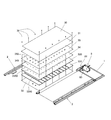
- the treadmill is located on a machine base consisting of a front base 1 and left and right side frames 2, a support plate 3 supported between the left and right side frames 2, and is located in front of the support plate 3 and rotates on the front base 1.
- a front roller (driving roller) 4 that can be provided, a rear roller (driven roller) 5 that is located behind the support plate 3 and is rotatably provided between the left and right side frames 2, a front roller 4 and a rear roller 5
- It is provided with an endless belt (running belt) 6 which is wound around the support plate 3 and runs above and below the support plate 3.
- the endless belt 6 is, for example, a flexible resin endless belt having an upper portion 60 running on the upper side of the support plate 3 and a lower portion 61 running on the lower side of the support plate 3. It includes a front winding portion 62 wound around the front roller 4 and a rear winding portion 63 wound around the rear roller 5.
- the upper portion 60 of the endless belt 6 forms a walking surface or a running surface on which the object rests.
- the front roller 4 has a larger diameter than the rear roller 5, and a pressing roller 7 is provided between the front end of the support plate 3 and the front roller 4 diagonally above the front end of the support plate 3.
- the upper portion 60 of the endless belt 6 extends horizontally in the front-rear direction, and the transition portion 64 between the upper portion 60 and the front winding portion 62 is pressed downward by the pressing roller 7 and is inclined upward toward the front. It is extending.
- the upper portion 60 and the lower portion 61 are parallel to each other at a narrow interval (smaller than the diameter of the front roller 4). Extends to.
- a drive mechanism 8 including a drive motor 80 and a transmission mechanism 81 is mounted on the front base 1.
- the endless belt 6 travels by transmitting the rotational force of the drive motor 80 to the front roller 4 by the transmission mechanism 81. It has become like.
- the drive mechanism 8 is covered with a cover 82.
- a front frame 9 is erected at the front ends of the left and right side frames 2.
- the front frame 9 includes a front support column 90 that stands up at the front ends of the left and right side frames 2, and an upper frame 91 that connects the upper ends of the front support columns 90.
- the upper frame 91 has a display unit 92 and an operation unit 93. It is provided.
- the handrail frame 10 is provided on the side portion of the left and right side frames 2.
- the handrail frame 10 includes front and rear columns 100 and 101, and a handrail bar 102 that connects the front and rear columns 100 and 101.
- the shapes and configurations of the front frame 9 and the handrail frame 10 are not limited to those shown in the drawings.
- the side frame 2 is a long member extending in the front-rear direction, and includes a lower side frame main body 20 and an upper side cover 21.
- the side frame body 20 and the side cover 21 are made of aluminum.
- a resin side step 22 is provided on the upper surface of the side cover 21, and a rubber frame rubber 23 is provided below the side frame main body 20.
- the shape and configuration of the side frame 2 are not limited to those shown in the drawing, and the materials of the elements constituting the side frame 2 are also not limited.
- the support plate 3 is composed of an uppermost layer 30 located directly below the upper portion of the endless belt 6 and having the upper portion running on the uppermost portion, and a base plate 3'located below the uppermost layer 30.
- the base plate 3' according to the present embodiment is wider than the uppermost layer 30, and both ends of the base plate 3'in the width direction are exposed without being covered by the uppermost layer 30.
- the support plate 3 is fixed to the side frame main body 20 by mounting bolts 24 in a state where the lower surfaces of both ends in the width direction of the base plate 3'are placed on the horizontal support surface 200 of the side frame main body 20. As shown in FIG. 2, the mounting bolts 24 penetrate the base plate 3'at both ends in the width direction, but do not penetrate the uppermost layer 30.
- the uppermost layer 30 of the support plate 3 forms a sliding contact surface, and the support plate 3 is located between the upper portion 60 and the lower portion 61 of the endless belt 6 and slides the upper portion 60 of the endless belt 6. I will accept it as much as possible.
- the uppermost layer 30 of the support plate 3 is formed of a material having good slipperiness, and is formed, for example, by impregnating the surface of a wooden sheet whose surface has been polished with silicon or the like.
- the base plate 3' consists of an upper metal sheet 31, a lower metal sheet 32, and an intermediate layer 33 sandwiched between the upper and lower metal sheets 31, 32. ..
- the material of the intermediate layer 33 is not limited, but is formed from, for example, one or more veneer plates.
- the treadmill according to this embodiment has a low profile, that is, a thin shape.
- the thickness of the support plate 3 is at least 20 mm or less.
- the pressing roller 7 can keep the distance between the upper portion 60 and the lower portion 61 of the endless belt 6 smaller than the diameter of the front roller 4, and together with the small diameter rear roller 5 and the thin support plate 3, An overall thin treadmill is provided.
- the height from the floor surface on which the treadmill is installed to the upper portion 60 (walking surface or running surface) of the endless belt 6 is set to 40 mm or less, for example, 35 mm.
- the treadmill can be made thinner by using the pressing roller 7, but the driving means of the endless belt 6 is not limited to the one using the pressing roller 7.
- the present invention is not limited to the thin treadmill, and can be widely applied to the treadmill in general.
- FIG. 4 shows another aspect of the thin treadmill, which includes two endless belts running in parallel (right foot endless belt 6A, left foot endless belt 6B).
- the handrail frame 10' consists of the front and rear columns 100'and 101'and the handrail bars 102'connecting the front and rear columns 100'and 101', and the upper portions of the left and right front columns 100'are flat. It is connected by a U-shaped connection frame 103', and a front bar 104'is provided so as to bridge the front ends of the left and right handrail bars 102'.
- the shape and configuration of these frames are examples.
- the tread mill itself provided with the right foot endless belt 6A and the left foot endless belt 6B is known and is disclosed in, for example, Patent Document 2 and Patent Document 7, and the specific configuration is described in Patent Document 2 and Patent Document. The description of 7 can be referred to.
- the treadmill according to this embodiment is located below the endless belt 6 wound around the front roller 4 and the rear roller 5 and the upper portion 60 of the endless belt 6.
- the target is the upper portion 60 of the endless belt 6 inside or / or on the surface of the support plate 3.
- a plurality of piezoelectric elements P are provided so as to detect the force acting on the support plate 3 from the upper portion 60 of the endless belt 6 when walking or running on the treadmill.
- the support plate 3 is composed of an upper portion 3A and a lower portion 3B, and the plurality of piezoelectric elements P act on the upper surface of the upper portion 3A. It is provided between the upper portion 3A and the lower portion 3B so as to detect the force.
- the upper portion 3A of the support plate 3 comprises an upper surface and a lower surface facing the upper portion 60 of the endless belt 6, and the lower portion 3B comprises an upper surface and a lower surface.
- the piezoelectric element P is provided located between the lower surface of the upper portion 3A and the upper surface of the lower portion 3B.
- the upper portion 3A of the support plate 3 is formed of one or more sheets
- the lower portion 3B of the support plate 3 is formed of one or more sheets.
- the piezoelectric element P is fixed to the lower surface of the upper portion 3A or / and the upper surface of the lower portion 3B in an immovable state (including fixing by a pinching force such as adhesion).
- the upper portion 3A of the support plate 3 is composed of an upper wooden sheet forming the uppermost layer 30 and a lower metal (for example, iron or steel) sheet 31. It is formed by bonding.
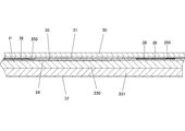
- the lower portion 3B of the support plate 3 is the highest metal (for example, iron or steel) sheet 34, the middle two wooden sheets (for example, veneer plate) 330, 331, and the lowest metal. It is formed by adhering the sheet 32.
- metal for example, iron or steel
- the middle two wooden sheets for example, veneer plate
- a metal (for example, iron, steel, or aluminum) intermediate sheet 35 is provided between the lower surface of the upper portion 3A of the support plate 3 and the upper surface of the lower portion 3B. Be done.
- a plurality of openings 350 are formed at predetermined positions of the intermediate sheet 35, and the piezoelectric element P is housed in each opening 350. More specifically, the upper surface of the lower portion 3B of the support plate 3 forms the bottom surface of the opening 350 formed in the intermediate sheet 35, and the piezoelectric element P is located in the opening 350 and is below the support plate 3. It is fixed (for example, bonded) while being placed on the upper surface of the side portion 3B.
- the height (thickness) of the piezoelectric element P is slightly smaller than the plate thickness of the intermediate sheet 35, and the pusher 36 is arranged on the upper surface of the piezoelectric element P housed in the opening 350 of the intermediate sheet 35. ..
- the pusher 36 is fixed (adhered, etc.) to the upper surface of the piezoelectric element P.
- the shape of the pusher 36 is not limited, but is, for example, a thin disk, the lower surface of the pusher 36 abuts on the upper surface of the piezoelectric element P, and the lower surface of the upper portion 3A abuts on the upper surface of the pusher 36.
- the pusher 36 is located in the opening 350, the upper portion is located above the upper surface of the intermediate sheet 35, and the lower surface of the upper portion 3A of the support plate 3 and the upper surface of the lower portion 3B. Are slightly separated from each other to form a gap G (see FIG. 8).
- the pusher 36 is formed of an insulator, for example made of resin.
- a plurality of spacers 37 are provided between the lower surface of the upper portion 3A of the support plate 3 and the upper surface of the intermediate sheet 35, for example, along the peripheral edge including the corner portion, so as to secure the gap G. I have to.
- the intermediate sheet 35 is provided with a large number of openings 350, only some of the openings 350 are provided with the piezoelectric element P, and the other remaining openings 350 are not provided with the piezoelectric element P.
- a predetermined opening 350 is selected, and the piezoelectric element P is housed in the selected opening 350.
- a dummy plate 38 is housed in the opening 350 in which the piezoelectric element P is not housed so as to fill the opening 350.
- the dummy plate 38 has the same height as the piezoelectric element P, and a pusher 36 is provided between the upper surface of the dummy plate 38 and the lower surface of the upper portion 3A.
- the dummy plate 38 is made of the same material as the intermediate sheet 35, for example, if the intermediate sheet 35 is made of iron, the dummy plate 35 is made of iron.
- the uppermost metal sheet 34 of the lower portion 3B forming the bottom surface of the opening 350 of the intermediate sheet 35 is formed with a perforation 340 located at the bottom surface, and the wooden sheet 330 directly below the metal sheet 34 has a perforation 340.
- the perforation 3300 is formed corresponding to the perforation 340.
- a groove 3310 is formed on the upper surface of the wooden sheet 331 directly below the wooden sheet 330, which is located below the perforation 3300.
- the perforations 340, perforations 3300, and grooves 3310 formed in the lower portion 3B of the support plate 3 form a wiring path for the piezoelectric element P. In the aspect shown in FIG.
- the groove 3310 extends over the entire width of the support plate 3, and the wiring (not shown) guided by the groove 3310 is, for example, a space in one or both side frames 2. Through, for example, it is connected to a processing unit (not shown) provided on the front base 1.
- the direction in which the groove 3310 extends is not limited to the width direction as shown in the drawing, and the layer and position in which the perforations and grooves are formed in the support plate 3 are not limited.
- the support plates 3 are, in order from the top, a wooden sheet (top layer 30), a metal sheet 31, a metal intermediate sheet 35, a metal sheet 34, and a wooden sheet 330. , Wooden sheet 331 and metal sheet 32 are overlapped with each other.
- the upper portion 3A of the support plate 3 is formed by bonding the wooden sheet (top layer 30) and the metal sheet 31 with an adhesive.
- the lower portion 3B of the support plate 3 is formed by bonding the metal sheet 34, the wooden sheet 330, the wooden sheet 331, and the metal sheet 32 with an adhesive.
- the upper portion 3A and the lower portion 3B are fixed with screws 39 with the intermediate sheet 35 sandwiched between the lower surface of the upper portion 3A and the upper surface of the lower portion 3B.
- the screw 39 for integrating the support plate 3 and a part or all of the mounting bolts 24 for fixing the support plate 3 to the side frame 2 may be used in combination.
- the metal sheet 31, the metal intermediate sheet 35, the metal sheet 34, the wooden sheet 330, the wooden sheet 331, and the metal sheet 32 form the base plate 3'of the support plate 3, and the base is formed.
- the uppermost layer 30 made of a wooden sheet is formed on the upper surface of the plate 3'.
- each sheet forming the support plate 3 is, for example, 1 mm to 3 mm for the wooden sheet (top layer 30), the metal sheet 31, the metal intermediate sheet 35, the metal sheet 34, and the metal sheet 32.
- the wooden sheet 330 and the wooden sheet 331 are about 5 mm.
- the wooden sheet (top layer 30) has a thickness of 1 mm or less, and the metal sheet 31 prevents deformation (warping) of the wooden sheet (that is, the wooden sheet and the metal sheet 31 itself. It has the strength (which can maintain the flatness of).
- the warpage of the wooden sheet and the metal sheet 31 is regulated by attracting the metal sheet 31 (made of iron or steel) forming the lower surface of the upper portion 3A of the support plate 3 to the lower portion 3B by magnetic force. May be good.
- the magnet is provided, for example, on the metal sheet 34 of the lower portion 3B, but the magnet may be provided on the intermediate sheet 35, or the metal sheet 31 may be provided with magnetic coating to provide the intermediate sheet 35 (iron or steel).
- the metal sheet 34 (made of iron or steel) of the lower portion 3B may be adsorbed.
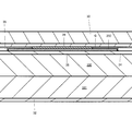
- FIG. 10 shows a non-limiting variation of a mode in which a plurality of piezoelectric elements P are provided between the upper portion 3A and the lower portion 3B of the support plate 3.
- the piezoelectric element P may be provided in such a manner that the force acting on the support plate 3 can be detected from the upper portion 60 of the endless belt 6.
- the embodiment is not limited to the embodiment shown in FIGS. 5 to 9.
- the plurality of piezoelectric elements P are preferably provided at the same depth position and separated from each other in the plane direction (direction parallel to the XY plane) of the support plate 3.
- the lower surface of the piezoelectric element is in contact with the upper surface of the lower portion 3B, and the lower surface of the upper portion 3A is in contact with the upper surface of the piezoelectric element.
- Spacers 37 are provided on the lower surface of the upper portion 3A and the peripheral edge of the upper surface of the lower portion 3B.
- the embodiment shown in FIG. 10B is similar to the above-described embodiment shown in FIGS. 5 to 9, and an intermediate sheet 35 is provided between the upper portion 3A and the lower portion 3B, and the intermediate sheet 35 is provided.
- a plurality of openings are formed in the piezoelectric element, and each piezoelectric element is housed in each opening.
- Pushers 36 and spacers 37 as described in the embodiments shown in FIGS. 5 to 9 may be provided. Instead of the pusher, a downward convex portion may be integrally formed on the lower surface of the upper portion 3A.
- a downward recess is formed on the lower surface of the upper portion 3A, the lower surface of the piezoelectric element P is in contact with the upper surface of the lower portion 3B, and the upper surface of the piezoelectric element P is formed. Is in contact with the lower surface of the upper portion 3A (the upper surface of the downward recess).
- an upward recess is formed on the lower surface of the upper portion 3A, a downward recess is formed on the upper surface of the lower portion 3B, and the lower surface of the piezoelectric element P is formed.
- a downward convex portion is formed on the lower surface of the upper portion 3A
- an upward concave portion is formed on the upper surface of the lower portion 3B
- the lower surface of the piezoelectric element P is formed.
- the upper surface of the lower portion 3B is in contact with the upper surface (lower surface of the upward concave portion), and the upper surface is in contact with the lower surface (downward convex portion) of the upper portion 3A.
- the lower surface of the upper portion 3A and / and the upper surface of the lower portion 3B do not have to be a flat flat surface as a whole, and a portion where the piezoelectric element P is provided. May be concave or convex. Also in the embodiment shown in FIGS. 10 (C) to 10 (E), the pusher 36 and the spacer 37 as described in the embodiments shown in FIGS. 5 to 9 may be provided.
- the support plate 3 has a base plate 3'(lower portion 3B) and an uppermost layer 30 (upper portion 3A) provided so as to cover the upper surface of the base plate 3'.
- a plurality of piezoelectric elements P are provided between the upper surface of the base plate 3'and the lower surface of the uppermost layer 30. More specifically, a plurality of piezoelectric elements P are fixed (adhesive or the like) at predetermined positions on the upper surface of the base plate 3', and the uppermost layer 30 covers the upper surfaces of the piezoelectric element P and the base plate 3'.
- the uppermost layer 30 is formed of a highly slippery resin film or the like.
- the piezoelectric element P is fixed to the lower surface of the upper portion 3A and / or the upper surface of the lower portion 3B in an immovable state (including fixing by a pinching force such as adhesion).
- the wiring for outputting the signal from the piezoelectric element P is omitted.
- the output of the signal from the piezoelectric element P is not limited to the one using a wire, and may be output wirelessly.
- the plurality of piezoelectric elements P may be integrally formed on the flexible substrate, and the signal from the piezoelectric element P may be output via the flexible substrate.
- a flexible substrate provided with the piezoelectric element P may be provided between the upper portion 3A and the lower portion 3B of the support plate 3.
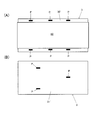
- the support plate 3 includes a portion facing the upper portion 60 of the endless belt 6 and a non-opposing portion not facing the upper portion 60 of the endless belt 6.
- the upper surface of the support plate 3 includes a portion facing the upper portion 60 of the endless belt 6.
- a plurality of piezoelectric elements P are provided on the surface of a non-opposing portion that does not face the upper portion 60 of the endless belt 6. The piezoelectric element P detects the vibration of the support plate 3 when a force acts on the support plate 3.
- the width of the upper surface of the support plate 3 (base plate 3') is larger than the width of the endless belt 6 (upper portion 60), and the widthwise side portions 30'of the upper surface are , It is a non-opposing portion that is not located below the upper portion 60 of the endless belt 6.
- a plurality of piezoelectric elements P are fixed (adhered or the like) to both side portions 30'(non-opposing portions) in the width direction on the upper surface of the support plate 3.
- FIG. 11B shows a mode in which a plurality of piezoelectric elements P are fixed (adhered or the like) to the lower surface 31'of the support plate 3 (base plate 3').
- the left and right independent endless belts 6A and 6B are provided (see FIG. 4), and they are located between the upper parts of the left and right endless belts 6A and 6B and do not face the upper parts 60 of the endless belts 6A and 6B.
- a piezoelectric element may be provided at such a portion.
- the piezoelectric element P detects the vibration of the support plate 3 when a force acts on the support plate 3, and in one embodiment, the plurality of piezoelectric elements P are in contact with only the support plate 3.
- Contacting only the support plate means that the structure other than the support plate of the treadmill and the floor surface are not in contact with each other, and that the piezoelectric element P is in contact with the means for fixing the piezoelectric element P to the support plate 3. Is not excluded.
- the surface of the support plate 3 may be provided with an element that protects the piezoelectric element P provided on the surface of the support plate 3.
- the piezoelectric element P detects the vibration transmitted from the frame such as the handrail to the support plate 3, but the output voltage (signal) due to the vibration other than walking is converted into data by an experiment in advance, and the vibration other than walking is performed.
- the output voltage from the piezoelectric element P may be corrected by canceling the noise caused by the vibration.
- the piezoelectric element is an element that converts the force applied to the piezoelectric body into a voltage, and converts the force acting on the support plate 3 into a voltage and outputs it.
- Examples of the piezoelectric element include a piezoelectric vibrating plate (a piezoelectric element bonded to a metal plate such as brass or nickel), a piezoelectric ceramic, a crystalline piezoelectric element, and an element in which a soft magnetic material and a magnetic strain material are bonded (see WO2018 / 230154). can do.
- the thickness of the piezoelectric element is not limited, but is preferably 1 mm or less, more preferably 0.6 mm or less (confirmation required).
- the piezoelectric element may be a sheet body (for example, formed from a flexible substrate) in which a plurality of piezoelectric elements are arranged in an array.
- the piezoelectric element detects the vibration of the support plate and is an ultra-thin film having flexibility (for example, a piezoelectric PVDF polymer film).
- FIG. 12 shows the flow of the signal acquired by the piezoelectric element.
- a force acts on the support plate 3 located directly below the upper portion 60.
- the force acting on the support plate 3 is detected by a plurality of piezoelectric elements P provided on the support plate 3, and a signal (output voltage) is output from each piezoelectric element P and transmitted to the processing unit by wire or wirelessly.
- a predetermined calculation is executed using the output voltages from the plurality of received piezoelectric elements P, and the processing data is output.
- the processing unit may be mounted on the treadmill or may be provided separately from the treadmill.
- the piezoelectric element P detects a force in the vertical direction, and the processed data can be used in combination with, for example, other measurement data (for example, target operation data).
- other measurement data for example, target operation data.
Landscapes
- Health & Medical Sciences (AREA)
- General Health & Medical Sciences (AREA)
- Physical Education & Sports Medicine (AREA)
- Physics & Mathematics (AREA)
- Cardiology (AREA)
- Vascular Medicine (AREA)
- General Physics & Mathematics (AREA)
- Spectroscopy & Molecular Physics (AREA)
- Rehabilitation Tools (AREA)
- Measurement Of The Respiration, Hearing Ability, Form, And Blood Characteristics Of Living Organisms (AREA)
Priority Applications (3)
| Application Number | Priority Date | Filing Date | Title |
|---|---|---|---|
| CN202080063244.8A CN114364437A (zh) | 2019-09-12 | 2020-09-03 | 跑步机 |
| US17/642,114 US20230310927A1 (en) | 2019-09-12 | 2020-09-03 | Treadmill |
| EP20863305.7A EP4029574A4 (en) | 2019-09-12 | 2020-09-03 | CONVEYOR BELT |
Applications Claiming Priority (2)
| Application Number | Priority Date | Filing Date | Title |
|---|---|---|---|
| JP2019-166013 | 2019-09-12 | ||
| JP2019166013A JP7327793B2 (ja) | 2019-09-12 | 2019-09-12 | トレッドミル |
Publications (1)
| Publication Number | Publication Date |
|---|---|
| WO2021049417A1 true WO2021049417A1 (ja) | 2021-03-18 |
Family
ID=74863255
Family Applications (1)
| Application Number | Title | Priority Date | Filing Date |
|---|---|---|---|
| PCT/JP2020/033453 Ceased WO2021049417A1 (ja) | 2019-09-12 | 2020-09-03 | トレッドミル |
Country Status (6)
| Country | Link |
|---|---|
| US (1) | US20230310927A1 (https=) |
| EP (1) | EP4029574A4 (https=) |
| JP (1) | JP7327793B2 (https=) |
| CN (1) | CN114364437A (https=) |
| TW (1) | TWI833989B (https=) |
| WO (1) | WO2021049417A1 (https=) |
Families Citing this family (3)
| Publication number | Priority date | Publication date | Assignee | Title |
|---|---|---|---|---|
| US20240269508A1 (en) * | 2023-02-14 | 2024-08-15 | Lana Schlosser | Partner Treadmill Device |
| IT202300002868A1 (it) * | 2023-02-20 | 2024-08-20 | Technogym Spa | Metodo di determinazione di informazioni rappresentative dell’interazione di un utente con una superficie di esercizio fisico di un tappeto rotante e relativo tappeto rotante |
| CN117101085A (zh) * | 2023-10-13 | 2023-11-24 | 浙江麦瑞克供应链管理有限公司 | 一种跑步机 |
Citations (14)
| Publication number | Priority date | Publication date | Assignee | Title |
|---|---|---|---|---|
| JPS5930389B2 (ja) | 1981-08-20 | 1984-07-26 | 日本水産株式会社 | リング状イカ食品の製造方法 |
| US4830021A (en) | 1988-08-29 | 1989-05-16 | Thornton William E | Monitoring system for locomotor activity |
| JPH09122269A (ja) * | 1995-10-31 | 1997-05-13 | Hitachi Techno Eng Co Ltd | 走行・運動訓練装置 |
| US6010465A (en) | 1991-10-10 | 2000-01-04 | Neurocom International, Inc. | Apparatus and method for characterizing gait |
| US6173608B1 (en) | 1995-02-08 | 2001-01-16 | Centre Stephanois De Recherches Mechaniques Hydromecanique Et Frottement S.A. | Device for measuring forces exerted during ambulatory exercise |
| JP2002085586A (ja) | 2000-09-12 | 2002-03-26 | Otake Route Kogyo:Kk | ランニングマシン |
| JP2005245900A (ja) | 2004-03-08 | 2005-09-15 | Otake Route Kogyo:Kk | ランニングマシン |
| US8002672B2 (en) | 2007-10-15 | 2011-08-23 | Zebris Medical Gmbh | Gait analysis apparatus and method using a treadmill |
| JP6187208B2 (ja) | 2013-12-05 | 2017-08-30 | トヨタ自動車株式会社 | 歩行リハビリシステム |
| WO2018118687A1 (en) * | 2016-12-22 | 2018-06-28 | OntheMuv, Inc. | Seated treadmill and method of use |
| JP2018121962A (ja) | 2017-02-02 | 2018-08-09 | 株式会社大武ルート工業 | 低床トレッドミル |
| CN108452480A (zh) * | 2018-04-11 | 2018-08-28 | 杭州启望科技有限公司 | 一种跑步机及跑步机上跑步姿势的检测方法和装置 |
| JP2018139975A (ja) | 2017-02-28 | 2018-09-13 | 国立大学法人大阪大学 | 歩行訓練装置、歩行診断装置、体重免荷装置、歩行訓練方法、及び歩行診断方法 |
| WO2018230154A1 (ja) | 2017-06-16 | 2018-12-20 | 国立大学法人東北大学 | エネルギー変換部材、振動発電装置、力センサー装置およびアクチュエータ |
Family Cites Families (30)
| Publication number | Priority date | Publication date | Assignee | Title |
|---|---|---|---|---|
| US5314391A (en) * | 1992-06-11 | 1994-05-24 | Computer Sports Medicine, Inc. | Adaptive treadmill |
| US5299454A (en) * | 1992-12-10 | 1994-04-05 | K.K. Holding Ag | Continuous foot-strike measuring system and method |
| US5368532A (en) * | 1993-02-03 | 1994-11-29 | Diversified Products Corporation | Treadmill having an automatic speed control system |
| AT398905B (de) * | 1993-04-21 | 1995-02-27 | Gruenangerl Johann | Feststehende unterlage für ein förderband für personen |
| JP3153744B2 (ja) * | 1995-09-26 | 2001-04-09 | 日立テクノエンジニアリング株式会社 | 走者応答運動装置 |
| ES2192482B1 (es) * | 2002-03-13 | 2005-02-16 | Miguel Jimenez Laso | Aparato gimnastico y deportivo con pantalla de proyeccion estereoscopica. |
| CN1206007C (zh) * | 2002-10-31 | 2005-06-15 | 威盛电子股份有限公司 | 压力感应式虚拟实境跑步机 |
| KR20060001884A (ko) * | 2005-12-06 | 2006-01-06 | 경북대학교 산학협력단 | 런닝머신 및 그 제어방법 |
| US7101319B1 (en) * | 2006-01-27 | 2006-09-05 | Potts Mark J | Multiple pressure sensor speed controlled treadmill |
| KR100702898B1 (ko) * | 2006-05-29 | 2007-04-03 | 경북대학교 산학협력단 | 동작분석을 이용한 보행훈련 장치 |
| KR100716708B1 (ko) * | 2006-07-11 | 2007-05-09 | 영남대학교 산학협력단 | 압력센서 어레이를 이용한 속도조절 런닝머신 및 그동작방법 |
| US7914420B2 (en) * | 2007-07-18 | 2011-03-29 | Brunswick Corporation | Sensing applications for exercise machines |
| ATE512624T1 (de) * | 2007-11-14 | 2011-07-15 | Zebris Medical Gmbh | Anordnung zur ganganalyse |
| NL1035236C2 (nl) * | 2008-03-31 | 2009-10-01 | Forcelink B V | Inrichting en werkwijze voor het aanbieden van doelindicaties voor voetplaatsing aan personen met een loopstoornis. |
| US8480541B1 (en) * | 2009-06-23 | 2013-07-09 | Randall Thomas Brunts | User footfall sensing control system for treadmill exercise machines |
| US8007408B1 (en) * | 2009-10-05 | 2011-08-30 | Johnson Health Tech Co., Ltd. | Treadmill speed control system |
| IT1404711B1 (it) * | 2011-02-04 | 2013-11-29 | Milano Politecnico | Apparato e metodo e per la localizzazione del punto d impatto di un corpo su una superficie |
| US9517378B2 (en) * | 2011-08-03 | 2016-12-13 | Icon Health & Fitness, Inc. | Treadmill with foot fall monitor and cadence display |
| US20130274067A1 (en) * | 2011-09-01 | 2013-10-17 | Icon Health & Fitness, Inc. | System and method for simulating environmental conditions on an exercise device |
| EP2753242A4 (en) * | 2011-09-08 | 2015-01-14 | Paofit Holdings Pte Ltd | SENSOR DEVICE AND SYSTEM FOR PHYSICAL CONDITIONING EQUIPMENT |
| DE102012212115B3 (de) * | 2012-07-11 | 2013-08-14 | Zebris Medical Gmbh | Laufbandanordnung und Verfahren zum Betrieb einer solchen |
| US10421002B2 (en) * | 2013-03-11 | 2019-09-24 | Kelly Ann Smith | Equipment, system and method for improving exercise efficiency in a cardio-fitness machine |
| WO2015003211A1 (en) * | 2013-07-12 | 2015-01-15 | Royal Melbourne Institute Of Technology | Sensor array system |
| US9950213B2 (en) * | 2013-09-17 | 2018-04-24 | Robert Albert Skulman | Systems and methods for deliberate stride over-extension |
| US9808672B2 (en) * | 2014-07-25 | 2017-11-07 | Icon Health & Fitness, Inc. | Position sensor on a treadmill |
| WO2016014588A1 (en) * | 2014-07-25 | 2016-01-28 | Icon Health & Fitness, Inc. | Determining work performed on a treadmill |
| US10674958B2 (en) * | 2014-09-29 | 2020-06-09 | Pulson, Inc. | Systems and methods for coordinating musculoskeletal and cardiovascular hemodynamics |
| EP3374041A4 (en) * | 2015-11-14 | 2019-12-04 | Jordan Frank | TRAINING TREADMILL |
| US10987544B2 (en) * | 2016-05-02 | 2021-04-27 | Southern Research Institute | Force profile control for the application of horizontal resistive force |
| CN108744402A (zh) * | 2018-06-28 | 2018-11-06 | 池州市尔文软件开发有限公司 | 一种家用跑步机 |
-
2019
- 2019-09-12 JP JP2019166013A patent/JP7327793B2/ja active Active
-
2020
- 2020-09-03 WO PCT/JP2020/033453 patent/WO2021049417A1/ja not_active Ceased
- 2020-09-03 CN CN202080063244.8A patent/CN114364437A/zh active Pending
- 2020-09-03 US US17/642,114 patent/US20230310927A1/en not_active Abandoned
- 2020-09-03 EP EP20863305.7A patent/EP4029574A4/en not_active Withdrawn
- 2020-09-07 TW TW109130583A patent/TWI833989B/zh active
Patent Citations (14)
| Publication number | Priority date | Publication date | Assignee | Title |
|---|---|---|---|---|
| JPS5930389B2 (ja) | 1981-08-20 | 1984-07-26 | 日本水産株式会社 | リング状イカ食品の製造方法 |
| US4830021A (en) | 1988-08-29 | 1989-05-16 | Thornton William E | Monitoring system for locomotor activity |
| US6010465A (en) | 1991-10-10 | 2000-01-04 | Neurocom International, Inc. | Apparatus and method for characterizing gait |
| US6173608B1 (en) | 1995-02-08 | 2001-01-16 | Centre Stephanois De Recherches Mechaniques Hydromecanique Et Frottement S.A. | Device for measuring forces exerted during ambulatory exercise |
| JPH09122269A (ja) * | 1995-10-31 | 1997-05-13 | Hitachi Techno Eng Co Ltd | 走行・運動訓練装置 |
| JP2002085586A (ja) | 2000-09-12 | 2002-03-26 | Otake Route Kogyo:Kk | ランニングマシン |
| JP2005245900A (ja) | 2004-03-08 | 2005-09-15 | Otake Route Kogyo:Kk | ランニングマシン |
| US8002672B2 (en) | 2007-10-15 | 2011-08-23 | Zebris Medical Gmbh | Gait analysis apparatus and method using a treadmill |
| JP6187208B2 (ja) | 2013-12-05 | 2017-08-30 | トヨタ自動車株式会社 | 歩行リハビリシステム |
| WO2018118687A1 (en) * | 2016-12-22 | 2018-06-28 | OntheMuv, Inc. | Seated treadmill and method of use |
| JP2018121962A (ja) | 2017-02-02 | 2018-08-09 | 株式会社大武ルート工業 | 低床トレッドミル |
| JP2018139975A (ja) | 2017-02-28 | 2018-09-13 | 国立大学法人大阪大学 | 歩行訓練装置、歩行診断装置、体重免荷装置、歩行訓練方法、及び歩行診断方法 |
| WO2018230154A1 (ja) | 2017-06-16 | 2018-12-20 | 国立大学法人東北大学 | エネルギー変換部材、振動発電装置、力センサー装置およびアクチュエータ |
| CN108452480A (zh) * | 2018-04-11 | 2018-08-28 | 杭州启望科技有限公司 | 一种跑步机及跑步机上跑步姿势的检测方法和装置 |
Non-Patent Citations (1)
| Title |
|---|
| See also references of EP4029574A4 |
Also Published As
| Publication number | Publication date |
|---|---|
| TWI833989B (zh) | 2024-03-01 |
| TW202110508A (zh) | 2021-03-16 |
| JP7327793B2 (ja) | 2023-08-16 |
| JP2021041007A (ja) | 2021-03-18 |
| US20230310927A1 (en) | 2023-10-05 |
| CN114364437A (zh) | 2022-04-15 |
| EP4029574A4 (en) | 2023-10-04 |
| EP4029574A1 (en) | 2022-07-20 |
Similar Documents
| Publication | Publication Date | Title |
|---|---|---|
| WO2021049417A1 (ja) | トレッドミル | |
| US9753536B2 (en) | Electronic device | |
| CN105304072B (zh) | 电子打击乐器用踏板装置 | |
| US20060219445A1 (en) | Wheelchair scale | |
| CN101910812A (zh) | 载荷传感器 | |
| JP7625969B2 (ja) | 電子機器 | |
| JP2021041007A5 (https=) | ||
| HK40073169A (en) | Treadmill | |
| US7714486B2 (en) | Angular velocity sensor and angular velocity sensing device | |
| KR102458682B1 (ko) | 라미네이팅 장치 및 라미네이팅 방법 | |
| EP3866156B1 (en) | Impact detection device and percussion instrument | |
| JP3624459B2 (ja) | 人体検出装置 | |
| JPH0349733A (ja) | 圧脈波検出装置 | |
| JP3444810B2 (ja) | シート重量計測装置 | |
| JP5895710B2 (ja) | 電子打楽器用のペダル装置 | |
| KR20200079153A (ko) | 플렉서블 디스플레이 모듈 및 이를 포함하는 전자장치 | |
| JP2008516717A (ja) | 両脚によってもたらされる力を測定及び分析する装置 | |
| JP3663406B2 (ja) | シート重量計測装置 | |
| JP2005188951A (ja) | 動釣合試験機 | |
| JP2006010407A (ja) | すべり覚検出センサ | |
| KR20180083006A (ko) | 트레드밀 | |
| CN1812735A (zh) | 带就座传感器的座席及座席用衬垫 | |
| JP7601269B2 (ja) | センサ及びセンサの製造方法 | |
| JP5374117B2 (ja) | ピアノの棚板 | |
| JP7476860B2 (ja) | 検出装置及び履物 |
Legal Events
| Date | Code | Title | Description |
|---|---|---|---|
| 121 | Ep: the epo has been informed by wipo that ep was designated in this application |
Ref document number: 20863305 Country of ref document: EP Kind code of ref document: A1 |
|
| NENP | Non-entry into the national phase |
Ref country code: DE |
|
| ENP | Entry into the national phase |
Ref document number: 2020863305 Country of ref document: EP Effective date: 20220412 |