WO2021049109A1 - 水分検知装置 - Google Patents
水分検知装置 Download PDFInfo
- Publication number
- WO2021049109A1 WO2021049109A1 PCT/JP2020/022418 JP2020022418W WO2021049109A1 WO 2021049109 A1 WO2021049109 A1 WO 2021049109A1 JP 2020022418 W JP2020022418 W JP 2020022418W WO 2021049109 A1 WO2021049109 A1 WO 2021049109A1
- Authority
- WO
- WIPO (PCT)
- Prior art keywords
- light
- detection device
- light source
- wavelength
- moisture detection
- Prior art date
- Legal status (The legal status is an assumption and is not a legal conclusion. Google has not performed a legal analysis and makes no representation as to the accuracy of the status listed.)
- Ceased
Links
Images





Classifications
-
- G—PHYSICS
- G01—MEASURING; TESTING
- G01N—INVESTIGATING OR ANALYSING MATERIALS BY DETERMINING THEIR CHEMICAL OR PHYSICAL PROPERTIES
- G01N21/00—Investigating or analysing materials by the use of optical means, i.e. using sub-millimetre waves, infrared, visible or ultraviolet light
- G01N21/17—Systems in which incident light is modified in accordance with the properties of the material investigated
- G01N21/25—Colour; Spectral properties, i.e. comparison of effect of material on the light at two or more different wavelengths or wavelength bands
- G01N21/31—Investigating relative effect of material at wavelengths characteristic of specific elements or molecules, e.g. atomic absorption spectrometry
-
- G—PHYSICS
- G01—MEASURING; TESTING
- G01N—INVESTIGATING OR ANALYSING MATERIALS BY DETERMINING THEIR CHEMICAL OR PHYSICAL PROPERTIES
- G01N21/00—Investigating or analysing materials by the use of optical means, i.e. using sub-millimetre waves, infrared, visible or ultraviolet light
- G01N21/17—Systems in which incident light is modified in accordance with the properties of the material investigated
- G01N21/25—Colour; Spectral properties, i.e. comparison of effect of material on the light at two or more different wavelengths or wavelength bands
- G01N21/31—Investigating relative effect of material at wavelengths characteristic of specific elements or molecules, e.g. atomic absorption spectrometry
- G01N21/35—Investigating relative effect of material at wavelengths characteristic of specific elements or molecules, e.g. atomic absorption spectrometry using infrared light
- G01N21/3554—Investigating relative effect of material at wavelengths characteristic of specific elements or molecules, e.g. atomic absorption spectrometry using infrared light for determining moisture content
-
- G—PHYSICS
- G01—MEASURING; TESTING
- G01N—INVESTIGATING OR ANALYSING MATERIALS BY DETERMINING THEIR CHEMICAL OR PHYSICAL PROPERTIES
- G01N21/00—Investigating or analysing materials by the use of optical means, i.e. using sub-millimetre waves, infrared, visible or ultraviolet light
- G01N21/17—Systems in which incident light is modified in accordance with the properties of the material investigated
- G01N21/25—Colour; Spectral properties, i.e. comparison of effect of material on the light at two or more different wavelengths or wavelength bands
- G01N21/31—Investigating relative effect of material at wavelengths characteristic of specific elements or molecules, e.g. atomic absorption spectrometry
- G01N21/314—Investigating relative effect of material at wavelengths characteristic of specific elements or molecules, e.g. atomic absorption spectrometry with comparison of measurements at specific and non-specific wavelengths
- G01N21/3151—Investigating relative effect of material at wavelengths characteristic of specific elements or molecules, e.g. atomic absorption spectrometry with comparison of measurements at specific and non-specific wavelengths using two sources of radiation of different wavelengths
-
- G—PHYSICS
- G01—MEASURING; TESTING
- G01N—INVESTIGATING OR ANALYSING MATERIALS BY DETERMINING THEIR CHEMICAL OR PHYSICAL PROPERTIES
- G01N21/00—Investigating or analysing materials by the use of optical means, i.e. using sub-millimetre waves, infrared, visible or ultraviolet light
- G01N21/17—Systems in which incident light is modified in accordance with the properties of the material investigated
- G01N21/25—Colour; Spectral properties, i.e. comparison of effect of material on the light at two or more different wavelengths or wavelength bands
- G01N21/31—Investigating relative effect of material at wavelengths characteristic of specific elements or molecules, e.g. atomic absorption spectrometry
- G01N21/35—Investigating relative effect of material at wavelengths characteristic of specific elements or molecules, e.g. atomic absorption spectrometry using infrared light
- G01N21/359—Investigating relative effect of material at wavelengths characteristic of specific elements or molecules, e.g. atomic absorption spectrometry using infrared light using near infrared light
-
- G—PHYSICS
- G02—OPTICS
- G02B—OPTICAL ELEMENTS, SYSTEMS OR APPARATUS
- G02B27/00—Optical systems or apparatus not provided for by any of the groups G02B1/00 - G02B26/00, G02B30/00
- G02B27/10—Beam splitting or combining systems
- G02B27/14—Beam splitting or combining systems operating by reflection only
- G02B27/141—Beam splitting or combining systems operating by reflection only using dichroic mirrors
-
- G—PHYSICS
- G02—OPTICS
- G02B—OPTICAL ELEMENTS, SYSTEMS OR APPARATUS
- G02B27/00—Optical systems or apparatus not provided for by any of the groups G02B1/00 - G02B26/00, G02B30/00
- G02B27/28—Optical systems or apparatus not provided for by any of the groups G02B1/00 - G02B26/00, G02B30/00 for polarising
- G02B27/283—Optical systems or apparatus not provided for by any of the groups G02B1/00 - G02B26/00, G02B30/00 for polarising used for beam splitting or combining
-
- G—PHYSICS
- G08—SIGNALLING
- G08G—TRAFFIC CONTROL SYSTEMS
- G08G1/00—Traffic control systems for road vehicles
-
- G—PHYSICS
- G01—MEASURING; TESTING
- G01N—INVESTIGATING OR ANALYSING MATERIALS BY DETERMINING THEIR CHEMICAL OR PHYSICAL PROPERTIES
- G01N21/00—Investigating or analysing materials by the use of optical means, i.e. using sub-millimetre waves, infrared, visible or ultraviolet light
- G01N21/17—Systems in which incident light is modified in accordance with the properties of the material investigated
- G01N21/47—Scattering, i.e. diffuse reflection
- G01N2021/4704—Angular selective
- G01N2021/4709—Backscatter
-
- G—PHYSICS
- G01—MEASURING; TESTING
- G01N—INVESTIGATING OR ANALYSING MATERIALS BY DETERMINING THEIR CHEMICAL OR PHYSICAL PROPERTIES
- G01N21/00—Investigating or analysing materials by the use of optical means, i.e. using sub-millimetre waves, infrared, visible or ultraviolet light
- G01N21/17—Systems in which incident light is modified in accordance with the properties of the material investigated
- G01N21/47—Scattering, i.e. diffuse reflection
- G01N21/4738—Diffuse reflection, e.g. also for testing fluids, fibrous materials
- G01N21/474—Details of optical heads therefor, e.g. using optical fibres
-
- G—PHYSICS
- G01—MEASURING; TESTING
- G01N—INVESTIGATING OR ANALYSING MATERIALS BY DETERMINING THEIR CHEMICAL OR PHYSICAL PROPERTIES
- G01N2201/00—Features of devices classified in G01N21/00
- G01N2201/06—Illumination; Optics
- G01N2201/063—Illuminating optical parts
- G01N2201/0636—Reflectors
Definitions
- the present invention relates to a moisture detection device that detects the state of moisture in an object, and is suitable for use, for example, when detecting the state of water, ice, snow, etc. deposited on the road surface.
- a road surface detection device that detects the condition of the road surface.
- an illumination light is applied to a detected area on a road surface, and based on the reflected light, it is determined whether or not an object to be detected such as ice or water exists in the detected area.
- a road surface condition detection device is described.
- the detection light and the reference light having different wavelengths are sequentially switched as the illumination light to irradiate the detected region.
- the reflected light of each light is received and an electric signal is generated. Then, these electric signals are compared and calculated, and based on the calculation result, it is determined whether or not an object to be detected such as water or ice exists in the detected region.
- Patent Document 1 the illumination light and the reflected light are individually irradiated and received by different optical systems in different directions. Therefore, it is necessary to adjust the irradiation angle of the illumination light and the reception angle of the reflected light according to the distance between the road surface condition detection device and the detection area. Such adjustment work is extremely complicated.
- an object of the present invention is to provide a moisture detection device capable of detecting the state of moisture in an object without performing complicated adjustment work.
- the moisture detection device has a light source unit, a projection optical system that projects illumination light emitted from the light source unit onto an object, and reflected light of the illumination light reflected by the object.
- the light detector that receives light
- the light receiving optical system that collects the reflected light on the light detector
- the optical axis of the projection optical system and the optical axis of the light receiving optical system are aligned with each other in the range on the object side. It is provided with an optical element to be operated.
- the moisture detection device since the optical axis of the projection optical system and the optical axis of the light receiving optical system are aligned with each other in the range on the object side, among the reflected light reflected by the object. , The reflected light that reverses the aligned optical axis can be focused on the photodetector by the light receiving optical system. Therefore, it is not necessary to adjust the angle between the illumination light and the reflected light with respect to the object according to the distance between the device and the object, and the reflected light from the object is appropriately measured by the photodetector without such adjustment. Can receive light.
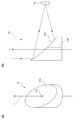
- FIG. 1 is a diagram showing a configuration of an optical system of a moisture detection device according to an embodiment.
- 2A and 2B are perspective views and side views showing the configuration of the optical element according to the embodiment, respectively.
- FIG. 3 is a block diagram showing a configuration of a circuit unit of the moisture detection device according to the embodiment.
- FIG. 4 is a graph showing the light absorption coefficients in water and ice according to the embodiment.
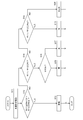
- FIG. 5 is a flowchart showing a determination process of the moisture detection device according to the embodiment.
- FIG. 6A is a diagram schematically showing an example of an installed state of the moisture detection device according to the embodiment.
- FIG. 6B is a graph showing the relationship between the incident angle of light with respect to the water surface and the reflectance according to the embodiment.
- FIG. 7 is a graph showing the relationship between the pulse width and the peak power that satisfy the condition that the laser safety standard is Class 1 according to the embodiment.
- FIG. 8 is a diagram schematically showing a configuration of a road surface information distribution system according to an embodiment.
- FIG. 9 is a diagram showing a configuration of an optical system of the moisture detection device according to the first modification.
- FIG. 10A is a diagram showing a simulation result obtained by simulation of the condensed state of the reflected light when the reflected light is condensed by the photodetector by the condensing lens according to the first modification.
- FIG. 10B is a diagram showing a simulation result obtained by simulation of the condensed state of the reflected light when the reflected light is focused on the photodetector by the reflecting surface having a parabolic surface shape according to the embodiment. is there.
- FIG. 11 is a diagram showing a configuration of an optical system of the moisture detection device according to the second modification.
- FIG. 12 is a diagram showing another configuration of the optical system of the moisture detection device according to the second modification.
- FIG. 13 is a diagram showing a configuration of an optical system of the moisture detection device according to the third modification.
- the present invention is applied to a moisture detection device that detects moisture (water, snow, ice, etc.) accumulated on a road surface which is an object.
- FIG. 1 is a diagram showing a configuration of an optical system of the moisture detection device 1.
- the moisture detection device 1 includes a light source unit 10, a projection optical system 20, a light receiving optical system 30, and a photodetector 40.
- the light source unit 10 emits a plurality of illumination lights L1 having different wavelengths.
- the projection optical system 20 projects the illumination light L1 emitted from the light source unit 10 onto the road surface.
- the photodetector 40 receives the reflected light R1 of the illumination light L1 reflected on the road surface.
- the light source unit 10 includes three light sources 11, 12, and 13 having different wavelengths from each other.
- the light sources 11, 12, and 13 are laser light sources such as a semiconductor laser, for example.
- the light sources 11, 12, and 13 may be composed of an LED or a white light source with a filter that passes through a specific wavelength.
- the light source 11 emits near-infrared light having a wavelength of 980 nm (hereinafter, referred to as “reference wavelength”).
- the light source 12 emits near-infrared light having a wavelength of 1450 nm (hereinafter, referred to as “absorption wavelength 1”).
- the light source 13 emits near-infrared light having a wavelength of 1550 nm (hereinafter, referred to as “absorption wavelength 2”).
- the light sources 12 and 13 emit the illumination light L1 in the same direction, and the light source 11 emits the illumination light L1 in the direction orthogonal to the emission direction of the light sources 12 and 13.
- the emission optical axes of the light sources 11, 12, and 13 are included in the same plane. That is, the emission optical axes of the light source 11 and the emission optical axes of the light sources 12 and 13 are orthogonal to each other.
- the projection optical system 20 includes collimator lenses 21, 22, 23, a dichroic mirror 24, and a polarization beam splitter (hereinafter referred to as “PBS”) 25.
- the collimator lenses 21, 22, and 23 convert the illumination light L1 emitted from the light sources 11, 12, and 13, respectively, into parallel light.
- the dichroic mirror 24 transmits the illumination light L1 emitted from the light source 11 and reflects the illumination light L1 emitted from the light source 12. As a result, the emission light axis of the light source 11 and the emission light axis of the light source 12 are aligned.
- the PBS 25 transmits the two illumination lights L1 incident from the dichroic mirror 24 side and reflects the illumination light L1 emitted from the light source 13. That is, the light sources 11 and 12 are arranged so that the polarization direction is P-polarized with respect to PBS 25, and the light source 13 is arranged so that the polarization direction is S-polarized with respect to PBS 25. As a result, the emission optical axes of the light sources 11, 12, and 13 are aligned with the optical axis A1 of the projection optical system 20.
- the dichroic mirror 24 and the PBS 25 form a matching optical system 20a that aligns the emission optical axes of the light sources 11, 12, and 13 with each other.
- the light receiving optical system 30 includes an optical element 31.
- the optical element 31 aligns the optical axis A1 of the projection optical system 20 and the optical axis A2 of the light receiving optical system 30 with each other in a road surface side range (range from the optical element 31 to the projection direction of the illumination light L1). That is, these two optical axes A1 and A2 are integrated into the common optical axis A10 by the optical element 31.
- the optical element 31 has a reflecting surface 31a on a surface opposite to the projection optical system 20.
- the reflecting surface 31a is a paraboloid recessed inward of the optical element 31.
- the reflecting surface 31a collects the reflected light R1 incident along the optical axis A10 on the light receiving surface of the photodetector 40.
- the optical axis of the reflecting surface 31a is the optical axis A2 of the light receiving optical system 30.
- the optical axis A2 is perpendicular to the optical axis A1 of the projection optical system 20.
- the optical axis A1 and the optical axis A2 do not have to be perpendicular to each other, and may have other angles.
- the shape of the reflecting surface 31a is changed according to the angle between the optical axis A1 and the optical axis A2, and the arrangement of the photodetector 40 is adjusted so that the light receiving surface is perpendicular to the optical axis A2. ..
- 2 (a) and 2 (b) are a perspective view and a side view showing the configuration of the optical element 31.
- the optical element 31 has a shape in which the upper surface of the columnar member is cut out diagonally.
- the optical element 31 is formed with an opening 31b for passing the illumination light L1 projected from the projection optical system 20.
- the opening 31b is formed by a through hole that penetrates the optical element 31 along the central axis of the optical element 31.
- a slit-shaped notch extending from the outer surface of the optical element 31 to the central axis may be formed to provide the opening 31b.
- the illumination light L1 passes through the opening 31b and is projected onto the road surface.
- the reflected light R1 from the road surface is focused on the photodetector 40 by the reflecting surface 31a.
- the photodetector 40 is composed of, for example, a photodiode.
- a photodiode having a detection sensitivity in an infrared wavelength band for example, 900 to 1800 nm
- the light detector 40 transmits the reference wavelength, the absorption wavelength 1 and the absorption wavelength 2, which are the emission wavelengths of the light sources 11, 12, and 13, and blocks the visible light wavelength band.
- the filter to be used may be arranged in front of the light detector 40.
- the photodetector 40 may be composed of an avalanche photodiode.
- the photodetector 40 receives the reflected light R1 reflected on the road surface by the illumination light L1 emitted from the light sources 11, 12, and 13, and outputs an electric signal based on the received light amount.
- the light sources 11, 12, and 13 are driven so as to emit pulses in a time-division manner. Therefore, the photodetector 40 receives the reflected light R1 based on the illumination light L1 from the light sources 11, 12, and 13 in a time-divided manner, and outputs an electric signal corresponding to the received light amount of each reflected light R1.
- the type of deposits (moisture state) on the road surface is determined. The sediment determination process will be described later with reference to FIG.
- FIG. 3 is a block diagram showing a configuration of a circuit unit of the moisture detection device 1.
- the moisture detection device 1 includes a control unit 110, a storage unit 120, an output unit 130, and three drive units 141, 142, and 143. , And a processing unit 150.
- the control unit 110 is composed of, for example, a CPU or a microcomputer.
- the control unit 110 controls each unit in the moisture detection device 1 according to the control program stored in the storage unit 120.
- the determination unit 111 is provided in the control unit 110.
- the determination unit 111 determines the type of deposit (water, snow, ice) on the road surface based on the detection signal from the photodetector 40.
- the determination unit 111 may be configured as hardware instead of a function by the control program.
- the storage unit 120 includes a memory, stores a control program, and is used as a work area during control processing.
- the output unit 130 outputs the determination result of the determination unit 111.
- the output unit 130 may be a display unit such as a monitor arranged in the moisture detection device 1, or may be a communication module for transmitting the determination result of the determination unit 111 to an external processing device such as a server. Good.
- the drive units 141, 142, and 143 drive the light sources 11, 12, and 13, respectively, according to the control from the control unit 110.
- the processing unit 150 converts the electric signal input from the photodetector 40 into a digital signal, takes a logarithm, and outputs the logarithm to the control unit 110.
- the control unit 110 determines the type (moisture state) of the road surface deposits based on the detection signal input from the processing unit 150. This determination is performed by the determination unit 111 as described above.
- FIG. 4 is a graph showing the light absorption coefficient in water and ice.
- the reference wavelength, the absorption wavelength 1 and the absorption wavelength 2 set for the emission wavelengths of the light sources 11, 12 and 13, respectively, are indicated by arrows.
- the absorption coefficient of the reference wavelength for water and ice is smaller than the absorption coefficient of the absorption wavelength 1 and the absorption wavelength 2. That is, the illumination light L1 having the reference wavelength is absorbed less by water or ice than the illumination light L1 having the absorption wavelength 1 and the absorption wavelength 2. Therefore, the illumination light L1 (reference wavelength) emitted from the light source 11 is likely to be reflected by the road surface even if moisture (water, ice, snow) is present in the irradiation region on the road surface, and the illumination light L1 (reference wavelength). The amount of received light is increased by the light detector 40 with respect to the reflected light R1 of (wavelength).
- the absorption wavelengths 1 and 2 emitted from the light sources 12 and 13 have a large absorption coefficient due to water or ice. Therefore, when there is moisture in the irradiation region, the illumination light L1 having absorption wavelengths 1 and 2 is absorbed by the moisture, and the amount of reflected light R1 having absorption wavelengths 1 and 2 received by the photodetector 40 is reduced.
- water and ice are discriminated by using the difference between the absorption coefficients of the absorption wavelength 1 and the absorption wavelength 2. That is, at the absorption wavelength 1 (1450 nm), the absorption coefficient in water is larger than the absorption coefficient in ice, and at the absorption wavelength 2 (1550 nm), the absorption coefficient in ice is larger than the absorption coefficient in water. Therefore, by taking the ratio of the detection signals of the absorption wavelength 1 and the absorption wavelength 2, when there is water at the irradiation position, it can be determined whether it is water or ice.
- FIG. 5 is a flowchart showing a process of determining the type of deposit by the control unit 110 (determination unit 111).
- the control unit 110 drives the light source unit 10 (S11). Specifically, the control unit 110 emits the illumination light L1 from the light sources 11, 12, and 13 in a time-division manner via the drive units 141, 142, and 143. Then, the control unit 110 uses the detection signal output from the photodetector 40 in response to the drive of the light source 11, the detection signal output from the photodetector 40 in response to the drive of the light source 12, and the drive of the light source 13. Correspondingly, the detection signal output from the photodetector 40 is acquired via the processing unit 150.
- the determination unit 111 of the control unit 110 determines the state of the irradiation position based on the intensity of the detection signal of the reference wavelength, the intensity of the detection signal of the absorption wavelength 1, and the intensity of the detection signal of the absorption wavelength 2.
- the value R11 obtained by logarithmically converting the ratio of the intensity of the detection signal of the absorption wavelength 1 to the intensity of the detection signal of the reference wavelength is the threshold value Rth1 or more, and the intensity of the detection signal of the reference wavelength is
- the value R12 obtained by logarithmically converting the ratio of the intensity of the detection signal of the absorption wavelength 2 to the threshold value Rth2 or more (S12: YES)
- the threshold Rth1 is the thickness obtained by subtracting the value of the absorption coefficient of the absorption wavelength 1 (1450 nm) for water from the value of the absorption coefficient of the reference wavelength (980 nm) for water, and determining that there is water in that value. It is a value multiplied by twice. For example, when detecting water having a thickness of 10 ⁇ m or more, the value of Rth1 is ⁇ 0.062.
- the threshold Rth2 is the thickness obtained by subtracting the value of the absorption coefficient of the absorption wavelength 2 (1550 nm) for ice from the value of the absorption coefficient of the reference wavelength (980 nm) for ice, and determining that there is ice in that value. It is the value multiplied by twice. For example, when detecting ice having a thickness of 10 ⁇ m or more, the value of Rth2 is ⁇ 0.069.
- step S12 determines that moisture is present at the irradiation position, and proceeds to the process in step S14.
- the determination unit 111 calculates the ratio of the value R11 and the value R12, and determines whether or not the value is equal to or less than the threshold value Ri.
- the value of the threshold Ri is a value obtained by subtracting the absorption coefficient of the reference wavelength (980 nm) from the absorption coefficient of the absorption wavelength 1 (1450 nm) in ice and the reference wavelength (1550 nm) from the absorption coefficient of the absorption wavelength 2 (1550 nm) in ice. It is a ratio of values obtained by subtracting the absorption coefficient of 980 nm).
- the determination unit 111 determines that only ice or snow exists at the irradiation position, and proceeds to step S15.
- the ratio of the value R11 to the value R12 exceeds the threshold value Ri (S14: NO)
- the determination unit 111 determines that water or water and ice are present at the irradiation position, and proceeds to step 18.
- step S15 the determination unit 111 determines whether or not the light receiving intensity Ir of the reference wavelength is equal to or greater than the threshold value Is.
- the determination unit 111 determines that snow exists at the irradiation position (S16).
- the determination unit 111 determines that ice is present at the irradiation position (S17).
- the control unit 110 may measure the thickness thereof from the values of the detection signals of the reference wavelength and the absorption wavelength 1.
- step S18 the determination unit 111 calculates the ratio of the value R11 and the value R12, and determines whether or not the value is equal to or greater than the threshold value Rw.
- the determination unit 111 determines that water is present at the irradiation position (S19).
- the control unit 110 may further measure the thickness of water from the values of the detection signals of the reference wavelength and the absorption wavelength 2.
- the determination unit 111 has a mixture of water and ice at the irradiation position.
- the control unit 110 calculates the ratio of water and ice existing at the irradiation position by comparing the value of (R11 / R12-Ri) and the value of (Rw-R11 / R12), and the ratio and the ratio.
- the film thickness of the mixture of water and ice may be measured from the values of the detection signals of the reference wavelength, the absorption wavelength 1 and the absorption wavelength 2.
- the illumination light L1 with the reference wavelength is used. It is preferable that as much light as possible of the reflected light R1 is received by the light detector 40.
- the reflectance of the illumination light L1 with respect to the road surface changes depending on the polarization direction of the illumination light L1 with respect to the road surface.
- FIG. 6A is a diagram schematically showing an example of the installation state of the moisture detection device 1
- FIG. 6B is a graph showing the relationship between the incident angle of light with respect to the water surface and the reflectance.
- the photodetector 40 is not shown in FIG. 6A.
- the moisture detection device 1 is installed so that the illumination light L1 is incident on the road surface in an oblique direction.
- the moisture detection device 1 is installed in a state of being tilted with respect to the road surface RS1 as shown in FIG. 6A.
- the illumination light L1 is specularly reflected by the road surface RS1 or its deposits.
- the specularly reflected reflected light R2 does not enter the reflecting surface 31a of the optical element 31, and therefore the reflected light R2 is not received by the light detector 40.
- the reflected light R1 reflected in the direction of backliting the light path of the illumination light L1 enters the reflecting surface 31a of the optical element 31 and is focused on the photodetector 40.
- the reflectance differs depending on the polarization direction of the light with respect to the road surface RS1.
- the higher the reflectance the greater the amount of light lost due to specular reflection, so that the amount of reflected light R1 received by the photodetector 40 decreases.
- the reflectance of S-polarized light becomes larger than the reflectance of P-polarized light at substantially all incident angles. Therefore, when the illumination light L1 is incident with S-polarized light, the light receiving efficiency with respect to the emitted power becomes worse.
- the illumination light L1 of the reference wavelength is incident on the road surface RS1 with P-polarized light.
- the arrangement of the light sources 11, 12, and 13 is set. Specifically, in the configuration of FIG. 6A, the light source 11 that emits the illumination light L1 is arranged so that the illumination light L1 having the reference wavelength having the lowest detection sensitivity is P-polarized with respect to the road surface RS1. Just do it. As a result, it is possible to suppress a decrease in the light receiving efficiency of the reflected light R1 having a reference wavelength with respect to the photodetector 40.
- the illumination light L1 having the absorption wavelength 1 having the second lowest detection sensitivity in the photodetector 40 is also incident on the road surface RS1 with P-polarized light.
- the light source 12 that emits the illumination light L1 may be arranged so that the illumination light L1 having the absorption wavelength 1 is P-polarized with respect to the road surface RS1. As a result, it is possible to suppress a decrease in the light receiving efficiency of the reflected light R1 having the absorption wavelength 1 with respect to the photodetector 40.
- the polarization directions of the illumination lights L1 emitted from the light sources 11 and 12 are the same, so that the illumination lights L1 can be incident on the PBS 25 with P-polarized light. it can.
- the illumination light L1 emitted from each of the light sources 11 and 12 can be configured to pass through the PBS 25.
- the light receiving efficiency of the reflected light R1 of the illumination light L1 with respect to the light detector 40 is different. It is lower than that of the two illumination lights L1.
- the detection sensitivity of the absorption wavelength 2 in the light detector 40 is higher than that of the reference wavelength and the absorption wavelength 1 as described above, the illumination light L1 having the absorption wavelength 2 emitted from the light source 13 is described. Even if the light receiving efficiency is lowered, the detection signal based on the reflected light R1 having the absorption wavelength 2 does not become extremely small.
- FIG. 6A shows a case where the light detector 40 has the lowest detection sensitivity with respect to the reference wavelength and the light detector 40 has the highest detection sensitivity with respect to the absorption wavelength 2 among the reference wavelengths 1 and 2.
- the arrangement positions of the light sources 11, 12, and 13 of the above are shown, but when the detection sensitivity of the light detector 40 for each wavelength is different from this, the illumination of the wavelength having the lowest detection sensitivity and the wavelength having the second lowest detection sensitivity.
- the arrangement of the light sources 11, 12, and 13 may be adjusted so that the light L1 is P-polarized with respect to the road surface RS1 and the illumination light L1 having the remaining wavelength is S-polarized with respect to the road surface RS1.
- the illumination light L1 having the lowest detection sensitivity of the photodetector 40 may be set to P-polarized light with respect to the road surface RS1, and any of the illumination lights L1 having the remaining two wavelengths may be set with respect to the road surface RS1. Whether to set to P polarization may be arbitrarily selected.
- the detection sensitivity of the light detector 40 is the lowest reference.
- Light sources 11 and 12 so that the illumination light L1 of the wavelength (emission light of the light source 11) is transmitted through the dichroic mirror 24 and the illumination light L1 of the absorption wavelength 1 (emission light of the light source 12) is reflected by the dichroic mirror 24. It is preferable to be arranged. This makes it possible to prevent the amount of received light received by the reflected light R1 having the reference wavelength from decreasing. Therefore, it is possible to prevent the detection signal of the reflected light R1 having the reference wavelength having the lowest detection sensitivity from becoming extremely small.
- the emission powers of the light sources 11, 12, and 13 must meet the safety standards for laser light.
- FIG. 7 is a graph showing the relationship between the pulse width and the peak power satisfying the condition that the laser safety standard is class 1 when the wavelength is 980 nm, the repetition frequency is 1 kHz, and the viewing angle is 1.5 mrad.
- the pulse width of the illumination light L1 emitted from the light sources 11, 12, and 13 of the moisture detection device 1 is limited by the response frequency of the photodetector 40.
- illumination light L1 reference wavelength: 980 nm
- the allowable peak power is in the region W1 having a pulse width of 2.6 ⁇ sec or more and less than 5 ⁇ sec. , It is smaller than the peak power when the pulse width is 5 ⁇ sec.
- JIS C68002_002 states that the peak power allowed in a certain pulse width is also allowed in a smaller pulse width. According to this, for example, when the pulse width is 3 ⁇ sec, by using the peak power allowed in 5 ⁇ sec, the energy consumption can be reduced as compared with the case where the pulse width is set to 5 ⁇ sec. Similarly, in the region W1 having a pulse width of 2.6 ⁇ sec or more and less than 5 ⁇ sec, by using the peak power allowed at 5 ⁇ sec, energy consumption can be reduced as compared with the case where the pulse width is set to 5 ⁇ sec.
- the peak allowed in the actual pulse width is used by using the peak power allowed when the pulse width is 5 ⁇ sec in such a region where the pulse width is smaller than 5 ⁇ sec.
- the frequency band in which a power larger than the power can be used is approximately 60 Hz to 14 kHz.
- a region in which a larger power can be used by using a peak power that is allowed with a pulse width larger than the actual pulse width Does not exist in the pulse width range of 10 ⁇ (-3) ⁇ sec to 10 ⁇ (-10) ⁇ sec.
- FIG. 8 is a diagram schematically showing the configuration of the road surface information distribution system 200.
- the road surface information distribution system 200 includes a moisture detection device 1 and a management server 2.
- the road 3 continues to the inside of the tunnel 5 through the bridge 4 and the exit 5a of the tunnel 5.
- the moisture detection device 1 is installed on the side of the road 3 via a pole or the like, and is also installed on an outdoor light or a wall surface installed on the side of the road 3.
- the moisture detection device 1 detects the state of the road surface 3a of the road 3.
- FIG. 8 shows two moisture detection devices 1, and the moisture detection device 1 on the front side detects the state of the region 3a1 of the road surface 3a located on the bridge 4, and the moisture detection device 1 on the back side. Detects the state of the region 3a2 of the road surface 3a located near the exit 5a of the tunnel 5.
- the moisture detection device 1 determines the moisture state (sediment type, thickness, etc.) of each detection target region of the road surface 3a, and transmits the determination result to the management server 2 via the base station 6 and the network network 7. .
- the base station 6 is installed so as to include the moisture detection device 1 within a communicable range, and is configured to be able to communicate with the moisture detection device 1 wirelessly.
- the output unit 130 of FIG. 3 is composed of a communication module.
- the base station 6 is connected to the network network 7.
- the network network 7 is, for example, the Internet.
- the management server 2 is installed in the road surface condition distribution center 8 or the like and is connected to the network network 7.
- the management server 2 generates map information for notifying the state of the road surface 3a based on the information about the road surface condition delivered by the moisture detection device 1, and uses the generated map information for the network network 7 and the base station 6. Delivered to vehicles, etc. via.
- the distributed map information is displayed on the display unit of the car navigation system mounted on the vehicle. The driver can check the displayed contents and grasp the state of the road surface 3a of the traveling route. Thereby, the safety when traveling on the road surface 3a can be enhanced.
- the moisture detection device 1 may be mounted on the vehicle.
- the moisture detection device 1 is installed in the vehicle so that the illumination light L1 irradiates the road surface directly under the vehicle.
- the moisture detection device 1 detects the road surface condition directly under the vehicle and displays the detection result on the vehicle navigation system.
- the detection of the road surface condition is also performed when the vehicle is running and is displayed on the navigation system at any time. As a result, the driver can accurately grasp the condition of the road surface currently being driven.
- the road surface detection result by the moisture detection device 1 may be further transmitted from the navigation system to the management server 2 of FIG. 8 together with the information indicating the current traveling position, and aggregated in the management server 2.
- the management server 2 can generate finer map information indicating the state of the road based on the detection result of the road surface aggregated from each vehicle. The driver can more accurately grasp the condition of the road that can be a driving route.
- the optical axis A1 of the projection optical system 20 and the optical axis A2 of the light receiving optical system 30 are aligned with each other in the range of the road surface side (object side), they are reflected by the road surface (object).
- the reflected light R1 that reverses the matched optical axis A10 can be focused on the photodetector 40 by the light receiving optical system 30. Therefore, it is not necessary to adjust the angle between the illumination light L1 and the reflected light R1 with respect to the road surface according to the distance between the moisture detection device 1 and the road surface, and the reflected light R1 from the road surface is detected without such adjustment. It is possible to detect the state of water content (water, ice, snow) in the object by appropriately receiving light with the device 40.
- the adjustment work at the time of installation can be simplified, and the moisture detection device 1 can be easily installed. Further, when the moisture detection device 1 is installed in the vehicle, the state of the road surface can be detected without any problem even if the distance to the road surface changes from moment to moment. Therefore, the moisture detection device 1 can be installed on a moving body such as a vehicle.
- the optical element 31 has an opening 31b that allows the illumination light L1 to pass through and leads to the road surface, and an opening 31b that is formed around the opening 31b and reflects the reflected light R1. It is provided with a reflecting surface 31a that leads to the detector 40. As a result, the optical axes of the illumination light L1 and the reflected light R1 can be aligned while suppressing a decrease in the utilization efficiency of the reflected light R1.
- the reflecting surface 31a is a paraboloid that condenses the reflected light R1 on the photodetector 40, and is included in the components of the light receiving optical system 30.
- a condensing lens or the like for condensing the reflected light R1 on the photodetector 40, and the configuration of the moisture detection device 1 can be simplified and the cost can be reduced.
- the light source unit 10 includes a plurality of light sources 11, 12, and 13 that emit light having different wavelengths from each other, and the projection optical system 20 has emission optical axes of the light sources 11, 12, and 13.
- a matching optical system 20a for matching with each other is provided.
- the matching optical system 20a includes a dichroic mirror 24 that aligns the emission optical axes of the light source 11 and the light source 12. As a result, the emission optical axes of the light sources 11 and 12 having significantly different emission wavelengths can be easily aligned.
- the reference in the dichroic mirror 24 it is preferable to arrange the light sources 11 and 12 with respect to the dichroic mirror 24 so that the loss of light having a wavelength is smaller than the loss of light having an absorption wavelength of 1.
- the illumination light L1 having the reference wavelength it is possible to prevent the illumination light L1 having the reference wavelength from being attenuated by the dichroic mirror 24, and it is possible to secure the amount of received light of the reflected light R1 having the reference wavelength in the photodetector 40. Therefore, it is possible to prevent the detection signal of the reflected light R1 having the reference wavelength having the lowest detection sensitivity from becoming extremely small.
- the matching optical system 20a includes PBS 25 for aligning the emission light axis of the light source 13 with the emission light axes of the light source 11 and the light source 12, and illumination light having a reference wavelength, an absorption wavelength 1 and an absorption wavelength 2.
- the polarization directions of the light sources 11, 12, and 13 are set so that at least the illumination light L1 having the reference wavelength having the lowest detection sensitivity in the light detector 40 is P-polarized with respect to the road surface (object). ing.
- FIGS. 6A and 6B it is possible to suppress a decrease in the light receiving efficiency of the reflected light R1 having the reference wavelength in the photodetector 40. Therefore, it is possible to prevent the detection signal of the reflected light R1 having a reference wavelength having a low detection sensitivity from becoming extremely small, and it is possible to accurately determine the type of deposit and the thickness of the deposit shown in FIG. It can be carried out.
- the determination unit 111 standardizes the detection signals for the two detection illumination lights L1 having the absorption wavelengths 1 and 2 with the detection signals for the reference illumination light L1 having the reference wavelength R11. , R12 to determine deposits (snow, ice, water) on the road surface.
- the detection signal for the illumination light L1 with the absorption wavelengths 1 and 2 by standardizing the detection signal for the illumination light L1 with the absorption wavelengths 1 and 2 by the detection signal for the illumination light L1 with the reference wavelength that is not so affected by moisture, noise components such as scattering due to the shape of the road surface are standardized. Can be suppressed. Therefore, the state of water on the road surface (type of deposit) can be accurately determined.
- FIG. 9 is a diagram showing the configuration of the optical system of the moisture detection device 1 according to the modification example 1.
- the reflecting surface 31c of the optical element 31 is changed to a flat surface, and the condensing lens 32 for condensing the reflected light R1 on the photodetector 40 is a light receiving optical system. It has been added as 30 components.
- the condenser lens 32 for example, a spherical lens can be used.
- the optical axis A10 aligns the optical axis A1 of the projection optical system 20 with the optical axis A2 of the light receiving optical system 30 by the optical element 31. Therefore, as in the above embodiment, it is not necessary to adjust the angles of the illumination light L1 and the reflected light R1 with respect to the road surface according to the distance between the moisture detection device 1 and the road surface, and even if such adjustment is not performed, the angle from the road surface can be adjusted.
- the reflected light R1 can be appropriately received by the photodetector 40.
- 10 (a) and 10 (b) show the reflected light R1 when the reflected light R1 is condensed by the light detector 40 by the condensing lens 32 (modification example 1) and the reflecting surface 31a (embodiment), respectively. It is a figure which shows the simulation result which obtained the condensing state by the simulation.
- infrared light (reflected light R1) of 980 nm, 1450 nm, and 1550 nm emitted from a point light source 10 m away is used as a spherical lens (condensing lens 32) having a diameter of 50 mm and a focal length of 100 mm and a parabolic mirror (condensing lens 32).
- the verification condition was to collect light on a 1 mm light receiving surface using the reflecting surface 31a).
- the reflected light R1 of the illumination light L1 having the reference wavelength (980 nm), the absorption wavelength 1 (1450 nm) and the absorption wavelength 2 (1550 nm) is shown in the condenser lens 32 and the radial surface.
- the distribution of infrared light of each wavelength on the light receiving surface of the light detector 40 when the light is focused on the reflecting surface 31a of the shape is shown.
- the reflected light R1 when the reflected light R1 is condensed by using a spherical lens (condensing lens 32), the reflected light rays are spread over the entire light receiving surface, and the rays of the reflected light are spread for each wavelength.
- the focusing position is different.
- the reflected light R1 when the reflected light R1 is condensed by using the parabolic mirror (reflecting surface 31a), the reflected light R1 is collected in a narrow area as compared with the case where the spherical lens (condensing lens 32) is used. It can be seen that the light is shining and that the light rays of the reflected light R1 of all wavelengths pass through the same position.
- the photodetector 40 having a smaller size can be used as compared with the configuration of the modified example 1 shown in FIG. 9, and the detection accuracy of the reflected light R1 of each wavelength is improved. be able to.
- the optical element 31 having the reflecting surface 31a and the opening 31b is used to align the optical axis A1 of the projection optical system 20 with the optical axis A2 of the light receiving optical system 30.
- the optical axis A1 of the projection optical system 20 and the optical axis A2 of the light receiving optical system 30 are aligned by using a small mirror.
- FIG. 11 is a diagram showing a configuration of an optical system of the moisture detection device 1 according to the second modification.
- the optical element 31 is omitted and the optical element 26 is added as a component of the projection optical system 20 as compared with the configuration of FIG.
- the condenser lens 32 is added as a component of the light receiving optical system 30 as in the configuration of FIG.
- Other configurations are the same as in FIG.
- the optical element 26 is a flat mirror.
- the reflecting surface 26a of the optical element 26 is slightly larger than the beam size of the illumination light L1 collimated by the collimator lenses 21, 22, and 23.
- the shape of the optical element 26 is a shape corresponding to the beam shape of the illumination light L1 incident on the optical element 26.
- the optical element 26 reflects the illumination light L1 and guides the reflected light R1 passing around the optical element 26 to the photodetector 40.
- the optical element 26 bends the optical axis A1 of the projection optical system 20 in a direction parallel to the optical axis A2 of the light receiving optical system 30 to align the optical axes A1 and A2.
- the optical element 26 is arranged at a position where the optical axis A1 of the projection optical system 20 and the optical axis A2 of the light receiving optical system 30 intersect.
- the optical element 26 can align the optical axis A1 of the projection optical system 20 and the optical axis A2 of the light receiving optical system 30 with the common optical axis A10. Therefore, as in the above embodiment, it is not necessary to adjust the angles of the illumination light L1 and the reflected light R1 with respect to the road surface according to the distance between the moisture detection device 1 and the road surface, and even if such adjustment is not performed, the angle from the road surface can be adjusted.
- the reflected light R1 can be appropriately received by the photodetector 40.
- the reflected light R1 is condensed by the condensing lens 32 on the light detector 40 as in the configuration of FIG. 9, and therefore, it has been described with reference to FIGS. 10 (a) and 10 (b).
- the reflected light R1 is affected by the spherical aberration and the chromatic aberration caused by the condenser lens 32. This effect is eliminated by using a parabolic mirror instead of the condenser lens 32.
- FIG. 12 is a diagram showing the configuration of the optical system of the moisture detection device 1 when the condenser lens 32 is replaced with the parabolic mirror 33 in the configuration of FIG.
- the parabolic surface mirror 33 has a parabolic surface-shaped reflecting surface 33a.
- the reflecting surface 33a has a shape similar to the shape in which the opening 31b is omitted from the reflecting surface 31a shown in FIGS. 2A and 2B.
- the reflecting surface 33a vertically bends the optical axis A2 of the light receiving optical system 30 and concentrates the reflected light R1 on the light receiving surface of the photodetector 40.
- the bending angle of the optical axis A2 is not limited to 90 degrees, and may be another angle. In this configuration, the parabolic mirror 33 is included in the components of the light receiving optical system 30.
- the photodetector 40 having a smaller size than the configuration of FIG. 11 can be used, and the detection accuracy of the reflected light R1 of each wavelength can be improved.
- the matching optical system 20a is composed of a dichroic mirror 24 and a PBS 25.
- the dichroic mirror 27 is used instead of the PBS 25.
- FIG. 13 is a diagram showing a configuration of an optical system of the moisture detection device 1 according to the third modification.
- the PBS 25 in the configuration of FIG. 1 is replaced with the dichroic mirror 27.
- Other configurations are the same as in FIG.
- the dichroic mirror 27 transmits the illumination light L1 having the reference wavelength and the absorption wavelength 1 emitted from the light sources 11 and 12, respectively, and reflects the illumination light L1 having the absorption wavelength 2 emitted from the light source 13.
- the emission optical axes of the light sources 11, 12, and 13 are aligned.
- the light source that emits the illumination light L1 is arranged so that the illumination light L1 having a wavelength having a low detection sensitivity in the photodetector 40 is P-polarized with respect to the road surface. .. Further, it is preferable that the arrangement of the light sources 11, 12, and 13 is adjusted so that the attenuation of the dichroic mirrors 24 and 27 is suppressed with respect to the illumination light L1 having a wavelength having a low detection sensitivity in the photodetector 40.
- the configuration of FIG. 13 is a case where high transmission efficiency and reflection efficiency of the dichroic mirror 27 with respect to absorption wavelengths 1 and 2 can be ensured even when the wavelength difference between the absorption wavelengths 1 and 2 is the wavelength difference shown in FIG. , Can be applied.
- the absorption wavelengths 1 and 2 may be set so that the wavelength difference becomes larger than the establishment method shown in FIG. 4 within the range where the determination shown in FIG. 5 is possible. As a result, high transmission efficiency and reflection efficiency of the dichroic mirror 27 with respect to absorption wavelengths 1 and 2 can be ensured.
- the types of wavelengths used as the illumination light L1 are not limited to three.
- the type of deposit may be determined using two light sources that emit illumination light L1 having a reference wavelength and illumination light L1 having an absorption wavelength, and a radiation temperature sensor that detects the temperature of the road surface. In this case, either the dichroic mirror 24 or the PBS 25 is omitted from the matching optical system 20a.
- the presence or absence of snow on the road surface is determined by comparing the light receiving intensity Ir of the reflected light R1 having the reference wavelength with the threshold number Is, but the illumination light L1 projected from the projection optical system 20 is used. Even if the thickness of snow is further measured using a TOF (Time Of Flight) sensor that measures the distance to the object based on the time it takes for the object to be reflected and received by the photodetector 40. Good. By using the TOF sensor, the thickness of snow can be measured accurately.
- TOF Time Of Flight
- the light having a reference wavelength emitted from the light source 11 is near-infrared light having a wavelength of 980 nm, but the reference wavelength is not limited to 980 nm and is another wavelength that is less absorbed by water. May be good.
- the light having a reference wavelength is not limited to near-infrared light, and may be visible light having a wavelength of 750 nm or less. However, if the light having the reference wavelength is visible light, the road surface 3a may be illuminated and the traffic on the road 3 may be hindered. Therefore, the light having the reference wavelength is preferably near infrared light.
- the shape and size of the optical components constituting the optical system are not limited to those shown in the above-described embodiment and modification examples 1 to 3, and can be appropriately changed.
- the optical element 31 shown in FIG. 1 may have a plate shape
- the parabolic mirror 33 shown in FIG. 12 may have a plate shape.
- the type of deposit on the road surface is determined, but the determination target is not limited to this, and the thickness, slipperiness, etc. of the deposit may be further determined. ..
- the state of water (water, ice, snow) on the road surface is detected, but the object for detecting the state of water is not necessarily limited to the road surface.
- the present invention may be applied to a moisture detection device that detects the state of moisture on the surface of a floor or desk, or a moisture detection device that detects moisture in leaves.
- the number and type of light used for detection may be adjusted according to the type of moisture to be detected and the like.
- the application example of the moisture detection device 1 is not limited to the road surface information distribution system 200 shown in FIG. 8 and the application example in which the moisture detection device 1 is mounted on the vehicle, and the illumination light and the reflected light are used. As long as the configuration is such that the state of moisture of the object is detected, the moisture detection device 1 may be used for other configurations.
- Moisture detector 10 Light source 11, 12, 13 Light source 20 Projection optical system 20a Matching optical system 24, 27 Dichroic mirror 25 Polarized beam splitter 26 Optical element (mirror) 30 Light receiving optical system 31 Optical element 31a Reflective surface 31b Aperture 40 Photodetector 111 Judgment unit
Landscapes
- Physics & Mathematics (AREA)
- Spectroscopy & Molecular Physics (AREA)
- General Physics & Mathematics (AREA)
- Health & Medical Sciences (AREA)
- Biochemistry (AREA)
- Analytical Chemistry (AREA)
- Chemical & Material Sciences (AREA)
- General Health & Medical Sciences (AREA)
- Life Sciences & Earth Sciences (AREA)
- Immunology (AREA)
- Pathology (AREA)
- Optics & Photonics (AREA)
- Toxicology (AREA)
- Investigating Or Analysing Materials By Optical Means (AREA)
- Traffic Control Systems (AREA)
Priority Applications (3)
| Application Number | Priority Date | Filing Date | Title |
|---|---|---|---|
| JP2021545120A JP7308432B2 (ja) | 2019-09-11 | 2020-06-05 | 水分検知装置 |
| CN202080058735.3A CN114270176B (zh) | 2019-09-11 | 2020-06-05 | 水分感知装置 |
| US17/690,836 US20220196545A1 (en) | 2019-09-11 | 2022-03-09 | Moisture sensing device |
Applications Claiming Priority (2)
| Application Number | Priority Date | Filing Date | Title |
|---|---|---|---|
| JP2019165472 | 2019-09-11 | ||
| JP2019-165472 | 2019-09-11 |
Related Child Applications (1)
| Application Number | Title | Priority Date | Filing Date |
|---|---|---|---|
| US17/690,836 Continuation US20220196545A1 (en) | 2019-09-11 | 2022-03-09 | Moisture sensing device |
Publications (1)
| Publication Number | Publication Date |
|---|---|
| WO2021049109A1 true WO2021049109A1 (ja) | 2021-03-18 |
Family
ID=74867071
Family Applications (1)
| Application Number | Title | Priority Date | Filing Date |
|---|---|---|---|
| PCT/JP2020/022418 Ceased WO2021049109A1 (ja) | 2019-09-11 | 2020-06-05 | 水分検知装置 |
Country Status (4)
| Country | Link |
|---|---|
| US (1) | US20220196545A1 (https=) |
| JP (1) | JP7308432B2 (https=) |
| CN (1) | CN114270176B (https=) |
| WO (1) | WO2021049109A1 (https=) |
Families Citing this family (3)
| Publication number | Priority date | Publication date | Assignee | Title |
|---|---|---|---|---|
| DE102022201523A1 (de) | 2021-09-10 | 2023-03-16 | Fraunhofer-Gesellschaft zur Förderung der angewandten Forschung eingetragener Verein | Ein Bildsensor, ein Verfahren zum Betreiben eines Bildsensors, ein Verfahren zum Herstellen eines Bildsensors und ein stationäres Gerät oder ein Fahrzeug oder eine Drohne mit einem Bildsensor |
| EP4148683A1 (de) * | 2021-09-10 | 2023-03-15 | Fraunhofer-Gesellschaft zur Förderung der angewandten Forschung e.V. | Eine vorrichtung und ein verfahren zum erkennen eines zustands einer fahrbahnoberfläche |
| DE102022206625A1 (de) | 2022-06-29 | 2024-01-04 | Continental Autonomous Mobility Germany GmbH | Verfahren und System zur Straßenzustandsüberwachung durch ein maschinelles Lernsystem sowie Verfahren zum Trainieren des maschinellen Lernsystems |
Citations (7)
| Publication number | Priority date | Publication date | Assignee | Title |
|---|---|---|---|---|
| JP2006046936A (ja) * | 2004-07-30 | 2006-02-16 | Sharp Corp | 路面状態計測方法及び路面状態計測装置 |
| JP2007212428A (ja) * | 2006-01-11 | 2007-08-23 | Fujifilm Corp | 光源装置および光断層画像化装置 |
| JP2011075433A (ja) * | 2009-09-30 | 2011-04-14 | Dkk Toa Corp | 検知器および調整治具 |
| JP2013529775A (ja) * | 2010-06-15 | 2013-07-22 | ヴアブコ・ゲゼルシヤフト・ミツト・ベシユレンクテル・ハフツング | 車道状態を無接触で検出するセンサ及びその使用 |
| CN104007069A (zh) * | 2014-05-20 | 2014-08-27 | 中国科学院合肥物质科学研究院 | 一种基于离轴抛物面镜的差分光学吸收光谱测量系统 |
| JP2019045445A (ja) * | 2017-09-07 | 2019-03-22 | 株式会社トプコン | 測定装置 |
| JP2019060637A (ja) * | 2017-09-25 | 2019-04-18 | 浜松ホトニクス株式会社 | 光計測装置および光計測方法 |
Family Cites Families (29)
| Publication number | Priority date | Publication date | Assignee | Title |
|---|---|---|---|---|
| JP2500658B2 (ja) * | 1993-11-30 | 1996-05-29 | 日本電気株式会社 | 走査型レ―ザ変位計 |
| DE4343076C2 (de) * | 1993-12-16 | 1997-04-03 | Phototherm Dr Petry Gmbh | Vorrichtung zum photothermischen Prüfen einer Oberfläche eines insbesondere bewegten Gegenstandes |
| JPH08159962A (ja) * | 1994-12-05 | 1996-06-21 | Tohoku Electric Power Co Inc | 雪の含水率の測定方法 |
| US5953120A (en) * | 1996-01-04 | 1999-09-14 | Sandia Corporation | Optical probe |
| GB9624035D0 (en) * | 1996-11-19 | 1997-01-08 | Infrared Eng | Infrared measuring gauge |
| US6628385B1 (en) * | 1999-02-05 | 2003-09-30 | Axon Instruments, Inc. | High efficiency, large field scanning microscope |
| US6355934B1 (en) * | 1999-02-26 | 2002-03-12 | Packard Biochip Technologies | Imaging system for an optical scanner |
| EP1983331B1 (en) * | 1999-05-28 | 2011-07-13 | Yokogawa Electric Corporation | Optical system for reading a biochip |
| JP2001216592A (ja) * | 2000-02-03 | 2001-08-10 | Mitsubishi Cable Ind Ltd | 道路の路面状態検知装置 |
| US6184840B1 (en) * | 2000-03-01 | 2001-02-06 | Smartant Telecomm Co., Ltd. | Parabolic reflector antenna |
| JP2004105565A (ja) * | 2002-09-20 | 2004-04-08 | Topcon Corp | 眼科用光凝固装置 |
| JP4301863B2 (ja) * | 2003-05-21 | 2009-07-22 | 株式会社トプコン | 測距装置 |
| US7623234B2 (en) * | 2004-03-22 | 2009-11-24 | Quantaspec, Inc. | System and method for detecting and identifying an analyte |
| US7986408B2 (en) * | 2008-11-05 | 2011-07-26 | Rosemount Aerospace Inc. | Apparatus and method for in-flight detection of airborne water droplets and ice crystals |
| JP5242454B2 (ja) * | 2009-03-02 | 2013-07-24 | 株式会社ニデック | 眼科撮影装置 |
| FR2960698B1 (fr) * | 2010-05-27 | 2013-05-10 | Centre Nat Rech Scient | Systeme de detection de cathodoluminescence reglable et microscope mettant en oeuvre un tel systeme. |
| CN103185706A (zh) * | 2011-12-27 | 2013-07-03 | 中国科学院城市环境研究所 | 无组织排放颗粒物烟羽不透光度的激光测量方法和装置 |
| US20130258343A1 (en) * | 2012-03-30 | 2013-10-03 | Agilent Technologies, Inc. | Method and apparatus to improve signal-to-noise ratio of ft-ir spectrometers using pulsed light source |
| US20150124336A1 (en) * | 2013-06-25 | 2015-05-07 | Public Service Solutions, Inc. | Wide spectrum optical systems and devices implementing first surface mirrors |
| EP3113979A1 (de) * | 2014-03-03 | 2017-01-11 | G. Lufft Mess- und Regeltechnik GmbH | Fahrzeugscheinwerfer mit einer vorrichtung zum bestimmen von strassenverhältnissen und system zur überwachung von strassenverhältnissen |
| DE202014010964U1 (de) * | 2014-03-07 | 2017-03-10 | Laser- Und Medizin-Technologie Gmbh, Berlin | Sensorvorrichtung für ortsauflösende Erfassung von Zielsubstanzen |
| JP6642108B2 (ja) * | 2016-02-26 | 2020-02-05 | 株式会社島津製作所 | 赤外顕微鏡及び赤外顕微鏡システム |
| WO2018021108A1 (ja) * | 2016-07-29 | 2018-02-01 | パナソニックIpマネジメント株式会社 | 発光装置及び照明装置 |
| JP2018141768A (ja) * | 2017-02-24 | 2018-09-13 | パナソニックIpマネジメント株式会社 | 水分量センサ及び衣類乾燥装置 |
| US10816468B2 (en) * | 2017-05-26 | 2020-10-27 | Gennext Technologies, Inc. | Flash photo-oxidation device and higher order structural analysis |
| CN108152207A (zh) * | 2018-03-19 | 2018-06-12 | 杭州因诺维新科技有限公司 | 机动车尾气遥测系统 |
| US11662445B2 (en) * | 2018-05-25 | 2023-05-30 | Woven Planet North America, Inc. | Adaptive LiDAR system |
| KR102565351B1 (ko) * | 2018-07-25 | 2023-08-16 | 현대자동차주식회사 | 차량용 램프 장치 |
| WO2021079575A1 (ja) * | 2019-10-23 | 2021-04-29 | パナソニックIpマネジメント株式会社 | 光学装置 |
-
2020
- 2020-06-05 WO PCT/JP2020/022418 patent/WO2021049109A1/ja not_active Ceased
- 2020-06-05 JP JP2021545120A patent/JP7308432B2/ja active Active
- 2020-06-05 CN CN202080058735.3A patent/CN114270176B/zh active Active
-
2022
- 2022-03-09 US US17/690,836 patent/US20220196545A1/en active Pending
Patent Citations (7)
| Publication number | Priority date | Publication date | Assignee | Title |
|---|---|---|---|---|
| JP2006046936A (ja) * | 2004-07-30 | 2006-02-16 | Sharp Corp | 路面状態計測方法及び路面状態計測装置 |
| JP2007212428A (ja) * | 2006-01-11 | 2007-08-23 | Fujifilm Corp | 光源装置および光断層画像化装置 |
| JP2011075433A (ja) * | 2009-09-30 | 2011-04-14 | Dkk Toa Corp | 検知器および調整治具 |
| JP2013529775A (ja) * | 2010-06-15 | 2013-07-22 | ヴアブコ・ゲゼルシヤフト・ミツト・ベシユレンクテル・ハフツング | 車道状態を無接触で検出するセンサ及びその使用 |
| CN104007069A (zh) * | 2014-05-20 | 2014-08-27 | 中国科学院合肥物质科学研究院 | 一种基于离轴抛物面镜的差分光学吸收光谱测量系统 |
| JP2019045445A (ja) * | 2017-09-07 | 2019-03-22 | 株式会社トプコン | 測定装置 |
| JP2019060637A (ja) * | 2017-09-25 | 2019-04-18 | 浜松ホトニクス株式会社 | 光計測装置および光計測方法 |
Also Published As
| Publication number | Publication date |
|---|---|
| CN114270176A (zh) | 2022-04-01 |
| US20220196545A1 (en) | 2022-06-23 |
| JP7308432B2 (ja) | 2023-07-14 |
| CN114270176B (zh) | 2024-10-11 |
| JPWO2021049109A1 (https=) | 2021-03-18 |
Similar Documents
| Publication | Publication Date | Title |
|---|---|---|
| JP5155325B2 (ja) | 表面および厚みの決定 | |
| JP4166083B2 (ja) | 測距装置 | |
| JP6154812B2 (ja) | 光散乱による粒子径分布測定用装置及び方法 | |
| JP7308432B2 (ja) | 水分検知装置 | |
| US20100188651A1 (en) | Optical property sensor | |
| US12123829B2 (en) | Optical device | |
| JP2022000659A (ja) | 計測装置 | |
| JP3940806B2 (ja) | 光波測距装置 | |
| US6229598B1 (en) | Electro-optic distance measuring apparatus | |
| EP0419082B1 (en) | Optical distance gauging apparatus | |
| JPH1184003A (ja) | 光波測距装置 | |
| JP4868485B2 (ja) | 距離又は速度を光学的に測定するための方法及び装置 | |
| JPH095426A (ja) | 同軸型光波測距計 | |
| US7298487B2 (en) | Method and apparatus for measuring light reflections of an object | |
| JP2008083010A (ja) | 自動ドア開閉制御用反射型センサ | |
| EP1469279B1 (en) | Surveying instrument | |
| WO2021166403A1 (ja) | 水分検知装置 | |
| KR20180003988A (ko) | 블랙박스 일체형 라이다 | |
| WO2021235091A1 (ja) | 水分検知装置 | |
| CN218547000U (zh) | 成像设备、激光雷达及其接收系统 | |
| US20230392924A1 (en) | Condenser unit for providing directed lighting of an object to be measured positioned in a measured object position, imaging device and method for recording a silhouette contour of at least one object to be measured in a measuring field using an imaging device and use of an attenuation element | |
| JP2004101405A (ja) | 光波測距装置 | |
| JP2001159681A (ja) | 光波距離計 | |
| JP4407433B2 (ja) | 傾き角度測定装置 | |
| JP3038918B2 (ja) | 光レーダ装置 |
Legal Events
| Date | Code | Title | Description |
|---|---|---|---|
| 121 | Ep: the epo has been informed by wipo that ep was designated in this application |
Ref document number: 20863381 Country of ref document: EP Kind code of ref document: A1 |
|
| ENP | Entry into the national phase |
Ref document number: 2021545120 Country of ref document: JP Kind code of ref document: A |
|
| NENP | Non-entry into the national phase |
Ref country code: DE |
|
| 122 | Ep: pct application non-entry in european phase |
Ref document number: 20863381 Country of ref document: EP Kind code of ref document: A1 |