WO2021049109A1 - Moisture sensing device - Google Patents
Moisture sensing device Download PDFInfo
- Publication number
- WO2021049109A1 WO2021049109A1 PCT/JP2020/022418 JP2020022418W WO2021049109A1 WO 2021049109 A1 WO2021049109 A1 WO 2021049109A1 JP 2020022418 W JP2020022418 W JP 2020022418W WO 2021049109 A1 WO2021049109 A1 WO 2021049109A1
- Authority
- WO
- WIPO (PCT)
- Prior art keywords
- light
- detection device
- light source
- wavelength
- moisture detection
- Prior art date
Links
- 230000003287 optical effect Effects 0.000 claims abstract description 181
- 238000005286 illumination Methods 0.000 claims abstract description 96
- 238000001514 detection method Methods 0.000 claims description 147
- 238000010521 absorption reaction Methods 0.000 claims description 85
- XLYOFNOQVPJJNP-UHFFFAOYSA-N water Substances O XLYOFNOQVPJJNP-UHFFFAOYSA-N 0.000 claims description 43
- 230000035945 sensitivity Effects 0.000 claims description 25
- 230000010287 polarization Effects 0.000 claims description 10
- 238000010586 diagram Methods 0.000 description 18
- 230000004048 modification Effects 0.000 description 14
- 238000012986 modification Methods 0.000 description 14
- 238000000034 method Methods 0.000 description 10
- 230000004075 alteration Effects 0.000 description 8
- 230000007423 decrease Effects 0.000 description 7
- 238000004088 simulation Methods 0.000 description 7
- 230000005540 biological transmission Effects 0.000 description 6
- 238000012545 processing Methods 0.000 description 6
- 230000000694 effects Effects 0.000 description 5
- 230000008569 process Effects 0.000 description 5
- 230000008859 change Effects 0.000 description 3
- 239000000203 mixture Substances 0.000 description 3
- 230000004044 response Effects 0.000 description 3
- 239000013049 sediment Substances 0.000 description 3
- 238000004891 communication Methods 0.000 description 2
- 238000005265 energy consumption Methods 0.000 description 2
- 230000006870 function Effects 0.000 description 2
- 238000009434 installation Methods 0.000 description 2
- 230000031700 light absorption Effects 0.000 description 2
- 230000002238 attenuated effect Effects 0.000 description 1
- 238000005452 bending Methods 0.000 description 1
- 238000004364 calculation method Methods 0.000 description 1
- 239000012141 concentrate Substances 0.000 description 1
- 230000003247 decreasing effect Effects 0.000 description 1
- 230000005855 radiation Effects 0.000 description 1
- 239000004065 semiconductor Substances 0.000 description 1
- 238000012795 verification Methods 0.000 description 1
Images


Classifications
-
- G—PHYSICS
- G01—MEASURING; TESTING
- G01N—INVESTIGATING OR ANALYSING MATERIALS BY DETERMINING THEIR CHEMICAL OR PHYSICAL PROPERTIES
- G01N21/00—Investigating or analysing materials by the use of optical means, i.e. using sub-millimetre waves, infrared, visible or ultraviolet light
- G01N21/17—Systems in which incident light is modified in accordance with the properties of the material investigated
- G01N21/25—Colour; Spectral properties, i.e. comparison of effect of material on the light at two or more different wavelengths or wavelength bands
- G01N21/31—Investigating relative effect of material at wavelengths characteristic of specific elements or molecules, e.g. atomic absorption spectrometry
- G01N21/35—Investigating relative effect of material at wavelengths characteristic of specific elements or molecules, e.g. atomic absorption spectrometry using infrared light
- G01N21/3554—Investigating relative effect of material at wavelengths characteristic of specific elements or molecules, e.g. atomic absorption spectrometry using infrared light for determining moisture content
-
- G—PHYSICS
- G01—MEASURING; TESTING
- G01N—INVESTIGATING OR ANALYSING MATERIALS BY DETERMINING THEIR CHEMICAL OR PHYSICAL PROPERTIES
- G01N21/00—Investigating or analysing materials by the use of optical means, i.e. using sub-millimetre waves, infrared, visible or ultraviolet light
- G01N21/17—Systems in which incident light is modified in accordance with the properties of the material investigated
- G01N21/25—Colour; Spectral properties, i.e. comparison of effect of material on the light at two or more different wavelengths or wavelength bands
- G01N21/31—Investigating relative effect of material at wavelengths characteristic of specific elements or molecules, e.g. atomic absorption spectrometry
- G01N21/314—Investigating relative effect of material at wavelengths characteristic of specific elements or molecules, e.g. atomic absorption spectrometry with comparison of measurements at specific and non-specific wavelengths
- G01N21/3151—Investigating relative effect of material at wavelengths characteristic of specific elements or molecules, e.g. atomic absorption spectrometry with comparison of measurements at specific and non-specific wavelengths using two sources of radiation of different wavelengths
-
- G—PHYSICS
- G01—MEASURING; TESTING
- G01N—INVESTIGATING OR ANALYSING MATERIALS BY DETERMINING THEIR CHEMICAL OR PHYSICAL PROPERTIES
- G01N21/00—Investigating or analysing materials by the use of optical means, i.e. using sub-millimetre waves, infrared, visible or ultraviolet light
- G01N21/17—Systems in which incident light is modified in accordance with the properties of the material investigated
- G01N21/25—Colour; Spectral properties, i.e. comparison of effect of material on the light at two or more different wavelengths or wavelength bands
- G01N21/31—Investigating relative effect of material at wavelengths characteristic of specific elements or molecules, e.g. atomic absorption spectrometry
- G01N21/35—Investigating relative effect of material at wavelengths characteristic of specific elements or molecules, e.g. atomic absorption spectrometry using infrared light
- G01N21/359—Investigating relative effect of material at wavelengths characteristic of specific elements or molecules, e.g. atomic absorption spectrometry using infrared light using near infrared light
-
- G—PHYSICS
- G02—OPTICS
- G02B—OPTICAL ELEMENTS, SYSTEMS OR APPARATUS
- G02B27/00—Optical systems or apparatus not provided for by any of the groups G02B1/00 - G02B26/00, G02B30/00
- G02B27/10—Beam splitting or combining systems
- G02B27/14—Beam splitting or combining systems operating by reflection only
- G02B27/141—Beam splitting or combining systems operating by reflection only using dichroic mirrors
-
- G—PHYSICS
- G02—OPTICS
- G02B—OPTICAL ELEMENTS, SYSTEMS OR APPARATUS
- G02B27/00—Optical systems or apparatus not provided for by any of the groups G02B1/00 - G02B26/00, G02B30/00
- G02B27/28—Optical systems or apparatus not provided for by any of the groups G02B1/00 - G02B26/00, G02B30/00 for polarising
- G02B27/283—Optical systems or apparatus not provided for by any of the groups G02B1/00 - G02B26/00, G02B30/00 for polarising used for beam splitting or combining
-
- G—PHYSICS
- G08—SIGNALLING
- G08G—TRAFFIC CONTROL SYSTEMS
- G08G1/00—Traffic control systems for road vehicles
-
- G—PHYSICS
- G01—MEASURING; TESTING
- G01N—INVESTIGATING OR ANALYSING MATERIALS BY DETERMINING THEIR CHEMICAL OR PHYSICAL PROPERTIES
- G01N21/00—Investigating or analysing materials by the use of optical means, i.e. using sub-millimetre waves, infrared, visible or ultraviolet light
- G01N21/17—Systems in which incident light is modified in accordance with the properties of the material investigated
- G01N21/47—Scattering, i.e. diffuse reflection
- G01N2021/4704—Angular selective
- G01N2021/4709—Backscatter
-
- G—PHYSICS
- G01—MEASURING; TESTING
- G01N—INVESTIGATING OR ANALYSING MATERIALS BY DETERMINING THEIR CHEMICAL OR PHYSICAL PROPERTIES
- G01N21/00—Investigating or analysing materials by the use of optical means, i.e. using sub-millimetre waves, infrared, visible or ultraviolet light
- G01N21/17—Systems in which incident light is modified in accordance with the properties of the material investigated
- G01N21/47—Scattering, i.e. diffuse reflection
- G01N21/4738—Diffuse reflection, e.g. also for testing fluids, fibrous materials
- G01N21/474—Details of optical heads therefor, e.g. using optical fibres
-
- G—PHYSICS
- G01—MEASURING; TESTING
- G01N—INVESTIGATING OR ANALYSING MATERIALS BY DETERMINING THEIR CHEMICAL OR PHYSICAL PROPERTIES
- G01N2201/00—Features of devices classified in G01N21/00
- G01N2201/06—Illumination; Optics
- G01N2201/063—Illuminating optical parts
- G01N2201/0636—Reflectors
Definitions
- the present invention relates to a moisture detection device that detects the state of moisture in an object, and is suitable for use, for example, when detecting the state of water, ice, snow, etc. deposited on the road surface.
- a road surface detection device that detects the condition of the road surface.
- an illumination light is applied to a detected area on a road surface, and based on the reflected light, it is determined whether or not an object to be detected such as ice or water exists in the detected area.
- a road surface condition detection device is described.
- the detection light and the reference light having different wavelengths are sequentially switched as the illumination light to irradiate the detected region.
- the reflected light of each light is received and an electric signal is generated. Then, these electric signals are compared and calculated, and based on the calculation result, it is determined whether or not an object to be detected such as water or ice exists in the detected region.
- Patent Document 1 the illumination light and the reflected light are individually irradiated and received by different optical systems in different directions. Therefore, it is necessary to adjust the irradiation angle of the illumination light and the reception angle of the reflected light according to the distance between the road surface condition detection device and the detection area. Such adjustment work is extremely complicated.
- an object of the present invention is to provide a moisture detection device capable of detecting the state of moisture in an object without performing complicated adjustment work.
- the moisture detection device has a light source unit, a projection optical system that projects illumination light emitted from the light source unit onto an object, and reflected light of the illumination light reflected by the object.
- the light detector that receives light
- the light receiving optical system that collects the reflected light on the light detector
- the optical axis of the projection optical system and the optical axis of the light receiving optical system are aligned with each other in the range on the object side. It is provided with an optical element to be operated.
- the moisture detection device since the optical axis of the projection optical system and the optical axis of the light receiving optical system are aligned with each other in the range on the object side, among the reflected light reflected by the object. , The reflected light that reverses the aligned optical axis can be focused on the photodetector by the light receiving optical system. Therefore, it is not necessary to adjust the angle between the illumination light and the reflected light with respect to the object according to the distance between the device and the object, and the reflected light from the object is appropriately measured by the photodetector without such adjustment. Can receive light.
- FIG. 1 is a diagram showing a configuration of an optical system of a moisture detection device according to an embodiment.
- 2A and 2B are perspective views and side views showing the configuration of the optical element according to the embodiment, respectively.
- FIG. 3 is a block diagram showing a configuration of a circuit unit of the moisture detection device according to the embodiment.
- FIG. 4 is a graph showing the light absorption coefficients in water and ice according to the embodiment.
- FIG. 5 is a flowchart showing a determination process of the moisture detection device according to the embodiment.
- FIG. 6A is a diagram schematically showing an example of an installed state of the moisture detection device according to the embodiment.
- FIG. 6B is a graph showing the relationship between the incident angle of light with respect to the water surface and the reflectance according to the embodiment.
- FIG. 7 is a graph showing the relationship between the pulse width and the peak power that satisfy the condition that the laser safety standard is Class 1 according to the embodiment.
- FIG. 8 is a diagram schematically showing a configuration of a road surface information distribution system according to an embodiment.
- FIG. 9 is a diagram showing a configuration of an optical system of the moisture detection device according to the first modification.
- FIG. 10A is a diagram showing a simulation result obtained by simulation of the condensed state of the reflected light when the reflected light is condensed by the photodetector by the condensing lens according to the first modification.
- FIG. 10B is a diagram showing a simulation result obtained by simulation of the condensed state of the reflected light when the reflected light is focused on the photodetector by the reflecting surface having a parabolic surface shape according to the embodiment. is there.
- FIG. 11 is a diagram showing a configuration of an optical system of the moisture detection device according to the second modification.
- FIG. 12 is a diagram showing another configuration of the optical system of the moisture detection device according to the second modification.
- FIG. 13 is a diagram showing a configuration of an optical system of the moisture detection device according to the third modification.
- the present invention is applied to a moisture detection device that detects moisture (water, snow, ice, etc.) accumulated on a road surface which is an object.
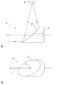
- FIG. 1 is a diagram showing a configuration of an optical system of the moisture detection device 1.
- the moisture detection device 1 includes a light source unit 10, a projection optical system 20, a light receiving optical system 30, and a photodetector 40.
- the light source unit 10 emits a plurality of illumination lights L1 having different wavelengths.
- the projection optical system 20 projects the illumination light L1 emitted from the light source unit 10 onto the road surface.
- the photodetector 40 receives the reflected light R1 of the illumination light L1 reflected on the road surface.
- the light source unit 10 includes three light sources 11, 12, and 13 having different wavelengths from each other.
- the light sources 11, 12, and 13 are laser light sources such as a semiconductor laser, for example.
- the light sources 11, 12, and 13 may be composed of an LED or a white light source with a filter that passes through a specific wavelength.
- the light source 11 emits near-infrared light having a wavelength of 980 nm (hereinafter, referred to as “reference wavelength”).
- the light source 12 emits near-infrared light having a wavelength of 1450 nm (hereinafter, referred to as “absorption wavelength 1”).
- the light source 13 emits near-infrared light having a wavelength of 1550 nm (hereinafter, referred to as “absorption wavelength 2”).
- the light sources 12 and 13 emit the illumination light L1 in the same direction, and the light source 11 emits the illumination light L1 in the direction orthogonal to the emission direction of the light sources 12 and 13.
- the emission optical axes of the light sources 11, 12, and 13 are included in the same plane. That is, the emission optical axes of the light source 11 and the emission optical axes of the light sources 12 and 13 are orthogonal to each other.
- the projection optical system 20 includes collimator lenses 21, 22, 23, a dichroic mirror 24, and a polarization beam splitter (hereinafter referred to as “PBS”) 25.
- the collimator lenses 21, 22, and 23 convert the illumination light L1 emitted from the light sources 11, 12, and 13, respectively, into parallel light.
- the dichroic mirror 24 transmits the illumination light L1 emitted from the light source 11 and reflects the illumination light L1 emitted from the light source 12. As a result, the emission light axis of the light source 11 and the emission light axis of the light source 12 are aligned.
- the PBS 25 transmits the two illumination lights L1 incident from the dichroic mirror 24 side and reflects the illumination light L1 emitted from the light source 13. That is, the light sources 11 and 12 are arranged so that the polarization direction is P-polarized with respect to PBS 25, and the light source 13 is arranged so that the polarization direction is S-polarized with respect to PBS 25. As a result, the emission optical axes of the light sources 11, 12, and 13 are aligned with the optical axis A1 of the projection optical system 20.
- the dichroic mirror 24 and the PBS 25 form a matching optical system 20a that aligns the emission optical axes of the light sources 11, 12, and 13 with each other.
- the light receiving optical system 30 includes an optical element 31.
- the optical element 31 aligns the optical axis A1 of the projection optical system 20 and the optical axis A2 of the light receiving optical system 30 with each other in a road surface side range (range from the optical element 31 to the projection direction of the illumination light L1). That is, these two optical axes A1 and A2 are integrated into the common optical axis A10 by the optical element 31.
- the optical element 31 has a reflecting surface 31a on a surface opposite to the projection optical system 20.
- the reflecting surface 31a is a paraboloid recessed inward of the optical element 31.
- the reflecting surface 31a collects the reflected light R1 incident along the optical axis A10 on the light receiving surface of the photodetector 40.
- the optical axis of the reflecting surface 31a is the optical axis A2 of the light receiving optical system 30.
- the optical axis A2 is perpendicular to the optical axis A1 of the projection optical system 20.
- the optical axis A1 and the optical axis A2 do not have to be perpendicular to each other, and may have other angles.
- the shape of the reflecting surface 31a is changed according to the angle between the optical axis A1 and the optical axis A2, and the arrangement of the photodetector 40 is adjusted so that the light receiving surface is perpendicular to the optical axis A2. ..
- 2 (a) and 2 (b) are a perspective view and a side view showing the configuration of the optical element 31.
- the optical element 31 has a shape in which the upper surface of the columnar member is cut out diagonally.
- the optical element 31 is formed with an opening 31b for passing the illumination light L1 projected from the projection optical system 20.
- the opening 31b is formed by a through hole that penetrates the optical element 31 along the central axis of the optical element 31.
- a slit-shaped notch extending from the outer surface of the optical element 31 to the central axis may be formed to provide the opening 31b.
- the illumination light L1 passes through the opening 31b and is projected onto the road surface.
- the reflected light R1 from the road surface is focused on the photodetector 40 by the reflecting surface 31a.
- the photodetector 40 is composed of, for example, a photodiode.
- a photodiode having a detection sensitivity in an infrared wavelength band for example, 900 to 1800 nm
- the light detector 40 transmits the reference wavelength, the absorption wavelength 1 and the absorption wavelength 2, which are the emission wavelengths of the light sources 11, 12, and 13, and blocks the visible light wavelength band.
- the filter to be used may be arranged in front of the light detector 40.
- the photodetector 40 may be composed of an avalanche photodiode.
- the photodetector 40 receives the reflected light R1 reflected on the road surface by the illumination light L1 emitted from the light sources 11, 12, and 13, and outputs an electric signal based on the received light amount.
- the light sources 11, 12, and 13 are driven so as to emit pulses in a time-division manner. Therefore, the photodetector 40 receives the reflected light R1 based on the illumination light L1 from the light sources 11, 12, and 13 in a time-divided manner, and outputs an electric signal corresponding to the received light amount of each reflected light R1.
- the type of deposits (moisture state) on the road surface is determined. The sediment determination process will be described later with reference to FIG.
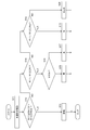
- FIG. 3 is a block diagram showing a configuration of a circuit unit of the moisture detection device 1.
- the moisture detection device 1 includes a control unit 110, a storage unit 120, an output unit 130, and three drive units 141, 142, and 143. , And a processing unit 150.
- the control unit 110 is composed of, for example, a CPU or a microcomputer.
- the control unit 110 controls each unit in the moisture detection device 1 according to the control program stored in the storage unit 120.
- the determination unit 111 is provided in the control unit 110.
- the determination unit 111 determines the type of deposit (water, snow, ice) on the road surface based on the detection signal from the photodetector 40.
- the determination unit 111 may be configured as hardware instead of a function by the control program.
- the storage unit 120 includes a memory, stores a control program, and is used as a work area during control processing.
- the output unit 130 outputs the determination result of the determination unit 111.
- the output unit 130 may be a display unit such as a monitor arranged in the moisture detection device 1, or may be a communication module for transmitting the determination result of the determination unit 111 to an external processing device such as a server. Good.
- the drive units 141, 142, and 143 drive the light sources 11, 12, and 13, respectively, according to the control from the control unit 110.
- the processing unit 150 converts the electric signal input from the photodetector 40 into a digital signal, takes a logarithm, and outputs the logarithm to the control unit 110.
- the control unit 110 determines the type (moisture state) of the road surface deposits based on the detection signal input from the processing unit 150. This determination is performed by the determination unit 111 as described above.
- FIG. 4 is a graph showing the light absorption coefficient in water and ice.
- the reference wavelength, the absorption wavelength 1 and the absorption wavelength 2 set for the emission wavelengths of the light sources 11, 12 and 13, respectively, are indicated by arrows.
- the absorption coefficient of the reference wavelength for water and ice is smaller than the absorption coefficient of the absorption wavelength 1 and the absorption wavelength 2. That is, the illumination light L1 having the reference wavelength is absorbed less by water or ice than the illumination light L1 having the absorption wavelength 1 and the absorption wavelength 2. Therefore, the illumination light L1 (reference wavelength) emitted from the light source 11 is likely to be reflected by the road surface even if moisture (water, ice, snow) is present in the irradiation region on the road surface, and the illumination light L1 (reference wavelength). The amount of received light is increased by the light detector 40 with respect to the reflected light R1 of (wavelength).
- the absorption wavelengths 1 and 2 emitted from the light sources 12 and 13 have a large absorption coefficient due to water or ice. Therefore, when there is moisture in the irradiation region, the illumination light L1 having absorption wavelengths 1 and 2 is absorbed by the moisture, and the amount of reflected light R1 having absorption wavelengths 1 and 2 received by the photodetector 40 is reduced.
- water and ice are discriminated by using the difference between the absorption coefficients of the absorption wavelength 1 and the absorption wavelength 2. That is, at the absorption wavelength 1 (1450 nm), the absorption coefficient in water is larger than the absorption coefficient in ice, and at the absorption wavelength 2 (1550 nm), the absorption coefficient in ice is larger than the absorption coefficient in water. Therefore, by taking the ratio of the detection signals of the absorption wavelength 1 and the absorption wavelength 2, when there is water at the irradiation position, it can be determined whether it is water or ice.
- FIG. 5 is a flowchart showing a process of determining the type of deposit by the control unit 110 (determination unit 111).
- the control unit 110 drives the light source unit 10 (S11). Specifically, the control unit 110 emits the illumination light L1 from the light sources 11, 12, and 13 in a time-division manner via the drive units 141, 142, and 143. Then, the control unit 110 uses the detection signal output from the photodetector 40 in response to the drive of the light source 11, the detection signal output from the photodetector 40 in response to the drive of the light source 12, and the drive of the light source 13. Correspondingly, the detection signal output from the photodetector 40 is acquired via the processing unit 150.
- the determination unit 111 of the control unit 110 determines the state of the irradiation position based on the intensity of the detection signal of the reference wavelength, the intensity of the detection signal of the absorption wavelength 1, and the intensity of the detection signal of the absorption wavelength 2.
- the value R11 obtained by logarithmically converting the ratio of the intensity of the detection signal of the absorption wavelength 1 to the intensity of the detection signal of the reference wavelength is the threshold value Rth1 or more, and the intensity of the detection signal of the reference wavelength is
- the value R12 obtained by logarithmically converting the ratio of the intensity of the detection signal of the absorption wavelength 2 to the threshold value Rth2 or more (S12: YES)
- the threshold Rth1 is the thickness obtained by subtracting the value of the absorption coefficient of the absorption wavelength 1 (1450 nm) for water from the value of the absorption coefficient of the reference wavelength (980 nm) for water, and determining that there is water in that value. It is a value multiplied by twice. For example, when detecting water having a thickness of 10 ⁇ m or more, the value of Rth1 is ⁇ 0.062.
- the threshold Rth2 is the thickness obtained by subtracting the value of the absorption coefficient of the absorption wavelength 2 (1550 nm) for ice from the value of the absorption coefficient of the reference wavelength (980 nm) for ice, and determining that there is ice in that value. It is the value multiplied by twice. For example, when detecting ice having a thickness of 10 ⁇ m or more, the value of Rth2 is ⁇ 0.069.
- step S12 determines that moisture is present at the irradiation position, and proceeds to the process in step S14.
- the determination unit 111 calculates the ratio of the value R11 and the value R12, and determines whether or not the value is equal to or less than the threshold value Ri.
- the value of the threshold Ri is a value obtained by subtracting the absorption coefficient of the reference wavelength (980 nm) from the absorption coefficient of the absorption wavelength 1 (1450 nm) in ice and the reference wavelength (1550 nm) from the absorption coefficient of the absorption wavelength 2 (1550 nm) in ice. It is a ratio of values obtained by subtracting the absorption coefficient of 980 nm).
- the determination unit 111 determines that only ice or snow exists at the irradiation position, and proceeds to step S15.
- the ratio of the value R11 to the value R12 exceeds the threshold value Ri (S14: NO)
- the determination unit 111 determines that water or water and ice are present at the irradiation position, and proceeds to step 18.
- step S15 the determination unit 111 determines whether or not the light receiving intensity Ir of the reference wavelength is equal to or greater than the threshold value Is.
- the determination unit 111 determines that snow exists at the irradiation position (S16).
- the determination unit 111 determines that ice is present at the irradiation position (S17).
- the control unit 110 may measure the thickness thereof from the values of the detection signals of the reference wavelength and the absorption wavelength 1.
- step S18 the determination unit 111 calculates the ratio of the value R11 and the value R12, and determines whether or not the value is equal to or greater than the threshold value Rw.
- the determination unit 111 determines that water is present at the irradiation position (S19).
- the control unit 110 may further measure the thickness of water from the values of the detection signals of the reference wavelength and the absorption wavelength 2.
- the determination unit 111 has a mixture of water and ice at the irradiation position.
- the control unit 110 calculates the ratio of water and ice existing at the irradiation position by comparing the value of (R11 / R12-Ri) and the value of (Rw-R11 / R12), and the ratio and the ratio.
- the film thickness of the mixture of water and ice may be measured from the values of the detection signals of the reference wavelength, the absorption wavelength 1 and the absorption wavelength 2.
- the illumination light L1 with the reference wavelength is used. It is preferable that as much light as possible of the reflected light R1 is received by the light detector 40.
- the reflectance of the illumination light L1 with respect to the road surface changes depending on the polarization direction of the illumination light L1 with respect to the road surface.
- FIG. 6A is a diagram schematically showing an example of the installation state of the moisture detection device 1
- FIG. 6B is a graph showing the relationship between the incident angle of light with respect to the water surface and the reflectance.
- the photodetector 40 is not shown in FIG. 6A.
- the moisture detection device 1 is installed so that the illumination light L1 is incident on the road surface in an oblique direction.
- the moisture detection device 1 is installed in a state of being tilted with respect to the road surface RS1 as shown in FIG. 6A.
- the illumination light L1 is specularly reflected by the road surface RS1 or its deposits.
- the specularly reflected reflected light R2 does not enter the reflecting surface 31a of the optical element 31, and therefore the reflected light R2 is not received by the light detector 40.
- the reflected light R1 reflected in the direction of backliting the light path of the illumination light L1 enters the reflecting surface 31a of the optical element 31 and is focused on the photodetector 40.
- the reflectance differs depending on the polarization direction of the light with respect to the road surface RS1.
- the higher the reflectance the greater the amount of light lost due to specular reflection, so that the amount of reflected light R1 received by the photodetector 40 decreases.
- the reflectance of S-polarized light becomes larger than the reflectance of P-polarized light at substantially all incident angles. Therefore, when the illumination light L1 is incident with S-polarized light, the light receiving efficiency with respect to the emitted power becomes worse.
- the illumination light L1 of the reference wavelength is incident on the road surface RS1 with P-polarized light.
- the arrangement of the light sources 11, 12, and 13 is set. Specifically, in the configuration of FIG. 6A, the light source 11 that emits the illumination light L1 is arranged so that the illumination light L1 having the reference wavelength having the lowest detection sensitivity is P-polarized with respect to the road surface RS1. Just do it. As a result, it is possible to suppress a decrease in the light receiving efficiency of the reflected light R1 having a reference wavelength with respect to the photodetector 40.
- the illumination light L1 having the absorption wavelength 1 having the second lowest detection sensitivity in the photodetector 40 is also incident on the road surface RS1 with P-polarized light.
- the light source 12 that emits the illumination light L1 may be arranged so that the illumination light L1 having the absorption wavelength 1 is P-polarized with respect to the road surface RS1. As a result, it is possible to suppress a decrease in the light receiving efficiency of the reflected light R1 having the absorption wavelength 1 with respect to the photodetector 40.
- the polarization directions of the illumination lights L1 emitted from the light sources 11 and 12 are the same, so that the illumination lights L1 can be incident on the PBS 25 with P-polarized light. it can.
- the illumination light L1 emitted from each of the light sources 11 and 12 can be configured to pass through the PBS 25.
- the light receiving efficiency of the reflected light R1 of the illumination light L1 with respect to the light detector 40 is different. It is lower than that of the two illumination lights L1.
- the detection sensitivity of the absorption wavelength 2 in the light detector 40 is higher than that of the reference wavelength and the absorption wavelength 1 as described above, the illumination light L1 having the absorption wavelength 2 emitted from the light source 13 is described. Even if the light receiving efficiency is lowered, the detection signal based on the reflected light R1 having the absorption wavelength 2 does not become extremely small.
- FIG. 6A shows a case where the light detector 40 has the lowest detection sensitivity with respect to the reference wavelength and the light detector 40 has the highest detection sensitivity with respect to the absorption wavelength 2 among the reference wavelengths 1 and 2.
- the arrangement positions of the light sources 11, 12, and 13 of the above are shown, but when the detection sensitivity of the light detector 40 for each wavelength is different from this, the illumination of the wavelength having the lowest detection sensitivity and the wavelength having the second lowest detection sensitivity.
- the arrangement of the light sources 11, 12, and 13 may be adjusted so that the light L1 is P-polarized with respect to the road surface RS1 and the illumination light L1 having the remaining wavelength is S-polarized with respect to the road surface RS1.
- the illumination light L1 having the lowest detection sensitivity of the photodetector 40 may be set to P-polarized light with respect to the road surface RS1, and any of the illumination lights L1 having the remaining two wavelengths may be set with respect to the road surface RS1. Whether to set to P polarization may be arbitrarily selected.
- the detection sensitivity of the light detector 40 is the lowest reference.
- Light sources 11 and 12 so that the illumination light L1 of the wavelength (emission light of the light source 11) is transmitted through the dichroic mirror 24 and the illumination light L1 of the absorption wavelength 1 (emission light of the light source 12) is reflected by the dichroic mirror 24. It is preferable to be arranged. This makes it possible to prevent the amount of received light received by the reflected light R1 having the reference wavelength from decreasing. Therefore, it is possible to prevent the detection signal of the reflected light R1 having the reference wavelength having the lowest detection sensitivity from becoming extremely small.
- the emission powers of the light sources 11, 12, and 13 must meet the safety standards for laser light.
- FIG. 7 is a graph showing the relationship between the pulse width and the peak power satisfying the condition that the laser safety standard is class 1 when the wavelength is 980 nm, the repetition frequency is 1 kHz, and the viewing angle is 1.5 mrad.
- the pulse width of the illumination light L1 emitted from the light sources 11, 12, and 13 of the moisture detection device 1 is limited by the response frequency of the photodetector 40.
- illumination light L1 reference wavelength: 980 nm
- the allowable peak power is in the region W1 having a pulse width of 2.6 ⁇ sec or more and less than 5 ⁇ sec. , It is smaller than the peak power when the pulse width is 5 ⁇ sec.
- JIS C68002_002 states that the peak power allowed in a certain pulse width is also allowed in a smaller pulse width. According to this, for example, when the pulse width is 3 ⁇ sec, by using the peak power allowed in 5 ⁇ sec, the energy consumption can be reduced as compared with the case where the pulse width is set to 5 ⁇ sec. Similarly, in the region W1 having a pulse width of 2.6 ⁇ sec or more and less than 5 ⁇ sec, by using the peak power allowed at 5 ⁇ sec, energy consumption can be reduced as compared with the case where the pulse width is set to 5 ⁇ sec.
- the peak allowed in the actual pulse width is used by using the peak power allowed when the pulse width is 5 ⁇ sec in such a region where the pulse width is smaller than 5 ⁇ sec.
- the frequency band in which a power larger than the power can be used is approximately 60 Hz to 14 kHz.
- a region in which a larger power can be used by using a peak power that is allowed with a pulse width larger than the actual pulse width Does not exist in the pulse width range of 10 ⁇ (-3) ⁇ sec to 10 ⁇ (-10) ⁇ sec.
- FIG. 8 is a diagram schematically showing the configuration of the road surface information distribution system 200.
- the road surface information distribution system 200 includes a moisture detection device 1 and a management server 2.
- the road 3 continues to the inside of the tunnel 5 through the bridge 4 and the exit 5a of the tunnel 5.
- the moisture detection device 1 is installed on the side of the road 3 via a pole or the like, and is also installed on an outdoor light or a wall surface installed on the side of the road 3.
- the moisture detection device 1 detects the state of the road surface 3a of the road 3.
- FIG. 8 shows two moisture detection devices 1, and the moisture detection device 1 on the front side detects the state of the region 3a1 of the road surface 3a located on the bridge 4, and the moisture detection device 1 on the back side. Detects the state of the region 3a2 of the road surface 3a located near the exit 5a of the tunnel 5.
- the moisture detection device 1 determines the moisture state (sediment type, thickness, etc.) of each detection target region of the road surface 3a, and transmits the determination result to the management server 2 via the base station 6 and the network network 7. .
- the base station 6 is installed so as to include the moisture detection device 1 within a communicable range, and is configured to be able to communicate with the moisture detection device 1 wirelessly.
- the output unit 130 of FIG. 3 is composed of a communication module.
- the base station 6 is connected to the network network 7.
- the network network 7 is, for example, the Internet.
- the management server 2 is installed in the road surface condition distribution center 8 or the like and is connected to the network network 7.
- the management server 2 generates map information for notifying the state of the road surface 3a based on the information about the road surface condition delivered by the moisture detection device 1, and uses the generated map information for the network network 7 and the base station 6. Delivered to vehicles, etc. via.
- the distributed map information is displayed on the display unit of the car navigation system mounted on the vehicle. The driver can check the displayed contents and grasp the state of the road surface 3a of the traveling route. Thereby, the safety when traveling on the road surface 3a can be enhanced.
- the moisture detection device 1 may be mounted on the vehicle.
- the moisture detection device 1 is installed in the vehicle so that the illumination light L1 irradiates the road surface directly under the vehicle.
- the moisture detection device 1 detects the road surface condition directly under the vehicle and displays the detection result on the vehicle navigation system.
- the detection of the road surface condition is also performed when the vehicle is running and is displayed on the navigation system at any time. As a result, the driver can accurately grasp the condition of the road surface currently being driven.
- the road surface detection result by the moisture detection device 1 may be further transmitted from the navigation system to the management server 2 of FIG. 8 together with the information indicating the current traveling position, and aggregated in the management server 2.
- the management server 2 can generate finer map information indicating the state of the road based on the detection result of the road surface aggregated from each vehicle. The driver can more accurately grasp the condition of the road that can be a driving route.
- the optical axis A1 of the projection optical system 20 and the optical axis A2 of the light receiving optical system 30 are aligned with each other in the range of the road surface side (object side), they are reflected by the road surface (object).
- the reflected light R1 that reverses the matched optical axis A10 can be focused on the photodetector 40 by the light receiving optical system 30. Therefore, it is not necessary to adjust the angle between the illumination light L1 and the reflected light R1 with respect to the road surface according to the distance between the moisture detection device 1 and the road surface, and the reflected light R1 from the road surface is detected without such adjustment. It is possible to detect the state of water content (water, ice, snow) in the object by appropriately receiving light with the device 40.
- the adjustment work at the time of installation can be simplified, and the moisture detection device 1 can be easily installed. Further, when the moisture detection device 1 is installed in the vehicle, the state of the road surface can be detected without any problem even if the distance to the road surface changes from moment to moment. Therefore, the moisture detection device 1 can be installed on a moving body such as a vehicle.
- the optical element 31 has an opening 31b that allows the illumination light L1 to pass through and leads to the road surface, and an opening 31b that is formed around the opening 31b and reflects the reflected light R1. It is provided with a reflecting surface 31a that leads to the detector 40. As a result, the optical axes of the illumination light L1 and the reflected light R1 can be aligned while suppressing a decrease in the utilization efficiency of the reflected light R1.
- the reflecting surface 31a is a paraboloid that condenses the reflected light R1 on the photodetector 40, and is included in the components of the light receiving optical system 30.
- a condensing lens or the like for condensing the reflected light R1 on the photodetector 40, and the configuration of the moisture detection device 1 can be simplified and the cost can be reduced.
- the light source unit 10 includes a plurality of light sources 11, 12, and 13 that emit light having different wavelengths from each other, and the projection optical system 20 has emission optical axes of the light sources 11, 12, and 13.
- a matching optical system 20a for matching with each other is provided.
- the matching optical system 20a includes a dichroic mirror 24 that aligns the emission optical axes of the light source 11 and the light source 12. As a result, the emission optical axes of the light sources 11 and 12 having significantly different emission wavelengths can be easily aligned.
- the reference in the dichroic mirror 24 it is preferable to arrange the light sources 11 and 12 with respect to the dichroic mirror 24 so that the loss of light having a wavelength is smaller than the loss of light having an absorption wavelength of 1.
- the illumination light L1 having the reference wavelength it is possible to prevent the illumination light L1 having the reference wavelength from being attenuated by the dichroic mirror 24, and it is possible to secure the amount of received light of the reflected light R1 having the reference wavelength in the photodetector 40. Therefore, it is possible to prevent the detection signal of the reflected light R1 having the reference wavelength having the lowest detection sensitivity from becoming extremely small.
- the matching optical system 20a includes PBS 25 for aligning the emission light axis of the light source 13 with the emission light axes of the light source 11 and the light source 12, and illumination light having a reference wavelength, an absorption wavelength 1 and an absorption wavelength 2.
- the polarization directions of the light sources 11, 12, and 13 are set so that at least the illumination light L1 having the reference wavelength having the lowest detection sensitivity in the light detector 40 is P-polarized with respect to the road surface (object). ing.
- FIGS. 6A and 6B it is possible to suppress a decrease in the light receiving efficiency of the reflected light R1 having the reference wavelength in the photodetector 40. Therefore, it is possible to prevent the detection signal of the reflected light R1 having a reference wavelength having a low detection sensitivity from becoming extremely small, and it is possible to accurately determine the type of deposit and the thickness of the deposit shown in FIG. It can be carried out.
- the determination unit 111 standardizes the detection signals for the two detection illumination lights L1 having the absorption wavelengths 1 and 2 with the detection signals for the reference illumination light L1 having the reference wavelength R11. , R12 to determine deposits (snow, ice, water) on the road surface.
- the detection signal for the illumination light L1 with the absorption wavelengths 1 and 2 by standardizing the detection signal for the illumination light L1 with the absorption wavelengths 1 and 2 by the detection signal for the illumination light L1 with the reference wavelength that is not so affected by moisture, noise components such as scattering due to the shape of the road surface are standardized. Can be suppressed. Therefore, the state of water on the road surface (type of deposit) can be accurately determined.
- FIG. 9 is a diagram showing the configuration of the optical system of the moisture detection device 1 according to the modification example 1.
- the reflecting surface 31c of the optical element 31 is changed to a flat surface, and the condensing lens 32 for condensing the reflected light R1 on the photodetector 40 is a light receiving optical system. It has been added as 30 components.
- the condenser lens 32 for example, a spherical lens can be used.
- the optical axis A10 aligns the optical axis A1 of the projection optical system 20 with the optical axis A2 of the light receiving optical system 30 by the optical element 31. Therefore, as in the above embodiment, it is not necessary to adjust the angles of the illumination light L1 and the reflected light R1 with respect to the road surface according to the distance between the moisture detection device 1 and the road surface, and even if such adjustment is not performed, the angle from the road surface can be adjusted.
- the reflected light R1 can be appropriately received by the photodetector 40.
- 10 (a) and 10 (b) show the reflected light R1 when the reflected light R1 is condensed by the light detector 40 by the condensing lens 32 (modification example 1) and the reflecting surface 31a (embodiment), respectively. It is a figure which shows the simulation result which obtained the condensing state by the simulation.
- infrared light (reflected light R1) of 980 nm, 1450 nm, and 1550 nm emitted from a point light source 10 m away is used as a spherical lens (condensing lens 32) having a diameter of 50 mm and a focal length of 100 mm and a parabolic mirror (condensing lens 32).
- the verification condition was to collect light on a 1 mm light receiving surface using the reflecting surface 31a).
- the reflected light R1 of the illumination light L1 having the reference wavelength (980 nm), the absorption wavelength 1 (1450 nm) and the absorption wavelength 2 (1550 nm) is shown in the condenser lens 32 and the radial surface.
- the distribution of infrared light of each wavelength on the light receiving surface of the light detector 40 when the light is focused on the reflecting surface 31a of the shape is shown.
- the reflected light R1 when the reflected light R1 is condensed by using a spherical lens (condensing lens 32), the reflected light rays are spread over the entire light receiving surface, and the rays of the reflected light are spread for each wavelength.
- the focusing position is different.
- the reflected light R1 when the reflected light R1 is condensed by using the parabolic mirror (reflecting surface 31a), the reflected light R1 is collected in a narrow area as compared with the case where the spherical lens (condensing lens 32) is used. It can be seen that the light is shining and that the light rays of the reflected light R1 of all wavelengths pass through the same position.
- the photodetector 40 having a smaller size can be used as compared with the configuration of the modified example 1 shown in FIG. 9, and the detection accuracy of the reflected light R1 of each wavelength is improved. be able to.
- the optical element 31 having the reflecting surface 31a and the opening 31b is used to align the optical axis A1 of the projection optical system 20 with the optical axis A2 of the light receiving optical system 30.
- the optical axis A1 of the projection optical system 20 and the optical axis A2 of the light receiving optical system 30 are aligned by using a small mirror.
- FIG. 11 is a diagram showing a configuration of an optical system of the moisture detection device 1 according to the second modification.
- the optical element 31 is omitted and the optical element 26 is added as a component of the projection optical system 20 as compared with the configuration of FIG.
- the condenser lens 32 is added as a component of the light receiving optical system 30 as in the configuration of FIG.
- Other configurations are the same as in FIG.
- the optical element 26 is a flat mirror.
- the reflecting surface 26a of the optical element 26 is slightly larger than the beam size of the illumination light L1 collimated by the collimator lenses 21, 22, and 23.
- the shape of the optical element 26 is a shape corresponding to the beam shape of the illumination light L1 incident on the optical element 26.
- the optical element 26 reflects the illumination light L1 and guides the reflected light R1 passing around the optical element 26 to the photodetector 40.
- the optical element 26 bends the optical axis A1 of the projection optical system 20 in a direction parallel to the optical axis A2 of the light receiving optical system 30 to align the optical axes A1 and A2.
- the optical element 26 is arranged at a position where the optical axis A1 of the projection optical system 20 and the optical axis A2 of the light receiving optical system 30 intersect.
- the optical element 26 can align the optical axis A1 of the projection optical system 20 and the optical axis A2 of the light receiving optical system 30 with the common optical axis A10. Therefore, as in the above embodiment, it is not necessary to adjust the angles of the illumination light L1 and the reflected light R1 with respect to the road surface according to the distance between the moisture detection device 1 and the road surface, and even if such adjustment is not performed, the angle from the road surface can be adjusted.
- the reflected light R1 can be appropriately received by the photodetector 40.
- the reflected light R1 is condensed by the condensing lens 32 on the light detector 40 as in the configuration of FIG. 9, and therefore, it has been described with reference to FIGS. 10 (a) and 10 (b).
- the reflected light R1 is affected by the spherical aberration and the chromatic aberration caused by the condenser lens 32. This effect is eliminated by using a parabolic mirror instead of the condenser lens 32.
- FIG. 12 is a diagram showing the configuration of the optical system of the moisture detection device 1 when the condenser lens 32 is replaced with the parabolic mirror 33 in the configuration of FIG.
- the parabolic surface mirror 33 has a parabolic surface-shaped reflecting surface 33a.
- the reflecting surface 33a has a shape similar to the shape in which the opening 31b is omitted from the reflecting surface 31a shown in FIGS. 2A and 2B.
- the reflecting surface 33a vertically bends the optical axis A2 of the light receiving optical system 30 and concentrates the reflected light R1 on the light receiving surface of the photodetector 40.
- the bending angle of the optical axis A2 is not limited to 90 degrees, and may be another angle. In this configuration, the parabolic mirror 33 is included in the components of the light receiving optical system 30.
- the photodetector 40 having a smaller size than the configuration of FIG. 11 can be used, and the detection accuracy of the reflected light R1 of each wavelength can be improved.
- the matching optical system 20a is composed of a dichroic mirror 24 and a PBS 25.
- the dichroic mirror 27 is used instead of the PBS 25.
- FIG. 13 is a diagram showing a configuration of an optical system of the moisture detection device 1 according to the third modification.
- the PBS 25 in the configuration of FIG. 1 is replaced with the dichroic mirror 27.
- Other configurations are the same as in FIG.
- the dichroic mirror 27 transmits the illumination light L1 having the reference wavelength and the absorption wavelength 1 emitted from the light sources 11 and 12, respectively, and reflects the illumination light L1 having the absorption wavelength 2 emitted from the light source 13.
- the emission optical axes of the light sources 11, 12, and 13 are aligned.
- the light source that emits the illumination light L1 is arranged so that the illumination light L1 having a wavelength having a low detection sensitivity in the photodetector 40 is P-polarized with respect to the road surface. .. Further, it is preferable that the arrangement of the light sources 11, 12, and 13 is adjusted so that the attenuation of the dichroic mirrors 24 and 27 is suppressed with respect to the illumination light L1 having a wavelength having a low detection sensitivity in the photodetector 40.
- the configuration of FIG. 13 is a case where high transmission efficiency and reflection efficiency of the dichroic mirror 27 with respect to absorption wavelengths 1 and 2 can be ensured even when the wavelength difference between the absorption wavelengths 1 and 2 is the wavelength difference shown in FIG. , Can be applied.
- the absorption wavelengths 1 and 2 may be set so that the wavelength difference becomes larger than the establishment method shown in FIG. 4 within the range where the determination shown in FIG. 5 is possible. As a result, high transmission efficiency and reflection efficiency of the dichroic mirror 27 with respect to absorption wavelengths 1 and 2 can be ensured.
- the types of wavelengths used as the illumination light L1 are not limited to three.
- the type of deposit may be determined using two light sources that emit illumination light L1 having a reference wavelength and illumination light L1 having an absorption wavelength, and a radiation temperature sensor that detects the temperature of the road surface. In this case, either the dichroic mirror 24 or the PBS 25 is omitted from the matching optical system 20a.
- the presence or absence of snow on the road surface is determined by comparing the light receiving intensity Ir of the reflected light R1 having the reference wavelength with the threshold number Is, but the illumination light L1 projected from the projection optical system 20 is used. Even if the thickness of snow is further measured using a TOF (Time Of Flight) sensor that measures the distance to the object based on the time it takes for the object to be reflected and received by the photodetector 40. Good. By using the TOF sensor, the thickness of snow can be measured accurately.
- TOF Time Of Flight
- the light having a reference wavelength emitted from the light source 11 is near-infrared light having a wavelength of 980 nm, but the reference wavelength is not limited to 980 nm and is another wavelength that is less absorbed by water. May be good.
- the light having a reference wavelength is not limited to near-infrared light, and may be visible light having a wavelength of 750 nm or less. However, if the light having the reference wavelength is visible light, the road surface 3a may be illuminated and the traffic on the road 3 may be hindered. Therefore, the light having the reference wavelength is preferably near infrared light.
- the shape and size of the optical components constituting the optical system are not limited to those shown in the above-described embodiment and modification examples 1 to 3, and can be appropriately changed.
- the optical element 31 shown in FIG. 1 may have a plate shape
- the parabolic mirror 33 shown in FIG. 12 may have a plate shape.
- the type of deposit on the road surface is determined, but the determination target is not limited to this, and the thickness, slipperiness, etc. of the deposit may be further determined. ..
- the state of water (water, ice, snow) on the road surface is detected, but the object for detecting the state of water is not necessarily limited to the road surface.
- the present invention may be applied to a moisture detection device that detects the state of moisture on the surface of a floor or desk, or a moisture detection device that detects moisture in leaves.
- the number and type of light used for detection may be adjusted according to the type of moisture to be detected and the like.
- the application example of the moisture detection device 1 is not limited to the road surface information distribution system 200 shown in FIG. 8 and the application example in which the moisture detection device 1 is mounted on the vehicle, and the illumination light and the reflected light are used. As long as the configuration is such that the state of moisture of the object is detected, the moisture detection device 1 may be used for other configurations.
- Moisture detector 10 Light source 11, 12, 13 Light source 20 Projection optical system 20a Matching optical system 24, 27 Dichroic mirror 25 Polarized beam splitter 26 Optical element (mirror) 30 Light receiving optical system 31 Optical element 31a Reflective surface 31b Aperture 40 Photodetector 111 Judgment unit
Abstract
Provided is a moisture sensing device (1) comprising: a light source unit (10); a projection optical assembly (20) which projects illumination light (L1) emitted from the light source unit (10) on a road surface; a photodetector (40) which receives reflected light (R1) of the illumination light (L1) reflected from the road surface; and a light receiving optical assembly (30) which focuses the reflected light (R1) on the photodetector (40). Said device further comprises an optical element (31) for mutually aligning the optical axis (A1) of the projection optical assembly (20) and optical axis (A2) of the light receiving optical assembly (30) in the road surface-side range.
Description
本発明は、対象物における水分の状態を検知する水分検知装置に関し、たとえば、路面上に堆積した水、氷および雪等の状態を検知する場合に用いて好適なものである。
The present invention relates to a moisture detection device that detects the state of moisture in an object, and is suitable for use, for example, when detecting the state of water, ice, snow, etc. deposited on the road surface.
従来、路面の状態を検知する路面検知装置が知られている。たとえば、以下の特許文献1には、路面の被検知領域に照明光を照射し、その反射光に基づいて、氷や水等の被検出物が被検知領域に存在するか否かを判定する路面状態検知装置が記載されている。この装置では、照明光として、互いに波長の異なる検出光と参照光が順次切り替えられて被検知領域に照射される。また、各光の切り替えに同期して、各光の反射光が受光され電気信号が生成される。そして、これら電気信号が比較演算され、その演算結果に基づいて、水や氷等の被検知物が被検知領域に存在するか否かが判定される。
Conventionally, a road surface detection device that detects the condition of the road surface is known. For example, in Patent Document 1 below, an illumination light is applied to a detected area on a road surface, and based on the reflected light, it is determined whether or not an object to be detected such as ice or water exists in the detected area. A road surface condition detection device is described. In this device, the detection light and the reference light having different wavelengths are sequentially switched as the illumination light to irradiate the detected region. Further, in synchronization with the switching of each light, the reflected light of each light is received and an electric signal is generated. Then, these electric signals are compared and calculated, and based on the calculation result, it is determined whether or not an object to be detected such as water or ice exists in the detected region.
上記特許文献1の構成では、照明光と反射光が、それぞれ、別々の光学系により、互いに異なる方向において、個別に照射および受光される。このため、路面状態検知装置と検知領域との距離に応じて、照明光の照射角度と反射光の受光角度を調整する必要がある。このような調整作業は、極めて繁雑である。
In the configuration of Patent Document 1, the illumination light and the reflected light are individually irradiated and received by different optical systems in different directions. Therefore, it is necessary to adjust the irradiation angle of the illumination light and the reception angle of the reflected light according to the distance between the road surface condition detection device and the detection area. Such adjustment work is extremely complicated.
かかる課題に鑑み、本発明は、煩雑な調整作業を行うことなく対象物における水分の状態を検知することが可能な水分検知装置を提供することを目的とする。
In view of such a problem, an object of the present invention is to provide a moisture detection device capable of detecting the state of moisture in an object without performing complicated adjustment work.
本発明の主たる態様に係る水分検知装置は、光源部と、前記光源部から出射された照明光を対象物に投射する投射光学系と、前記対象物で反射された前記照明光の反射光を受光する光検出器と、前記反射光を前記光検出器に集光させる受光光学系と、前記投射光学系の光軸と前記受光光学系の光軸とを前記対象物側の範囲において互いに整合させる光学素子と、を備える。
The moisture detection device according to the main aspect of the present invention has a light source unit, a projection optical system that projects illumination light emitted from the light source unit onto an object, and reflected light of the illumination light reflected by the object. The light detector that receives light, the light receiving optical system that collects the reflected light on the light detector, and the optical axis of the projection optical system and the optical axis of the light receiving optical system are aligned with each other in the range on the object side. It is provided with an optical element to be operated.
本態様に係る水分検知装置によれば、投射光学系の光軸と前記受光光学系の光軸とが前記対象物側の範囲において互いに整合されるため、対象物で反射された反射光のうち、整合された光軸を逆行する反射光を、受光光学系により光検出器に集光させることができる。よって、装置と対象物との距離に応じて対象物に対する照明光と反射光の角度を調整する必要がなく、このような調整をせずとも、対象物からの反射光を光検出器により適正に受光することができる。
According to the moisture detection device according to this aspect, since the optical axis of the projection optical system and the optical axis of the light receiving optical system are aligned with each other in the range on the object side, among the reflected light reflected by the object. , The reflected light that reverses the aligned optical axis can be focused on the photodetector by the light receiving optical system. Therefore, it is not necessary to adjust the angle between the illumination light and the reflected light with respect to the object according to the distance between the device and the object, and the reflected light from the object is appropriately measured by the photodetector without such adjustment. Can receive light.
以上のとおり、本発明によれば、煩雑な調整作業を行うことなく対象物における水分の状態を検知することが可能な水分検知装置を提供できる。
As described above, according to the present invention, it is possible to provide a moisture detection device capable of detecting the state of moisture in an object without performing complicated adjustment work.
本発明の効果ないし意義は、以下に示す実施形態の説明により更に明らかとなろう。ただし、以下に示す実施形態は、あくまでも、本発明を実施化する際の一つの例示であって、本発明は、以下の実施形態に記載されたものに何ら制限されるものではない。
The effect or significance of the present invention will be further clarified by the description of the embodiments shown below. However, the embodiments shown below are merely examples when the present invention is put into practice, and the present invention is not limited to those described in the following embodiments.
ただし、図面はもっぱら説明のためのものであって、この発明の範囲を限定するものではない。
However, the drawings are for illustration purposes only and do not limit the scope of the present invention.
以下、本発明の実施形態について、図を参照して説明する。本実施形態では、対象物である路面に堆積した水分(水、雪、氷等)を検知する水分検知装置に、本発明が適用されている。
Hereinafter, embodiments of the present invention will be described with reference to the drawings. In the present embodiment, the present invention is applied to a moisture detection device that detects moisture (water, snow, ice, etc.) accumulated on a road surface which is an object.
<光学系の構成>
図1は、水分検知装置1の光学系の構成を示す図である。 <Composition of optical system>
FIG. 1 is a diagram showing a configuration of an optical system of themoisture detection device 1.
図1は、水分検知装置1の光学系の構成を示す図である。 <Composition of optical system>
FIG. 1 is a diagram showing a configuration of an optical system of the
水分検知装置1は、光源部10と、投射光学系20と、受光光学系30と、光検出器40とを備える。光源部10は、波長が互いに異なる複数の照明光L1を出射する。投射光学系20は、光源部10から出射された照明光L1を路面に投射する。光検出器40は、路面で反射された照明光L1の反射光R1を受光する。
The moisture detection device 1 includes a light source unit 10, a projection optical system 20, a light receiving optical system 30, and a photodetector 40. The light source unit 10 emits a plurality of illumination lights L1 having different wavelengths. The projection optical system 20 projects the illumination light L1 emitted from the light source unit 10 onto the road surface. The photodetector 40 receives the reflected light R1 of the illumination light L1 reflected on the road surface.
光源部10は、互いに波長が異なる3つの光源11、12、13を備える。光源11、12、13は、たとえば、半導体レーザ等のレーザ光源である。光源11、12、13が、LEDや、特定波長を通過するフィルタをつけた白色光源により構成されてもよい。光源11は、波長980nm(以下、「参照波長」と称する)の近赤外光を出射する。光源12は、波長1450nm(以下、「吸収波長1」と称する)の近赤外光を出射する。光源13は、波長1550nm(以下、「吸収波長2」と称する)の近赤外光を出射する。
The light source unit 10 includes three light sources 11, 12, and 13 having different wavelengths from each other. The light sources 11, 12, and 13 are laser light sources such as a semiconductor laser, for example. The light sources 11, 12, and 13 may be composed of an LED or a white light source with a filter that passes through a specific wavelength. The light source 11 emits near-infrared light having a wavelength of 980 nm (hereinafter, referred to as “reference wavelength”). The light source 12 emits near-infrared light having a wavelength of 1450 nm (hereinafter, referred to as “absorption wavelength 1”). The light source 13 emits near-infrared light having a wavelength of 1550 nm (hereinafter, referred to as “absorption wavelength 2”).
光源12、13は、同一方向に照明光L1を出射し、光源11は、光源12、13の出射方向に直交する方向に照明光L1を照射する。光源11、12、13の出射光軸は、同一平面に含まれる。すなわち、光源11の出射光軸と、光源12、13の出射光軸とは、互いに直交する。
The light sources 12 and 13 emit the illumination light L1 in the same direction, and the light source 11 emits the illumination light L1 in the direction orthogonal to the emission direction of the light sources 12 and 13. The emission optical axes of the light sources 11, 12, and 13 are included in the same plane. That is, the emission optical axes of the light source 11 and the emission optical axes of the light sources 12 and 13 are orthogonal to each other.
投射光学系20は、コリメータレンズ21、22、23と、ダイクロイックミラー24と、偏光ビームスプリッタ(以下、「PBS」という)25とを備える。コリメータレンズ21、22、23は、それぞれ、光源11、12、13から出射された照明光L1を平行光に変換する。ダイクロイックミラー24は、光源11から出射された照明光L1を透過し、光源12から出射された照明光L1を反射する。これにより、光源11の出射光軸と光源12の出射光軸が整合する。
The projection optical system 20 includes collimator lenses 21, 22, 23, a dichroic mirror 24, and a polarization beam splitter (hereinafter referred to as “PBS”) 25. The collimator lenses 21, 22, and 23 convert the illumination light L1 emitted from the light sources 11, 12, and 13, respectively, into parallel light. The dichroic mirror 24 transmits the illumination light L1 emitted from the light source 11 and reflects the illumination light L1 emitted from the light source 12. As a result, the emission light axis of the light source 11 and the emission light axis of the light source 12 are aligned.
PBS25は、ダイクロイックミラー24側から入射した2つの照明光L1を透過し、光源13から出射された照明光L1を反射する。すなわち、光源11、12は、偏光方向がPBS25に対してP偏光となるように配置され、光源13は、偏光方向がPBS25に対してS偏光となるように配置される。これにより、光源11、12、13の出射光軸が、投射光学系20の光軸A1に整合する。ダイクロイックミラー24とPBS25は、光源11、12、13の出射光軸を互いに整合させる整合光学系20aを構成する。
The PBS 25 transmits the two illumination lights L1 incident from the dichroic mirror 24 side and reflects the illumination light L1 emitted from the light source 13. That is, the light sources 11 and 12 are arranged so that the polarization direction is P-polarized with respect to PBS 25, and the light source 13 is arranged so that the polarization direction is S-polarized with respect to PBS 25. As a result, the emission optical axes of the light sources 11, 12, and 13 are aligned with the optical axis A1 of the projection optical system 20. The dichroic mirror 24 and the PBS 25 form a matching optical system 20a that aligns the emission optical axes of the light sources 11, 12, and 13 with each other.
受光光学系30は、光学素子31を備える。光学素子31は、投射光学系20の光軸A1と受光光学系30の光軸A2とを路面側の範囲(光学素子31から照明光L1の投射方向の範囲)において互いに整合させる。すなわち、これら2つの光軸A1、A2は、光学素子31によって、共通の光軸A10に統合される。
The light receiving optical system 30 includes an optical element 31. The optical element 31 aligns the optical axis A1 of the projection optical system 20 and the optical axis A2 of the light receiving optical system 30 with each other in a road surface side range (range from the optical element 31 to the projection direction of the illumination light L1). That is, these two optical axes A1 and A2 are integrated into the common optical axis A10 by the optical element 31.
光学素子31は、投射光学系20と反対側の面に反射面31aを有する。反射面31aは、光学素子31の内方に凹んだ放物面となっている。反射面31aは、光軸A10に沿って入射する反射光R1を、光検出器40の受光面に集光する。反射面31aの光軸が、受光光学系30の光軸A2となる。
The optical element 31 has a reflecting surface 31a on a surface opposite to the projection optical system 20. The reflecting surface 31a is a paraboloid recessed inward of the optical element 31. The reflecting surface 31a collects the reflected light R1 incident along the optical axis A10 on the light receiving surface of the photodetector 40. The optical axis of the reflecting surface 31a is the optical axis A2 of the light receiving optical system 30.
光軸A2は、投射光学系20の光軸A1に対して垂直である。光軸A1と光軸A2とが互いに垂直でなくてもよく、他の角度であってもよい。この場合、光軸A1と光軸A2との間の角度に応じて、反射面31aの形状が変更され、受光面が光軸A2に垂直となるように光検出器40の配置が調整される。
The optical axis A2 is perpendicular to the optical axis A1 of the projection optical system 20. The optical axis A1 and the optical axis A2 do not have to be perpendicular to each other, and may have other angles. In this case, the shape of the reflecting surface 31a is changed according to the angle between the optical axis A1 and the optical axis A2, and the arrangement of the photodetector 40 is adjusted so that the light receiving surface is perpendicular to the optical axis A2. ..
図2(a)、(b)は、光学素子31の構成を示す斜視図および側面図である。
2 (a) and 2 (b) are a perspective view and a side view showing the configuration of the optical element 31.
光学素子31は、円柱状の部材の上面が斜めに切り欠かれた形状である。光学素子31は、反射面31aの他、投射光学系20から投射される照明光L1を通過させるための開口31bが形成されている。ここでは、開口31bが、光学素子31の中心軸に沿って光学素子31を貫通する貫通孔によって形成されている。貫通孔に代えて、光学素子31の外側面から中心軸まで延びるスリット状の切欠きが形成されて、開口31bが設けられてもよい。図2(b)に示すように、照明光L1は、開口31bを通過して路面に投射される。路面からの反射光R1は、反射面31aによって光検出器40に集光される。
The optical element 31 has a shape in which the upper surface of the columnar member is cut out diagonally. In addition to the reflecting surface 31a, the optical element 31 is formed with an opening 31b for passing the illumination light L1 projected from the projection optical system 20. Here, the opening 31b is formed by a through hole that penetrates the optical element 31 along the central axis of the optical element 31. Instead of the through hole, a slit-shaped notch extending from the outer surface of the optical element 31 to the central axis may be formed to provide the opening 31b. As shown in FIG. 2B, the illumination light L1 passes through the opening 31b and is projected onto the road surface. The reflected light R1 from the road surface is focused on the photodetector 40 by the reflecting surface 31a.
図1に戻り、光検出器40は、たとえば、フォトダイオードにより構成される。光検出器40として、赤外の波長帯(たとえば900~1800nm)の検出感度を有するフォトダイオードが用いられ得る。光検出器40が可視光の波長帯にも検出感度を有する場合、光源11、12、13の出射波長である参照波長、吸収波長1および吸収波長2を透過させ、可視光の波長帯を遮断するフィルタが、光検出器40の前段に配置されてもよい。光検出器40が、アバランシェフォトダイオードにより構成されてもよい。
Returning to FIG. 1, the photodetector 40 is composed of, for example, a photodiode. As the photodetector 40, a photodiode having a detection sensitivity in an infrared wavelength band (for example, 900 to 1800 nm) can be used. When the light detector 40 also has detection sensitivity in the visible light wavelength band, it transmits the reference wavelength, the absorption wavelength 1 and the absorption wavelength 2, which are the emission wavelengths of the light sources 11, 12, and 13, and blocks the visible light wavelength band. The filter to be used may be arranged in front of the light detector 40. The photodetector 40 may be composed of an avalanche photodiode.
光検出器40は、光源11、12、13から出射された照明光L1が路面で反射された反射光R1を受光し、受光した光量に基づく電気信号を出力する。本実施形態では、光源11、12、13が時分割でパルス発光するように駆動される。したがって、光検出器40は、光源11、12、13からの照明光L1に基づく反射光R1を時分割で受光して、各反射光R1の受光光量に応じた電気信号を出力する。光検出器40から出力される各反射光R1に応じた電気信号に基づいて、路面の堆積物の種類(水分の状態)が判定される。堆積物の判定処理については、追って図5を参照して説明する。
The photodetector 40 receives the reflected light R1 reflected on the road surface by the illumination light L1 emitted from the light sources 11, 12, and 13, and outputs an electric signal based on the received light amount. In the present embodiment, the light sources 11, 12, and 13 are driven so as to emit pulses in a time-division manner. Therefore, the photodetector 40 receives the reflected light R1 based on the illumination light L1 from the light sources 11, 12, and 13 in a time-divided manner, and outputs an electric signal corresponding to the received light amount of each reflected light R1. Based on the electric signal corresponding to each reflected light R1 output from the photodetector 40, the type of deposits (moisture state) on the road surface is determined. The sediment determination process will be described later with reference to FIG.
<回路部の構成>
図3は、水分検知装置1の回路部の構成を示すブロック図である。 <Circuit configuration>
FIG. 3 is a block diagram showing a configuration of a circuit unit of themoisture detection device 1.
図3は、水分検知装置1の回路部の構成を示すブロック図である。 <Circuit configuration>
FIG. 3 is a block diagram showing a configuration of a circuit unit of the
水分検知装置1は、図1に示した光源11、12、13および光検出器40の他、制御部110と、記憶部120と、出力部130と、3つの駆動部141、142、143と、処理部150と、を備える。
In addition to the light sources 11, 12, 13 and the photodetector 40 shown in FIG. 1, the moisture detection device 1 includes a control unit 110, a storage unit 120, an output unit 130, and three drive units 141, 142, and 143. , And a processing unit 150.
制御部110は、たとえばCPUやマイクロコンピュータにより構成される。制御部110は、記憶部120に記憶された制御プログラムに従って、水分検知装置1内の各部の制御を行う。制御プログラムによる機能として、判定部111が、制御部110に設けられる。判定部111は、光検出器40からの検出信号に基づいて、路面上の堆積物の種類(水、雪、氷)を判定する。判定部111は、制御プログラムによる機能ではなく、ハードウェアとして構成されてもよい。
The control unit 110 is composed of, for example, a CPU or a microcomputer. The control unit 110 controls each unit in the moisture detection device 1 according to the control program stored in the storage unit 120. As a function of the control program, the determination unit 111 is provided in the control unit 110. The determination unit 111 determines the type of deposit (water, snow, ice) on the road surface based on the detection signal from the photodetector 40. The determination unit 111 may be configured as hardware instead of a function by the control program.
記憶部120は、メモリを備え、制御プログラムを記憶するとともに、制御処理時のワーク領域として用いられる。出力部130は、判定部111の判定結果を出力する。出力部130は、水分検知装置1に配置されたモニター等の表示部であってもよく、あるいは、判定部111の判定結果をサーバ等の外部処理装置に送信するための通信モジュールであってもよい。
The storage unit 120 includes a memory, stores a control program, and is used as a work area during control processing. The output unit 130 outputs the determination result of the determination unit 111. The output unit 130 may be a display unit such as a monitor arranged in the moisture detection device 1, or may be a communication module for transmitting the determination result of the determination unit 111 to an external processing device such as a server. Good.
駆動部141、142、143は、それぞれ、制御部110からの制御に従って光源11、12、13を駆動する。処理部150は、光検出器40から入力される電気信号をデジタル信号に変換するとともに対数を取り、制御部110に出力する。制御部110は、処理部150から入力される検出信号に基づいて、路面の堆積物の種類(水分の状態)を判定する。この判定は、上記のように、判定部111によって行われる。
The drive units 141, 142, and 143 drive the light sources 11, 12, and 13, respectively, according to the control from the control unit 110. The processing unit 150 converts the electric signal input from the photodetector 40 into a digital signal, takes a logarithm, and outputs the logarithm to the control unit 110. The control unit 110 determines the type (moisture state) of the road surface deposits based on the detection signal input from the processing unit 150. This determination is performed by the determination unit 111 as described above.
<判定方法>
次に、堆積物の種類の判定方法について説明する。 <Judgment method>
Next, a method for determining the type of sediment will be described.
次に、堆積物の種類の判定方法について説明する。 <Judgment method>
Next, a method for determining the type of sediment will be described.
図4は、水と氷における光の吸収係数を示すグラフである。
FIG. 4 is a graph showing the light absorption coefficient in water and ice.
図4において、光源11、12、13の出射波長にそれぞれ設定された参照波長、吸収波長1および吸収波長2が、それぞれ、矢印で示されている。
In FIG. 4, the reference wavelength, the absorption wavelength 1 and the absorption wavelength 2 set for the emission wavelengths of the light sources 11, 12 and 13, respectively, are indicated by arrows.
図4に示すように、水および氷に対する参照波長の吸収係数は、吸収波長1および吸収波長2の吸収係数より小さい。すなわち、参照波長の照明光L1は、吸収波長1および吸収波長2の照明光L1よりも、水や氷による吸収が少ない。このため、光源11から出射された照明光L1(参照波長)は、路面上の照射領域に水分(水、氷、雪)が存在しても、路面によって反射されやすく、当該照明光L1(参照波長)の反射光R1に対する光検出器40で受光光量は多くなる。他方、光源12、13から出射される吸収波長1、2は、水や氷による吸収係数が大きい。このため、照射領域に水分がある場合、吸収波長1、2の照明光L1は、水分によって吸収され、光検出器40で受光される吸収波長1、2の反射光R1の光量は少なくなる。
As shown in FIG. 4, the absorption coefficient of the reference wavelength for water and ice is smaller than the absorption coefficient of the absorption wavelength 1 and the absorption wavelength 2. That is, the illumination light L1 having the reference wavelength is absorbed less by water or ice than the illumination light L1 having the absorption wavelength 1 and the absorption wavelength 2. Therefore, the illumination light L1 (reference wavelength) emitted from the light source 11 is likely to be reflected by the road surface even if moisture (water, ice, snow) is present in the irradiation region on the road surface, and the illumination light L1 (reference wavelength). The amount of received light is increased by the light detector 40 with respect to the reflected light R1 of (wavelength). On the other hand, the absorption wavelengths 1 and 2 emitted from the light sources 12 and 13 have a large absorption coefficient due to water or ice. Therefore, when there is moisture in the irradiation region, the illumination light L1 having absorption wavelengths 1 and 2 is absorbed by the moisture, and the amount of reflected light R1 having absorption wavelengths 1 and 2 received by the photodetector 40 is reduced.
したがって、水分による影響をあまり受けない参照波長の照明光L1に対する検出信号によって、吸収波長1、2の照明光L1に対する検出信号を規格化することで、路面の形状による散乱などのノイズ成分を抑制することができる。
Therefore, by standardizing the detection signal for the illumination light L1 with the absorption wavelengths 1 and 2 by the detection signal for the illumination light L1 with the reference wavelength that is not so affected by moisture, noise components such as scattering due to the shape of the road surface are suppressed. can do.
本実施形態では、吸収波長1と吸収波長2の吸収係数の違いを利用して、水と氷の判別が行われる。すなわち、吸収波長1(1450nm)では氷での吸収係数に対して水での吸収係数が大きく、吸収波長2(1550nm)では水での吸収係数に対して氷での吸収係数が大きい。従って、吸収波長1および吸収波長2の検出信号の比を取ることで、照射位置に水分がある場合に、それが水か氷かを判別できる。
In the present embodiment, water and ice are discriminated by using the difference between the absorption coefficients of the absorption wavelength 1 and the absorption wavelength 2. That is, at the absorption wavelength 1 (1450 nm), the absorption coefficient in water is larger than the absorption coefficient in ice, and at the absorption wavelength 2 (1550 nm), the absorption coefficient in ice is larger than the absorption coefficient in water. Therefore, by taking the ratio of the detection signals of the absorption wavelength 1 and the absorption wavelength 2, when there is water at the irradiation position, it can be determined whether it is water or ice.
図5は、制御部110(判定部111)による堆積物の種類の判定処理を示すフローチャートである。
FIG. 5 is a flowchart showing a process of determining the type of deposit by the control unit 110 (determination unit 111).
まず、制御部110は、光源部10を駆動する(S11)。具体的には、制御部110は、駆動部141、142、143を介して、時分割で光源11、12、13から照明光L1を出射させる。そして、制御部110は、光源11の駆動に応じて光検出器40から出力される検出信号と、光源12の駆動に応じて光検出器40から出力される検出信号と、光源13の駆動に応じて光検出器40から出力される検出信号とを、処理部150を介して取得する。
First, the control unit 110 drives the light source unit 10 (S11). Specifically, the control unit 110 emits the illumination light L1 from the light sources 11, 12, and 13 in a time-division manner via the drive units 141, 142, and 143. Then, the control unit 110 uses the detection signal output from the photodetector 40 in response to the drive of the light source 11, the detection signal output from the photodetector 40 in response to the drive of the light source 12, and the drive of the light source 13. Correspondingly, the detection signal output from the photodetector 40 is acquired via the processing unit 150.
次に、制御部110の判定部111は、参照波長の検出信号の強度、吸収波長1の検出信号の強度、および吸収波長2の検出信号の強度に基づいて、照射位置の状態を判定する。
Next, the determination unit 111 of the control unit 110 determines the state of the irradiation position based on the intensity of the detection signal of the reference wavelength, the intensity of the detection signal of the absorption wavelength 1, and the intensity of the detection signal of the absorption wavelength 2.
具体的には、判定部111は、参照波長の検出信号の強度に対する吸収波長1の検出信号の強度の比率を対数変換した値R11が閾値Rth1以上であり、かつ、参照波長の検出信号の強度に対する吸収波長2の検出信号の強度の比率を対数変換した値R12が閾値Rth2以上である場合(S12:YES)、照射位置に水分が存在しない(乾燥している)と判定する(S13)。
Specifically, in the determination unit 111, the value R11 obtained by logarithmically converting the ratio of the intensity of the detection signal of the absorption wavelength 1 to the intensity of the detection signal of the reference wavelength is the threshold value Rth1 or more, and the intensity of the detection signal of the reference wavelength is When the value R12 obtained by logarithmically converting the ratio of the intensity of the detection signal of the absorption wavelength 2 to the threshold value Rth2 or more (S12: YES), it is determined that no water is present (dry) at the irradiation position (S13).
ここで、閾値Rth1は、水に対する参照波長(980nm)の吸収係数の値から、水に対する吸収波長1(1450nm)の吸収係数の値を減算し、その値に水があると判定される厚さの2倍を掛けた値である。たとえば、厚さ10μm以上の水を検知する場合、Rth1の値は-0.062となる。また、閾値Rth2は、氷に対する参照波長(980nm)の吸収係数の値から、氷に対する吸収波長2(1550nm)の吸収係数の値を減算し、その値に氷があると判定される厚さの2倍を掛けた値である。たとえば、厚さ10μm以上の氷を検知する場合、Rth2の値は-0.069となる。
Here, the threshold Rth1 is the thickness obtained by subtracting the value of the absorption coefficient of the absorption wavelength 1 (1450 nm) for water from the value of the absorption coefficient of the reference wavelength (980 nm) for water, and determining that there is water in that value. It is a value multiplied by twice. For example, when detecting water having a thickness of 10 μm or more, the value of Rth1 is −0.062. Further, the threshold Rth2 is the thickness obtained by subtracting the value of the absorption coefficient of the absorption wavelength 2 (1550 nm) for ice from the value of the absorption coefficient of the reference wavelength (980 nm) for ice, and determining that there is ice in that value. It is the value multiplied by twice. For example, when detecting ice having a thickness of 10 μm or more, the value of Rth2 is −0.069.
ステップS12の判定がNOの場合、判定部111は、照射位置に水分が存在すると判定して、処理をステップS14へ進める。
If the determination in step S12 is NO, the determination unit 111 determines that moisture is present at the irradiation position, and proceeds to the process in step S14.
ステップS14において、判定部111は、値R11と値R12の比を計算し、その値が閾値Ri以下であるか否かを判定する。ここで、閾値Riの値は、氷における吸収波長1(1450nm)の吸収係数から参照波長(980nm)の吸収係数を減算した値と、氷における吸収波長2(1550nm)の吸収係数から参照波長(980nm)の吸収係数を減算した値の比である。
In step S14, the determination unit 111 calculates the ratio of the value R11 and the value R12, and determines whether or not the value is equal to or less than the threshold value Ri. Here, the value of the threshold Ri is a value obtained by subtracting the absorption coefficient of the reference wavelength (980 nm) from the absorption coefficient of the absorption wavelength 1 (1450 nm) in ice and the reference wavelength (1550 nm) from the absorption coefficient of the absorption wavelength 2 (1550 nm) in ice. It is a ratio of values obtained by subtracting the absorption coefficient of 980 nm).
値R11と値R12の比が閾値Ri以下である場合(S14:YES)、判定部111は、照射位置に氷あるいは雪のみが存在すると判定して、処理をステップS15に進める。値R11と値R12の比が閾値Riを超える場合(S14:NO)、判定部111は、照射位置に水または水および氷が存在すると判定して、処理をステップ18に進める。
When the ratio of the value R11 to the value R12 is equal to or less than the threshold value Ri (S14: YES), the determination unit 111 determines that only ice or snow exists at the irradiation position, and proceeds to step S15. When the ratio of the value R11 to the value R12 exceeds the threshold value Ri (S14: NO), the determination unit 111 determines that water or water and ice are present at the irradiation position, and proceeds to step 18.
ステップS15において、判定部111は、参照波長の受光強度Irが閾値Ith以上か否かを判定する。ここで、受光強度Irが閾値Ith以上である場合(S15:YES)、判定部111は、照射位置に雪が存在すると判定する(S16)。他方、受光強度Irが閾値Ith未満である場合(S15:NO)、判定部111は、照射位置に氷が存在すると判定する(S17)。ここで、制御部110は、判定部111が雪あるいは氷が存在すると判定した後、参照波長と吸収波長1の検出信号の値からそれらの厚みを測定してもよい。
In step S15, the determination unit 111 determines whether or not the light receiving intensity Ir of the reference wavelength is equal to or greater than the threshold value Is. Here, when the light receiving intensity Ir is equal to or higher than the threshold value Is (S15: YES), the determination unit 111 determines that snow exists at the irradiation position (S16). On the other hand, when the light receiving intensity Ir is less than the threshold value Is (S15: NO), the determination unit 111 determines that ice is present at the irradiation position (S17). Here, after the determination unit 111 determines that snow or ice is present, the control unit 110 may measure the thickness thereof from the values of the detection signals of the reference wavelength and the absorption wavelength 1.
ステップS18において、判定部111は、値R11と値R12の比を計算し、その値が閾値Rw以上であるか否かを判定する。値R11と値R12の比が閾値Rw以上である場合(S18:YES)、判定部111は、照射位置に水が存在すると判定する(S19)。ここで、判定部111が照射位置に水が存在すると判定した後、制御部110は、さらに、参照波長と吸収波長2の検出信号の値から水の厚みを測定してもよい。
In step S18, the determination unit 111 calculates the ratio of the value R11 and the value R12, and determines whether or not the value is equal to or greater than the threshold value Rw. When the ratio of the value R11 to the value R12 is equal to or greater than the threshold value Rw (S18: YES), the determination unit 111 determines that water is present at the irradiation position (S19). Here, after the determination unit 111 determines that water is present at the irradiation position, the control unit 110 may further measure the thickness of water from the values of the detection signals of the reference wavelength and the absorption wavelength 2.
他方、値R11と値R12の比が閾値Rw未満である場合(S18:NO)、すなわち、Ri≦R11/R12<Rwの場合、判定部111は、照射位置に水と氷の混合物が存在していると判定する(S20)。ここで、制御部110は、(R11/R12-Ri)の値と(Rw-R11/R12)の値を比較することにより、照射位置に存在する水と氷の割合を算出し、その割合と参照波長、吸収波長1、吸収波長2の検出信号の値から水と氷の混合物の膜厚を測定してもよい。
On the other hand, when the ratio of the value R11 to the value R12 is less than the threshold value Rw (S18: NO), that is, when Ri ≦ R11 / R12 <Rw, the determination unit 111 has a mixture of water and ice at the irradiation position. (S20). Here, the control unit 110 calculates the ratio of water and ice existing at the irradiation position by comparing the value of (R11 / R12-Ri) and the value of (Rw-R11 / R12), and the ratio and the ratio. The film thickness of the mixture of water and ice may be measured from the values of the detection signals of the reference wavelength, the absorption wavelength 1 and the absorption wavelength 2.
<光源の配置方法>
次に、参照波長、吸収波長1、2に対する光検出器40の検出感度と、光源11、12、13の配置方法との関係について説明する。 <How to arrange the light source>
Next, the relationship between the detection sensitivity of thephotodetector 40 with respect to the reference wavelength and the absorption wavelengths 1 and 2 and the arrangement method of the light sources 11, 12, and 13 will be described.
次に、参照波長、吸収波長1、2に対する光検出器40の検出感度と、光源11、12、13の配置方法との関係について説明する。 <How to arrange the light source>
Next, the relationship between the detection sensitivity of the
たとえば、参照波長および吸収波長1、2のうち、参照波長に対する光検出器40の検出感度が最も小さく、吸収波長2に対する光検出器40の検出感度が最も大きい場合、参照波長の照明光L1に対する反射光R1は、なるべく多くの光量が光検出器40に受光されることが好ましい。ここで、路面に対する照明光L1の反射率は、路面に対する照明光L1の偏光方向によって変化する。
For example, when the detection sensitivity of the light detector 40 with respect to the reference wavelength is the lowest and the detection sensitivity of the light detector 40 with respect to the absorption wavelength 2 is the highest among the reference wavelength and the absorption wavelengths 1 and 2, the illumination light L1 with the reference wavelength is used. It is preferable that as much light as possible of the reflected light R1 is received by the light detector 40. Here, the reflectance of the illumination light L1 with respect to the road surface changes depending on the polarization direction of the illumination light L1 with respect to the road surface.
図6(a)は、水分検知装置1の設置状態の一例を模式的に示す図であり、図6(b)は、水面に対する光の入射角度と反射率との関係を示すグラフである。便宜上、図6(a)では、光検出器40の図示が省略されている。
FIG. 6A is a diagram schematically showing an example of the installation state of the moisture detection device 1, and FIG. 6B is a graph showing the relationship between the incident angle of light with respect to the water surface and the reflectance. For convenience, the photodetector 40 is not shown in FIG. 6A.
図6(a)の場合、水分検知装置1は、照明光L1が路面に対して斜め方向に入射するように設置されている。たとえば、道路側方の支柱等に水分検知装置1が設置される場合、図6(a)のように、水分検知装置1が路面RS1に対して傾いた状態で設置される。この場合、照明光L1は、路面RS1またはその堆積物によって鏡面反射される。鏡面反射された反射光R2は、光学素子31の反射面31aに入射せず、したがって、この反射光R2は、光検出器40によって受光されない。この場合、路面RS1において、照明光L1の光路を逆光する方向に反射された反射光R1が、光学素子31の反射面31aに入射して、光検出器40に集光される。
In the case of FIG. 6A, the moisture detection device 1 is installed so that the illumination light L1 is incident on the road surface in an oblique direction. For example, when the moisture detection device 1 is installed on a pillar or the like on the side of the road, the moisture detection device 1 is installed in a state of being tilted with respect to the road surface RS1 as shown in FIG. 6A. In this case, the illumination light L1 is specularly reflected by the road surface RS1 or its deposits. The specularly reflected reflected light R2 does not enter the reflecting surface 31a of the optical element 31, and therefore the reflected light R2 is not received by the light detector 40. In this case, on the road surface RS1, the reflected light R1 reflected in the direction of backliting the light path of the illumination light L1 enters the reflecting surface 31a of the optical element 31 and is focused on the photodetector 40.
ここで、図6(a)のように、路面RS1に対して斜め方向から照明光L1が入射する場合、路面RS1に対する光の偏光方向によって反射率が異なる。この場合、反射率が高いほど、鏡面反射によって損失する光の光量が増大するため、光検出器40によって受光される反射光R1の光量が減少する。たとえば、路面RS1に水が存在する場合、図6(b)に示すように、略全ての入射角度において、S偏光の反射率がP偏光の反射率に比べ大きくなる。このため、S偏光で照明光L1が入射する方が、出射パワーに対する受光効率が悪くなる。
Here, as shown in FIG. 6A, when the illumination light L1 is incident on the road surface RS1 from an oblique direction, the reflectance differs depending on the polarization direction of the light with respect to the road surface RS1. In this case, the higher the reflectance, the greater the amount of light lost due to specular reflection, so that the amount of reflected light R1 received by the photodetector 40 decreases. For example, when water is present on the road surface RS1, as shown in FIG. 6B, the reflectance of S-polarized light becomes larger than the reflectance of P-polarized light at substantially all incident angles. Therefore, when the illumination light L1 is incident with S-polarized light, the light receiving efficiency with respect to the emitted power becomes worse.
したがって、上記のように、参照波長および吸収波長1、2のうち、参照波長に対する光検出器40の検出感度が最も小さい場合、参照波長の照明光L1が路面RS1にP偏光で入射するように、光源11、12、13の配置が設定されると良い。具体的には、図6(a)の構成において、検出感度が最も低い参照波長の照明光L1が路面RS1に対してP偏光となるように、当該照明光L1を出射する光源11が配置されれば良い。これにより、光検出器40に対する参照波長の反射光R1の受光効率が低下することを抑制できる。
Therefore, as described above, when the detection sensitivity of the light detector 40 with respect to the reference wavelength is the smallest among the reference wavelengths and the absorption wavelengths 1 and 2, the illumination light L1 of the reference wavelength is incident on the road surface RS1 with P-polarized light. , It is preferable that the arrangement of the light sources 11, 12, and 13 is set. Specifically, in the configuration of FIG. 6A, the light source 11 that emits the illumination light L1 is arranged so that the illumination light L1 having the reference wavelength having the lowest detection sensitivity is P-polarized with respect to the road surface RS1. Just do it. As a result, it is possible to suppress a decrease in the light receiving efficiency of the reflected light R1 having a reference wavelength with respect to the photodetector 40.
また、光検出器40における検出感度が2番目に低い吸収波長1の照明光L1についても、路面RS1に対してP偏光で入射することが好ましい。図6(a)の構成では、吸収波長1の照明光L1が路面RS1に対してP偏光となるように、当該照明光L1を出射する光源12が配置されれば良い。これにより、光検出器40に対する吸収波長1の反射光R1の受光効率が低下することを抑制できる。
Further, it is preferable that the illumination light L1 having the absorption wavelength 1 having the second lowest detection sensitivity in the photodetector 40 is also incident on the road surface RS1 with P-polarized light. In the configuration of FIG. 6A, the light source 12 that emits the illumination light L1 may be arranged so that the illumination light L1 having the absorption wavelength 1 is P-polarized with respect to the road surface RS1. As a result, it is possible to suppress a decrease in the light receiving efficiency of the reflected light R1 having the absorption wavelength 1 with respect to the photodetector 40.
なお、このように光源11、12を配置すると、これら光源11、12からそれぞれ出射される照明光L1の偏光方向が一致するため、これら照明光L1をPBS25に対してP偏光で入射させることができる。これにより、これら光源11、12からそれぞれ出射される照明光L1がPBS25を透過するように構成できる。
When the light sources 11 and 12 are arranged in this way, the polarization directions of the illumination lights L1 emitted from the light sources 11 and 12 are the same, so that the illumination lights L1 can be incident on the PBS 25 with P-polarized light. it can. Thereby, the illumination light L1 emitted from each of the light sources 11 and 12 can be configured to pass through the PBS 25.
この構成では、光源13から出射される吸収波長2の照明光L1が、路面RS1に対してS偏光で入射するため、この照明光L1の反射光R1の光検出器40に対する受光効率が、その他の2つの照明光L1に比べて低下する。しかし、光検出器40における吸収波長2の検出感度は、上記のように、参照波長および吸収波長1に比べて高いため、このように、光源13から出射される吸収波長2の照明光L1の受光効率が低下しても、吸収波長2の反射光R1に基づく検出信号が極端に小さくなることはない。
In this configuration, since the illumination light L1 having an absorption wavelength 2 emitted from the light source 13 is incident on the road surface RS1 with S polarization, the light receiving efficiency of the reflected light R1 of the illumination light L1 with respect to the light detector 40 is different. It is lower than that of the two illumination lights L1. However, since the detection sensitivity of the absorption wavelength 2 in the light detector 40 is higher than that of the reference wavelength and the absorption wavelength 1 as described above, the illumination light L1 having the absorption wavelength 2 emitted from the light source 13 is described. Even if the light receiving efficiency is lowered, the detection signal based on the reflected light R1 having the absorption wavelength 2 does not become extremely small.
したがって、上記のように光源11、12、13の配置を調整することにより、参照波長および吸収波長1、2のうち、何れかの波長の反射光R1の検出信号が極端に小さくなることを防ぐことができる。よって、図5に示した堆積物の種類の判定や、堆積物の厚みの判定を、精度良く行うことができる。
Therefore, by adjusting the arrangement of the light sources 11, 12, and 13 as described above, it is possible to prevent the detection signal of the reflected light R1 of any of the reference wavelength and the absorption wavelengths 1 and 2 from becoming extremely small. be able to. Therefore, it is possible to accurately determine the type of deposit and the thickness of the deposit shown in FIG.
なお、図6(a)には、参照波長および吸収波長1、2のうち、参照波長に対する光検出器40の検出感度が最も低く、吸収波長2に対する光検出器40の検出感度が最も高い場合の光源11、12、13の配置位置が示されたが、各波長に対する光検出器40の検出感度がこれと異なる場合は、検出感度が最も低い波長と検出感度が2番目に低い波長の照明光L1が路面RS1に対してP偏光となり、残りの波長の照明光L1が路面RS1に対してS偏光となるように、光源11、12、13の配置が調整されればよい。また、少なくとも、光検出器40の検出感度が最も低い波長の照明光L1が路面RS1に対してP偏光に設定されればよく、残り2つの波長の照明光L1の何れを路面RS1に対してP偏光に設定するかは、任意に選択されてもよい。
Note that FIG. 6A shows a case where the light detector 40 has the lowest detection sensitivity with respect to the reference wavelength and the light detector 40 has the highest detection sensitivity with respect to the absorption wavelength 2 among the reference wavelengths 1 and 2. The arrangement positions of the light sources 11, 12, and 13 of the above are shown, but when the detection sensitivity of the light detector 40 for each wavelength is different from this, the illumination of the wavelength having the lowest detection sensitivity and the wavelength having the second lowest detection sensitivity. The arrangement of the light sources 11, 12, and 13 may be adjusted so that the light L1 is P-polarized with respect to the road surface RS1 and the illumination light L1 having the remaining wavelength is S-polarized with respect to the road surface RS1. Further, at least, the illumination light L1 having the lowest detection sensitivity of the photodetector 40 may be set to P-polarized light with respect to the road surface RS1, and any of the illumination lights L1 having the remaining two wavelengths may be set with respect to the road surface RS1. Whether to set to P polarization may be arbitrarily selected.
なお、ダイクロイックミラー24に対する光の透過効率と反射効率とに差異がある場合、この差異に基づいて、ダイクロイックミラー24に照明光L1を入射させる2つの光源の配置が調整されると良い。たとえば、透過効率が反射効率よりも高い場合、すなわち、透過による光の損失が反射による光の損失より小さい場合、図6(a)に示すように、光検出器40における検出感度が最も低い参照波長の照明光L1(光源11の出射光)がダイクロイックミラー24を透過し、吸収波長1の照明光L1(光源12の出射光)がダイクロイックミラー24で反射されるように、光源11、12が配置されることが好ましい。これにより、参照波長の反射光R1の受光光量が低下することを防ぐことができる。よって、検出感度が最も低い参照波長の反射光R1の検出信号が極端に小さくなることを防ぐことができる。
If there is a difference between the light transmission efficiency and the reflection efficiency of the dichroic mirror 24, it is preferable to adjust the arrangement of the two light sources for incident the illumination light L1 on the dichroic mirror 24 based on this difference. For example, when the transmission efficiency is higher than the reflection efficiency, that is, when the loss of light due to transmission is smaller than the loss of light due to reflection, as shown in FIG. 6A, the detection sensitivity of the light detector 40 is the lowest reference. Light sources 11 and 12 so that the illumination light L1 of the wavelength (emission light of the light source 11) is transmitted through the dichroic mirror 24 and the illumination light L1 of the absorption wavelength 1 (emission light of the light source 12) is reflected by the dichroic mirror 24. It is preferable to be arranged. This makes it possible to prevent the amount of received light received by the reflected light R1 having the reference wavelength from decreasing. Therefore, it is possible to prevent the detection signal of the reflected light R1 having the reference wavelength having the lowest detection sensitivity from becoming extremely small.
<出射パワーの設定方法>
次に、光源11、12、13の出射パワーの設定方法について説明する。 <How to set the output power>
Next, a method of setting the emission power of the light sources 11, 12, and 13 will be described.
次に、光源11、12、13の出射パワーの設定方法について説明する。 <How to set the output power>
Next, a method of setting the emission power of the
光源11、12、13がレーザ光源である場合、光源11、12、13の出射パワーは、レーザ光の安全基準を満たす必要がある。
When the light sources 11, 12, and 13 are laser light sources, the emission powers of the light sources 11, 12, and 13 must meet the safety standards for laser light.
図7は、波長が980nm、繰り返し周波数が1kHz、視角が1.5mradである場合に、レーザの安全基準がクラス1となる条件を満たすパルス幅とピークパワーの関係を示すグラフである。
FIG. 7 is a graph showing the relationship between the pulse width and the peak power satisfying the condition that the laser safety standard is class 1 when the wavelength is 980 nm, the repetition frequency is 1 kHz, and the viewing angle is 1.5 mrad.
水分検知装置1の光源11、12、13から出射される照明光L1のパルス幅は、光検出器40の応答周波数によって制限を受ける。たとえば、パルス幅が3μsec以上の照明光L1(参照波長:980nm)を用いる場合、図7のグラフを参照すると、パルス幅が2.6μsec以上、5μsec未満の領域W1では、許容されるピークパワーが、パルス幅が5μsecの場合のピークパワーより小さくなっている。
The pulse width of the illumination light L1 emitted from the light sources 11, 12, and 13 of the moisture detection device 1 is limited by the response frequency of the photodetector 40. For example, when using illumination light L1 (reference wavelength: 980 nm) having a pulse width of 3 μsec or more, referring to the graph of FIG. 7, the allowable peak power is in the region W1 having a pulse width of 2.6 μsec or more and less than 5 μsec. , It is smaller than the peak power when the pulse width is 5 μsec.
これに対し、日本産業規格(JIS C68002_002)には、あるパルス幅で許容されているピークパワーはそれより小さいパルス幅においても許容されると記載されている。これに則り、たとえばパルス幅が3μsecにおいて、5μsecで許容されるピークパワーを用いることで、パルス幅を5μsecに設定する場合と比べて消費エネルギーを減らすことができる。同様に、パルス幅が2.6μsec以上、5μsec未満の領域W1において、5μsecで許容されるピークパワーを用いることで、パルス幅を5μsecに設定する場合と比べて消費エネルギーを減らすことができる。
On the other hand, the Japanese Industrial Standards (JIS C68002_002) states that the peak power allowed in a certain pulse width is also allowed in a smaller pulse width. According to this, for example, when the pulse width is 3 μsec, by using the peak power allowed in 5 μsec, the energy consumption can be reduced as compared with the case where the pulse width is set to 5 μsec. Similarly, in the region W1 having a pulse width of 2.6 μsec or more and less than 5 μsec, by using the peak power allowed at 5 μsec, energy consumption can be reduced as compared with the case where the pulse width is set to 5 μsec.
参照波長(980nm)の照明光L1において、このようなパルス幅が5μsecより小さい領域において、パルス幅が5μsecのときに許容されるピークパワーを用いることで、実際のパルス幅で許容されているピークパワーよりも大きなパワーを用いることのできる周波数帯は、およそ60Hz~14kHzである。
In the illumination light L1 of the reference wavelength (980 nm), the peak allowed in the actual pulse width is used by using the peak power allowed when the pulse width is 5 μsec in such a region where the pulse width is smaller than 5 μsec. The frequency band in which a power larger than the power can be used is approximately 60 Hz to 14 kHz.
なお、吸収波長1(1450nm)や吸収波長2(1550nm)の照明光においては、実際のパルス幅より大きなパルス幅で許容されているピークパワーを用いることで、より大きなパワーを用いることのできる領域は、パルス幅が10^(-3)μsec~10^(-10)μsecの範囲では存在しない。
In the illumination light having an absorption wavelength of 1 (1450 nm) or an absorption wavelength of 2 (1550 nm), a region in which a larger power can be used by using a peak power that is allowed with a pulse width larger than the actual pulse width. Does not exist in the pulse width range of 10 ^ (-3) μsec to 10 ^ (-10) μsec.
<システム構成例>
次に、上記実施形態に係る水分検知装置1を用いたシステム構成例について説明する。 <System configuration example>
Next, a system configuration example using themoisture detection device 1 according to the above embodiment will be described.
次に、上記実施形態に係る水分検知装置1を用いたシステム構成例について説明する。 <System configuration example>
Next, a system configuration example using the
図8は、路面情報配信システム200の構成を示す模式的に示す図である。
FIG. 8 is a diagram schematically showing the configuration of the road surface information distribution system 200.
路面情報配信システム200は、水分検知装置1と管理サーバ2を備える。図8の例では、道路3が、橋梁4とトンネル5の出口5aとを通って、トンネル5の内部へと続いている。
The road surface information distribution system 200 includes a moisture detection device 1 and a management server 2. In the example of FIG. 8, the road 3 continues to the inside of the tunnel 5 through the bridge 4 and the exit 5a of the tunnel 5.
水分検知装置1は、道路3の側方にポール等を介して設置されるほか、道路3の側方に設置された外灯や壁面等に設置される。水分検知装置1は、道路3の路面3aの状態を検出する。図8には、2つの水分検知装置1が示されており、手前側の水分検知装置1は、橋梁4上に位置する路面3aの領域3a1の状態を検知し、奥側の水分検知装置1は、トンネル5の出口5a付近に位置する路面3aの領域3a2の状態を検知する。水分検知装置1は、路面3aの各検知対象領域の水分の状態(堆積物の種類、厚み等)を判定し、判定結果を、基地局6およびネットワーク網7を介して管理サーバ2に送信する。
The moisture detection device 1 is installed on the side of the road 3 via a pole or the like, and is also installed on an outdoor light or a wall surface installed on the side of the road 3. The moisture detection device 1 detects the state of the road surface 3a of the road 3. FIG. 8 shows two moisture detection devices 1, and the moisture detection device 1 on the front side detects the state of the region 3a1 of the road surface 3a located on the bridge 4, and the moisture detection device 1 on the back side. Detects the state of the region 3a2 of the road surface 3a located near the exit 5a of the tunnel 5. The moisture detection device 1 determines the moisture state (sediment type, thickness, etc.) of each detection target region of the road surface 3a, and transmits the determination result to the management server 2 via the base station 6 and the network network 7. ..
基地局6は、通信可能な範囲に水分検知装置1を含むように設置され、無線により水分検知装置1と通信可能に構成される。この場合、図3の出力部130は、通信モジュールにより構成される。基地局6は、ネットワーク網7に接続されている。ネットワーク網7は、たとえばインターネットである。
The base station 6 is installed so as to include the moisture detection device 1 within a communicable range, and is configured to be able to communicate with the moisture detection device 1 wirelessly. In this case, the output unit 130 of FIG. 3 is composed of a communication module. The base station 6 is connected to the network network 7. The network network 7 is, for example, the Internet.
管理サーバ2は、路面状況配信センター8等に設置され、ネットワーク網7に接続されている。管理サーバ2は、水分検知装置1によって配信された路面状態に関する情報に基づいて、路面3aの状態を報知するための地図情報を生成し、生成した地図情報を、ネットワーク網7および基地局6を介して車両等に配信する。配信された地図情報は、車両に搭載されたカーナビゲーションシステムの表示部に表示される。ドライバーは、表示内容を確認して、走行経路の路面3aの状態を把握できる。これにより、路面3aを走行する際の安全性を高めることができる。
The management server 2 is installed in the road surface condition distribution center 8 or the like and is connected to the network network 7. The management server 2 generates map information for notifying the state of the road surface 3a based on the information about the road surface condition delivered by the moisture detection device 1, and uses the generated map information for the network network 7 and the base station 6. Delivered to vehicles, etc. via. The distributed map information is displayed on the display unit of the car navigation system mounted on the vehicle. The driver can check the displayed contents and grasp the state of the road surface 3a of the traveling route. Thereby, the safety when traveling on the road surface 3a can be enhanced.
この他、水分検知装置1は、車両に搭載されてもよい。この場合、たとえば、照明光L1が車両直下の路面に照射されるように、水分検知装置1が車両に設置される。水分検知装置1は、車両直下の路面状態を検知し、検知結果を、車両のナビゲーションシステムに表示させる。路面状態の検知は、車両走行時にも行われ、随時、ナビゲーションシステムに表示される。これにより、ドライバーは、現在走行中の路面の状態を的確に把握できる。
In addition, the moisture detection device 1 may be mounted on the vehicle. In this case, for example, the moisture detection device 1 is installed in the vehicle so that the illumination light L1 irradiates the road surface directly under the vehicle. The moisture detection device 1 detects the road surface condition directly under the vehicle and displays the detection result on the vehicle navigation system. The detection of the road surface condition is also performed when the vehicle is running and is displayed on the navigation system at any time. As a result, the driver can accurately grasp the condition of the road surface currently being driven.
この場合、さらに、水分検知装置1による路面の検知結果が、現在の走行位置を示す情報とともに、ナビゲーションシステムから図8の管理サーバ2に送信されて、管理サーバ2に集約されてもよい。これにより、管理サーバ2は、各車から集約した路面の検知結果に基づいて、道路の状態を示すより微細な地図情報を生成できる。ドライバーは、走行経路となり得る道路の状態を、より的確に把握できる。
In this case, the road surface detection result by the moisture detection device 1 may be further transmitted from the navigation system to the management server 2 of FIG. 8 together with the information indicating the current traveling position, and aggregated in the management server 2. As a result, the management server 2 can generate finer map information indicating the state of the road based on the detection result of the road surface aggregated from each vehicle. The driver can more accurately grasp the condition of the road that can be a driving route.
<実施形態の効果>
以上、実施形態によれば、以下の効果が奏される。 <Effect of embodiment>
As described above, according to the embodiment, the following effects are achieved.
以上、実施形態によれば、以下の効果が奏される。 <Effect of embodiment>
As described above, according to the embodiment, the following effects are achieved.
図1に示したように、投射光学系20の光軸A1と受光光学系30の光軸A2とが路面側(対象物側)の範囲において互いに整合されるため、路面(対象物)で反射された反射光のうち、整合された光軸A10を逆行する反射光R1を、受光光学系30により光検出器40に集光させることができる。よって、水分検知装置1と路面との距離に応じて路面に対する照明光L1と反射光R1の角度を調整する必要がなく、このような調整をせずとも、路面からの反射光R1を光検出器40で適正に受光して対象物における水分の状態(水、氷、雪)を検知することができる。
As shown in FIG. 1, since the optical axis A1 of the projection optical system 20 and the optical axis A2 of the light receiving optical system 30 are aligned with each other in the range of the road surface side (object side), they are reflected by the road surface (object). Of the reflected light, the reflected light R1 that reverses the matched optical axis A10 can be focused on the photodetector 40 by the light receiving optical system 30. Therefore, it is not necessary to adjust the angle between the illumination light L1 and the reflected light R1 with respect to the road surface according to the distance between the moisture detection device 1 and the road surface, and the reflected light R1 from the road surface is detected without such adjustment. It is possible to detect the state of water content (water, ice, snow) in the object by appropriately receiving light with the device 40.
したがって、たとえば、図8のシステム構成例では、設置時の調整作業を簡略化でき、水分検知装置1を容易に設置できる。また、車両に水分検知装置1が設置される場合は、路面との距離が時々刻々と変化しても、問題無く路面の状態を検知できる。よって、水分検知装置1を車両等の移動体に設置することができる。
Therefore, for example, in the system configuration example of FIG. 8, the adjustment work at the time of installation can be simplified, and the moisture detection device 1 can be easily installed. Further, when the moisture detection device 1 is installed in the vehicle, the state of the road surface can be detected without any problem even if the distance to the road surface changes from moment to moment. Therefore, the moisture detection device 1 can be installed on a moving body such as a vehicle.
図2(a)、(b)に示したように、光学素子31は、照明光L1を通過させて路面へと導く開口31bと、開口31bの周囲に形成され反射光R1を反射して光検出器40へと導く反射面31aとを備える。これにより、反射光R1の利用効率の低下を抑えつつ、照明光L1と反射光R1の光軸を整合させることができる。
As shown in FIGS. 2A and 2B, the optical element 31 has an opening 31b that allows the illumination light L1 to pass through and leads to the road surface, and an opening 31b that is formed around the opening 31b and reflects the reflected light R1. It is provided with a reflecting surface 31a that leads to the detector 40. As a result, the optical axes of the illumination light L1 and the reflected light R1 can be aligned while suppressing a decrease in the utilization efficiency of the reflected light R1.
ここで、反射面31aは、光検出器40に反射光R1を集光させる放物面となっており、受光光学系30の構成要素に含まれている。これにより、別途、反射光R1を光検出器40に集光させるための集光レンズ等を配置する必要がなく、水分検知装置1の構成の簡素化とコストの低減を図ることができる。
Here, the reflecting surface 31a is a paraboloid that condenses the reflected light R1 on the photodetector 40, and is included in the components of the light receiving optical system 30. As a result, it is not necessary to separately arrange a condensing lens or the like for condensing the reflected light R1 on the photodetector 40, and the configuration of the moisture detection device 1 can be simplified and the cost can be reduced.
図1に示したように、光源部10は、互いに異なる波長の光を出射する複数の光源11、12、13を備え、投射光学系20は、各光源11、12、13の出射光軸を互いに整合させる整合光学系20aを備える。このように、各光源11、12、13の出射光軸を光軸A1に整合させておくことにより、光軸A1と、受光光学系30の光軸A2とを、光学素子31によって簡易に整合させることができる。
As shown in FIG. 1, the light source unit 10 includes a plurality of light sources 11, 12, and 13 that emit light having different wavelengths from each other, and the projection optical system 20 has emission optical axes of the light sources 11, 12, and 13. A matching optical system 20a for matching with each other is provided. By aligning the emission optical axes of the light sources 11, 12, and 13 with the optical axis A1 in this way, the optical axis A1 and the optical axis A2 of the light receiving optical system 30 are easily aligned by the optical element 31. Can be made to.
ここで、整合光学系20aは、光源11および光源12の出射光軸を整合させるダイクロイックミラー24を備える。これにより、出射波長が大きく異なるこれら光源11、12の出射光軸を、容易に整合させることができる。
Here, the matching optical system 20a includes a dichroic mirror 24 that aligns the emission optical axes of the light source 11 and the light source 12. As a result, the emission optical axes of the light sources 11 and 12 having significantly different emission wavelengths can be easily aligned.
この構成においては、上記のように、光源12の出射波長(吸収波長1)よりも光源11の出射波長(参照波長)の方が光検出器40における検出感度が低い場合、ダイクロイックミラー24における参照波長の光の損失が吸収波長1の光の損失よりも小さくなるように、光源11、12をダイクロイックミラー24に対して配置することが好ましい。これにより、参照波長の照明光L1がダイクロイックミラー24によって減衰することを抑えることができ、光検出器40における参照波長の反射光R1の受光光量を確保できる。よって、検出感度が最も低い参照波長の反射光R1の検出信号が極端に小さくなることを防ぐことができる。
In this configuration, as described above, when the emission wavelength (reference wavelength) of the light source 11 is lower in the detection sensitivity of the light detector 40 than the emission wavelength (absorption wavelength 1) of the light source 12, the reference in the dichroic mirror 24 It is preferable to arrange the light sources 11 and 12 with respect to the dichroic mirror 24 so that the loss of light having a wavelength is smaller than the loss of light having an absorption wavelength of 1. As a result, it is possible to prevent the illumination light L1 having the reference wavelength from being attenuated by the dichroic mirror 24, and it is possible to secure the amount of received light of the reflected light R1 having the reference wavelength in the photodetector 40. Therefore, it is possible to prevent the detection signal of the reflected light R1 having the reference wavelength having the lowest detection sensitivity from becoming extremely small.
図1に示したように、整合光学系20aは、光源13の出射光軸を光源11および光源12の出射光軸に整合させるPBS25を備え、参照波長、吸収波長1および吸収波長2の照明光L1のうち、少なくとも、光検出器40における検出感度が最も低い参照波長の照明光L1が路面(対象物)に対してP偏光となるように、光源11、12、13の偏光方向が設定されている。これにより、図6(a)、(b)を参照して説明したように、光検出器40における参照波長の反射光R1の受光効率が低下することを抑制できる。よって、検出感度が低い参照波長の反射光R1の検出信号が極端に小さくなることを防ぐことができ、図5に示した堆積物の種類の判定や、堆積物の厚みの判定を、精度良く行うことができる。
As shown in FIG. 1, the matching optical system 20a includes PBS 25 for aligning the emission light axis of the light source 13 with the emission light axes of the light source 11 and the light source 12, and illumination light having a reference wavelength, an absorption wavelength 1 and an absorption wavelength 2. Of L1, the polarization directions of the light sources 11, 12, and 13 are set so that at least the illumination light L1 having the reference wavelength having the lowest detection sensitivity in the light detector 40 is P-polarized with respect to the road surface (object). ing. As a result, as described with reference to FIGS. 6A and 6B, it is possible to suppress a decrease in the light receiving efficiency of the reflected light R1 having the reference wavelength in the photodetector 40. Therefore, it is possible to prevent the detection signal of the reflected light R1 having a reference wavelength having a low detection sensitivity from becoming extremely small, and it is possible to accurately determine the type of deposit and the thickness of the deposit shown in FIG. It can be carried out.
図5に示したように、判定部111は、吸収波長1、2の2つの検出用の照明光L1に対する検出信号を、参照波長の参照用の照明光L1に対する検出信号により規格化した値R11、R12に基づいて、路面上の堆積物(雪、氷、水)を判定する。このように、水分による影響をあまり受けない参照波長の照明光L1に対する検出信号によって、吸収波長1、2の照明光L1に対する検出信号を規格化することにより、路面の形状による散乱などのノイズ成分を抑制することができる。よって、路面の水分の状態(堆積物の種類)を精度良く判定することができる。
As shown in FIG. 5, the determination unit 111 standardizes the detection signals for the two detection illumination lights L1 having the absorption wavelengths 1 and 2 with the detection signals for the reference illumination light L1 having the reference wavelength R11. , R12 to determine deposits (snow, ice, water) on the road surface. In this way, by standardizing the detection signal for the illumination light L1 with the absorption wavelengths 1 and 2 by the detection signal for the illumination light L1 with the reference wavelength that is not so affected by moisture, noise components such as scattering due to the shape of the road surface are standardized. Can be suppressed. Therefore, the state of water on the road surface (type of deposit) can be accurately determined.
<変更例1>
水分検知装置1の構成は、上記実施形態に示した構成以外に、種々の変更が可能である。 <Change example 1>
The configuration of themoisture detection device 1 can be changed in various ways other than the configuration shown in the above embodiment.
水分検知装置1の構成は、上記実施形態に示した構成以外に、種々の変更が可能である。 <Change example 1>
The configuration of the
図9は、変更例1に係る水分検知装置1の光学系の構成を示す図である。
FIG. 9 is a diagram showing the configuration of the optical system of the moisture detection device 1 according to the modification example 1.
図9の構成では、図1の構成に比べて、光学素子31の反射面31cが平面に変更され、反射光R1を光検出器40に集光させるための集光レンズ32が、受光光学系30の構成要素として追加されている。その他の構成は、図1と同様である。集光レンズ32として、たとえば、球面レンズが用いられ得る。
In the configuration of FIG. 9, as compared with the configuration of FIG. 1, the reflecting surface 31c of the optical element 31 is changed to a flat surface, and the condensing lens 32 for condensing the reflected light R1 on the photodetector 40 is a light receiving optical system. It has been added as 30 components. Other configurations are the same as in FIG. As the condenser lens 32, for example, a spherical lens can be used.
図9の構成によっても、光学素子31によって、投射光学系20の光軸A1と、受光光学系30の光軸A2とを、光軸A10が整合される。よって、上記実施形態と同様、水分検知装置1と路面との距離に応じて路面に対する照明光L1と反射光R1の角度を調整する必要がなく、このような調整をせずとも、路面からの反射光R1を光検出器40で適正に受光することができる。
Also in the configuration of FIG. 9, the optical axis A10 aligns the optical axis A1 of the projection optical system 20 with the optical axis A2 of the light receiving optical system 30 by the optical element 31. Therefore, as in the above embodiment, it is not necessary to adjust the angles of the illumination light L1 and the reflected light R1 with respect to the road surface according to the distance between the moisture detection device 1 and the road surface, and even if such adjustment is not performed, the angle from the road surface can be adjusted. The reflected light R1 can be appropriately received by the photodetector 40.
ただし、図9の構成では、図1の構成に比べて、集光レンズ32が別途追加されるため、構成がやや複雑化し、また、コストの上昇を招く。また、集光レンズ32における球面収差や色収差によって、光検出器40の受光面における反射光R1の集光状態が、上記実施形態に比べて、やや劣化する。
However, in the configuration of FIG. 9, since the condenser lens 32 is separately added as compared with the configuration of FIG. 1, the configuration becomes a little complicated and the cost increases. Further, due to spherical aberration and chromatic aberration in the condensing lens 32, the condensing state of the reflected light R1 on the light receiving surface of the photodetector 40 is slightly deteriorated as compared with the above embodiment.
図10(a)、(b)は、それぞれ、集光レンズ32(変更例1)および反射面31a(実施形態)により反射光R1を光検出器40に集光させた場合の反射光R1の集光状態をシミュレーションにより求めたシミュレーション結果を示す図である。
10 (a) and 10 (b) show the reflected light R1 when the reflected light R1 is condensed by the light detector 40 by the condensing lens 32 (modification example 1) and the reflecting surface 31a (embodiment), respectively. It is a figure which shows the simulation result which obtained the condensing state by the simulation.
このシミュレーションでは、10m離れた点光源から出射された980nm、1450nm、1550nmの赤外光(反射光R1)を、直径50mm、焦点距離100mmの球面レンズ(集光レンズ32)と放物面ミラー(反射面31a)とを用いて1mmの受光面に集光することを検証条件とした。
In this simulation, infrared light (reflected light R1) of 980 nm, 1450 nm, and 1550 nm emitted from a point light source 10 m away is used as a spherical lens (condensing lens 32) having a diameter of 50 mm and a focal length of 100 mm and a parabolic mirror (condensing lens 32). The verification condition was to collect light on a 1 mm light receiving surface using the reflecting surface 31a).
図10(a)、(b)には、参照波長(980nm)、吸収波長1(1450nm)および吸収波長2(1550nm)の各照明光L1の反射光R1を、集光レンズ32および放物面形状の反射面31aで集光させた場合の、光検出器40の受光面上における各波長の赤外光の光線の分布が示されている。
In FIGS. 10A and 10B, the reflected light R1 of the illumination light L1 having the reference wavelength (980 nm), the absorption wavelength 1 (1450 nm) and the absorption wavelength 2 (1550 nm) is shown in the condenser lens 32 and the radial surface. The distribution of infrared light of each wavelength on the light receiving surface of the light detector 40 when the light is focused on the reflecting surface 31a of the shape is shown.
図10(a)に示すように、球面レンズ(集光レンズ32)を用いて反射光R1を集光した場合、受光面全体に反射光の光線が広がっており、また、波長ごとに光線の集光位置が異なっている。これに対し、放物面ミラー(反射面31a)を用いて反射光R1を集光した場合は、球面レンズ(集光レンズ32)を用いた場合に比べて、狭い領域に反射光R1が集光されており、また、全ての波長の反射光R1の光線が同じ位置を通過していることが分かる。
As shown in FIG. 10A, when the reflected light R1 is condensed by using a spherical lens (condensing lens 32), the reflected light rays are spread over the entire light receiving surface, and the rays of the reflected light are spread for each wavelength. The focusing position is different. On the other hand, when the reflected light R1 is condensed by using the parabolic mirror (reflecting surface 31a), the reflected light R1 is collected in a narrow area as compared with the case where the spherical lens (condensing lens 32) is used. It can be seen that the light is shining and that the light rays of the reflected light R1 of all wavelengths pass through the same position.
このように、上記実施形態のように、放物面ミラー(反射面31a)を用いて反射光R1を集光することにより、球面収差や色収差の影響を抑えることができる。よって、上記実施形態の構成では、図9に示した変更例1の構成に比べて、より小さいサイズの光検出器40を用いることができ、また、各波長の反射光R1の検出精度を高めることができる。
As described above, by condensing the reflected light R1 using the parabolic mirror (reflecting surface 31a) as in the above embodiment, the influence of spherical aberration and chromatic aberration can be suppressed. Therefore, in the configuration of the above embodiment, the photodetector 40 having a smaller size can be used as compared with the configuration of the modified example 1 shown in FIG. 9, and the detection accuracy of the reflected light R1 of each wavelength is improved. be able to.
<変更例2>
上記実施形態では、反射面31aと開口31bとを有する光学素子31を用いて、投射光学系20の光軸A1と受光光学系30の光軸A2とを整合させた。これに対し、変更例2では、小さなミラーを用いて、投射光学系20の光軸A1と受光光学系30の光軸A2とを整合させる。 <Change example 2>
In the above embodiment, theoptical element 31 having the reflecting surface 31a and the opening 31b is used to align the optical axis A1 of the projection optical system 20 with the optical axis A2 of the light receiving optical system 30. On the other hand, in the second modification, the optical axis A1 of the projection optical system 20 and the optical axis A2 of the light receiving optical system 30 are aligned by using a small mirror.
上記実施形態では、反射面31aと開口31bとを有する光学素子31を用いて、投射光学系20の光軸A1と受光光学系30の光軸A2とを整合させた。これに対し、変更例2では、小さなミラーを用いて、投射光学系20の光軸A1と受光光学系30の光軸A2とを整合させる。 <Change example 2>
In the above embodiment, the
図11は、変更例2に係る水分検知装置1の光学系の構成を示す図である。
FIG. 11 is a diagram showing a configuration of an optical system of the moisture detection device 1 according to the second modification.
図11の構成では、図1の構成に比べて、光学素子31が省略され、光学素子26が投射光学系20の構成要素として追加されている。また、図11の構成では、図9の構成と同様、集光レンズ32が受光光学系30の構成要素として追加されている。その他の構成は、図1と同様である。
In the configuration of FIG. 11, the optical element 31 is omitted and the optical element 26 is added as a component of the projection optical system 20 as compared with the configuration of FIG. Further, in the configuration of FIG. 11, the condenser lens 32 is added as a component of the light receiving optical system 30 as in the configuration of FIG. Other configurations are the same as in FIG.
光学素子26は、平板状のミラーである。光学素子26の反射面26aは、コリメータレンズ21、22、23で平行光化された照明光L1のビームサイズよりもやや大きい。光学素子26の形状は、光学素子26に入射する照明光L1のビーム形状に対応する形状である。光学素子26は、照明光L1を反射するとともに、光学素子26の周囲を通過する反射光R1を光検出器40へと導く。光学素子26は、投射光学系20の光軸A1を、受光光学系30の光軸A2と平行な方向に折り曲げて、光軸A1、A2を整合させる。光学素子26は、投射光学系20の光軸A1と受光光学系30の光軸A2とが交差する位置に配置される。
The optical element 26 is a flat mirror. The reflecting surface 26a of the optical element 26 is slightly larger than the beam size of the illumination light L1 collimated by the collimator lenses 21, 22, and 23. The shape of the optical element 26 is a shape corresponding to the beam shape of the illumination light L1 incident on the optical element 26. The optical element 26 reflects the illumination light L1 and guides the reflected light R1 passing around the optical element 26 to the photodetector 40. The optical element 26 bends the optical axis A1 of the projection optical system 20 in a direction parallel to the optical axis A2 of the light receiving optical system 30 to align the optical axes A1 and A2. The optical element 26 is arranged at a position where the optical axis A1 of the projection optical system 20 and the optical axis A2 of the light receiving optical system 30 intersect.
図11の構成によっても、光学素子26によって、投射光学系20の光軸A1と、受光光学系30の光軸A2とを、共通の光軸A10に整合させることができる。よって、上記実施形態と同様、水分検知装置1と路面との距離に応じて路面に対する照明光L1と反射光R1の角度を調整する必要がなく、このような調整をせずとも、路面からの反射光R1を光検出器40で適正に受光することができる。
Also with the configuration of FIG. 11, the optical element 26 can align the optical axis A1 of the projection optical system 20 and the optical axis A2 of the light receiving optical system 30 with the common optical axis A10. Therefore, as in the above embodiment, it is not necessary to adjust the angles of the illumination light L1 and the reflected light R1 with respect to the road surface according to the distance between the moisture detection device 1 and the road surface, and even if such adjustment is not performed, the angle from the road surface can be adjusted. The reflected light R1 can be appropriately received by the photodetector 40.
なお、図11の構成では、図9の構成と同様、反射光R1が集光レンズ32により光検出器40に集光されるため、図10(a)、(b)を参照して説明したように、反射光R1が集光レンズ32による球面収差および色収差の影響を受ける。この影響は、集光レンズ32に代えて放物面ミラーを用いることにより解消される。
In the configuration of FIG. 11, the reflected light R1 is condensed by the condensing lens 32 on the light detector 40 as in the configuration of FIG. 9, and therefore, it has been described with reference to FIGS. 10 (a) and 10 (b). As described above, the reflected light R1 is affected by the spherical aberration and the chromatic aberration caused by the condenser lens 32. This effect is eliminated by using a parabolic mirror instead of the condenser lens 32.
図12は、図11の構成において、集光レンズ32を放物面ミラー33に置き換えた場合の、水分検知装置1の光学系の構成を示す図である。
FIG. 12 is a diagram showing the configuration of the optical system of the moisture detection device 1 when the condenser lens 32 is replaced with the parabolic mirror 33 in the configuration of FIG.
放物面ミラー33は、放物面形状の反射面33aを有する。反射面33aは、図2(a)、(b)に示した反射面31aから開口31bが省略された形状と同様の形状である。反射面33aは、受光光学系30の光軸A2を垂直に折り曲げるとともに、反射光R1を光検出器40の受光面に集光させる。光軸A2の折り曲げ角は、90度に限らず、他の角度であってもよい。この構成では、放物面ミラー33が、受光光学系30の構成要素に含まれる。
The parabolic surface mirror 33 has a parabolic surface-shaped reflecting surface 33a. The reflecting surface 33a has a shape similar to the shape in which the opening 31b is omitted from the reflecting surface 31a shown in FIGS. 2A and 2B. The reflecting surface 33a vertically bends the optical axis A2 of the light receiving optical system 30 and concentrates the reflected light R1 on the light receiving surface of the photodetector 40. The bending angle of the optical axis A2 is not limited to 90 degrees, and may be another angle. In this configuration, the parabolic mirror 33 is included in the components of the light receiving optical system 30.
図12の構成によれば、放物面ミラー33によって反射光R1が集光されるため、反射光R1に対する球面収差および色収差の影響を解消できる。よって、図11の構成に比べて、より小さいサイズの光検出器40を用いることができ、また、各波長の反射光R1の検出精度を高めることができる。
According to the configuration of FIG. 12, since the reflected light R1 is collected by the parabolic mirror 33, the influence of spherical aberration and chromatic aberration on the reflected light R1 can be eliminated. Therefore, the photodetector 40 having a smaller size than the configuration of FIG. 11 can be used, and the detection accuracy of the reflected light R1 of each wavelength can be improved.
<変更例3>
上記実施形態では、整合光学系20aが、ダイクロイックミラー24とPBS25により構成された。これに対し、変更例3では、PBS25に代えて、ダイクロイックミラー27が用いられる。 <Change example 3>
In the above embodiment, the matchingoptical system 20a is composed of a dichroic mirror 24 and a PBS 25. On the other hand, in the third modification, the dichroic mirror 27 is used instead of the PBS 25.
上記実施形態では、整合光学系20aが、ダイクロイックミラー24とPBS25により構成された。これに対し、変更例3では、PBS25に代えて、ダイクロイックミラー27が用いられる。 <Change example 3>
In the above embodiment, the matching
図13は、変更例3に係る水分検知装置1の光学系の構成を示す図である。
FIG. 13 is a diagram showing a configuration of an optical system of the moisture detection device 1 according to the third modification.
図13の構成では、図1の構成におけるPBS25がダイクロイックミラー27に置き換えられている。その他の構成は、図1と同様である。ダイクロイックミラー27は、光源11、12からそれぞれ出射された参照波長および吸収波長1の照明光L1を透過し、光源13から出射された吸収波長2の照明光L1を反射する。これにより、光源11、12、13の出射光軸が整合される。
In the configuration of FIG. 13, the PBS 25 in the configuration of FIG. 1 is replaced with the dichroic mirror 27. Other configurations are the same as in FIG. The dichroic mirror 27 transmits the illumination light L1 having the reference wavelength and the absorption wavelength 1 emitted from the light sources 11 and 12, respectively, and reflects the illumination light L1 having the absorption wavelength 2 emitted from the light source 13. As a result, the emission optical axes of the light sources 11, 12, and 13 are aligned.
この構成によっても、上記実施形態と同様の効果が奏され得る。
Even with this configuration, the same effect as that of the above embodiment can be achieved.
なお、図13の構成においても、光検出器40における検出感度が低い波長の照明光L1が路面に対してP偏光となるように、当該照明光L1を出射する光源が配置されることが好ましい。また、光検出器40における検出感度が低い波長の照明光L1に対して、ダイクロイックミラー24、27における減衰が抑えられるように、光源11、12、13の配置が調整されることが好ましい。
Also in the configuration of FIG. 13, it is preferable that the light source that emits the illumination light L1 is arranged so that the illumination light L1 having a wavelength having a low detection sensitivity in the photodetector 40 is P-polarized with respect to the road surface. .. Further, it is preferable that the arrangement of the light sources 11, 12, and 13 is adjusted so that the attenuation of the dichroic mirrors 24 and 27 is suppressed with respect to the illumination light L1 having a wavelength having a low detection sensitivity in the photodetector 40.
なお、この構成では、吸収波長1、2の波長差が小さいと、吸収波長1に対するダイクロイックミラー27の透過効率が低下し、また、吸収波長2に対するダイクロイックミラー27の反射効率が低下する可能性がある。したがって、図13の構成は、吸収波長1、2の波長差が図4に示す波長差である場合においても、吸収波長1、2に対するダイクロイックミラー27の透過効率および反射効率を高く確保できる場合に、適用され得る。なお、図13の構成を用いる場合は、図5に示した判定が可能な範囲で、波長差が図4の制定方法よりも大きくなるように、吸収波長1、2が設定されてもよい。これにより、吸収波長1、2に対するダイクロイックミラー27の透過効率および反射効率を高く確保できる。
In this configuration, if the wavelength difference between the absorption wavelengths 1 and 2 is small, the transmission efficiency of the dichroic mirror 27 with respect to the absorption wavelength 1 may decrease, and the reflection efficiency of the dichroic mirror 27 with respect to the absorption wavelength 2 may decrease. is there. Therefore, the configuration of FIG. 13 is a case where high transmission efficiency and reflection efficiency of the dichroic mirror 27 with respect to absorption wavelengths 1 and 2 can be ensured even when the wavelength difference between the absorption wavelengths 1 and 2 is the wavelength difference shown in FIG. , Can be applied. When the configuration shown in FIG. 13 is used, the absorption wavelengths 1 and 2 may be set so that the wavelength difference becomes larger than the establishment method shown in FIG. 4 within the range where the determination shown in FIG. 5 is possible. As a result, high transmission efficiency and reflection efficiency of the dichroic mirror 27 with respect to absorption wavelengths 1 and 2 can be ensured.
<その他の変更例>
上記実施形態では、3種類の波長の光が照明光L1として用いられたが、照明光L1として用いる波長の種類は3つに限られるものではない。たとえば、参照波長の照明光L1と吸収波長の照明光L1とをそれぞれ出射する2つの光源と、路面の温度を検出する放射温度センサとを用いて、堆積物の種類を判定してもよい。この場合、整合光学系20aから、ダイクロイックミラー24およびPBS25の何れか一方が省略される。 <Other changes>
In the above embodiment, light having three kinds of wavelengths is used as the illumination light L1, but the types of wavelengths used as the illumination light L1 are not limited to three. For example, the type of deposit may be determined using two light sources that emit illumination light L1 having a reference wavelength and illumination light L1 having an absorption wavelength, and a radiation temperature sensor that detects the temperature of the road surface. In this case, either thedichroic mirror 24 or the PBS 25 is omitted from the matching optical system 20a.
上記実施形態では、3種類の波長の光が照明光L1として用いられたが、照明光L1として用いる波長の種類は3つに限られるものではない。たとえば、参照波長の照明光L1と吸収波長の照明光L1とをそれぞれ出射する2つの光源と、路面の温度を検出する放射温度センサとを用いて、堆積物の種類を判定してもよい。この場合、整合光学系20aから、ダイクロイックミラー24およびPBS25の何れか一方が省略される。 <Other changes>
In the above embodiment, light having three kinds of wavelengths is used as the illumination light L1, but the types of wavelengths used as the illumination light L1 are not limited to three. For example, the type of deposit may be determined using two light sources that emit illumination light L1 having a reference wavelength and illumination light L1 having an absorption wavelength, and a radiation temperature sensor that detects the temperature of the road surface. In this case, either the
また、上記実施形態では、参照波長の反射光R1の受光強度Irと閾値Ithとを比較することにより路面上の雪の有無が判定されたが、投射光学系20から投射された照明光L1が対象物で反射され、光検出器40で受光されるまでの時間に基づいて、対象物との距離を測定する、TOF(Time Of Flight)センサを用いて、さらに雪の厚みが測定されてもよい。TOFセンサを用いることにより、雪の厚みを正確に測定することができる。
Further, in the above embodiment, the presence or absence of snow on the road surface is determined by comparing the light receiving intensity Ir of the reflected light R1 having the reference wavelength with the threshold number Is, but the illumination light L1 projected from the projection optical system 20 is used. Even if the thickness of snow is further measured using a TOF (Time Of Flight) sensor that measures the distance to the object based on the time it takes for the object to be reflected and received by the photodetector 40. Good. By using the TOF sensor, the thickness of snow can be measured accurately.
また、上記実施形態では、光源11から出射される参照波長の光が、波長980nmの近赤外光であったが、参照波長は980nmに限らず、水による吸収が少ない他の波長であってもよい。また、参照波長の光は、近赤外光に限らず、波長750nm以下の可視光であってもよい。ただし、参照波長の光が可視光であると、路面3aが照らされて道路3の交通に支障が生じるおそれがあるため、参照波長の光は近赤外光であるのが好ましい。
Further, in the above embodiment, the light having a reference wavelength emitted from the light source 11 is near-infrared light having a wavelength of 980 nm, but the reference wavelength is not limited to 980 nm and is another wavelength that is less absorbed by water. May be good. Further, the light having a reference wavelength is not limited to near-infrared light, and may be visible light having a wavelength of 750 nm or less. However, if the light having the reference wavelength is visible light, the road surface 3a may be illuminated and the traffic on the road 3 may be hindered. Therefore, the light having the reference wavelength is preferably near infrared light.
また、光学系を構成する光学部品の形状や大きさは、上記実施形態および変更例1~3に示したものに限られるものではなく、適宜変更可能である。たとえば、図1に示した光学素子31が板状の形状であってもよく、また、図12に示した放物面ミラー33が板状の形状であってもよい。
Further, the shape and size of the optical components constituting the optical system are not limited to those shown in the above-described embodiment and modification examples 1 to 3, and can be appropriately changed. For example, the optical element 31 shown in FIG. 1 may have a plate shape, and the parabolic mirror 33 shown in FIG. 12 may have a plate shape.
また、図5に示した判定処理では、路面の堆積物の種類が判定されたが、判定対象はこれに限られるものではなく、堆積物の厚さや滑りやすさ等がさらに判定されてもよい。
Further, in the determination process shown in FIG. 5, the type of deposit on the road surface is determined, but the determination target is not limited to this, and the thickness, slipperiness, etc. of the deposit may be further determined. ..
また、上記実施形態および各変更例では、路面における水分の状態(水、氷、雪)が検知されたが、水分の状態を検知する対象物は、必ずしも、路面に限られるものではない。たとえば、床や机の表面における水分の状態を検知する水分検知装置や、葉の水分を検知する水分検知装置に本発明が適用されてもよい。この場合、検知すべき水分の種類等に応じて、検知の用いる光の数および種類が調整されればよい。
Further, in the above embodiment and each modification, the state of water (water, ice, snow) on the road surface is detected, but the object for detecting the state of water is not necessarily limited to the road surface. For example, the present invention may be applied to a moisture detection device that detects the state of moisture on the surface of a floor or desk, or a moisture detection device that detects moisture in leaves. In this case, the number and type of light used for detection may be adjusted according to the type of moisture to be detected and the like.
さらに、水分検知装置1の適用例は、図8に示した路面情報配信システム200や、水分検知装置1を車両に搭載する適用例に限られるものではなく、照明光と反射光とを用いて対象物の水分の状態を検出する構成である限りにおいて、他の構成に水分検知装置1が用いられてもよい。
Further, the application example of the moisture detection device 1 is not limited to the road surface information distribution system 200 shown in FIG. 8 and the application example in which the moisture detection device 1 is mounted on the vehicle, and the illumination light and the reflected light are used. As long as the configuration is such that the state of moisture of the object is detected, the moisture detection device 1 may be used for other configurations.
この他、本発明の実施形態は、特許請求の範囲に示された技術的思想の範囲内において、適宜、種々の変更が可能である。
In addition, various modifications of the embodiment of the present invention can be made as appropriate within the scope of the technical idea shown in the claims.
1 水分検知装置
10 光源部
11、12、13 光源
20 投射光学系
20a 整合光学系
24、27 ダイクロイックミラー
25 偏光ビームスプリッタ
26 光学素子(ミラー)
30 受光光学系
31 光学素子
31a 反射面
31b 開口
40 光検出器
111 判定部 1Moisture detector 10 Light source 11, 12, 13 Light source 20 Projection optical system 20a Matching optical system 24, 27 Dichroic mirror 25 Polarized beam splitter 26 Optical element (mirror)
30 Light receivingoptical system 31 Optical element 31a Reflective surface 31b Aperture 40 Photodetector 111 Judgment unit
10 光源部
11、12、13 光源
20 投射光学系
20a 整合光学系
24、27 ダイクロイックミラー
25 偏光ビームスプリッタ
26 光学素子(ミラー)
30 受光光学系
31 光学素子
31a 反射面
31b 開口
40 光検出器
111 判定部 1
30 Light receiving
Claims (10)
- 光源部と、
前記光源部から出射された照明光を対象物に投射する投射光学系と、
前記対象物で反射された前記照明光の反射光を受光する光検出器と、
前記反射光を前記光検出器に集光させる受光光学系と、
前記投射光学系の光軸と前記受光光学系の光軸とを前記対象物側の範囲において互いに整合させる光学素子と、を備える、
ことを特徴とする水分検知装置。
Light source and
A projection optical system that projects the illumination light emitted from the light source unit onto the object,
A photodetector that receives the reflected light of the illumination light reflected by the object, and
A light receiving optical system that collects the reflected light on the photodetector,
An optical element that aligns the optical axis of the projection optical system and the optical axis of the light receiving optical system with each other in the range on the object side is provided.
Moisture detection device characterized by this.
- 請求項1に記載の水分検知装置において、
前記光学素子は、前記照明光を通過させて前記対象物へと導く開口と、前記開口の周囲に形成され前記反射光を反射して前記光検出器へと導く反射面とを備える、
ことを特徴とする水分検知装置。
In the moisture detection device according to claim 1,
The optical element includes an opening that allows the illumination light to pass through and leads to the object, and a reflective surface that is formed around the opening and reflects the reflected light and guides the reflected light to the photodetector.
Moisture detection device characterized by this.
- 請求項2に記載の水分検知装置において、
前記反射面は、前記光検出器に前記反射光を集光させる放物面であり、前記受光光学系の構成要素に含まれる、
ことを特徴とする水分検知装置。
In the moisture detection device according to claim 2,
The reflecting surface is a paraboloid that causes the photodetector to collect the reflected light, and is included in the components of the light receiving optical system.
Moisture detection device characterized by this.
- 請求項1に記載の水分検知装置において、
前記光学素子は、前記照明光を反射するとともに周囲を通過する前記反射光を前記光検出器へと導くミラーであり、前記投射光学系の構成要素に含まれる、
ことを特徴とする水分検知装置。
In the moisture detection device according to claim 1,
The optical element is a mirror that reflects the illumination light and guides the reflected light passing through the surroundings to the photodetector, and is included in the components of the projection optical system.
Moisture detection device characterized by this.
- 請求項1ないし4の何れか一項に記載の水分検知装置において、
前記光源部は、互いに異なる波長の光を出射する複数の光源を備え、
前記投射光学系は、前記各光源の出射光軸を互いに整合させる整合光学系を備える、
ことを特徴とする水分検知装置。
In the moisture detection device according to any one of claims 1 to 4,
The light source unit includes a plurality of light sources that emit light having different wavelengths from each other.
The projection optical system includes a matching optical system that aligns the emission optical axes of the respective light sources with each other.
Moisture detection device characterized by this.
- 請求項5に記載の水分検知装置において、
前記光源部は、互いに異なる第1波長、第2波長および第3波長の光をそれぞれ出射する第1光源、第2光源および第3光源を備え、
前記整合光学系は、前記第1光源および第2光源の出射光軸を整合させるダイクロイックミラーを備える、
ことを特徴とする水分検知装置。
In the moisture detection device according to claim 5,
The light source unit includes a first light source, a second light source, and a third light source that emit light having a first wavelength, a second wavelength, and a third wavelength, which are different from each other.
The matching optical system includes a dichroic mirror that aligns the emission optical axes of the first light source and the second light source.
Moisture detection device characterized by this.
- 請求項6に記載の水分検知装置において、
前記第2波長よりも前記第1波長の方が前記光検出器における検出感度が低い場合、前記ダイクロイックミラーにおける前記第1波長の光の損失が前記第2波長の光の損失よりも小さくなるように、前記第1光源および第2光源が前記ダイクロイックミラーに対して配置されている、
ことを特徴とする水分検知装置。
In the moisture detection device according to claim 6,
When the detection sensitivity of the first wavelength is lower than that of the second wavelength, the loss of light of the first wavelength in the dichroic mirror is smaller than the loss of light of the second wavelength. The first light source and the second light source are arranged with respect to the dichroic mirror.
Moisture detection device characterized by this.
- 請求項6または7に記載の水分検知装置において、
前記整合光学系は、前記第3光源の出射光軸を前記第1光源および前記第2光源の出射光軸に整合させる偏光ビームスプリッタを備え、
前記第1波長、前記第2波長および前記第3波長の光のうち、少なくとも、前記光検出器における検出感度が最も低い光が前記対象物に対してP偏光となるように、前記第1光源、前記第2光源および前記第3光源の偏光方向が設定されている、
ことを特徴とする水分検知装置。
In the moisture detection device according to claim 6 or 7.
The matching optical system includes a polarizing beam splitter that aligns the emission optical axis of the third light source with the emission optical axes of the first light source and the second light source.
The first light source so that at least the light having the lowest detection sensitivity in the light detector among the lights of the first wavelength, the second wavelength, and the third wavelength is P-polarized with respect to the object. , The polarization directions of the second light source and the third light source are set.
Moisture detection device characterized by this.
- 請求項6ないし8の何れか一項に記載の水分検知装置において、
前記光検出器の検出信号に基づいて前記対象物上の堆積物を判定する判定部を備え、
前記第1光源、前記第2光源および前記第3光源のうち2つの光源は、それぞれ、水および氷に対する吸収係数が高い波長の検出用の光を出射し、残り1つの光源は、水および氷に対する吸収係数が低い波長の参照用の光を出射し、
前記判定部は、前記2つの検出用の光に対する前記検出信号を、前記参照用の光に対する前記検出信号により規格化した信号に基づいて、前記堆積物を判定する、
ことを特徴とする水分検知装置。
In the moisture detection device according to any one of claims 6 to 8,
A determination unit for determining deposits on the object based on the detection signal of the photodetector is provided.
Two of the first light source, the second light source, and the third light source emit light for detection having a wavelength having a high absorption coefficient for water and ice, respectively, and the remaining one light source is water and ice. Emits reference light with a wavelength that has a low absorption coefficient for
The determination unit determines the deposit based on a signal normalized by the detection signal for the two detection lights and the detection signal for the reference light.
Moisture detection device characterized by this.
- 請求項9に記載の水分検知装置において、
前記判定部は、前記堆積物として、水、氷および雪を判定する、
ことを特徴とする水分検知装置。 In the moisture detection device according to claim 9,
The determination unit determines water, ice and snow as the deposits.
Moisture detection device characterized by this.
Priority Applications (3)
| Application Number | Priority Date | Filing Date | Title |
|---|---|---|---|
| JP2021545120A JP7308432B2 (en) | 2019-09-11 | 2020-06-05 | Moisture detector |
| CN202080058735.3A CN114270176A (en) | 2019-09-11 | 2020-06-05 | Moisture sensing device |
| US17/690,836 US20220196545A1 (en) | 2019-09-11 | 2022-03-09 | Moisture sensing device |
Applications Claiming Priority (2)
| Application Number | Priority Date | Filing Date | Title |
|---|---|---|---|
| JP2019-165472 | 2019-09-11 | ||
| JP2019165472 | 2019-09-11 |
Related Child Applications (1)
| Application Number | Title | Priority Date | Filing Date |
|---|---|---|---|
| US17/690,836 Continuation US20220196545A1 (en) | 2019-09-11 | 2022-03-09 | Moisture sensing device |
Publications (1)
| Publication Number | Publication Date |
|---|---|
| WO2021049109A1 true WO2021049109A1 (en) | 2021-03-18 |
Family
ID=74867071
Family Applications (1)
| Application Number | Title | Priority Date | Filing Date |
|---|---|---|---|
| PCT/JP2020/022418 WO2021049109A1 (en) | 2019-09-11 | 2020-06-05 | Moisture sensing device |
Country Status (4)
| Country | Link |
|---|---|
| US (1) | US20220196545A1 (en) |
| JP (1) | JP7308432B2 (en) |
| CN (1) | CN114270176A (en) |
| WO (1) | WO2021049109A1 (en) |
Families Citing this family (1)
| Publication number | Priority date | Publication date | Assignee | Title |
|---|---|---|---|---|
| DE102022206625A1 (en) | 2022-06-29 | 2024-01-04 | Continental Autonomous Mobility Germany GmbH | Method and system for road condition monitoring by a machine learning system and method for training the machine learning system |
Citations (7)
| Publication number | Priority date | Publication date | Assignee | Title |
|---|---|---|---|---|
| JP2006046936A (en) * | 2004-07-30 | 2006-02-16 | Sharp Corp | Road surface state measuring method and device |
| JP2007212428A (en) * | 2006-01-11 | 2007-08-23 | Fujifilm Corp | Light source apparatus and optical tomography imaging apparatus |
| JP2011075433A (en) * | 2009-09-30 | 2011-04-14 | Dkk Toa Corp | Detector and adjustment jig |
| JP2013529775A (en) * | 2010-06-15 | 2013-07-22 | ヴアブコ・ゲゼルシヤフト・ミツト・ベシユレンクテル・ハフツング | Sensor for detecting the roadway condition without contact and use thereof |
| CN104007069A (en) * | 2014-05-20 | 2014-08-27 | 中国科学院合肥物质科学研究院 | Differential optical absorption spectroscopy measurement system based on off-axis paraboloid mirror |
| JP2019045445A (en) * | 2017-09-07 | 2019-03-22 | 株式会社トプコン | Measuring apparatus |
| JP2019060637A (en) * | 2017-09-25 | 2019-04-18 | 浜松ホトニクス株式会社 | Optical measurement apparatus and optical measurement method |
Family Cites Families (14)
| Publication number | Priority date | Publication date | Assignee | Title |
|---|---|---|---|---|
| DE60044923D1 (en) * | 1999-05-28 | 2010-10-21 | Yokogawa Electric Corp | Biochip reader |
| JP2001216592A (en) * | 2000-02-03 | 2001-08-10 | Mitsubishi Cable Ind Ltd | Road surface state detector of road |
| US6184840B1 (en) * | 2000-03-01 | 2001-02-06 | Smartant Telecomm Co., Ltd. | Parabolic reflector antenna |
| JP2004105565A (en) * | 2002-09-20 | 2004-04-08 | Topcon Corp | Ophthalmologic photocoagulator |
| JP4301863B2 (en) * | 2003-05-21 | 2009-07-22 | 株式会社トプコン | Ranging device |
| US7986408B2 (en) * | 2008-11-05 | 2011-07-26 | Rosemount Aerospace Inc. | Apparatus and method for in-flight detection of airborne water droplets and ice crystals |
| JP5242454B2 (en) * | 2009-03-02 | 2013-07-24 | 株式会社ニデック | Ophthalmic imaging equipment |
| US20130258343A1 (en) * | 2012-03-30 | 2013-10-03 | Agilent Technologies, Inc. | Method and apparatus to improve signal-to-noise ratio of ft-ir spectrometers using pulsed light source |
| US20170072834A1 (en) * | 2014-03-03 | 2017-03-16 | G. Lufft Mess- Und Regeltechnik Gmbh | Vehicle headlight with a device for determining road conditions and a system for monitoring road conditions |
| DE102014003470A1 (en) | 2014-03-07 | 2015-09-10 | Laser- Und Medizin-Technologie Gmbh, Berlin | Sensor device for spatially resolving detection of target substances |
| JP6642108B2 (en) * | 2016-02-26 | 2020-02-05 | 株式会社島津製作所 | Infrared microscope and infrared microscope system |
| US11662445B2 (en) * | 2018-05-25 | 2023-05-30 | Woven Planet North America, Inc. | Adaptive LiDAR system |
| KR102565351B1 (en) * | 2018-07-25 | 2023-08-16 | 현대자동차주식회사 | Lamp apparatus for vehicle |
| WO2021079575A1 (en) * | 2019-10-23 | 2021-04-29 | パナソニックIpマネジメント株式会社 | Optical device |
-
2020
- 2020-06-05 CN CN202080058735.3A patent/CN114270176A/en active Pending
- 2020-06-05 JP JP2021545120A patent/JP7308432B2/en active Active
- 2020-06-05 WO PCT/JP2020/022418 patent/WO2021049109A1/en active Application Filing
-
2022
- 2022-03-09 US US17/690,836 patent/US20220196545A1/en active Pending
Patent Citations (7)
| Publication number | Priority date | Publication date | Assignee | Title |
|---|---|---|---|---|
| JP2006046936A (en) * | 2004-07-30 | 2006-02-16 | Sharp Corp | Road surface state measuring method and device |
| JP2007212428A (en) * | 2006-01-11 | 2007-08-23 | Fujifilm Corp | Light source apparatus and optical tomography imaging apparatus |
| JP2011075433A (en) * | 2009-09-30 | 2011-04-14 | Dkk Toa Corp | Detector and adjustment jig |
| JP2013529775A (en) * | 2010-06-15 | 2013-07-22 | ヴアブコ・ゲゼルシヤフト・ミツト・ベシユレンクテル・ハフツング | Sensor for detecting the roadway condition without contact and use thereof |
| CN104007069A (en) * | 2014-05-20 | 2014-08-27 | 中国科学院合肥物质科学研究院 | Differential optical absorption spectroscopy measurement system based on off-axis paraboloid mirror |
| JP2019045445A (en) * | 2017-09-07 | 2019-03-22 | 株式会社トプコン | Measuring apparatus |
| JP2019060637A (en) * | 2017-09-25 | 2019-04-18 | 浜松ホトニクス株式会社 | Optical measurement apparatus and optical measurement method |
Also Published As
| Publication number | Publication date |
|---|---|
| JP7308432B2 (en) | 2023-07-14 |
| US20220196545A1 (en) | 2022-06-23 |
| JPWO2021049109A1 (en) | 2021-03-18 |
| CN114270176A (en) | 2022-04-01 |
Similar Documents
| Publication | Publication Date | Title |
|---|---|---|
| JP4166083B2 (en) | Ranging device | |
| US5886777A (en) | Electronic distance measuring device | |
| JP6154812B2 (en) | Apparatus and method for measuring particle size distribution by light scattering | |
| US20100188651A1 (en) | Optical property sensor | |
| US6229598B1 (en) | Electro-optic distance measuring apparatus | |
| JP3940806B2 (en) | Lightwave ranging device | |
| JP2022000659A (en) | Measurement device | |
| EP0419082A2 (en) | Optical distance gauging apparatus | |
| JP2008083010A (en) | Reflection-type sensor for opening and closing control of automatic door | |
| US8149403B2 (en) | Optical equipment having wavelength-independent optical path division element | |
| JP4868485B2 (en) | Method and apparatus for optically measuring distance or velocity | |
| US20220244177A1 (en) | Optical device | |
| WO2021049109A1 (en) | Moisture sensing device | |
| JPH095426A (en) | Coaxial type electro-optical distance meter | |
| JP2002288604A (en) | Authenticity determining device of card | |
| US7298487B2 (en) | Method and apparatus for measuring light reflections of an object | |
| EP1469279B1 (en) | Surveying instrument | |
| WO2021235091A1 (en) | Moisture detection device | |
| WO2021166403A1 (en) | Moisture detection device | |
| JP2015108555A (en) | Photosensor and head-up display device | |
| US20230392924A1 (en) | Condenser unit for providing directed lighting of an object to be measured positioned in a measured object position, imaging device and method for recording a silhouette contour of at least one object to be measured in a measuring field using an imaging device and use of an attenuation element | |
| JPH07198341A (en) | Water film measurement device | |
| CN218547000U (en) | Imaging device, laser radar, and reception system for the same | |
| JP2004101405A (en) | Electronic distance measuring device | |
| KR20180003988A (en) | A one-body type ridar |
Legal Events
| Date | Code | Title | Description |
|---|---|---|---|
| 121 | Ep: the epo has been informed by wipo that ep was designated in this application |
Ref document number: 20863381 Country of ref document: EP Kind code of ref document: A1 |
|
| ENP | Entry into the national phase |
Ref document number: 2021545120 Country of ref document: JP Kind code of ref document: A |
|
| NENP | Non-entry into the national phase |
Ref country code: DE |
|
| 122 | Ep: pct application non-entry in european phase |
Ref document number: 20863381 Country of ref document: EP Kind code of ref document: A1 |