EP0419082B1 - Optical distance gauging apparatus - Google Patents
Optical distance gauging apparatus Download PDFInfo
- Publication number
- EP0419082B1 EP0419082B1 EP90309625A EP90309625A EP0419082B1 EP 0419082 B1 EP0419082 B1 EP 0419082B1 EP 90309625 A EP90309625 A EP 90309625A EP 90309625 A EP90309625 A EP 90309625A EP 0419082 B1 EP0419082 B1 EP 0419082B1
- Authority
- EP
- European Patent Office
- Prior art keywords
- light
- light source
- distance
- light receiving
- gauging apparatus
- Prior art date
- Legal status (The legal status is an assumption and is not a legal conclusion. Google has not performed a legal analysis and makes no representation as to the accuracy of the status listed.)
- Expired - Lifetime
Links
Images


Classifications
-
- G—PHYSICS
- G01—MEASURING; TESTING
- G01S—RADIO DIRECTION-FINDING; RADIO NAVIGATION; DETERMINING DISTANCE OR VELOCITY BY USE OF RADIO WAVES; LOCATING OR PRESENCE-DETECTING BY USE OF THE REFLECTION OR RERADIATION OF RADIO WAVES; ANALOGOUS ARRANGEMENTS USING OTHER WAVES
- G01S7/00—Details of systems according to groups G01S13/00, G01S15/00, G01S17/00
- G01S7/48—Details of systems according to groups G01S13/00, G01S15/00, G01S17/00 of systems according to group G01S17/00
- G01S7/499—Details of systems according to groups G01S13/00, G01S15/00, G01S17/00 of systems according to group G01S17/00 using polarisation effects
-
- G—PHYSICS
- G01—MEASURING; TESTING
- G01S—RADIO DIRECTION-FINDING; RADIO NAVIGATION; DETERMINING DISTANCE OR VELOCITY BY USE OF RADIO WAVES; LOCATING OR PRESENCE-DETECTING BY USE OF THE REFLECTION OR RERADIATION OF RADIO WAVES; ANALOGOUS ARRANGEMENTS USING OTHER WAVES
- G01S17/00—Systems using the reflection or reradiation of electromagnetic waves other than radio waves, e.g. lidar systems
- G01S17/02—Systems using the reflection of electromagnetic waves other than radio waves
- G01S17/06—Systems determining position data of a target
- G01S17/08—Systems determining position data of a target for measuring distance only
-
- G—PHYSICS
- G01—MEASURING; TESTING
- G01S—RADIO DIRECTION-FINDING; RADIO NAVIGATION; DETERMINING DISTANCE OR VELOCITY BY USE OF RADIO WAVES; LOCATING OR PRESENCE-DETECTING BY USE OF THE REFLECTION OR RERADIATION OF RADIO WAVES; ANALOGOUS ARRANGEMENTS USING OTHER WAVES
- G01S17/00—Systems using the reflection or reradiation of electromagnetic waves other than radio waves, e.g. lidar systems
- G01S17/87—Combinations of systems using electromagnetic waves other than radio waves
Definitions
- the present invention relates to an optical distance gauging apparatus utilizing the light reflected on an object to be gauged and being useful for car level gauging, spring deflection gauging, photographic distance gauging, etc.
- This example of prior art is a distance gauging apparatus for photographic camera and based on the principle of triangulation as illustrated.
- the light emitted from a light source 1 comprising a light emitting diode is condensed by a light projecting lens 2 and then projected onto an object 3 to be photographed.
- the light reflected on the object 3 is condensed by a light receiving lens 4 and then focussed on a predetermined location of a light receiving element 5 such as PSD (Poositon Sensing Device) or CCD. Consequently, a light receiving angle ⁇ 1 depends on a position of the object 3 and a distance Do to the object 3 is determined from said light receiving angle ⁇ 1 , in relation to preselected light projecting angle ⁇ 2 and inter-lens distance l.
- a light receiving angle ⁇ 1 depends on a position of the object 3 and a distance Do to the object 3 is determined from said light receiving angle ⁇ 1 , in relation to preselected light projecting angle ⁇ 2 and inter-lens distance l.
- a light spot focussed on the light receiving element 5 is preferably as small as possible and, to achieve this, high optical properties are requred for respective parts such as the light source 1, the light projecting lens 2 and the light receiving lens 4.
- the light receiving angle ⁇ 1 is necessarily reduced but here again it is essential to focus a light image of the object 3 as sharply as possible on the light receiving element 5.
- a wide angle lens having a large image circle must be employed as the light receiving lens 4. This leads to an increased cost and requires high mechanical precision for the light receiving angle ⁇ 1 , the light projecting angle ⁇ 2, the inter-lens distance l, etc.
- a distance from the light source 1 to the light projecting lens 2 must be adjusted for sharply focussing the light image of the light source 1 on the object 3 and similarly a distance from the light receiving lens 4 to the light receiving element 5 must be also adjusted for sharply focussing the light image of the object 3 on the light receiving element 5.
- a mechanism for such adjustment is inevitably complicated.
- FIG. 25 Another example of prior art illustrated by Fig. 25 is a distance gauging apparatus generally incorporated, as one of active features, into the auto-focussing mechanism for photographic camera.
- a distance gauging apparatus generally incorporated, as one of active features, into the auto-focussing mechanism for photographic camera.
- an object 8 to be photographed is illuminated by the light projected from a light source 6 such as a light emitting diode.
- the light reflected on the object 8 is received by a light receiving element 7 such as a photodiode.
- a light receiving level of the light receiving element 7 i.e., intensity of the reflected light
- a distance Do to the object 8 is determined from the detected value.
- the gauging apparatus of Fig. 25 is often disadvantageously affected by a particular environment in which the projected light is reflected on the object 8.
- an object 8 having a dark surface presents the light receiving level different from that which an object 8 having a bright surface presents, because these objects 8 having different surfaces have correspondingly different reflection factors. Also when the light source 6 has its light emitting surface contaminated or the light receiving element 7 has its light receiving surface contaminated, the intensity of the emitted light or the light receiving level respectively varies.
- the light receiving sensitivity is affected by various conditions such as ununiform reflection factor and contaminated surface of the object 8, or contaminated surface of the light source 6 or the light receiving element 7, making it difficult to gauge an accurate distance.
- EP-A-0168960 discloses an optical distance gauging apparatus in which, in one embodiment, light beams from two light sources of different frequencies are fed via couplers and an optical fibre to filters which split the light into two components. The two components then pass through a lens to an object to be gauged. The light from that object then passes back through the lens, the filters and the optical fibre to light receiving means. This enables the signals corresponding to the two components to be compared to generate information corresponding to change occurring in the object or the distance thereto.
- EP-A-0168960 the two components correspond to different wavelengths of light.
- the disclosure also suggests one of a single source.
- an optical distance gauging apparatus comprising: light projecting means with a single light source, the light projecting means including a polarisation splitter for separating two light components (P,S) of different polarization states from the light from the single light source and to illuminate an object to be distance gauged with said two light components (P,S) with the optical path lengths being different for said two light components (P,S); light receiving means for receiving and photoelectrically converting the light reflected from the object separately for the respective light components (P,S); and a signal processor for deriving the ratio of photoelectric conversion signals for the respective light components (P,S) output from said light receiving means and thereby deriving the distance to the object.
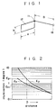
- Fig. 1 illustrates a basic principle of a gauging apparatus, in which reference numeral 11 designates a point light source located at a corner of a surface light source 12. An intensity of the light emitted from said point light source 11 is attenuated in inverse proportion to the square of the distance from said point light source 11 and exhibits an optical characteristic curve Ep as indicated in Fig. 2.
- An object 13 to be gauged perpendicularly spaced from said corner of the surface light source 12 by a distance D cm has degrees of illumination Ep1, Es1 under illuminating effects from the point light source 11 and the surface light source 12, respectively, and, in consequence, surface luminances (nits) of the object 13 corresponds to ⁇ Ep1 and ⁇ Es1, respectively, where ⁇ represents a reflection factor of said object 13.
- the ratio of these surface luminances Ep1/Es1 is a value independent of the reflection factor ⁇ of the object 13.
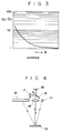
- Fig. 3 shows a characteristic curve representing such ratio of the surface luminances (EP/Es).
- EP/Es surface luminances
- the instant arrangement provides, in view of the fact that a short-circuit current of the semiconductor photoconductive element linearly responds to the incident light on a light receiving surface, an arrangement as will be described below.
- Photoconductive elements such as photodiodes which then output a photoelectrically converted current Ip corresponding to the reflected light resulting from illumination by the point light source 11 and a photoelectrically converted current Is corresponding to the reflected light resulting from illumination by the surface light source 12, respectively.
- These two photoelectrically converted currenets Ip, Is may be converted by suitable means to voltages Vp, Vs corresponding to respective surface luminances on the object 13, respectively. Namely, the relationship Ep/Es ⁇ Vp/Vs is established.
- log R log R
- a value of log R is calculated.
- the value of log R is a function of the distance, and therefore it is possible to obtain a distance D to the object 13 as an analogue information based on said value of log R.
- Figs. 4 and 5 are a schematic optical system diagram and a circuit diagram constructed according to the principle mentioned above.
- a point light source 11 comprising, for example, a light emitting diode provides illumination at a wavelength of 850 nm while a surface light source 12 provides illumination at a wavelength of 950 nm.
- the surface light source 12 comprises circuit substrate carrying a plurality of light emitting diodes arranged in matrix so as to provide a large light emitting surface.
- this surface light source 12 may be implemented by using electroluminescence (EL) elements, fluorolucent (FL) elements, etc.
- Light reflected from the object 13 illuminated by the point light source 11 and the surface light source 12 is condensed by a condenser 14 and then divided by a dichroic mirror 15 into the reflection light of 850 nm going straight through the mirror 15 onto a photoconductive element 16 and the reflection light of 950 nm is reflected by the mirror 15 onto a photoconductive element 17.
- the photoconductive elements 16, 17 comprise photodiodes, respectively, of which the output currents Ip, Is are input to logarithmic converters 18, 19, respectively.
- the logarithmic converters 18, 19 are adapted to convert said output currents Ip, Is to voltages Vp, Vs, respectively, and thereafter to convert these voltages Vp, Vs logarithmically.
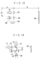
- Fig. 6 is a circuit diagram showing an example of said logarithmic converter 18, in which a diode 22 is supplied from a constant corrent source 21 with a current Ik and a voltage generated in this diode 22 is applied through an operational amplifier 23 to a log diode 24 to compensate a thermal characteristic of a forward current specific to the log diode 24.
- the current flowing though the log diode 24 is controlled by the photoconductive element 16 so that the voltage generated in the log diode 24 is logarithmically converted before input to an operational amplifier 25.
- the operational amplifier 25 provides, under a voltage gain by resistors 26, 27, a logarithmically converted voltage to the differential amplifier 20. It should be understood that the logarithmic converter 19 is identical to said logarithmic converter 20 in construction.
- a pair of point light sources 11, 12 are located at different distances from the object to be gauged as illustrated by Fig. 7 or the light source 12 is located adjacent to and integrally with the object 13 as illustrated by Fig. 8, so far as these two light sources are adapted to have their optical characteristics varying depending on their distances to the object 13.
- light projecting means including a pair of point light sources located at a same distance but one light source being located so as to project light over a wide angle and the other light source being located so as to project light over a narrow angle, with respect to the object 13 to be gauged.
- Fig. 9 shows light projecting means and light receiving means.
- the light projecting means comprises a pair of LEDs or the like serving as first and second light sources 31, 32, respectively, having optical path lengths different from each other by an amount d.
- the light receiving means comprises a photodiode or the like serving as a light receiving element 33 and a light receiving lens 34.
- Reference numeral 35 designates an object to be gauged having a diffusive reflection surface.
- the light projected by said pair of light sources 31, 32 illumiunates the object 35 and the light reflected on the object 35 is condensed by the light receiving lens 34 before its incidence onto the light receiving element 33. Then, a principle on the basis of which a distance D to be gauged is calculated will be discussed.
- a reflection factor of the object 35 is represented by ⁇
- k 1/ ⁇
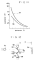
- a relationship established between the distance D to be gauged and said luminance B1 is represented by a curve 36 in Fig. 11.
- the value of D can be obtained from the constant d and the luminance ratio B2/B1 independently of the reflection factor as well as the proportional constant k.
- this gauging apparatus When this gauging apparatus is used only to determine whether the object 35 is at a distance longer or shorter than a predetermined distance, a variable C corresponding to this distance may be introduced and thereby it may be determined which of CB1 and B2 is larger than the other.
- Fig. 10 shows by way of example a signal processor in this second arrangement, in which output pulses of an oscillator 40 are transferred through a light projection change-over device 41 alternately to a first amplifier 42 and a second amplifier 43.
- said light projection change-over device 41 provides also a synchronizing signal to a light receiving change-over device 45 for timing control of light receiving.
- the first amplifier 42 and the second amplifier 43 respectively amplify the output pulses of the oscillator 40 to activate the first light source 31 and the second light source 32, respectively.
- the light reflected on the object 35 under such illumination provided from any one of said first and second light sources 31, 32 is received and photoelectrically converted by the light receiving element 33 which then outputs a light receiving signal.
- This signal is amplified by the amplifier 44 and transferred to the light receiving change-over device 45.
- the light receiving change-over device 45 determines which of the first light source 31 and the second light source 32 has been activated and, based on this determination, supplies the light receiving signal to a first arithmetic circuit 46 or a second arithmetic circuit 47.
- these first and second arithmetic circuits 46, 47 calculate said luminances B1, B2, respectively, and transfer respective results to a processor 48 so that the luminance ratio B2/B1 in the equation (6) may be calculated.
- the distance D to be gauged is calculated from this luminance ratio B2/B1 and output from an output terminal 49.
- the signal may be digitalized and arithmetically processed by a microcomputer.
- While the light projected from the first light source 31 is directed immediately to the object 35 in this embodiment, it is also possible to place a mirror or the like in the optical path of the first light source 31 to bend the optical path for certain designing reasons, so far as there is established the preveiously mentioned optical path length difference d between the first light source 31 and the second light source 32.
- the light projection from the light dsources 31, 32 preferably occurs in pulse mode and such pulse mode light projection will be effectively dealt with by a differentiator included in the amplifier 44.
- FIG. 12 A variant of the instant arrangement is shown in Fig. 12.
- the variant employs, as the light projecting means, first and second light sources 51, 52 respectively having different wavelengths. Between these light sources and an object 54 to be gauged there is provided a dichroic mirror 53 adapted to transmit or reflect the light selectively depending on the wavelength thereof. Specifically, the dichroic mirror 53 transmits the light coming from the first light source 51 but reflects the light coming from the second light source 52 so that the light coming from both the first light source 51 and the second light source 52 illuminates the object 54 lying at a distance D as viewed in Fig. 12.
- the optical path length difference d between the pair of light sources corresponds to a difference between the distance from the first light source 51 to the dichroic mirror 53 and the distance from the second light source 52 to the dichroic mirror 53.
- the light reflected on the object 54 is condensed by a light receiving lens 55 and then separated by a dichroic mirror 56 into two light components according to the wavelengths. More specifically, the light coming from the first light source 51 is transmitted by the dichroic mirrors 53, 56 and then received by a first light receiving element 57 while the light coming from the second light source 52 is reflected by the dichroic mirror 53, 56 and then received by a second light receiving element 58.
- the light receiving elements 57, 58 generate light receiving signals which are amplified, compared with each other and reflated to the distance D to be gauged, prior to being output.
- the light sources 51, 52 may be activated so as to project the illumination light in pulse mode and the output signals of the light receiving elements 57, 58 may be taken out through a suitable differentiator. In this way, the adverse affection of the ambient light can be effectively excluded.
- these dichroic mirrors 53, 56 may be replaced by suitable optical elements having polarizing ability to divide the light in two directions of polarization.
- the second light source 62, the light projecting lens 64 and the light receiving lens 66 are located at a distance D from the object 63.
- condition of 1 / F > 0 leads to a condition of
- Said virtual image point is indicated by P2 and a distance to this virtual image point is indicated by d in Fig. 13.
- the relationship established between the luminance B22 and the distance D expressed by the equation (12) corresponds to the previously mentioned curve 37 in Fig. 11.
- a variable C corresponding to this distance may be introduced and thereby it may be determined which of CB21 and B22 is larger than the other, similarly as in the secon embodiment.
- Fig. 14 shrows a variant of the said third arrangement employing a pair of light sources 71, 72 respectively of different wavelengths.
- Reference numeral 73 designates a dichroic mirror adapted for transmission or reflection of a light selectively depending on the wavelength.
- the dichroic mirror 73 as shown, reflects the light coming from the second light source 72 onto the object 63 and transmits the light coming from the first light source 71.
- a light projecting lens 74 in front of the first light source 71 and, according to the principle as shown by Fig. 15, the light having been transmitted by said light projecting lens 74 exhibits an emanating characteristic as if projected from the virtual image point.
- the light reflected on the object 63 is transmitted by a light projecting lens 75 and then directed onto a dichroic mirror 76 adapted for transmission or reflection of a light selectively depending on the wavelength.
- the light having been transmitted by this dichroic mirror 76 is received by a light receiving element 77 comprising a photodiode or the like while the light having been reflected on the dichroic mirror 76 is received by a light receiving element 78 also comprising a photodiode or the like.
- Output signals having photoelectrically converted by these light receiving elements 77, 78 are resectively amplified and then subjected to operation of comparison. In this way, the left side of said equation (13), i.e., B22/B21 is calculated and thereby the distance D to the object 63 is determined.
- the light sources 71, 72 may be activated so as to project the light in pulse mode and the output signals of the light receiving elements 77, 78 may be taken out through a suitable differentiator. In this manner, the adverse affection of the ambient light can be effectively excluded.
- the third arrangement has been described above as one of two light sources 61, 62, (71, 72) is associated with the light projecting lens 64 (74), it is also possible to associate both the light sources 61, 62 (71, 72) with the respective light projecting lenses. In this case it will be preferable to use the respective light projecting lenses which are considered to be optimal for a particular range of distance to be gauged and a particular environment in which the gauging is to be made.
- Fig. 16 shows the light projecting means used in the first embodiment including a light source 81 comprising a light emitting diode or the like, a polarizing beam splitter 82 and total reflection mirrors 83, 84, 85.
- Reference numeral 86 designates an object to be gauged.
- the light emitted from the light source 81 is split by the polarizing beam splitter 82 into polarized light components P and S. Specifically, the polarized light component P is reflected by this splitter 82 toward the object 86 while the polarized light component S is transmitted by this splitter 82, then successively reflected on the total reflection mirrors83, 84, 85, thereafter transmitted by said splitter 82 again and directed to the object 86.
- an optical path length of the polarized light component S from the light source 81 to the object 86 is longer than the corresponding optical path length of the polarized light component P by d1 + 2d2.
- the object 86 is thus illuminated according to such luminance characteristics.
- the luminances (nits) of the object 86 correspond to ⁇ Ep and ⁇ Es, respectively, where ⁇ represents a reflection factor of the object 86, Ep represents an illuminance of the polarized light component P on the object 86 and Es represents an illuminance of the polarized light component S on the object 86.
- the ratio of these two luminances Bp, Bs on the object 86 is expressed as follows: Bp/Bs ⁇ Ep/Es Therefore, the distance D to the object 86 can be calculated regardless the reflection factor ⁇ of the object 86 by detecting the luminance Bp, Bs.
- Fig. 17 shows a variant of the light projecting means used in this fourth embodiment.
- the light emitted from the light source 81 is directed by a double refractive optical element 87 onto the object 86.
- Said optical element 87 has different refractive indices depending on the polarizing direction.
- Optical path lengths of the polarized light compoenents P and S correspond to npl and nsl, respectively, where l represents the length of the optical element 87, np represents the refraction index for the polarized light component P and ns represents the refraction index for the polarized light component S.
- the distance D to the object 86 can be calculated by separately detecting the luminances on the object 86 which are due to the polarized light components P and S, respectively.
- Fig. 18 shows the light receiving means used to detect the luminances on the object 86.
- the polarizing filter 92S transmits only the polarized light component S which is then directed through a condenser 93S to the light receiving element 91.
- the signal processor is not limited to the arrangement of Fig. 5 but further varicus arrangements may be adopted such that the photoelectric signal is A/D converted to process the signal in digitalized fashion or the signal processing is performed by a divider.
- the light source 81 preferably emits pulsated or modulated light in order to exclude an influence of the ambient light.
- Fig. 20 shows light projecting means comprising a light source 101 such as a light emitting diode, a polarizisng beam splitter 102, a hyperboloidal mirror 103 and an object 104 to be gauged.
- the light emitted from the light source 101 is split by the polarizing beam splitter 102 into polarized light components P and S. Specifically, the polarized light component P is reflected by this splitter 102 toward the object 104 while the polarized light component S is transmitted by this splitter 102, then reflected by the hyperboloidal mirror 103 and transmitted again by said splitter 102 to be projected onto the object 104.
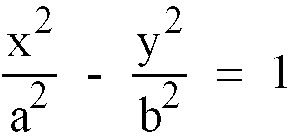
- reference numeral 105 designates a hyperbola and a locus surface formed by rotating this hyperbola 105 around the x-axis corresponds to the reflecting surface of the nyperboloidal mirror 103.
- F' - a 2 + b 2
- Respective angles ⁇ 1, ⁇ 2, ⁇ 3 are set as shown.
- the polarized light component S this corresponds to the case in which the light source lies at the focus F'.
- a direction of the reflected light coincides with the direction of the light coming from the focus F' .
- both the polarized light components P and S have their optical characteristics varying as their respective light projection distances vary.
- the luminance characteristic on the object 104 due to the polarized light component P corresponds to the curve 37 in Fig. 11 while the luminance characteristic on the same object 104 due to the polarized light component S corresponds to the curve 36 in the same figure.
- the ratio of Bp to Bs is determined by Bp Bs Ip(D+d 1 ) 2 Is D 2 Since Ip/Is is a constant, the distance D to the object 104 can be calculated based on this ratio Bp/Bs.
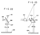
- Fig. 22 shows the light receiving means used to detect a luminance on the object 104.
- the reflection light on the object 104 which have been split into the polarized light components P and S and projected onto the object 104 is condensed by a condenser 107 and incident on a polarizing beam splitter 108.
- the polarized light component P is reflected by this beam splitter 108 and incident on one light receiving element 109 while the polarized light component S is transmitted by this splitter 108 and incident on another light receiving element 110 so that the polarized light components P, S are photoelectrically converted by these light receiving elements 109, 110, respectively.
- the luminance on the object is determined by a signal processor similar to the signal processor illustrated in Fig. 5 and the distance D is calculated from this value of luminance.
- Fig. 23 shows a variant of the light projecting means employing a rectangular prism 111 instead of the polarizing beam splitter 102.
- the slanting surface 111a of the rectangular prism 111 is provided with a reflection film for the polarizing beam splitter and a plane-convex lens 112 fixed thereon.
- Reference numeral 112a designates a total reflection mirror defined by a hyperboloidal surface.
- Light coming from the source 101 is split by the rectangular prism 111 into polarized light components P and S. More specifically, the polarized light component P is reflected on the reflection film provided on the slanting surface 111a and incident on the object 104 while the polarized light component S is transmitted by the rectangular prism 111, then reflected by the total reflection mirror 112a and transmitted again by said rectangular prism 111 before its incidence on the object 104. Since the total reflection mirror 112a is defined by the hyperboloidal surface, the light component transmitted by the rectangular prism 111 can be regarded as if projected from an imaginary light source placed at the focus F'.
- the reflection surface on which the polarized light component S is reflected is not limited to said hyperboloidal one but concave type mirror such as spheric or paraboloidal mirror may be also employed so far as one of the divided light components can be reflected by such concave mirror and have an emanating characteristic different from that of the other light component.
- the light source 101 may be activated so as to project pulsated or modulated light in order to exclude an influence of the ambient light also in the second embodiment.
Landscapes
- Physics & Mathematics (AREA)
- Engineering & Computer Science (AREA)
- Electromagnetism (AREA)
- Computer Networks & Wireless Communication (AREA)
- General Physics & Mathematics (AREA)
- Radar, Positioning & Navigation (AREA)
- Remote Sensing (AREA)
- Measurement Of Optical Distance (AREA)
- Length Measuring Devices By Optical Means (AREA)
- Optical Radar Systems And Details Thereof (AREA)
Description
- The present invention relates to an optical distance gauging apparatus utilizing the light reflected on an object to be gauged and being useful for car level gauging, spring deflection gauging, photographic distance gauging, etc.
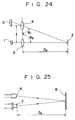
- There have already been proposed various distance gauging apparatuses utilizing the reflected light on an object to be gauged, an example of which is schematically shown by Fig. 24 of the accompanying drawings.
- This example of prior art is a distance gauging apparatus for photographic camera and based on the principle of triangulation as illustrated. With this gauging apparatus, the light emitted from a
light source 1 comprising a light emitting diode is condensed by alight projecting lens 2 and then projected onto anobject 3 to be photographed. - The light reflected on the
object 3 is condensed by alight receiving lens 4 and then focussed on a predetermined location of a light receivingelement 5 such as PSD (Poositon Sensing Device) or CCD. Consequently, a light receiving angle θ₁ depends on a position of theobject 3 and a distance Do to theobject 3 is determined from said light receiving angle θ₁ , in relation to preselected light projecting angle θ₂ and inter-lens distance ℓ. - In the case of the above-mentioned gauging apparatus shown by Fig. 24, a light spot focussed on the
light receiving element 5 is preferably as small as possible and, to achieve this, high optical properties are requred for respective parts such as thelight source 1, thelight projecting lens 2 and thelight receiving lens 4. - In the case of a short-distance gauging, the light receiving angle θ₁ is necessarily reduced but here again it is essential to focus a light image of the
object 3 as sharply as possible on thelight receiving element 5. To meet such requirement, a wide angle lens having a large image circle must be employed as thelight receiving lens 4. This leads to an increased cost and requires high mechanical precision for the light receiving angle θ₁ , the light projecting angle θ₂, the inter-lens distance ℓ, etc. - A distance from the
light source 1 to thelight projecting lens 2 must be adjusted for sharply focussing the light image of thelight source 1 on theobject 3 and similarly a distance from thelight receiving lens 4 to thelight receiving element 5 must be also adjusted for sharply focussing the light image of theobject 3 on thelight receiving element 5. A mechanism for such adjustment is inevitably complicated. - Another example of prior art illustrated by Fig. 25 is a distance gauging apparatus generally incorporated, as one of active features, into the auto-focussing mechanism for photographic camera. In this apparatus, an
object 8 to be photographed is illuminated by the light projected from alight source 6 such as a light emitting diode. The light reflected on theobject 8 is received by a light receivingelement 7 such as a photodiode. A light receiving level of the light receiving element 7 (i.e., intensity of the reflected light) is detected and a distance Do to theobject 8 is determined from the detected value. - The gauging apparatus of Fig. 25 is often disadvantageously affected by a particular environment in which the projected light is reflected on the
object 8. - Specifically, an
object 8 having a dark surface presents the light receiving level different from that which anobject 8 having a bright surface presents, because theseobjects 8 having different surfaces have correspondingly different reflection factors. Also when thelight source 6 has its light emitting surface contaminated or thelight receiving element 7 has its light receiving surface contaminated, the intensity of the emitted light or the light receiving level respectively varies. - Thus the light receiving sensitivity is affected by various conditions such as ununiform reflection factor and contaminated surface of the
object 8, or contaminated surface of thelight source 6 or thelight receiving element 7, making it difficult to gauge an accurate distance. - EP-A-0168960 discloses an optical distance gauging apparatus in which, in one embodiment, light beams from two light sources of different frequencies are fed via couplers and an optical fibre to filters which split the light into two components. The two components then pass through a lens to an object to be gauged. The light from that object then passes back through the lens, the filters and the optical fibre to light receiving means. This enables the signals corresponding to the two components to be compared to generate information corresponding to change occurring in the object or the distance thereto.
- In EP-A-0168960, the two components correspond to different wavelengths of light. The disclosure also suggests one of a single source.
- According to the present invention there is provided an optical distance gauging apparatus comprising:
light projecting means with a single light source, the light projecting means including a polarisation splitter for separating two light components (P,S) of different polarization states from the light from the single light source and to illuminate an object to be distance gauged with said two light components (P,S) with the optical path lengths being different for said two light components (P,S); light receiving means for receiving and photoelectrically converting the light reflected from the object separately for the respective light components (P,S); and a signal processor for deriving the ratio of photoelectric conversion signals for the respective light components (P,S) output from said light receiving means and thereby deriving the distance to the object. - Embodiments of the invention will now be described in detail, by way of example, with reference to the accompanying drawings, in which:
- Figs. 1 through 8 illustrate a first arrangement useful in understanding the invention, in which:
- Fig. 1 is a diagram illustrating a principle used in the invention, Fig. 2 is a characteristic graphic diagram showing the degree of illumination of on an object to be gauged under illumination by the light projected from a point light source and a surface light source, Fig. 3 is a characteristic graphic diagram showing the ratio of the degrees of illumination between the point light source and the surface light source, Fig. 4 is a diagram schematically showing light projecting means and light receiving means, Fig. 5 is a circuit diagram of a signal processor, Fig. 6 is a circuit diagram of a logarithmic converter, and Figs. 7 and 8 are schematic diagrams showing a variant of the first arrangement;
- Figs. 9 through 12 illustrate a second arrangement useful in understanding the invention, in which:
- Fig. 9 is a schematic diagram shrowing the light projecting means and the light receiving means, Fig. 10 is a block diagram showing an example of the signal processor, Fig. 11 is a characteristic graphic diagram showing illuminances on the object, and Fig. 12 is a schematic diagram showing a variant of the second arrangement;
- Figs. 13 through 15 illustrate a third arrangement useful in understanding the invention, in which:
- Fig. 13 is a schematic diagram showing the light projecting means and the light receiving means, Fig. 14 is a schematic diagram showing a variant of the third arrangement, and Fig. 15 is an optical system diagram showing an optical nature of the lens;
- Figs. 16 through 19 illustrate a first embodiment of the invention, in which:
- Figs. 16 and 17 schematically show the light projecting means, and Figs. 18 and 19 schematically show the light receiving means; and
- Figs. 20 through 23 illustrate a second embodiment of the invention, in which:
- Fig. 20 schematically shows the light projecting means, Fig. 21 is a diagram illustrating a relationship between a hyperboloidal mirror and a focus, Fig. 22 is a diagram illustrating the light receiving means, and Fig. 23 is a schematic diagram showing a variant of the second embodiment.
- A first arrangement useful in understanding the present invention will be described by way of example in reference with the accompanying drawings
- Fig. 1 illustrates a basic principle of a gauging apparatus, in which reference numeral 11 designates a point light source located at a corner of a
surface light source 12. An intensity of the light emitted from said point light source 11 is attenuated in inverse proportion to the square of the distance from said point light source 11 and exhibits an optical characteristic curve Ep as indicated in Fig. 2. - Such a square rule is not applicable to the light emitted from the
surface light source 12 and the attenuation ratio of the light with respect to the distance depends on the particular area of thesurface light source 12. In the present embodiment, thesurface light source 12 has a behaviour as represented by an optical characteristic curve Es in Fig. 2. It should be understood that thesurface light source 12 illustrated in Fig. 1 is a rectangular diffusive surface light source dimensioned a x b = 500 mm x 100mm. - An
object 13 to be gauged perpendicularly spaced from said corner of thesurface light source 12 by a distance D cm has degrees of illumination Ep₁, Es₁ under illuminating effects from the point light source 11 and thesurface light source 12, respectively, and, in consequence, surface luminances (nits) of theobject 13 corresponds to ρ Ep₁ and ρ Es₁, respectively, where ρ represents a reflection factor ofsaid object 13. - The ratio of these surface luminances Ep₁/Es₁ is a value independent of the reflection factor ρ of the
object 13. - Fig. 3 shows a characteristic curve representing such ratio of the surface luminances (EP/Es). As will be apparent from this characteristic curve, such surface luminance ratio varies as a function of the distance and this ratio may be determined to obtain the desired information about the distance of the
object 13 from the light source. - While the distance information as mentioned above can be numerically calculated by a computer after the surface luminance of the
object 13 has been measured and then the measured value has been digitally converted, such method would disadvantageously require a complicated apparatus and could not provide analogue information. - The instant arrangement provides, in view of the fact that a short-circuit current of the semiconductor photoconductive element linearly responds to the incident light on a light receiving surface, an arrangement as will be described below.
- Light reflected on the
object 13 is received by photoconductive elements such as photodiodes which then output a photoelectrically converted current Ip corresponding to the reflected light resulting from illumination by the point light source 11 and a photoelectrically converted current Is corresponding to the reflected light resulting from illumination by thesurface light source 12, respectively.
These two photoelectrically converted currenets Ip, Is may be converted by suitable means to voltages Vp, Vs corresponding to respective surface luminances on theobject 13, respectively. Namely, the relationship Ep/Es ∝ Vp/Vs is established. On the assumption that Vp/Vs = R, both sides of this equation are converted into respective logarithms as follows:

object 13 as an analogue information based on said value of log R. - Figs. 4 and 5 are a schematic optical system diagram and a circuit diagram constructed according to the principle mentioned above. In this arrangement, a point light source 11 comprising, for example, a light emitting diode provides illumination at a wavelength of 850 nm while a
surface light source 12 provides illumination at a wavelength of 950 nm. Thesurface light source 12 comprises circuit substrate carrying a plurality of light emitting diodes arranged in matrix so as to provide a large light emitting surface. Alternatively, thissurface light source 12 may be implemented by using electroluminescence (EL) elements, fluorolucent (FL) elements, etc. - Light reflected from the
object 13 illuminated by the point light source 11 and thesurface light source 12 is condensed by acondenser 14 and then divided by adichroic mirror 15 into the reflection light of 850 nm going straight through themirror 15 onto aphotoconductive element 16 and the reflection light of 950 nm is reflected by themirror 15 onto aphotoconductive element 17. - As seen in the signal processor circuit diagram of Fig. 5, the
photoconductive elements logarithmic converters - The
logarithmic converters differential amplifier 20 which, in turn, calculates a differential voltage and thereby outputs an analogue information on a distance to theobject 13 according to the equation log Vp - log Vs = log R. - Fig. 6 is a circuit diagram showing an example of said
logarithmic converter 18, in which adiode 22 is supplied from aconstant corrent source 21 with a current Ik and a voltage generated in thisdiode 22 is applied through anoperational amplifier 23 to alog diode 24 to compensate a thermal characteristic of a forward current specific to thelog diode 24. - The current flowing though the
log diode 24 is controlled by thephotoconductive element 16 so that the voltage generated in thelog diode 24 is logarithmically converted before input to anoperational amplifier 25. - The
operational amplifier 25 provides, under a voltage gain byresistors differential amplifier 20. It should be understood that thelogarithmic converter 19 is identical to saidlogarithmic converter 20 in construction. - In the case of the above-mentioned
logarithmic converters photoconductive elements - Since the same voltage characteristics are obtained when the voltages of the
photoconductive elements logarithmic converters photoconductive elements - In the arrangement described above, it is also possible that a pair of point
light sources 11, 12 are located at different distances from the object to be gauged as illustrated by Fig. 7 or thelight source 12 is located adjacent to and integrally with theobject 13 as illustrated by Fig. 8, so far as these two light sources are adapted to have their optical characteristics varying depending on their distances to theobject 13. - It is also possible to perform gauging in time series, i.e., alternatively for one of these two light sources that is being activated to project the light or in the light projected by these two light sources being selectively modulated, if desired.
- There may be also provided light projecting means including a pair of point light sources located at a same distance but one light source being located so as to project light over a wide angle and the other light source being located so as to project light over a narrow angle, with respect to the
object 13 to be gauged. - Now a second arrangement useful in understanding the invention will be described.
- Fig. 9 shows light projecting means and light receiving means. The light projecting means comprises a pair of LEDs or the like serving as first and second
light sources light receiving element 33 and alight receiving lens 34.Reference numeral 35 designates an object to be gauged having a diffusive reflection surface. - The light projected by said pair of
light sources object 35 and the light reflected on theobject 35 is condensed by thelight receiving lens 34 before its incidence onto thelight receiving element 33. Then, a principle on the basis of which a distance D to be gauged is calculated will be discussed. - Illuminance E₁ of the
object 35 under the illuminating effect of thefirst light source 31 is expressed by
first light source 31. If a reflection factor of theobject 35 is represented by ρ, a luminance B₁ of thisobject 35 is proportional to ρ E₁ and a following equation is established:
object 35 comprises a perfect diffusive surface.
curve 36 in Fig. 11. - Similarly, for the second
light source 32,

curve 37 in Fig. 11. - The reflected light passes through the
light receiving lens 34 onto thelight receiving element 33. Based on a ratio of the luminances B₁, B₂ detected in this manner, the distance D to be gauged is calculated by
- When this gauging apparatus is used only to determine whether the
object 35 is at a distance longer or shorter than a predetermined distance, a variable C corresponding to this distance may be introduced and thereby it may be determined which of CB₁ and B₂ is larger than the other. - More specifically, assumed that CB₁ = B₂ at a predetermined distance Dc, CBol > B₂ if the distance D to be gauged is longer than DC and CB₁< B₂ if the distance D is shorter than DC.
- Fig. 10 shows by way of example a signal processor in this second arrangement, in which output pulses of an
oscillator 40 are transferred through a light projection change-overdevice 41 alternately to afirst amplifier 42 and asecond amplifier 43. In response to said output pulses, said light projection change-overdevice 41 provides also a synchronizing signal to a light receiving change-overdevice 45 for timing control of light receiving. - The
first amplifier 42 and thesecond amplifier 43 respectively amplify the output pulses of theoscillator 40 to activate thefirst light source 31 and the secondlight source 32, respectively. - The light reflected on the
object 35 under such illumination provided from any one of said first and secondlight sources light receiving element 33 which then outputs a light receiving signal. This signal is amplified by theamplifier 44 and transferred to the light receiving change-overdevice 45. - The light receiving change-over
device 45 determines which of thefirst light source 31 and the secondlight source 32 has been activated and, based on this determination, supplies the light receiving signal to a firstarithmetic circuit 46 or a secondarithmetic circuit 47. - Based on this light receiving signal, these first and second
arithmetic circuits processor 48 so that the luminance ratio B₂/B₁ in the equation (6) may be calculated. - The distance D to be gauged is calculated from this luminance ratio B₂/B₁ and output from an
output terminal 49. Instead of calculating the distance D in saidprocessor 48, the signal may be digitalized and arithmetically processed by a microcomputer. - While the light projected from the
first light source 31 is directed immediately to theobject 35 in this embodiment, it is also possible to place a mirror or the like in the optical path of thefirst light source 31 to bend the optical path for certain designing reasons, so far as there is established the preveiously mentioned optical path length difference d between thefirst light source 31 and the secondlight source 32. - To exclude any adverse affection of ambient light, the light projection from the
light dsources amplifier 44. - A variant of the instant arrangement is shown in Fig. 12. The variant employs, as the light projecting means, first and second
light sources object 54 to be gauged there is provided adichroic mirror 53 adapted to transmit or reflect the light selectively depending on the wavelength thereof. Specifically, thedichroic mirror 53 transmits the light coming from thefirst light source 51 but reflects the light coming from the secondlight source 52 so that the light coming from both thefirst light source 51 and the secondlight source 52 illuminates theobject 54 lying at a distance D as viewed in Fig. 12. - In this variant, the optical path length difference d between the pair of light sources corresponds to a difference between the distance from the
first light source 51 to thedichroic mirror 53 and the distance from the secondlight source 52 to thedichroic mirror 53. - The light reflected on the
object 54 is condensed by alight receiving lens 55 and then separated by adichroic mirror 56 into two light components according to the wavelengths. More specifically, the light coming from thefirst light source 51 is transmitted by the dichroic mirrors 53, 56 and then received by a firstlight receiving element 57 while the light coming from the secondlight source 52 is reflected by thedichroic mirror light receiving element 58. - The
light receiving elements - With such modified arrangement, no alternate activation of the
light sources light sources - If the ambient light inevitably affects the reflected light coming from the
object 54, thelight sources light receiving elements - While this variant employs the
dichroic mirrors dichroic mirrors - A third arrangement useful in understanding the invention will be described.
- Fig. 13 is a schematic optical system diagram illustrating the optical system used for this embodiment, including a pair of
light sources 61, 623 such as LEDs to illuminate anobject 63 to be gauged having diffusive reflection surfaces. In front of thefirst light source 61 there is provided alight projecting lens 64 through which the light coming from thefirst light source 61 illuminates theobject 63 while the light coming from the secondlight source 62 directly illuminates theobject 63.Reference numeral 65 designates a light receiving element in fron of which there is provided alight receiving lens 66. - The light projected by the
light sources 61. 62 and reflected on theobject 63 is condensed by thelight receiving lens 66 before its incidence on thelight receiving element 65. - The second
light source 62, thelight projecting lens 64 and thelight receiving lens 66 are located at a distance D from theobject 63. - Fig. 15 illustrates the specific relationship between the
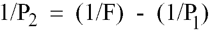
first light source 61 and thelight projecting lens 64 having a focal distance indicated by F. Assuming that thefirst light source 61 is at a distance P₁ from the projectinglens 64 and a light image of saidfirst light source 61 is focussed at a distance P₂ from saidlight projecting lens 64 as illustrated in Fig. 15, these factors are correlated by a general equation for optical lens as follows:
first light source 61 located at P₁ is directed through thelight projecting lens 64 to theobject 63, this light source should have the same emanating characteristic as when located at P₂. - Said virtual image point is indicated by P₂ and a distance to this virtual image point is indicated by d in Fig. 13.
- Now the principle on the basis of which the distance D to the
object 63 is calculated will be described. - The illuminance E₂₁ of the light projected from the
first light source 61 onto theobject 63 is expressed by theequation 
first light source 61 located at the point P₂, because the virtual image of thefirst light source 61 is formed by thelight projecting lens 64 on the point P₂. Theobject 63 will have a luminance B₂₁ which is proportional to ρ E₂₁ where ρ represents a reflection factor of theobject 63. Namely,
object 63 has its reflecting surface defined by a perfect diffusive surface. The relationship established between the luminance B₂₁ and the distance D expressed by the equation (10) is similar to the previously mentioned relationship represented by thecurve 36 in Fig. 11. - The illuminance E₂₂ of the light projected from the second
light source 62 onto theobject 63 is expressed by theequation 
light source 62. The luminance B₂₂ of theobject 63 is given by theequation 
curve 37 in Fig. 11. - The ratio of the luminances B₂₁ and B₂₂ is given by

- The distance D can be obtained by calculating the ratio of the luminance B₂₂ to the luminance B₂₁ because both K₁ and d are constants in the above equation (13). Furthermore, the value of D can be obtained independently of the reflection factor of the
object 63. It should be understood here that a signal processor to calculate the distance D may be of the same arrangement as the signal processor (Fig. 10) in the second embodiment. - If it is required only to determine whether the
object 63 is at a distance longer or shorter than a predetermined distance, a variable C corresponding to this distance may be introduced and thereby it may be determined which of CB₂₁ and B₂₂ is larger than the other, similarly as in the secon embodiment. - Fig. 14 shrows a variant of the said third arrangement employing a pair of
light sources Reference numeral 73 designates a dichroic mirror adapted for transmission or reflection of a light selectively depending on the wavelength. In this variant, thedichroic mirror 73, as shown, reflects the light coming from the secondlight source 72 onto theobject 63 and transmits the light coming from thefirst light source 71. - There is provided a
light projecting lens 74 in front of thefirst light source 71 and, according to the principle as shown by Fig. 15, the light having been transmitted by saidlight projecting lens 74 exhibits an emanating characteristic as if projected from the virtual image point. - The light reflected on the
object 63 is transmitted by alight projecting lens 75 and then directed onto adichroic mirror 76 adapted for transmission or reflection of a light selectively depending on the wavelength. The light having been transmitted by thisdichroic mirror 76 is received by alight receiving element 77 comprising a photodiode or the like while the light having been reflected on thedichroic mirror 76 is received by alight receiving element 78 also comprising a photodiode or the like. - Output signals having photoelectrically converted by these
light receiving elements object 63 is determined. - With this variant, neither alternate activation of the
light sources light sources - If the ambient light inevitably affects the reflected light coming from the
object 63, thelight sources light receiving elements - Though the third arrangement has been described above as one of two
light sources light sources 61, 62 (71, 72) with the respective light projecting lenses. In this case it will be preferable to use the respective light projecting lenses which are considered to be optimal for a particular range of distance to be gauged and a particular environment in which the gauging is to be made. - The three arrangements described above each employing a first light source and a second light source encounter a problem when the intensities of the light by these light sources vary at different rates, respectively, due to various causes such as deterioration thereof. No problem occurs so far as the intensities of the light projected by the first light source and the second light source vary at a same rate, but variation of said intensities at different rates will cause a false result of gauging.
- First and second embodiments of the invention, which will now be described, solve such problem.
- Fig. 16 shows the light projecting means used in the first embodiment including a
light source 81 comprising a light emitting diode or the like, apolarizing beam splitter 82 and total reflection mirrors 83, 84, 85.Reference numeral 86 designates an object to be gauged. - The light emitted from the
light source 81 is split by thepolarizing beam splitter 82 into polarized light components P and S. Specifically, the polarized light component P is reflected by thissplitter 82 toward theobject 86 while the polarized light component S is transmitted by thissplitter 82, then successively reflected on the total reflection mirrors83, 84, 85, thereafter transmitted by saidsplitter 82 again and directed to theobject 86. - Consequently, an optical path length of the polarized light component S from the
light source 81 to theobject 86 is longer than the corresponding optical path length of the polarized light component P by d₁ + 2d₂. - The luminance on the
object 86 illuminated by the polarized light component P split in the manner as has been described corresponds to the previously mentionedcurve 37 in Fig. 11 while a luminance on theobject 86 as being illuminated by the polarized light component S corresponds to thecurve 36 in the same figure. - The
object 86 is thus illuminated according to such luminance characteristics. In other words, the luminances (nits) of theobject 86 correspond to ρ Ep and ρ Es, respectively, where ρ represents a reflection factor of theobject 86, Ep represents an illuminance of the polarized light component P on theobject 86 and Es represents an illuminance of the polarized light component S on theobject 86. - The ratio of these two luminances Bp, Bs on the
object 86 is expressed as follows:
object 86 can be calculated regardless the reflection factor ρ of theobject 86 by detecting the luminance Bp, Bs. - Referring to Fig. 16, a distance from the
light source 81 to thepolarizing beam splitter 82 could be shortened substantially to zero with respect to the distance D to theobject 86. Assumed that said distance is zero, the illuminance of the polarized light component P on theobject 86 is expressed by Ep = 1/D while the illuminance of the polarized light component S on theobject 86 is expressed by Es = 1/(D + d), where the intensity of the light emitted by thelight source 81 is 1 and d = 2d₁ + 2d₂. - Ratio Ep to Es is given as follows:

object 86 can be determined by calculating D from the above equation (15). - Fig. 17 shows a variant of the light projecting means used in this fourth embodiment.
- As illustrated, the light emitted from the
light source 81 is directed by a double refractiveoptical element 87 onto theobject 86. - Said
optical element 87 has different refractive indices depending on the polarizing direction. Optical path lengths of the polarized light compoenents P and S correspond to npℓ and nsℓ, respectively, where ℓ represents the length of theoptical element 87, np represents the refraction index for the polarized light component P and ns represents the refraction index for the polarized light component S. - As a consequence, there occurs the situation that the polarized light components P and S have their
common light source 81 at optically different positions and therefore offer different illuminances on theobject 86. Namely, such light projecting means presents an illuminance characteristic similar to the illuminance characteristic as illustrated in Fig. 11. - Accordingly, the distance D to the
object 86 can be calculated by separately detecting the luminances on theobject 86 which are due to the polarized light components P and S, respectively. - Fig. 18 shows the light receiving means used to detect the luminances on the
object 86. - As shown, the light reflected on the
object 86 comprising a mixture of the polarized light components P and S is condensed by acondenser 88 and then incident on apolarizing beam splitter 89. The polarized light component P is reflected by thissplitter 89 toward light receivingelement 90 while the polarized light component S is transmitted by thissplitter 89 and incident on the otherlight receiving element 91, and the polarized light components P and S are photoelectrically converted by theselight receiving elements - Fig. 19 shows a variant of the light receiving means employing a pair of
polarizing filters 92P, 92S on which the light comprising a mixture of the polarized light components P, S and reflected on theobject 86 is incident. - The
polarizing filter 92P transmits only the polarized light component P which is then directed through acondenser 93P to thelight receiving element 90. - Similarly, the polarizing filter 92S transmits only the polarized light component S which is then directed through a
condenser 93S to thelight receiving element 91. - In this manner, the polarized light components P, S are photoelectrically converted by the respective
light receiving elements - In the first embodiment described above, the signal processor is not limited to the arrangement of Fig. 5 but further varicus arrangements may be adopted such that the photoelectric signal is A/D converted to process the signal in digitalized fashion or the signal processing is performed by a divider.
- The
light source 81 preferably emits pulsated or modulated light in order to exclude an influence of the ambient light. - When a light source having a wide range of wavelength is employed, the light emitted by such a light source may be split into components of different wavelengths for projection. In this case, the
polarizing beam splitter - Now a second embodiment of the invention will be described.
- Fig. 20 shows light projecting means comprising a
light source 101 such as a light emitting diode, apolarizisng beam splitter 102, ahyperboloidal mirror 103 and anobject 104 to be gauged. - The light emitted from the
light source 101 is split by thepolarizing beam splitter 102 into polarized light components P and S. Specifically, the polarized light component P is reflected by thissplitter 102 toward theobject 104 while the polarized light component S is transmitted by thissplitter 102, then reflected by thehyperboloidal mirror 103 and transmitted again by saidsplitter 102 to be projected onto theobject 104. - Since the
light source 101 is located at the focus F of thehyperboloidal mirror 103, the polarized light component S having been transmitted by thesplitter 102 can be regarded as if projected from a light source located at another focus F'. - The relationship between the
hyperboloidal mirror 103 and said focus F' will be described in reference with Fig. 21. - Referring to Fig. 21,
reference numeral 105 designates a hyperbola and a locus surface formed by rotating thishyperbola 105 around the x-axis corresponds to the reflecting surface of thenyperboloidal mirror 103. - As well known, the hyperbola is expressed by
hyperbola 105 is given by
hyperboloid 105 are given by

Respective angles θ ₁, θ₂, θ₃ are set as shown. θ₄ designates an angle defined by a line connecting the focus F to one Point (x₁, y₁) with thenormal line 106 and θ₄' designates an angle defined by a line connecting the focus F' to said one point (x₁, y₁) with thenormal line 106. - θ₄ will correspond to the incident angle of the light when the
light source 101 is placed at the focus F and therefore θ ₄= θ₄' if θ₄' is a reflection angle. As for the polarized light component S, this corresponds to the case in which the light source lies at the focus F'. - Now the condition of
θ ₄ = θ ₄' will be described in more detail. - An equation of the
hyperbola 105 at the one point (x₁, y₁) is introduced from the above equation (20) as follows:
normal line 106 at x₁, y₁ is also introduced from the above equation (21) as follows: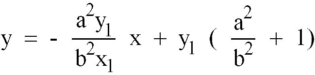
- Concerning the focuses F, F', the equations (22), (23) introduce


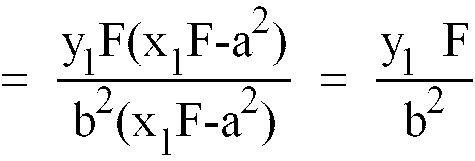

- Now the both sides of the above equation (29) are expressed in tan. Namely,
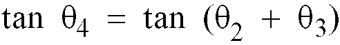


- In conclusion, the above equations (35), (40) lead to
θ ₄ = θ₄'. - It will be appreciated from the foregoing description that the light coming from the focus F is incident on the one point (x₁, y₁) at the
incident angle θ ₄ and reflected thereon at the reflection angle θ ₄'. - A direction of the reflected light coincides with the direction of the light coming from the focus F'.
- Consequently, the polarized light component S projected from the
light source 101 in Fig. 20 behaves as projected from an imaginary light source placed at the focus F' and thus exhibits an illuminance characteristic different from that of the polarized light component P. Specifically, the polarized light component P directed to theobject 104 has an optical path length of do + D while the polarized light component S has an optical path length of d₁ + D. In view of a fact that the distance do from thelight source 101 to thepolarizing beam splitter 102 can be shortened substantially to zero, it is now assumed that said distance do is zero. On this assumption, the polarized light component T will have an optical path longer than that of the polarized light component P by an amount of d₁. - In this manner, both the polarized light components P and S have their optical characteristics varying as their respective light projection distances vary. As a result, the luminance characteristic on the
object 104 due to the polarized light component P corresponds to thecurve 37 in Fig. 11 while the luminance characteristic on thesame object 104 due to the polarized light component S corresponds to thecurve 36 in the same figure. - Accordingly, the illuminance Ep of the polarized light component P on the
object 104 is given by an equation Ep Ip/D where Ip represents an effective emanating power of the polarized light component P with the reflection factor or the like of thepolarizing beam splitter 102 taken in account and theobject 104 has a luminance Bp proportional to ρ Ep where ρ represents factors of theobject 104, for example, reflection factor and diffusion factor, as expressed by
- Similarly, the illuminance Es of the polarized light component S on the
object 104 is given by an equation Es = Is/(D + d₁) where Is represents an effective emanating power of the polarized light component S and theobject 104 has a luminance Bs proportional to ρ Es where ρ represents factors of theobject 104, for example, reflection factor and diffusion factor, as expressed by
- Now the ratio of Bp to Bs is determined by

object 104 can be calculated based on this ratio Bp/Bs. - Fig. 22 shows the light receiving means used to detect a luminance on the
object 104. - As shown, the reflection light on the
object 104 which have been split into the polarized light components P and S and projected onto theobject 104 is condensed by acondenser 107 and incident on apolarizing beam splitter 108. The polarized light component P is reflected by thisbeam splitter 108 and incident on onelight receiving element 109 while the polarized light component S is transmitted by thissplitter 108 and incident on another light receiving element 110 so that the polarized light components P, S are photoelectrically converted by theselight receiving elements 109, 110, respectively. The luminance on the object is determined by a signal processor similar to the signal processor illustrated in Fig. 5 and the distance D is calculated from this value of luminance. - Fig. 23 shows a variant of the light projecting means employing a rectangular prism 111 instead of the
polarizing beam splitter 102. The slanting surface 111a of the rectangular prism 111 is provided with a reflection film for the polarizing beam splitter and a plane-convex lens 112 fixed thereon. Reference numeral 112a designates a total reflection mirror defined by a hyperboloidal surface. - Light coming from the
source 101 is split by the rectangular prism 111 into polarized light components P and S. More specifically, the polarized light component P is reflected on the reflection film provided on the slanting surface 111a and incident on theobject 104 while the polarized light component S is transmitted by the rectangular prism 111, then reflected by the total reflection mirror 112a and transmitted again by said rectangular prism 111 before its incidence on theobject 104. Since the total reflection mirror 112a is defined by the hyperboloidal surface, the light component transmitted by the rectangular prism 111 can be regarded as if projected from an imaginary light source placed at the focus F'. - It should be understood here that the reflection surface on which the polarized light component S is reflected is not limited to said hyperboloidal one but concave type mirror such as spheric or paraboloidal mirror may be also employed so far as one of the divided light components can be reflected by such concave mirror and have an emanating characteristic different from that of the other light component.
- While the invention has been described by way of example, the light receiving means is not limited to the arrangement adapted to receive the reflection light coming from the object to be gauged as in the the above-mentioned embodiments and may be also arranged so that such light receiving means is provided integrally with the object and directly receives the polarized light components P, S.
- The
light source 101 may be activated so as to project pulsated or modulated light in order to exclude an influence of the ambient light also in the second embodiment. - The signal processor is not limited to the arrangement of Fig. 5 which is adapted to log-convert the photoelectric signal coming from the light receiving means but it is also possible to employ an arrangement adapted to A/D coonvert the photoelectric signal for digital procession or an arrangement adapted to perform a desired signal processing by a divider.
Claims (7)
- An optical distance gauging apparatus comprising:
light projecting means (81 to 85) with a single light source (81), the light projecting means including a polarisation splitter (82,87,102) for separating two light components (P,S) of different polarization states from the light from the single light source (81) and to illuminate an object (86) to be distance gauged with said two light components (P,S) with the optical path lengths being different for said two light components (P,S); light receiving means (90,91) for receiving and photoelectrically converting the light reflected from the object separately for the respective light components (P,S); and a signal processor for deriving the ratio of photoelectric conversion signals for the respective light components (P,S) output from said light receiving means (90,91) and thereby deriving the distance to the object. - An optical distance gauging apparatus according to claim 1, wherein after the light coming from the single light source (81) is split into the two light components (P,S), one of said light components (S) is successively reflected on a plurality of mirrors (83 to 85) to establish the optical path length difference between said two light components (P,S).
- An optical distance gauging apparatus according to claim 1, wherein the light from the single light source (81) is projected through an optical element (87) presenting different refraction indices depending on the polarizing direction.
- An optical distance gauging apparatus according to claim 1, wherein the light projecting means is for reflecting one light component (S) on a concave mirror (103) and projecting this light component (S) together with the other light component (P) toward the object.
- An optical distance gauging apparatus according to any one of the preceding claims, wherein the light receiving means (90,91) is integral with the object (86).
- An optical distance gauging apparatus according to any one of the preceding claims, wherein the polarization splitter is a polarizing beam splitter (82).
- An optical distance gauging apparatus according to any one of claims 1 to 5, wherein the polarization splitter is a birefringent element (87)
Applications Claiming Priority (10)
| Application Number | Priority Date | Filing Date | Title |
|---|---|---|---|
| JP24351789A JPH0660818B2 (en) | 1989-09-21 | 1989-09-21 | Optical measuring device |
| JP243517/89 | 1989-09-21 | ||
| JP27148789A JPH06103183B2 (en) | 1989-10-20 | 1989-10-20 | Optical measuring device |
| JP271487/89 | 1989-10-20 | ||
| JP14534690A JPH0440315A (en) | 1990-06-05 | 1990-06-05 | Optical measuring instrument |
| JP14534590A JPH0440314A (en) | 1990-06-05 | 1990-06-05 | Optical measuring instrument |
| JP145345/90 | 1990-06-05 | ||
| JP145346/90 | 1990-06-05 | ||
| JP15165290A JPH0726844B2 (en) | 1990-06-12 | 1990-06-12 | Optical measuring device |
| JP151652/90 | 1990-06-12 |
Publications (3)
| Publication Number | Publication Date |
|---|---|
| EP0419082A2 EP0419082A2 (en) | 1991-03-27 |
| EP0419082A3 EP0419082A3 (en) | 1992-07-01 |
| EP0419082B1 true EP0419082B1 (en) | 1996-04-17 |
Family
ID=27527732
Family Applications (1)
| Application Number | Title | Priority Date | Filing Date |
|---|---|---|---|
| EP90309625A Expired - Lifetime EP0419082B1 (en) | 1989-09-21 | 1990-09-03 | Optical distance gauging apparatus |
Country Status (3)
| Country | Link |
|---|---|
| US (1) | US5056913A (en) |
| EP (1) | EP0419082B1 (en) |
| CA (1) | CA2025887C (en) |
Families Citing this family (23)
| Publication number | Priority date | Publication date | Assignee | Title |
|---|---|---|---|---|
| US5149952A (en) * | 1990-08-10 | 1992-09-22 | Stanley Electric Corporation | Optical gauging apparatus using dual beams and intermittent interruption |
| JPH04181935A (en) * | 1990-11-16 | 1992-06-29 | Canon Inc | Optical device with automatic focus detection means |
| JP3069408B2 (en) * | 1991-08-09 | 2000-07-24 | 株式会社ブリヂストン | Height sensor and air spring |
| JP3187496B2 (en) * | 1992-01-09 | 2001-07-11 | スタンレー電気株式会社 | Height sensor and air spring |
| US5512998A (en) * | 1994-06-22 | 1996-04-30 | The Titan Corporation | Contactless method and system for determining static and dynamic characteristics of target objects |
| US5825481A (en) * | 1996-05-22 | 1998-10-20 | Jervis B. Webb Company | Optic position sensor |
| US6426838B1 (en) * | 1998-11-04 | 2002-07-30 | Psc Inc. | Polarization dependant multi-focus optical system |
| US6572444B1 (en) | 2000-08-31 | 2003-06-03 | Micron Technology, Inc. | Apparatus and methods of automated wafer-grinding using grinding surface position monitoring |
| DE60228221D1 (en) * | 2002-07-03 | 2008-09-25 | Optosys Ag | Optical distance measuring device |
| US20080100820A1 (en) * | 2006-09-29 | 2008-05-01 | Mitutoyo Corporation | Range sensor using structured light intensity |
| DE102008033820B4 (en) | 2008-07-19 | 2015-06-25 | Audi Ag | Motor vehicle with active suspension |
| US8160774B2 (en) * | 2008-10-15 | 2012-04-17 | GM Global Technology Operations LLC | Vehicular actuator system |
| US8174377B2 (en) * | 2008-11-14 | 2012-05-08 | GM Global Technology Operations LLC | Suspension height sensor |
| US8175770B2 (en) * | 2008-11-17 | 2012-05-08 | GM Global Technology Operations LLC | Height sensing system for a vehicular suspension assembly |
| US8143766B2 (en) * | 2009-02-27 | 2012-03-27 | GM Global Technology Operations LLC | Harvesting energy from vehicular vibrations using piezoelectric devices |
| US8253281B2 (en) * | 2009-02-27 | 2012-08-28 | GM Global Technology Operations LLC | Energy harvesting apparatus incorporated into shock absorber |
| US8614518B2 (en) * | 2009-10-14 | 2013-12-24 | GM Global Technology Operations LLC | Self-powered vehicle sensor systems |
| US20110090482A1 (en) * | 2009-10-19 | 2011-04-21 | Capella Microsystems, Corp. | Optical position detecting device and method thereof |
| DE202011001808U1 (en) * | 2011-01-22 | 2012-04-27 | Sick Ag | Optoelectronic sensor |
| JP2014232005A (en) * | 2013-05-28 | 2014-12-11 | 富士ゼロックス株式会社 | Measurement device |
| EP3006891B1 (en) * | 2014-10-10 | 2019-04-03 | Torque and More (TAM) GmbH | Air spring with a distance measurement arrangement using infrared |
| EP3130941B1 (en) * | 2015-08-14 | 2017-10-18 | Sick Ag | Light sensor |
| US20180023943A1 (en) * | 2016-07-21 | 2018-01-25 | Sony Corporation | Optical apparatuses and method of collecting three dimensional information of an object |
Family Cites Families (8)
| Publication number | Priority date | Publication date | Assignee | Title |
|---|---|---|---|---|
| US4488813A (en) * | 1982-04-29 | 1984-12-18 | Mechanical Technology Incorporated | Reflectivity compensating system for fiber optic sensor employing dual probes at a fixed gap differential |
| JPS59180472A (en) * | 1983-03-31 | 1984-10-13 | Nec Corp | Laser radar system |
| FR2560377B1 (en) * | 1984-02-29 | 1988-05-13 | Commissariat Energie Atomique | OPTICAL DEVICE FOR MEASURING SURFACE PROXIMITY AND ITS APPLICATION TO MEASURING A SURFACE PROFILE |
| NL8401649A (en) * | 1984-05-23 | 1985-12-16 | Optische Ind De Oude Delft Nv | MEASURING SYSTEM FOR THE PRESSURE MEASUREMENT, USING A TRIANGULAR PRINCIPLE, OF THE DISTANCE BETWEEN A PARTICULAR POINT OF THE OBJECTIVE AND A REFERENCE LEVEL. |
| GB8415128D0 (en) * | 1984-06-14 | 1984-07-18 | Chaimowicz J C A | Optical displacement sensors |
| FR2591330B1 (en) * | 1985-12-11 | 1990-02-02 | Crouzet Sa | OPTOELECTRONIC POSITION AND MOVEMENT SENSOR |
| US4908508A (en) * | 1987-02-12 | 1990-03-13 | Akzo N.V. | Process and apparatus for determining thicknesses of layers |
| JPH07104477B2 (en) * | 1988-05-25 | 1995-11-13 | 株式会社精工舎 | Multi-ranger for autofocus camera |
-
1990
- 1990-09-03 EP EP90309625A patent/EP0419082B1/en not_active Expired - Lifetime
- 1990-09-05 US US07/578,083 patent/US5056913A/en not_active Expired - Lifetime
- 1990-09-20 CA CA002025887A patent/CA2025887C/en not_active Expired - Fee Related
Also Published As
| Publication number | Publication date |
|---|---|
| EP0419082A3 (en) | 1992-07-01 |
| US5056913A (en) | 1991-10-15 |
| CA2025887C (en) | 2001-11-20 |
| EP0419082A2 (en) | 1991-03-27 |
| CA2025887A1 (en) | 1991-03-22 |
Similar Documents
| Publication | Publication Date | Title |
|---|---|---|
| EP0419082B1 (en) | Optical distance gauging apparatus | |
| US4514083A (en) | Distance measuring apparatus | |
| US4739161A (en) | Fine displacement transducer employing plural optical fibers | |
| US6388754B1 (en) | Shape measuring system and method | |
| US6654061B2 (en) | Automatic focus adjusting apparatus and method utilized by an image sensing apparatus | |
| JPH0627706B2 (en) | Reflectance measuring device | |
| US4117325A (en) | Optical objective focus indicator and display | |
| US6433330B1 (en) | Sun optical limitation illumination detector (SOLID) | |
| JPS62223634A (en) | Color deciding device | |
| EP0223485A2 (en) | Absorption gauge for determining the thickness, moisture content or other parameter of a film or coating | |
| US4733062A (en) | Focus detecting device | |
| US4307947A (en) | Focus detecting device for camera | |
| US4745426A (en) | Light measuring device for a camera | |
| US4716284A (en) | Photographic optical system having enhanced spectral transmittance characteristics | |
| JPH04283683A (en) | Lightwave ranging device | |
| JPH11337812A (en) | Autofocus device | |
| CA2048912A1 (en) | Optical gauging apparatus | |
| GB2095505A (en) | Automatic focusing | |
| JPH08128806A (en) | Optical displacement sensor | |
| US5668626A (en) | Distance measuring apparatus | |
| JPH0493706A (en) | Optical measuring apparatus | |
| JPH0210282A (en) | Laser radar system | |
| JPH0558483B2 (en) | ||
| SU1130827A1 (en) | Device for lens focusing | |
| JPH0440315A (en) | Optical measuring instrument |
Legal Events
| Date | Code | Title | Description |
|---|---|---|---|
| PUAI | Public reference made under article 153(3) epc to a published international application that has entered the european phase |
Free format text: ORIGINAL CODE: 0009012 |
|
| AK | Designated contracting states |
Kind code of ref document: A2 Designated state(s): DE FR GB |
|
| PUAL | Search report despatched |
Free format text: ORIGINAL CODE: 0009013 |
|
| AK | Designated contracting states |
Kind code of ref document: A3 Designated state(s): DE FR GB |
|
| 17P | Request for examination filed |
Effective date: 19921218 |
|
| 17Q | First examination report despatched |
Effective date: 19931006 |
|
| GRAH | Despatch of communication of intention to grant a patent |
Free format text: ORIGINAL CODE: EPIDOS IGRA |
|
| RBV | Designated contracting states (corrected) |
Designated state(s): GB |
|
| GRAA | (expected) grant |
Free format text: ORIGINAL CODE: 0009210 |
|
| REG | Reference to a national code |
Ref country code: DE Ref legal event code: 8566 |
|
| AK | Designated contracting states |
Kind code of ref document: B1 Designated state(s): GB |
|
| PLBE | No opposition filed within time limit |
Free format text: ORIGINAL CODE: 0009261 |
|
| STAA | Information on the status of an ep patent application or granted ep patent |
Free format text: STATUS: NO OPPOSITION FILED WITHIN TIME LIMIT |
|
| 26N | No opposition filed | ||
| PGFP | Annual fee paid to national office [announced via postgrant information from national office to epo] |
Ref country code: GB Payment date: 19990824 Year of fee payment: 10 |
|
| PG25 | Lapsed in a contracting state [announced via postgrant information from national office to epo] |
Ref country code: GB Free format text: LAPSE BECAUSE OF NON-PAYMENT OF DUE FEES Effective date: 20000903 |
|
| GBPC | Gb: european patent ceased through non-payment of renewal fee |
Effective date: 20000903 |