WO2021039291A1 - 送風機 - Google Patents
送風機 Download PDFInfo
- Publication number
- WO2021039291A1 WO2021039291A1 PCT/JP2020/029531 JP2020029531W WO2021039291A1 WO 2021039291 A1 WO2021039291 A1 WO 2021039291A1 JP 2020029531 W JP2020029531 W JP 2020029531W WO 2021039291 A1 WO2021039291 A1 WO 2021039291A1
- Authority
- WO
- WIPO (PCT)
- Prior art keywords
- motor
- fan
- fan case
- blower
- holder
- Prior art date
Links
Images


Classifications
-
- F—MECHANICAL ENGINEERING; LIGHTING; HEATING; WEAPONS; BLASTING
- F04—POSITIVE - DISPLACEMENT MACHINES FOR LIQUIDS; PUMPS FOR LIQUIDS OR ELASTIC FLUIDS
- F04D—NON-POSITIVE-DISPLACEMENT PUMPS
- F04D25/00—Pumping installations or systems
- F04D25/02—Units comprising pumps and their driving means
- F04D25/08—Units comprising pumps and their driving means the working fluid being air, e.g. for ventilation
- F04D25/082—Units comprising pumps and their driving means the working fluid being air, e.g. for ventilation the unit having provision for cooling the motor
-
- F—MECHANICAL ENGINEERING; LIGHTING; HEATING; WEAPONS; BLASTING
- F04—POSITIVE - DISPLACEMENT MACHINES FOR LIQUIDS; PUMPS FOR LIQUIDS OR ELASTIC FLUIDS
- F04D—NON-POSITIVE-DISPLACEMENT PUMPS
- F04D25/00—Pumping installations or systems
- F04D25/02—Units comprising pumps and their driving means
- F04D25/08—Units comprising pumps and their driving means the working fluid being air, e.g. for ventilation
-
- A—HUMAN NECESSITIES
- A01—AGRICULTURE; FORESTRY; ANIMAL HUSBANDRY; HUNTING; TRAPPING; FISHING
- A01G—HORTICULTURE; CULTIVATION OF VEGETABLES, FLOWERS, RICE, FRUIT, VINES, HOPS OR SEAWEED; FORESTRY; WATERING
- A01G20/00—Cultivation of turf, lawn or the like; Apparatus or methods therefor
- A01G20/40—Apparatus for cleaning the lawn or grass surface
- A01G20/43—Apparatus for cleaning the lawn or grass surface for sweeping, collecting or disintegrating lawn debris
- A01G20/47—Vacuum or blower devices
-
- F—MECHANICAL ENGINEERING; LIGHTING; HEATING; WEAPONS; BLASTING
- F04—POSITIVE - DISPLACEMENT MACHINES FOR LIQUIDS; PUMPS FOR LIQUIDS OR ELASTIC FLUIDS
- F04D—NON-POSITIVE-DISPLACEMENT PUMPS
- F04D25/00—Pumping installations or systems
- F04D25/02—Units comprising pumps and their driving means
- F04D25/06—Units comprising pumps and their driving means the pump being electrically driven
- F04D25/0673—Battery powered
-
- F—MECHANICAL ENGINEERING; LIGHTING; HEATING; WEAPONS; BLASTING
- F04—POSITIVE - DISPLACEMENT MACHINES FOR LIQUIDS; PUMPS FOR LIQUIDS OR ELASTIC FLUIDS
- F04D—NON-POSITIVE-DISPLACEMENT PUMPS
- F04D29/00—Details, component parts, or accessories
- F04D29/40—Casings; Connections of working fluid
- F04D29/52—Casings; Connections of working fluid for axial pumps
- F04D29/54—Fluid-guiding means, e.g. diffusers
- F04D29/541—Specially adapted for elastic fluid pumps
- F04D29/542—Bladed diffusers
-
- F—MECHANICAL ENGINEERING; LIGHTING; HEATING; WEAPONS; BLASTING
- F04—POSITIVE - DISPLACEMENT MACHINES FOR LIQUIDS; PUMPS FOR LIQUIDS OR ELASTIC FLUIDS
- F04D—NON-POSITIVE-DISPLACEMENT PUMPS
- F04D29/00—Details, component parts, or accessories
- F04D29/40—Casings; Connections of working fluid
- F04D29/52—Casings; Connections of working fluid for axial pumps
- F04D29/54—Fluid-guiding means, e.g. diffusers
- F04D29/541—Specially adapted for elastic fluid pumps
- F04D29/545—Ducts
-
- F—MECHANICAL ENGINEERING; LIGHTING; HEATING; WEAPONS; BLASTING
- F04—POSITIVE - DISPLACEMENT MACHINES FOR LIQUIDS; PUMPS FOR LIQUIDS OR ELASTIC FLUIDS
- F04D—NON-POSITIVE-DISPLACEMENT PUMPS
- F04D29/00—Details, component parts, or accessories
- F04D29/58—Cooling; Heating; Diminishing heat transfer
- F04D29/5806—Cooling the drive system
-
- F—MECHANICAL ENGINEERING; LIGHTING; HEATING; WEAPONS; BLASTING
- F04—POSITIVE - DISPLACEMENT MACHINES FOR LIQUIDS; PUMPS FOR LIQUIDS OR ELASTIC FLUIDS
- F04D—NON-POSITIVE-DISPLACEMENT PUMPS
- F04D29/00—Details, component parts, or accessories
- F04D29/66—Combating cavitation, whirls, noise, vibration or the like; Balancing
- F04D29/661—Combating cavitation, whirls, noise, vibration or the like; Balancing especially adapted for elastic fluid pumps
Definitions
- the present invention relates to a portable blower that sucks air into the housing from an intake port by rotation of a fan housed in the main body housing and discharges the air from the discharge port to the outside of the main body housing.
- the blower described in Patent Document 1 is known as a conventional portable blower.
- This blower has a configuration in which external air is taken in from a suction port formed in a housing by a fan driven by a motor, and the sucked air is blown out to an arbitrary region through a nozzle attached to an air outlet.
- the operator holds the handle of the blower and works while pointing the tip of the nozzle at the area to be blown out.
- Work with a blower includes, for example, the work of blowing off dust on the ground. Hold the handle so that the nozzle points diagonally forward and downward, and shake the housing of the main body left and right to swing the tip of the nozzle left and right. Blow away dust on the ground.
- a centrifugal fan or an axial fan was used as the blower, and the intake port (opening) of the housing for taking in the air passing through the fan was arranged in the vicinity of the motor.
- the motor is arranged near the axial center of the main body housing while accommodating the entire motor through the motor casing inside the substantially tubular main body housing.
- the motor casing has an inner cylinder portion for accommodating the motor and an outer cylinder portion in contact with the inner surface of the housing, and a stationary blade portion extending radially between the inner cylinder and the outer cylinder is formed in the housing. It produces a rectifying effect on the air flowing through the housing, improving the ventilation performance and reducing noise.
- a separate rectifying cone is attached to the downstream opening of the inner cylinder portion that holds the motor, and a plurality of auxiliary vanes extending outward are formed on the outer surface of the rectifying cone.
- a portable blower it is desirable to increase the axial length of the vane in order to enhance the rectifying effect of the vane.
- an increase in the size of the stationary blade causes an increase in the size of the motor casing, and as a result, the housing becomes large and the weight increases, which impairs the portability of the blower. ..
- the inner cylinder portion of the motor casing accommodates the entire motor, the cooling performance of the motor is impaired. Therefore, it is necessary to design the motor in consideration of cooling measures.
- the present invention has been made in view of the above background, and an object of the present invention is to provide a blower capable of improving ventilation performance and reducing noise while avoiding an increase in the size of a housing. Another object of the present invention is to provide a blower having improved cooling performance of a motor. Still another object of the present invention is a blower that suppresses an increase in manufacturing cost by devising the shape of the stationary blade formed on the inner wall portion of the housing so that the stationary blade can be molded by injection molding similar to the conventional one. Is to provide.
- a motor having a rotating shaft, a fan that rotates by the driving force of the motor and generates an air flow in the axial direction of the rotating shaft, and a tubular shape extending in the axial direction are formed and have a diameter.
- a tubular motor holder that holds the motor inside the direction
- a fan case that is formed in a tubular shape that extends in the axial direction and accommodates the motor, motor holder, and fan to form an air flow path, and a fan case.
- a blower having a housing including a handle portion gripped by an operator, a first rectifying portion is formed radially inside the fan case.
- the first rectifying portion is a plurality of ribs protruding inward from the inner peripheral surface of the fan case, and may be integrally formed with the housing.
- the motor holder is configured to have a length in the axial direction shorter than that of the motor.
- the fan case is formed of two members divided in the left-right direction perpendicular to the axial direction, and the plurality of ribs are configured to extend in the left-right direction.
- the present invention can be easily realized only by changing the shape of the mold at the time of injection molding of the housing.
- the plurality of ribs extend from the inner peripheral surface in the direction orthogonal to the dividing surface of the two members.
- the shape of the rib on the side separated from the fan in the axial direction is formed so as to approach the rotation axis, and the side of the rib close to the fan includes a portion inclined and extending with respect to the rotation axis. It is composed.
- the motor has a covering portion whose radial outer side is covered by the motor holder and an exposed portion whose radial outer side is not covered by the motor holder.
- the fan case portion of the housing has a tapered portion that is narrowed so that the diameter decreases as the distance from the motor increases in the axial direction on the downstream side of the motor in the air flow flow path direction, and most of the first rectifying portion. Or all of them are arranged in the tapered portion.
- the first rectifying portion may be configured to include a first supporting portion that abuts and supports the outer peripheral surface of the bearing holder of the motor.
- the motor holder has a second straightening vane that is integrally molded radially outward.
- the second rectifying portion is formed on the second supporting portion that abuts on the motor and the fan case to support the motor. Further, the second rectifying unit is brought into contact with the fan case via an elastic body.
- the second straightening vane is configured to include a first rib extending in the radial direction and a second rib extending obliquely in the axial direction.
- the first rectifying portion is formed on the inner peripheral side of the fan case, the swirling flow of the air discharged from the fan can be attenuated, the ventilation performance can be improved, and the noise can be reduced. ..
- the second rectifying portion is formed in the motor holder, it is possible to support the motor in addition to rectifying the wind emitted from the fan.
- the motor holder supports a part of the motor without covering the entire motor, the outer surface of the motor is exposed to the air flow, and the cooling performance of the motor is improved. Further, since the entire outer surface of the motor is not covered, the size and weight of the motor holder can be reduced, and the weight of the entire blower can be reduced.
- FIG. 1 It is a perspective view which shows the whole structure of the blower 1 which concerns on embodiment of this invention. It is a perspective view of the state where the housing 2 and the nozzle 50 on the left side of the blower 1 of FIG. 1 are removed. It is a vertical cross-sectional view in the state which the housing 2 on the left side of the blower 1 of FIG. It is a horizontal sectional view which passes through the rotation axis A1 of the blower 1 of FIG. It is a perspective view which shows the mounting state of the housing 2 and the motor holder on the right side of the blower 1 of FIG. 1, and is the figure which showed the direction of the wind flowing in the housing 2. It is a side view of FIG. 5, and is the figure which showed the flow of the wind.
- the cordless portable blower 1 includes, for example, a motor 11 (described later in FIG. 2) and a fan 16 (described later in FIG. 2) inside a resin housing 2, and the electric power of the battery pack 80. Drives a motor 11 (not shown). The air flow generated by the rotation of the fan 16 (not shown) is injected forward via the nozzle 50. The operator grips the handle portion 5 of the blower 1 to perform the work. Generally, the blower 1 is held with the nozzle 50 facing diagonally forward and downward, and the handle portion 5 is shaken back and forth and left and right to shake the tip of the nozzle 50 back and forth and left and right while removing dust from the area to be cleaned such as a desk or floor. blow off.
- the housing 2 has a fan case portion 3 having a shape in which the diameter near the center in the front-rear direction bulges, a battery mounting portion 4 formed in a thin cylinder on the rear side of the fan case portion 3, and a center of the fan case portion 3. It is composed of a handle portion 5 that connects the portion and the rear side of the battery mounting portion 4 and a cylindrical tip portion 6 formed on the front side of the fan case portion 3, and these are integrally manufactured by molding a synthetic resin. ..
- the housing 2 is molded in a state of being divided into two by the left and right center divided surfaces, and is fixed by a plurality of screws described later.
- a plurality of screw bosses 18a to 18m (18c and 18i to 18m are not visible in FIG. 1) are formed on the left side portion of the housing 2, and screw bosses having screw holes are formed on the right side portion of the housing 2 at positions corresponding to them.
- the handle portion 5 is a portion gripped by an operator with one hand, and the front portion of the handle portion 5 is formed with a front connection portion 5b extending in a substantially vertical direction and is connected to the upper surface of the fan case portion 3 to be connected to the rear side.
- the rear connection portion 5c of the portion is connected to the rear end portion of the battery mounting portion 4.
- a switch panel 40 for turning on or off the motor 11 (described later in FIG. 2) is provided on the upper side of the grip portion 5a of the handle portion 5.
- First intake ports 7a are formed on the left and right side surfaces of the front connecting portion 5b of the handle portion 5.
- the first intake port 7a is an opening for sucking outside air here, and has a plurality of slits having an elongated shape in the horizontal direction.
- Second intake ports 7b are provided on the left and right side surfaces on the rear side of the battery mounting portion 4.
- the first intake port 7a and the second intake port 7b serve as the intake ports of the blower 1.
- the battery pack 80 is mounted under the battery mounting portion 4 of the housing 2.
- the battery mounting portion 4 is formed with two rail portions (not visible in the figure) extending horizontally in the front-rear direction with a predetermined distance in the left-right direction, and the battery pack 80 is a rail portion. It is attached by horizontally moving the housing 2 from the rear side to the front side along the above. When removing the battery pack 80 from the housing 2, the battery pack 80 is horizontally moved to the rear side of the housing 2 while pushing the latch buttons 81 provided on both the left and right side surfaces.
- the battery pack 80 is widely used in power tools, and has a plurality of battery cells (not shown) housed inside a case made of synthetic resin.
- the battery cell is a secondary battery that can be repeatedly charged and discharged, and a known battery cell such as a lithium ion battery cell is used.
- the output of the battery pack 80 is, for example, DC 18V or 36V, but the voltage is arbitrary.
- the blower 1 When the battery pack 80 is mounted on the housing 2, the blower 1 can be stably placed on a desk or the like by the bottom surface of the battery pack 80 and the legs 8 formed on the front side of the housing 2.
- the leg portion 8 is manufactured integrally with the fan case portion 3 by molding a synthetic resin.
- the nozzle 50 is a separate component connected to the opening 6a formed on the front side of the tip portion 6 of the housing 2, and has a tapered shape in which the diameter of the tip is small and gradually increases toward the rear in the axis A1 direction from the discharge port 51. It is formed.
- the nozzle 50 has a predetermined axial length in order to increase the flow velocity by narrowing the flow path of the air discharged from the tip portion 6 and to make it easier to apply the air flow to a specific object.
- the nozzle 50 is manufactured by integrally molding a synthetic resin.
- the nozzle connected to the tip portion 6a is not limited to the nozzle 50 having the shape shown in FIG. 1, and there are various nozzles such as a nozzle in which the tip of a cylindrical straight pipe is bent flat and a curved pipe. Nozzle or extension pipe may be used.
- FIG. 2 is an exploded perspective view of the blower 1 according to the embodiment of the present invention, showing a state in which the nozzle 50 and the left side portion of the housing 2 are removed.
- the housing 2 is composed of a fan case portion 3, a battery mounting portion 4, a handle portion 5, and a tip portion 6, and is divided into left and right parts on a vertical plane passing through the rotation axis of the motor 11. Screw bosses 17a to 17m having screw holes are formed on the right side part of the housing 2, and are fixed to the left side part of the housing 2 by screws (not shown).
- the fan case portion 3 is a part of the housing 2 and is formed in a tubular shape for accommodating the motor 11 and the fan 16 inside. Inside the fan case portion 3, the motor 11 is held at a position concentric with the axial center of the tip portion 6 by the motor holder 30.
- the motor 11 is a DC motor with a brush housed in a metal casing.
- a centrifugal cooling fan 14 is provided inside the motor 11.
- a fan 16 is provided on the rotating shaft 11a (see FIG. 3 described later for reference numerals) that protrudes to the rear side of the motor 11.
- the fan 16 is manufactured by integrally molding a synthetic resin, and a plurality of curved blades 16b extending diagonally forward in the axial direction are formed from the central rotating shaft portion 16a, and a cone is formed so as to connect the outer edges of the blades 16b.
- a shaped shroud 16c is provided.
- the rotation axis of the motor 11 (not visible in the figure) is arranged coaxially with the axis A1 (see FIGS. 1 and 3), and the fan 16 is pivotally supported via the rotation axis of the motor 11.
- the motor holder 30 is formed by integrally molding synthetic resin, and an outer cylinder portion 36 that contacts the inner wall surface of the housing 2 is formed on the outer side in the radial direction, and the outer peripheral surface of the casing of the motor 11 is located near the axis A1.
- An inner cylinder portion 32 to be abutted is formed. Ribs or the like extending in the radial direction are formed between the inner cylinder portion 32 and the outer cylinder portion 36, and the outer cylinder portion 36 and the inner cylinder portion 32 are fixed so as to be concentric.
- the shape of the motor holder 30 will be described in detail with reference to FIG. 7 and the like.
- the handle portion 5 includes a grip portion 5a gripped by an operator, a front connection portion 5b for connecting the front end of the grip portion 5a and the fan case portion 3, and a rear end of the grip portion 5a after connecting the fan case portion 3. It is formed by the side connecting portion 5c.
- the front connecting portion 5b of the handle portion 5 and the front connecting portion of the fan case portion 3 are partitioned so that air cannot flow.
- the connection portion on the rear side between the handle portion 5 and the fan case portion 3 is configured so that the internal space communicates with each other, and the air is configured to flow between the handle portion 5 and the fan case portion 3.
- the outside air taken in through the first intake port 7a flows to the rear side inside the handle portion 5, flows from the rear to the front side in the space inside the battery mounting portion 4, and is sucked from the second intake port 7b. It merges with the air and reaches the fan 16.
- the air discharged from the fan 16 to the front side passes through the inside of the outer cylinder portion 36 of the motor holder 30 and reaches the space accommodated by the motor 11 (internal space of the fan case portion 3) from the tip portion 6. It is discharged to the nozzle 50 (FIG. 1 side) side.
- the cooling fan 14 sucks air from the opening on the back surface (front side in FIG. 1) of the casing of the motor 11 and discharges the air outward in the radial direction.
- the length of the inner cylinder portion 32 of the motor holder 30 in the axis A1 direction is sufficiently shorter than the length of the motor 11 (however, the rotating shaft is not included in the length).
- a region of more than half of the outer peripheral surface of the casing of the motor 11 is exposed in the air passage through which the air for blowing air flows.
- the portion exposed in the air passage is defined as the motor exposed portion 38
- the portion covered by the motor holder 30 is defined as the motor covering portion 37 (see FIG. 4 below for reference numerals). Since the cylindrical casing of the motor 11 is made of metal, the cooling performance of the motor 11 can be improved by sufficiently securing the exposed portion 38 of the motor. Further, by providing the motor exposed portion 38, the opening portion 13 can be exposed in the air passage in the fan case portion 3, so that the cooling performance inside the motor 11 can be sufficiently achieved.
- a convex bearing holder 15a (described later in FIG. 3) protruding outward in the axis A1 direction is fixed to the motor support rib (first support portion) 25 and the housing 2.
- a damper 28 is attached between the housings 2 by the motor support rib 25 for vibration absorption.
- the motor support rib 25 is formed so as to extend from the inner wall portion of the fan case portion 3 in the direction of the divided surface, and is integrally molded with the housing 2.
- a curved second guide portion 27 is formed on the front side of the motor support rib 25.
- the second guide portion 27 forms a curved slope that is continuous forward from the upper surface and the lower surface of the motor support rib 25, and the tips of the upper slope and the lower slope are connected to each other.
- a curved first guide portion 26 is formed on the front side of the motor support rib 25 to prevent air turbulence on the rear surface side of the motor support rib 25. Most of the air flowing through the outer peripheral portion of the motor 11 flows inside the nozzle 50 connected to the tip portion 6, and a part of the air is sucked rearward into the internal space of the motor 11 through the suction hole 15c.
- the second guide portion 27 is a guide plate for rectifying the air flow on the downstream side of the motor support rib 25, and is prevented from disturbing the air flow on the downstream side of the motor 11.
- a plate-shaped first wing 21 and second wing 22 (see FIG. 5 described later) and a third wing 23 (described later) extending to the left from the inner wall 5) and the fourth wing 24 are formed.
- These four blades form a first stationary blade 20 formed to rectify the air flow inside the fan case 3.
- FIG. 2 only a part 22a and 23a on the front side of the second wing 22 and the third wing 23 can be seen, but the shapes of the second wing 22 and the third wing 23 will be described in detail in FIG.
- the first to fourth blades 21 to 24 are examples of the first rectifying unit.
- the switch panel 40 is arranged on the upper surface of the switch unit 41 equipped with the on button for rotating the motor 11, the off button for stopping the rotation, and the battery warning lamp, and the circuit board 42 is below the switch unit 41. Provided.
- the on button of the switch panel 40 When the on button of the switch panel 40 is pressed, the motor 11 rotates, so that the fan 16 rotates, and the first intake port 7a formed in the handle portion 5 and the rear end side surface of the battery mounting portion 4 are formed.
- (2) Outside air is sucked from the intake port 7b.
- the sucked air reaches the fan 16 from the internal space of the battery mounting portion 4, passes between the inner cylinder portion 32 and the outer cylinder portion 36 of the motor holder 30, flows forward around the motor 11, and the tip portion. It reaches the nozzle 50 (see FIG. 1) from 6.
- FIG. 3 is a vertical cross-sectional view of the blower 1 of FIG. 2 passing through the rotation axis A1.
- the fan case portion 3 has a tapered portion 3a that tapers from the cylindrical tip portion 6 side to the large diameter portion that holds the motor holder 30, and is connected to the battery mounting portion 4 from the rear side of the large diameter portion. It has a shape that tapers to the vicinity of the part.
- the motor 11 is mounted rearward from the motor holder 30 to the front side portion.
- a metal mounting member 19 is provided at the rear end of the rotating shaft 11a of the motor 11, and a fan 16 for blowing air is mounted on the mounting member 19.
- the motor 11 is arranged so that the rotating shaft 19 is concentric with the axis A1.
- the fan 16 is formed with a plurality of blades 16b extending rearward in the axis A1 direction from the outer peripheral side of the rotating shaft portion 16a whose diameter is expanded like an umbrella.
- a conical shroud 16c is connected to the rear edge of the blade 16b.
- the motor holder 30 is held so that the outer peripheral portion of the outer cylinder portion 36 is sandwiched between the right side part and the left side part of the housing 2.
- a convex portion 36a is formed on the upper side of the outer cylinder portion 36, and is held in the concave portion 3d of the housing 2 via the elastic body 48.
- the outer cylinder portion 36 is an example of the second support portion.
- the elastic body 48 is a block body made of rubber and having a space (recessed portion) for accommodating the convex portion 36a.
- a convex portion 36a is formed on the lower side of the motor holder 30 and is held in the concave portion 3d of the housing 2 via the elastic body 48.
- the motor 11 is a brushed DC motor housed in a cylindrical metal casing, and a rear portion thereof is housed in an inner cylinder portion 32 of the motor holder 30. That is, the inner cylinder portion 32 becomes a portion (motor accommodating portion) for accommodating the motor 11.
- Two screw holes are formed in the rear wall portion 31 of the motor holder 30, and the motor 11 is fixed by the screws 44 extending in the direction parallel to the axis A1.
- the rear portion of the motor 11 is configured as a motor covering portion 37 whose outer peripheral surface is covered by the motor holder 30, and the bearing holder 15b formed on the rear end wall of the motor 11 is held by the motor support rib 25.
- a rubber damper 28 is provided between the bearing holder 15b and the motor support rib 25.
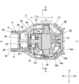
- FIG. 4 is a horizontal cross-sectional view of the blower 1 of FIG. 1 passing through the rotation axis A1.
- the motor 11 is arranged at the center position on the left and right so that its rotation axis coincides with the axis A1.
- the fan 16 attached to the rotation shaft (output shaft) 14 (not shown) of the motor 11 is rotated, so that the air flow in the directions indicated by the arrows F1 to F5. Is generated.
- the inner wall surface of the fan case portion 3 narrowed in a tapered shape from the front to the rear functions as a fan guide for guiding the air flowing into the fan 16 in a predetermined direction (front).
- the shroud 16c of the fan 16 is arranged at a position close to the inner wall surface of the fan case 3 so as to maintain a certain gap.
- a circular opening 16d is formed on the rear side of the shroud 16c near the axis A1, and the fan 16 rotates to suck air in the battery mounting portion 4 from the opening 16d along the umbrella-shaped rotating shaft portion 16a. As shown by the arrow F1, the air flows outward in the radial direction and is discharged to the front side.
- the air discharged from the fan 16 passes through the inside of the motor holder 30 as shown by the arrow F2. That is, the air flow passes through the opening 39b (described later in FIG. 9) between the inner cylinder portion 34 and the outer cylinder portion 36 (both of which are referred to later in FIG. 5), and any one of the first stationary blade portions 20.
- the blade in this example, flows above the third wing 23 as shown by an arrow F3, flows through the upper left side of the motor support rib 25 and the upper part of the second guide portion 27 as shown by an arrow F4, and flows as shown by an arrow F4, and the internal space of the tip portion 6 That is, it reaches the internal space of the nozzle 50.
- the third wing 23 is formed so as to project from the inner wall surface of the fan case portion 3 toward the axis A1 direction, and the inner peripheral side edge portion 23b thereof is formed with the motor 11. It is at a position ten separated and is not close to the outer peripheral surface of the motor 11. Therefore, a part of the air flowing inside the third wing 23 comes into contact with the rear surface of the motor support rib 25 and the direction is inside. After that, the air flowing as shown by the arrow F5 flows from the suction hole 15c to the internal space of the motor 11 by the suction of the cooling fan 14.
- the flows of arrows F1 to F4 in FIG. 4 indicate the air flow flowing from the rear to the front in the space on the left side of the motor 11 among the air discharged from the fan 16, but the space on the right side of the motor 11 is shown.
- the air flow flowing from the rear to the front reaches the tip 6 in the same manner.
- the inner wall surface on the front side of the fan case portion 3 of the housing 2 has a shape of a leading throttle toward the cylindrical tip portion 6, and is forward along the outer peripheral surface of the motor 11 and the inner wall surface of the fan case portion 3 in the A1 direction.
- the air flow F4 flowing toward is collected and guided to the tip portion 6 formed in a cylindrical shape.
- An annular groove 6b for attaching a mesh-like guard (not shown) for preventing foreign matter from entering from the tip portion 6 is formed in the vicinity of the rear end of the cylindrical portion of the tip portion 6. Further, the air flow flowing from the rear to the front in the spaces above and below the motor 11 also reaches the tip portion 6 in the same flow, but at this time, the upper space and the lower space corresponding to the arrow F3 are used for guidance.
- the first stationary wing portion is not formed.
- the outer diameter of the fan case portion 3 of the housing 2 has substantially the same horizontal and vertical cross sections, a large diameter at the center in the axis A1 direction is formed, and the front side and the rear side thereof are narrowed down in a tapered shape. ..
- the motor 11 is positioned at the center of the fan case portion 3 in the left-right direction by a motor holder 30 having an outer cylinder portion 36 and an inner cylinder portion 32 (see FIG. 2 for reference numerals), and the axis A1 and the rotation axis of the motor 11 are concentric. Is placed in.
- the air that has passed through the tip portion 6 reaches the internal space of the nozzle 50.
- Two convex portions 52 are formed on the outer peripheral surface near the rear end of the nozzle 50, and engage with the mounting groove portion 9 of the tip portion 6.
- FIG. 5 is a perspective view showing the mounting state of the housing 2 and the motor holder 30 on the right side of the blower 1 of FIG. 1, and is a view showing the direction of the wind flowing in the housing 2.
- the air flow indicated by arrows F1 to F5 corresponds to the air flow shown in FIG.
- the arrows F1 and F2 also flow backward in the axial direction and rotate in the same direction as the arrow 45.
- a second stationary blade 35 having an inclined surface whose position changes to the front side as it rotates in the circumferential direction between the outer cylinder portion 36 and the middle cylinder portion 34 of the motor holder 30 in accordance with this turning (FIG. 9) is formed.
- the air flowing along the second stationary blade 35 passes through the motor holder 30 as shown by the arrow F2 and flows forward.
- the air flow F3 flows while turning to the outer peripheral surface by the rotational force of the fan 16, and here, it is composed of the first wing 21, the second wing 22, the third wing 23, and the fourth wing 24.
- the swirling flow component of the air flow F3 is canceled, rectified to a flow close to the axial flow, and then flows like the air flow F4.
- a part of the air in the air flow F3 is changed in direction by the motor support rib 25 like the air flow F5, and is guided to the inside of the motor 11 (see FIG. 4) by the first guide portion 26.
- the motor holder 30 is sandwiched by the housing 2 via the elastic body 48 at four locations on the outer peripheral side.
- two concave portions 3d and two convex portions 3e for accommodating a substantially quadrangular elastic body 48 are alternately provided at intervals of 90 degrees in the circumferential direction.
- the elastic body 48 is a molded product of rubber, and a recess 48a for fitting a convex portion (36d, 3d) formed in the housing 2 or the motor holder 30 is formed.
- the recess 48a has four hollow portions 48b for adjusting its cushioning properties.
- the shape of the elastic body 48 is arbitrary and is not limited to the shape as shown in FIG.
- FIG. 6 is a side view of FIG. 5, which shows the flow of wind as in FIG. From this figure, the side surface shape of the first stationary wing portion 20 composed of the first wing 21, the second wing 22, the third wing 23, and the fourth wing 24 formed inside the fan case portion 3 of the housing 2 is clarified. Will be.
- the side view (leftward view) is orthogonal to the mold removal direction of the right part of the housing 2, and is based on the shapes of the first wing 21, the second wing 22, the third wing 23, and the fourth wing 24. , It can be understood that the plate-shaped extending part coincides with the removing direction of the mold.
- the shapes of the first wing 21, the second wing 22, the third wing 23, and the fourth wing 24 when viewed in the front-rear direction of FIG. 6 are not linear and are slightly curved in order to suppress the swirling flow of the air flow F3. It is shaped like a wing.
- the rear end portion 21b is curved downward, and the vicinity of the front end 21a is formed so as to be a substantially horizontal surface. That is, in the leftward view, the side (front side) separated from the fan 16 in the axis A1 direction of the first wing 21 is inclined and extends from the rear side to the front side with respect to the rotation axis A1 so as to approach the rotation axis A1. Is formed as follows.
- the second wing 22, the third wing 23, and the fourth wing 24 have the same shape.
- the mounting groove portion 9 formed on the inner wall portion of the tip portion 6 is L-shaped in a side view, and extends in the circumferential direction from the axial groove 9a extending parallel to the axis A1 and the rear end portion of the axial groove. It is composed of a circumferential groove 9b. Although only the mounting groove portion 9 formed on the right side part of the housing 2 is shown in FIG. 6, a similar mounting groove portion 9 is formed on the inner peripheral wall surface of the tip portion 6 of the left side part of the housing 2.
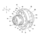
- FIG. 7 is a perspective view of the fan assembly 10 in which the motor 11 and the fan 16 are attached to the motor holder 30 of FIG.
- the motor 11 was inserted into the inner cylinder portion 32 of the motor holder 30 from the front side and screwed with screws 44 (see FIG. 3), and then the fan 16 was fixed to the rotating shaft 11a of the motor 11. It is a thing. Further, convex portions or concave portions (not visible in the drawing) are formed at four locations on the outer peripheral surface of the outer cylinder portion 36 of the motor holder 30, and an elastic body 48 is attached to each of them.
- the damper 28 is mounted on the bearing holder 15b (see FIG. 3) on the rear side of the motor 11.
- the damper 28 is manufactured by integrally molding synthetic resin or rubber, and is formed in a cup shape so as to cover the outer peripheral surface of the bearing holder 15b.
- the damper 28 is formed with a plurality of hollow portions in order to suppress the vibration of the bearing holder 15b in the radial direction. What shape the damper 28 has and what kind of vibration damping characteristics are provided. Is arbitrary.
- the motor holder 30 has a triple cylindrical portion of an inner cylinder portion 32, an inner cylinder portion 34, and an outer cylinder portion 36 arranged concentrically.
- the inner cylinder portion 32 forms the motor accommodating portion, and the inner peripheral surface of the inner cylinder portion 32 comes into contact with the outer peripheral surface of the casing of the motor 11.
- Between the inner cylinder portion 34 and the outer cylinder portion 36 there is a portion that serves as a main passage for the air discharged from the fan 16, and a second stationary blade 35 extending diagonally in the circumferential direction is formed there.
- Seven second stationary blades 35 are formed at equal intervals in the circumferential direction, and the space between them is the opening 39b.
- Eight radial ribs 33 extending in the radial direction and the axial direction are formed between the inner cylinder portion 32 and the middle cylinder portion 34.
- the space between the eight radial ribs 33 is an opening 39a from the fan 16 side to the rear side space of the motor 11, but a part of the air flow discharged from the fan 16 passes through the opening 39b. Flows from the rear to the front of the motor holder 30.
- FIG. 8 is a side view of the assembly (fan assembly 10) of FIG. This state indicates a state in which the elastic body 48 is not attached.
- the inner cylinder portion 32 is the main component of the motor accommodating portion, and the rear side of the inner cylinder portion 32 is the rear wall portion 31.
- An opening 31a (described later in FIG. 9) is formed in the rear wall portion 31, and the bearing holder 15a of the motor 11 projects rearward from the opening 31a.
- Electrodes 12a and 12b for supplying power to the motor 11 are formed at two locations on the rear side of the motor 11. Lead wires (not shown) are connected to the electrodes 12a and 12b, and DC power is supplied to the motor 11.
- Convex portions 36a for fitting into the concave portions of the elastic body 48 are formed on the upper and lower sides of the outer cylinder portion 36.
- recesses 36b are formed on the left side and the right side of the outer cylinder portion 36 (the right side cannot be seen in the drawing) so that the elastic body 48 having a substantially rectangular parallelepiped outer shape is buried more than half in the radial direction.
- the elastic body 48 mounted on the concave portion 36b and the elastic body 48 mounted on the convex portion 36a are the same component, but are mounted in opposite directions such as radial outward and inward.
- the shape and mounting direction of the elastic body 48, and the position and number of the concave portions 36b and the convex portions 36a are arbitrary, and other known mounting methods and cushioning mechanisms may be used.
- the outer surface of the casing of approximately half of the rear side of the motor 11 alone (the front half in the direction reference of the blower 1) is exposed in the air passage as shown as the motor exposed portion 38. Further, the motor 11 has a cooling fan 14 inside, air is sucked by the cooling fan 14 from the suction hole 15c (see FIG. 3) on the rear side, and the cooling fan 14 is radially outward through the opening 13 to the outside. Is discharged to. Assuming that the diameter of the motor is D m , the diameter D 2 of the inner cylinder portion 32 is slightly larger than the diameter D m of the motor. Specifically, the diameter D 2 is the size obtained by adding twice the plate thickness of the inner cylinder portion 32 and the gap required for mounting to the diameter D m of the motor.
- the diameter D 1 of the outer cylinder portion 36 of the motor holder 30 is configured to be sufficiently larger than the diameter D 2.
- the diameter D 1 should be about 1.5 to 3 times the diameter D 2 , and here it is approximately twice.
- the axial length L 2 of the outer cylinder portion 36 of the motor holder 30 is shorter than the axial length L 1 of the inner cylinder portion 32.
- FIG. 9 is a perspective view of the motor holder 30 alone of FIG. From FIG. 9, the sizes of the inner cylinder portion 32, the middle cylinder portion 34, and the outer cylinder portion 36 of the motor holder 30, and the positional relationship between the radial ribs 33 connecting them and the second stationary blade 35 can be understood. Let's go.
- the rear surface side of the inner cylinder portion 32 is closed by the rear wall portion 31 extending in the radial direction.
- An opening 31a for passing the bearing holder 15a (see FIG. 8) of the motor 11 is formed in the central axis of the rear wall portion 31. Further, two screw holes 31b are formed on the outer side in the radial direction from the opening 31a.
- the lengths of the middle cylinder portion 34 and the outer cylinder portion 36 in the axial direction are the same.
- Eight radial ribs 33 are arranged at equal intervals in the circumferential direction, and seven second stationary blades 35 are arranged at equal intervals in the circumferential direction.
- the outer cylinder portion 36, the middle cylinder portion 34, the inner cylinder portion 32, the second stationary blade 35, and the radial rib 33 form a second rectifying portion.
- the radial rib 33 is an example of the first rib
- the second stationary blade 35 is an example of the second rib.
- the second stationary blade 35 is a fin formed so that the position of the axis A1 changes in the circumferential direction, is arranged diagonally with respect to the radial rib 33, and is swiveled from the rear side by the fan 16 to the front. Guide the air discharged to the side.
- the position of the second stationary blade 35 in the axis A1 direction becomes forward as it goes in the circumferential direction from the connecting portion of the flat surface portion 35a orthogonal to the axis line A1 and in the same direction as the rotation direction of the fan 16. It is formed by the curved portion 35b.
- the purpose of installing the second stationary blade 35 is to smoothly guide the air discharged from the fan 16 to the front side.
- the second stationary blade 35 is a flat surface portion. It may be realized not only by the 35a and the curved portion 35b but also by other shapes. There is an opening 39b that serves as an air passage between the adjacent second stationary blade 35, and air flows in the direction of arrow F2.
- FIG. 10 is a cross-sectional view of a portion AA of FIG.
- the motor holder 30 is sandwiched between the left and right portions of the left-right split type housing 2. Therefore, the outer cylinder portion 36 of the motor holder 30 has a structure that is in contact with the inner wall of the fan case portion 3 or is in contact with the inner wall via an elastic body. Seven second stationary blades 35 are formed between the outer side of the inner cylinder portion 34 and the inner peripheral side of the outer cylinder portion 36 when viewed in the radial direction, and the space between the adjacent second stationary blades 35 is air. It becomes a flowing opening 39b.
- the second stationary blade 35 not only serves as a guide plate for guiding the air flow in a predetermined direction, but also functions as a frame for connecting the outer side of the inner cylinder portion 34 and the inner peripheral side of the outer cylinder portion 36. Since the space between the outside of the inner cylinder portion 32 and the inner cylinder portion 34 is not the main space through which air flows, the radial rib as a skeleton for firmly holding the accommodating portion (inner cylinder portion 32) of the motor 11 in the motor holder 30. 33 is provided.
- the radial ribs 33 have a planar shape extending in the radial direction and the axial direction, and eight ribs 33 are formed at equal intervals in the circumferential direction.
- the diameter of the inner cylinder portion 34 is reduced to make the second
- the stationary blade 35 of the above may be extended in the radial direction to increase the radial size of the opening 39b.
- the swirling component of the air flow discharged from the fan 16 is attenuated.
- the air flow in the fan case portion 3 can be made smooth, and the blowing performance of the blower 1 can be improved.
- the second stationary blade 35 is formed on the motor holder 30, it is possible to reduce the turbulence of the wind discharged from the fan 16.
- the second stationary blade 35 is integrally formed with the motor holder 30, even if the motor 11 to be used is changed to add product variations, it is only necessary to change the shape of the motor holder 30. The cost at the time of design change can be reduced.
- the present invention has been described above based on the examples, the present invention is not limited to the above-mentioned examples, and various modifications can be made without departing from the spirit of the present invention.
- a blower is described using a blower, but a filter type or cyclone type cleaner is also a kind of blower, and the present invention can be applied to the housing configuration thereof. In that case, it is preferable to provide the first stationary blade portion on the inner wall portion on the downstream side discharged from the fan.
- F 5 ... The air rectified by the first stationary blade is guided to the inside of the motor 11 by the first guide portion, L ... Motor axial length, L 1 ... Axial length of motor housing, L 2 ... Axial length of outer cylinder, D 1 ... Motor holder diameter, D 2 ... Motor housing diameter, D m ... Motor diameter
Landscapes
- Engineering & Computer Science (AREA)
- Mechanical Engineering (AREA)
- General Engineering & Computer Science (AREA)
- Physics & Mathematics (AREA)
- Thermal Sciences (AREA)
- Life Sciences & Earth Sciences (AREA)
- Environmental Sciences (AREA)
- Structures Of Non-Positive Displacement Pumps (AREA)
Priority Applications (5)
| Application Number | Priority Date | Filing Date | Title |
|---|---|---|---|
| DE112020003375.9T DE112020003375T5 (de) | 2019-08-29 | 2020-07-31 | Gebläse |
| US17/635,365 US11953016B2 (en) | 2019-08-29 | 2020-07-31 | Blower |
| CN202080055232.0A CN114174685A (zh) | 2019-08-29 | 2020-07-31 | 送风机 |
| JP2021542675A JP7424382B2 (ja) | 2019-08-29 | 2020-07-31 | 送風機 |
| JP2024005038A JP2024041943A (ja) | 2019-08-29 | 2024-01-17 | 送風機 |
Applications Claiming Priority (2)
| Application Number | Priority Date | Filing Date | Title |
|---|---|---|---|
| JP2019-156572 | 2019-08-29 | ||
| JP2019156572 | 2019-08-29 |
Publications (1)
| Publication Number | Publication Date |
|---|---|
| WO2021039291A1 true WO2021039291A1 (ja) | 2021-03-04 |
Family
ID=74684700
Family Applications (1)
| Application Number | Title | Priority Date | Filing Date |
|---|---|---|---|
| PCT/JP2020/029531 WO2021039291A1 (ja) | 2019-08-29 | 2020-07-31 | 送風機 |
Country Status (5)
| Country | Link |
|---|---|
| US (1) | US11953016B2 (zh) |
| JP (2) | JP7424382B2 (zh) |
| CN (1) | CN114174685A (zh) |
| DE (1) | DE112020003375T5 (zh) |
| WO (1) | WO2021039291A1 (zh) |
Cited By (1)
| Publication number | Priority date | Publication date | Assignee | Title |
|---|---|---|---|---|
| DE202023100742U1 (de) | 2022-03-04 | 2023-03-20 | Koki Holdings Co., Ltd. | Arbeitsmaschine |
Families Citing this family (2)
| Publication number | Priority date | Publication date | Assignee | Title |
|---|---|---|---|---|
| JP2021065463A (ja) * | 2019-10-24 | 2021-04-30 | 株式会社マキタ | 集塵機 |
| USD1011661S1 (en) * | 2023-06-15 | 2024-01-16 | Ningbo Winbay Technology Co., Ltd. | Leaf blower |
Citations (7)
| Publication number | Priority date | Publication date | Assignee | Title |
|---|---|---|---|---|
| JPS5495001A (en) * | 1978-01-10 | 1979-07-27 | Schick Inc | Hair arranging instrument and its axial blower device |
| JPS56129880U (zh) * | 1980-03-05 | 1981-10-02 | ||
| JPH0222051U (zh) * | 1988-07-29 | 1990-02-14 | ||
| JPH03501814A (ja) * | 1987-11-12 | 1991-04-25 | ブラック アンド デッカー インコーポレイティド | 携帯用送風機 |
| JP3064973U (ja) * | 1999-06-17 | 2000-01-28 | 株式会社バリテック新潟 | 送風機 |
| JP2014137030A (ja) * | 2013-01-17 | 2014-07-28 | Hitachi Koki Co Ltd | 携帯用ブロワ |
| JP2016078005A (ja) * | 2014-10-21 | 2016-05-16 | 株式会社マキタ | 送風作業機 |
Family Cites Families (10)
| Publication number | Priority date | Publication date | Assignee | Title |
|---|---|---|---|---|
| JPS56129880A (en) | 1980-03-15 | 1981-10-12 | Iruma Seiki Kk | Movement fastening mechanism combined with waterproofing for portable watch |
| US4945604A (en) * | 1987-11-12 | 1990-08-07 | Black & Decker Inc. | Portable blower |
| JP2739153B2 (ja) | 1988-04-30 | 1998-04-08 | ニチバン株式会社 | シーラー材およびシーラー材の施工方法 |
| JP3913334B2 (ja) | 1996-11-20 | 2007-05-09 | 三菱電機株式会社 | 換気送風装置および換気送風システム |
| US6302640B1 (en) * | 1999-11-10 | 2001-10-16 | Alliedsignal Inc. | Axial fan skip-stall |
| FR2973815B1 (fr) * | 2011-04-07 | 2014-08-29 | Pellenc Sa | Souffleur electroportatif autonome a vitesse de sortie d'air modulable |
| JP5983929B2 (ja) * | 2012-08-20 | 2016-09-06 | 日立工機株式会社 | 携帯用ブロワ |
| DE112014006478T5 (de) * | 2014-03-17 | 2016-12-29 | Husqvarna Ab | Motorgeräte-Kühlsystem |
| JP2016044586A (ja) * | 2014-08-22 | 2016-04-04 | 日立アプライアンス株式会社 | 空気調和機の室外ユニット |
| CN105747989B (zh) | 2015-01-06 | 2020-06-26 | 创科实业有限公司 | 轴流风机吸尘器 |
-
2020
- 2020-07-31 DE DE112020003375.9T patent/DE112020003375T5/de active Pending
- 2020-07-31 WO PCT/JP2020/029531 patent/WO2021039291A1/ja active Application Filing
- 2020-07-31 US US17/635,365 patent/US11953016B2/en active Active
- 2020-07-31 CN CN202080055232.0A patent/CN114174685A/zh active Pending
- 2020-07-31 JP JP2021542675A patent/JP7424382B2/ja active Active
-
2024
- 2024-01-17 JP JP2024005038A patent/JP2024041943A/ja active Pending
Patent Citations (7)
| Publication number | Priority date | Publication date | Assignee | Title |
|---|---|---|---|---|
| JPS5495001A (en) * | 1978-01-10 | 1979-07-27 | Schick Inc | Hair arranging instrument and its axial blower device |
| JPS56129880U (zh) * | 1980-03-05 | 1981-10-02 | ||
| JPH03501814A (ja) * | 1987-11-12 | 1991-04-25 | ブラック アンド デッカー インコーポレイティド | 携帯用送風機 |
| JPH0222051U (zh) * | 1988-07-29 | 1990-02-14 | ||
| JP3064973U (ja) * | 1999-06-17 | 2000-01-28 | 株式会社バリテック新潟 | 送風機 |
| JP2014137030A (ja) * | 2013-01-17 | 2014-07-28 | Hitachi Koki Co Ltd | 携帯用ブロワ |
| JP2016078005A (ja) * | 2014-10-21 | 2016-05-16 | 株式会社マキタ | 送風作業機 |
Cited By (1)
| Publication number | Priority date | Publication date | Assignee | Title |
|---|---|---|---|---|
| DE202023100742U1 (de) | 2022-03-04 | 2023-03-20 | Koki Holdings Co., Ltd. | Arbeitsmaschine |
Also Published As
| Publication number | Publication date |
|---|---|
| CN114174685A (zh) | 2022-03-11 |
| JP2024041943A (ja) | 2024-03-27 |
| JP7424382B2 (ja) | 2024-01-30 |
| JPWO2021039291A1 (zh) | 2021-03-04 |
| DE112020003375T5 (de) | 2022-06-23 |
| US20220341432A1 (en) | 2022-10-27 |
| US11953016B2 (en) | 2024-04-09 |
Similar Documents
| Publication | Publication Date | Title |
|---|---|---|
| WO2021039291A1 (ja) | 送風機 | |
| EP3179895B1 (en) | Vacuum cleaner | |
| CA2828567C (en) | Handheld blower | |
| JP5983929B2 (ja) | 携帯用ブロワ | |
| KR20200050928A (ko) | 휴대용 공기정화기 | |
| US9850915B2 (en) | Power tool | |
| JP7452601B2 (ja) | クリーナ | |
| JPWO2021039291A5 (zh) | ||
| JP5823192B2 (ja) | 動力工具 | |
| JP7102277B2 (ja) | クリーナ | |
| JP5039575B2 (ja) | 電動工具 | |
| US11744419B2 (en) | Cleaner | |
| JP5815310B2 (ja) | 動力工具 | |
| JP4851801B2 (ja) | 電動送風機および電気掃除機 | |
| CN112081763B (zh) | 鼓风机 | |
| KR20230116804A (ko) | 진공 청소기 | |
| JP2020193602A (ja) | 送風装置、および掃除機 | |
| US20230313805A1 (en) | Blower | |
| JP7255156B2 (ja) | クリーナ | |
| JP2020204173A (ja) | バッテリパックを電源とする作業機 | |
| JP2021092162A (ja) | 送風機 |
Legal Events
| Date | Code | Title | Description |
|---|---|---|---|
| 121 | Ep: the epo has been informed by wipo that ep was designated in this application |
Ref document number: 20856969 Country of ref document: EP Kind code of ref document: A1 |
|
| ENP | Entry into the national phase |
Ref document number: 2021542675 Country of ref document: JP Kind code of ref document: A |
|
| 122 | Ep: pct application non-entry in european phase |
Ref document number: 20856969 Country of ref document: EP Kind code of ref document: A1 |