WO2021031541A1 - Highly integrated analyte detection device - Google Patents
Highly integrated analyte detection device Download PDFInfo
- Publication number
- WO2021031541A1 WO2021031541A1 PCT/CN2020/075966 CN2020075966W WO2021031541A1 WO 2021031541 A1 WO2021031541 A1 WO 2021031541A1 CN 2020075966 W CN2020075966 W CN 2020075966W WO 2021031541 A1 WO2021031541 A1 WO 2021031541A1
- Authority
- WO
- WIPO (PCT)
- Prior art keywords
- electrical connection
- areas
- connection areas
- sensor
- detection system
- Prior art date
Links
- 238000001514 detection method Methods 0.000 title claims abstract description 66
- 239000012491 analyte Substances 0.000 title claims abstract description 42
- 238000009413 insulation Methods 0.000 claims description 22
- 238000007789 sealing Methods 0.000 claims description 11
- 239000002184 metal Substances 0.000 claims description 5
- 230000002708 enhancing effect Effects 0.000 abstract description 6
- WQZGKKKJIJFFOK-GASJEMHNSA-N Glucose Natural products OC[C@H]1OC(O)[C@H](O)[C@@H](O)[C@@H]1O WQZGKKKJIJFFOK-GASJEMHNSA-N 0.000 description 6
- 239000008103 glucose Substances 0.000 description 6
- NOESYZHRGYRDHS-UHFFFAOYSA-N insulin Chemical compound N1C(=O)C(NC(=O)C(CCC(N)=O)NC(=O)C(CCC(O)=O)NC(=O)C(C(C)C)NC(=O)C(NC(=O)CN)C(C)CC)CSSCC(C(NC(CO)C(=O)NC(CC(C)C)C(=O)NC(CC=2C=CC(O)=CC=2)C(=O)NC(CCC(N)=O)C(=O)NC(CC(C)C)C(=O)NC(CCC(O)=O)C(=O)NC(CC(N)=O)C(=O)NC(CC=2C=CC(O)=CC=2)C(=O)NC(CSSCC(NC(=O)C(C(C)C)NC(=O)C(CC(C)C)NC(=O)C(CC=2C=CC(O)=CC=2)NC(=O)C(CC(C)C)NC(=O)C(C)NC(=O)C(CCC(O)=O)NC(=O)C(C(C)C)NC(=O)C(CC(C)C)NC(=O)C(CC=2NC=NC=2)NC(=O)C(CO)NC(=O)CNC2=O)C(=O)NCC(=O)NC(CCC(O)=O)C(=O)NC(CCCNC(N)=N)C(=O)NCC(=O)NC(CC=3C=CC=CC=3)C(=O)NC(CC=3C=CC=CC=3)C(=O)NC(CC=3C=CC(O)=CC=3)C(=O)NC(C(C)O)C(=O)N3C(CCC3)C(=O)NC(CCCCN)C(=O)NC(C)C(O)=O)C(=O)NC(CC(N)=O)C(O)=O)=O)NC(=O)C(C(C)CC)NC(=O)C(CO)NC(=O)C(C(C)O)NC(=O)C1CSSCC2NC(=O)C(CC(C)C)NC(=O)C(NC(=O)C(CCC(N)=O)NC(=O)C(CC(N)=O)NC(=O)C(NC(=O)C(N)CC=1C=CC=CC=1)C(C)C)CC1=CN=CN1 NOESYZHRGYRDHS-UHFFFAOYSA-N 0.000 description 6
- 238000000034 method Methods 0.000 description 6
- 239000008280 blood Substances 0.000 description 5
- 210000004369 blood Anatomy 0.000 description 5
- 206010012601 diabetes mellitus Diseases 0.000 description 5
- 210000001124 body fluid Anatomy 0.000 description 4
- 239000010839 body fluid Substances 0.000 description 4
- 230000005611 electricity Effects 0.000 description 4
- 102000004877 Insulin Human genes 0.000 description 3
- 108090001061 Insulin Proteins 0.000 description 3
- 238000013461 design Methods 0.000 description 3
- 229940125396 insulin Drugs 0.000 description 3
- 210000000496 pancreas Anatomy 0.000 description 3
- 230000002159 abnormal effect Effects 0.000 description 2
- 238000010586 diagram Methods 0.000 description 2
- 230000000694 effects Effects 0.000 description 2
- 239000012530 fluid Substances 0.000 description 2
- 238000009434 installation Methods 0.000 description 2
- 206010033675 panniculitis Diseases 0.000 description 2
- 210000004304 subcutaneous tissue Anatomy 0.000 description 2
- 102000051325 Glucagon Human genes 0.000 description 1
- 108060003199 Glucagon Proteins 0.000 description 1
- 238000011161 development Methods 0.000 description 1
- 201000010099 disease Diseases 0.000 description 1
- 208000016097 disease of metabolism Diseases 0.000 description 1
- 208000037265 diseases, disorders, signs and symptoms Diseases 0.000 description 1
- 238000005516 engineering process Methods 0.000 description 1
- 230000006870 function Effects 0.000 description 1
- 230000014509 gene expression Effects 0.000 description 1
- MASNOZXLGMXCHN-ZLPAWPGGSA-N glucagon Chemical compound C([C@@H](C(=O)N[C@H](C(=O)N[C@@H](CCC(N)=O)C(=O)N[C@@H](CC=1C2=CC=CC=C2NC=1)C(=O)N[C@@H](CC(C)C)C(=O)N[C@@H](CCSC)C(=O)N[C@@H](CC(N)=O)C(=O)N[C@@H]([C@@H](C)O)C(O)=O)C(C)C)NC(=O)[C@H](CC(O)=O)NC(=O)[C@H](CCC(N)=O)NC(=O)[C@H](C)NC(=O)[C@H](CCCNC(N)=N)NC(=O)[C@H](CCCNC(N)=N)NC(=O)[C@H](CO)NC(=O)[C@H](CC(O)=O)NC(=O)[C@H](CC(C)C)NC(=O)[C@H](CC=1C=CC(O)=CC=1)NC(=O)[C@H](CCCCN)NC(=O)[C@H](CO)NC(=O)[C@H](CC=1C=CC(O)=CC=1)NC(=O)[C@H](CC(O)=O)NC(=O)[C@H](CO)NC(=O)[C@@H](NC(=O)[C@H](CC=1C=CC=CC=1)NC(=O)[C@@H](NC(=O)CNC(=O)[C@H](CCC(N)=O)NC(=O)[C@H](CO)NC(=O)[C@@H](N)CC=1NC=NC=1)[C@@H](C)O)[C@@H](C)O)C1=CC=CC=C1 MASNOZXLGMXCHN-ZLPAWPGGSA-N 0.000 description 1
- 229960004666 glucagon Drugs 0.000 description 1
- 208000030159 metabolic disease Diseases 0.000 description 1
- 238000012544 monitoring process Methods 0.000 description 1
- 230000004203 pancreatic function Effects 0.000 description 1
- 230000000149 penetrating effect Effects 0.000 description 1
- 238000011160 research Methods 0.000 description 1
- 239000000523 sample Substances 0.000 description 1
- 230000000087 stabilizing effect Effects 0.000 description 1
- 238000012360 testing method Methods 0.000 description 1
Images


Classifications
-
- A—HUMAN NECESSITIES
- A61—MEDICAL OR VETERINARY SCIENCE; HYGIENE
- A61M—DEVICES FOR INTRODUCING MEDIA INTO, OR ONTO, THE BODY; DEVICES FOR TRANSDUCING BODY MEDIA OR FOR TAKING MEDIA FROM THE BODY; DEVICES FOR PRODUCING OR ENDING SLEEP OR STUPOR
- A61M5/00—Devices for bringing media into the body in a subcutaneous, intra-vascular or intramuscular way; Accessories therefor, e.g. filling or cleaning devices, arm-rests
- A61M5/14—Infusion devices, e.g. infusing by gravity; Blood infusion; Accessories therefor
- A61M5/142—Pressure infusion, e.g. using pumps
- A61M5/14244—Pressure infusion, e.g. using pumps adapted to be carried by the patient, e.g. portable on the body
- A61M5/14248—Pressure infusion, e.g. using pumps adapted to be carried by the patient, e.g. portable on the body of the skin patch type
-
- A—HUMAN NECESSITIES
- A61—MEDICAL OR VETERINARY SCIENCE; HYGIENE
- A61B—DIAGNOSIS; SURGERY; IDENTIFICATION
- A61B5/00—Measuring for diagnostic purposes; Identification of persons
- A61B5/145—Measuring characteristics of blood in vivo, e.g. gas concentration, pH value; Measuring characteristics of body fluids or tissues, e.g. interstitial fluid, cerebral tissue
- A61B5/14532—Measuring characteristics of blood in vivo, e.g. gas concentration, pH value; Measuring characteristics of body fluids or tissues, e.g. interstitial fluid, cerebral tissue for measuring glucose, e.g. by tissue impedance measurement
-
- A—HUMAN NECESSITIES
- A61—MEDICAL OR VETERINARY SCIENCE; HYGIENE
- A61B—DIAGNOSIS; SURGERY; IDENTIFICATION
- A61B5/00—Measuring for diagnostic purposes; Identification of persons
- A61B5/0002—Remote monitoring of patients using telemetry, e.g. transmission of vital signals via a communication network
- A61B5/0015—Remote monitoring of patients using telemetry, e.g. transmission of vital signals via a communication network characterised by features of the telemetry system
- A61B5/002—Monitoring the patient using a local or closed circuit, e.g. in a room or building
-
- A—HUMAN NECESSITIES
- A61—MEDICAL OR VETERINARY SCIENCE; HYGIENE
- A61B—DIAGNOSIS; SURGERY; IDENTIFICATION
- A61B5/00—Measuring for diagnostic purposes; Identification of persons
- A61B5/145—Measuring characteristics of blood in vivo, e.g. gas concentration, pH value; Measuring characteristics of body fluids or tissues, e.g. interstitial fluid, cerebral tissue
- A61B5/14503—Measuring characteristics of blood in vivo, e.g. gas concentration, pH value; Measuring characteristics of body fluids or tissues, e.g. interstitial fluid, cerebral tissue invasive, e.g. introduced into the body by a catheter or needle or using implanted sensors
-
- A—HUMAN NECESSITIES
- A61—MEDICAL OR VETERINARY SCIENCE; HYGIENE
- A61B—DIAGNOSIS; SURGERY; IDENTIFICATION
- A61B5/00—Measuring for diagnostic purposes; Identification of persons
- A61B5/145—Measuring characteristics of blood in vivo, e.g. gas concentration, pH value; Measuring characteristics of body fluids or tissues, e.g. interstitial fluid, cerebral tissue
- A61B5/14507—Measuring characteristics of blood in vivo, e.g. gas concentration, pH value; Measuring characteristics of body fluids or tissues, e.g. interstitial fluid, cerebral tissue specially adapted for measuring characteristics of body fluids other than blood
- A61B5/1451—Measuring characteristics of blood in vivo, e.g. gas concentration, pH value; Measuring characteristics of body fluids or tissues, e.g. interstitial fluid, cerebral tissue specially adapted for measuring characteristics of body fluids other than blood for interstitial fluid
-
- A—HUMAN NECESSITIES
- A61—MEDICAL OR VETERINARY SCIENCE; HYGIENE
- A61B—DIAGNOSIS; SURGERY; IDENTIFICATION
- A61B5/00—Measuring for diagnostic purposes; Identification of persons
- A61B5/145—Measuring characteristics of blood in vivo, e.g. gas concentration, pH value; Measuring characteristics of body fluids or tissues, e.g. interstitial fluid, cerebral tissue
- A61B5/14546—Measuring characteristics of blood in vivo, e.g. gas concentration, pH value; Measuring characteristics of body fluids or tissues, e.g. interstitial fluid, cerebral tissue for measuring analytes not otherwise provided for, e.g. ions, cytochromes
-
- A—HUMAN NECESSITIES
- A61—MEDICAL OR VETERINARY SCIENCE; HYGIENE
- A61B—DIAGNOSIS; SURGERY; IDENTIFICATION
- A61B5/00—Measuring for diagnostic purposes; Identification of persons
- A61B5/145—Measuring characteristics of blood in vivo, e.g. gas concentration, pH value; Measuring characteristics of body fluids or tissues, e.g. interstitial fluid, cerebral tissue
- A61B5/1468—Measuring characteristics of blood in vivo, e.g. gas concentration, pH value; Measuring characteristics of body fluids or tissues, e.g. interstitial fluid, cerebral tissue using chemical or electrochemical methods, e.g. by polarographic means
- A61B5/1473—Measuring characteristics of blood in vivo, e.g. gas concentration, pH value; Measuring characteristics of body fluids or tissues, e.g. interstitial fluid, cerebral tissue using chemical or electrochemical methods, e.g. by polarographic means invasive, e.g. introduced into the body by a catheter
-
- A—HUMAN NECESSITIES
- A61—MEDICAL OR VETERINARY SCIENCE; HYGIENE
- A61B—DIAGNOSIS; SURGERY; IDENTIFICATION
- A61B5/00—Measuring for diagnostic purposes; Identification of persons
- A61B5/68—Arrangements of detecting, measuring or recording means, e.g. sensors, in relation to patient
- A61B5/6801—Arrangements of detecting, measuring or recording means, e.g. sensors, in relation to patient specially adapted to be attached to or worn on the body surface
- A61B5/683—Means for maintaining contact with the body
- A61B5/6838—Clamps or clips
-
- A—HUMAN NECESSITIES
- A61—MEDICAL OR VETERINARY SCIENCE; HYGIENE
- A61B—DIAGNOSIS; SURGERY; IDENTIFICATION
- A61B5/00—Measuring for diagnostic purposes; Identification of persons
- A61B5/68—Arrangements of detecting, measuring or recording means, e.g. sensors, in relation to patient
- A61B5/6846—Arrangements of detecting, measuring or recording means, e.g. sensors, in relation to patient specially adapted to be brought in contact with an internal body part, i.e. invasive
- A61B5/6847—Arrangements of detecting, measuring or recording means, e.g. sensors, in relation to patient specially adapted to be brought in contact with an internal body part, i.e. invasive mounted on an invasive device
- A61B5/6848—Needles
-
- B—PERFORMING OPERATIONS; TRANSPORTING
- B01—PHYSICAL OR CHEMICAL PROCESSES OR APPARATUS IN GENERAL
- B01L—CHEMICAL OR PHYSICAL LABORATORY APPARATUS FOR GENERAL USE
- B01L3/00—Containers or dishes for laboratory use, e.g. laboratory glassware; Droppers
- B01L3/50—Containers for the purpose of retaining a material to be analysed, e.g. test tubes
- B01L3/502—Containers for the purpose of retaining a material to be analysed, e.g. test tubes with fluid transport, e.g. in multi-compartment structures
- B01L3/5027—Containers for the purpose of retaining a material to be analysed, e.g. test tubes with fluid transport, e.g. in multi-compartment structures by integrated microfluidic structures, i.e. dimensions of channels and chambers are such that surface tension forces are important, e.g. lab-on-a-chip
- B01L3/502715—Containers for the purpose of retaining a material to be analysed, e.g. test tubes with fluid transport, e.g. in multi-compartment structures by integrated microfluidic structures, i.e. dimensions of channels and chambers are such that surface tension forces are important, e.g. lab-on-a-chip characterised by interfacing components, e.g. fluidic, electrical, optical or mechanical interfaces
-
- B—PERFORMING OPERATIONS; TRANSPORTING
- B01—PHYSICAL OR CHEMICAL PROCESSES OR APPARATUS IN GENERAL
- B01L—CHEMICAL OR PHYSICAL LABORATORY APPARATUS FOR GENERAL USE
- B01L3/00—Containers or dishes for laboratory use, e.g. laboratory glassware; Droppers
- B01L3/50—Containers for the purpose of retaining a material to be analysed, e.g. test tubes
- B01L3/505—Containers for the purpose of retaining a material to be analysed, e.g. test tubes flexible containers not provided for above
-
- B—PERFORMING OPERATIONS; TRANSPORTING
- B01—PHYSICAL OR CHEMICAL PROCESSES OR APPARATUS IN GENERAL
- B01L—CHEMICAL OR PHYSICAL LABORATORY APPARATUS FOR GENERAL USE
- B01L3/00—Containers or dishes for laboratory use, e.g. laboratory glassware; Droppers
- B01L3/50—Containers for the purpose of retaining a material to be analysed, e.g. test tubes
- B01L3/508—Containers for the purpose of retaining a material to be analysed, e.g. test tubes rigid containers not provided for above
-
- A—HUMAN NECESSITIES
- A61—MEDICAL OR VETERINARY SCIENCE; HYGIENE
- A61B—DIAGNOSIS; SURGERY; IDENTIFICATION
- A61B2560/00—Constructional details of operational features of apparatus; Accessories for medical measuring apparatus
- A61B2560/02—Operational features
- A61B2560/0204—Operational features of power management
- A61B2560/0214—Operational features of power management of power generation or supply
-
- A—HUMAN NECESSITIES
- A61—MEDICAL OR VETERINARY SCIENCE; HYGIENE
- A61B—DIAGNOSIS; SURGERY; IDENTIFICATION
- A61B2560/00—Constructional details of operational features of apparatus; Accessories for medical measuring apparatus
- A61B2560/04—Constructional details of apparatus
- A61B2560/0443—Modular apparatus
- A61B2560/045—Modular apparatus with a separable interface unit, e.g. for communication
-
- A—HUMAN NECESSITIES
- A61—MEDICAL OR VETERINARY SCIENCE; HYGIENE
- A61B—DIAGNOSIS; SURGERY; IDENTIFICATION
- A61B2560/00—Constructional details of operational features of apparatus; Accessories for medical measuring apparatus
- A61B2560/04—Constructional details of apparatus
- A61B2560/0462—Apparatus with built-in sensors
-
- A—HUMAN NECESSITIES
- A61—MEDICAL OR VETERINARY SCIENCE; HYGIENE
- A61B—DIAGNOSIS; SURGERY; IDENTIFICATION
- A61B2562/00—Details of sensors; Constructional details of sensor housings or probes; Accessories for sensors
- A61B2562/08—Sensors provided with means for identification, e.g. barcodes or memory chips
-
- A—HUMAN NECESSITIES
- A61—MEDICAL OR VETERINARY SCIENCE; HYGIENE
- A61B—DIAGNOSIS; SURGERY; IDENTIFICATION
- A61B2562/00—Details of sensors; Constructional details of sensor housings or probes; Accessories for sensors
- A61B2562/16—Details of sensor housings or probes; Details of structural supports for sensors
-
- A—HUMAN NECESSITIES
- A61—MEDICAL OR VETERINARY SCIENCE; HYGIENE
- A61B—DIAGNOSIS; SURGERY; IDENTIFICATION
- A61B2562/00—Details of sensors; Constructional details of sensor housings or probes; Accessories for sensors
- A61B2562/22—Arrangements of medical sensors with cables or leads; Connectors or couplings specifically adapted for medical sensors
- A61B2562/225—Connectors or couplings
- A61B2562/227—Sensors with electrical connectors
-
- A—HUMAN NECESSITIES
- A61—MEDICAL OR VETERINARY SCIENCE; HYGIENE
- A61M—DEVICES FOR INTRODUCING MEDIA INTO, OR ONTO, THE BODY; DEVICES FOR TRANSDUCING BODY MEDIA OR FOR TAKING MEDIA FROM THE BODY; DEVICES FOR PRODUCING OR ENDING SLEEP OR STUPOR
- A61M2205/00—General characteristics of the apparatus
- A61M2205/33—Controlling, regulating or measuring
-
- A—HUMAN NECESSITIES
- A61—MEDICAL OR VETERINARY SCIENCE; HYGIENE
- A61M—DEVICES FOR INTRODUCING MEDIA INTO, OR ONTO, THE BODY; DEVICES FOR TRANSDUCING BODY MEDIA OR FOR TAKING MEDIA FROM THE BODY; DEVICES FOR PRODUCING OR ENDING SLEEP OR STUPOR
- A61M2205/00—General characteristics of the apparatus
- A61M2205/50—General characteristics of the apparatus with microprocessors or computers
- A61M2205/502—User interfaces, e.g. screens or keyboards
-
- B—PERFORMING OPERATIONS; TRANSPORTING
- B01—PHYSICAL OR CHEMICAL PROCESSES OR APPARATUS IN GENERAL
- B01L—CHEMICAL OR PHYSICAL LABORATORY APPARATUS FOR GENERAL USE
- B01L2200/00—Solutions for specific problems relating to chemical or physical laboratory apparatus
- B01L2200/06—Fluid handling related problems
- B01L2200/0689—Sealing
-
- B—PERFORMING OPERATIONS; TRANSPORTING
- B01—PHYSICAL OR CHEMICAL PROCESSES OR APPARATUS IN GENERAL
- B01L—CHEMICAL OR PHYSICAL LABORATORY APPARATUS FOR GENERAL USE
- B01L2300/00—Additional constructional details
- B01L2300/02—Identification, exchange or storage of information
- B01L2300/023—Sending and receiving of information, e.g. using bluetooth
-
- B—PERFORMING OPERATIONS; TRANSPORTING
- B01—PHYSICAL OR CHEMICAL PROCESSES OR APPARATUS IN GENERAL
- B01L—CHEMICAL OR PHYSICAL LABORATORY APPARATUS FOR GENERAL USE
- B01L2300/00—Additional constructional details
- B01L2300/06—Auxiliary integrated devices, integrated components
- B01L2300/0609—Holders integrated in container to position an object
-
- B—PERFORMING OPERATIONS; TRANSPORTING
- B01—PHYSICAL OR CHEMICAL PROCESSES OR APPARATUS IN GENERAL
- B01L—CHEMICAL OR PHYSICAL LABORATORY APPARATUS FOR GENERAL USE
- B01L2300/00—Additional constructional details
- B01L2300/06—Auxiliary integrated devices, integrated components
- B01L2300/0627—Sensor or part of a sensor is integrated
- B01L2300/0645—Electrodes
-
- B—PERFORMING OPERATIONS; TRANSPORTING
- B01—PHYSICAL OR CHEMICAL PROCESSES OR APPARATUS IN GENERAL
- B01L—CHEMICAL OR PHYSICAL LABORATORY APPARATUS FOR GENERAL USE
- B01L2300/00—Additional constructional details
- B01L2300/06—Auxiliary integrated devices, integrated components
- B01L2300/0627—Sensor or part of a sensor is integrated
- B01L2300/0663—Whole sensors
-
- B—PERFORMING OPERATIONS; TRANSPORTING
- B01—PHYSICAL OR CHEMICAL PROCESSES OR APPARATUS IN GENERAL
- B01L—CHEMICAL OR PHYSICAL LABORATORY APPARATUS FOR GENERAL USE
- B01L2300/00—Additional constructional details
- B01L2300/12—Specific details about materials
- B01L2300/123—Flexible; Elastomeric
-
- B—PERFORMING OPERATIONS; TRANSPORTING
- B01—PHYSICAL OR CHEMICAL PROCESSES OR APPARATUS IN GENERAL
- B01L—CHEMICAL OR PHYSICAL LABORATORY APPARATUS FOR GENERAL USE
- B01L2400/00—Moving or stopping fluids
- B01L2400/06—Valves, specific forms thereof
- B01L2400/0677—Valves, specific forms thereof phase change valves; Meltable, freezing, dissolvable plugs; Destructible barriers
-
- Y—GENERAL TAGGING OF NEW TECHNOLOGICAL DEVELOPMENTS; GENERAL TAGGING OF CROSS-SECTIONAL TECHNOLOGIES SPANNING OVER SEVERAL SECTIONS OF THE IPC; TECHNICAL SUBJECTS COVERED BY FORMER USPC CROSS-REFERENCE ART COLLECTIONS [XRACs] AND DIGESTS
- Y02—TECHNOLOGIES OR APPLICATIONS FOR MITIGATION OR ADAPTATION AGAINST CLIMATE CHANGE
- Y02E—REDUCTION OF GREENHOUSE GAS [GHG] EMISSIONS, RELATED TO ENERGY GENERATION, TRANSMISSION OR DISTRIBUTION
- Y02E60/00—Enabling technologies; Technologies with a potential or indirect contribution to GHG emissions mitigation
- Y02E60/10—Energy storage using batteries
Definitions
- the present invention mainly relates to the field of medical device, and in particular, to a highly integrated analyte detection system.
- pancreas in a normal person can automatically monitor the amount of glucose in the blood and automatically secrete the required dosage of insulin/glucagon.
- the function of the pancreas is abnormal, and the pancreas cannot normally secrete required dosage of insulin. Therefore, diabetes is a metabolic disease caused by abnormal pancreatic function, which is also a lifelong disease.
- medical technology cannot cure diabetes, and it can only control the occurrence and development of diabetes and its complications by stabilizing blood glucose.
- CGM Continuous Glucose Monitoring
- the current detection device is not compact, resulting in thicker overall and larger volume, affecting the user's dressing, stretching, exercise and other daily activities, which can seriously worsen user experience. Also, detection can be easily interrupted with such a sensing device because a bulky device can get bumped or caught easily, which may lead to data loss and pose a potential safety hazard to the user.
- the embodiment of the invention discloses a highly integrated analyte detection system.
- the sensor has a shape of a polyline or an arc, which reduces the height of the sensor structure, making the overall structure of the detection system more compact, further, as a result, reducing the volume and enhancing the user experience.
- the invention discloses a highly integrated analyte detection system, including: a bottom case; a sensor structure, the sensor structure and the bottom case are fastened with each other, the sensor structure includes a sensor and a sensor base, the sensor includes a signal output end and a detection end, the output end has a shape of a polyline or an arc toward the top surface of the sensor base, and at least two first electrical connection areas insulated from each other are provided on the surface of the signal output end; and a transmitter, the transmitter and the bottom case are fastened with each other, and the transmitter is provided with the second electrical connection areas which are insulated from each other and correspond to the first electrical connection areas, each second electrical connection area is electrically connected to each corresponding first electrical connection area.
- the second electrical connection areas are metal contacts.
- the signal output end is a planar structure and is laid on the top of the sensor base.
- it further includes a sealing member, the sealing member is arranged around the position where the signal output end is electrically connected with the electrical connection area.
- a mounting hole is provided on the bottom board of the bottom case, the first fastener part is provided at the edge of the mounting hole, and the second fastener part is provided at the edge of the sensor base, the contour shapes of the edge of the sensor base and that of the mounting hole match each other, the first fastener part and the second fastener part are fastened with each other, the edge of the mounting hole and the edge of the sensor base are interlocked, and the sensor base is installed in the mounting hole.
- it further includes the first elastic conductive member disposed between the first electrical connection areas and the second electrical connection areas.
- the first elastic conductive member includes conductive areas and insulation areas, and the insulation area is spaced between two adjacent conductive areas, the conductive areas and the insulation areas expand across the first elastic conductive member in a vertical direction, respectively.
- the conductive areas and the insulation areas are separated from each other, the first electrical connection areas are electrically connected with the corresponding second electrical connection areas through the conductive areas, and the insulation area is disposed between two adjacent first electrical connection areas or two adjacent second electrical connection areas.
- the transmitter is provided with at least two third electrical connection areas, and the second elastic conductive member is disposed between the third electrical connection areas and the sensor base, after electrical connecting with the second elastic conductive member, the different third electrical connection areas are connected.
- the signal output end has a shape of a polyline or an arc toward the top surface of the sensor base, which can reduce the height of the sensor structure, so that no extra space is required in the transmitter to accommodate the structure protruding from the bottom board of the bottom case, making the overall structure of the detection system more compact, thinner and smaller and greatly enhancing the user experience.
- the second electrical connection areas are metal contacts. Metal contacts can reduce the electrical connection area and the volume of the analyte detection system.
- the signal output end is a planar structure and is laid on the top of the sensor base. Because the thickness of the sensor is extremely thin (at micron level) , the height of the sensor structure does not increase when the signal output end is laid on the top of the sensor base, which no extra space is required to accommodates the signal output end protruding from bottom base, ultimately reducing the thickness of the transmitter and the volume of the detection system.
- a mounting hole is provided on the bottom board of the bottom case, the first fastener part is provided at the edge of the mounting hole, and the second fastener part is provided at the edge of the sensor base. Setting the fastener part at the edge can finally reduce the height of the fastening position, making the internal structure more compact.
- the contour shape of the edge of the sensor base matches that of the mounting hole, the first fastener part and the second fastener part are fastened with each other, and the edge of the mounting hole and the edge of the sensor base are interlocked with each other.
- the interlocked edge of the mounting hole and the sensor base makes the sensor structure entirely embedded in the mounting hole, which further reduces the height of the top of the sensor structure and is conducive to reduce the volume of the detection system.
- the highly integrated analyte detection system further includes the first elastic conductive member disposed between the first electrical connection areas and the second electrical connection areas.
- the elastic conductive member can make a better electrical connect between the first electrical connection areas and the second electrical connection areas.
- the conductive areas and the insulation areas of the first elastic conductive member are separated from each other.
- the first electrical connection areas is electrically connected to the corresponding second electrical connection areas through the conductive areas, and the insulation area is set between the adjacent first electrical connection areas or the adjacent second electrical connection areas.
- FIG. 1 is a schematic perspective view of a bottom case according to an embodiment of the present invention
- FIG. 2a is a schematic perspective view of the sensor structure and the sealing member according to the embodiment of the present invention.
- FIG. 2b is a schematic perspective view of the sensor according to an embodiment of the present invention.
- FIG. 3 is a schematic perspective view of the transmitter according to an embodiment of the present invention.
- FIG. 4a is a schematic perspective view of the sensor structure according to an embodiment of the present invention.
- FIG. 4b and FIG. 4c are schematic diagrams of sensors and their adjacent structures of different embodiments obtained along the section line A-A' in FIG. 4a, respectively;
- FIG. 4d is a schematic cross-sectional structural view of the first elastic conductive member obtained along a section line B-B' in FIG. 4a;
- FIG. 4e is a schematic top view of the longitudinal section of FIG. 4d;
- FIG. 4f -FIG. 4h are top views of the first elastic conductive member according to different embodiments.
- FIG. 4i is a schematic structural view of a longitudinal section of the structure of FIG. 4h;
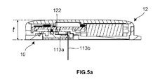
- FIG. 5a is a side view of a highly integrated analyte detection system after installation according to an embodiment of the present invention
- FIG. 5b is a schematic longitudinal cross-sectional structural view of the first electrical connection areas and the second electrical connection areas in FIG. 5a after being electrically connected;
- FIG. 5c is a longitudinal sectional structural view of the highly integrated analyte detection system of FIG. 5a.
- the prior art body fluid parameter detection device has a larger volume and is easy to get caught while being worn on the skin surface, which leads to poor user experiences and brings inconvenience to the patient's life.
- the reason for the above problem is that the height of the sensor structure protruding from the inner bottom surface of the bottom case in the prior detection device is large. Extra space is required along the thickness direction of the transmitter to accommodate the foresaid protruding portion, increasing the thickness of the transmitter.
- the present invention provides a highly integrated analyte detection device.
- the signal output end has a shape of a polyline or an arc toward the top surface of the sensor base, which can reduce the height of the sensor structure, so that no extra space is required in the transmitter to accommodate the structure protruding from the bottom board of the bottom case, making the overall structure of the detection system more compact, thinner and smaller and greatly enhancing the user experience.
- FIG. 1 is a schematic perspective view of a bottom case 10 according to an embodiment of the present invention.
- the bottom case 10 is used for mounting the sensor structure and the transmitter.
- the bottom board of the bottom case 10 is provided with a mounting hole 101 for mounting the sensor structure, while the fastener structure for fixing the transmitter is designed on the side wall of the bottom case 10.
- a first fastener part 102 is provided at the edge of the mounting hole 101.
- being provided at the “edge” means that the top of the first fastener part 102 is not higher than or slightly higher than the inner bottom surface of the bottom case 10.
- the embodiment of the present invention does not specifically limit the shape and type of the first fastener part 102 and the shape of the mounting hole 101, as long as the conditions for mounting the sensor structure can be satisfied.
- FIG. 2a is a schematic perspective view of the sensor structure 11 and the sealing member 130 according to the embodiment of the present invention.
- FIG. 2b is a schematic perspective view of the sensor 113 according to the embodiment of the present invention.
- the sensor structure 11 includes a sensor base 111 and a sensor 113.
- a second fastener part 112 is provided at the edge of the sensor base 111 for fastening with the first fastener part 102.
- the contour shape of the edge of the mounting hole 101 matches that of the sensor base 111. Therefore, when the sensor structure 11 and the bottom case 10 are fastened with each other, the edge of the mounting hole 101 and the edge of the sensor base 111 are interlocked with each other, and the sensor base 111 is installed in the mounting hole 101.
- the first fastener part 102 and the second fastener part 112 are both disposed at the edge, the position where these two fastener parts are fastened is not higher than the top of the sensor structure 11.
- Such a design reduces the height of the sensor structure 11, so that no extra space is required in the transmitter, which reduces the thickness of the transmitter and ultimately reduces the overall volume of the analyte detection system.
- the sensor 113 includes a signal output end 113a and a detection end 113b.
- the signal output end 113a needs to be electrically connected to the second electrical connection areas of the transmitter to output the detection signal to the transmitter.
- the detection end 113b is used to pierce subcutaneous tissue of a human body to detect body fluid analyte parameters.
- the signal output end 113a is embedded in the sensor base 111.
- the surface of the signal output end 113a is provided with the first electrical connection areas 116 which are insulated from each other.
- the surface of the sensor 113 is further provided with electrodes and electrode leads (not shown) for detecting parameters of the fluid analyte.
- the signals of the electrodes need to be derived through the first electrical connection areas 116.
- at least two detection electrodes are provided on the sensor 113, so in the present invention, at least two first electrical connection areas 116 are provided on the surface of the signal output end 113a to be electrically connected to different electrodes.
- there are three electrodes on the sensor 113 thus the number of the first electrical connection areas 116 is three.
- the sealing member 130 which has dust-proof feature, moisture-proof feature, water-proof feature and the like, is configured to seal the connection position between the signal output end 113a and the electrical connection areas.
- the sensor base 111 of the embodiment of the present invention is provided with a groove 131 in which the sealing member 130 is placed.
- the installed sealing member 130 surrounds the connection position between the signal output end 113a and the electrical connection areas to achieve sealing effect.
- the sealing member 130 may not be provided.
- the first elastic conductive member 114 and the second elastic conductive member 115 which are finally located between the transmitter and sensor structure 11, are further disposed on the top of the sensor base 111. In another embodiment of the present invention, only the first elastic conductive member 114 is disposed, which will be described in detail below.
- first elastic conductive member 114 and the second elastic conductive member 115 may not be provided, while the corresponding positions of the transmitter and the sensor structure are directly connected with each other.
- FIG. 3 is a schematic perspective view of the transmitter 12 according to the embodiment of the present invention.
- the transmitter 12 is provided with second electrical connection areas 122 which are insulated from each other.
- the second electrical connection areas 122 are exposed and protrude from the transmitter housing 121 to facilitate electrical connect with the corresponding first electrical connection areas 116.
- the second electrical connection areas 122 are metal contacts which are much smaller, making the internal structure of the analyte detection system much more compact and reducing the overall volume of the analyte detection system.
- the second electrical connection areas 122 may not protrude from the surface of the transmitter case 121.
- the transmitter 12 is further provided with at least two third electrical connection areas 123 which can be configured to activate the analyte detection system or used as an interface to charge the transmitter 12. And the third electrical connection areas 123 will electrically connect with the second elastic conductive member 115.
- the position and shape of the third electrical connection areas 123 and their position relationship with the second electrical connection areas 122 are not specifically limited.
- the third electrical connection areas 123 are not provided. Obviously, there is also no need to provide the second elastic conductive member 115 in the analyte detection system.
- FIG. 4a is a schematic perspective view of the sensor structure 11.
- FIG. 4b and FIG. 4c are schematic diagrams of sensors 113 and their adjacent structures of different embodiments obtained along the section line A-A' in FIG. 4a, respectively.
- FIG. 4d is a schematic cross-sectional structural view of the first elastic conductive member 114 obtained along a section line B-B' in FIG. 4a.
- FIG. 4e is a schematic top view of the longitudinal section of FIG. 4d.
- FIG. 4f -FIG. 4h are top views of the first elastic conductive member 114 according to different embodiments.
- FIG. 4i is a schematic structural view of a longitudinal section of the structure of FIG. 4h.
- the shape of the sensor 113 is a polyline.
- the signal output end 113a of the sensor 113 is bent toward the top of the sensor base 111.
- the bent sensor 113 will reduce the entire height of the top of the sensor structure 11, thus, reducing the overall thickness of the analyte detection system and making the structure of the analyte detection system much more compact.
- the signal output end 113a has a planar structure.
- the signal output end 113a is laid on the top of the sensor base 111.
- the cross sections of the signal output end 113a and the detection end 113b are perpendicular to each other, as shown in FIG. 4b.
- the top of the sensor 113 is flush with the top surface of the sensor base 111.
- the signal output end 113a of the sensor 113 is bent toward the top of the sensor base 111, but the cross section of the signal output end 113a and the detection end 113b are not perpendicular, which also reduces the top height of the sensor structure 11.
- the signal output end 113a is curved as a whole in the direction toward the top surface of the sensor base 111, that is, the shape of the sensor 113 is an arc, preventing the sensor 113 from being easily broken.
- the senor 113 may also have other possible shapes, such as a shape of a polyline with multiple straight or curved lines, which is not specifically limited herein.
- the embodiment of the present invention is further provided with the first elastic conductive member 114.
- the first elastic conductive member 114 is disposed between the first electrical connection areas 116 and the second electrical connection areas 122, so that these two portions have better electrical connection.
- the first elastic conductive member 114 includes conductive areas 114a and insulation area 114b.
- the insulation area 114b is spaced between two adjacent conductive areas 114a, and the conductive areas 114a and the insulation area 114b expand across the first elastic conductive member 114 in the vertical direction shown in FIG. 4d, which ensures that after the first electrical connection areas 116 and the second electrical connection areas 122 are electrically connected.
- the first elastic conductive member 114 can only conduct electricity in the vertical direction without conducting electricity in the horizontal direction. Such a design achieves electrical conductivity of the first elastic conductive member 114 and also makes the different first electrical connection areas 116 or the different second electrical connection areas 122 insulated.
- the insulation area 114b is separated between two adjacent first electrical connection areas 116.
- the number of separated insulation area 114b between two adjacent first electrical connection areas 116 may be one, multiple, or less than one (as shown between 116a and 116b in FIG. 4d) , which is not specifically limit herein.
- the first elastic conductive member 114 is a conductive rubber strip.
- the conductive areas 114a and the insulation areas 114b, all penetrating the first elastic conductive members 114, respectively, are disposed alternatively.
- the top view of the conductive rubber strip is shown in FIG. 4e.
- the shape of the first elastic conductive member 114 is a circular ring in the top view.
- Conductive areas 114a and insulation areas 114b are disposed in the first elastic conductive member 114 in a circular shape alternatively, whose top structure view is shown in FIG. 4f.
- the different conductive areas 114a are surrounded by the insulation areas 114b, as the top view of the conductive areas 114a shown in FIG. 4g.
- the whole first elastic conductive member 114 may be electrically conductive, and the plurality of first elastic conductive members 114 are only correspondingly disposed between the first electrical connection areas 116 and the second electrical connection areas 122 with the different first elastic conductive members 114 being separated by a certain distance to achieve insulation, as shown in FIG. 4h and FIG. 4i.
- the first elastic conductive members 114 may be other possible structures, which are not specifically limited herein, as long as the condition for electrically connection between the first electrical connection areas 116 and the second electrical connection areas 122 is satisfied.
- conductive areas (not shown) is also provided in the second elastic conductive member 115. But the difference with the first elastic conductive member 114 is that when the analyte detection system is assembled, the third electrical connection areas 123 and the conductive areas of the second elastic conductive member 115 are electrically connected, achieving the electrical connection between the different third electrical connection areas 123.
- FIG. 5a is a side view of a highly integrated analyte detection system after installation according to an embodiment of the present invention.
- FIG. 5b is a schematic longitudinal cross-sectional structural view of the first electrical connection areas 116 and the second electrical connection areas 122 in FIG. 5a after being electrically connected.
- FIG. 5c is a longitudinal sectional structural view of the highly integrated analyte detection system of FIG. 5a.
- the number and position of the second electrical connection areas 122 and the first electrical connection areas 116 correspond to each other.
- conductive area (s) 114a must be provided between each of the first electrical connection areas 116 and the corresponding second electrical connection areas 122, making these two portions achieve electrical connection. Therefore, the number of the insulation areas 114b between the adjacent second electrical connection areas 122 is the same as that of the first electrical connection areas 116, as described above.
- the whole sensor is perpendicular to the skin surface at the puncture position, or the fastener position between the sensor structure and the bottom case is higher than the inner bottom surface of the bottom case.
- the distance between the top of the sensor structure and the inner bottom surface of the bottom case includes not only the height of the fastener position but also the length of the signal output end. Extra space must be required to accommodate these portions protruding from the bottom board of the bottom case, resulting in thicker analyte detection system and poorer user experience.
- the signal output end 113a of the sensor 113 has a shape of a polyline or an arc toward the top surface of the sensor base 111, and the top of the sensor structure 11 is not higher or slightly higher than the inner bottom surface of the bottom case 10.
- the height of the top of the sensor structure 11 protruding from the inner bottom surface of the bottom case 10 is less than or equal to 0.8 mm.
- the fastener position of the sensor base 111 and the bottom case 10 is not higher than the top of the sensor structure 11.
- the thickness t of the analyte detection device in the embodiment of the present invention will be reduced by more than 35%, as shown in FIG. 5a. Therefore, no extra space is required on the transmitter 12, reducing the thickness of the transmitter 12 and making the structure of the analyte detection system more compact, furthermore, as a result, reducing the volume of the analyte detection system and greatly enhancing the user experience.
- the present invention discloses a highly integrated analyte detection system in which the signal output end is a polyline or an arc toward the top surface of the sensor base, reducing the height of the sensor structure and making the structure of the analyte detection system more compact, furthermore, as a result, reducing the volume of the analyte detection system and greatly enhancing the user experience.
Abstract
Provided is a highly integrated analyte detection system. The system including: a bottom case (10); a sensor structure (11), the sensor structure (11) includes a sensor (113) and a sensor base (111), the sensor (113) includes a signal output end (113a) and a detection end (113b), and at least two first electrical connection areas (116) insulated from each other are provided on the surface of the signal output end (113a); and a transmitter (12), the transmitter (12) and the bottom case (10) are fastened with each other, and the transmitter (12) is provided with second electrical connection areas (122), which are insulated from each other, corresponding to the first electrical connection areas (116), each second electrical connection area (122) is electrically connected to the corresponding first electrical connection area (116). Such a system reduces the height of the sensor structure, making the overall structure of the detection system more compact, as a result, reducing the volume and enhancing the user experience.
Description
The present invention mainly relates to the field of medical device, and in particular, to a highly integrated analyte detection system.
The pancreas in a normal person can automatically monitor the amount of glucose in the blood and automatically secrete the required dosage of insulin/glucagon. However, for diabetic patients, the function of the pancreas is abnormal, and the pancreas cannot normally secrete required dosage of insulin. Therefore, diabetes is a metabolic disease caused by abnormal pancreatic function, which is also a lifelong disease. At present, medical technology cannot cure diabetes, and it can only control the occurrence and development of diabetes and its complications by stabilizing blood glucose.
Patients with diabetes need to check their blood glucose before injecting insulin into the body. At present, most of the detection methods can continuously detect blood glucose, and send the blood glucose data to the remote device in real time for the user to view. This detection method is called Continuous Glucose Monitoring (CGM) method. The method requires the sensing device to be attached to the surface of the patients’ skin, and the probe carried by the device is inserted into the subcutaneous tissue fluid for testing.
However, the current detection device is not compact, resulting in thicker overall and larger volume, affecting the user's dressing, stretching, exercise and other daily activities, which can seriously worsen user experience. Also, detection can be easily interrupted with such a sensing device because a bulky device can get bumped or caught easily, which may lead to data loss and pose a potential safety hazard to the user.
Accordingly, there is a need in the state of the art for a detection device that has compact internal structure and small volume.
BRIEF SUMMARY OF THE INVENTION
The embodiment of the invention discloses a highly integrated analyte detection system. The sensor has a shape of a polyline or an arc, which reduces the height of the sensor structure, making the overall structure of the detection system more compact, further, as a result, reducing the volume and enhancing the user experience.
The invention discloses a highly integrated analyte detection system, including: a bottom case; a sensor structure, the sensor structure and the bottom case are fastened with each other, the sensor structure includes a sensor and a sensor base, the sensor includes a signal output end and a detection end, the output end has a shape of a polyline or an arc toward the top surface of the sensor base, and at least two first electrical connection areas insulated from each other are provided on the surface of the signal output end; and a transmitter, the transmitter and the bottom case are fastened with each other, and the transmitter is provided with the second electrical connection areas which are insulated from each other and correspond to the first electrical connection areas, each second electrical connection area is electrically connected to each corresponding first electrical connection area.
According to one aspect of the present invention, the second electrical connection areas are metal contacts.
According to one aspect of the present invention, the signal output end is a planar structure and is laid on the top of the sensor base.
According to one aspect of the present invention, it further includes a sealing member, the sealing member is arranged around the position where the signal output end is electrically connected with the electrical connection area.
According to one aspect of the present invention, a mounting hole is provided on the bottom board of the bottom case, the first fastener part is provided at the edge of the mounting hole, and the second fastener part is provided at the edge of the sensor base, the contour shapes of the edge of the sensor base and that of the mounting hole match each other, the first fastener part and the second fastener part are fastened with each other, the edge of the mounting hole and the edge of the sensor base are interlocked, and the sensor base is installed in the mounting hole.
According to one aspect of the present invention, it further includes the first elastic conductive member disposed between the first electrical connection areas and the second electrical connection areas.
According to one aspect of the present invention, the first elastic conductive member includes conductive areas and insulation areas, and the insulation area is spaced between two adjacent conductive areas, the conductive areas and the insulation areas expand across the first elastic conductive member in a vertical direction, respectively.
According to one aspect of the present invention, the conductive areas and the insulation areas are separated from each other, the first electrical connection areas are electrically connected with the corresponding second electrical connection areas through the conductive areas, and the insulation area is disposed between two adjacent first electrical connection areas or two adjacent second electrical connection areas.
According to one aspect of the present invention, the transmitter is provided with at least two third electrical connection areas, and the second elastic conductive member is disposed between the third electrical connection areas and the sensor base, after electrical connecting with the second elastic conductive member, the different third electrical connection areas are connected.
Compared with the prior art, the technical solution of the present invention has the following advantages:
In the highly integrated analyte detection system disclosed in the present invention, the signal output end has a shape of a polyline or an arc toward the top surface of the sensor base, which can reduce the height of the sensor structure, so that no extra space is required in the transmitter to accommodate the structure protruding from the bottom board of the bottom case, making the overall structure of the detection system more compact, thinner and smaller and greatly enhancing the user experience.
Furthermore, the second electrical connection areas are metal contacts. Metal contacts can reduce the electrical connection area and the volume of the analyte detection system.
Furthermore, the signal output end is a planar structure and is laid on the top of the sensor base. Because the thickness of the sensor is extremely thin (at micron level) , the height of the sensor structure does not increase when the signal output end is laid on the top of the sensor base, which no extra space is required to accommodates the signal output end protruding from bottom base, ultimately reducing the thickness of the transmitter and the volume of the detection system.
Furthermore, a mounting hole is provided on the bottom board of the bottom case, the first fastener part is provided at the edge of the mounting hole, and the second fastener part is provided at the edge of the sensor base. Setting the fastener part at the edge can finally reduce the height of the fastening position, making the internal structure more compact. In addition, the contour shape of the edge of the sensor base matches that of the mounting hole, the first fastener part and the second fastener part are fastened with each other, and the edge of the mounting hole and the edge of the sensor base are interlocked with each other. The interlocked edge of the mounting hole and the sensor base makes the sensor structure entirely embedded in the mounting hole, which further reduces the height of the top of the sensor structure and is conducive to reduce the volume of the detection system.
Furthermore, the highly integrated analyte detection system further includes the first elastic conductive member disposed between the first electrical connection areas and the second electrical connection areas. The elastic conductive member can make a better electrical connect between the first electrical connection areas and the second electrical connection areas.
Furthermore, the conductive areas and the insulation areas of the first elastic conductive member are separated from each other. The first electrical connection areas is electrically connected to the corresponding second electrical connection areas through the conductive areas, and the insulation area is set between the adjacent first electrical connection areas or the adjacent second electrical connection areas. Such a design ensures that the first elastic conductive member 114 can only conduct electricity in the vertical direction without conducting electricity in the horizontal direction, achieving electrical conductivity of the first elastic conductive member 114 and also making the internal structure of the detection system more compact.
FIG. 1 is a schematic perspective view of a bottom case according to an embodiment of the present invention;
FIG. 2a is a schematic perspective view of the sensor structure and the sealing member according to the embodiment of the present invention;
FIG. 2b is a schematic perspective view of the sensor according to an embodiment of the present invention;
FIG. 3 is a schematic perspective view of the transmitter according to an embodiment of the present invention;
FIG. 4a is a schematic perspective view of the sensor structure according to an embodiment of the present invention;
FIG. 4b and FIG. 4c are schematic diagrams of sensors and their adjacent structures of different embodiments obtained along the section line A-A' in FIG. 4a, respectively;
FIG. 4d is a schematic cross-sectional structural view of the first elastic conductive member obtained along a section line B-B' in FIG. 4a;
FIG. 4e is a schematic top view of the longitudinal section of FIG. 4d;
FIG. 4f -FIG. 4h are top views of the first elastic conductive member according to different embodiments;
FIG. 4i is a schematic structural view of a longitudinal section of the structure of FIG. 4h;
FIG. 5a is a side view of a highly integrated analyte detection system after installation according to an embodiment of the present invention;
FIG. 5b is a schematic longitudinal cross-sectional structural view of the first electrical connection areas and the second electrical connection areas in FIG. 5a after being electrically connected;
FIG. 5c is a longitudinal sectional structural view of the highly integrated analyte detection system of FIG. 5a.
As mentioned above, the prior art body fluid parameter detection device has a larger volume and is easy to get caught while being worn on the skin surface, which leads to poor user experiences and brings inconvenience to the patient's life.
After research, it is found that the reason for the above problem is that the height of the sensor structure protruding from the inner bottom surface of the bottom case in the prior detection device is large. Extra space is required along the thickness direction of the transmitter to accommodate the foresaid protruding portion, increasing the thickness of the transmitter.
In order to solve this problem, the present invention provides a highly integrated analyte detection device. The signal output end has a shape of a polyline or an arc toward the top surface of the sensor base, which can reduce the height of the sensor structure, so that no extra space is required in the transmitter to accommodate the structure protruding from the bottom board of the bottom case, making the overall structure of the detection system more compact, thinner and smaller and greatly enhancing the user experience.
Various exemplary embodiments of the present invention will now be described in detail with reference to the drawings. The relative arrangement of the components and the steps, numerical expressions and numerical values set forth in the embodiments are not to be construed as limiting the scope of the invention.
In addition, it should be understood that, for ease of description, the dimensions of the various components shown in the figures are not necessarily drawn in the actual scale relationship, for example, the thickness, the width, the length or the distance of certain units may be exaggerated relative to other structures.
The following description of the exemplary embodiments is merely illustrative, and is not intended to be in any way limiting the invention and its application or use. The techniques, methods and devices that are known to those of ordinary skill in the art may not be discussed in detail, but such techniques, methods and devices should be considered as part of the specification.
It should be noted that similar reference numerals and letters indicate similar items in the following figures. Therefore, once an item is defined or illustrated in a drawing, it will not be discussed further in following description of the drawings.
FIG. 1 is a schematic perspective view of a bottom case 10 according to an embodiment of the present invention.
The bottom case 10 is used for mounting the sensor structure and the transmitter. In the embodiment of the present invention, the bottom board of the bottom case 10 is provided with a mounting hole 101 for mounting the sensor structure, while the fastener structure for fixing the transmitter is designed on the side wall of the bottom case 10.
In the embodiment of the present invention, a first fastener part 102 is provided at the edge of the mounting hole 101. Here, being provided at the “edge” means that the top of the first fastener part 102 is not higher than or slightly higher than the inner bottom surface of the bottom case 10.
The embodiment of the present invention does not specifically limit the shape and type of the first fastener part 102 and the shape of the mounting hole 101, as long as the conditions for mounting the sensor structure can be satisfied.
FIG. 2a is a schematic perspective view of the sensor structure 11 and the sealing member 130 according to the embodiment of the present invention. FIG. 2b is a schematic perspective view of the sensor 113 according to the embodiment of the present invention.
The sensor structure 11 includes a sensor base 111 and a sensor 113. A second fastener part 112 is provided at the edge of the sensor base 111 for fastening with the first fastener part 102. In the embodiment of the present invention, the contour shape of the edge of the mounting hole 101 matches that of the sensor base 111. Therefore, when the sensor structure 11 and the bottom case 10 are fastened with each other, the edge of the mounting hole 101 and the edge of the sensor base 111 are interlocked with each other, and the sensor base 111 is installed in the mounting hole 101. In addition, since the first fastener part 102 and the second fastener part 112 are both disposed at the edge, the position where these two fastener parts are fastened is not higher than the top of the sensor structure 11. Such a design reduces the height of the sensor structure 11, so that no extra space is required in the transmitter, which reduces the thickness of the transmitter and ultimately reduces the overall volume of the analyte detection system.
Referring to FIG. 2b, the sensor 113 includes a signal output end 113a and a detection end 113b. The signal output end 113a needs to be electrically connected to the second electrical connection areas of the transmitter to output the detection signal to the transmitter. The detection end 113b is used to pierce subcutaneous tissue of a human body to detect body fluid analyte parameters. In the embodiment of the present invention, the signal output end 113a is embedded in the sensor base 111.
The surface of the signal output end 113a is provided with the first electrical connection areas 116 which are insulated from each other. The surface of the sensor 113 is further provided with electrodes and electrode leads (not shown) for detecting parameters of the fluid analyte. The signals of the electrodes need to be derived through the first electrical connection areas 116. Generally, at least two detection electrodes are provided on the sensor 113, so in the present invention, at least two first electrical connection areas 116 are provided on the surface of the signal output end 113a to be electrically connected to different electrodes. As in the embodiment of the present invention, there are three electrodes on the sensor 113, thus the number of the first electrical connection areas 116 is three.
The sealing member 130, which has dust-proof feature, moisture-proof feature, water-proof feature and the like, is configured to seal the connection position between the signal output end 113a and the electrical connection areas.
The sensor base 111 of the embodiment of the present invention is provided with a groove 131 in which the sealing member 130 is placed. The installed sealing member 130 surrounds the connection position between the signal output end 113a and the electrical connection areas to achieve sealing effect.
It should be noted that, in other embodiments of the present invention, when the transmitter is installed, the transmitter and the bottom case 10 form a sealed structure, therefore the sealing member 130 may not be provided.
In the embodiment of the present invention, the first elastic conductive member 114 and the second elastic conductive member 115, which are finally located between the transmitter and sensor structure 11, are further disposed on the top of the sensor base 111. In another embodiment of the present invention, only the first elastic conductive member 114 is disposed, which will be described in detail below.
It should be noted that, in other embodiments of the present invention, the first elastic conductive member 114 and the second elastic conductive member 115 may not be provided, while the corresponding positions of the transmitter and the sensor structure are directly connected with each other.
FIG. 3 is a schematic perspective view of the transmitter 12 according to the embodiment of the present invention.
The transmitter 12 is provided with second electrical connection areas 122 which are insulated from each other. In the embodiment of the present invention, the second electrical connection areas 122 are exposed and protrude from the transmitter housing 121 to facilitate electrical connect with the corresponding first electrical connection areas 116. Specifically, in the embodiment of the present invention, the second electrical connection areas 122 are metal contacts which are much smaller, making the internal structure of the analyte detection system much more compact and reducing the overall volume of the analyte detection system.
In another embodiment of the present invention, since the first elastic conductive member 114 is set between the second electrical connection areas 122 and the first electrical connection areas 116, the second electrical connection areas 122 may not protrude from the surface of the transmitter case 121.
In the embodiment of the present invention, the transmitter 12 is further provided with at least two third electrical connection areas 123 which can be configured to activate the analyte detection system or used as an interface to charge the transmitter 12. And the third electrical connection areas 123 will electrically connect with the second elastic conductive member 115. In the embodiment of the present invention, the position and shape of the third electrical connection areas 123 and their position relationship with the second electrical connection areas 122 are not specifically limited.
Since the analyte detection system needs to be activated remotely and does not need to be charged, in another embodiment of the present invention, the third electrical connection areas 123 are not provided. Obviously, there is also no need to provide the second elastic conductive member 115 in the analyte detection system.
FIG. 4a is a schematic perspective view of the sensor structure 11. FIG. 4b and FIG. 4c are schematic diagrams of sensors 113 and their adjacent structures of different embodiments obtained along the section line A-A' in FIG. 4a, respectively. FIG. 4d is a schematic cross-sectional structural view of the first elastic conductive member 114 obtained along a section line B-B' in FIG. 4a. FIG. 4e is a schematic top view of the longitudinal section of FIG. 4d. FIG. 4f -FIG. 4h are top views of the first elastic conductive member 114 according to different embodiments. FIG. 4i is a schematic structural view of a longitudinal section of the structure of FIG. 4h.
As shown in FIG. 2b and FIG. 4a, in the embodiment of the present invention, the shape of the sensor 113 is a polyline. The signal output end 113a of the sensor 113 is bent toward the top of the sensor base 111. The bent sensor 113 will reduce the entire height of the top of the sensor structure 11, thus, reducing the overall thickness of the analyte detection system and making the structure of the analyte detection system much more compact.
In the embodiment of the present invention, the signal output end 113a has a planar structure. The signal output end 113a is laid on the top of the sensor base 111. At this time, the cross sections of the signal output end 113a and the detection end 113b are perpendicular to each other, as shown in FIG. 4b. For the thickness of the sensor 113 is extremely small (usually at micron level) , the top of the sensor 113 is flush with the top surface of the sensor base 111.
As shown in FIG. 4c, in another embodiment of the present invention, the signal output end 113a of the sensor 113 is bent toward the top of the sensor base 111, but the cross section of the signal output end 113a and the detection end 113b are not perpendicular, which also reduces the top height of the sensor structure 11.
In another embodiment of the present invention, the signal output end 113a is curved as a whole in the direction toward the top surface of the sensor base 111, that is, the shape of the sensor 113 is an arc, preventing the sensor 113 from being easily broken.
It should be noted that, in other embodiments of the present invention, the sensor 113 may also have other possible shapes, such as a shape of a polyline with multiple straight or curved lines, which is not specifically limited herein.
As mentioned above, the embodiment of the present invention is further provided with the first elastic conductive member 114. Specifically, the first elastic conductive member 114 is disposed between the first electrical connection areas 116 and the second electrical connection areas 122, so that these two portions have better electrical connection.
In the embodiment of the present invention, the first elastic conductive member 114 includes conductive areas 114a and insulation area 114b. The insulation area 114b is spaced between two adjacent conductive areas 114a, and the conductive areas 114a and the insulation area 114b expand across the first elastic conductive member 114 in the vertical direction shown in FIG. 4d, which ensures that after the first electrical connection areas 116 and the second electrical connection areas 122 are electrically connected. The first elastic conductive member 114 can only conduct electricity in the vertical direction without conducting electricity in the horizontal direction. Such a design achieves electrical conductivity of the first elastic conductive member 114 and also makes the different first electrical connection areas 116 or the different second electrical connection areas 122 insulated.
Please continue to refer to FIG. 4d, after the first elastic conductive member 114 and the first electrical connection areas 116a, 116b, 116c are electrically connected, the insulation area 114b is separated between two adjacent first electrical connection areas 116. The number of separated insulation area 114b between two adjacent first electrical connection areas 116 may be one, multiple, or less than one (as shown between 116a and 116b in FIG. 4d) , which is not specifically limit herein.
Specifically, in the embodiment of the present invention, the first elastic conductive member 114 is a conductive rubber strip. The conductive areas 114a and the insulation areas 114b, all penetrating the first elastic conductive members 114, respectively, are disposed alternatively. The top view of the conductive rubber strip is shown in FIG. 4e. In another embodiment of the present invention, according to the position and shape of the first electrical connection areas 116, the shape of the first elastic conductive member 114 is a circular ring in the top view. Conductive areas 114a and insulation areas 114b are disposed in the first elastic conductive member 114 in a circular shape alternatively, whose top structure view is shown in FIG. 4f. In another embodiment of the present invention, the different conductive areas 114a are surrounded by the insulation areas 114b, as the top view of the conductive areas 114a shown in FIG. 4g.
It should be noted that, in other embodiments of the present invention, the whole first elastic conductive member 114 may be electrically conductive, and the plurality of first elastic conductive members 114 are only correspondingly disposed between the first electrical connection areas 116 and the second electrical connection areas 122 with the different first elastic conductive members 114 being separated by a certain distance to achieve insulation, as shown in FIG. 4h and FIG. 4i. Or the first elastic conductive members 114 may be other possible structures, which are not specifically limited herein, as long as the condition for electrically connection between the first electrical connection areas 116 and the second electrical connection areas 122 is satisfied.
Similar to the first elastic conductive member 114, conductive areas (not shown) is also provided in the second elastic conductive member 115. But the difference with the first elastic conductive member 114 is that when the analyte detection system is assembled, the third electrical connection areas 123 and the conductive areas of the second elastic conductive member 115 are electrically connected, achieving the electrical connection between the different third electrical connection areas 123.
FIG. 5a is a side view of a highly integrated analyte detection system after installation according to an embodiment of the present invention. FIG. 5b is a schematic longitudinal cross-sectional structural view of the first electrical connection areas 116 and the second electrical connection areas 122 in FIG. 5a after being electrically connected. FIG. 5c is a longitudinal sectional structural view of the highly integrated analyte detection system of FIG. 5a.
As shown in FIG. 5b, the number and position of the second electrical connection areas 122 and the first electrical connection areas 116 correspond to each other. Obviously, conductive area (s) 114a must be provided between each of the first electrical connection areas 116 and the corresponding second electrical connection areas 122, making these two portions achieve electrical connection. Therefore, the number of the insulation areas 114b between the adjacent second electrical connection areas 122 is the same as that of the first electrical connection areas 116, as described above.
In the existing body fluid detection device, the whole sensor is perpendicular to the skin surface at the puncture position, or the fastener position between the sensor structure and the bottom case is higher than the inner bottom surface of the bottom case. The distance between the top of the sensor structure and the inner bottom surface of the bottom case includes not only the height of the fastener position but also the length of the signal output end. Extra space must be required to accommodate these portions protruding from the bottom board of the bottom case, resulting in thicker analyte detection system and poorer user experience.
Compared with the existing body fluid detection device, in the embodiment of the present invention shown in FIG. 5c, the signal output end 113a of the sensor 113 has a shape of a polyline or an arc toward the top surface of the sensor base 111, and the top of the sensor structure 11 is not higher or slightly higher than the inner bottom surface of the bottom case 10. As in the embodiment of the present invention, the height of the top of the sensor structure 11 protruding from the inner bottom surface of the bottom case 10 is less than or equal to 0.8 mm. At the same time, the fastener position of the sensor base 111 and the bottom case 10 is not higher than the top of the sensor structure 11. If the overall thickness of the analyte detection device is t, compared with the existing detection device, the thickness t of the analyte detection device in the embodiment of the present invention will be reduced by more than 35%, as shown in FIG. 5a. Therefore, no extra space is required on the transmitter 12, reducing the thickness of the transmitter 12 and making the structure of the analyte detection system more compact, furthermore, as a result, reducing the volume of the analyte detection system and greatly enhancing the user experience.
In summary, the present invention discloses a highly integrated analyte detection system in which the signal output end is a polyline or an arc toward the top surface of the sensor base, reducing the height of the sensor structure and making the structure of the analyte detection system more compact, furthermore, as a result, reducing the volume of the analyte detection system and greatly enhancing the user experience.
While the invention has been described in detail with reference to the specific embodiments of the present invention, it should be understood that it will be appreciated by those skilled in the art that the above embodiments may be modified without departing from the scope and spirit of the invention. The scope of the invention is defined by the appended claims.
Claims (9)
- A highly integrated analyte detection system, characterized in that, including:a bottom case;a sensor structure, the sensor structure and the bottom case are fastened with each other, the sensor structure includes a sensor and a sensor base, the sensor includes a signal output end and a detection end, the output end has a shape of a polyline or an arc toward the top surface of the sensor base, and at least two first electrical connection areas insulated from each other are provided on the surface of the signal output end; anda transmitter, the transmitter and the bottom case are fastened with each other, and the transmitter is provided with second electrical connection areas, which are insulated from each other, corresponding to the first electrical connection areas, each second electrical connection area is electrically connected to the corresponding first electrical connection area.
- A highly integrated analyte detection system of claim 1, characterized in that,the second electrical connection areas are metal contacts.
- A highly integrated analyte detection system of claim 1, characterized in that,the signal output end is a planar structure and is laid on the top of the sensor base.
- A highly integrated analyte detection system of claim 1, characterized in that,it further includes a sealing member, the sealing member is arranged around the position where the signal output end is electrically connected with the electrical connection area.
- A highly integrated analyte detection system of claim 1, characterized in that,a mounting hole is provided on the bottom board of the bottom case, the first fastener part is provided at the edge of the mounting hole, and the second fastener part is provided at the edge of the sensor base, the contour shapes of the edge of the sensor base and that of the mounting hole match each other, the first fastener part and the second fastener part are fastened with each other, the edge of the mounting hole and the edge of the sensor base are interlocked, and the sensor base is installed in the mounting hole.
- A highly integrated analyte detection system of claim 1, characterized in that,it further includes the first elastic conductive member disposed between the first electrical connection areas and the second electrical connection areas.
- A highly integrated analyte detection system of claim 6, characterized in that,the first elastic conductive member includes conductive areas and insulation areas, and the insulation area is spaced between two adjacent conductive areas, the conductive areas and the insulation areas expand across the first elastic conductive member in a vertical direction, respectively.
- A highly integrated analyte detection system of claim 7, characterized in that,the conductive areas and the insulation areas are separated from each other, the first electrical connection areas are electrically connected with the corresponding second electrical connection areas through the conductive areas, and the insulation area is disposed between two adjacent first electrical connection areas or two adjacent second electrical connection areas.
- A highly integrated analyte detection system of claim 7, characterized in that,the transmitter is provided with at least two third electrical connection areas, and the second elastic conductive member is disposed between the third electrical connection areas and the sensor base, after electrical connecting with the second elastic conductive member, the different third electrical connection areas are connected.
Priority Applications (27)
| Application Number | Priority Date | Filing Date | Title |
|---|---|---|---|
| EP20854011.2A EP4017360A4 (en) | 2019-08-19 | 2020-02-20 | Highly integrated analyte detection device |
| US17/613,082 US20220234039A1 (en) | 2019-08-19 | 2020-02-20 | Highly integrated analyte detection device |
| CN202010189372.9A CN113274013B (en) | 2019-08-19 | 2020-03-18 | Mounting unit of analyte detection device and mounting method thereof |
| PCT/CN2020/079802 WO2021164085A1 (en) | 2019-08-19 | 2020-03-18 | A mounting unit of an analyte detection device and a mounting method thereof |
| EP20920613.5A EP4106627A1 (en) | 2020-02-20 | 2020-07-07 | Highly integrated analyte detection device |
| US17/800,218 US20230066019A1 (en) | 2019-08-19 | 2020-07-07 | Highly integrated intelligent analyte detection device |
| CN202010646797.8A CN113274001B (en) | 2020-02-20 | 2020-07-07 | Mounting unit for analyte detection device and method of mounting the same |
| PCT/CN2020/100599 WO2021164183A1 (en) | 2019-08-19 | 2020-07-07 | Intelligent detention device |
| CN202010647689.2A CN113274003B (en) | 2019-08-19 | 2020-07-07 | Intelligent detection device |
| CN202021313687.1U CN213665274U (en) | 2020-02-20 | 2020-07-07 | Mounting device for analyte detection apparatus |
| PCT/CN2020/100584 WO2021164181A1 (en) | 2020-02-20 | 2020-07-07 | A mounting unit of an analyte detection device and a mounting method thereof |
| CN202010646815.2A CN113274002B (en) | 2019-08-19 | 2020-07-07 | Highly integrated analyte detection device |
| PCT/CN2020/100604 WO2021164185A1 (en) | 2019-08-19 | 2020-07-07 | Highly integrated analyte detection device |
| US17/801,239 US20230068002A1 (en) | 2020-02-20 | 2020-07-07 | Highly integrated analyte detection device |
| PCT/CN2020/100601 WO2021164184A1 (en) | 2019-08-19 | 2020-07-07 | Highly integrated intelligent analyte detection device |
| EP20920724.0A EP4106628A1 (en) | 2019-08-19 | 2020-07-07 | Highly integrated intelligent analyte detection device |
| CN202010647680.1A CN113285268B (en) | 2019-08-19 | 2020-07-07 | High-integration type intelligent analyte detection device |
| PCT/CN2020/100597 WO2021164182A1 (en) | 2020-02-20 | 2020-07-07 | A mounting unit of an analyte detection device and a mounting method thereof |
| CN202010646768.1A CN113274014A (en) | 2020-02-20 | 2020-07-07 | Mounting unit of analyte detection device and mounting method thereof |
| US17/800,219 US20230066073A1 (en) | 2020-02-20 | 2020-07-15 | High reliability analyte detection device |
| CN202010682141.1A CN113274004A (en) | 2020-02-20 | 2020-07-15 | High reliability analyte detection device |
| EP20919626.0A EP4106612A1 (en) | 2020-02-20 | 2020-07-15 | High reliability analyte detection device |
| PCT/CN2020/102017 WO2021164192A1 (en) | 2020-02-20 | 2020-07-15 | High reliability analyte detection device |
| US17/799,931 US20230066226A1 (en) | 2019-08-19 | 2020-10-14 | Analyte detection device with intelligent identification function |
| PCT/CN2020/120776 WO2021164278A1 (en) | 2019-08-19 | 2020-10-14 | Analyte detection device with intelligent identification function |
| EP20920622.6A EP4107526A1 (en) | 2019-08-19 | 2020-10-14 | Analyte detection device with intelligent identification function |
| CN202011096315.2A CN113281382A (en) | 2019-08-19 | 2020-10-14 | Analyte detection device with intelligent recognition function |
Applications Claiming Priority (2)
| Application Number | Priority Date | Filing Date | Title |
|---|---|---|---|
| PCT/CN2019/101271 WO2021031057A1 (en) | 2019-08-19 | 2019-08-19 | Sensing device |
| CNPCT/CN2019/101271 | 2019-08-19 |
Publications (1)
| Publication Number | Publication Date |
|---|---|
| WO2021031541A1 true WO2021031541A1 (en) | 2021-02-25 |
Family
ID=74603809
Family Applications (18)
| Application Number | Title | Priority Date | Filing Date |
|---|---|---|---|
| PCT/CN2019/101271 WO2021031057A1 (en) | 2019-08-19 | 2019-08-19 | Sensing device |
| PCT/CN2020/075966 WO2021031541A1 (en) | 2019-08-19 | 2020-02-20 | Highly integrated analyte detection device |
| PCT/CN2020/075969 WO2021031542A1 (en) | 2019-08-19 | 2020-02-20 | Micro-analyte detection device |
| PCT/CN2020/079802 WO2021164085A1 (en) | 2019-08-19 | 2020-03-18 | A mounting unit of an analyte detection device and a mounting method thereof |
| PCT/CN2020/100604 WO2021164185A1 (en) | 2019-08-19 | 2020-07-07 | Highly integrated analyte detection device |
| PCT/CN2020/100601 WO2021164184A1 (en) | 2019-08-19 | 2020-07-07 | Highly integrated intelligent analyte detection device |
| PCT/CN2020/100599 WO2021164183A1 (en) | 2019-08-19 | 2020-07-07 | Intelligent detention device |
| PCT/CN2020/106518 WO2021164206A1 (en) | 2019-08-19 | 2020-08-03 | A body fluid analyte detection device |
| PCT/CN2020/106522 WO2021164207A1 (en) | 2019-08-19 | 2020-08-03 | A body fluid analyte detection device |
| PCT/CN2020/120776 WO2021164278A1 (en) | 2019-08-19 | 2020-10-14 | Analyte detection device with intelligent identification function |
| PCT/CN2021/097188 WO2022028070A1 (en) | 2019-08-19 | 2021-05-31 | Body fluid analyte detection device |
| PCT/CN2021/097173 WO2022012187A1 (en) | 2019-08-19 | 2021-05-31 | High-reliability analyte detection device |
| PCT/CN2021/105107 WO2022012400A1 (en) | 2019-08-19 | 2021-07-08 | Highly integrated analyte detection device |
| PCT/CN2021/136533 WO2022252550A1 (en) | 2019-08-19 | 2021-12-08 | Highly integrated analyte detection device |
| PCT/CN2021/136493 WO2022252548A1 (en) | 2019-08-19 | 2021-12-08 | Battery shell integrated analyte detection device |
| PCT/CN2021/136506 WO2022252549A1 (en) | 2019-08-19 | 2021-12-08 | Battery shell integrated analyte detection device |
| PCT/CN2022/080845 WO2022252744A1 (en) | 2019-08-19 | 2022-03-15 | Analyte detection device |
| PCT/CN2022/110056 WO2023173654A1 (en) | 2019-08-19 | 2022-08-03 | Highly integrated drug infusion device |
Family Applications Before (1)
| Application Number | Title | Priority Date | Filing Date |
|---|---|---|---|
| PCT/CN2019/101271 WO2021031057A1 (en) | 2019-08-19 | 2019-08-19 | Sensing device |
Family Applications After (16)
| Application Number | Title | Priority Date | Filing Date |
|---|---|---|---|
| PCT/CN2020/075969 WO2021031542A1 (en) | 2019-08-19 | 2020-02-20 | Micro-analyte detection device |
| PCT/CN2020/079802 WO2021164085A1 (en) | 2019-08-19 | 2020-03-18 | A mounting unit of an analyte detection device and a mounting method thereof |
| PCT/CN2020/100604 WO2021164185A1 (en) | 2019-08-19 | 2020-07-07 | Highly integrated analyte detection device |
| PCT/CN2020/100601 WO2021164184A1 (en) | 2019-08-19 | 2020-07-07 | Highly integrated intelligent analyte detection device |
| PCT/CN2020/100599 WO2021164183A1 (en) | 2019-08-19 | 2020-07-07 | Intelligent detention device |
| PCT/CN2020/106518 WO2021164206A1 (en) | 2019-08-19 | 2020-08-03 | A body fluid analyte detection device |
| PCT/CN2020/106522 WO2021164207A1 (en) | 2019-08-19 | 2020-08-03 | A body fluid analyte detection device |
| PCT/CN2020/120776 WO2021164278A1 (en) | 2019-08-19 | 2020-10-14 | Analyte detection device with intelligent identification function |
| PCT/CN2021/097188 WO2022028070A1 (en) | 2019-08-19 | 2021-05-31 | Body fluid analyte detection device |
| PCT/CN2021/097173 WO2022012187A1 (en) | 2019-08-19 | 2021-05-31 | High-reliability analyte detection device |
| PCT/CN2021/105107 WO2022012400A1 (en) | 2019-08-19 | 2021-07-08 | Highly integrated analyte detection device |
| PCT/CN2021/136533 WO2022252550A1 (en) | 2019-08-19 | 2021-12-08 | Highly integrated analyte detection device |
| PCT/CN2021/136493 WO2022252548A1 (en) | 2019-08-19 | 2021-12-08 | Battery shell integrated analyte detection device |
| PCT/CN2021/136506 WO2022252549A1 (en) | 2019-08-19 | 2021-12-08 | Battery shell integrated analyte detection device |
| PCT/CN2022/080845 WO2022252744A1 (en) | 2019-08-19 | 2022-03-15 | Analyte detection device |
| PCT/CN2022/110056 WO2023173654A1 (en) | 2019-08-19 | 2022-08-03 | Highly integrated drug infusion device |
Country Status (4)
| Country | Link |
|---|---|
| US (9) | US20220218240A1 (en) |
| EP (10) | EP4017357A4 (en) |
| CN (16) | CN112386251A (en) |
| WO (18) | WO2021031057A1 (en) |
Families Citing this family (10)
| Publication number | Priority date | Publication date | Assignee | Title |
|---|---|---|---|---|
| WO2021031057A1 (en) * | 2019-08-19 | 2021-02-25 | Medtrum Technologies Inc. | Sensing device |
| EP4093460A4 (en) * | 2020-01-21 | 2023-09-27 | Medtrum Technologies Inc. | Medical device with safety verification and safety verification method thereof |
| EP4346587A1 (en) * | 2021-05-31 | 2024-04-10 | Medtrum Technologies Inc. | Battery shell integrated analyte detection device |
| EP4346588A1 (en) * | 2021-05-31 | 2024-04-10 | Medtrum Technologies Inc. | Highly integrated analyte detection device |
| WO2022252002A1 (en) * | 2021-05-31 | 2022-12-08 | 上海移宇科技股份有限公司 | Body fluid analyte detection device |
| WO2023279311A1 (en) * | 2021-07-08 | 2023-01-12 | Medtrum Technologies Inc. | Micro analyte sensor |
| WO2023019453A1 (en) * | 2021-08-18 | 2023-02-23 | Medtrum Technologies Inc. | Intelligent detection device |
| WO2023044889A1 (en) * | 2021-09-27 | 2023-03-30 | Medtrum Technologies Inc. | Analyte detection system |
| WO2023102778A1 (en) * | 2021-12-08 | 2023-06-15 | Medtrum Technologies Inc. | Positive electrode plate for medical device battery and its preparation method |
| CN114711765B (en) * | 2022-06-07 | 2022-10-14 | 苏州百孝医疗科技有限公司 | Continuous analyte concentration monitoring system |
Citations (9)
| Publication number | Priority date | Publication date | Assignee | Title |
|---|---|---|---|---|
| US20060020186A1 (en) * | 2004-07-13 | 2006-01-26 | Dexcom, Inc. | Transcutaneous analyte sensor |
| WO2010091005A1 (en) * | 2009-02-03 | 2010-08-12 | Abbott Diabetes Care Inc. | Analyte sensor and apparatus for insertion of the sensor |
| US20100217093A1 (en) * | 2009-02-25 | 2010-08-26 | Micro-Star Internationa'l Co., Ltd. | Portable biological information measuring device |
| WO2017116915A1 (en) * | 2015-12-30 | 2017-07-06 | Dexcom, Inc. | Transcutaneous analyte sensor systems and methods |
| WO2017176797A1 (en) * | 2016-04-08 | 2017-10-12 | Medtronic Minimed, Inc. | Sensor and transmitter product |
| CN107361775A (en) * | 2017-07-24 | 2017-11-21 | 湖州美奇医疗器械有限公司 | A kind of blood glucose meter |
| WO2018027940A1 (en) * | 2016-08-12 | 2018-02-15 | Medtrum Technologies Inc. | Transcutaneous analyte sensing system and methods of installation thereof |
| CN109475332A (en) * | 2016-08-04 | 2019-03-15 | 豪夫迈·罗氏有限公司 | For detecting the medical device of at least one of body fluid analyte |
| CN109998555A (en) * | 2019-04-30 | 2019-07-12 | 苏州百孝医疗科技有限公司 | A kind of receptor physiological measuring system |
Family Cites Families (144)
| Publication number | Priority date | Publication date | Assignee | Title |
|---|---|---|---|---|
| GB8414036D0 (en) * | 1984-06-01 | 1984-07-04 | Emi Ltd | Field effect devices |
| EP0317647B1 (en) * | 1987-06-13 | 1993-11-24 | TDK Corporation | Water-proof terminal electrode device for living bodies |
| FR2675124A1 (en) * | 1991-04-15 | 1992-10-16 | Sincoplas | LOST PACKAGING BOX INTENDED PARTICULARLY TO CONTAIN A COSMETIC PRODUCT REFILL. |
| JPH05205531A (en) * | 1992-01-27 | 1993-08-13 | Nitto Denko Corp | Anisotropic conductive film and manufacture thereof |
| US8688188B2 (en) * | 1998-04-30 | 2014-04-01 | Abbott Diabetes Care Inc. | Analyte monitoring device and methods of use |
| US8974386B2 (en) * | 1998-04-30 | 2015-03-10 | Abbott Diabetes Care Inc. | Analyte monitoring device and methods of use |
| US6175752B1 (en) * | 1998-04-30 | 2001-01-16 | Therasense, Inc. | Analyte monitoring device and methods of use |
| US7113069B1 (en) * | 1999-11-30 | 2006-09-26 | Smiths Detection Inc. | Aligned particle based sensor elements |
| JP2001281197A (en) * | 2000-03-30 | 2001-10-10 | Matsushita Electric Ind Co Ltd | Biosensor measuring apparatus |
| EP1466007A1 (en) * | 2001-12-17 | 2004-10-13 | Powderject Research Limited | Non-or minimally invasive monitoring methods |
| CN2542206Y (en) * | 2002-06-03 | 2003-04-02 | 古鹏飞 | Once-used safety automatic blood-taking needle |
| JP4530333B2 (en) * | 2003-11-14 | 2010-08-25 | 日立マクセル株式会社 | Sealed battery |
| US9247900B2 (en) * | 2004-07-13 | 2016-02-02 | Dexcom, Inc. | Analyte sensor |
| JP2005251654A (en) * | 2004-03-05 | 2005-09-15 | Jst Mfg Co Ltd | Anisotropic conductive sheet and its manufacturing method |
| US8277713B2 (en) * | 2004-05-03 | 2012-10-02 | Dexcom, Inc. | Implantable analyte sensor |
| US8792955B2 (en) * | 2004-05-03 | 2014-07-29 | Dexcom, Inc. | Transcutaneous analyte sensor |
| EP2335583B1 (en) * | 2004-07-13 | 2015-03-18 | DexCom, Inc. | Transcutaneous analyte sensor |
| US20060016700A1 (en) * | 2004-07-13 | 2006-01-26 | Dexcom, Inc. | Transcutaneous analyte sensor |
| BRPI0419004A (en) * | 2004-08-13 | 2007-12-11 | Egomedical Technologies Ag | analyte testing system for determining the concentration of an analyte in a physiological or aqueous fluid |
| CN101091114A (en) * | 2004-08-31 | 2007-12-19 | 生命扫描苏格兰有限公司 | Method of manufacturing an auto-calibrating sensor |
| US20090105569A1 (en) * | 2006-04-28 | 2009-04-23 | Abbott Diabetes Care, Inc. | Introducer Assembly and Methods of Use |
| US7418285B2 (en) * | 2004-12-29 | 2008-08-26 | Abbott Laboratories | Analyte test sensor and method of manufacturing the same |
| DE202005002650U1 (en) * | 2005-02-18 | 2005-08-11 | TaiDoc Technology Corp., Ltd., San-Chung | Intelligent biosensor, e.g. for the measurement of glucose or cholesterol in a blood sample, comprises a number of stored parameters and can also take in additional parameters from a code card |
| EP1962668B1 (en) * | 2005-12-19 | 2009-06-17 | F. Hoffmann-La Roche AG | Sandwich sensor for the determination of an analyte concentration |
| RU2008130871A (en) * | 2005-12-27 | 2010-02-10 | Байер Хелткэр Ллк (Us) | METHOD FOR CREATING AUTO-CALIBRATION CIRCUITS FOR TEST SENSORS WITH COATING BY CHEMICAL RECOVERY METHOD |
| JP2007281013A (en) * | 2006-04-03 | 2007-10-25 | Seiko Epson Corp | Semiconductor device |
| JP2006318923A (en) * | 2006-06-16 | 2006-11-24 | Jsr Corp | Conductive rubber sheet, connector using it, electrical inspection jig for circuit board, and manufacturing method of conductive rubber sheet |
| US7918121B2 (en) * | 2006-08-14 | 2011-04-05 | Bayer Healthcare, Llc | Meter system designed to run singulated test sensors |
| CN101563022B (en) * | 2006-12-22 | 2012-05-30 | 梅丁格有限公司 | Fluid delivery with in vivo electrochemical analyte sensing |
| BRPI0808290A2 (en) * | 2007-03-19 | 2017-08-01 | Insuline Medical Ltd | "drug delivery device and method" |
| WO2008141306A2 (en) * | 2007-05-11 | 2008-11-20 | Sigmed, Inc. | Non-invasive characterization of a physiological parameter |
| WO2009066288A1 (en) * | 2007-11-21 | 2009-05-28 | Medingo Ltd. | Analyte monitoring and fluid dispensing system |
| US8483792B2 (en) * | 2008-03-17 | 2013-07-09 | Isense Corporation | Analyte sensor subassembly and methods and apparatuses for inserting an analyte sensor associated with same |
| JP4919093B2 (en) * | 2008-03-31 | 2012-04-18 | Jsr株式会社 | Anisotropic conductive sheet |
| US20110151310A1 (en) * | 2008-08-14 | 2011-06-23 | Balan Biomedical, Inc. | High energy density battery for use in implantable medical devices and methods of manufacture |
| CN104825171B (en) * | 2009-02-26 | 2017-08-04 | 雅培糖尿病护理公司 | Improved analyte sensor and production and preparation method thereof |
| EP2442843A4 (en) * | 2009-06-14 | 2012-11-28 | Medingo Ltd | Devices and methods for malfunctions recognition in a therapeutic dispensing device |
| CN201522508U (en) * | 2009-11-13 | 2010-07-07 | 沁业科技有限公司 | Rectangular array conducting module |
| EP2353628B1 (en) * | 2010-01-28 | 2021-02-17 | F. Hoffmann-La Roche AG | Modular infusion set with an integrated electrically powered functional component |
| US10448872B2 (en) * | 2010-03-16 | 2019-10-22 | Medtronic Minimed, Inc. | Analyte sensor apparatuses having improved electrode configurations and methods for making and using them |
| CN102469941B (en) * | 2010-04-16 | 2016-04-13 | 艾伯特糖尿病护理公司 | Analyze thing surveillance equipment and method |
| US9066668B2 (en) * | 2010-05-13 | 2015-06-30 | Aircraft Medical Limited | Electrical device power management |
| CN107961016B (en) * | 2010-12-09 | 2021-06-15 | 雅培糖尿病护理股份有限公司 | Analyte sensor having a sensing surface comprising a small sensing spot |
| CN103687535B (en) * | 2011-06-17 | 2017-03-22 | 雅培糖尿病护理股份有限公司 | Connectors for making connections between analyte sensors and other devices |
| US20130060106A1 (en) * | 2011-09-06 | 2013-03-07 | Medtronic Minimed, Inc. | Optical sensing systems and methods |
| EP2754392B1 (en) * | 2011-09-09 | 2021-01-06 | Terumo Kabushiki Kaisha | Sensor insertion device |
| CN202266572U (en) * | 2011-09-21 | 2012-06-06 | 深圳市理邦精密仪器股份有限公司 | Sealed assembly structure |
| CN102579054B (en) * | 2012-03-06 | 2014-07-16 | 北京超思电子技术股份有限公司 | Waterproof shell and oximeter |
| US20130267812A1 (en) * | 2012-04-04 | 2013-10-10 | Dexcom, Inc. | Transcutaneous analyte sensors, applicators therefor, and associated methods |
| US9493807B2 (en) * | 2012-05-25 | 2016-11-15 | Medtronic Minimed, Inc. | Foldover sensors and methods for making and using them |
| EP2668902A1 (en) * | 2012-05-31 | 2013-12-04 | Roche Diagniostics GmbH | Sensor cartridge and inserter |
| EP2898828B1 (en) * | 2012-09-24 | 2019-04-03 | Terumo Kabushiki Kaisha | Sensor insertion device |
| US9344777B2 (en) * | 2012-12-20 | 2016-05-17 | Abbott Diabetes Care Inc. | Wireless communication authentication for medical monitoring device |
| US10426383B2 (en) * | 2013-01-22 | 2019-10-01 | Medtronic Minimed, Inc. | Muting glucose sensor oxygen response and reducing electrode edge growth with pulsed current plating |
| GB2510600B (en) * | 2013-02-08 | 2015-05-20 | R & D Core Ltd | Calibration of Contact Sensor |
| KR20140123007A (en) * | 2013-04-11 | 2014-10-21 | 주식회사 엘지화학 | Battery Cell Having Round Corner |
| CN109222991B (en) * | 2013-04-30 | 2022-04-19 | 雅培糖尿病护理公司 | Method for supplying power in living body analyte monitoring environment and monitoring system |
| WO2014176753A1 (en) * | 2013-04-30 | 2014-11-06 | 成都领御生物技术有限公司 | Quantum-dot immunochromatographic test strip detection system and use thereof |
| CN203707530U (en) * | 2013-07-09 | 2014-07-09 | 古河电气工业株式会社 | Rotary connector |
| CN103367797A (en) * | 2013-07-23 | 2013-10-23 | 耀安电池电源科技(深圳)有限公司 | Rechargeable button lithium ion battery and its manufacturing method |
| CN103462615B (en) * | 2013-09-13 | 2015-12-16 | 上海移宇科技有限公司 | Micrometer-scale glucose sensor microelectrode |
| CN203576512U (en) * | 2013-11-04 | 2014-05-07 | 理康互联科技(北京)有限公司 | Analyte sensing device |
| JP2016509338A (en) * | 2013-11-27 | 2016-03-24 | エルジー ケム. エルティーディ. | Electrode assembly and electrochemical device including the same |
| CN103750818B (en) * | 2013-12-25 | 2016-03-30 | 浙江凯立特医疗器械有限公司 | For the quick implantation device of implantating biological sensors |
| CN103750819B (en) * | 2013-12-25 | 2016-08-31 | 浙江凯立特医疗器械有限公司 | The hypodermis inner sensor device of implant angle can be controlled |
| CN104749228B (en) * | 2013-12-30 | 2018-07-06 | 深圳先进技术研究院 | The test strips and method of blood glucose and blood fat are detected simultaneously |
| CN104739444B (en) * | 2013-12-31 | 2018-04-27 | 深圳迈瑞生物医疗电子股份有限公司 | Ultrasonic probe and the supersonic detection device containing the ultrasonic probe |
| WO2015127218A1 (en) * | 2014-02-24 | 2015-08-27 | Medtronic Monitoring, Inc. | Separable monitoring device and method |
| CN104887242B (en) * | 2014-03-07 | 2018-08-28 | 上海移宇科技股份有限公司 | Analyte sensing system |
| WO2015157582A1 (en) * | 2014-04-11 | 2015-10-15 | Bayer Healthcare Llc | Wireless transmitter adapters for battery-operated biosensor meters and methods of providing same |
| ES2715386T3 (en) * | 2014-07-15 | 2019-06-04 | Comftech S R L | Sensor for measuring physiological electrical signals |
| US10335066B2 (en) * | 2014-09-03 | 2019-07-02 | Nova Biomedical Corporation | Subcutaneous sensor inserter and method |
| US9872633B2 (en) * | 2014-09-29 | 2018-01-23 | Becton, Dickinson And Company | Cannula insertion detection |
| CN105651980A (en) * | 2014-11-14 | 2016-06-08 | 厚美德生物科技股份有限公司 | A biochemical value detector with a top cover molded in one part |
| US10251605B2 (en) * | 2015-02-16 | 2019-04-09 | Verily Life Sciences Llc | Bandage type of continuous glucose monitoring system |
| AU2016220297B2 (en) * | 2015-02-16 | 2018-09-20 | Verily Life Sciences Llc | Electrochemical sensor for a bandage type of continuous glucose monitoring system |
| US9985255B2 (en) * | 2015-03-05 | 2018-05-29 | Medtronic, Inc. | Battery encasement for implantable devices |
| CN204542144U (en) * | 2015-03-12 | 2015-08-12 | 深圳市光聚通讯技术开发有限公司 | Miniature dynamic glucometer |
| KR101848417B1 (en) * | 2015-04-27 | 2018-04-12 | 주식회사 아모그린텍 | Wearable apparatus |
| CN204606554U (en) * | 2015-05-09 | 2015-09-02 | 杜启明 | A kind of safety box bag based on disposable buckle |
| CN204833208U (en) * | 2015-07-28 | 2015-12-02 | 南昌欧菲光科技有限公司 | Touch -control product and electrical connector thereof |
| CN105615841A (en) * | 2015-10-08 | 2016-06-01 | 上海温尔信息科技有限公司 | Connector, thermometer probe, thermometer main body and waterproof split-type thermometer |
| CN112932477A (en) * | 2015-10-19 | 2021-06-11 | 中国农业大学 | Blood glucose sensor implanted in interocular scleral interstitial fluid of live fish eyeball and preparation method thereof |
| EP3610791A1 (en) * | 2015-11-19 | 2020-02-19 | Roche Diabetes Care GmbH | Sensor and sensor assembly for detecting an analyte in a body fluid |
| EP3170453B1 (en) * | 2015-11-19 | 2021-03-17 | Roche Diabetes Care GmbH | Sensor assembly for detecting at least one analyte in a body fluid and method of assembling a sensor assembly |
| JP2017118911A (en) * | 2015-12-28 | 2017-07-06 | セイコーエプソン株式会社 | Sensor substrate, analysis element, glucose measuring device, and insulin feeding device |
| JP6960912B2 (en) * | 2015-12-30 | 2021-11-05 | デックスコム・インコーポレーテッド | Systems and methods for factory or incomplete calibration of indwelling sensors based on sensitivity profile |
| EP3195795B1 (en) * | 2016-01-19 | 2023-08-23 | Roche Diabetes Care GmbH | Sensor assembly and method for detecting at least one analyte in a body fluid |
| EP3203396A1 (en) * | 2016-02-02 | 2017-08-09 | Roche Diabetes Care GmbH | System and method for analyzing glucose monitoring data indicative of a glucose level, and a computer program product |
| ES2952014T3 (en) * | 2016-02-05 | 2023-10-26 | Hoffmann La Roche | Medical device for detecting at least one analyte in a body fluid |
| ITUA20161345A1 (en) * | 2016-03-04 | 2017-09-04 | Eltek Spa | SENSOR DEVICE FOR CONTAINERS OF LIQUID SUBSTANCES |
| ITUA20161342A1 (en) * | 2016-03-04 | 2017-09-04 | Eltek Spa | SENSOR DEVICE FOR CONTAINERS OF LIQUID SUBSTANCES |
| US20170290535A1 (en) * | 2016-04-08 | 2017-10-12 | Medtronic Minimed, Inc. | Analyte sensor with indicators |
| US10765369B2 (en) * | 2016-04-08 | 2020-09-08 | Medtronic Minimed, Inc. | Analyte sensor |
| CN106025366A (en) * | 2016-07-13 | 2016-10-12 | 深圳市秸川材料科技有限公司 | Lithium ion button battery |
| CN106137214A (en) * | 2016-08-12 | 2016-11-23 | 上海移宇科技股份有限公司 | A kind of transcutaneous analyte sensing equipment and installation method thereof |
| KR102589016B1 (en) * | 2016-08-25 | 2023-10-16 | 삼성전자주식회사 | Semiconductor devices |
| JP6738247B2 (en) * | 2016-09-08 | 2020-08-12 | Ykk Ap株式会社 | Opening/closing control device and fittings |
| CN109803720B (en) * | 2016-09-21 | 2023-08-15 | 心脏起搏器股份公司 | Leadless stimulation device having a housing containing its internal components and functioning as a terminal for a battery case and an internal battery |
| KR102588428B1 (en) * | 2016-10-10 | 2023-10-12 | 삼성전자주식회사 | Antenna and electronic device including the same |
| US20180115017A1 (en) * | 2016-10-20 | 2018-04-26 | Johnson & Johnson Vision Care, Inc. | Biomedical energization elements with polymer electrolytes |
| CN108078570A (en) * | 2016-11-21 | 2018-05-29 | 南通九诺医疗科技有限公司 | The Dynamic Blood Glucose Monitoring circuit and its control method of a kind of built-in acceleration sensor |
| CN206576873U (en) * | 2016-11-21 | 2017-10-24 | 南通九诺医疗科技有限公司 | The Dynamic Blood Glucose Monitoring instrument that a kind of mobile phone A PP is directly monitored |
| CN108078569A (en) * | 2016-11-21 | 2018-05-29 | 南通九诺医疗科技有限公司 | The Dynamic Blood Glucose Monitoring instrument and its control method of a kind of cell phone application direct monitoring |
| PL3558116T3 (en) * | 2016-12-22 | 2022-01-03 | Sanvita Medical, Llc | Continuous glucose monitoring system and method |
| EP4342378A2 (en) * | 2016-12-27 | 2024-03-27 | Dexcom, Inc. | Systems and methods for patient monitoring using an hcp - specific device |
| CN108281200A (en) * | 2016-12-30 | 2018-07-13 | 上海移宇科技股份有限公司 | A kind of method of the adjustment algorithm in dynamic blood sugar monitoring system and the dynamic blood sugar monitoring system of application this method |
| CN106949988A (en) * | 2017-03-13 | 2017-07-14 | 泉州市小新智能科技有限公司 | A kind of button-shaped heat detector and its method of work |
| CN206772463U (en) * | 2017-04-21 | 2017-12-19 | 深圳市爱立康医疗股份有限公司 | A kind of ultra-thin clinical thermometer |
| ES2905929T3 (en) * | 2017-05-23 | 2022-04-12 | Hoffmann La Roche | Sensor system and procedure for its manufacture |
| CN207898483U (en) * | 2017-05-27 | 2018-09-25 | 北京怡唐生物科技有限公司 | Dynamic continuous blood sugar monitors the disposable monitoring device sender unit of system |
| CN107014877B (en) * | 2017-05-27 | 2023-06-20 | 北京怡唐生物科技有限公司 | Dynamic continuous blood glucose monitoring system |
| CN111093472A (en) * | 2017-06-19 | 2020-05-01 | 德克斯康公司 | Applicator for applying transdermal analyte sensors and related manufacturing method |
| CA3203981A1 (en) * | 2017-06-23 | 2019-01-03 | Dexcom, Inc. | Transcutaneous analyte sensors, applicators therefor, and associated methods |
| US11943876B2 (en) * | 2017-10-24 | 2024-03-26 | Dexcom, Inc. | Pre-connected analyte sensors |
| TWI640296B (en) * | 2017-12-12 | 2018-11-11 | 研能科技股份有限公司 | Blood sugar detecting device |
| JP7413279B2 (en) * | 2018-05-03 | 2024-01-15 | デックスコム・インコーポレーテッド | Methods for automatic analyte sensor calibration and error detection |
| CN208142255U (en) * | 2018-05-21 | 2018-11-23 | 青岛迈金智能科技有限公司 | A kind of heart rate detection module and heart rate band |
| CN109085329A (en) * | 2018-07-23 | 2018-12-25 | 青岛厚美德生物科技有限公司 | One kind is exempted to adjust code bio-sensing test paper and its exempts to adjust code identifying processing method |
| KR102200138B1 (en) * | 2018-07-31 | 2021-01-11 | 주식회사 아이센스 | Continuous glucose monitoring system |
| CN109199400B (en) * | 2018-09-10 | 2021-08-31 | 中山大学 | Blood glucose electrochemical sensor based on microneedle array |
| CN109148786A (en) * | 2018-10-18 | 2019-01-04 | 天津中聚新能源科技有限公司 | A kind of battery with fire extinguishing safeguard function |
| CN109350079A (en) * | 2018-11-14 | 2019-02-19 | 贝生(广州)传感科技有限公司 | A kind of implanted device of Continuous Glucose monitoring system |
| CN210204726U (en) * | 2019-01-31 | 2020-03-31 | 青岛光电医疗科技有限公司 | Disposable waterproof electrocardio electrode and movable electrocardio monitoring equipment |
| CN210056040U (en) * | 2019-04-30 | 2020-02-14 | 苏州百孝医疗科技有限公司 | Separate power supply dynamic blood sugar monitoring transmitter and system thereof |
| CN109998560B (en) * | 2019-04-30 | 2023-12-22 | 苏州百孝医疗科技有限公司 | Separated power supply dynamic blood glucose monitoring transmitter, system and signal sampling method |
| CN210541578U (en) * | 2019-04-30 | 2020-05-19 | 三诺生物传感股份有限公司 | Novel developments blood glucose monitor transmitter and developments blood glucose monitor |
| CN110370738A (en) * | 2019-06-28 | 2019-10-25 | 佛山佛塑科技集团股份有限公司 | A kind of lithium ion battery flexible packaging film |
| WO2021012075A1 (en) * | 2019-07-19 | 2021-01-28 | Medtrum Technologies Inc. | Integrated drug infusion device |
| CN112294297A (en) * | 2019-08-02 | 2021-02-02 | 华广生技股份有限公司 | Physiological signal sensing device |
| CN211014024U (en) * | 2019-08-02 | 2020-07-14 | 普乐药业有限公司 | Portable blood sugar measuring instrument |
| CN110296970A (en) * | 2019-08-02 | 2019-10-01 | 普乐药业有限公司 | Portable blood sugar measuring instrument |
| WO2021031057A1 (en) * | 2019-08-19 | 2021-02-25 | Medtrum Technologies Inc. | Sensing device |
| CN110584676A (en) * | 2019-08-19 | 2019-12-20 | 上海移宇科技股份有限公司 | Sensing device |
| CN110680343A (en) * | 2019-09-11 | 2020-01-14 | 杭州瀚科医疗科技有限公司 | Novel subcutaneous glucose sensor circuit conduction method |
| CN110722863B (en) * | 2019-10-15 | 2021-10-08 | 界首市天鸿新材料股份有限公司 | Preparation method of corrosion-resistant flexible packaging film for lithium battery |
| CN110881983A (en) * | 2019-11-20 | 2020-03-17 | 浙江大学 | Flexible minimally invasive blood glucose sensor |
| CN210868333U (en) * | 2019-12-03 | 2020-06-26 | 华东数字医学工程研究院 | Analyte sensing system |
| EP3851038A1 (en) * | 2020-01-14 | 2021-07-21 | Bionime Corporation | Charging device for physiological signal sensor |
| EP4106627A1 (en) * | 2020-02-20 | 2022-12-28 | Medtrum Technologies Inc. | Highly integrated analyte detection device |
| CN111244381A (en) * | 2020-03-05 | 2020-06-05 | 清华大学 | Full-tab button battery and manufacturing method thereof |
| CN112120709A (en) * | 2020-09-27 | 2020-12-25 | 微泰医疗器械(杭州)有限公司 | Blood sugar monitoring device |
| CN214632156U (en) * | 2020-11-27 | 2021-11-09 | 浙江凯立特医疗器械有限公司 | Chargeable formula transmitter |
| CN113363592A (en) * | 2021-06-08 | 2021-09-07 | 四川启睿克科技有限公司 | Chip and battery integrated integration method and device |
-
2019
- 2019-08-19 WO PCT/CN2019/101271 patent/WO2021031057A1/en unknown
- 2019-08-19 EP EP19942547.1A patent/EP4017357A4/en active Pending
- 2019-08-19 US US17/615,110 patent/US20220218240A1/en active Pending
-
2020
- 2020-02-20 WO PCT/CN2020/075966 patent/WO2021031541A1/en unknown
- 2020-02-20 EP EP20854350.4A patent/EP4017361A4/en active Pending
- 2020-02-20 CN CN202010104112.7A patent/CN112386251A/en active Pending
- 2020-02-20 US US17/613,080 patent/US20220225900A1/en active Pending
- 2020-02-20 EP EP20854011.2A patent/EP4017360A4/en active Pending
- 2020-02-20 WO PCT/CN2020/075969 patent/WO2021031542A1/en unknown
- 2020-02-20 CN CN202010104100.4A patent/CN112394097A/en active Pending
- 2020-02-20 US US17/613,082 patent/US20220234039A1/en active Pending
- 2020-03-18 WO PCT/CN2020/079802 patent/WO2021164085A1/en active Application Filing
- 2020-03-18 CN CN202010189372.9A patent/CN113274013B/en active Active
- 2020-07-07 CN CN202010647689.2A patent/CN113274003B/en active Active
- 2020-07-07 WO PCT/CN2020/100604 patent/WO2021164185A1/en unknown
- 2020-07-07 CN CN202010647680.1A patent/CN113285268B/en active Active
- 2020-07-07 US US17/800,218 patent/US20230066019A1/en active Pending
- 2020-07-07 WO PCT/CN2020/100601 patent/WO2021164184A1/en unknown
- 2020-07-07 CN CN202010646815.2A patent/CN113274002B/en active Active
- 2020-07-07 EP EP20920724.0A patent/EP4106628A1/en active Pending
- 2020-07-07 WO PCT/CN2020/100599 patent/WO2021164183A1/en active Application Filing
- 2020-08-03 CN CN202010767647.2A patent/CN113274006B/en active Active
- 2020-08-03 WO PCT/CN2020/106518 patent/WO2021164206A1/en unknown
- 2020-08-03 EP EP20919852.2A patent/EP4106613A4/en active Pending
- 2020-08-03 CN CN202010767632.6A patent/CN113274005B/en active Active
- 2020-08-03 US US17/800,538 patent/US20230092945A1/en active Pending
- 2020-08-03 WO PCT/CN2020/106522 patent/WO2021164207A1/en active Application Filing
- 2020-10-14 EP EP20920622.6A patent/EP4107526A1/en active Pending
- 2020-10-14 CN CN202011096315.2A patent/CN113281382A/en active Pending
- 2020-10-14 WO PCT/CN2020/120776 patent/WO2021164278A1/en unknown
- 2020-10-14 US US17/799,931 patent/US20230066226A1/en active Pending
-
2021
- 2021-05-31 EP EP21854556.4A patent/EP4190237A1/en active Pending
- 2021-05-31 CN CN202110603173.2A patent/CN114052728A/en active Pending
- 2021-05-31 WO PCT/CN2021/097188 patent/WO2022028070A1/en active Application Filing
- 2021-05-31 US US18/015,332 patent/US20230263433A1/en active Pending
- 2021-05-31 EP EP21843300.1A patent/EP4183339A1/en active Pending
- 2021-05-31 US US18/015,331 patent/US20230210408A1/en active Pending
- 2021-05-31 WO PCT/CN2021/097173 patent/WO2022012187A1/en unknown
- 2021-05-31 CN CN202110603301.3A patent/CN113940673B/en active Active
- 2021-07-08 WO PCT/CN2021/105107 patent/WO2022012400A1/en unknown
- 2021-07-08 US US18/015,535 patent/US20230255517A1/en active Pending
- 2021-07-08 EP EP21842391.1A patent/EP4182677A1/en active Pending
- 2021-12-08 CN CN202111492198.6A patent/CN115483489B/en active Active
- 2021-12-08 WO PCT/CN2021/136533 patent/WO2022252550A1/en active Application Filing
- 2021-12-08 WO PCT/CN2021/136493 patent/WO2022252548A1/en active Application Filing
- 2021-12-08 CN CN202111490401.6A patent/CN115474932A/en active Pending
- 2021-12-08 WO PCT/CN2021/136506 patent/WO2022252549A1/en active Application Filing
- 2021-12-08 CN CN202111490408.8A patent/CN115483485B/en active Active
-
2022
- 2022-03-15 CN CN202210255772.4A patent/CN115474928A/en active Pending
- 2022-03-15 WO PCT/CN2022/080845 patent/WO2022252744A1/en active Application Filing
- 2022-03-15 EP EP22814792.2A patent/EP4346593A1/en active Pending
- 2022-08-03 WO PCT/CN2022/110056 patent/WO2023173654A1/en unknown
- 2022-08-04 CN CN202210932306.5A patent/CN116785528A/en active Pending
Patent Citations (9)
| Publication number | Priority date | Publication date | Assignee | Title |
|---|---|---|---|---|
| US20060020186A1 (en) * | 2004-07-13 | 2006-01-26 | Dexcom, Inc. | Transcutaneous analyte sensor |
| WO2010091005A1 (en) * | 2009-02-03 | 2010-08-12 | Abbott Diabetes Care Inc. | Analyte sensor and apparatus for insertion of the sensor |
| US20100217093A1 (en) * | 2009-02-25 | 2010-08-26 | Micro-Star Internationa'l Co., Ltd. | Portable biological information measuring device |
| WO2017116915A1 (en) * | 2015-12-30 | 2017-07-06 | Dexcom, Inc. | Transcutaneous analyte sensor systems and methods |
| WO2017176797A1 (en) * | 2016-04-08 | 2017-10-12 | Medtronic Minimed, Inc. | Sensor and transmitter product |
| CN109475332A (en) * | 2016-08-04 | 2019-03-15 | 豪夫迈·罗氏有限公司 | For detecting the medical device of at least one of body fluid analyte |
| WO2018027940A1 (en) * | 2016-08-12 | 2018-02-15 | Medtrum Technologies Inc. | Transcutaneous analyte sensing system and methods of installation thereof |
| CN107361775A (en) * | 2017-07-24 | 2017-11-21 | 湖州美奇医疗器械有限公司 | A kind of blood glucose meter |
| CN109998555A (en) * | 2019-04-30 | 2019-07-12 | 苏州百孝医疗科技有限公司 | A kind of receptor physiological measuring system |
Non-Patent Citations (1)
| Title |
|---|
| See also references of EP4017360A4 * |
Also Published As
Similar Documents
| Publication | Publication Date | Title |
|---|---|---|
| WO2021031541A1 (en) | Highly integrated analyte detection device | |
| US20230068002A1 (en) | Highly integrated analyte detection device | |
| US20230390487A1 (en) | Compact patch-type drug infusion device | |
| CN205286354U (en) | Adopt spring flush type connecting device's anesthesia degree of depth monitor sensor | |
| CN115474931A (en) | Body fluid analyte detection device | |
| EP4237042A1 (en) | A patch-type drug infusion device |
Legal Events
| Date | Code | Title | Description |
|---|---|---|---|
| 121 | Ep: the epo has been informed by wipo that ep was designated in this application |
Ref document number: 20854011 Country of ref document: EP Kind code of ref document: A1 |
|
| NENP | Non-entry into the national phase |
Ref country code: DE |
|
| ENP | Entry into the national phase |
Ref document number: 2020854011 Country of ref document: EP Effective date: 20220321 |