JP2017118911A - Sensor substrate, analysis element, glucose measuring device, and insulin feeding device - Google Patents
Sensor substrate, analysis element, glucose measuring device, and insulin feeding device Download PDFInfo
- Publication number
- JP2017118911A JP2017118911A JP2015256064A JP2015256064A JP2017118911A JP 2017118911 A JP2017118911 A JP 2017118911A JP 2015256064 A JP2015256064 A JP 2015256064A JP 2015256064 A JP2015256064 A JP 2015256064A JP 2017118911 A JP2017118911 A JP 2017118911A
- Authority
- JP
- Japan
- Prior art keywords
- region
- sensor substrate
- width
- glucose
- needle
- Prior art date
- Legal status (The legal status is an assumption and is not a legal conclusion. Google has not performed a legal analysis and makes no representation as to the accuracy of the status listed.)
- Pending
Links
Images


Classifications
-
- A—HUMAN NECESSITIES
- A61—MEDICAL OR VETERINARY SCIENCE; HYGIENE
- A61B—DIAGNOSIS; SURGERY; IDENTIFICATION
- A61B5/00—Measuring for diagnostic purposes; Identification of persons
- A61B5/68—Arrangements of detecting, measuring or recording means, e.g. sensors, in relation to patient
- A61B5/6846—Arrangements of detecting, measuring or recording means, e.g. sensors, in relation to patient specially adapted to be brought in contact with an internal body part, i.e. invasive
- A61B5/6847—Arrangements of detecting, measuring or recording means, e.g. sensors, in relation to patient specially adapted to be brought in contact with an internal body part, i.e. invasive mounted on an invasive device
- A61B5/6848—Needles
- A61B5/6849—Needles in combination with a needle set
-
- A—HUMAN NECESSITIES
- A61—MEDICAL OR VETERINARY SCIENCE; HYGIENE
- A61B—DIAGNOSIS; SURGERY; IDENTIFICATION
- A61B5/00—Measuring for diagnostic purposes; Identification of persons
- A61B5/145—Measuring characteristics of blood in vivo, e.g. gas concentration, pH value; Measuring characteristics of body fluids or tissues, e.g. interstitial fluid, cerebral tissue
- A61B5/1468—Measuring characteristics of blood in vivo, e.g. gas concentration, pH value; Measuring characteristics of body fluids or tissues, e.g. interstitial fluid, cerebral tissue using chemical or electrochemical methods, e.g. by polarographic means
- A61B5/1473—Measuring characteristics of blood in vivo, e.g. gas concentration, pH value; Measuring characteristics of body fluids or tissues, e.g. interstitial fluid, cerebral tissue using chemical or electrochemical methods, e.g. by polarographic means invasive, e.g. introduced into the body by a catheter
-
- A—HUMAN NECESSITIES
- A61—MEDICAL OR VETERINARY SCIENCE; HYGIENE
- A61M—DEVICES FOR INTRODUCING MEDIA INTO, OR ONTO, THE BODY; DEVICES FOR TRANSDUCING BODY MEDIA OR FOR TAKING MEDIA FROM THE BODY; DEVICES FOR PRODUCING OR ENDING SLEEP OR STUPOR
- A61M5/00—Devices for bringing media into the body in a subcutaneous, intra-vascular or intramuscular way; Accessories therefor, e.g. filling or cleaning devices, arm-rests
- A61M5/14—Infusion devices, e.g. infusing by gravity; Blood infusion; Accessories therefor
- A61M5/168—Means for controlling media flow to the body or for metering media to the body, e.g. drip meters, counters ; Monitoring media flow to the body
- A61M5/172—Means for controlling media flow to the body or for metering media to the body, e.g. drip meters, counters ; Monitoring media flow to the body electrical or electronic
- A61M5/1723—Means for controlling media flow to the body or for metering media to the body, e.g. drip meters, counters ; Monitoring media flow to the body electrical or electronic using feedback of body parameters, e.g. blood-sugar, pressure
-
- A—HUMAN NECESSITIES
- A61—MEDICAL OR VETERINARY SCIENCE; HYGIENE
- A61B—DIAGNOSIS; SURGERY; IDENTIFICATION
- A61B5/00—Measuring for diagnostic purposes; Identification of persons
- A61B5/145—Measuring characteristics of blood in vivo, e.g. gas concentration, pH value; Measuring characteristics of body fluids or tissues, e.g. interstitial fluid, cerebral tissue
- A61B5/14507—Measuring characteristics of blood in vivo, e.g. gas concentration, pH value; Measuring characteristics of body fluids or tissues, e.g. interstitial fluid, cerebral tissue specially adapted for measuring characteristics of body fluids other than blood
- A61B5/1451—Measuring characteristics of blood in vivo, e.g. gas concentration, pH value; Measuring characteristics of body fluids or tissues, e.g. interstitial fluid, cerebral tissue specially adapted for measuring characteristics of body fluids other than blood for interstitial fluid
-
- A—HUMAN NECESSITIES
- A61—MEDICAL OR VETERINARY SCIENCE; HYGIENE
- A61B—DIAGNOSIS; SURGERY; IDENTIFICATION
- A61B5/00—Measuring for diagnostic purposes; Identification of persons
- A61B5/145—Measuring characteristics of blood in vivo, e.g. gas concentration, pH value; Measuring characteristics of body fluids or tissues, e.g. interstitial fluid, cerebral tissue
- A61B5/14532—Measuring characteristics of blood in vivo, e.g. gas concentration, pH value; Measuring characteristics of body fluids or tissues, e.g. interstitial fluid, cerebral tissue for measuring glucose, e.g. by tissue impedance measurement
-
- A—HUMAN NECESSITIES
- A61—MEDICAL OR VETERINARY SCIENCE; HYGIENE
- A61B—DIAGNOSIS; SURGERY; IDENTIFICATION
- A61B5/00—Measuring for diagnostic purposes; Identification of persons
- A61B5/145—Measuring characteristics of blood in vivo, e.g. gas concentration, pH value; Measuring characteristics of body fluids or tissues, e.g. interstitial fluid, cerebral tissue
- A61B5/1486—Measuring characteristics of blood in vivo, e.g. gas concentration, pH value; Measuring characteristics of body fluids or tissues, e.g. interstitial fluid, cerebral tissue using enzyme electrodes, e.g. with immobilised oxidase
- A61B5/14865—Measuring characteristics of blood in vivo, e.g. gas concentration, pH value; Measuring characteristics of body fluids or tissues, e.g. interstitial fluid, cerebral tissue using enzyme electrodes, e.g. with immobilised oxidase invasive, e.g. introduced into the body by a catheter or needle or using implanted sensors
-
- A—HUMAN NECESSITIES
- A61—MEDICAL OR VETERINARY SCIENCE; HYGIENE
- A61B—DIAGNOSIS; SURGERY; IDENTIFICATION
- A61B5/00—Measuring for diagnostic purposes; Identification of persons
- A61B5/68—Arrangements of detecting, measuring or recording means, e.g. sensors, in relation to patient
- A61B5/6846—Arrangements of detecting, measuring or recording means, e.g. sensors, in relation to patient specially adapted to be brought in contact with an internal body part, i.e. invasive
- A61B5/6847—Arrangements of detecting, measuring or recording means, e.g. sensors, in relation to patient specially adapted to be brought in contact with an internal body part, i.e. invasive mounted on an invasive device
- A61B5/6848—Needles
-
- A—HUMAN NECESSITIES
- A61—MEDICAL OR VETERINARY SCIENCE; HYGIENE
- A61M—DEVICES FOR INTRODUCING MEDIA INTO, OR ONTO, THE BODY; DEVICES FOR TRANSDUCING BODY MEDIA OR FOR TAKING MEDIA FROM THE BODY; DEVICES FOR PRODUCING OR ENDING SLEEP OR STUPOR
- A61M5/00—Devices for bringing media into the body in a subcutaneous, intra-vascular or intramuscular way; Accessories therefor, e.g. filling or cleaning devices, arm-rests
- A61M5/14—Infusion devices, e.g. infusing by gravity; Blood infusion; Accessories therefor
- A61M5/142—Pressure infusion, e.g. using pumps
-
- A—HUMAN NECESSITIES
- A61—MEDICAL OR VETERINARY SCIENCE; HYGIENE
- A61B—DIAGNOSIS; SURGERY; IDENTIFICATION
- A61B2562/00—Details of sensors; Constructional details of sensor housings or probes; Accessories for sensors
- A61B2562/02—Details of sensors specially adapted for in-vivo measurements
- A61B2562/0295—Strip shaped analyte sensors for apparatus classified in A61B5/145 or A61B5/157
-
- A—HUMAN NECESSITIES
- A61—MEDICAL OR VETERINARY SCIENCE; HYGIENE
- A61B—DIAGNOSIS; SURGERY; IDENTIFICATION
- A61B2562/00—Details of sensors; Constructional details of sensor housings or probes; Accessories for sensors
- A61B2562/12—Manufacturing methods specially adapted for producing sensors for in-vivo measurements
- A61B2562/125—Manufacturing methods specially adapted for producing sensors for in-vivo measurements characterised by the manufacture of electrodes
-
- A—HUMAN NECESSITIES
- A61—MEDICAL OR VETERINARY SCIENCE; HYGIENE
- A61B—DIAGNOSIS; SURGERY; IDENTIFICATION
- A61B2562/00—Details of sensors; Constructional details of sensor housings or probes; Accessories for sensors
- A61B2562/16—Details of sensor housings or probes; Details of structural supports for sensors
- A61B2562/164—Details of sensor housings or probes; Details of structural supports for sensors the sensor is mounted in or on a conformable substrate or carrier
-
- A—HUMAN NECESSITIES
- A61—MEDICAL OR VETERINARY SCIENCE; HYGIENE
- A61M—DEVICES FOR INTRODUCING MEDIA INTO, OR ONTO, THE BODY; DEVICES FOR TRANSDUCING BODY MEDIA OR FOR TAKING MEDIA FROM THE BODY; DEVICES FOR PRODUCING OR ENDING SLEEP OR STUPOR
- A61M5/00—Devices for bringing media into the body in a subcutaneous, intra-vascular or intramuscular way; Accessories therefor, e.g. filling or cleaning devices, arm-rests
- A61M5/14—Infusion devices, e.g. infusing by gravity; Blood infusion; Accessories therefor
- A61M5/168—Means for controlling media flow to the body or for metering media to the body, e.g. drip meters, counters ; Monitoring media flow to the body
- A61M5/172—Means for controlling media flow to the body or for metering media to the body, e.g. drip meters, counters ; Monitoring media flow to the body electrical or electronic
- A61M5/1723—Means for controlling media flow to the body or for metering media to the body, e.g. drip meters, counters ; Monitoring media flow to the body electrical or electronic using feedback of body parameters, e.g. blood-sugar, pressure
- A61M2005/1726—Means for controlling media flow to the body or for metering media to the body, e.g. drip meters, counters ; Monitoring media flow to the body electrical or electronic using feedback of body parameters, e.g. blood-sugar, pressure the body parameters being measured at, or proximate to, the infusion site
-
- A—HUMAN NECESSITIES
- A61—MEDICAL OR VETERINARY SCIENCE; HYGIENE
- A61M—DEVICES FOR INTRODUCING MEDIA INTO, OR ONTO, THE BODY; DEVICES FOR TRANSDUCING BODY MEDIA OR FOR TAKING MEDIA FROM THE BODY; DEVICES FOR PRODUCING OR ENDING SLEEP OR STUPOR
- A61M2230/00—Measuring parameters of the user
- A61M2230/20—Blood composition characteristics
- A61M2230/201—Glucose concentration
Landscapes
- Health & Medical Sciences (AREA)
- Life Sciences & Earth Sciences (AREA)
- Physics & Mathematics (AREA)
- General Health & Medical Sciences (AREA)
- Animal Behavior & Ethology (AREA)
- Engineering & Computer Science (AREA)
- Biomedical Technology (AREA)
- Heart & Thoracic Surgery (AREA)
- Veterinary Medicine (AREA)
- Public Health (AREA)
- Molecular Biology (AREA)
- Biophysics (AREA)
- Pathology (AREA)
- Medical Informatics (AREA)
- Surgery (AREA)
- Optics & Photonics (AREA)
- Emergency Medicine (AREA)
- Vascular Medicine (AREA)
- Anesthesiology (AREA)
- Hematology (AREA)
- Diabetes (AREA)
- General Chemical & Material Sciences (AREA)
- Chemical Kinetics & Catalysis (AREA)
- Chemical & Material Sciences (AREA)
- Measurement Of The Respiration, Hearing Ability, Form, And Blood Characteristics Of Living Organisms (AREA)
- External Artificial Organs (AREA)
- Investigating Or Analysing Biological Materials (AREA)
Abstract
Description
本発明は、センサー基板、分析素子、グルコース測定装置およびインスリン供給装置に関するものである。 The present invention relates to a sensor substrate, an analysis element, a glucose measuring device, and an insulin supply device.
近年の健康志向の向上に伴って、特定の個人における血液、間質液、唾液、汗のような体液中における血糖値、乳酸値、抗体量および酵素量等を経時的に測定して、健康管理を実施することが行われている。 Along with the recent improvement in health-consciousness, blood glucose, lactic acid levels, antibody levels, and enzyme levels in body fluids such as blood, interstitial fluid, saliva, and sweat in specific individuals are measured over time to improve health. Management is carried out.
例えば、糖尿病患者にとって、血糖値の経時的な測定(モニタリング)は、特に、重要である。 For example, for diabetics, measuring blood glucose levels over time (monitoring) is particularly important.
ここで、糖尿病患者はその症状によりI型とII型とに分けられるが、ともに膵臓からのインスリン分泌が正常ではなく、これにより、体内臓器がブドウ糖(グルコース)を正常に取り込むことが出来なくなり、代謝異常をきたし体重も減少する。さらには、血糖値が高い状態が長期間にわたって保たれていると、「糖尿病性網膜症」、「糖尿病性腎症」「糖尿病性細小血管障害」、「糖尿病性神経障害」等の重篤な合併症が発症してしまうことが知られている。このような重篤な合併症の発症を防止することを目的に、高血糖状態が続く患者はインスリンを注射により投与することで血糖値を正常な範囲内に維持させる治療方法がとられているのが現状である。 Here, diabetic patients are classified into type I and type II depending on their symptoms, but both do not have normal insulin secretion from the pancreas, which prevents the body organs from taking glucose (glucose) normally, Metabolic abnormalities cause weight loss. Furthermore, if a high blood glucose level is maintained for a long period of time, serious symptoms such as “diabetic retinopathy”, “diabetic nephropathy”, “diabetic microangiopathy”, “diabetic neuropathy”, etc. It is known that complications will develop. In order to prevent the onset of such serious complications, patients with persistent hyperglycemia are treated with insulin to administer insulin by injection to maintain blood glucose levels within the normal range. is the current situation.
I型糖尿病の患者は、膵臓疾患によりインスリンの分泌が全く無い為に、一日数回(最低食事前と就寝前の4回)の採血による血糖値測定を行い、インスリン投与をしなければならない。投与のタイミングとしては食後血糖値の過度な上昇を抑えるためには食前の血糖値を測定し、食事量のカロリーを計算した上でインスリンの投与量を決定し、食前に注射投与をおこなっている。また、血糖値の上昇として知られているのは「暁現象」と称される症状で、就寝8〜10時間後の明け方に血糖値が上昇する。しかしながら、この生理現象に対処するためには夜明け前に一度起きて、採血による血糖値測定を行い、高血糖であればインスリンを投与しなければならない。このように一般の健常者は血糖値のこと等何も気にせず日常生活を送れるのであるが、糖尿病患者(特にI型糖尿病患者)は1日中血糖値を気にしながらの生活を余儀なくされている。 Since patients with type I diabetes have no secretion of insulin due to pancreatic disease, they must measure blood sugar levels by blood sampling several times a day (minimum before meals and 4 times before going to bed) and administer insulin. As for the timing of administration, in order to suppress an excessive increase in postprandial blood glucose level, the blood glucose level before meal is measured, the calorie of the meal amount is calculated, the dose of insulin is determined, and injection is administered before meal . In addition, what is known as an increase in blood glucose level is a symptom called a “disease phenomenon”, and the blood glucose level increases at dawn 8 to 10 hours after going to bed. However, in order to cope with this physiological phenomenon, it is necessary to wake up once before dawn, measure blood sugar level by blood sampling, and administer insulin if hyperglycemia. In this way, a normal healthy person can live a daily life without worrying about blood sugar level, but diabetic patients (especially type I diabetic patients) are forced to live while worrying about blood sugar level throughout the day. ing.
このような患者および患者を補佐する家族の生活上の負担を軽減化するため、すなわち患者および患者の家族のQOL(Quality of Life)を向上させるために、人工すい臓、または、それに準ずる装置の開発が求められているのが現状である。そのために、まずは血糖値を経時的(連続的)かつ自動的に測定/管理されることが必要とされている。 Development of an artificial pancreas or a device equivalent thereto in order to reduce the burden on the life of such a patient and the family assisting the patient, that is, to improve the quality of life (QOL) of the patient and the patient's family. Is currently required. For this purpose, it is first necessary to measure / manage blood glucose levels over time (continuously) and automatically.
例えば、血糖値センサーを生体内(皮下組織)に埋め込み、患者の間質液中におけるグルコース濃度を長期に亘って監視する目的のデバイス、いわゆる、酵素反応を利用した連続式グルコースモニター(CGM)装置の提案がなされている。 For example, a device for the purpose of monitoring a glucose concentration in a patient's interstitial fluid over a long period of time by embedding a blood glucose level sensor in a living body (subcutaneous tissue), a so-called continuous glucose monitor (CGM) device utilizing an enzyme reaction Proposals have been made.
この酵素反応を用いたグルコース定量測定の基本原理は、酵素(例えば、グルコースオキシダーゼ)の存在下でグルコースと酸素が酵素近傍に存在するとグルコン酸と過酸化水素が生成する。その生成した過酸化水素を電気分解することで発生した電流量を測定することで過酸化水素の量を定量化することができるため、これに基づいて、グルコースの量を算出することが可能となる。このような酵素反応を用いることで、生体内に埋め込まれたセンサーにより、連続的に血糖値をモニターすることが可能となる。 The basic principle of quantitative glucose measurement using this enzyme reaction is that gluconic acid and hydrogen peroxide are produced when glucose and oxygen are present in the vicinity of the enzyme in the presence of an enzyme (for example, glucose oxidase). Since the amount of hydrogen peroxide can be quantified by measuring the amount of current generated by electrolyzing the generated hydrogen peroxide, it is possible to calculate the amount of glucose based on this Become. By using such an enzyme reaction, it becomes possible to continuously monitor the blood glucose level by a sensor embedded in the living body.
このような血糖値センサーを皮下組織に埋め込む方法として、例えば、間質液中におけるグルコース濃度の検出に用いられるセンサー基板を、このセンサー基板を皮下組織中に埋め込むための挿入針を用いて、皮下組織に導入し、その後、挿入針を単独で抜去する方法が提案されている(例えば、特許文献1〜3参照。)。
As a method of embedding such a blood glucose level sensor in a subcutaneous tissue, for example, a sensor substrate used for detecting a glucose concentration in an interstitial fluid is subcutaneously used by using an insertion needle for embedding the sensor substrate in the subcutaneous tissue. There has been proposed a method of introducing the tissue into the tissue and then removing the insertion needle alone (see, for example,
しかしながら、特許文献1に記載の方法では、センサー基板が挿入針に嵌めこみ係合されているだけなので、センサー基板が挿入針から容易に脱落してしまう不具合が生じると言う問題があった。
However, the method described in
また、特許文献2に記載の方法では、センサー基板の屈曲部のみが挿入針のスリットを通る構造にして、挿入針が長軸方向(長手方向)のみにセンサー基板に対して移動できる(スライドできる)構造とし、また、特許文献3の方法では、センサー基板に形成されたノッチ部のみが挿入針のスリットを通る構造にして、挿入針が長軸方向(長手方向)のみにセンサー基板に対して移動できる(スライドできる)構造としている。しかしながら、この屈曲部とノッチ部は、長軸方向に突起形状を有しており、挿入針を抜く時に、この突起とスリットとの摩擦力によって、センサー基板も同じ抜かれる方向に移動してしまう不具合が発生するおそれがあった。 In the method described in Patent Document 2, only the bent portion of the sensor substrate passes through the slit of the insertion needle, and the insertion needle can move relative to the sensor substrate only in the long axis direction (longitudinal direction). In the method of Patent Document 3, only the notch portion formed in the sensor substrate passes through the slit of the insertion needle, and the insertion needle is only in the major axis direction (longitudinal direction) with respect to the sensor substrate. The structure is movable (slidable). However, the bent part and the notch part have a projection shape in the major axis direction, and when the insertion needle is pulled out, the sensor substrate moves in the same direction as the sensor board due to the frictional force between the projection and the slit. There was a risk of malfunction.
以上のような不具合により、挿入針を抜去する際に、皮下組織に対して抵抗が生じ、その結果、生体に痛みを与えると言う問題が生じる。 Due to the above problems, when the insertion needle is removed, a resistance is generated against the subcutaneous tissue, and as a result, there is a problem that pain is given to the living body.
本発明の目的の一つは、生体に痛みを与えることなく、生体中に配置し得るセンサー基板、ならびに、このセンサー基板を備える、信頼性に優れた分析素子、グルコース測定装置およびインスリン供給装置を提供することにある。 One of the objects of the present invention is to provide a sensor substrate that can be placed in a living body without causing pain to the living body, and a highly reliable analytical element, glucose measuring device, and insulin supply device including the sensor substrate. It is to provide.
このような目的は、下記の本発明により達成される。
本発明のセンサー基板は、生体内に穿孔されて挿入される挿入針に導かれて、前記生体内に挿入されるセンサー基板であって、
前記センサー基板の先端部に設けられて、検出電極を含む第1の領域と、
配線部を含み、前記挿入針のスリットの幅より小さい幅を有する第3の領域と、
前記第1の領域と前記第3の領域との間に設けられ、前記第1の領域の幅から漸減して前記第3の領域の幅と同じ幅を有する第2の領域と、
を備えたことを特徴とする。
Such an object is achieved by the present invention described below.
The sensor substrate of the present invention is a sensor substrate that is guided into an insertion needle inserted into the living body and inserted into the living body,
A first region provided at a tip of the sensor substrate and including a detection electrode;
A third region including a wiring portion and having a width smaller than the width of the slit of the insertion needle;
A second region provided between the first region and the third region, having a width that is gradually reduced from the width of the first region and having the same width as the third region;
It is provided with.
これにより、挿入針のスリットが円滑にセンサー基板を通過して、挿入針をセンサー基板から脱着でき、センサー基板を生体内に安定して留置することができる。特に、第2の領域が幅を漸減した構造であるので円滑に、挿入針に対してセンサー基板をスライドできる。 Accordingly, the slit of the insertion needle can smoothly pass through the sensor substrate, the insertion needle can be detached from the sensor substrate, and the sensor substrate can be stably placed in the living body. In particular, since the second region has a structure in which the width is gradually reduced, the sensor substrate can be smoothly slid with respect to the insertion needle.
本発明のセンサー基板では、前記第1の領域と前記第3の領域では、それぞれの領域において同じ幅で形成されていることが好ましい。
In the sensor substrate of the present invention, it is preferable that the first region and the third region are formed with the same width in each region.
これにより、挿入針のスリットが、センサー基板の第3の領域を、円滑に通過させることができる。 Thereby, the slit of the insertion needle can smoothly pass through the third region of the sensor substrate.
本発明のセンサー基板では、前記第1の領域の幅と前記第3の領域の幅の比は、1/2よりも大きく、4/5よりも小さいことが好ましい。 In the sensor substrate of the present invention, it is preferable that the ratio of the width of the first region to the width of the third region is larger than 1/2 and smaller than 4/5.
これにより、挿入針のスリットが、センサー基板の第3の領域を、円滑に通過させることができるとともに、挿入針は、スリットにおいて、第1の領域を確実にガードすることができる。 As a result, the slit of the insertion needle can smoothly pass through the third region of the sensor substrate, and the insertion needle can reliably guard the first region in the slit.
本発明のセンサー基板では、前記第1の領域と前記第2の領域との外面の角度は、120°以上であることが好ましい。 In the sensor substrate of the present invention, it is preferable that an angle of an outer surface of the first region and the second region is 120 ° or more.
これにより、挿入針のスリットが、センサー基板の第3の領域を円滑に通過させることができる。 Thereby, the slit of the insertion needle can smoothly pass through the third region of the sensor substrate.
本発明のセンサー基板では、前記第1の領域には長軸方向に交差する並列方向に配置された2個の電極と、前記電極のいずれか一方と前記長軸方向に沿った直列方向に配置された電極と、を備えることが好ましい。 In the sensor substrate of the present invention, in the first region, two electrodes arranged in a parallel direction intersecting the major axis direction, and one of the electrodes and a series direction along the major axis direction are arranged. It is preferable to provide the electrode.
これにより、センサー基板を生体内に挿入させる際に生体に対する痛みを低減させることができるとともに、優れた精度でグルコース濃度を検出することができる。 Thereby, when inserting a sensor board | substrate in a biological body, while being able to reduce the pain with respect to a biological body, glucose concentration can be detected with the outstanding precision.
本発明の分析素子は、本発明のセンサー基板と、前記センサー基板が配置される中空部を有する前記挿入針とを備えることを特徴とする。 The analysis element of the present invention includes the sensor substrate of the present invention and the insertion needle having a hollow portion in which the sensor substrate is disposed.
これにより、挿入針のスリットが円滑にセンサー基板を通過して、挿入針をセンサー基板から脱着でき、センサー基板を生体内に安定して留置することができる。特に、第2の領域が幅を漸減した構造であるので円滑に、挿入針に対してセンサー基板をスライドできる。 Accordingly, the slit of the insertion needle can smoothly pass through the sensor substrate, the insertion needle can be detached from the sensor substrate, and the sensor substrate can be stably placed in the living body. In particular, since the second region has a structure in which the width is gradually reduced, the sensor substrate can be smoothly slid with respect to the insertion needle.
本発明のグルコース測定装置は、本発明の分析素子を備えることを特徴する。
このようなグルコース測定装置は、信頼性に優れる。
The glucose measuring device of the present invention is characterized by including the analytical element of the present invention.
Such a glucose measuring device is excellent in reliability.
本発明のインスリン供給装置は、本発明のグルコース測定装置を備えることを特徴する。
このようなインスリン供給装置は、信頼性に優れる。
The insulin supply device of the present invention is characterized by including the glucose measuring device of the present invention.
Such an insulin supply device is excellent in reliability.
以下、本発明のセンサー基板、分析素子、グルコース測定装置およびインスリン供給装置を添付図面に示す実施形態に基づいて詳細に説明する。 Hereinafter, a sensor substrate, an analytical element, a glucose measuring device, and an insulin supply device of the present invention will be described in detail based on embodiments shown in the accompanying drawings.
なお、本実施形態では、本発明のグルコース測定装置を、間質液中におけるグルコース濃度を長期に亘って連続的に監視する連続式グルコースモニター(CGM)装置に適用した場合を一例に説明する。 In the present embodiment, the case where the glucose measuring device of the present invention is applied to a continuous glucose monitor (CGM) device that continuously monitors the glucose concentration in the interstitial fluid over a long period will be described as an example.
<グルコース測定装置>
まず、本発明の分析素子が装着されたグルコース測定装置(本発明のグルコース測定装置)について説明する。
<Glucose measuring device>
First, a glucose measuring device (glucose measuring device of the present invention) equipped with the analytical element of the present invention will be described.
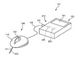
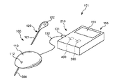
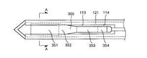
図1は、本発明のグルコース測定装置の実施形態を模式的に示す斜視図であり、グルコース測定装置が有する分析素子が備える脱着部を本体部に装着した状態を示し、図2は、本発明のグルコース測定装置の実施形態を模式的に示す斜視図であり、グルコース測定装置が有する分析素子が備える脱着部を本体部から離脱させた状態を示し、図3は、本発明のグルコース測定装置の実施形態が有する分析素子を皮膚に装着した状態を示す側面図、図4は、図3に示す分析素子が備える検出部を、脱着部が備える針部の中空部内に挿入させた状態を示す側面図、図5は、図3に示す分析素子が備える検出部を、脱着部が備える針部の中空部内に挿入させた状態を示す平面図、図6は、図5に示すA−A線縦断面図、図7は、図3に示す分析素子が備える検出部が有する電極層における電極の位置関係の第1の構成を示す平面図、図8は、図3に示す分析素子が備える検出部を、脱着部が備える針部の中空部から離脱させる方法を説明するための平面図、図9は、図3に示す分析素子が備える検出部のサイズを説明するための平面図、図10は、図3に示す分析素子が備える検出部と、脱着部が備える針部との位置関係を説明するための平面図、図11は、図3に示す分析素子が備える検出部が有する電極層における電極の位置関係の第2の構成を示す平面図、図12は、図3に示す分析素子が備える検出部が有する電極層における電極の位置関係の第3の構成を示す平面図、図13は、図3に示す分析素子が備える検出部が有する電極層における電極の位置関係の第4の構成を示す平面図、図14は、図3に示す分析素子が備える検出部の第1の領域における縦断面図である。なお、以下の説明では、図3、図4、図6、図14中の上側を「上」、下側を「下」と言う。また、図5、図7〜図13、中の紙面手前側を「上」、紙面奥側を「下」と言う。 FIG. 1 is a perspective view schematically showing an embodiment of the glucose measuring device of the present invention, showing a state in which a detachable portion provided in an analysis element included in the glucose measuring device is mounted on a main body, and FIG. FIG. 3 is a perspective view schematically showing an embodiment of the glucose measuring device of the present invention, showing a state in which a desorption part provided in an analysis element included in the glucose measuring device is detached from the main body, and FIG. 3 shows the glucose measuring device of the present invention. FIG. 4 is a side view showing a state where the analysis element according to the embodiment is attached to the skin, and FIG. 4 is a side view showing a state where the detection unit provided in the analysis element shown in FIG. 3 is inserted into the hollow part of the needle part provided in the desorption part 5 is a plan view showing a state in which the detection unit provided in the analytical element shown in FIG. 3 is inserted into the hollow part of the needle part provided in the detachable part, and FIG. 6 is a longitudinal section taken along line AA shown in FIG. FIG. 7 is a plan view of the analytical element shown in FIG. FIG. 8 is a plan view showing a first configuration of the positional relationship of the electrodes in the electrode layer of the detection unit. FIG. 8 is a diagram showing the detection unit included in the analysis element shown in FIG. FIG. 9 is a plan view for explaining the method, FIG. 9 is a plan view for explaining the size of the detection unit included in the analysis element shown in FIG. 3, and FIG. 10 is a detection unit included in the analysis element shown in FIG. FIG. 11 is a plan view illustrating a second configuration of the electrode positional relationship in the electrode layer included in the detection unit included in the analysis element illustrated in FIG. 3; 12 is a plan view showing a third configuration of the electrode positional relationship in the electrode layer of the detection unit included in the analysis element shown in FIG. 3, and FIG. 13 is an electrode of the detection unit included in the analysis element shown in FIG. Plane showing the fourth configuration of the positional relationship of the electrodes in the layer FIG. 14 is a longitudinal sectional view of a first region of the detection unit included in the analysis device shown in FIG. In the following description, the upper side in FIGS. 3, 4, 6, and 14 is referred to as “upper”, and the lower side is referred to as “lower”. 5 and FIGS. 7 to 13, the front side of the paper surface is referred to as “upper”, and the rear side of the paper surface is referred to as “lower”.
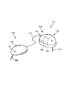
図1、図2に示すグルコース測定装置101は、分析素子100を接続して使用されるものであり、分析素子100と、分析素子100でグルコース濃度に基づく電流値を得るための回路400、得られた電流値を解析する処理回路200を備えた演算装置210および演算装置210で演算することで得られた測定値を表示するモニター151を備える表示部155と、分析素子100を表示部155に装着(接続)するコネクタ131と、分析素子100とコネクタ131とを接続する配線132とを有する。
A
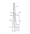
分析素子(検出素子)100は、図1〜図4に示すとおり、皮下組織502に挿入される検出部(センサー基板)300を備える本体部110と、本体部110に対して着脱可能であり、先端側に針部(挿入針)121を備える着脱部120とを有している。
As shown in FIGS. 1 to 4, the analysis element (detection element) 100 is detachable from the
着脱部120は、基端側に位置する把持部122と、先端側に位置する針部121とを有しており、針部121を本体部110が備える貫通孔112に挿通させることで本体部110に装着され(図1参照)、さらに、把持部122を把持した状態で針部121を引き抜くことで離脱可能となっている(図2参照)。
The
針部(挿入針)121は、その先端が鋭利であり、先端側で開口する中空部114を備えており、全体形状が円筒状をなしている。そして、針部121の側面に、その途中から先端まで中空部114を開口するスリット113を備えている。
The needle part (insertion needle) 121 has a sharp tip, is provided with a
このような針部121を備える着脱部120を本体部110に装着して、貫通孔112を貫通して本体部110の下面から突出させる際に、図4〜図6に示すように、検出部300が中空部114の内部に挿入(配置)されるよう構成されている。したがって、本体部110を表皮501に装着する際に、針部121が表皮(生体)501に穿孔されることとなるが、このとき、針部121の中空部114に挿入された検出部300も針部121とともに、表皮501を突き刺し、皮下組織(生体)502に挿入される。この挿入の際に、検出部300は、中空部114内に配置され、針部121で取り囲まれた状態となっているため、針部121を折り曲げる外力が付与されたとしても、針部121が緩衝材としての機能を発揮して、検出部300が折り曲げられるのを的確に抑制または防止することができる。
When attaching / detaching
そして、この皮下組織502への、検出部300が中空部114内に配置された状態での針部121の挿入の後に、把持部122を把持して着脱部120を本体部110から離脱させることで、検出部300を皮下組織502に挿入(残存)させた状態で、針部121を皮下組織502から単独で取り除かれる(引き抜かれる)。このように、着脱部120(針部121)は、本体部110を表皮501に装着した際に、本体部110から突出する検出部300を、経皮的に、皮下組織502へと配置させるための誘導部材(ガイド部材)として用いられる。
Then, after inserting the
なお、針部121の断面形状は、図6に示すように、本実施形態では、真円状をなしているが、検出部300を配置し得る中空部114を備えるものであれば、その断面形状は、特に限定されず、例えば、楕円状の他、三角形状、四角形状のような多角形状をなすものであってもよい。ただし、真円状、楕円状のような円形状をなすものとすることで、検出部300に外力が付与されても、針部121の壁面で均一に押さえることができるため、検出部300が局所的に屈曲するのを的確に抑制または防止することができる。
As shown in FIG. 6, the cross-sectional shape of the
また、着脱部120の本体部110からの離脱、すなわち、検出部300の中空部114からの離脱は、針部121と検出部300との形状の関係により、測定者(生体)に痛みを与えることなく、実施されるが、その詳述な説明は後に行うこととする。
Further, the detachment of the
本体部110は、その全体形状がドーム状をなしており、その下面から突出する検出部300を備えている。この本体部110は、下面に粘着層を備えており、この下面を表皮501に、当接させることで、装着(固定)される。この際、前述した針部121の誘導により、検出部300が皮下組織502に配置される。すなわち、針部(挿入針)121に導かれて、検出部300が皮下組織(生体内)502に挿入される。
The
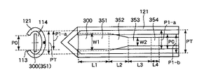
検出部300(本発明のセンサー基板)は、全体形状が短冊状をなし、その平面視において、先端部に設けられた第1の領域351と、基端部(配線132側)に設けられた第3の領域353と、第1の領域351と第3の領域353との間に設けられた第2の領域352とを有している。なお、これら第1の領域351〜第3の領域353が皮下組織502に留置(挿入)される留置領域を構成し、さらに、検出部300は、第3の領域353よりも基端側に設けられ、皮下組織502には留置されない第4の領域354を有しており、この第4の領域354を介して、配線314は、配線132に電気的に接続される。
The detection unit 300 (sensor substrate of the present invention) has a strip shape as a whole, and is provided in the
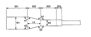
第1の領域351は、図5、図10に示すように、その幅W1が針部121の中空部114の幅PTよりも細く(狭く)、かつ、針部121のスリット113の幅P0よりも太い(広い)幅となっている。これにより、検出部300を中空部114内に配置させているとき、特に、針部121を、皮下組織502に挿入するときに、検出部300がスリット113を介して針部121から離脱するのが確実に防止される。したがって、検出部300が離脱することに起因する痛みを測定者に与えることなく、針部121を皮下組織502に挿入することが可能となる。
As shown in FIGS. 5 and 10, the
さらに、スリット113の一方の端部から、短手方向に対向する他方の中空部114の内面までの距離をP1−aとし、スリット113の他方の端部から、短手方向に対向する一方の中空部114の内面までの距離をP1−bとしたとき、本実施形態では、図10のように、これらの距離が同一となっているP1−a=P1−b(=P1)の関係を満足するが、この時、W1>P1の関係を満足することが好ましい。検出部300がスリット113を介して針部121から離脱するのをより確実に防止することができる。
Further, the distance from one end of the
また、第3の領域353は、図5、図8、図10に示すように、その幅W2が針部121のスリット113の幅P0よりも細い(小さい)幅となっている。これにより、針部121を皮下組織502から取り除く(引き抜く)際に、図8に示すように、針部121を第3の領域353に対応する位置まで引き抜くことで、スリット113を介して中空部114内に位置する第3の領域353(検出部300)を針部121から離脱させることができる。すなわち、針部121を、第1の領域351および第2の領域352が中空部114の外側に位置するまでずらし、その後、第3の領域353を、スリット113を介して中空部114の外側に移動させることにより、検出部300を針部121から離脱させることができる。
Further, as shown in FIGS. 5, 8, and 10, the
なお、第3の領域353の幅W2は、スリット113の幅P0よりも細い幅となっていればよいが、0.2≦W2/P0≦0.9なる関係を満足することが好ましく、0.4≦W2/P0≦0.8なる関係を満足することがより好ましい。これにより、第3の領域353における、スリット113を介した中空部114からの検出部300の離脱を、より円滑に実施することができるとともに、第3の領域353における破断の発生を確実に防止することができる。
Note that the width W2 of the
さらに、第2の領域352は、その先端側では、第1の領域351と同一の幅を有しており、先端側から基端側に向かって、第1の領域351の幅から漸減し、基端側において第3の領域353の幅と同じ幅を有している。上記の通り幅が漸減する第2の領域352を有していることから、図5に示すように、第1の領域351を含む検出部300の全体が中空部114内に配置されている状態から、図8に示すように、検出部300を第3の領域353に対応する位置まで中空部114から引き抜く際に、検出部300がスリット113に係止されるのを的確に抑制または防止することができる。そのため、図8に示すように、第1の領域351および第2の領域352が中空部114から引き抜かれ、第3の領域353が単独で中空部114内に配置される状態にまで、円滑に検出部300をスライド(移動)させることができる。このように、検出部300を針部121に対して円滑に移動させることができる。そのため、この移動に伴い、測定者に痛みを与えるのを的確に抑制または防止することができる。
Furthermore, the
また、第1の領域351および第3の領域353は、本実施形態では、ともに、これら平面視形状が長方形状をなし、それぞれの領域において同じ幅で形成されており、第1の領域351における幅が第3の領域353における幅よりも大きくなっている。これにより、図8に示すように、スリット113を介した中空部114内に位置する第3の領域353の針部121からの離脱をより円滑に実施することができる。すなわち、スリット113に、検出部300の第3の領域353を円滑に通過させることができる。
In the present embodiment, the
さらに、この場合、第1の領域351の幅W1と第3の領域353の幅W2の比W2/W1は、1/2よりも大きく、4/5よりも小さいことが好ましい。すなわち、1/2<W2/W1<4/5なる関係を満足することが好ましい。さらに、1/3<W2/W1<4/5なる関係を満足することがより好ましく、1/2<W2/W1<4/5なる関係を満足することがさらに好ましい。これにより、図5に示すように、検出部300を中空部114内に配置させているときに、スリット113により第1の領域351を確実にガードして、検出部300がスリット113を介して針部121から離脱するのをより確実に防止することができる。また、図8に示すように、針部121を第3の領域353に対応する位置まで引き抜いた後に、中空部114内に位置する第3の領域353を、スリット113内をスライドさせることができるため、検出部300より確実に針部121から離脱させることができる。さらに、検出部300の針部121からの離脱の際に、強度が低くなる第3の領域353において、検出部300が分断されるのを的確に抑制または防止することができる。
Furthermore, in this case, the ratio W2 / W1 between the width W1 of the
なお、第4の領域354の幅は、特に限定されず、例えば、好ましくは10mm以下、より好ましくは3mm以上5mm以下に設定される。これにより、第3の領域353において、スリット113を介して針部121から検出部300を離脱させる際に、この第4の領域354にも、第3の領域353と同一の機能を発揮させることができる。
In addition, the width | variety of the 4th area |
さらに、第1の領域351の針部121の内面に臨む側面と、第2の領域352の針部121の内面に臨む側面とが、中心軸側でなす角度a1、a2、すなわち、第1の領域351と第2の領域352との外面の角度a1、a2は、それぞれ、120°以上180°未満であることが好ましく、135°以上175°未満であることがより好ましく、150°以上170°未満であることがさらに好ましい。また、第2の領域352の針部121の内面に臨む側面と、第3の領域353の針部121の内面に臨む側面とが、中心軸の反対側でなす角度b1、b2、すなわち、第2の領域352と第3の領域353との外面の角度b1、b2は、それぞれ、120°以上180°未満であることが好ましく、135°以上175°未満であることがより好ましく、150°以上170°未満であることがさらに好ましい。角度a1、a2および角度b1、b2が前記範囲内となっていることにより、検出部300の第1の領域351および第2の領域352の中空部114からの離脱を、円滑に実施することができる。その結果、検出部300の第3の領域353を、スリット113を円滑に通過させることが可能となる。さらに、角度a1、a2と角度b1、b2とは、同一の角度となっていることが好ましい。これにより、検出部300の対称性が確保され、検出部300の作製を容易に行うことができる。
Furthermore, angles a1 and a2 formed by the side surface facing the inner surface of the
なお、第3の領域353は、その幅W2が針部121のスリット113の幅P0よりも細い幅となっていればよく、図5、図7〜図10のように、平面視形状が長方形状をなし、第3の領域353において一定の幅W2を有している必要はなく、第2の領域352と同様に、先端側から基端側に向かって、幅W2が漸減するものであってもよい。すなわち、第2の領域352と第3の領域353とは、それらの幅が連続的に漸減して、一体的に形成されているものであってもよい。かかる形状を備える検出部300は、第3の領域353の形成が省略されており、第2の領域352が、第2の領域および第3の領域の機能を併せ持つものとも言うことができる。
Note that the
かかる形状を備える検出部300に、皮下組織502に血管503から移行することで含まれる間質液が、接触する。そのため、検出部300により、間質液中におけるグルコースが検出される。そして、本体部110を表皮501に装着することで、検出部300を皮下組織502に長期に亘って配置させることができるため、この間質液中におけるグルコースの検出を連続的に行うことができる。すなわち、本体部110(分析素子100)は、間質液中におけるグルコース値を連続的に観察するCGMS(continuous glucose monitoring system)に用いられる。
The interstitial fluid contained by moving from the
ここで、検出部300によるグルコースの検出は、以下のような原理を用いて行われる。
Here, the detection of glucose by the
すなわち、酵素を用いることでグルコースの定量化が可能である。酵素としてはグルコースオキシダーゼ、グルコースデヒドロゲナーゼ等を用いることが可能である。例えば、グルコースオキシダーゼの存在下でグルコースと酸素とが酵素近傍に存在すると酵素反応により、下記式(1)のようにグルコン酸と過酸化水素とが生成する。そして、その生成した過酸化水素に電圧(例えば600mV)を印加して電気分解することで発生した電流量を、作用電極と対電極との間で、測定することで過酸化水素の量を定量化することができる。そのため、この定量化された過酸化水素の量に基づいて、グルコースの量を算出することができる。 That is, glucose can be quantified by using an enzyme. As the enzyme, glucose oxidase, glucose dehydrogenase and the like can be used. For example, when glucose and oxygen are present in the vicinity of the enzyme in the presence of glucose oxidase, gluconic acid and hydrogen peroxide are generated as shown in the following formula (1) by the enzyme reaction. Then, the amount of hydrogen peroxide is quantified by measuring the amount of current generated by applying a voltage (for example, 600 mV) to the generated hydrogen peroxide and electrolyzing it between the working electrode and the counter electrode. Can be Therefore, the amount of glucose can be calculated based on the quantified amount of hydrogen peroxide.
なお、過酸化水素の電気分解の際には、作用電極(アノード)側では、下記式(2)のように、過酸化水素の電気分解によりプロトン、酸素および電子が生成され、対電極(カソード)側では、下記式(3)のように、作用電極から供給された電子と、電極付近に存在する酸素および水とが反応することにより水酸化物イオンが生成される。 In the electrolysis of hydrogen peroxide, protons, oxygen and electrons are generated on the working electrode (anode) side by electrolysis of hydrogen peroxide as shown in the following formula (2), and the counter electrode (cathode) On the) side, hydroxide ions are generated by the reaction of electrons supplied from the working electrode with oxygen and water present in the vicinity of the electrode, as shown in the following formula (3).
酵素反応: グルコース+O2+H2O → グルコン酸+H2O2 ・・・ (1)
作用電極: H2O2 → O2+2H++2e− ・・・ (2)
対電極 : O2+H2O+4e− → 4OH− ・・・ (3)
Enzyme reaction: Glucose + O 2 + H 2 O → Gluconic acid + H 2 O 2 (1)
Working electrode: H 2 O 2 → O 2 + 2H + + 2e − (2)
Counter electrode: O 2 + H 2 O + 4e − → 4OH − (3)
以下、かかる原理を用いてグルコースを検出する検出部300の各部について詳述する。
検出部300は、図14に示すとおり、基板301と、導電層(電極)315と、センシング層(酵素層)320とを有している。
Hereinafter, each part of the
As illustrated in FIG. 14, the
基板(ベース基板)301は、検出部300を構成する各部(本実施形態では、導電層315およびセンシング層320)を支持するものである。
The substrate (base substrate) 301 supports each unit (in this embodiment, the
基板301の構成材料としては、大気、水および体液、血液、間質液に対して化学反応することなく安定したものであれば、特に限定されることなく各種材料を用いることができる。具体的には、ガラス、SUSのような無機材料、非晶ポリアリレート(PAR:Polyarylate)、ポリサルホン(PSF:Polysulfone)、ポリエーテルサルホン(PES:Polyethersulfone)、ポリフェニレンスルファイド(PPS:Polyphenylene sulfide)、ポリエーテルエーテルケトン(PEEK:Polyether ether ketone / 別称:芳香族ポリエーテルケトン)、ポリイミド(PI:Polyimide)、ポリエーテルイミド(PEI:Polyetherimide)、フッ素樹脂(Fluorocarbon polymer)や、ナイロン、アミドを含むポリアミド(PA)、ポリエチレンテレフタレート(PET)のようなポリエステル等の樹脂材料等が挙げられ、これらのうちの1種または2種以上を組み合わせて用いることができる。
As a constituent material of the
導電層(電極層)315は、後述するセンシング層320で生成した過酸化水素を電気分解することで発生した電子を検出し、この検出された電子を電流量として測定するものである。
The conductive layer (electrode layer) 315 detects electrons generated by electrolyzing hydrogen peroxide generated in the
この導電層315は、基板301に形成され、作用電極311、対電極312、参照電極313および配線314を有している。
The
各電極311、312、313は、それぞれ独立して、配線314、配線132およびコネクタ131を介して、回路400および処理回路200と電気的に接続されている。これにより、各電極311、312(導電層315)で測定された電流値が、配線314、132を介して表示部155が備える回路400および処理回路200に伝達され、処理回路200を備える演算装置210の解析により、間質液中におけるグルコース値が測定値として算出される。そして、この測定値(グルコース値)がモニター151に表示され、装着者にグルコース値が連続的に知らされる。
Each of the
各電極(検出電極)311、312、313は、図7に示すように、第1の領域351に形成され、これらは、それぞれ、第2の領域352および第3の領域353に形成された配線314を介して、配線(配線部)132に電気的に接続されている。
As shown in FIG. 7, the electrodes (detection electrodes) 311, 312, and 313 are formed in the
また、第1の領域351に形成された各電極311、312、313は、長手方向(長軸方向)に直交する短手方向(直列方向)に沿って、この順で3つ並んで配置されている。これにより、検出部300の幅が若干大きくなる傾向を示すものの、検出部の長さを短くすることが可能となるため、検出部300を皮下組織502の深部まで挿入させる必要がなくなると言う利点が得られる。また、均一な深部における間質液のグルコース濃度を測定することができるため、より優れた精度でグルコース濃度が検出される。
In addition, three
なお、第1の領域351に形成される各電極311、312、313は、短手方向に3つ並んで配置される第1の構成の他、図11〜図13に示す、第2〜第4の構成のものであってもよい。
Each of the
すなわち、図11に示す第2の構成では、第1の領域351の先端側で、作用電極311と参照電極313とが短手方向に並んで配置され、第1の領域351の基端側で、対電極312が配置されている。換言すれば、第1の領域351には長軸方向に交差する並列方向に配置された2個の電極311、313と、作用電極311に対して長軸方向に沿った直列方向に配置された電極312とが設けられている。これにより、第1の構成および第4の構成に比較して、平均的な検出部300の幅および長さを備えるものとすることができる。
That is, in the second configuration shown in FIG. 11, the working
また、図12に示す第3の構成では、第1の領域351の先端側で、作用電極311が配置され、第1の領域351の基端側で、対電極312と参照電極313とが短手方向に並んで配置されている。これにより、第1の構成および第4の構成に比較して、平均的な検出部300の幅および長さを備えるものとすることができる。
In the third configuration shown in FIG. 12, the working
さらに、図13に示す第4の構成では、各電極311、312、313が、長手方向に沿って、この順で先端側から3つ並んで配置されている。これにより、検出部300の長さが若干長くなる傾向を示すものの、検出部の幅を小さくすることが可能となるため、検出部300を皮下組織502に挿入させる際に生体に対する痛みをより低減させることができると言う利点が得られる。
Further, in the fourth configuration shown in FIG. 13, three
以上のことから、第2の構成〜第4の構成のものを用いることにより、検出部300を皮下組織502に挿入させる際に生体に対する痛みを低減させることができる。また、第1の構成〜第3の構成のものを用いることにより、優れた精度でグルコース濃度を検出することができる。
From the above, by using the second to fourth configurations, it is possible to reduce pain to the living body when the
なお、このような第1の構成〜第4の構成、さらには、これらが備える各電極311、312、313の面積、長さおよび幅等は、グルコース測定装置に求められる測定精度等に応じて適宜選択される。
Note that the first configuration to the fourth configuration as well as the areas, lengths, widths, and the like of the
また、第1の構成〜第4の構成における各電極311、312、313の位置は、図示のものに限定されず、任意の位置に配置することができる。
The positions of the
さらに、各電極311、312、313の大きさは、特に限定されないが、例えば、作用電極311および対電極312は、幅(短辺)が0.1mm以上0.3mm以下程度であることが好ましく、0.2mm程度であることがより好ましい。また、長さ(長辺)が1.0mm以上3.0mm以下程度であることが好ましく、2.0mm程度であることがより好ましい。
Further, the size of each of the
このような大きさとなっている作用電極311および対電極312は、同一の面積を有するものであっても異なる面積を有するものであってもよいが、面積が対電極312>作用電極311なる関係を満足することが好ましい。これは、電気化学的に作用電極311で授受する電子の量を、対電極312において逆反応でこなす必要があるため、前記関係を満足することにより、前記逆反応の安定化が図られる。
The working
参照電極313は、幅(短辺)が0.01mm以上0.2mm以下程度であることが好ましい。また、長さ(長辺)が0.1mm以上3.0mm以下程度であることが好ましい。
The
このような大きさとなっている参照電極313は、作用電極311および対電極312に対して、20%以上100%以下の面積を有していることが好ましい。参照電極313は、グルコース濃度を算出するために測定する電流値を検出するために用いられるものではないため、作用電極311および対電極312に比較してその面積が小さくなっていてもよい。しかしながら、皮下組織502への留置の際に、間質液に含まれるタンパク質等が付着することで、特性の低下を招くことを防止することを目的に、前記範囲内の面積を有していることが好ましい。
The
また、各電極311、312および313の構成材料としては、酵素電極として用いることが可能であれば、特に限定されず、それぞれ、例えば、金、銀、白金またはこれらを含む合金のような金属材料、ITOのような金属酸化物系材料、カーボン(グラファイト)のような炭素系材料等が挙げられる。
Further, the constituent material of each of the
なお、各電極311、312、313の成膜は、各電極311、312、313を白金、金またはそれらの合金で構成する場合、スパッタ法、メッキ法、真空加熱蒸着法により成膜可能である。また、各電極311、312、313をカーボングラファイトで構成する場合、カーボングラファイトを適当な溶剤に溶かし込んだバインダーに混ぜ込んで塗布することで実現できる。
The
センシング層320は、導電層315上に積層して形成されており、センシング層320の上面に接触した間質液から浸透したグルコースから酵素反応により過酸化水素を生成して、この過酸化水素を、前述した導電層315に供給するものであり、グルコースから過酸化水素を生成する酵素反応によりグルコースを感知するものである。
The
このセンシング層320は、本実施形態では、図14に示すように、分析物感知層321と、分析物調整層322とを有しており、これらが、導電層315側からこの順で積層された積層体で構成されている。以下、これら各層について説明する。
In this embodiment, as shown in FIG. 14, the
分析物感知層(酵素層)321は、作用電極311、対電極312および参照電極313を覆って形成されており、分析物調整層322を介して浸透したグルコースから酵素反応により過酸化水素を生成するものである。そして、生成した過酸化水素を、導電層315に供給するものである。
The analyte sensing layer (enzyme layer) 321 is formed so as to cover the working
この分析物感知層321は、酵素を含んで構成される層であり、前述の通り分析素子100が間質液中におけるグルコースを検出(検知)するものであるため、この酵素としては、グルコースオキシダーゼ(GOD)が好ましく用いられる。グルコースオキシダーゼによれば、前記式(1)で表わされる酵素反応を、優れた活性度で進行させることができるため、O2およびH2Oの存在下で、グルコースから過酸化水素を確実に生成させることができる。
The
また、分析物感知層321には、酵素の他に、分析物感知層321中に酵素を保持することを目的に、樹脂材料が含まれる。
In addition to the enzyme, the
樹脂材料としては、特に限定されないが、例えば、メチルセルロース(MC)、アセチルセルロース(酢酸セルロース)、ポリビニルピロリドン(PVP)、ポリビニルアルコール(PVA)およびポリビニルアルコール−ポリ酢酸ビニル共重合体(PVA−PVAc)等が好ましく用いられ、これらのうちの1種または2種以上を組み合わせて用いることができる。これらの樹脂材料を用いることにより、分析物感知層321中に酵素を保持し、分析物感知層321外に酵素が移動することを抑制することができる。
The resin material is not particularly limited. For example, methyl cellulose (MC), acetyl cellulose (cellulose acetate), polyvinyl pyrrolidone (PVP), polyvinyl alcohol (PVA), and polyvinyl alcohol-polyvinyl acetate copolymer (PVA-PVAc). Etc. are preferably used, and one or more of these can be used in combination. By using these resin materials, the enzyme can be held in the
さらに、分析物感知層321には、結合剤もしくは硬化剤の他、アルブミン、リン酸緩衝材等が含まれていてもよい。
Further, the
結合剤もしくは硬化剤は、アルデヒド、イソシアネート等の官能基を分子内に2つ以上有している材料が挙げられる。このような結合剤もしくは硬化剤が分析物感知層321中に含まれることにより、分析物感知層321は、優れた保持率で酵素を分析物感知層321中に保持し得るものとなる。
Examples of the binder or curing agent include materials having two or more functional groups such as aldehyde and isocyanate in the molecule. By including such a binder or curing agent in the
この結合剤、硬化剤としては、具体的には、例えば、グルタルアルデヒド、トルエンジイソシアネート、イソホロンジイソシアネート等が挙げられ、これらのうちの1種または2種以上を組み合わせて用いることができる。また、UV硬化性を利用した結合剤、硬化剤としては、例えば、ポリ(ビニルアルコール)−スチリルピリジニウム化合物(PVA−SbQ)等が挙げられる。 Specific examples of the binder and curing agent include glutaraldehyde, toluene diisocyanate, isophorone diisocyanate, and the like, and one or more of these can be used in combination. Moreover, as a binder and a hardening | curing agent using UV curability, a poly (vinyl alcohol) -styryl pyridinium compound (PVA-SbQ) etc. are mentioned, for example.
なお、このような結合剤もしくは硬化剤を含む分析物感知層321は、結合剤もしくは硬化剤と、これらが備える官能基と結合できる官能基、具体的には水酸基、アミノ基、エポキシ基等を末端に有する樹脂材料と、酵素とを混合した樹脂組成物を硬化させることにより得ることができる。
The
さらに、UV硬化性を利用した結合剤、硬化剤としては、ポリ(ビニルアルコール)−スチリルピリジニウム化合物(PVA−SbQ)を用いる場合には、官能基を末端に有する樹脂材料の添加を省略して、PVA−SbQと酵素とを含有する樹脂組成物を硬化させることにより得られた硬化物で、分析物感知層321を構成することもできる。この場合、分析物感知層321は、PVA−SbQで構成される多孔体に、酵素が保持され、分析物調整層322側から浸透してくる間質液を円滑に分析物感知層321内に取り込むことができ、間質液内に含まれるグルコースと酵素との接触機会を増大させることができ、前記式(1)で表わされる酵素反応を、円滑に進行させることができるため、O2およびH2Oの存在下で、グルコースから過酸化水素を確実に生成させることができる。また、PVA−SbQで構成される多孔体に、酵素を強固に保持することができるため、酵素が分析物調整層322側に移行するのを的確に抑制または防止することができる。
Furthermore, when using a poly (vinyl alcohol) -styrylpyridinium compound (PVA-SbQ) as a binder or curing agent using UV curability, the addition of a resin material having a functional group at the end is omitted. The
また、アルブミンとしては、人アルブミン、牛アルブミン等が挙げられ、アルブミンが含まれることにより、酵素の保護・安定化を図ることができる。 Examples of albumin include human albumin and bovine albumin. By containing albumin, the enzyme can be protected and stabilized.
このような分析物感知層321の平均厚さは、特に限定されないが、0.1μm以上10μm以下程度であるのが好ましく、0.5μm以上5.0μm以下程度であるのがより好ましい。これにより、分析物調整層322側から浸透したグルコースと分析物感知層321に保持された酵素との酵素反応により過酸化水素を円滑に生成することができるとともに、生成した過酸化水素を、円滑に導電層315に供給することができる。
The average thickness of the
分析物調整層322は、分析物感知層321の上側に積層され、この分析物調整層322により、分析物感知層321が測定対象(間質液、さらには血液)と接触することを抑制または防止しつつ、グルコースを透過させて、分析物感知層321に円滑に浸透させる機能を発揮するものである。さらに、分析物感知層321に保持されている酵素が、間質液側に漏出するのを防止するブロッキング層としての機能も発揮する。
The
また、かかる機能を備える分析物調整層322は、グルコースよりも酸素をより多く透過(浸透)させ得ることが好ましい。これにより、上記式(1)〜(3)を用いたグルコースの検出において、酸素が不足することに起因して、グルコースの測定値が見かけ上、低下してしまうのを的確に抑制または防止することができる。すなわち、グルコース測定値の検出精度の向上が図られる。
Moreover, it is preferable that the
このような分析物調整層322としては、特に限定されないが、例えば、イソシアネート化合物等の架橋剤と、末端水酸基を備えるポリマーであるポリエチレングリコール(PEG)、ポリプロピレングリコール(PPG)、アクリル酸4−ヒドロキシブチル等を単体もしくは混合させたものとを用いて、ウレタン結合を生成させて架橋構造を構築したものが特に好ましく用いられる。これにより、上述した分析物調整層322としての機能をより顕著に発揮させることができる。
Such an
また、その他、イソシアネートとアミノ基とを用いることで尿素樹脂を形成させた、アミノプロピルポリシロキサン等で構成されるものを用いることができ、さらには、ポリジメチルシロキサンのようなシロキサン樹脂で構成されるものを用いることもできる。 In addition, it is possible to use those composed of aminopropylpolysiloxane or the like in which urea resin is formed by using isocyanate and amino group, and further composed of siloxane resin such as polydimethylsiloxane. A thing can also be used.
このような分析物調整層322の平均厚さは、特に限定されないが、0.1μm以上10μm以下程度であるのが好ましく、0.5μm以上5.0μm以下程度であるのがより好ましい。これにより、分析物調整層322内にグルコースを円滑に透過させることができるとともに、分析物感知層321に保持されていた酵素が、間質液側に漏出するのを的確に抑制または防止することができる。
The average thickness of the
なお、センシング層320は、前述した、分析物感知層321および分析物調整層322の他に、他の層を備えるものであってもよく、このような層としては、例えば、分析物感知層321の下側に積層されるノイズ除去層、および、分析物感知層321と分析物調整層322との間に形成される中間層等が挙げられる。
The
ノイズ除去層は、間質液中に含まれる可能性を有する、アセトアミノフェン、アスコルビン酸、および尿酸等の化合物が分析物感知層321を透過して導電層315に到達することに起因する、グルコース測定値の検出感度の低下を阻止するために設けられる。
The noise removal layer is caused by a compound such as acetaminophen, ascorbic acid, and uric acid, which may be included in the interstitial fluid, passing through the
また、中間層は、酵素が分析物調整層322側に移行するのを防止するバリア層としての機能を発揮させるために設けられる。
The intermediate layer is provided in order to exhibit a function as a barrier layer that prevents the enzyme from moving to the
なお、検出部300において、導電層315が備える作用電極311、対電極312、参照電極313および配線314の全体を、すなわち、第1の領域351〜第3の領域353の全体を分析物感知層321で覆うようにしてもよいし、作用電極311、対電極312および参照電極313を、すなわち第1の領域351の全体を覆うようにしてもよいし、さらには、作用電極311および対電極312を選択的に覆うようにしてもよいし、作用電極311を選択的に覆うようにしてもよい。
Note that in the
また、表示部155は、図1、2に示すとおり、その内部に配設され、配線314、132を介して電気的に接続された、検出部300を駆動させるための回路400を有している。
Further, as shown in FIGS. 1 and 2, the
この回路400には、検出部300が備える作用電極311、参照電極313、および対電極312が電気的に接続されている。
The
回路400の作動により、作用電極311と参照電極313との間では、例えば、600mVの電圧の差が維持され、この差が、検出部300に対する印加電圧となり、その結果、センシング層320に含まれる過酸化水素が電気分解することで、電子が生成される。そして、この電子を、作用電極311と対電極312との間で、グルコース濃度に基づく電流値として回路400で測定し、また、この電流値を処理回路200が備える演算装置210で解析することで、グルコース値が測定値として算出され、さらに、この測定値がモニター151により表示される。
By the operation of the
<測定方法>
また、上記のグルコース測定装置101を用いた、間質液中におけるグルコース値の測定は、具体的には、例えば、以下のようにして行われる。
<Measurement method>
Moreover, the measurement of the glucose level in the interstitial fluid using the
図15は、本発明のグルコース測定装置を用いて、グルコース値を測定する方法を示すフローチャートである。 FIG. 15 is a flowchart showing a method for measuring a glucose value using the glucose measuring device of the present invention.
[1]まず、検出部300を皮下組織502に挿入して、検出部300(センシング層320)を間質液に接触させることで、安定化させる(S1)。
[1] First, the
[2]次に、作用電極311と参照電極313との間に定電圧を所定の長さで印加する。これにより、安定化の際にセンシング層320の作用電極311近傍に生じた過酸化水素を上記式(2)のように電気分解することで、センシング層320の作用電極311近傍を初期設定させる(S2)。
[2] Next, a constant voltage is applied between the working
[3]次に、一定時間の間隔をあけた後に、作用電極311と参照電極313との間に定電圧を所定の長さで印加する。これにより、センシング層320の作用電極311近傍に生じた過酸化水素が上記式(2)のように電気分解され、その結果、生じた電子を、作用電極311と対電極312との間に流れた電流値として測定することで、間質液中におけるグルコース値が求められる(S3)。
[3] Next, after a certain time interval, a constant voltage is applied between the working
なお、この工程[3]は、1回であってもよいが、工程[3]を繰り返して行い、この間に測定されたグルコース値の平均値を求めることにより、グルコース値が平均化されるため、グルコース値をより優れた信頼度で求めることができる。 In addition, although this process [3] may be performed once, since glucose value is averaged by repeating process [3] and calculating | requiring the average value of the glucose value measured in the meantime, , The glucose level can be determined with higher reliability.
以上のような工程[1]〜工程[3]を、所定の間隔を空けて繰り返して行うことで、
間質液中におけるグルコース値(グルコース濃度)を連続的に測定することができる。
By repeatedly performing the above steps [1] to [3] at a predetermined interval,
The glucose level (glucose concentration) in the interstitial fluid can be continuously measured.
<インスリン供給装置>
また、本発明の分析素子は、上記のようにグルコース測定装置に装着される他、例えば、インスリン供給装置(本発明のインスリン供給装置)に装着される。
<Insulin supply device>
In addition to being mounted on the glucose measuring device as described above, the analytical element of the present invention is mounted on, for example, an insulin supply device (insulin supply device of the present invention).
図16は、本発明の分析素子をインスリン供給装置に装着した状態を模式的に示す斜視図である。 FIG. 16 is a perspective view schematically showing a state in which the analysis element of the present invention is mounted on an insulin supply device.
図16に示すインスリン供給装置(インスリンポンプ)171は、分析素子100を接続して使用されるものであり、検出部300を備える分析素子100と、分析素子100で得られた電流値を解析する処理回路200を備えた演算装置210および演算装置210で演算することで得られた測定値に基づいて皮下組織502にインスリンを供給(投与)する針部172を備える供給部175と、分析素子100を供給部175に装着(接続)するコネクタ131と、処理回路200とコネクタ131とを接続する配線132とを有する。このようなインスリン供給装置171では、作用電極311と対電極312との間に流れた電流値が、本体部110が備える回路400および配線132を介して、処理回路200に伝達され、処理回路200を備える演算装置210の解析により、間質液中におけるグルコース値(グルコース濃度)が測定値として算出される。そして、この測定値(グルコース値)に基づいて、すなわち測定値が設定された濃度よりも高い場合に、インスリン供給装置171が作動し、針部172を介して、装着者にインスリンが自動的に投与される。
An insulin supply device (insulin pump) 171 shown in FIG. 16 is used by connecting the
以上、本発明のセンサー基板、分析素子、グルコース測定装置およびインスリン供給装置を図示の実施形態に基づいて説明したが、本発明はこれに限定されるものではない。 As mentioned above, although the sensor board | substrate, the analysis element, glucose measuring device, and insulin supply apparatus of this invention were demonstrated based on embodiment of illustration, this invention is not limited to this.
例えば、本発明のセンサー基板、分析素子、グルコース測定装置およびインスリン供給装置における各部の構成は、同様の機能を有する任意の構成のものに置換することができる。また、本発明に、他の任意の構成物が付加されていてもよい。また、本発明は、前記グルコース測定装置およびインスリン供給装置のうちの、任意の2以上の構成(特徴)を組み合わせたものであってもよい。 For example, the configuration of each part in the sensor substrate, the analysis element, the glucose measurement device, and the insulin supply device of the present invention can be replaced with any configuration having the same function. In addition, any other component may be added to the present invention. The present invention may be a combination of any two or more configurations (features) of the glucose measuring device and the insulin supply device.
また、検出部300を皮下組織に挿入する他、皮内に挿入するようにしてもよい。
さらに、グルコース測定装置およびインスリン供給装置において、分析素子で測定された電流値は、配線を介することなく、処理回路に伝達するようにしてもよく、例えば、通信手段を介して無線で、電流値を処理回路に伝達するようにしてもよい。
In addition to inserting the
Furthermore, in the glucose measurement device and the insulin supply device, the current value measured by the analysis element may be transmitted to the processing circuit without going through the wiring. For example, the current value wirelessly via the communication means May be transmitted to the processing circuit.
また、グルコース測定装置において、分析素子と表示部とは配線を介して接続されているものに限らず、これらが一体的に形成されているものであってもよいし、インスリン供給装置において、分析素子と供給部とは配線を介して接続されているものに限らず、これらが一体的に形成されているものであってもよい。 Further, in the glucose measuring device, the analysis element and the display unit are not limited to those connected via wiring, and these may be integrally formed. The element and the supply unit are not limited to those connected via wiring, but may be formed integrally.
次に、本発明の具体的実施例について説明する。
1.実施例の検討
1−1.検出部の製造
(実施例1)
<1> まず、平均厚さ0.5mmの透明なガラス基板を基板301として用意した。
なお、第1の領域351、第2の領域352、第3の領域353および第4の領域354の長さを、それぞれ、L1、L2、L3およびL4とし、第1の領域351および第3の領域353の幅を、それぞれ、W1およびW2としたとき、これらの大きさの関係が表1の関係を満足する基板301を用意した。
Next, specific examples of the present invention will be described.
1. 1. Examination of Examples 1-1. Production of detector (Example 1)
<1> First, a transparent glass substrate having an average thickness of 0.5 mm was prepared as the
Note that the lengths of the
<2> 次いで、ガラス基板上に、マスクスパッタ法により平均厚さ200nmのパターニングされた白金膜を、作用電極311、対電極312および参照電極313を備える導電層(電極層)315として形成した。
<2> Next, a patterned platinum film having an average thickness of 200 nm was formed as a conductive layer (electrode layer) 315 including a working
なお、作用電極311、対電極312および参照電極313は、図7に示す第1の構成を満足する位置に、第1の領域351に対して形成し、それぞれの長辺および短辺は、表1の大きさを満足するものを形成した。
Note that the working
<3> 次いで、GOD(グルコースオキシダーゼ 活性度 150U/mg)5mgを超純水6.1gに溶解させGOD溶液とし、さらに得られたGOD溶液を1.22g秤量し、PVA−SbQ(13.3%水溶液)1.0gと混合させることで、分析物感知層形成用材料を調製した。 <3> Subsequently, 5 mg of GOD (glucose oxidase activity 150 U / mg) was dissolved in 6.1 g of ultrapure water to obtain a GOD solution, and 1.22 g of the obtained GOD solution was weighed to obtain PVA-SbQ (13.3). The material for forming an analyte sensing layer was prepared by mixing with 1.0 g of a% aqueous solution.
そして、この分析物感知層形成用材料を、作用電極、対電極および参照電極の全面に、シリンジで滴下し1000rpm−300secの条件でスピンコート法を用いて塗布することで膜厚0.8μmの液状被膜を成膜した後、5分間自然乾燥させることで薄膜を得た。その後、365nmの紫外線を5分間照射して不溶化膜(硬化膜)を形成することで、分析物感知層321を成膜した。
Then, the analyte sensing layer forming material is dropped on the entire surface of the working electrode, the counter electrode, and the reference electrode with a syringe and applied using a spin coat method under the condition of 1000 rpm-300 sec. After forming a liquid film, the film was naturally dried for 5 minutes to obtain a thin film. Thereafter, the
<4> 次いで、PPG(ポリプロピレングリコール)トリオール型(300)0.45g、トルエン0.5g、イソホロンジイソシアネートが0.5g、ジアザビシクロウンデセン(DBU)1滴とを撹拌させながら混合することで、分析物調整層形成用材料を調製した。 <4> Subsequently, 0.45 g of PPG (polypropylene glycol) triol type (300), 0.5 g of toluene, 0.5 g of isophorone diisocyanate, and 1 drop of diazabicycloundecene (DBU) are mixed with stirring. Then, an analyte adjusting layer forming material was prepared.
そして、この分析物調整層形成用材料を、分析物感知層の全面に、シリンジで分析物調製層形成用材料を滴下し1000rpm−300secの条件でスピンコート法を用いて塗布した後、24時間放置してウレタンを生成させることで、膜厚0.2μmの、ウレタン結合を含む架橋構造を備え、ウレタン結合の形成の際に残存したイソシアネート基を有する構成をなす分析物調整層322を成膜した。
以上の工程により、図7の構成をなす実施例1の検出部300を製造した。
Then, this analyte adjusting layer forming material is applied to the entire surface of the analyte sensing layer by dropping the analyte preparing layer forming material with a syringe and using a spin coat method under conditions of 1000 rpm to 300 sec, and then 24 hours. By forming the urethane by leaving it to stand, the
The
(実施例2)
前記工程<1>において用意する基板301として、表1に示す長さ(L1〜L4)を有するものを用いたこと以外は前記実施例1と同様にして、図7の構成をなす実施例2の検出部300を製造した。
(Example 2)
Example 2 having the configuration shown in FIG. 7 is the same as Example 1 except that the
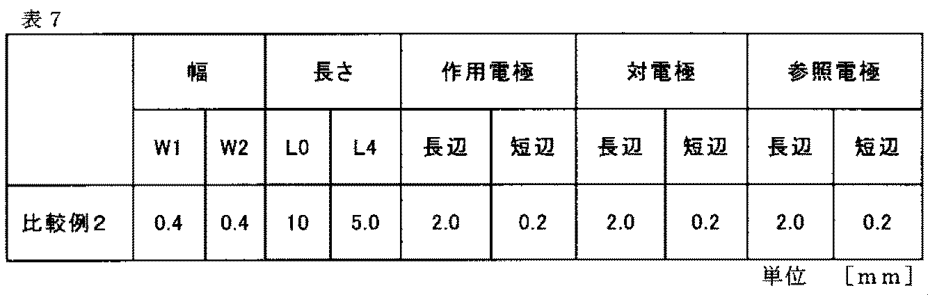
(実施例3、実施例4)
前記工程<1>において用意する基板301として、表2に示す幅(W1、W2)および長さ(L1〜L4)を有するものを用い、さらに、前記工程<2>において、作用電極311、対電極312および参照電極313を、図11に示す第2の構成を満足する位置に、第1の領域351に対して形成し、それぞれの長辺および短辺が表2の大きさを満足するものとしたこと以外は前記実施例1と同様にして、図11の構成をなす実施例3、4の検出部300を製造した。
(Example 3, Example 4)
As the
(実施例5)
前記工程<1>において用意する基板301として、表3に示す幅(W1、W2)および長さ(L1〜L4)を有するものを用い、さらに、前記工程<2>において、作用電極311、対電極312および参照電極313を、図12に示す第3の構成を満足する位置に、第1の領域351に対して形成し、それぞれの長辺および短辺が表3の大きさを満足するものとしたこと以外は前記実施例1と同様にして、図12の構成をなす実施例5の検出部300を製造した。
(Example 5)
As the
(実施例6、実施例7)
前記工程<1>において用意する基板301として、表4に示す幅(W1、W2)および長さ(L1〜L4)を有するものを用い、さらに、前記工程<2>において、作用電極311、対電極312および参照電極313を、図13に示す第4の構成を満足する位置に、第1の領域351に対して形成し、それぞれの長辺および短辺が表4の大きさを満足するものとしたこと以外は前記実施例1と同様にして、図13の構成をなす実施例6、7の検出部300を製造した。
(Example 6, Example 7)
As the
1−2.評価
各実施例の検出部300を、予め用意した針部121に対して、図10に示す状態となるように、中空部114内に挿通させた。
1-2. Evaluation The
なお、針部121としては、表5に示すような、長さの関係を満足するものとして、断面形状が楕円状および円状(真円状)をなすものを、別途、用意し、それぞれに対して、各実施例の検出部300を挿通させた。
In addition, as the
そして、この検出部300が中空部114内に配置された針部121を、皮膚モデルに対して穿刺した後、針部121を単独で離脱させた。すなわち、皮膚モデル内に、検出部300を留置した状態で、皮膚モデルから針部121を抜去した。
Then, after the
その後、皮膚モデル内に留置された検出部300における折れの発生の有無を目視にて確認した。
この結果を、表5に示す。
Then, the presence or absence of generation | occurrence | production of the folding in the
The results are shown in Table 5.
表5に示すように、各実施例の検出部300では、針部121の中空部114に対して、検出部300において、折れを生じさせることなく、検出部300を挿通させることが可能であった。
As shown in Table 5, in the
2.比較例の検討
2−1.検出部の製造
2. 2. Examination of Comparative Example 2-1. Detection unit manufacturing
(比較例1)
前記工程<1>において用意する基板301として、表6に示す幅(W1、W2)および長さ(L0、L4)を有するものを用いたこと以外は前記実施例1と同様にして、作用電極311、対電極312および参照電極313の配置が図7の構成をなす比較例1の検出部300を製造した。
(Comparative Example 1)
The working electrode was prepared in the same manner as in Example 1 except that the
なお、比較例1では、W1=W2となっており、第1の領域351〜第4の領域354の幅が同一となっていることから、第1の領域351、第2の領域352および第3の領域353の長さL1、L2およびL3の合計(L1+L2+L3)をL0として示すこととする。
In Comparative Example 1, since W1 = W2 and the widths of the
(比較例2)
前記工程<1>において用意する基板301として、表7に示す幅(W1、W2)および長さ(L0、L4)を有するものを用い、さらに、前記工程<2>において、作用電極311、対電極312および参照電極313を、図11に示す第2の構成を満足する位置に、第1の領域351に対して形成し、それぞれの長辺および短辺が表7の大きさを満足するものとしたこと以外は前記実施例1と同様にして、対電極312および参照電極313の配置が図11の構成をなす比較例2の検出部300を製造した。
(Comparative Example 2)
As the
なお、比較例2では、W1=W2となっており、第1の領域351〜第4の領域354の幅が同一となっていることから、第1の領域351、第2の領域352および第3の領域353の長さL1、L2およびL3の合計(L1+L2+L3)をL0として示すこととする。
In Comparative Example 2, since W1 = W2 and the widths of the
(比較例3)
前記工程<1>において用意する基板301として、表8に示す幅(W1、W2)および長さ(L0、L4)を有するものを用い、さらに、前記工程<2>において、作用電極311、対電極312および参照電極313を、図12に示す第3の構成を満足する位置に、第1の領域351に対して形成し、それぞれの長辺および短辺が表8の大きさを満足するものとしたこと以外は前記実施例1と同様にして、対電極312および参照電極313の配置が図12の構成をなす比較例3の検出部300を製造した。
(Comparative Example 3)
As the
なお、比較例3では、W1=W2となっており、第1の領域351〜第4の領域354の幅が同一となっていることから、第1の領域351、第2の領域352および第3の領域353の長さL1、L2およびL3の合計(L1+L2+L3)をL0として示すこととする。
In Comparative Example 3, since W1 = W2 and the widths of the
2−2.評価
各比較例の検出部300を、予め用意した針部に対して、針部が備える凹部内に配置させた。
2-2. Evaluation The
なお、針部121としては、表9に示すような、長さの関係を満足するものとして、断面形状が半円状をなし、凹部を備えるものを、別途、用意し、それぞれに対して、各比較例の検出部300を凹部内に配置させた。また、表9中のPTは、開口部(スリット)の幅を表し、P2は、凹部(開口部)の最大深さを表す。
In addition, as the
そして、この検出部300が凹部内に配置された針部を、皮膚モデルに対して穿刺した後、針部を単独で離脱させた。すなわち、皮膚モデル内に、検出部300を留置した状態で、皮膚モデルから針部を抜去した。
And after puncturing the skin part with this
その後、皮膚モデル内に留置された検出部300における折れの発生の有無を目視にて確認した。
この結果を、表9に示す。
Then, the presence or absence of generation | occurrence | production of the folding in the
The results are shown in Table 9.
表9に示すように、各比較例の検出部300では、皮膚モデルに対する検出部300の挿入(穿刺)の際に、針部で検出部300を保持させることができず、これに起因して、検出部300に折れが生じる結果を示した。
As shown in Table 9, in the
100…分析素子、101…グルコース測定装置、110…本体部、112…貫通孔、113…スリット、114…中空部、120…着脱部、121…針部、122…把持部、131…コネクタ、132…配線、151…モニター、155…表示部、171…インスリン供給装置、172…針部、175…供給部、200…処理回路、210…演算装置、300…検出部、301…基板、311…作用電極、312…対電極、313…参照電極、314…配線、315…導電層、320…センシング層、321…分析物感知層、322…分析物調整層、351…第1の領域、352…第2の領域、353…第3の領域、354…第4の領域、400…回路、501…表皮、502…皮下組織、503…血管
DESCRIPTION OF
Claims (8)
前記センサー基板の先端部に設けられて、検出電極を含む第1の領域と、
配線部を含み、前記挿入針のスリットの幅より小さい幅を有する第3の領域と、
前記第1の領域と前記第3の領域との間に設けられ、前記第1の領域の幅から漸減して前記第3の領域の幅と同じ幅を有する第2の領域と、
を備えたことを特徴とするセンサー基板。 A sensor substrate that is guided by an insertion needle inserted into the living body and inserted into the living body,
A first region provided at a tip of the sensor substrate and including a detection electrode;
A third region including a wiring portion and having a width smaller than the width of the slit of the insertion needle;
A second region provided between the first region and the third region, having a width that is gradually reduced from the width of the first region and having the same width as the third region;
A sensor substrate comprising:
前記第1の領域と前記第3の領域では、それぞれの領域において同じ幅で形成されていることを特徴とするセンサー基板。 The sensor substrate according to claim 1,
The sensor substrate, wherein the first region and the third region are formed with the same width in each region.
前記第1の領域の幅と前記第3の領域の幅の比は、1/2よりも大きく、4/5よりも小さいことを特徴とするセンサー基板。 The sensor substrate according to claim 1 or 2,
The ratio of the width | variety of the said 1st area | region and the width | variety of the said 3rd area | region is larger than 1/2 and smaller than 4/5, The sensor board | substrate characterized by the above-mentioned.
前記第1の領域と前記第2の領域との外面の角度は、120°以上であることを特徴とするセンサー基板。 The sensor substrate according to any one of claims 1 to 3,
The sensor substrate according to claim 1, wherein an outer surface angle of the first region and the second region is 120 ° or more.
前記第1の領域には長軸方向に交差する並列方向に配置された2個の電極と、前記電極のいずれか一方と前記長軸方向に沿った直列方向に配置された電極と、を備えたことを特徴とするセンサー基板。 The sensor substrate according to any one of claims 1 to 4,
The first region includes two electrodes arranged in a parallel direction intersecting the major axis direction, and one of the electrodes and an electrode arranged in a series direction along the major axis direction. A sensor substrate characterized by that.
Priority Applications (4)
| Application Number | Priority Date | Filing Date | Title |
|---|---|---|---|
| JP2015256064A JP2017118911A (en) | 2015-12-28 | 2015-12-28 | Sensor substrate, analysis element, glucose measuring device, and insulin feeding device |
| US15/388,696 US20170182247A1 (en) | 2015-12-28 | 2016-12-22 | Sensor substrate, analysis element, glucose measurement device, and insulin supply device |
| CN201611216716.0A CN106913347A (en) | 2015-12-28 | 2016-12-23 | Sensor base plate, analysis element, glucose assays and insulin feedway |
| EP16206947.0A EP3187103A1 (en) | 2015-12-28 | 2016-12-27 | Sensor substrate, analysis element, glucose measurement device, and insulin supply device |
Applications Claiming Priority (1)
| Application Number | Priority Date | Filing Date | Title |
|---|---|---|---|
| JP2015256064A JP2017118911A (en) | 2015-12-28 | 2015-12-28 | Sensor substrate, analysis element, glucose measuring device, and insulin feeding device |
Publications (1)
| Publication Number | Publication Date |
|---|---|
| JP2017118911A true JP2017118911A (en) | 2017-07-06 |
Family
ID=57794076
Family Applications (1)
| Application Number | Title | Priority Date | Filing Date |
|---|---|---|---|
| JP2015256064A Pending JP2017118911A (en) | 2015-12-28 | 2015-12-28 | Sensor substrate, analysis element, glucose measuring device, and insulin feeding device |
Country Status (4)
| Country | Link |
|---|---|
| US (1) | US20170182247A1 (en) |
| EP (1) | EP3187103A1 (en) |
| JP (1) | JP2017118911A (en) |
| CN (1) | CN106913347A (en) |
Cited By (2)
| Publication number | Priority date | Publication date | Assignee | Title |
|---|---|---|---|---|
| WO2021024640A1 (en) * | 2019-08-02 | 2021-02-11 | テルモ株式会社 | Insertion device and needle member |
| WO2021187798A1 (en) * | 2020-03-17 | 2021-09-23 | 엘지이노텍 주식회사 | Sensing device |
Families Citing this family (5)
| Publication number | Priority date | Publication date | Assignee | Title |
|---|---|---|---|---|
| JP2017120873A (en) * | 2015-12-25 | 2017-07-06 | 京セラ株式会社 | Insulating paste, method for producing the same, and method for manufacturing solar cell element |
| WO2020155082A1 (en) * | 2019-02-01 | 2020-08-06 | 浙江凯立特医疗器械有限公司 | Subcutaneous interventional sensor implanting apparatus and implanting method, and monitoring method and system |
| EP4017357A4 (en) * | 2019-08-19 | 2023-04-19 | Medtrum Technologies Inc. | Sensing device |
| CN113382681B (en) * | 2019-08-29 | 2024-03-15 | 泰尔茂株式会社 | Insertion device |
| CN213665274U (en) * | 2020-02-20 | 2021-07-13 | 上海移宇科技股份有限公司 | Mounting device for analyte detection apparatus |
Family Cites Families (6)
| Publication number | Priority date | Publication date | Assignee | Title |
|---|---|---|---|---|
| US5390671A (en) | 1994-03-15 | 1995-02-21 | Minimed Inc. | Transcutaneous sensor insertion set |
| US5954643A (en) | 1997-06-09 | 1999-09-21 | Minimid Inc. | Insertion set for a transcutaneous sensor |
| US7003336B2 (en) * | 2000-02-10 | 2006-02-21 | Medtronic Minimed, Inc. | Analyte sensor method of making the same |
| JP2004500196A (en) | 2000-02-10 | 2004-01-08 | メドトロニック ミニメド インコーポレイテッド | Improved analyte sensor and method of manufacturing the same |
| US20120046533A1 (en) * | 2007-08-29 | 2012-02-23 | Medtronic Minimed, Inc. | Combined sensor and infusion sets |
| US9493807B2 (en) * | 2012-05-25 | 2016-11-15 | Medtronic Minimed, Inc. | Foldover sensors and methods for making and using them |
-
2015
- 2015-12-28 JP JP2015256064A patent/JP2017118911A/en active Pending
-
2016
- 2016-12-22 US US15/388,696 patent/US20170182247A1/en not_active Abandoned
- 2016-12-23 CN CN201611216716.0A patent/CN106913347A/en active Pending
- 2016-12-27 EP EP16206947.0A patent/EP3187103A1/en not_active Withdrawn
Cited By (3)
| Publication number | Priority date | Publication date | Assignee | Title |
|---|---|---|---|---|
| WO2021024640A1 (en) * | 2019-08-02 | 2021-02-11 | テルモ株式会社 | Insertion device and needle member |
| JP7465880B2 (en) | 2019-08-02 | 2024-04-11 | テルモ株式会社 | Insertion device and needle member |
| WO2021187798A1 (en) * | 2020-03-17 | 2021-09-23 | 엘지이노텍 주식회사 | Sensing device |
Also Published As
| Publication number | Publication date |
|---|---|
| CN106913347A (en) | 2017-07-04 |
| EP3187103A1 (en) | 2017-07-05 |
| US20170182247A1 (en) | 2017-06-29 |
Similar Documents
| Publication | Publication Date | Title |
|---|---|---|
| JP2017118911A (en) | Sensor substrate, analysis element, glucose measuring device, and insulin feeding device | |
| JP5777639B2 (en) | Insertion device for combination of sensor and infusion set | |
| US20220080123A1 (en) | Measurement of glucose in an insulin delivery catheter by minimizing the adverse effects of insulin preservatives | |
| DK2732837T3 (en) | Combined sensor and infusion set for use on separate sites | |
| JP6088064B2 (en) | Method and system for optimizing sensor function by applying voltage | |
| US20060263839A1 (en) | Combined drug delivery and analyte sensor apparatus | |
| CN103648382B (en) | For the method for continuous analyte monitoring | |
| US11859231B2 (en) | Multilayer electrochemical analyte sensors and methods for making and using them | |
| JP2017108763A (en) | Electrode needle, biological information measurement device, and liquid supply device | |
| US20230329593A1 (en) | Measurement of glucose near an insulin delivery catheter by minimizing the adverse effects of insulin preservatives: alternative ligands and redox mediator metals | |
| WO2007054317A1 (en) | Determining a value of a physiological parameter | |
| US20160242687A1 (en) | Detection method using detection element, detection element, measurement device, and insulin supply device | |
| JP2018019826A (en) | Detection element, measurement device, agent feeding device, and manufacturing method for detection element | |
| JP2017093939A (en) | Detection element, analyzer and insulin feeding device | |
| EP2440114B1 (en) | Device for the transcutaneous, in vivo measurement of the concentration of at least one analyte in a living organism | |
| US20170074817A1 (en) | Analysis device and analysis method | |
| JP2018021811A (en) | Detection element manufacturing method | |
| JP2018017688A (en) | Measuring apparatus and measuring method | |
| JP2017051593A (en) | Analyzer and analysis method | |
| US20170176373A1 (en) | Measuring device, measuring method, and supply device | |
| JP2018015378A (en) | Measuring apparatus and measuring method | |
| Tsuruoka et al. | Measurement of subcutaneous biological substances using thin metal needle with micro flow channel | |
| Tsuruoka et al. | Development of minimally invasive microdialysis needle for continuous monitoring of biological substances | |
| Knoll et al. | Minimally invasive suction sampling unit for interstitial fluid enhanced by electroosmotic mass transport |