WO2021024951A1 - 空気入りタイヤ - Google Patents
空気入りタイヤ Download PDFInfo
- Publication number
- WO2021024951A1 WO2021024951A1 PCT/JP2020/029509 JP2020029509W WO2021024951A1 WO 2021024951 A1 WO2021024951 A1 WO 2021024951A1 JP 2020029509 W JP2020029509 W JP 2020029509W WO 2021024951 A1 WO2021024951 A1 WO 2021024951A1
- Authority
- WO
- WIPO (PCT)
- Prior art keywords
- rubber
- mass
- tire
- fiber cord
- parts
- Prior art date
- Legal status (The legal status is an assumption and is not a legal conclusion. Google has not performed a legal analysis and makes no representation as to the accuracy of the status listed.)
- Ceased
Links
Images
Classifications
-
- B—PERFORMING OPERATIONS; TRANSPORTING
- B60—VEHICLES IN GENERAL
- B60C—VEHICLE TYRES; TYRE INFLATION; TYRE CHANGING; CONNECTING VALVES TO INFLATABLE ELASTIC BODIES IN GENERAL; DEVICES OR ARRANGEMENTS RELATED TO TYRES
- B60C9/00—Reinforcements or ply arrangement of pneumatic tyres
- B60C9/18—Structure or arrangement of belts or breakers, crown-reinforcing or cushioning layers
- B60C9/20—Structure or arrangement of belts or breakers, crown-reinforcing or cushioning layers built-up from rubberised plies each having all cords arranged substantially parallel
- B60C9/2003—Structure or arrangement of belts or breakers, crown-reinforcing or cushioning layers built-up from rubberised plies each having all cords arranged substantially parallel characterised by the materials of the belt cords
-
- D—TEXTILES; PAPER
- D02—YARNS; MECHANICAL FINISHING OF YARNS OR ROPES; WARPING OR BEAMING
- D02G—CRIMPING OR CURLING FIBRES, FILAMENTS, THREADS, OR YARNS; YARNS OR THREADS
- D02G3/00—Yarns or threads, e.g. fancy yarns; Processes or apparatus for the production thereof, not otherwise provided for
- D02G3/44—Yarns or threads characterised by the purpose for which they are designed
- D02G3/48—Tyre cords
-
- B—PERFORMING OPERATIONS; TRANSPORTING
- B60—VEHICLES IN GENERAL
- B60C—VEHICLE TYRES; TYRE INFLATION; TYRE CHANGING; CONNECTING VALVES TO INFLATABLE ELASTIC BODIES IN GENERAL; DEVICES OR ARRANGEMENTS RELATED TO TYRES
- B60C9/00—Reinforcements or ply arrangement of pneumatic tyres
-
- B—PERFORMING OPERATIONS; TRANSPORTING
- B60—VEHICLES IN GENERAL
- B60C—VEHICLE TYRES; TYRE INFLATION; TYRE CHANGING; CONNECTING VALVES TO INFLATABLE ELASTIC BODIES IN GENERAL; DEVICES OR ARRANGEMENTS RELATED TO TYRES
- B60C9/00—Reinforcements or ply arrangement of pneumatic tyres
- B60C9/0042—Reinforcements made of synthetic materials
-
- B—PERFORMING OPERATIONS; TRANSPORTING
- B60—VEHICLES IN GENERAL
- B60C—VEHICLE TYRES; TYRE INFLATION; TYRE CHANGING; CONNECTING VALVES TO INFLATABLE ELASTIC BODIES IN GENERAL; DEVICES OR ARRANGEMENTS RELATED TO TYRES
- B60C9/00—Reinforcements or ply arrangement of pneumatic tyres
- B60C9/18—Structure or arrangement of belts or breakers, crown-reinforcing or cushioning layers
- B60C9/20—Structure or arrangement of belts or breakers, crown-reinforcing or cushioning layers built-up from rubberised plies each having all cords arranged substantially parallel
-
- B—PERFORMING OPERATIONS; TRANSPORTING
- B60—VEHICLES IN GENERAL
- B60C—VEHICLE TYRES; TYRE INFLATION; TYRE CHANGING; CONNECTING VALVES TO INFLATABLE ELASTIC BODIES IN GENERAL; DEVICES OR ARRANGEMENTS RELATED TO TYRES
- B60C9/00—Reinforcements or ply arrangement of pneumatic tyres
- B60C9/18—Structure or arrangement of belts or breakers, crown-reinforcing or cushioning layers
- B60C9/20—Structure or arrangement of belts or breakers, crown-reinforcing or cushioning layers built-up from rubberised plies each having all cords arranged substantially parallel
- B60C9/22—Structure or arrangement of belts or breakers, crown-reinforcing or cushioning layers built-up from rubberised plies each having all cords arranged substantially parallel the plies being arranged with all cords disposed along the circumference of the tyre
-
- B—PERFORMING OPERATIONS; TRANSPORTING
- B60—VEHICLES IN GENERAL
- B60C—VEHICLE TYRES; TYRE INFLATION; TYRE CHANGING; CONNECTING VALVES TO INFLATABLE ELASTIC BODIES IN GENERAL; DEVICES OR ARRANGEMENTS RELATED TO TYRES
- B60C9/00—Reinforcements or ply arrangement of pneumatic tyres
- B60C9/18—Structure or arrangement of belts or breakers, crown-reinforcing or cushioning layers
- B60C9/20—Structure or arrangement of belts or breakers, crown-reinforcing or cushioning layers built-up from rubberised plies each having all cords arranged substantially parallel
- B60C9/22—Structure or arrangement of belts or breakers, crown-reinforcing or cushioning layers built-up from rubberised plies each having all cords arranged substantially parallel the plies being arranged with all cords disposed along the circumference of the tyre
- B60C9/2204—Structure or arrangement of belts or breakers, crown-reinforcing or cushioning layers built-up from rubberised plies each having all cords arranged substantially parallel the plies being arranged with all cords disposed along the circumference of the tyre obtained by circumferentially narrow strip winding
-
- C—CHEMISTRY; METALLURGY
- C08—ORGANIC MACROMOLECULAR COMPOUNDS; THEIR PREPARATION OR CHEMICAL WORKING-UP; COMPOSITIONS BASED THEREON
- C08L—COMPOSITIONS OF MACROMOLECULAR COMPOUNDS
- C08L7/00—Compositions of natural rubber
-
- B—PERFORMING OPERATIONS; TRANSPORTING
- B60—VEHICLES IN GENERAL
- B60C—VEHICLE TYRES; TYRE INFLATION; TYRE CHANGING; CONNECTING VALVES TO INFLATABLE ELASTIC BODIES IN GENERAL; DEVICES OR ARRANGEMENTS RELATED TO TYRES
- B60C1/00—Tyres characterised by the chemical composition or the physical arrangement or mixture of the composition
- B60C2001/0066—Compositions of the belt layers
-
- B—PERFORMING OPERATIONS; TRANSPORTING
- B60—VEHICLES IN GENERAL
- B60C—VEHICLE TYRES; TYRE INFLATION; TYRE CHANGING; CONNECTING VALVES TO INFLATABLE ELASTIC BODIES IN GENERAL; DEVICES OR ARRANGEMENTS RELATED TO TYRES
- B60C1/00—Tyres characterised by the chemical composition or the physical arrangement or mixture of the composition
- B60C2001/0083—Compositions of the cap ply layers
-
- B—PERFORMING OPERATIONS; TRANSPORTING
- B60—VEHICLES IN GENERAL
- B60C—VEHICLE TYRES; TYRE INFLATION; TYRE CHANGING; CONNECTING VALVES TO INFLATABLE ELASTIC BODIES IN GENERAL; DEVICES OR ARRANGEMENTS RELATED TO TYRES
- B60C9/00—Reinforcements or ply arrangement of pneumatic tyres
- B60C2009/0035—Reinforcements made of organic materials, e.g. rayon, cotton or silk
-
- B—PERFORMING OPERATIONS; TRANSPORTING
- B60—VEHICLES IN GENERAL
- B60C—VEHICLE TYRES; TYRE INFLATION; TYRE CHANGING; CONNECTING VALVES TO INFLATABLE ELASTIC BODIES IN GENERAL; DEVICES OR ARRANGEMENTS RELATED TO TYRES
- B60C9/00—Reinforcements or ply arrangement of pneumatic tyres
- B60C9/18—Structure or arrangement of belts or breakers, crown-reinforcing or cushioning layers
- B60C9/20—Structure or arrangement of belts or breakers, crown-reinforcing or cushioning layers built-up from rubberised plies each having all cords arranged substantially parallel
- B60C2009/2074—Physical properties or dimension of the belt cord
- B60C2009/2077—Diameters of the cords; Linear density thereof
-
- B—PERFORMING OPERATIONS; TRANSPORTING
- B60—VEHICLES IN GENERAL
- B60C—VEHICLE TYRES; TYRE INFLATION; TYRE CHANGING; CONNECTING VALVES TO INFLATABLE ELASTIC BODIES IN GENERAL; DEVICES OR ARRANGEMENTS RELATED TO TYRES
- B60C9/00—Reinforcements or ply arrangement of pneumatic tyres
- B60C9/18—Structure or arrangement of belts or breakers, crown-reinforcing or cushioning layers
- B60C9/20—Structure or arrangement of belts or breakers, crown-reinforcing or cushioning layers built-up from rubberised plies each having all cords arranged substantially parallel
- B60C2009/2074—Physical properties or dimension of the belt cord
- B60C2009/2093—Elongation of the reinforcements at break point
-
- B—PERFORMING OPERATIONS; TRANSPORTING
- B60—VEHICLES IN GENERAL
- B60C—VEHICLE TYRES; TYRE INFLATION; TYRE CHANGING; CONNECTING VALVES TO INFLATABLE ELASTIC BODIES IN GENERAL; DEVICES OR ARRANGEMENTS RELATED TO TYRES
- B60C9/00—Reinforcements or ply arrangement of pneumatic tyres
- B60C9/18—Structure or arrangement of belts or breakers, crown-reinforcing or cushioning layers
- B60C9/20—Structure or arrangement of belts or breakers, crown-reinforcing or cushioning layers built-up from rubberised plies each having all cords arranged substantially parallel
- B60C9/22—Structure or arrangement of belts or breakers, crown-reinforcing or cushioning layers built-up from rubberised plies each having all cords arranged substantially parallel the plies being arranged with all cords disposed along the circumference of the tyre
- B60C9/2204—Structure or arrangement of belts or breakers, crown-reinforcing or cushioning layers built-up from rubberised plies each having all cords arranged substantially parallel the plies being arranged with all cords disposed along the circumference of the tyre obtained by circumferentially narrow strip winding
- B60C2009/2209—Structure or arrangement of belts or breakers, crown-reinforcing or cushioning layers built-up from rubberised plies each having all cords arranged substantially parallel the plies being arranged with all cords disposed along the circumference of the tyre obtained by circumferentially narrow strip winding characterised by tension of the cord during winding
-
- B—PERFORMING OPERATIONS; TRANSPORTING
- B60—VEHICLES IN GENERAL
- B60C—VEHICLE TYRES; TYRE INFLATION; TYRE CHANGING; CONNECTING VALVES TO INFLATABLE ELASTIC BODIES IN GENERAL; DEVICES OR ARRANGEMENTS RELATED TO TYRES
- B60C9/00—Reinforcements or ply arrangement of pneumatic tyres
- B60C9/18—Structure or arrangement of belts or breakers, crown-reinforcing or cushioning layers
- B60C9/20—Structure or arrangement of belts or breakers, crown-reinforcing or cushioning layers built-up from rubberised plies each having all cords arranged substantially parallel
- B60C9/22—Structure or arrangement of belts or breakers, crown-reinforcing or cushioning layers built-up from rubberised plies each having all cords arranged substantially parallel the plies being arranged with all cords disposed along the circumference of the tyre
- B60C2009/2214—Structure or arrangement of belts or breakers, crown-reinforcing or cushioning layers built-up from rubberised plies each having all cords arranged substantially parallel the plies being arranged with all cords disposed along the circumference of the tyre characterised by the materials of the zero degree ply cords
-
- B—PERFORMING OPERATIONS; TRANSPORTING
- B60—VEHICLES IN GENERAL
- B60C—VEHICLE TYRES; TYRE INFLATION; TYRE CHANGING; CONNECTING VALVES TO INFLATABLE ELASTIC BODIES IN GENERAL; DEVICES OR ARRANGEMENTS RELATED TO TYRES
- B60C9/00—Reinforcements or ply arrangement of pneumatic tyres
- B60C9/18—Structure or arrangement of belts or breakers, crown-reinforcing or cushioning layers
- B60C9/20—Structure or arrangement of belts or breakers, crown-reinforcing or cushioning layers built-up from rubberised plies each having all cords arranged substantially parallel
- B60C9/22—Structure or arrangement of belts or breakers, crown-reinforcing or cushioning layers built-up from rubberised plies each having all cords arranged substantially parallel the plies being arranged with all cords disposed along the circumference of the tyre
- B60C2009/2238—Physical properties or dimensions of the ply coating rubber
-
- B—PERFORMING OPERATIONS; TRANSPORTING
- B60—VEHICLES IN GENERAL
- B60C—VEHICLE TYRES; TYRE INFLATION; TYRE CHANGING; CONNECTING VALVES TO INFLATABLE ELASTIC BODIES IN GENERAL; DEVICES OR ARRANGEMENTS RELATED TO TYRES
- B60C9/00—Reinforcements or ply arrangement of pneumatic tyres
- B60C9/18—Structure or arrangement of belts or breakers, crown-reinforcing or cushioning layers
- B60C9/20—Structure or arrangement of belts or breakers, crown-reinforcing or cushioning layers built-up from rubberised plies each having all cords arranged substantially parallel
- B60C9/22—Structure or arrangement of belts or breakers, crown-reinforcing or cushioning layers built-up from rubberised plies each having all cords arranged substantially parallel the plies being arranged with all cords disposed along the circumference of the tyre
- B60C2009/2238—Physical properties or dimensions of the ply coating rubber
- B60C2009/2242—Modulus; Hardness; Loss modulus or "tangens delta"
-
- D—TEXTILES; PAPER
- D10—INDEXING SCHEME ASSOCIATED WITH SUBLASSES OF SECTION D, RELATING TO TEXTILES
- D10B—INDEXING SCHEME ASSOCIATED WITH SUBLASSES OF SECTION D, RELATING TO TEXTILES
- D10B2331/00—Fibres made from polymers obtained otherwise than by reactions only involving carbon-to-carbon unsaturated bonds, e.g. polycondensation products
- D10B2331/04—Fibres made from polymers obtained otherwise than by reactions only involving carbon-to-carbon unsaturated bonds, e.g. polycondensation products polyesters, e.g. polyethylene terephthalate [PET]
Definitions
- the present invention relates to a pneumatic tire using a polyethylene terephthalate (PET) fiber cord for the belt cover layer.
- PET polyethylene terephthalate
- Pneumatic tires for passenger cars or light trucks generally have a carcass layer mounted between a pair of bead portions, and a plurality of belt layers are arranged on the outer peripheral side of the carcass layer in the tread portion to form a belt layer. It has a structure in which a belt cover layer containing a plurality of organic fiber cords spirally wound along the tire circumferential direction is arranged on the outer peripheral side. In this structure, the belt cover layer contributes to the improvement of high-speed durability and also contributes to the reduction of medium-frequency road noise.
- nylon fiber cords are the mainstream of organic fiber cords used for belt cover layers, but polyethylene terephthalate fiber cords (hereinafter referred to as PET fiber cords), which are more elastic and inexpensive than nylon fiber cords, are used. It has been proposed to be used (see, for example, Patent Document 1).
- PET fiber cord tends to generate heat more easily than the conventional nylon fiber cord, and in particular, there is a problem that the lower the tension applied to the cord, the easier it is to generate heat. Therefore, it is required to take measures to improve durability at high speeds and under moist heat conditions and reduce road noise while controlling the tension applied to the cord to suppress heat generation.
- An object of the present invention is to provide a pneumatic tire having improved durability during high-speed running and under moist heat conditions in order to reduce road noise by using a PET fiber cord for a belt cover layer.
- the pneumatic tire of the present invention for achieving the above object has a tread portion extending in the tire circumferential direction to form an annular shape, a pair of sidewall portions arranged on both sides of the tread portion, and these sidewall portions.
- a pair of bead portions arranged inside in the tire radial direction of the tire, a carcass layer mounted between the pair of bead portions, and a plurality of layers of belts arranged on the outer peripheral side of the carcass layer in the tread portion.
- the belt cover layer spirally winds an organic fiber cord coated with a coated rubber along the tire circumferential direction.
- the organic fiber cord is a polyethylene terephthalate fiber having an elastic coefficient in the range of 3.5 cN / (tex ⁇ %) to 5.5 cN / (tex ⁇ %) under a load of 2.0 cN / dtex at 100 ° C. It is a cord, and the coated rubber contains at least one selected from natural rubber, styrene butadiene rubber, and butadiene rubber as a rubber component, and the blending amount of the natural rubber in the rubber component is 50% by mass or more, and the rubber component. It is characterized by comprising a rubber composition containing 5.0 parts by mass to 9.0 parts by mass of zinc flower with respect to 100 parts by mass.
- the present inventor has optimized the dip treatment of PET fiber cord and determined the elastic modulus under 2.0 cN / dtex load at 100 ° C. It was found that the fatigue resistance and the tagging effect of the cord suitable for the belt cover layer can be obtained by setting the value in the range of, and the present invention has been reached. That is, in the present invention, the elastic modulus of the organic fiber cord constituting the belt cover layer under a 2.0 cN / dtex load at 100 ° C. is 3.5 cN / (tex ⁇ %) to 5.5 cN / (tex ⁇ %).
- road noise can be effectively reduced while maintaining good durability of the pneumatic tire.
- the coated rubber for coating the PET fiber cord contains at least one selected from natural rubber, styrene-butadiene rubber, and butadiene rubber as the rubber component, and the blending amount of the natural rubber in the rubber component is 50% by mass or more. Since a rubber composition composed of 5.0 parts by mass to 9.0 parts by mass of zinc flower is blended with respect to 100 parts by mass of the rubber component, it is suitable for combining the coated rubber with the above-mentioned PET fiber cord. It is possible to improve the high-temperature rupture physical properties of the coated rubber by imparting physical properties, and it is possible to improve the durability (wet heat durability, high-speed durability) of the tire.
- the cord tension of the organic fiber cord in the tire is preferably 0.9 cN / dtex or more. This is advantageous for suppressing heat generation and improving the durability of the tire.
- the breaking strength of the coated rubber at 100 ° C. is 10.0 MPa or more and the breaking elongation of the coated rubber at 100 ° C. is 280% or more. This is advantageous for improving the durability of the tire.
- the storage elastic modulus E1 (100 ° C.) of the coated rubber measured under the conditions of static strain 10%, dynamic strain ⁇ 2%, frequency 20 Hz, and temperature 100 ° C. is 3.0 MPa ⁇ E1 (100 ° C.) ⁇ 6. It is preferably 0.0 MPa. This is advantageous for improving the durability of the tire.
- the proportion of free sulfur in the coated rubber is preferably 0.2% or less. This is advantageous for improving the durability of the tire.
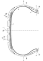
- FIG. 1 is a cross-sectional view of a meridian showing a pneumatic radial tire according to an embodiment of the present invention.
- the pneumatic tire of the present invention is arranged inside the tread portion 1, a pair of sidewall portions 2 arranged on both sides of the tread portion 1, and the sidewall portion 2 in the tire radial direction. It is provided with a pair of bead portions 3.
- reference numeral CL indicates the tire equator.
- FIG. 1 is a cross-sectional view of the meridian, it is not depicted, but the tread portion 1, the sidewall portion 2, and the bead portion 3 each extend in the tire circumferential direction to form an annular shape, whereby the toroidal of the pneumatic tire is formed.
- the basic structure of the shape is constructed.
- the description using FIG. 1 is basically based on the illustrated meridian cross-sectional shape, but all the tire constituent members extend in the tire circumferential direction to form an annular shape.
- a plurality of main grooves (4 in the illustrated example) extending in the tire circumferential direction are formed on the outer surface of the tread portion 1, but the number of main grooves is not particularly limited. Further, in addition to the main groove, various grooves and sipes including a lug groove extending in the tire width direction can be formed.
- a carcass layer 4 including a plurality of reinforcing cords extending in the tire radial direction is mounted between the pair of left and right bead portions 3.
- a bead core 5 is embedded in each bead portion, and a bead filler 6 having a substantially triangular cross section is arranged on the outer periphery of the bead core 5.
- the carcass layer 4 is folded around the bead core 5 from the inside to the outside in the tire width direction.
- the bead core 5 and the bead filler 6 are formed around the main body portion of the carcass layer 4 (the portion extending from the tread portion 1 to each bead portion 3 via each sidewall portion 2) and the folded portion (in each bead portion 3 around the bead core 5). It is wrapped by a portion that is folded back and extends toward each sidewall portion 2 side).
- a polyester cord is preferably used as the reinforcing cord of the carcass layer 4.
- each belt layer 7 includes a plurality of reinforcing cords that are inclined with respect to the tire circumferential direction, and the reinforcing cords are arranged so as to intersect each other between the layers.
- the inclination angle of the reinforcing cord with respect to the tire circumferential direction is set in the range of, for example, 10 ° to 40 °.
- a steel cord is preferably used as the reinforcing cord of the belt layer 7, for example.
- a belt cover layer 8 is provided on the outer peripheral side of the belt layer 7 for the purpose of improving high-speed durability and reducing road noise.
- the belt reinforcing layer 8 contains an organic fiber cord oriented in the tire circumferential direction.
- the angle of the organic fiber cord with respect to the tire circumferential direction is set to, for example, 0 ° to 5 °.
- the belt cover layer 8 always includes a full cover layer 8a that covers the entire area of the belt layer 7, and optionally includes a pair of edge cover layers 8b that locally cover both ends of the belt layer 7. (In the illustrated example, both the full cover layer 8a and the edge cover layer 8b are included).
- the belt cover layer 8 may be formed by spirally winding a strip material in which at least one organic fiber cord is aligned and coated with a coated rubber in the tire circumferential direction, and it is particularly desirable to have a jointless structure.
- the elastic modulus under a load of 2.0 cN / dtex at 100 ° C. is 3.5 cN / (tex ⁇ %) to 5.5 cN / (tex ⁇ %).
- Polyethylene terephthalate fiber cords (PET fiber cords) in the range are used.
- the elastic modulus of the PET fiber cord under a load of 2.0 cN / dtex at 100 ° C. exceeds 5.5 cN / (tex ⁇ %), the fatigue resistance of the cord is lowered and the durability of the tire is lowered.
- the elastic modulus [N / (tex ⁇ %)] under a 2.0 cN / dtex load at 100 ° C. conforms to JIS-L1017 “Chemical fiber tire cord test method” and has a grip interval of 250 mm.
- the cord tension in the tire is preferably 0.9 cN / dtex or more, more preferably 1.5 cN / dtex to 2.0 cN / dtex. It is good to be. By setting the cord tension in the tire in this way, heat generation can be suppressed and tire durability can be improved. If the cord tension of this organic fiber cord (PET fiber cord) in the tire is less than 0.9 cN / dtex, the peak of tan ⁇ rises, and the effect of improving the durability of the tire cannot be sufficiently obtained.
- the cord tension of the organic fiber cord (PET fiber cord) constituting the belt cover layer 8 in the tire shall be measured at least two laps inside the end of the strip material constituting the belt cover layer in the tire width direction. ..
- the PET fiber cord used as the organic fiber cord constituting the belt cover layer 8 preferably has a heat shrinkage stress of 0.6 cN / tex or more at 100 ° C.
- a heat shrinkage stress of 0.6 cN / tex or more at 100 ° C.
- the heat shrinkage stress (cN / tex) at 100 ° C. conforms to the "chemical fiber tire cord test method" of JIS-L1017, and has a sample length of 500 mm and a heating condition of 100 ° C. for 5 minutes. This is the heat shrinkage stress of the sample cord measured when heated in.
- the PET fiber cord is dipped with an adhesive, but in the normalization process after the two-bath treatment, the ambient temperature is set within the range of 210 ° C to 250 ° C, and the cord tension is applied. Is preferably set in the range of 2.2 ⁇ 10 ⁇ 2 N / tex to 6.7 ⁇ 10 ⁇ 2 N / tex. This makes it possible to impart the desired physical properties as described above to the PET fiber cord.
- the cord tension in the normalization process is smaller than 2.2 ⁇ 10 ⁇ 2 N / tex, the cord elastic modulus becomes low, and the medium frequency road noise cannot be sufficiently reduced, and conversely, 6.7 ⁇ 10 ⁇ If it is larger than 2 N / tex, the elastic modulus of the cord becomes high and the fatigue resistance of the cord decreases.
- the tread rubber layer 10 is arranged on the outer peripheral side of the above-mentioned tire constituent members (carcass layer 4, belt layer 7, belt cover layer 8).
- the tread rubber layer 10 has a structure in which two types of rubber layers having different physical properties (cap tread layer 11 and under tread layer 12) are laminated in the tire radial direction.
- the side rubber layer 20 is arranged on the outer peripheral side (outside in the tire width direction) of the carcass layer 4 in the sidewall portion 2, and the rim cushion rubber layer is arranged on the outer peripheral side (outside in the tire width direction) of the carcass layer 4 in the bead portion 3. 30 are arranged.
- the organic fiber cord (PET fiber cord) constituting the belt cover layer 8 described above is covered with a coated rubber (hereinafter referred to as a belt cover coated rubber).
- the rubber composition constituting the belt cover coat rubber always contains natural rubber as a rubber component, and styrene-butadiene rubber and / or butadiene rubber can be optionally used in combination.
- the natural rubber is contained in the rubber component in an amount of 50% by mass or more, preferably 60% by mass or more.
- the blending amount of natural rubber is 60% by mass to 80% by mass. %
- the blending amount of styrene-butadiene rubber may be 20% by mass to 40% by mass.
- the blending amount of the natural rubber is 50% by mass to 70% by mass
- the blending amount of the styrene-butadiene rubber is 10% by mass to 40% by mass
- the blending amount of the butadiene rubber is 5% by mass to 20% by mass.
- the natural rubber styrene-butadiene rubber, and butadiene rubber, those usually used for pneumatic tires (particularly, belt cover coat rubber) can be used.
- zinc oxide is always blended in the rubber composition constituting the belt cover coat rubber.
- the blending amount of zinc oxide is 5.0 parts by mass to 9.0 parts by mass, preferably 6.5 parts by mass to 8.5 parts by mass with respect to 100 parts by mass of the rubber component.
- the physical properties of the belt cover coat rubber are improved, which is advantageous for improving the durability of the tire. If the blending amount of zinc oxide is less than 5.0 parts by mass, it becomes difficult to secure sufficient hardness of the belt cover coat rubber. If the amount of zinc oxide compounded exceeds 9.0 parts by mass, the fatigue resistance may decrease.
- carbon black can be further added to the rubber composition constituting the belt cover coat rubber.
- the blending amount of carbon black is preferably 35 parts by mass to 65 parts by mass, and more preferably 40 parts by mass to 60 parts by mass with respect to 100 parts by mass of the rubber component. By blending carbon black in this way, hardness and strength can be increased, and it becomes possible to suitably use it for belt cover coat rubber. If the blending amount of carbon black is less than 35 parts by mass, it becomes difficult to sufficiently secure the hardness and strength of the belt cover coat rubber. If the amount of carbon black blended exceeds 65 parts by mass, the rolling resistance may deteriorate.
- the nitrogen adsorption specific surface area N 2 SA of carbon black is preferably 35 m 2 / g to 120 m 2 / g, and more preferably 40 m 2 / g to 90 m 2 / g.
- the hardness and strength of the belt cover coat rubber can be appropriately increased.
- the nitrogen adsorption specific surface area N 2 SA of carbon black is less than 35 m 2 / g, it becomes difficult to sufficiently secure the hardness and strength of the belt cover coat rubber.
- the nitrogen adsorption specific surface area N 2 SA of carbon black exceeds 120 m 2 / g, the rolling resistance may deteriorate.
- the nitrogen adsorption specific surface area N 2 SA of carbon black is measured according to JIS K6217-7.
- sulfur can be further added to the rubber composition constituting the belt cover coat rubber.
- the blending amount of sulfur is preferably 2.0 parts by mass to 3.5 parts by mass, and more preferably 2.3 parts by mass to 3.2 parts by mass with respect to 100 parts by mass of the rubber component.
- a vulcanization accelerator can be further added to the rubber composition constituting the belt cover coat rubber.
- the blending amount of the vulcanization accelerator is preferably 0.5 parts by mass to 2.0 parts by mass, and more preferably 0.7 parts by mass to 1.5 parts by mass with respect to 100 parts by mass of the rubber component.
- the belt cover coat rubber has the above-mentioned composition, and its breaking strength at 100 ° C. is preferably 10.0 MPa or more, more preferably 11 MPa or more, and further preferably 12 MPa or more.
- the elongation at break of the belt cover coat rubber at 100 ° C. is preferably 280% or more, more preferably 300% or more, still more preferably 330% or more.
- the modulus (M100) at 100% elongation is preferably 1.5 MPa to 3.5 MPa, more preferably 1.8 MPa to 3.2 MPa.
- the belt cover coat rubber becomes a physical property suitable for use in combination with the above-mentioned organic fiber cord (PET fiber cord), which is advantageous for improving the durability of the tire. ..
- the breaking strength is less than 10.0 MPa, it becomes difficult to sufficiently secure the durability.
- the elongation at break is less than 280%, it becomes difficult to sufficiently secure durability.
- the modulus (M100) at 100% extension is less than 1.5 MPa, the steering stability is lowered. If the modulus (M100) at the time of 100% elongation exceeds 3.5 MPa, the adhesiveness may decrease and the high-speed durability may deteriorate.
- the breaking strength, breaking elongation, and modulus (M100) at 100% elongation are measured using a No. 3 dumbbell under the conditions of a tensile speed of 500 mm / min and a temperature of 100 ° C. in accordance with JIS K6251. It was done.
- the belt cover coat rubber preferably has a storage elastic modulus E1 (100 ° C.) measured under the conditions of static strain 10%, dynamic strain ⁇ 2%, frequency 20 Hz, and temperature 100 ° C. in accordance with JIS K6394: 2007. Is 3.0 MPa or more and 6.0 MPa or less, more preferably 3.5 MPa to 5.5 MPa. By setting the storage elastic modulus in this way, high-speed durability can be improved. If the storage elastic modulus E1 (100 ° C.) deviates from the above range, it becomes difficult to satisfactorily exhibit high-speed durability.
- the elastic modulus is set for each of the organic fiber cord (PET fiber cord) and the belt cover cord rubber constituting the belt cover layer 8 as described above, but the organic fiber cord constituting the belt cover layer 8 (
- the elastic modulus of PET fiber cord) (elastic modulus under 2.0 cN / dtex load at 100 ° C.) is set to A, and the elastic modulus of the belt cover coated rubber (static strain 10%, dynamic strain ⁇ 2%, frequency 20 Hz, temperature 100).
- the storage elastic modulus E1 (100 ° C.) measured under the condition of ° C. is B
- these ratios A / B are preferably 0.6 to 1.6, more preferably 0.7 to 1.5. I hope there is.
- the ratio of free sulfur (sulfur atom remaining in a free state without participating in cross-linking after vulcanization) in the rubber is preferably 0.2% or less, more preferably. It is preferably 0.15% or less, more preferably 0.08% or less. By keeping the proportion of free sulfur low in this way, high-speed durability can be effectively improved. If the proportion of free sulfur exceeds 0.2%, the effect of improving high-speed durability may not be sufficiently obtained.
- the ratio of free sulfur shall be measured in accordance with JIS K6234.
- the organic fiber cord (PET fiber cord) having a tire size of 225 / 60R18 and having the basic structure illustrated in FIG. 1 and constituting the belt cover layer has an elastic modulus at 100 ° C. under a 2.0 cN / dtex load [ cN / (tex ⁇ %)], the cord tension [cN / dtex] in the tire is set as shown in Tables 1 and 2, and the coated rubber (belt) that coats the organic fiber cord (PET fiber cord).
- the belt cover layer has a jointless structure in which one organic fiber cord (PET fiber cord) is aligned and a strip formed by coating with coated rubber is spirally wound in the tire circumferential direction. ing.
- the cord driving density in the strip is 50 lines / 50 mm.
- each organic fiber cord (PET fiber cord) has a structure of 1100 dtex / 2.
- the elastic modulus [cN / (tex ⁇ %)] under a load of 2.0 cN / dtex at 100 ° C. conforms to JIS-L1017 “Chemical fiber tire cord test method”, grip interval 250 mm, tensile speed.
- the tensile test was carried out under the condition of 300 ⁇ 20 mm / min, and the calculation was made by converting the slope of the tangent line at the point corresponding to the load 2.0 cN / dtex of the load-elongation curve into the value per tex.
- the cord tension [cN / dtex] in the tire is obtained by removing the tread rubber from the tread portion to expose the belt cover layer, peeling the fiber cord from the predetermined length range of the belt cover layer, and the length after collection thereof.
- the amount of shrinkage with respect to the length before collection was determined. Specifically, the average value of the shrinkage amount was obtained for the five fiber cords located at the center of the outermost belt layer. Then, the load corresponding to the shrinkage amount (%) was obtained from the SS curve and measured by converting it into a value per 1 dtex.
- the rubber composition of each example is vulcanized at 180 ° C. for 5 minutes using a mold having a predetermined shape to prepare a sheet-shaped vulcanized rubber test piece having a thickness of 2 mm, and the following method is used. Measured at.
- dumbbell type JIS No. 3 test piece was prepared in accordance with JIS K6251, and a fully automatic tensile tester with a constant temperature bath, Strograph AR-T (manufactured by Toyo Seiki Seisakusho Co., Ltd.).
- the tensile test was carried out under the conditions of a tensile speed of 500 mm / min and a temperature of 100 ° C., and stress at break (break strength TB at 100 ° C (100 ° C) [MPa]) and elongation (break elongation EB at 100 ° C) ( 100 ° C.) [%]) was measured.
- the percentage of free sulfur [%] was measured using the sodium sulfite method described in JIS K6234.
- Each test tire is assembled to a wheel with a rim size of 18 x 7J, mounted as the front and rear wheels of a passenger car (front wheel drive vehicle) with a displacement of 2.5 L, the air pressure is set to 230 kPa, and the sound collecting microphone is inside the driver's seat window.
- the sound pressure level near the frequency of 315 Hz was measured when the test course composed of the asphalt road surface was run under the condition of an average speed of 50 km / h.
- the amount of change (dB) with respect to the standard was shown based on the conventional example.
- Each test tire was assembled on a wheel having a rim size of 18 ⁇ 7J, and stored in a chamber maintained at a temperature of 70 ° C. and a humidity of 95% in a state where oxygen was sealed at an internal pressure of 230 kPa for 30 days.
- the test tire thus pretreated was mounted on a drum tester equipped with a drum made of steel with a smooth surface and a diameter of 1707 mm, the ambient temperature was controlled to 38 ⁇ 3 ° C., and the speed was 120 km / h or 24 hours. Acceleration was performed by 10 km / h each time, and the mileage until the tire failed was measured.
- the evaluation result is shown by an index with the conventional example 1 as 100 using the measured value of the mileage. The larger the index value, the longer the mileage until a failure occurs, and the better the wet and heat durability.
- Dry heat durability Each test tire was assembled on a wheel having a rim size of 18 ⁇ 7J, filled with an oxygen pressure of 350 kPa, and stored in a gear oven at a temperature of 80 ° C. for 5 days.
- Such dry heat pretreated tires are filled with an air pressure of 230 kPa, mounted on an indoor drum tester (drum diameter 1707 mm), and after performing a high-speed durability test specified in JIS D4230, the tires continue to be 8 km every hour. Accelerate by / h and measure the mileage until the tire breaks down.
- the evaluation result is shown by an index with the conventional example 1 as 100 using the measured value of the mileage. The larger the index value, the longer the mileage until a failure occurs, and the better the dry heat durability.
- Nocrack 224 ⁇ Stearic acid NOF Corporation beads stearic acid NY ⁇
- Zinc white Zinc oxide 3 types manufactured by Shodo Chemical Industry Co., Ltd.
- Vulcanization accelerator NS-G manufactured by Sanshin Chemical Industry Co., Ltd.
- -Insoluble sulfur Shikoku Kasei Kogyo Co., Ltd.
- Mucron OT-20 sulfur content: 80% by mass
- the tires of Examples 1 to 13 reduce road noise and have wet heat durability, dry heat durability and high speed durability in comparison with the standard conventional example 1. Improved.
- the elastic modulus of the polyethylene terephthalate fiber cord constituting the belt cover layer under a load of 2.0 cN / dtex at 100 ° C. was high, and the blending amount of natural rubber and zinc oxide in the coated rubber was high. Due to the small amount, wet heat durability, dry heat durability, and high speed durability deteriorated.
- tread part 2 sidewall part 3 bead part 4 carcass layer 5 bead core 6 bead filler 7 belt layer 8 belt cover layer 8a full cover layer 8b edge cover layer 10 tread rubber layer 11 cap tread layer 12 under tread layer 20 side rubber layer 30 rim Cushion rubber layer CL tire tread
Landscapes
- Engineering & Computer Science (AREA)
- Mechanical Engineering (AREA)
- Textile Engineering (AREA)
- Chemical & Material Sciences (AREA)
- Health & Medical Sciences (AREA)
- Chemical Kinetics & Catalysis (AREA)
- Medicinal Chemistry (AREA)
- Polymers & Plastics (AREA)
- Organic Chemistry (AREA)
- Tires In General (AREA)
- Yarns And Mechanical Finishing Of Yarns Or Ropes (AREA)
Abstract
Description
各例の加硫ゴム試験片を用いて、JIS K6251に準拠して、ダンベル型JIS3号形試験片を作製し、恒温槽付き全自動引張り試験機 ストログラフAR‐T(東洋精機製作所社製)を用いて、引張り速度500mm/min、温度100℃の条件で引張り試験を行い、破断時の応力(100℃における破断強度TB(100℃)[MPa])と伸び(100℃における破断伸びEB(100℃)[%])を測定した。
各例の加硫ゴム試験片を用いて、JIS K6394:2007に準拠して、粘弾性スペクトロメータ(東洋精機製作所社製)を用いて、伸張変形歪率10%±2%、振動数20Hz、温度100℃の条件で、100℃における貯蔵弾性率E1(100℃)[MPa]を測定した。
各試験タイヤをリムサイズ18×7Jのホイールに組み付けて、排気量2.5Lの乗用車(前輪駆動車)の前後車輪として装着し、空気圧を230kPaとし、運転席の窓の内側に集音マイクを設置し、アスファルト路面からなるテストコースを平均速度50km/hの条件で走行させた際の周波数315Hz付近の音圧レベルを測定した。評価結果としては、従来例を基準とし、その基準に対する変化量(dB)を示した。
各試験タイヤをリムサイズ18×7Jのホイールに組み付け、内圧230kPaで酸素を封入した状態で温度70℃、湿度95%に保持されたチャンバー内に30日間保管した。このように前処理された試験タイヤを、表面が平滑な鋼製で直径1707mmのドラムを備えたドラム試験機に装着し、周辺温度を38±3℃に制御し、速度120km/hか24時間毎に10km/hずつ加速し、タイヤに故障が生じるまでの走行距離を計測した。評価結果は、走行距離の測定値を用い、従来例1を100とする指数にて示した。この指数値が大きいほど、故障が生じるまでの走行距離が長く、湿熱耐久性が優れていることを意味する。
各試験タイヤをリムサイズ18×7Jのホイールに組み付け、空気圧230kPaを充填し、室内ドラム試験機(ドラム径1707mm)に装着し、JIS D4230に規定される高速耐久性試験を実施した後、引き続き1時間毎に8km/hずつ加速し、タイヤに故障が生じるまでの走行距離を計測した。評価結果は、走行距離の測定値を用い、従来例1を100とする指数にて示した。この指数値が大きいほど、故障が生じるまでの走行距離が長く、湿熱耐久性が優れていることを意味する。
各試験タイヤをリムサイズ18×7Jのホイールに組み付け、酸素圧350kPaを充填し、温度80℃で5日間ギアオーブンで保管した。このような乾熱前処理したタイヤに空気圧230kPaを充填し、室内ドラム試験機(ドラム径1707mm)に装着し、JIS D4230に規定される高速耐久性試験を実施した後、引き続き1時間毎に8km/hずつ加速し、タイヤに故障が生じるまでの走行距離を計測した。評価結果は、走行距離の測定値を用い、従来例1を100とする指数にて示した。この指数値が大きいほど、故障が生じるまでの走行距離が長く、乾熱耐久性が優れていることを意味する。


・NR:天然ゴム、STR20
・SBR:スチレンブタジエンゴム、日本ゼオン社製 SBR1502
・CB1:カーボンブラック(HAF)、キャボットジャパン社製 ショウブラックN330
・CB2:カーボンブラック(GPF)、親日化カーボン社製 ニテロン#NG
・CB3:カーボンブラック(ISAF)、キャボットジャパン社製 ショウブラックN234
・アロマオイル:昭和シェル石油社製 エキストラクト4号
・老化防止剤:大内新興化学工業社製 ノクラック224
・ステアリン酸:日本油脂社製 ビーズステアリン酸NY
・亜鉛華:正同化学工業社製 酸化亜鉛3種
・加硫促進剤:三新化学工業社製 NS‐G
・不溶性硫黄:四国化成工業社製 ミュークロンOT‐20(硫黄含有量:80質量%)
2 サイドウォール部
3 ビード部
4 カーカス層
5 ビードコア
6 ビードフィラー
7 ベルト層
8 ベルトカバー層
8a フルカバー層
8b エッジカバー層
10 トレッドゴム層
11 キャップトレッド層
12 アンダートレッド層
20 サイドゴム層
30 リムクッションゴム層
CL タイヤ赤道
Claims (5)
- タイヤ周方向に延在して環状をなすトレッド部と、該トレッド部の両側に配置された一対のサイドウォール部と、これらサイドウォール部のタイヤ径方向内側に配置された一対のビード部とを備え、前記一対のビード部間に装架されたカーカス層と、前記トレッド部における前記カーカス層の外周側に配置された複数層のベルト層と、前記ベルト層の外周側に配置されたベルトカバー層とを有する空気入りタイヤにおいて、
前記ベルトカバー層はコートゴムで被覆された有機繊維コードをタイヤ周方向に沿って螺旋状に巻回することで構成され、前記有機繊維コードは100℃における2.0cN/dtex負荷時の弾性率が3.5cN/(tex・%)~5.5cN/(tex・%)の範囲にあるポリエチレンテレフタレート繊維コードであり、
前記コートゴムが、ゴム成分として天然ゴム、スチレンブタジエンゴム、ブタジエンゴムから選ばれる1種以上を含み、前記ゴム成分中の天然ゴムの配合量が50質量%以上であり、前記ゴム成分100質量部に対して亜鉛華が5.0質量部~9.0質量部配合されたゴム組成物からなることを特徴とする空気入りタイヤ。 - 前記有機繊維コードのタイヤ内におけるコード張力が0.9cN/dtex以上であることを特徴とする請求項1に記載の空気入りタイヤ。
- 前記コートゴムの100℃における破断強度が10.0MPa以上であり、前記コートゴムの100℃における破断伸びが280%以上であることを特徴とする請求項1または2に記載の空気入りタイヤ。
- 静歪10%、動歪±2%、周波数20Hz、温度100℃の条件で測定した前記コートゴムの貯蔵弾性率E1(100℃)が、3.0MPa≦E1(100℃)≦6.0MPaであることを特徴とする請求項1~3のいずれかに記載の空気入りタイヤ。
- 前記コートゴム中の遊離硫黄の割合が0.2%以下であることを特徴とする請求項1~4のいずれかに記載の空気入りタイヤ。
Priority Applications (3)
| Application Number | Priority Date | Filing Date | Title |
|---|---|---|---|
| CN202080055927.9A CN114206633B (zh) | 2019-08-08 | 2020-07-31 | 充气轮胎 |
| US17/633,056 US20220266632A1 (en) | 2019-08-08 | 2020-07-31 | Pneumatic tire |
| DE112020003164.0T DE112020003164B4 (de) | 2019-08-08 | 2020-07-31 | Luftreifen |
Applications Claiming Priority (2)
| Application Number | Priority Date | Filing Date | Title |
|---|---|---|---|
| JP2019-146322 | 2019-08-08 | ||
| JP2019146322A JP7103318B2 (ja) | 2019-08-08 | 2019-08-08 | 空気入りタイヤ |
Publications (1)
| Publication Number | Publication Date |
|---|---|
| WO2021024951A1 true WO2021024951A1 (ja) | 2021-02-11 |
Family
ID=74503824
Family Applications (1)
| Application Number | Title | Priority Date | Filing Date |
|---|---|---|---|
| PCT/JP2020/029509 Ceased WO2021024951A1 (ja) | 2019-08-08 | 2020-07-31 | 空気入りタイヤ |
Country Status (5)
| Country | Link |
|---|---|
| US (1) | US20220266632A1 (ja) |
| JP (1) | JP7103318B2 (ja) |
| CN (1) | CN114206633B (ja) |
| DE (1) | DE112020003164B4 (ja) |
| WO (1) | WO2021024951A1 (ja) |
Families Citing this family (5)
| Publication number | Priority date | Publication date | Assignee | Title |
|---|---|---|---|---|
| JP7211376B2 (ja) * | 2020-01-27 | 2023-01-24 | 横浜ゴム株式会社 | 空気入りタイヤ |
| JP6996592B2 (ja) * | 2020-06-23 | 2022-01-17 | 横浜ゴム株式会社 | 空気入りタイヤ |
| JP7744299B2 (ja) * | 2022-05-26 | 2025-09-25 | 株式会社ブリヂストン | タイヤ |
| JP2024041719A (ja) * | 2022-09-14 | 2024-03-27 | 住友ゴム工業株式会社 | タイヤ |
| WO2024180857A1 (ja) * | 2023-03-01 | 2024-09-06 | 株式会社ブリヂストン | タイヤ |
Citations (4)
| Publication number | Priority date | Publication date | Assignee | Title |
|---|---|---|---|---|
| JP2001063312A (ja) * | 1999-08-25 | 2001-03-13 | Bridgestone Corp | ラジアルタイヤ |
| JP2003220806A (ja) * | 2002-01-31 | 2003-08-05 | Yokohama Rubber Co Ltd:The | 空気入りタイヤおよびその製造方法 |
| JP2005112065A (ja) * | 2003-10-06 | 2005-04-28 | Bridgestone Corp | 空気入りラジアルタイヤ |
| JP2014108675A (ja) * | 2012-11-30 | 2014-06-12 | Toyo Tire & Rubber Co Ltd | 空気入りラジアルタイヤ |
Family Cites Families (11)
| Publication number | Priority date | Publication date | Assignee | Title |
|---|---|---|---|---|
| JP3555809B2 (ja) * | 1995-06-19 | 2004-08-18 | 株式会社ブリヂストン | ラジアルタイヤ |
| US6026878A (en) * | 1997-05-29 | 2000-02-22 | The Goodyear Tire & Rubber Company | Inextensible high temperature resistant tire |
| JP2003019762A (ja) * | 2001-07-06 | 2003-01-21 | Sumitomo Rubber Ind Ltd | 空気入りラジアルタイヤの製造方法及びそれにより製造された空気入りラジアルタイヤ |
| US20060169382A1 (en) * | 2005-01-28 | 2006-08-03 | Sandstrom Paul H | Tire with internal cord reinforced rubber component |
| JP5668323B2 (ja) * | 2010-05-13 | 2015-02-12 | 横浜ゴム株式会社 | 新都市交通車両用空気入りラジアルタイヤ |
| JP5395882B2 (ja) * | 2011-12-01 | 2014-01-22 | 住友ゴム工業株式会社 | 空気入りタイヤ |
| EP3030431B1 (en) * | 2013-08-08 | 2019-03-27 | Pirelli Tyre S.p.A. | Method for increasing the performances of a tyres for vehicle wheels and tyre for vehicle wheels |
| JP7151217B2 (ja) * | 2018-07-03 | 2022-10-12 | 横浜ゴム株式会社 | 空気入りラジアルタイヤ |
| JP7139752B2 (ja) * | 2018-07-24 | 2022-09-21 | 横浜ゴム株式会社 | 空気入りラジアルタイヤ |
| JP6809548B2 (ja) * | 2019-02-07 | 2021-01-06 | 横浜ゴム株式会社 | 空気入りラジアルタイヤ |
| JP7553765B2 (ja) * | 2020-04-10 | 2024-09-19 | 横浜ゴム株式会社 | 空気入りタイヤ |
-
2019
- 2019-08-08 JP JP2019146322A patent/JP7103318B2/ja active Active
-
2020
- 2020-07-31 WO PCT/JP2020/029509 patent/WO2021024951A1/ja not_active Ceased
- 2020-07-31 CN CN202080055927.9A patent/CN114206633B/zh active Active
- 2020-07-31 DE DE112020003164.0T patent/DE112020003164B4/de active Active
- 2020-07-31 US US17/633,056 patent/US20220266632A1/en not_active Abandoned
Patent Citations (4)
| Publication number | Priority date | Publication date | Assignee | Title |
|---|---|---|---|---|
| JP2001063312A (ja) * | 1999-08-25 | 2001-03-13 | Bridgestone Corp | ラジアルタイヤ |
| JP2003220806A (ja) * | 2002-01-31 | 2003-08-05 | Yokohama Rubber Co Ltd:The | 空気入りタイヤおよびその製造方法 |
| JP2005112065A (ja) * | 2003-10-06 | 2005-04-28 | Bridgestone Corp | 空気入りラジアルタイヤ |
| JP2014108675A (ja) * | 2012-11-30 | 2014-06-12 | Toyo Tire & Rubber Co Ltd | 空気入りラジアルタイヤ |
Also Published As
| Publication number | Publication date |
|---|---|
| JP7103318B2 (ja) | 2022-07-20 |
| DE112020003164T5 (de) | 2022-03-17 |
| CN114206633A (zh) | 2022-03-18 |
| DE112020003164B4 (de) | 2026-01-08 |
| JP2021024510A (ja) | 2021-02-22 |
| US20220266632A1 (en) | 2022-08-25 |
| CN114206633B (zh) | 2023-11-03 |
Similar Documents
| Publication | Publication Date | Title |
|---|---|---|
| JP7103318B2 (ja) | 空気入りタイヤ | |
| JP2021024509A (ja) | 空気入りタイヤ | |
| JP4316660B2 (ja) | 空気入りタイヤ | |
| JP7553765B2 (ja) | 空気入りタイヤ | |
| JP5200690B2 (ja) | 空気入りタイヤ | |
| JPS584642B2 (ja) | ラジアルタイヤ | |
| WO2020162597A1 (ja) | 空気入りラジアルタイヤ | |
| JP2001180225A (ja) | ラジアルタイヤ | |
| JP2010179689A (ja) | 空気入りラジアルタイヤ | |
| JP2020066394A (ja) | 空気入りラジアルタイヤ | |
| JPH11286203A (ja) | 空気入りタイヤ | |
| JP2019006279A (ja) | 帯状部材、及び空気入りタイヤ | |
| EP4134247A1 (en) | Pneumatic tire | |
| US20230065888A1 (en) | Pneumatic tire | |
| JP4428098B2 (ja) | 乗用車用空気入りラジアルタイヤ | |
| JP6996592B2 (ja) | 空気入りタイヤ | |
| JP6988865B2 (ja) | 空気入りタイヤ | |
| JP4188406B1 (ja) | 空気入りタイヤ | |
| CN113498444B (zh) | 充气子午线轮胎 | |
| JP2001018614A (ja) | 空気入りタイヤ | |
| JP2020066393A (ja) | 空気入りラジアルタイヤ | |
| JP7801654B2 (ja) | タイヤ | |
| JP3387571B2 (ja) | 空気入りラジアルタイヤ | |
| CN111819090A (zh) | 充气轮胎 | |
| JP2022156283A (ja) | 空気入りタイヤおよびその製造方法 |
Legal Events
| Date | Code | Title | Description |
|---|---|---|---|
| 121 | Ep: the epo has been informed by wipo that ep was designated in this application |
Ref document number: 20849846 Country of ref document: EP Kind code of ref document: A1 |
|
| WWE | Wipo information: entry into national phase |
Ref document number: 112020003164 Country of ref document: DE |
|
| WWP | Wipo information: published in national office |
Ref document number: 112020003164 Country of ref document: DE |
|
| 122 | Ep: pct application non-entry in european phase |
Ref document number: 20849846 Country of ref document: EP Kind code of ref document: A1 |
|
| WWG | Wipo information: grant in national office |
Ref document number: 112020003164 Country of ref document: DE |