WO2021006350A1 - 金属端子用接着性フィルム、金属端子用接着性フィルム付き金属端子、当該金属端子用接着性フィルムを用いた蓄電デバイス、及び蓄電デバイスの製造方法 - Google Patents
金属端子用接着性フィルム、金属端子用接着性フィルム付き金属端子、当該金属端子用接着性フィルムを用いた蓄電デバイス、及び蓄電デバイスの製造方法 Download PDFInfo
- Publication number
- WO2021006350A1 WO2021006350A1 PCT/JP2020/027120 JP2020027120W WO2021006350A1 WO 2021006350 A1 WO2021006350 A1 WO 2021006350A1 JP 2020027120 W JP2020027120 W JP 2020027120W WO 2021006350 A1 WO2021006350 A1 WO 2021006350A1
- Authority
- WO
- WIPO (PCT)
- Prior art keywords
- adhesive film
- metal terminals
- power storage
- storage device
- layer
- Prior art date
- Legal status (The legal status is an assumption and is not a legal conclusion. Google has not performed a legal analysis and makes no representation as to the accuracy of the status listed.)
- Ceased
Links
Images




Classifications
-
- C—CHEMISTRY; METALLURGY
- C09—DYES; PAINTS; POLISHES; NATURAL RESINS; ADHESIVES; COMPOSITIONS NOT OTHERWISE PROVIDED FOR; APPLICATIONS OF MATERIALS NOT OTHERWISE PROVIDED FOR
- C09J—ADHESIVES; NON-MECHANICAL ASPECTS OF ADHESIVE PROCESSES IN GENERAL; ADHESIVE PROCESSES NOT PROVIDED FOR ELSEWHERE; USE OF MATERIALS AS ADHESIVES
- C09J7/00—Adhesives in the form of films or foils
- C09J7/30—Adhesives in the form of films or foils characterised by the adhesive composition
-
- C—CHEMISTRY; METALLURGY
- C09—DYES; PAINTS; POLISHES; NATURAL RESINS; ADHESIVES; COMPOSITIONS NOT OTHERWISE PROVIDED FOR; APPLICATIONS OF MATERIALS NOT OTHERWISE PROVIDED FOR
- C09J—ADHESIVES; NON-MECHANICAL ASPECTS OF ADHESIVE PROCESSES IN GENERAL; ADHESIVE PROCESSES NOT PROVIDED FOR ELSEWHERE; USE OF MATERIALS AS ADHESIVES
- C09J7/00—Adhesives in the form of films or foils
- C09J7/20—Adhesives in the form of films or foils characterised by their carriers
- C09J7/22—Plastics; Metallised plastics
- C09J7/24—Plastics; Metallised plastics based on macromolecular compounds obtained by reactions involving only carbon-to-carbon unsaturated bonds
- C09J7/241—Polyolefin, e.g.rubber
- C09J7/243—Ethylene or propylene polymers
-
- B—PERFORMING OPERATIONS; TRANSPORTING
- B32—LAYERED PRODUCTS
- B32B—LAYERED PRODUCTS, i.e. PRODUCTS BUILT-UP OF STRATA OF FLAT OR NON-FLAT, e.g. CELLULAR OR HONEYCOMB, FORM
- B32B15/00—Layered products comprising a layer of metal
- B32B15/04—Layered products comprising a layer of metal comprising metal as the main or only constituent of a layer, which is next to another layer of the same or of a different material
- B32B15/08—Layered products comprising a layer of metal comprising metal as the main or only constituent of a layer, which is next to another layer of the same or of a different material of synthetic resin
- B32B15/085—Layered products comprising a layer of metal comprising metal as the main or only constituent of a layer, which is next to another layer of the same or of a different material of synthetic resin comprising polyolefins
-
- B—PERFORMING OPERATIONS; TRANSPORTING
- B32—LAYERED PRODUCTS
- B32B—LAYERED PRODUCTS, i.e. PRODUCTS BUILT-UP OF STRATA OF FLAT OR NON-FLAT, e.g. CELLULAR OR HONEYCOMB, FORM
- B32B15/00—Layered products comprising a layer of metal
- B32B15/04—Layered products comprising a layer of metal comprising metal as the main or only constituent of a layer, which is next to another layer of the same or of a different material
- B32B15/08—Layered products comprising a layer of metal comprising metal as the main or only constituent of a layer, which is next to another layer of the same or of a different material of synthetic resin
- B32B15/088—Layered products comprising a layer of metal comprising metal as the main or only constituent of a layer, which is next to another layer of the same or of a different material of synthetic resin comprising polyamides
-
- B—PERFORMING OPERATIONS; TRANSPORTING
- B32—LAYERED PRODUCTS
- B32B—LAYERED PRODUCTS, i.e. PRODUCTS BUILT-UP OF STRATA OF FLAT OR NON-FLAT, e.g. CELLULAR OR HONEYCOMB, FORM
- B32B15/00—Layered products comprising a layer of metal
- B32B15/20—Layered products comprising a layer of metal comprising aluminium or copper
-
- B—PERFORMING OPERATIONS; TRANSPORTING
- B32—LAYERED PRODUCTS
- B32B—LAYERED PRODUCTS, i.e. PRODUCTS BUILT-UP OF STRATA OF FLAT OR NON-FLAT, e.g. CELLULAR OR HONEYCOMB, FORM
- B32B27/00—Layered products comprising a layer of synthetic resin
- B32B27/06—Layered products comprising a layer of synthetic resin as the main or only constituent of a layer, which is next to another layer of the same or of a different material
- B32B27/08—Layered products comprising a layer of synthetic resin as the main or only constituent of a layer, which is next to another layer of the same or of a different material of synthetic resin
-
- B—PERFORMING OPERATIONS; TRANSPORTING
- B32—LAYERED PRODUCTS
- B32B—LAYERED PRODUCTS, i.e. PRODUCTS BUILT-UP OF STRATA OF FLAT OR NON-FLAT, e.g. CELLULAR OR HONEYCOMB, FORM
- B32B27/00—Layered products comprising a layer of synthetic resin
- B32B27/32—Layered products comprising a layer of synthetic resin comprising polyolefins
-
- B—PERFORMING OPERATIONS; TRANSPORTING
- B32—LAYERED PRODUCTS
- B32B—LAYERED PRODUCTS, i.e. PRODUCTS BUILT-UP OF STRATA OF FLAT OR NON-FLAT, e.g. CELLULAR OR HONEYCOMB, FORM
- B32B37/00—Methods or apparatus for laminating, e.g. by curing or by ultrasonic bonding
- B32B37/04—Methods or apparatus for laminating, e.g. by curing or by ultrasonic bonding characterised by the partial melting of at least one layer
-
- B—PERFORMING OPERATIONS; TRANSPORTING
- B32—LAYERED PRODUCTS
- B32B—LAYERED PRODUCTS, i.e. PRODUCTS BUILT-UP OF STRATA OF FLAT OR NON-FLAT, e.g. CELLULAR OR HONEYCOMB, FORM
- B32B7/00—Layered products characterised by the relation between layers; Layered products characterised by the relative orientation of features between layers, or by the relative values of a measurable parameter between layers, i.e. products comprising layers having different physical, chemical or physicochemical properties; Layered products characterised by the interconnection of layers
- B32B7/02—Physical, chemical or physicochemical properties
- B32B7/027—Thermal properties
- B32B7/028—Heat-shrinkability
-
- B—PERFORMING OPERATIONS; TRANSPORTING
- B32—LAYERED PRODUCTS
- B32B—LAYERED PRODUCTS, i.e. PRODUCTS BUILT-UP OF STRATA OF FLAT OR NON-FLAT, e.g. CELLULAR OR HONEYCOMB, FORM
- B32B7/00—Layered products characterised by the relation between layers; Layered products characterised by the relative orientation of features between layers, or by the relative values of a measurable parameter between layers, i.e. products comprising layers having different physical, chemical or physicochemical properties; Layered products characterised by the interconnection of layers
- B32B7/04—Interconnection of layers
- B32B7/12—Interconnection of layers using interposed adhesives or interposed materials with bonding properties
-
- H—ELECTRICITY
- H01—ELECTRIC ELEMENTS
- H01G—CAPACITORS; CAPACITORS, RECTIFIERS, DETECTORS, SWITCHING DEVICES, LIGHT-SENSITIVE OR TEMPERATURE-SENSITIVE DEVICES OF THE ELECTROLYTIC TYPE
- H01G11/00—Hybrid capacitors, i.e. capacitors having different positive and negative electrodes; Electric double-layer [EDL] capacitors; Processes for the manufacture thereof or of parts thereof
- H01G11/74—Terminals, e.g. extensions of current collectors
-
- H—ELECTRICITY
- H01—ELECTRIC ELEMENTS
- H01G—CAPACITORS; CAPACITORS, RECTIFIERS, DETECTORS, SWITCHING DEVICES, LIGHT-SENSITIVE OR TEMPERATURE-SENSITIVE DEVICES OF THE ELECTROLYTIC TYPE
- H01G11/00—Hybrid capacitors, i.e. capacitors having different positive and negative electrodes; Electric double-layer [EDL] capacitors; Processes for the manufacture thereof or of parts thereof
- H01G11/78—Cases; Housings; Encapsulations; Mountings
- H01G11/80—Gaskets; Sealings
-
- H—ELECTRICITY
- H01—ELECTRIC ELEMENTS
- H01G—CAPACITORS; CAPACITORS, RECTIFIERS, DETECTORS, SWITCHING DEVICES, LIGHT-SENSITIVE OR TEMPERATURE-SENSITIVE DEVICES OF THE ELECTROLYTIC TYPE
- H01G11/00—Hybrid capacitors, i.e. capacitors having different positive and negative electrodes; Electric double-layer [EDL] capacitors; Processes for the manufacture thereof or of parts thereof
- H01G11/78—Cases; Housings; Encapsulations; Mountings
- H01G11/82—Fixing or assembling a capacitive element in a housing, e.g. mounting electrodes, current collectors or terminals in containers or encapsulations
-
- H—ELECTRICITY
- H01—ELECTRIC ELEMENTS
- H01G—CAPACITORS; CAPACITORS, RECTIFIERS, DETECTORS, SWITCHING DEVICES, LIGHT-SENSITIVE OR TEMPERATURE-SENSITIVE DEVICES OF THE ELECTROLYTIC TYPE
- H01G2/00—Details of capacitors not covered by a single one of groups H01G4/00-H01G11/00
- H01G2/10—Housing; Encapsulation
- H01G2/103—Sealings, e.g. for lead-in wires; Covers
-
- H—ELECTRICITY
- H01—ELECTRIC ELEMENTS
- H01G—CAPACITORS; CAPACITORS, RECTIFIERS, DETECTORS, SWITCHING DEVICES, LIGHT-SENSITIVE OR TEMPERATURE-SENSITIVE DEVICES OF THE ELECTROLYTIC TYPE
- H01G9/00—Electrolytic capacitors, rectifiers, detectors, switching devices, light-sensitive or temperature-sensitive devices; Processes of their manufacture
- H01G9/004—Details
- H01G9/08—Housing; Encapsulation
- H01G9/10—Sealing, e.g. of lead-in wires
-
- H—ELECTRICITY
- H01—ELECTRIC ELEMENTS
- H01M—PROCESSES OR MEANS, e.g. BATTERIES, FOR THE DIRECT CONVERSION OF CHEMICAL ENERGY INTO ELECTRICAL ENERGY
- H01M50/00—Constructional details or processes of manufacture of the non-active parts of electrochemical cells other than fuel cells, e.g. hybrid cells
- H01M50/10—Primary casings; Jackets or wrappings
- H01M50/116—Primary casings; Jackets or wrappings characterised by the material
- H01M50/121—Organic material
-
- H—ELECTRICITY
- H01—ELECTRIC ELEMENTS
- H01M—PROCESSES OR MEANS, e.g. BATTERIES, FOR THE DIRECT CONVERSION OF CHEMICAL ENERGY INTO ELECTRICAL ENERGY
- H01M50/00—Constructional details or processes of manufacture of the non-active parts of electrochemical cells other than fuel cells, e.g. hybrid cells
- H01M50/10—Primary casings; Jackets or wrappings
- H01M50/116—Primary casings; Jackets or wrappings characterised by the material
- H01M50/124—Primary casings; Jackets or wrappings characterised by the material having a layered structure
-
- H—ELECTRICITY
- H01—ELECTRIC ELEMENTS
- H01M—PROCESSES OR MEANS, e.g. BATTERIES, FOR THE DIRECT CONVERSION OF CHEMICAL ENERGY INTO ELECTRICAL ENERGY
- H01M50/00—Constructional details or processes of manufacture of the non-active parts of electrochemical cells other than fuel cells, e.g. hybrid cells
- H01M50/10—Primary casings; Jackets or wrappings
- H01M50/116—Primary casings; Jackets or wrappings characterised by the material
- H01M50/124—Primary casings; Jackets or wrappings characterised by the material having a layered structure
- H01M50/126—Primary casings; Jackets or wrappings characterised by the material having a layered structure comprising three or more layers
-
- H—ELECTRICITY
- H01—ELECTRIC ELEMENTS
- H01M—PROCESSES OR MEANS, e.g. BATTERIES, FOR THE DIRECT CONVERSION OF CHEMICAL ENERGY INTO ELECTRICAL ENERGY
- H01M50/00—Constructional details or processes of manufacture of the non-active parts of electrochemical cells other than fuel cells, e.g. hybrid cells
- H01M50/10—Primary casings; Jackets or wrappings
- H01M50/116—Primary casings; Jackets or wrappings characterised by the material
- H01M50/124—Primary casings; Jackets or wrappings characterised by the material having a layered structure
- H01M50/126—Primary casings; Jackets or wrappings characterised by the material having a layered structure comprising three or more layers
- H01M50/129—Primary casings; Jackets or wrappings characterised by the material having a layered structure comprising three or more layers with two or more layers of only organic material
-
- H—ELECTRICITY
- H01—ELECTRIC ELEMENTS
- H01M—PROCESSES OR MEANS, e.g. BATTERIES, FOR THE DIRECT CONVERSION OF CHEMICAL ENERGY INTO ELECTRICAL ENERGY
- H01M50/00—Constructional details or processes of manufacture of the non-active parts of electrochemical cells other than fuel cells, e.g. hybrid cells
- H01M50/10—Primary casings; Jackets or wrappings
- H01M50/183—Sealing members
- H01M50/19—Sealing members characterised by the material
- H01M50/198—Sealing members characterised by the material characterised by physical properties, e.g. adhesiveness or hardness
-
- H—ELECTRICITY
- H01—ELECTRIC ELEMENTS
- H01M—PROCESSES OR MEANS, e.g. BATTERIES, FOR THE DIRECT CONVERSION OF CHEMICAL ENERGY INTO ELECTRICAL ENERGY
- H01M50/00—Constructional details or processes of manufacture of the non-active parts of electrochemical cells other than fuel cells, e.g. hybrid cells
- H01M50/50—Current conducting connections for cells or batteries
- H01M50/543—Terminals
-
- H—ELECTRICITY
- H01—ELECTRIC ELEMENTS
- H01M—PROCESSES OR MEANS, e.g. BATTERIES, FOR THE DIRECT CONVERSION OF CHEMICAL ENERGY INTO ELECTRICAL ENERGY
- H01M50/00—Constructional details or processes of manufacture of the non-active parts of electrochemical cells other than fuel cells, e.g. hybrid cells
- H01M50/50—Current conducting connections for cells or batteries
- H01M50/543—Terminals
- H01M50/552—Terminals characterised by their shape
- H01M50/553—Terminals adapted for prismatic, pouch or rectangular cells
- H01M50/557—Plate-shaped terminals
-
- H—ELECTRICITY
- H01—ELECTRIC ELEMENTS
- H01M—PROCESSES OR MEANS, e.g. BATTERIES, FOR THE DIRECT CONVERSION OF CHEMICAL ENERGY INTO ELECTRICAL ENERGY
- H01M50/00—Constructional details or processes of manufacture of the non-active parts of electrochemical cells other than fuel cells, e.g. hybrid cells
- H01M50/50—Current conducting connections for cells or batteries
- H01M50/572—Means for preventing undesired use or discharge
- H01M50/584—Means for preventing undesired use or discharge for preventing incorrect connections inside or outside the batteries
- H01M50/588—Means for preventing undesired use or discharge for preventing incorrect connections inside or outside the batteries outside the batteries, e.g. incorrect connections of terminals or busbars
-
- H—ELECTRICITY
- H01—ELECTRIC ELEMENTS
- H01M—PROCESSES OR MEANS, e.g. BATTERIES, FOR THE DIRECT CONVERSION OF CHEMICAL ENERGY INTO ELECTRICAL ENERGY
- H01M50/00—Constructional details or processes of manufacture of the non-active parts of electrochemical cells other than fuel cells, e.g. hybrid cells
- H01M50/50—Current conducting connections for cells or batteries
- H01M50/572—Means for preventing undesired use or discharge
- H01M50/584—Means for preventing undesired use or discharge for preventing incorrect connections inside or outside the batteries
- H01M50/59—Means for preventing undesired use or discharge for preventing incorrect connections inside or outside the batteries characterised by the protection means
- H01M50/595—Tapes
-
- B—PERFORMING OPERATIONS; TRANSPORTING
- B32—LAYERED PRODUCTS
- B32B—LAYERED PRODUCTS, i.e. PRODUCTS BUILT-UP OF STRATA OF FLAT OR NON-FLAT, e.g. CELLULAR OR HONEYCOMB, FORM
- B32B2250/00—Layers arrangement
- B32B2250/24—All layers being polymeric
- B32B2250/242—All polymers belonging to those covered by group B32B27/32
-
- B—PERFORMING OPERATIONS; TRANSPORTING
- B32—LAYERED PRODUCTS
- B32B—LAYERED PRODUCTS, i.e. PRODUCTS BUILT-UP OF STRATA OF FLAT OR NON-FLAT, e.g. CELLULAR OR HONEYCOMB, FORM
- B32B2250/00—Layers arrangement
- B32B2250/40—Symmetrical or sandwich layers, e.g. ABA, ABCBA, ABCCBA
-
- B—PERFORMING OPERATIONS; TRANSPORTING
- B32—LAYERED PRODUCTS
- B32B—LAYERED PRODUCTS, i.e. PRODUCTS BUILT-UP OF STRATA OF FLAT OR NON-FLAT, e.g. CELLULAR OR HONEYCOMB, FORM
- B32B2307/00—Properties of the layers or laminate
- B32B2307/20—Properties of the layers or laminate having particular electrical or magnetic properties, e.g. piezoelectric
- B32B2307/206—Insulating
-
- B—PERFORMING OPERATIONS; TRANSPORTING
- B32—LAYERED PRODUCTS
- B32B—LAYERED PRODUCTS, i.e. PRODUCTS BUILT-UP OF STRATA OF FLAT OR NON-FLAT, e.g. CELLULAR OR HONEYCOMB, FORM
- B32B2307/00—Properties of the layers or laminate
- B32B2307/30—Properties of the layers or laminate having particular thermal properties
-
- B—PERFORMING OPERATIONS; TRANSPORTING
- B32—LAYERED PRODUCTS
- B32B—LAYERED PRODUCTS, i.e. PRODUCTS BUILT-UP OF STRATA OF FLAT OR NON-FLAT, e.g. CELLULAR OR HONEYCOMB, FORM
- B32B2307/00—Properties of the layers or laminate
- B32B2307/30—Properties of the layers or laminate having particular thermal properties
- B32B2307/31—Heat sealable
-
- B—PERFORMING OPERATIONS; TRANSPORTING
- B32—LAYERED PRODUCTS
- B32B—LAYERED PRODUCTS, i.e. PRODUCTS BUILT-UP OF STRATA OF FLAT OR NON-FLAT, e.g. CELLULAR OR HONEYCOMB, FORM
- B32B2307/00—Properties of the layers or laminate
- B32B2307/50—Properties of the layers or laminate having particular mechanical properties
- B32B2307/54—Yield strength; Tensile strength
-
- B—PERFORMING OPERATIONS; TRANSPORTING
- B32—LAYERED PRODUCTS
- B32B—LAYERED PRODUCTS, i.e. PRODUCTS BUILT-UP OF STRATA OF FLAT OR NON-FLAT, e.g. CELLULAR OR HONEYCOMB, FORM
- B32B2307/00—Properties of the layers or laminate
- B32B2307/50—Properties of the layers or laminate having particular mechanical properties
- B32B2307/546—Flexural strength; Flexion stiffness
-
- B—PERFORMING OPERATIONS; TRANSPORTING
- B32—LAYERED PRODUCTS
- B32B—LAYERED PRODUCTS, i.e. PRODUCTS BUILT-UP OF STRATA OF FLAT OR NON-FLAT, e.g. CELLULAR OR HONEYCOMB, FORM
- B32B2307/00—Properties of the layers or laminate
- B32B2307/50—Properties of the layers or laminate having particular mechanical properties
- B32B2307/558—Impact strength, toughness
-
- B—PERFORMING OPERATIONS; TRANSPORTING
- B32—LAYERED PRODUCTS
- B32B—LAYERED PRODUCTS, i.e. PRODUCTS BUILT-UP OF STRATA OF FLAT OR NON-FLAT, e.g. CELLULAR OR HONEYCOMB, FORM
- B32B2307/00—Properties of the layers or laminate
- B32B2307/50—Properties of the layers or laminate having particular mechanical properties
- B32B2307/56—Damping, energy absorption
-
- B—PERFORMING OPERATIONS; TRANSPORTING
- B32—LAYERED PRODUCTS
- B32B—LAYERED PRODUCTS, i.e. PRODUCTS BUILT-UP OF STRATA OF FLAT OR NON-FLAT, e.g. CELLULAR OR HONEYCOMB, FORM
- B32B2307/00—Properties of the layers or laminate
- B32B2307/70—Other properties
- B32B2307/724—Permeability to gases, adsorption
- B32B2307/7242—Non-permeable
- B32B2307/7246—Water vapor barrier
-
- B—PERFORMING OPERATIONS; TRANSPORTING
- B32—LAYERED PRODUCTS
- B32B—LAYERED PRODUCTS, i.e. PRODUCTS BUILT-UP OF STRATA OF FLAT OR NON-FLAT, e.g. CELLULAR OR HONEYCOMB, FORM
- B32B2307/00—Properties of the layers or laminate
- B32B2307/70—Other properties
- B32B2307/732—Dimensional properties
-
- B—PERFORMING OPERATIONS; TRANSPORTING
- B32—LAYERED PRODUCTS
- B32B—LAYERED PRODUCTS, i.e. PRODUCTS BUILT-UP OF STRATA OF FLAT OR NON-FLAT, e.g. CELLULAR OR HONEYCOMB, FORM
- B32B2307/00—Properties of the layers or laminate
- B32B2307/70—Other properties
- B32B2307/732—Dimensional properties
- B32B2307/734—Dimensional stability
-
- B—PERFORMING OPERATIONS; TRANSPORTING
- B32—LAYERED PRODUCTS
- B32B—LAYERED PRODUCTS, i.e. PRODUCTS BUILT-UP OF STRATA OF FLAT OR NON-FLAT, e.g. CELLULAR OR HONEYCOMB, FORM
- B32B2410/00—Agriculture-related articles
-
- B—PERFORMING OPERATIONS; TRANSPORTING
- B32—LAYERED PRODUCTS
- B32B—LAYERED PRODUCTS, i.e. PRODUCTS BUILT-UP OF STRATA OF FLAT OR NON-FLAT, e.g. CELLULAR OR HONEYCOMB, FORM
- B32B2457/00—Electrical equipment
- B32B2457/10—Batteries
-
- B—PERFORMING OPERATIONS; TRANSPORTING
- B32—LAYERED PRODUCTS
- B32B—LAYERED PRODUCTS, i.e. PRODUCTS BUILT-UP OF STRATA OF FLAT OR NON-FLAT, e.g. CELLULAR OR HONEYCOMB, FORM
- B32B2457/00—Electrical equipment
- B32B2457/16—Capacitors
-
- B—PERFORMING OPERATIONS; TRANSPORTING
- B32—LAYERED PRODUCTS
- B32B—LAYERED PRODUCTS, i.e. PRODUCTS BUILT-UP OF STRATA OF FLAT OR NON-FLAT, e.g. CELLULAR OR HONEYCOMB, FORM
- B32B2553/00—Packaging equipment or accessories not otherwise provided for
-
- C—CHEMISTRY; METALLURGY
- C09—DYES; PAINTS; POLISHES; NATURAL RESINS; ADHESIVES; COMPOSITIONS NOT OTHERWISE PROVIDED FOR; APPLICATIONS OF MATERIALS NOT OTHERWISE PROVIDED FOR
- C09J—ADHESIVES; NON-MECHANICAL ASPECTS OF ADHESIVE PROCESSES IN GENERAL; ADHESIVE PROCESSES NOT PROVIDED FOR ELSEWHERE; USE OF MATERIALS AS ADHESIVES
- C09J2203/00—Applications of adhesives in processes or use of adhesives in the form of films or foils
- C09J2203/326—Applications of adhesives in processes or use of adhesives in the form of films or foils for bonding electronic components such as wafers, chips or semiconductors
-
- C—CHEMISTRY; METALLURGY
- C09—DYES; PAINTS; POLISHES; NATURAL RESINS; ADHESIVES; COMPOSITIONS NOT OTHERWISE PROVIDED FOR; APPLICATIONS OF MATERIALS NOT OTHERWISE PROVIDED FOR
- C09J—ADHESIVES; NON-MECHANICAL ASPECTS OF ADHESIVE PROCESSES IN GENERAL; ADHESIVE PROCESSES NOT PROVIDED FOR ELSEWHERE; USE OF MATERIALS AS ADHESIVES
- C09J2203/00—Applications of adhesives in processes or use of adhesives in the form of films or foils
- C09J2203/33—Applications of adhesives in processes or use of adhesives in the form of films or foils for batteries or fuel cells
-
- C—CHEMISTRY; METALLURGY
- C09—DYES; PAINTS; POLISHES; NATURAL RESINS; ADHESIVES; COMPOSITIONS NOT OTHERWISE PROVIDED FOR; APPLICATIONS OF MATERIALS NOT OTHERWISE PROVIDED FOR
- C09J—ADHESIVES; NON-MECHANICAL ASPECTS OF ADHESIVE PROCESSES IN GENERAL; ADHESIVE PROCESSES NOT PROVIDED FOR ELSEWHERE; USE OF MATERIALS AS ADHESIVES
- C09J2301/00—Additional features of adhesives in the form of films or foils
- C09J2301/10—Additional features of adhesives in the form of films or foils characterized by the structural features of the adhesive tape or sheet
- C09J2301/12—Additional features of adhesives in the form of films or foils characterized by the structural features of the adhesive tape or sheet by the arrangement of layers
- C09J2301/124—Additional features of adhesives in the form of films or foils characterized by the structural features of the adhesive tape or sheet by the arrangement of layers the adhesive layer being present on both sides of the carrier, e.g. double-sided adhesive tape
-
- C—CHEMISTRY; METALLURGY
- C09—DYES; PAINTS; POLISHES; NATURAL RESINS; ADHESIVES; COMPOSITIONS NOT OTHERWISE PROVIDED FOR; APPLICATIONS OF MATERIALS NOT OTHERWISE PROVIDED FOR
- C09J—ADHESIVES; NON-MECHANICAL ASPECTS OF ADHESIVE PROCESSES IN GENERAL; ADHESIVE PROCESSES NOT PROVIDED FOR ELSEWHERE; USE OF MATERIALS AS ADHESIVES
- C09J2301/00—Additional features of adhesives in the form of films or foils
- C09J2301/10—Additional features of adhesives in the form of films or foils characterized by the structural features of the adhesive tape or sheet
- C09J2301/16—Additional features of adhesives in the form of films or foils characterized by the structural features of the adhesive tape or sheet by the structure of the carrier layer
- C09J2301/162—Additional features of adhesives in the form of films or foils characterized by the structural features of the adhesive tape or sheet by the structure of the carrier layer the carrier being a laminate constituted by plastic layers only
-
- C—CHEMISTRY; METALLURGY
- C09—DYES; PAINTS; POLISHES; NATURAL RESINS; ADHESIVES; COMPOSITIONS NOT OTHERWISE PROVIDED FOR; APPLICATIONS OF MATERIALS NOT OTHERWISE PROVIDED FOR
- C09J—ADHESIVES; NON-MECHANICAL ASPECTS OF ADHESIVE PROCESSES IN GENERAL; ADHESIVE PROCESSES NOT PROVIDED FOR ELSEWHERE; USE OF MATERIALS AS ADHESIVES
- C09J2301/00—Additional features of adhesives in the form of films or foils
- C09J2301/30—Additional features of adhesives in the form of films or foils characterized by the chemical, physicochemical or physical properties of the adhesive or the carrier
- C09J2301/312—Additional features of adhesives in the form of films or foils characterized by the chemical, physicochemical or physical properties of the adhesive or the carrier parameters being the characterizing feature
-
- C—CHEMISTRY; METALLURGY
- C09—DYES; PAINTS; POLISHES; NATURAL RESINS; ADHESIVES; COMPOSITIONS NOT OTHERWISE PROVIDED FOR; APPLICATIONS OF MATERIALS NOT OTHERWISE PROVIDED FOR
- C09J—ADHESIVES; NON-MECHANICAL ASPECTS OF ADHESIVE PROCESSES IN GENERAL; ADHESIVE PROCESSES NOT PROVIDED FOR ELSEWHERE; USE OF MATERIALS AS ADHESIVES
- C09J2400/00—Presence of inorganic and organic materials
- C09J2400/10—Presence of inorganic materials
- C09J2400/16—Metal
- C09J2400/163—Metal in the substrate
-
- C—CHEMISTRY; METALLURGY
- C09—DYES; PAINTS; POLISHES; NATURAL RESINS; ADHESIVES; COMPOSITIONS NOT OTHERWISE PROVIDED FOR; APPLICATIONS OF MATERIALS NOT OTHERWISE PROVIDED FOR
- C09J—ADHESIVES; NON-MECHANICAL ASPECTS OF ADHESIVE PROCESSES IN GENERAL; ADHESIVE PROCESSES NOT PROVIDED FOR ELSEWHERE; USE OF MATERIALS AS ADHESIVES
- C09J2423/00—Presence of polyolefin
-
- C—CHEMISTRY; METALLURGY
- C09—DYES; PAINTS; POLISHES; NATURAL RESINS; ADHESIVES; COMPOSITIONS NOT OTHERWISE PROVIDED FOR; APPLICATIONS OF MATERIALS NOT OTHERWISE PROVIDED FOR
- C09J—ADHESIVES; NON-MECHANICAL ASPECTS OF ADHESIVE PROCESSES IN GENERAL; ADHESIVE PROCESSES NOT PROVIDED FOR ELSEWHERE; USE OF MATERIALS AS ADHESIVES
- C09J2423/00—Presence of polyolefin
- C09J2423/10—Presence of homo or copolymers of propene
-
- C—CHEMISTRY; METALLURGY
- C09—DYES; PAINTS; POLISHES; NATURAL RESINS; ADHESIVES; COMPOSITIONS NOT OTHERWISE PROVIDED FOR; APPLICATIONS OF MATERIALS NOT OTHERWISE PROVIDED FOR
- C09J—ADHESIVES; NON-MECHANICAL ASPECTS OF ADHESIVE PROCESSES IN GENERAL; ADHESIVE PROCESSES NOT PROVIDED FOR ELSEWHERE; USE OF MATERIALS AS ADHESIVES
- C09J2423/00—Presence of polyolefin
- C09J2423/10—Presence of homo or copolymers of propene
- C09J2423/101—Presence of homo or copolymers of propene in the barrier layer
-
- C—CHEMISTRY; METALLURGY
- C09—DYES; PAINTS; POLISHES; NATURAL RESINS; ADHESIVES; COMPOSITIONS NOT OTHERWISE PROVIDED FOR; APPLICATIONS OF MATERIALS NOT OTHERWISE PROVIDED FOR
- C09J—ADHESIVES; NON-MECHANICAL ASPECTS OF ADHESIVE PROCESSES IN GENERAL; ADHESIVE PROCESSES NOT PROVIDED FOR ELSEWHERE; USE OF MATERIALS AS ADHESIVES
- C09J2423/00—Presence of polyolefin
- C09J2423/10—Presence of homo or copolymers of propene
- C09J2423/106—Presence of homo or copolymers of propene in the substrate
-
- H—ELECTRICITY
- H01—ELECTRIC ELEMENTS
- H01G—CAPACITORS; CAPACITORS, RECTIFIERS, DETECTORS, SWITCHING DEVICES, LIGHT-SENSITIVE OR TEMPERATURE-SENSITIVE DEVICES OF THE ELECTROLYTIC TYPE
- H01G11/00—Hybrid capacitors, i.e. capacitors having different positive and negative electrodes; Electric double-layer [EDL] capacitors; Processes for the manufacture thereof or of parts thereof
- H01G11/78—Cases; Housings; Encapsulations; Mountings
-
- Y—GENERAL TAGGING OF NEW TECHNOLOGICAL DEVELOPMENTS; GENERAL TAGGING OF CROSS-SECTIONAL TECHNOLOGIES SPANNING OVER SEVERAL SECTIONS OF THE IPC; TECHNICAL SUBJECTS COVERED BY FORMER USPC CROSS-REFERENCE ART COLLECTIONS [XRACs] AND DIGESTS
- Y02—TECHNOLOGIES OR APPLICATIONS FOR MITIGATION OR ADAPTATION AGAINST CLIMATE CHANGE
- Y02E—REDUCTION OF GREENHOUSE GAS [GHG] EMISSIONS, RELATED TO ENERGY GENERATION, TRANSMISSION OR DISTRIBUTION
- Y02E60/00—Enabling technologies; Technologies with a potential or indirect contribution to GHG emissions mitigation
- Y02E60/10—Energy storage using batteries
-
- Y—GENERAL TAGGING OF NEW TECHNOLOGICAL DEVELOPMENTS; GENERAL TAGGING OF CROSS-SECTIONAL TECHNOLOGIES SPANNING OVER SEVERAL SECTIONS OF THE IPC; TECHNICAL SUBJECTS COVERED BY FORMER USPC CROSS-REFERENCE ART COLLECTIONS [XRACs] AND DIGESTS
- Y02—TECHNOLOGIES OR APPLICATIONS FOR MITIGATION OR ADAPTATION AGAINST CLIMATE CHANGE
- Y02P—CLIMATE CHANGE MITIGATION TECHNOLOGIES IN THE PRODUCTION OR PROCESSING OF GOODS
- Y02P70/00—Climate change mitigation technologies in the production process for final industrial or consumer products
- Y02P70/50—Manufacturing or production processes characterised by the final manufactured product
Definitions
- the present disclosure relates to an adhesive film for metal terminals, a metal terminal with an adhesive film for metal terminals, a power storage device using the adhesive film for metal terminals, and a method for manufacturing the power storage device.
- the exterior material for the power storage device is an indispensable member for sealing the power storage device elements such as electrodes and electrolytes.
- metal exterior materials for power storage devices have been widely used as exterior materials for power storage devices, but in recent years, with the increase in performance of electric vehicles, hybrid electric vehicles, personal computers, cameras, mobile phones, etc. , Various shapes are required, and thinning and weight reduction are required.
- the metal exterior material for a power storage device which has been widely used in the past, has a drawback that it is difficult to keep up with the diversification of shapes and there is a limit to weight reduction.
- a base material layer / adhesive layer / barrier layer / thermosetting resin layer have been sequentially laminated as an exterior material for a power storage device that can be easily processed into various shapes and can be made thinner and lighter.
- Laminated sheets have been proposed.
- the peripheral edge of the exterior material for the power storage device is heated with the thermosetting resin layers located in the innermost layer of the exterior material for the power storage device facing each other. By heat-sealing with a seal, the power storage device element is sealed by the exterior material for the power storage device.
- a metal terminal protrudes from the heat-sealed portion of the exterior material for the power storage device, and the power storage device element sealed by the exterior material for the power storage device is externally connected by the metal terminal electrically connected to the electrode of the power storage device element. Is electrically connected to. That is, among the heat-sealed portions of the exterior material for the power storage device, the portion where the metal terminal exists is heat-sealed with the metal terminal sandwiched between the thermosetting resin layers. Since the metal terminal and the thermosetting resin layer are made of different materials, the adhesion tends to decrease at the interface between the metal terminal and the thermosetting resin layer.
- an adhesive film may be arranged between the metal terminal and the thermosetting resin layer for the purpose of enhancing their adhesion.
- Such an adhesive film is required to have high adhesion to an exterior material for a power storage device and a metal terminal.
- heating and pressurization are performed a plurality of times, for example, a temporary bonding step and a main bonding step to the metal terminal.
- the temporary bonding process is a process of temporarily fixing to an adhesive film to a metal terminal and removing air bubbles
- the main bonding process is performed by heating and pressurizing once or multiple times under higher temperature conditions than the temporary bonding process. This is the process of adhering the adhesive film to the metal terminals.
- the adhesive film is heated and pressurized by the main bonding step, and further heated and pressurized in the main bonding step, the adhesive film is heated and pressed a plurality of times. It has been clarified that the adhesive strength of the adhesive film to the metal terminal may be lowered due to the influence of. Depending on the degree of decrease in the adhesion strength, the adhesion strength between the exterior material for the power storage device and the metal terminal via the adhesive film becomes insufficient.
- the present disclosure provides an adhesive film for metal terminals that exhibits high adhesion strength to metal terminals when it is heated and pressurized a plurality of times before being adhered to the metal terminals.
- the main purpose is to provide.
- Another object of the present disclosure is to provide a metal terminal with an adhesive film for a metal terminal, a power storage device using the adhesive film for the metal terminal, and a method for manufacturing the power storage device.
- the inventors of the present disclosure have made diligent studies to solve the above problems.
- the tension measured in an environment of 25 ° C. is measured after being allowed to stand for 12 seconds in a heating and pressurizing environment having a temperature of 180 ° C. and a surface pressure of 0.0067 MPa and further standing for 1 hour in an environment of 25 ° C.
- An adhesive film for a metal terminal having an elastic modulus of a predetermined value or more exhibits high adhesion strength to the metal terminal when it is heated and pressurized multiple times before being adhered to the metal terminal. I found.
- the present disclosure has been completed by further studies based on such findings.
- An adhesive film for metal terminals that is interposed between a metal terminal electrically connected to an electrode of a power storage device element and an exterior material for a power storage device that seals the power storage device element.
- the adhesive film for metal terminals is allowed to stand for 12 seconds in a heating and pressurizing environment having a temperature of 180 ° C. and a surface pressure of 0.0067 MPa, and further standing for 1 hour in an environment having a temperature of 25 ° C., and then having a temperature of 25 ° C.
- an adhesive film for a metal terminal that exhibits high adhesion strength to the metal terminal when it is heated and pressurized a plurality of times before being adhered to the metal terminal. it can. Further, according to the present disclosure, it is also possible to provide a metal terminal with an adhesive film for the metal terminal, a power storage device using the adhesive film for the metal terminal, and a method for manufacturing the power storage device.
- a laminate of adhesive film / metal terminal / adhesive film obtained by sandwiching a metal terminal between two adhesive films and heat-sealing them (metal terminal with adhesive film for metal terminals).
- metal terminal with adhesive film for metal terminals Is a schematic cross-sectional view. It is a schematic diagram for demonstrating the evaluation method of the water vapor barrier property (moisture content) in an Example. It is a schematic diagram which shows MD, TD, and the thickness direction (y) in the manufacturing line of the adhesive film for metal terminals.
- the adhesive film for metal terminals of the present disclosure is for metal terminals, which is interposed between the metal terminals electrically connected to the electrodes of the power storage device element and the exterior material for the power storage device that seals the power storage device element. It is an adhesive film.
- the adhesive film for metal terminals of the present disclosure is allowed to stand for 12 seconds in a heating and pressurizing environment having a temperature of 180 ° C. and a surface pressure of 0.0067 MPa, and further standing for 1 hour in an environment having a temperature of 25 ° C., and then having a temperature of 25.
- the tensile elastic modulus A measured in an environment of ° C. is 490 MPa or more.
- the process of allowing to stand for 12 seconds in a heating and pressurizing environment at a temperature of 180 ° C. and a surface pressure of 0.0067 MPa is a process assuming the heat and pressure applied in the temporary bonding step and the main bonding step.
- the adhesive film for metal terminals of the present disclosure since the tensile elastic modulus after the heating and pressurizing environment is set to 490 MPa or more, it is possible to heat and pressurize a plurality of times before being adhered to the metal terminals. When done, it can exhibit high adhesion strength to metal terminals.
- the power storage device of the present disclosure includes, at least, a power storage device element including a positive electrode, a negative electrode, and an electrolyte, an exterior material for the power storage device that seals the power storage device element, and electrical to each of the positive electrode and the negative electrode.
- the adhesive film for metal terminals of the present disclosure, the power storage device using the adhesive film for metal terminals, and the manufacturing method of the power storage device will be described in detail.
- the numerical range indicated by “-” means “greater than or equal to” and “less than or equal to”.
- the notation of 2 to 15 mm means 2 mm or more and 15 mm or less.
- Adhesive film for metal terminals The adhesive film for metal terminals of the present disclosure is interposed between a metal terminal electrically connected to an electrode of a power storage device element and an exterior material for a power storage device that seals the power storage device element. Is to be done.
- the adhesive film 1 for metal terminals of the present disclosure includes a metal terminal 2 electrically connected to an electrode of a power storage device element 4 and a power storage device. It is interposed between the exterior material 3 for a power storage device that seals the element 4.
- the metal terminal 2 projects to the outside of the power storage device exterior material 3, and is used for the power storage device at the peripheral edge portion 3a of the heat-sealed power storage device exterior material 3 via the metal terminal adhesive film 1. It is sandwiched between the exterior materials 3.
- the heating temperature when heat-sealing the exterior material for a power storage device is usually in the range of about 160 to 190 ° C.
- the pressure is usually in the range of about 1.0 to 2.0 MPa.
- the temporary bonding process of the adhesive film for metal terminals to metal terminals is, for example, a temperature of about 140 to 160 ° C., a pressure of about 0.01 to 1.0 MPa, a time of about 3 to 15 seconds, and a number of times of about 3 to 6 times.
- the main bonding step is carried out under the conditions of, for example, a temperature of about 160 to 240 ° C., a pressure of about 0.01 to 1.0 MPa, a time of about 3 to 15 seconds, and a number of times of about 1 to 3 times. ..
- the adhesive film 1 for metal terminals of the present disclosure is provided to enhance the adhesion between the metal terminal 2 and the exterior material 3 for a power storage device.
- the sealing property of the power storage device element 4 is improved.
- the metal terminal 2 formed of metal and the thermosetting resin layer 35 layer formed of a thermosetting resin such as polyolefin located in the innermost layer of the exterior material 3 for a power storage device are different from each other. Since it is formed of a material, when such an adhesive film is not used, the sealing property of the power storage device element tends to be low at the interface between the metal terminal 2 and the thermosetting resin layer 35.
- the adhesive film 1 for metal terminals of the present disclosure may be a single layer as shown in FIG. 4 as long as the tensile elastic modulus A described later is 490 MPa or more, or as shown in FIGS. 5 to 7. It may be multi-layered.
- the adhesive film 1 for metal terminals of the present disclosure preferably has a plurality of layers.
- the adhesive film 1 for metal terminals of the present disclosure has a plurality of layers, as shown in FIGS. 5 to 7, at least the base material 11 and the first polyolefin layer 12a may be laminated.
- the first polyolefin layer 12a and the second polyolefin layer 12b are located on the surfaces on both sides, respectively.
- the first polyolefin layer 12a and the second polyolefin layer 12b preferably contains an acid-modified polyolefin, and the first polyolefin layer 12a and the second polyolefin layer 12a. It is more preferred that 12b contains an acid-modified polyolefin.
- the base material 11 preferably contains polyolefin. As will be described later, it is preferable that the first polyolefin layer 12a and the second polyolefin layer 12b are acid-modified polypropylene layers formed of acid-modified polypropylene, respectively. Further, the base material 11 is preferably a polypropylene layer formed of polypropylene.
- a two-layer structure of an acid-modified polypropylene layer / polypropylene layer; an acid-modified polypropylene layer / polypropylene layer / acid-modified polypropylene layer are laminated in this order.
- Three-layer structure A five-layer structure in which an acid-modified polypropylene layer / polypropylene layer / acid-modified polypropylene layer / polypropylene layer / acid-modified polypropylene layer is laminated in this order, and among these, an acid-modified polypropylene layer / polypropylene layer
- Two-layer structure A three-layer structure in which an acid-modified polypropylene layer / polypropylene layer / acid-modified polypropylene layer is laminated in this order is more preferable, and a three-layer structure in which an acid-modified polypropylene layer / polypropylene layer / acid-modified polypropylene layer is laminated in this order. Is particularly preferable.
- the adhesive film 1 for metal terminals of the present disclosure is arranged between the metal terminal 2 of the power storage device 10 and the exterior material 3 for the power storage device, the surface of the metal terminal 2 made of metal and the power storage device
- the heat-sealing resin layer 35 layer formed of a heat-sealing resin such as polyolefin
- the adhesive film 1 for metal terminals of the present disclosure is allowed to stand for 12 seconds in a heating and pressurizing environment having a temperature of 180 ° C. and a surface pressure of 0.0067 MPa, and further standing for 1 hour in an environment having a temperature of 25 ° C.
- the tensile elastic modulus A measured in an environment of 25 ° C. is 490 MPa or more.
- the tensile elastic modulus A is preferably about 520 MPa or more from the viewpoint of exhibiting higher adhesion strength to the metal terminal when it is heated and pressurized a plurality of times before being adhered to the metal terminal. More preferably, it is about 550 MPa or more, further preferably about 569 MPa or more, still more preferably about 573 MPa or more.
- the upper limit of the tensile elastic modulus A is about 850 MPa or less, preferably about 800 MPa or less from the viewpoint of enhancing the impact-resistant absorption energy described later, and further excellent in flexibility (evaluation of the bending test described later). From the viewpoint of making the adhesive film 1 for metal terminals (good), preferably about 680 MPa or less, more preferably about 610 MPa or less.
- the preferable range of the tensile elastic modulus A is about 490 to 850 MPa, about 490 to 800 MPa, about 490 to 680 MPa, about 490 to 610 MPa, about 520 to 850 MPa, about 520 to 800 MPa, about 520 to 680 MPa, about 520 to 610 MPa, and so on.
- the elastic modulus A is about 500 to 550 MPa.
- the method for measuring the tensile elastic modulus A is as follows.
- the tensile elastic modulus after heating and pressurizing is measured by the following procedure for 12 seconds under the conditions of a temperature of 180 ° C. and a surface pressure of 0.0067 MPa.
- the adhesive film for metal terminals is cut into strips having a width (TD) of 15 mm and a length (MD) of 50 mm.
- the MD and TD of the adhesive film for metal terminals can be determined by observing the sea-island structure of the cross section of the adhesive film for metal terminals in the thickness direction.
- the shape of the island observed in the cross section in the MD direction is generally elongated as compared with the cross section in the TD direction.
- the adhesive film for metal terminals is sandwiched between two tetrafluoroethylene-ethylene copolymer films (ETFE film, thickness 100 ⁇ m), and the film is placed on a hot plate heated to 180 ° C.
- a 500 g weight with a sponge is placed on the film and allowed to stand for 12 seconds, and then immediately left to stand in an environment of 25 ° C. under atmospheric pressure for 1 hour to obtain a test piece.
- a Tencilon universal material tester for example, RTG-1210 manufactured by A & D Co., Ltd. was used under the conditions of a tensile speed of 300 mm / min and a chuck distance of 30 mm.
- the stress-strain curve of the test piece is obtained, and the tensile elastic modulus A of the adhesive film for metal terminals after heating and pressurizing is obtained from the slope of a straight line connecting two points of strain 0.05% and 0.25%.
- the adhesive film 1 for metal terminals of the present disclosure has an tensile elastic modulus B of, for example, about 900 MPa or less, which is measured in an environment of a temperature of 25 ° C. before being exposed to a heating and pressurizing environment, and is excellent in flexibility. From the viewpoint of making the adhesive film 1 for metal terminals (which is well evaluated in the bending test described later), it is preferably about 700 MPa or less. Further, the tensile elastic modulus B is preferably about 400 MPa or more from the viewpoint of increasing the stiffness of the adhesive film 1 for metal terminals and facilitating the alignment with the metal terminals.
- the preferred range of the tensile elastic modulus B is about 400 to 900 MPa and about 400 to 700 MPa, and among these, about 400 to 700 MPa is particularly preferable.
- Overall preferable tension from the viewpoint of making an adhesive film 1 for metal terminals that exhibits high adhesion strength to metal terminals and has overall good flexibility, thickness change rate, and shock absorption energy, which will be described later.
- the elastic modulus B is 420 to 600 MPa, and further 420 to 480 MPa.
- the method for measuring the tensile elastic modulus B is as follows.
- ⁇ Tension elastic modulus B before heating and pressurizing> In accordance with JIS K7161-1 (ISO527-1), the adhesive film for metal terminals in a 25 ° C environment (metal terminals before heating and pressurizing in the above-mentioned ⁇ tensile elastic modulus A after heating and pressurizing>> The tensile elastic modulus B of the adhesive film) is measured. Specifically, the adhesive film for metal terminals is cut into strips having a width (TD) of 15 mm and a length (MD) of 50 mm.
- TD width
- MD length
- a tensile speed of 300 mm / min and a chuck-to-chuck distance of 30 mm were used in a 25 ° C environment using a Tencilon universal material tester (for example, RTG-1210 manufactured by A & D).
- a Tencilon universal material tester for example, RTG-1210 manufactured by A & D.
- the stress-strain curve of the test piece was obtained, and the tensile elastic modulus of the adhesive film for metal terminals before heating and pressurization was obtained from the slope of the straight line connecting the two points of strain 0.05% and 0.25%.
- the tensile elastic modulus of the adhesive film 1 for metal terminals of the present disclosure includes conditions such as a laminated structure, melting point of each layer, MFR, thickness, thickness ratio, and T-die, inflation, etc. in the production of the adhesive film 1 for metal terminals. (For example, the extrusion width from the T-die, the stretching ratio, the stretching speed, the heat treatment temperature, etc.) can be adjusted.
- the adhesive film 1 for metal terminals of the present disclosure has a tensile elastic modulus based on the value of the tensile elastic modulus A.
- the difference in tensile modulus calculated by subtracting the value of B is, for example, -250 to 200 MPa, and when the metal terminal is heated and pressurized a plurality of times before being adhered to the metal terminal, the metal terminal is heated and pressurized.
- the difference is preferably large, preferably 5 MPa or more, more preferably 20 MPa or more, and further preferably 40 MPa or more.
- the upper limit of the difference in tensile modulus is generally 120 MPa or less.
- the preferable range of the difference in tensile elastic modulus is about 5 to 120 MPa, about 20 to 120 MPa, and about 40 to 120 MPa.
- the difference in tensile elastic modulus is that while exhibiting high adhesion strength to the metal terminal, From the viewpoint of obtaining the adhesive film 1 for metal terminals which is comprehensively good in terms of flexibility, thickness change rate, and shock absorption energy, which will be described later, the overall preferable range is about 40 to 75 MPa.
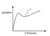
- the adhesive film 1 for metal terminals of the present disclosure is JIS.
- stress (MPa) and strain (mm) obtained by performing a tensile test under the conditions of a temperature of 25 ° C., a tensile speed of 175 mm / min, and a distance between chucks of 30 mm, which is a method conforming to the regulation of K7127, is shown.
- the descending yield stress obtained from the graph is preferably 17.0 MPa or more, more preferably 18.0 MPa or more, and preferably 28.0 MPa or less, more preferably 26.0 MPa or less. is there.
- Preferred ranges of the descending yield point stress include about 17.0 to 28.0 MPa, about 17.0 to 26.0 MPa, about 18.0 to 28.0 MPa, and about 18.0 to 26.0 MPa. Of these, about 18.0 to 26.0 MPa is particularly preferable.
- the range of the descending yield stress which is generally preferable in terms of adhesion, flexibility, and followability, is about 17.0 to 18.0 MPa.
- the method for measuring the descending yield stress is as follows.
- the descending yield stress of the adhesive film 1 for metal terminals of the present disclosure includes the laminated structure, the melting point of each layer, the MFR, the thickness, the thickness ratio, and the T-die, inflation, etc. in the production of the adhesive film 1 for metal terminals. It can be adjusted according to conditions (for example, extrusion width from T-die, stretching ratio, stretching speed, heat treatment temperature, etc.).
- the adhesive film 1 for metal terminals of the present disclosure has a thickness change rate close to 100% before and after heating and pressurizing for 12 seconds under the conditions of a temperature of 180 ° C. and a surface pressure of 0.0067 MPa (that is, heating and pressurizing). It is preferable that the change in thickness before and after is small or does not change), specifically, it is preferably 90 to 100%, more preferably 95 to 100%, and 96 to 100%. More preferred. When the rate of change in the thickness is within these ranges, the thickness of the adhesive film 1 for the metal terminal changes significantly when the adhesive film 1 for the metal terminal and the exterior material 10 for the power storage device are heat-sealed. The formation of voids between them is suppressed.
- the rate of change in the thickness is calculated by the formula of (thickness of adhesive film for metal terminals after heating and pressurization) / (thickness of adhesive film for metal terminals before heating and pressurizing) ⁇ 100.
- the shock absorption energy calculated from the area of the portion surrounded by the stress-strain curve obtained in the above ⁇ tensile elastic modulus A after heating and pressurization> is preferably about 90 MPa or more, more preferably about. It is 140 MPa or more, preferably about 400 MPa or less, more preferably about 300 MPa or less, and a preferable range is about 90 to 400 MPa.
- a material having a small impact absorption energy value is easily broken without being accompanied by a large deformation, and a material having a large impact absorption energy value is a material that is tenacious and does not easily break after being greatly deformed.
- the total thickness of the adhesive film 1 for metal terminals of the present disclosure is, for example, about 120 ⁇ m or more, preferably about 140 ⁇ m or more, and more preferably about 150 ⁇ m or more from the viewpoint of enhancing the followability to the shape of the metal terminal 2.
- the upper limit of the total thickness of the adhesive film 1 for metal terminals of the present disclosure is, for example, about 200 ⁇ m.
- Preferred ranges of the total thickness of the adhesive film 1 for metal terminals of the present disclosure include about 120 to 200 ⁇ m, about 140 to 200 ⁇ m, and about 150 to 200 ⁇ m.
- 145 is particularly preferable. It is about 155 ⁇ m.
- the adhesive film 1 for metal terminals of the present disclosure is composed of the first polyolefin layer 12a so that the adhesive film 1 for metal terminals has the above-mentioned physical properties. It is preferable that it is.
- the adhesive film 1 for metal terminals of the present disclosure includes at least a structure in which the base material 11 and the first polyolefin layer 12a are laminated, and will be described above. It is preferable that the laminate has the characteristics, and at least the first polyolefin layer 12a, the base material 11, and the second polyolefin layer 12b are laminated in this order, and the laminate has the above-mentioned characteristics. Is preferable.
- the base material 11 is a layer that functions as a support for the adhesive film 1 for metal terminals, and is provided as needed.
- the material forming the base material 11 is not particularly limited.
- the material forming the base material 11 include polyolefins, polyamides, polyesters, epoxy resins, acrylic resins, fluororesins, silicon resins, phenol resins, polyetherimides, polyimides, polycarbonates, mixtures and copolymers thereof, and the like.
- polyolefin is particularly preferable. That is, the material forming the base material 11 is preferably a resin containing a polyolefin skeleton such as polyolefin or acid-modified polyolefin.
- the fact that the resin constituting the base material 11 contains a polyolefin skeleton can be analyzed by, for example, infrared spectroscopy, gas chromatography-mass spectrometry, or the like.
- polystyrene resin examples include low-density polyethylene, medium-density polyethylene, high-density polyethylene, linear low-density polyethylene, and other polyethylene; homopolypropylene, polypropylene block copolymer (for example, propylene and ethylene block copolymer), and polypropylene. Crystalline or amorphous polypropylenes such as random copolymers (eg, random copolymers of propylene and ethylene); ethylene-butene-propylene tarpolymers; and the like. Among these polyolefins, polyethylene and polypropylene are preferable, and polypropylene is more preferable.
- polyamide examples include an aliphatic polyamide such as nylon 6, nylon 66, nylon 610, nylon 12, nylon 46, and a copolymer of nylon 6 and nylon 66; derived from terephthalic acid and / or isophthalic acid.
- Hexamethylenediamine-isophthalic acid-terephthalic acid copolymerized polyamide such as nylon 6I, nylon 6T, nylon 6IT, nylon 6I6T (I stands for isophthalic acid, T stands for terephthalic acid), polymethoxylylen adipamide, which contains the constituent units.
- Polyamide containing aromatics such as (MXD6); alicyclic polyamide such as polyaminomethylcyclohexylazipamide (PACM6); and a polyamide obtained by copolymerizing a lactam component and an isocyanate component such as 4,4'-diphenylmethane-diisocyanate.
- Polyamide copolymer and polyether ester amide copolymer which are copolymers of copolymerized polyamide and polyester or polyalkylene ether glycol; these copolymers and the like can be mentioned. These polyamides may be used alone or in combination of two or more.
- polyester a copolymerized polyester containing polyethylene terephthalate, polybutylene terephthalate, polyethylene naphthalate, polybutylene naphthalate, polyethylene isophthalate, and ethylene terephthalate as the main body of the repeating unit, and butylene terephthalate as the main body of the repeating unit.
- examples thereof include the copolymerized polyester.
- copolymerized polyester having ethylene terephthalate as the main body of the repeating unit specifically, a copolymer polyester having ethylene terephthalate as the main body of the repeating unit and polymerizing with ethylene isophthalate (hereinafter, polyethylene (terephthalate / isophthalate)).
- the copolymerized polyester having butylene terephthalate as the main body of the repeating unit specifically, a copolymer polyester which polymerizes with butylene isophthalate using butylene terephthalate as the main body of the repeating unit (hereinafter, polybutylene (terephthalate / isophthalate)).
- polybutylene (terephthalate / adipate) a copolymer polyester which polymerizes with butylene isophthalate using butylene terephthalate as the main body of the repeating unit
- polybutylene (terephthalate / isophthalate) a copolymer polyester which polymerizes with butylene isophthalate using butylene terephthalate as the main body of the repeating unit
- polybutylene (terephthalate / isophthalate) a copolymer polyester which polymerizes with butylene isophthalate using butylene terephthalate as the main body of the repeating
- the base material 11 may be formed of a non-woven fabric formed of the above resin.
- the base material 11 is preferably composed of the above-mentioned polyolefin, polyamide or the like.
- the base material 11 can be made into a layer containing the colorant. It is also possible to select a resin having low transparency and adjust the light transmittance.
- a resin having low transparency can be used, or a film having low transparency can be used.
- the base material 11 is a non-woven fabric, a non-woven fabric using fibers or binders containing a colorant or a non-woven fabric having low transparency can be used.
- the melt mass flow rate (MFR) of the base material 11 at 230 ° C. satisfies the above-mentioned characteristics and is applied to the metal terminals a plurality of times before being adhered to the metal terminals. From the viewpoint of exhibiting higher adhesion strength, it is preferably 8 g / 10 minutes or less, more preferably 4 g / 10 minutes or less, and for metal terminals having excellent flexibility (good evaluation of bending test described later).
- the adhesive film 1 is preferably 1 g / 10 minutes or more, more preferably 2 g / 10 minutes or more, and the preferable range is about 1 to 8 g / 10 minutes, about 1 to 4 g / 10 minutes, 2 About 8 g / 10 minutes and about 2 to 4 g / 10 minutes can be mentioned.
- the base material layer 11 is a polyolefin layer (a layer formed of polyolefin)
- the melt mass flow rate (MFR) of the base material 11 is a value (g / 10 minutes) at 230 ° C. measured in accordance with JIS K7210-1: 2014 (ISO 1133-1: 2011). ..
- the melting point of the base material 11 exhibits higher adhesion strength to the metal terminal when it is heated and pressurized a plurality of times before being adhered to the metal terminal while satisfying the above-mentioned characteristics.
- the adhesive film 1 for metal terminals which is preferably 130 ° C. or higher, more preferably 150 ° C. or higher, and has excellent flexibility (the evaluation of the bending test described later is good), is preferable.
- the melting point of the base material 11 is measured by the method described in Examples.
- the surface of the base material 11 may be subjected to known easy-adhesion means such as corona discharge treatment, ozone treatment, and plasma treatment, if necessary.
- the thickness of the base material 11 is preferably about 50 ⁇ m from the viewpoint of exhibiting higher adhesion strength to the metal terminals when heated and pressurized a plurality of times before being adhered to the metal terminals. As described above, it is more preferably about 60 ⁇ m or more, further preferably about 80 ⁇ m or more, further preferably about 90 ⁇ m or more, and preferably about 150 ⁇ m or less, more preferably about 130 ⁇ m or less, still more preferably about 120 ⁇ m or less.
- the range is about 50 to 150 ⁇ m, about 50 to 130 ⁇ m, about 50 to 120 ⁇ m, about 60 to 150 ⁇ m, about 60 to 130 ⁇ m, about 60 to 120 ⁇ m, about 80 to 150 ⁇ m, about 80 to 130 ⁇ m, about 80 to 120 ⁇ m, 90.
- Examples thereof include about 150 ⁇ m, about 90 to 130 ⁇ m, and about 90 to 120 ⁇ m. Among these, about 90 to 120 ⁇ m is particularly preferable.
- the adhesive film 1 for metal terminals of the present disclosure preferably includes a first polyolefin layer 12a.
- the adhesive film 1 for metal terminals of the present disclosure is composed of a single layer, it is preferable that the adhesive film 1 for metal terminals is composed of a first polyolefin layer 12a as shown in FIG.
- the adhesive film 1 for metal terminals of the present disclosure has a plurality of layers, it is preferable that the base material 11 and the first polyolefin layer 12a are laminated at least, and are shown in FIGS. 6 and 7.
- the first polyolefin layer 12a, the base material 11, and the second polyolefin layer 12b are laminated in this order. Further, in the adhesive film 1 for metal terminals of the present disclosure, it is preferable that the first polyolefin layer 12a and the second polyolefin layer 12b are located on the surfaces on both sides, respectively.
- At least one of the first polyolefin layer 12a and the second polyolefin layer 12b preferably contains an acid-modified polyolefin, and the first polyolefin layer 12a and the second polyolefin layer 12b contain an acid-modified polyolefin. Is even more preferable.
- one of the first and second polyolefin layers 12a and 12b is formed of acid-modified polyolefin
- one of the first and second polyolefin layers 12a and 12b is formed of acid-modified polyolefin.
- the other may be formed of polyolefin, or both the first and second polyolefin layers 12a and 12b may be formed of acid-modified polyolefin.
- Acid-modified polyolefins have a high affinity for thermosetting resins such as metals and polyolefins.
- polyolefin has a high affinity with thermosetting resins such as polyolefin. Therefore, in the adhesive film 1 for metal terminals of the present disclosure, by arranging the layer formed of the acid-modified polyolefin on the side of the metal terminal 2, the adhesive film 1 for metal terminals, the metal terminal 2, and the heat-sealing property Excellent adhesion can be exhibited at the interface with the resin layer 35.
- the layer formed of polyolefin on the heat-sealing resin layer 35 side of the exterior material 10 for the power storage device, at the interface between the adhesive film 1 for metal terminals and the heat-sealing resin layer 35, It is possible to exhibit even better adhesion.
- the adhesive film 1 for metal terminals is preferably a laminate in which a first polyolefin layer 12a, a base material 11, and a second polyolefin layer 12b are sequentially provided. As shown in FIGS. 6 and 7, for example, the adhesive film 1 for metal terminals has a laminated structure in which the first polyolefin layer 12a / the base material 11 / the second polyolefin layer 12b are laminated in this order.
- the adhesive film 1 for metal terminals has a three-layer structure in which an acid-modified polypropylene layer / polypropylene layer / acid-modified polypropylene layer is laminated in this order, or a polypropylene layer / polypropylene layer / acid-modified polypropylene layer in this order.
- a laminated three-layer structure is particularly preferable.
- the adhesive film 1 for metal terminals has a three-layer structure in which polypropylene layer / polypropylene layer / acid-modified polypropylene layer are laminated in this order, the acid-modified polypropylene layer constituting one surface is placed on the metal terminal 2 side.
- the adhesive film 1 for the metal terminal is made of the power storage device exterior material 10 and the metal. It can be brought into close contact with the terminal 2 particularly preferably.
- the acid-modified polyolefin is not particularly limited as long as it is an acid-modified polyolefin, but preferably an unsaturated carboxylic acid or a polyolefin graft-modified with an anhydride thereof. ..
- the acid-modified polyolefin examples include polyethylenes such as low-density polyethylene, medium-density polyethylene, high-density polyethylene, and linear low-density polyethylene; homopolypropylene and polypropylene block copolymers (for example, propylene and ethylene block copolymers). ), Polypropylene random copolymers (eg, propylene and ethylene random copolymers) and other crystalline or amorphous polypropylenes; ethylene-butene-propylene tarpolymers and the like.
- polyethylene and polypropylene are preferable.
- the acid-modified polyolefin may be a cyclic polyolefin.
- the carboxylic acid-modified cyclic polyolefin means that a part of the monomer constituting the cyclic polyolefin is copolymerized in place of ⁇ , ⁇ -unsaturated carboxylic acid or its anhydride, or ⁇ , with respect to the cyclic polyolefin. It is a polymer obtained by block-polymerizing or graft-polymerizing ⁇ -unsaturated carboxylic acid or its anhydride.
- the acid-modified cyclic polyolefin is a copolymer of an olefin and a cyclic monomer
- examples of the olefin that is a constituent monomer of the cyclic polyolefin include ethylene, propylene, 4-methyl-1-pentene, butadiene, and isoprene.
- Examples of the cyclic monomer which is a constituent monomer of the cyclic polyolefin include cyclic alkenes such as norbornene; specific examples thereof include cyclic diene such as cyclopentadiene, dicyclopentadiene, cyclohexadiene, and norbornadiene.
- cyclic alkene is preferable, and norbornene is more preferable.
- Styrene is also mentioned as a constituent monomer.
- Examples of the carboxylic acid or its anhydride used for acid modification include maleic acid, acrylic acid, itaconic acid, crotonic acid, maleic anhydride, itaconic anhydride and the like.
- a peak derived from maleic anhydride is detected.
- a peak derived from maleic acid is detected in the vicinity of the wave number of 1760 cm -1 and near the wave number 1780 cm -1.
- first and second polyolefin layers 12a and 12b are layers composed of maleic anhydride-modified polyolefin
- a peak derived from maleic anhydride is detected when measured by infrared spectroscopy.
- the peak may become small and may not be detected. In that case, it can be analyzed by nuclear magnetic resonance spectroscopy.
- the polyolefin is the same as that exemplified as the above-mentioned acid-modified polyolefin or acid-modified cyclic polyolefin. Can be exemplified.
- the first and second polyolefin layers 12a and 12b may be formed by one kind of resin component alone, or may be formed by a blend polymer in which two or more kinds of resin components are combined. Further, the first and second polyolefin layers 12a and 12b may be formed of only one layer, respectively, or may be formed of two or more layers with the same or different resin components.
- first and second polyolefin layers 12a and 12b may each contain a filler, if necessary. Since the first and second polyolefin layers 12a and 12b contain the filler, the filler functions as a spacer, so that the metal terminal 2 and the barrier layer 33 of the exterior material 3 for the power storage device are short-circuited. Can be effectively suppressed.
- the particle size of the filler may be in the range of about 0.1 to 35 ⁇ m, preferably about 5.0 to 30 ⁇ m, and more preferably about 10 to 25 ⁇ m.
- the content of the filler is about 5 to 30 parts by mass, more preferably about 10 to 20 parts by mass, respectively, with respect to 100 parts by mass of the resin components forming the first and second polyolefin layers 12a and 12b. Can be mentioned.
- the filler either an inorganic type or an organic type can be used.
- the inorganic filler include carbon (carbon, graphite), silica, aluminum oxide, barium titanate, iron oxide, silicon carbide, zirconium oxide, zirconium silicate, magnesium oxide, titanium oxide, calcium aluminate, and calcium hydroxide.
- the organic filler include fluororesin, phenol resin, urea resin, epoxy resin, acrylic resin, benzoguanamine / formaldehyde condensate, melamine / formaldehyde condensate, polymethylmethacrylate crosslinked product, polyethylene crosslinked product and the like. Can be mentioned.
- aluminum oxide, silica, fluororesin, acrylic resin, and benzoguanamine / formaldehyde condensate are preferable, and among these, spherical aluminum oxide and silica are more preferable.
- a method of mixing the filler with the resin components forming the first and second polyolefin layers 12a and 12b a method of melt-blending both of them with a Banbury mixer or the like in advance and making a masterbatch into a predetermined mixing ratio.
- a direct mixing method with a resin component or the like can be adopted.
- the first and second polyolefin layers 12a and 12b may each contain a pigment, if necessary.
- the pigment various inorganic pigments can be used.
- carbon (carbon, graphite) exemplified in the above-mentioned filler can be preferably exemplified.
- Carbon (carbon, graphite) is a material generally used inside a power storage device, and there is no risk of elution into an electrolytic solution.
- a sufficient coloring effect can be obtained with an addition amount having a large coloring effect and not hindering the adhesiveness, and the added resin can be increased in apparent melt viscosity without being melted by heat.
- the amount of the pigment added is, for example, when carbon black having a particle size of about 0.03 ⁇ m is used, the first and second polyolefin layers 12a and 12b are added. About 0.05 to 0.3 parts by mass, preferably about 0.1 to 0.2 parts by mass, respectively, with respect to 100 parts by mass of the resin component forming the above.
- the filler and the pigment When the filler and the pigment are added to the first and second polyolefin layers 12a and 12b, the filler and the pigment may be added to the same first and second polyolefin layers 12a and 12b, but the metal terminal From the viewpoint of not impairing the heat-sealing property of the adhesive film 1, the filler and the pigment are preferably added separately in the first and second polyolefin layers 12a and 12b.
- the first and second polyolefin layers 12a and 12b can be made of a polyolefin film or an acid-modified polyolefin film, respectively.
- the resin film formed of the above-mentioned polyolefin or acid-modified polyolefin is used as a base material 11 by using, for example, a dry laminating method.
- an adhesive film for metal terminals can be suitably manufactured.
- the adhesive film for metal terminals can be suitably produced by extruding the resins constituting the first and second polyolefin layers 12a and 12b onto the base material 11.
- the melt mass flow rate (MFR) of the first and second polyolefin layers 12a and 12b at 230 ° C. is preferably about 5 g / 10 minutes from the viewpoint of enhancing the followability to the shape of the metal terminal while satisfying the above-mentioned characteristics.
- the above is more preferably about 7 g / 10 minutes or more, further preferably about 8 g / 10 minutes or more, preferably about 11 g / 10 minutes or less, more preferably about 10 g / 10 minutes or less, and the preferred range is 5 to 11 g / 10 minutes, 5 to 10 g / 10 minutes, 7 to 11 g / 10 minutes, 7 to 10 g / 10 minutes, 8 to 11 g / 10 minutes, 8 to 10 g / 10 minutes.
- MFRs melt mass flow rates
- the MFR value of the acid-modified polyolefin layer satisfies the above value.
- the melting points of the first and second polyolefin layers 12a and 12b are preferably about 120 ° C. or higher, more preferably about 130 ° C., from the viewpoint of enhancing the followability to the shape of the metal terminal while satisfying the above-mentioned characteristics.
- the above is more preferably about 160 ° C. or lower, more preferably about 150 ° C. or lower, and the preferred ranges are about 120 to 160 ° C., about 120 to 150 ° C., about 130 to 160 ° C., and 130 to 150 ° C. Degree.
- the melting points of the first and second polyolefin layers 12a and 12b are measured by the method described in Examples.
- the surface of the first and second polyolefin layers 12a and 12b composed of the resin film is required. Therefore, known easy-adhesion means such as corona discharge treatment, ozone treatment, and plasma treatment may be applied.
- the corona discharge treatment enhances the adhesion between the base material 11 and the first polyolefin layer 12a and the second polyolefin layer 12b, and provides excellent sealing performance between the exterior material for the power storage device and the metal terminal. Can be granted.
- the thicknesses of the first and second polyolefin layers 12a and 12b are from the viewpoint of exhibiting higher adhesion strength to the metal terminals when they are heated and pressed a plurality of times before being adhered to the metal terminals. Therefore, it is preferably about 10 ⁇ m or more, more preferably about 15 ⁇ m or more, and preferably about 50 ⁇ m or less, more preferably about 45 ⁇ m or less, still more preferably 30 ⁇ m or less.
- the preferable ranges of the thicknesses of the first and second polyolefin layers 12a and 12b are about 10 to 50 ⁇ m, about 10 to 45 ⁇ m, about 10 to 30 ⁇ m, about 15 to 50 ⁇ m, about 15 to 45 ⁇ m, and about 10 to 30 ⁇ m, respectively. Of these, 10 to 30 ⁇ m is particularly preferable.
- the ratio of the thickness of the base material 11 to the total thickness of the first and second polyolefin layers 12a and 12b heating and pressurization are performed a plurality of times until they are adhered to the metal terminals while satisfying the above-mentioned characteristics.
- it is preferably about 0.7 or more, more preferably about 1.0 or more, and preferably about 4.0 or less, from the viewpoint of exhibiting higher adhesion strength to the metal terminal. It is preferably about 2.0 or less, and the preferred ranges are about 0.7 to 4.0, about 0.7 to 2.0, about 1.0 to 4.0, and about 1.0 to 2.0. Among these, about 1.0 to 4.0 is particularly preferable.
- the ratio of the thickness of the acid-modified polypropylene layer in the adhesive film 1 for metal terminals satisfies these values.
- the decrease in water vapor barrier property is suppressed. If the decrease in water vapor barrier property is suppressed, the life of the power storage device is expected to be extended and the long-term stability is expected. From this point of view, the ratio is preferably the upper limit.
- the total thickness of the adhesive film 1 for metal terminals is 100%, and the ratio of the total thickness of the first and second polyolefin layers 12a and 12b is preferably about 15 to 60%, more preferably 20 to 40%. Degree.
- the adhesion accelerator layer 13 is a layer provided as needed for the purpose of firmly adhering the base material 11 and the first and second polyolefin layers 12a and 12b (see FIG. 7).
- the adhesion accelerator layer 13 may be provided only on one side between the base material 11 and the first and second polyolefin layers 12a and 12b, or may be provided on both sides.
- the adhesion accelerator layer 13 can be formed by using a known adhesion accelerator such as isocyanate-based, polyethyleneimine-based, polyester-based, polyurethane-based, and polybutadiene-based. From the viewpoint of further improving the electrolytic solution resistance, among these, it is preferably formed by an isocyanate-based adhesion accelerator.
- a known adhesion accelerator such as isocyanate-based, polyethyleneimine-based, polyester-based, polyurethane-based, and polybutadiene-based. From the viewpoint of further improving the electrolytic solution resistance, among these, it is preferably formed by an isocyanate-based adhesion accelerator.
- an isocyanate-based adhesion accelerator one composed of an isocyanate component selected from a triisocyanate monomer and a polymeric MDI has excellent lamination strength and little decrease in lamination strength after immersion in an electrolytic solution.
- triphenylmethane-4,4', 4 "-triisocyanate which is a triisocyanate monomer and polymethylene polyphenyl polyisocyanate which is a polymeric MDI (NCO content is about 30%, viscosity is 200 to 700 mPa ⁇ s).
- NCO content is about 30%, viscosity is 200 to 700 mPa ⁇ s.
- the adhesion accelerator layer 13 can be formed by applying and drying by a known coating method such as a bar coating method, a roll coating method, or a gravure coating method.
- the amount of the adhesion accelerator applied is about 20 to 100 mg / m 2 in the case of the adhesion accelerator made of triisocyanate, preferably about 40 to 60 mg / m 2 and in the case of the adhesion accelerator made of polypeptide MDI. , 40 to 150 mg / m 2 , preferably about 60 to 100 mg / m 2 , and in the case of a two-component curing type adhesion accelerator containing polyethyleneimine as a main agent and polycarbodiimide as a cross-linking agent, 5 to 50 mg.
- the triisocyanate monomer is a monomer having three isocyanate groups in one molecule
- the polypeptide MDI is a mixture of MDI and an MDI oligomer obtained by polymerizing MDI, and is represented by the following formula.
- the adhesive film 1 for metal terminals of the present disclosure can be produced, for example, by laminating the first and second polyolefin layers 12a and 12b on both surfaces of the base material 11.
- the base material 11 and the first and second polyolefin layers 12a and 12b can be laminated by a known method such as an extrusion lamination method or a thermal lamination method.
- the adhesion promoter constituting the adhesion promoter layer 13 can be used in the above method.
- the first and second polyolefin layers 12a and 12b may be laminated on the adhesion accelerator layer 13 by coating and drying on the base material 11.
- the method of interposing the adhesive film 1 for the metal terminal between the metal terminal 2 and the exterior material 3 for the power storage device is not particularly limited.
- the metal terminal 2 is the power storage device.
- the adhesive film 1 for metal terminals may be wound around the metal terminals 2 at the portion sandwiched by the exterior material 3.
- both sides of the metal terminal 2 are formed so that the adhesive film 1 for the metal terminal crosses the two metal terminals 2 at the portion where the metal terminal 2 is sandwiched by the exterior material 3 for the power storage device. It may be placed on the side.
- the adhesive film 1 for metal terminals of the present disclosure is used by interposing it between the metal terminal 2 and the exterior material 3 for a power storage device.
- the metal terminal 2 (tab) is a conductive member electrically connected to an electrode (positive electrode or negative electrode) of the power storage device element 4, and is made of a metal material.
- the metal material constituting the metal terminal 2 is not particularly limited, and examples thereof include aluminum, nickel, and copper.
- the metal terminal 2 connected to the positive electrode of the lithium ion power storage device is usually made of aluminum or the like.
- the metal terminal 2 connected to the negative electrode of the lithium ion power storage device is usually made of copper, nickel or the like.
- the surface of the metal terminal 2 is preferably subjected to chemical conversion treatment from the viewpoint of enhancing the electrolyte resistance.
- specific examples of the chemical conversion treatment include known methods for forming a corrosion-resistant film such as a phosphate, a chromate, a fluoride, and a triazine thiol compound.
- a phosphoric acid chromate treatment using a method composed of three components of a phenol resin, a chromium (III) fluoride compound, and phosphoric acid is preferable.
- the size of the metal terminal 2 may be appropriately set according to the size of the power storage device used and the like.
- the thickness of the metal terminal 2 is preferably about 50 to 1000 ⁇ m, more preferably about 70 to 800 ⁇ m.
- the length of the metal terminal 2 is preferably about 1 to 200 mm, more preferably about 3 to 150 mm.
- the width of the metal terminal 2 is preferably about 1 to 200 mm, more preferably about 3 to 150 mm.
- Examples of the exterior material 3 for a power storage device include those having a laminated structure composed of at least a laminated body having a base material layer 31, a barrier layer 33, and a thermosetting resin layer 35 in this order.
- FIG. 8 shows, as an example of the cross-sectional structure of the exterior material 3 for a power storage device, a base material layer 31, an adhesive layer 32 provided as needed, a barrier layer 33, an adhesive layer 34 provided as needed, and thermosetting. The mode in which the adhesive resin layer 35 is laminated in this order is shown.
- the base material layer 31 is on the outer layer side
- the thermosetting resin layer 35 is the innermost layer.
- FIGS. 1 to 3 show the power storage device 10 when the embossed type exterior material 3 for the power storage device is used, the exterior material 3 for the power storage device is molded. It may be an embossed pouch type.
- the pouch type includes a three-way seal, a four-way seal, a pillow type, and the like, but any type may be used.
- the thickness of the laminate constituting the exterior material 3 for the power storage device is not particularly limited, but the upper limit is preferably about 180 ⁇ m or less, about 160 ⁇ m or less, and about 155 ⁇ m or less from the viewpoint of cost reduction, energy density improvement, and the like. , About 140 ⁇ m or less, about 130 ⁇ m or less, about 120 ⁇ m or less, and the lower limit is preferably about 35 ⁇ m or more, about 35 ⁇ m or more, from the viewpoint of maintaining the function of the exterior material 3 for the power storage device of protecting the power storage device element 4.
- 45 ⁇ m or more, about 60 ⁇ m or more, and about 80 ⁇ m or more are mentioned, and preferable ranges are, for example, about 35 to 180 ⁇ m, about 35 to 160 ⁇ m, about 35 to 155 ⁇ m, about 35 to 140 ⁇ m, about 35 to 130 ⁇ m, and about 35 to 120 ⁇ m.
- the base material layer 31 is a layer that functions as a base material for the power storage device exterior material, and is a layer that forms the outermost layer side.
- the material forming the base material layer 31 is not particularly limited as long as it has an insulating property.
- Examples of the material forming the base material layer 31 include polyester, polyamide, epoxy, acrylic, fluororesin, polyurethane, silicon resin, phenol, polyetherimide, polyimide, and a mixture or copolymer thereof.
- Polyesters such as polyethylene terephthalate and polybutylene terephthalate are excellent in electrolytic solution resistance and have an advantage that whitening or the like is unlikely to occur due to adhesion of the electrolytic solution, and are preferably used as a material for forming the base material layer 31.
- the polyamide film has excellent stretchability, can prevent whitening due to resin cracking of the base material layer 31 during molding, and is suitably used as a material for forming the base material layer 31.
- the base material layer 31 may be formed of a uniaxially or biaxially stretched resin film, or may be formed of an unstretched resin film. Among them, a uniaxially or biaxially stretched resin film, particularly a biaxially stretched resin film, is preferably used as a base material layer 31 because its heat resistance is improved by orientation crystallization.
- examples of the resin film forming the base material layer 31 include nylon and polyester, and more preferably biaxially stretched nylon and biaxially stretched polyester.
- the base material layer 31 can be laminated with resin films of different materials in order to improve pinhole resistance and insulation when used as a packaging for a power storage device.
- resin films of different materials include a multilayer structure in which a polyester film and a nylon film are laminated, and a multilayer structure in which a biaxially stretched polyester and a biaxially stretched nylon are laminated.
- the resin films may be bonded via an adhesive, or may be directly laminated without an adhesive.
- a method of bonding in a heat-melted state such as a coextrusion method, a sandrami method, and a thermal laminating method can be mentioned.
- the base material layer 31 may have low friction in order to improve moldability.
- the friction coefficient of the base material layer 31 is not particularly limited, and examples thereof include 1.0 or less.
- Examples of reducing the friction of the base material layer 31 include matting treatment, formation of a thin film layer of a slip agent, and a combination thereof.
- the thickness of the base material layer 31 is, for example, about 10 to 50 ⁇ m, preferably about 15 to 30 ⁇ m.
- the adhesive layer 32 is a layer arranged on the base material layer 31 as needed in order to impart adhesion to the base material layer 31. That is, the adhesive layer 32 is provided between the base material layer 31 and the barrier layer 33.
- the adhesive layer 32 is formed by an adhesive capable of adhering the base material layer 31 and the barrier layer 33.
- the adhesive used to form the adhesive layer 32 may be a two-component curable adhesive or a one-component curable adhesive.
- the adhesive mechanism used for forming the adhesive layer 32 is not particularly limited, and may be any of chemical reaction type, solvent volatilization type, heat melting type, thermal pressure type and the like.
- the resin component of the adhesive that can be used for forming the adhesive layer 32, it is excellent in spreadability, durability under high humidity conditions, yellowing suppressing action, heat deterioration suppressing action at the time of heat sealing, etc. From the viewpoint of suppressing a decrease in the lamination strength between the barrier layer 33 and effectively suppressing the occurrence of delamination, a polyurethane-based two-component curable adhesive is preferably used; a polyamide, polyester, or a modified polyolefin thereof. Blended resin can be mentioned.
- the adhesive layer 32 may be multi-layered with different adhesive components.
- the adhesive component arranged on the base layer 31 side is used as the base layer from the viewpoint of improving the lamination strength between the base layer 31 and the barrier layer 33. It is preferable to select a resin having excellent adhesiveness to 31 and select an adhesive component having excellent adhesiveness to the barrier layer 33 as the adhesive component arranged on the barrier layer 33 side.
- the adhesive component arranged on the barrier layer 33 side is preferably an acid-modified polyolefin, a metal-modified polyolefin, a polyester and an acid-modified polyolefin. Examples thereof include a mixed resin with and a resin containing a copolymerized polyester.
- the thickness of the adhesive layer 32 is, for example, about 2 to 50 ⁇ m, preferably about 3 to 25 ⁇ m.
- the barrier layer 33 is a layer having a function of improving the strength of the exterior material for the power storage device and preventing water vapor, oxygen, light, etc. from entering the inside of the power storage device.
- the barrier layer 33 is preferably a metal layer, that is, a layer made of metal. Specific examples of the metal constituting the barrier layer 33 include aluminum, stainless steel, titanium, and the like, preferably aluminum.
- the barrier layer 33 can be formed of, for example, a metal foil, a metal vapor deposition film, an inorganic oxide vapor deposition film, a carbon-containing inorganic oxide vapor deposition film, a film provided with these vapor deposition films, or the like, and is formed of a metal foil.
- the barrier layer is, for example, annealed aluminum (JIS H4160: 1994 A8021HO, JIS H4160). : 1994 A8079H-O, JIS H4000: 2014 A8021P-O, JIS H4000: 2014 A8079P-O) and the like are more preferably formed from soft aluminum foil.
- the thickness of the barrier layer 33 is preferably about 10 to 200 ⁇ m, more preferably about 20 to 100 ⁇ m, from the viewpoint of making the exterior material for the power storage device thinner and making it difficult for pinholes to occur even by molding. Be done.
- the barrier layer 33 is subjected to chemical conversion treatment in order to stabilize adhesion and prevent dissolution and corrosion.
- the chemical conversion treatment refers to a treatment for forming a corrosion-resistant film on the surface of the barrier layer.
- the adhesive layer 34 In the exterior material 3 for a power storage device, the adhesive layer 34 is provided as necessary between the barrier layer 33 and the thermosetting resin layer 35 in order to firmly bond the thermosetting resin layer 35. Is.
- the adhesive layer 34 is formed by an adhesive capable of adhering the barrier layer 33 and the thermosetting resin layer 35.
- the composition of the adhesive used to form the adhesive layer is not particularly limited, and examples thereof include a resin composition containing an acid-modified polyolefin.
- the acid-modified polyolefin the same ones as those exemplified in the first and second polyolefin layers 12a and 12b can be exemplified.
- the thickness of the adhesive layer 34 is, for example, about 1 to 40 ⁇ m, preferably about 2 to 30 ⁇ m.
- thermosetting resin layer 35 In the exterior material 3 for a power storage device, the thermosetting resin layer 35 corresponds to the innermost layer, and is a layer in which the heat-sealing resin layers are heat-sealed to each other when the power storage device is assembled to seal the power storage device element. ..
- the resin component used in the thermosetting resin layer 35 is not particularly limited as long as it can be heat-fused, and examples thereof include polyolefins and cyclic polyolefins.
- polystyrene resin examples include low-density polyethylene, medium-density polyethylene, high-density polyethylene, linear low-density polyethylene, and other polyethylene; homopolypropylene, polypropylene block copolymer (for example, propylene and ethylene block copolymer), and polypropylene. Random polypropylene (eg, random copolymer of propylene and ethylene) and other crystalline or amorphous polypropylene; ethylene-butene-propylene tarpolymer and the like. Among these polyolefins, polyethylene and polypropylene are preferable.
- the cyclic polyolefin is a copolymer of an olefin and a cyclic monomer
- examples of the olefin which is a constituent monomer of the cyclic polyolefin include ethylene, propylene, 4-methyl-1-pentene, butadiene, isoprene, and the like. Be done.
- examples of the cyclic monomer which is a constituent monomer of the cyclic polyolefin include cyclic alkenes such as norbornene; specific examples thereof include cyclic diene such as cyclopentadiene, dicyclopentadiene, cyclohexadiene, and norbornadiene.
- cyclic alkene is preferable, and norbornene is more preferable.
- Styrene is also mentioned as a constituent monomer.
- these resin components preferably crystalline or amorphous polyolefins, cyclic polyolefins, and blend polymers thereof; more preferably polyethylene, polypropylene, copolymers of ethylene and norbornene, and two or more of them. Blended polymers of.
- thermosetting resin layer 35 may be formed by one kind of resin component alone, or may be formed by a blend polymer in which two or more kinds of resin components are combined. Further, the thermosetting resin layer 35 may be formed of only one layer, or may be formed of two or more layers with the same or different resin components.
- the thickness of the thermosetting resin layer 35 is not particularly limited, but may be about 2 to 2000 ⁇ m, preferably about 5 to 1000 ⁇ m, and more preferably about 10 to 500 ⁇ m.
- the power storage device 10 of the present disclosure includes at least a power storage device element 4 having a positive electrode, a negative electrode, and an electrolyte, an exterior material 3 for a power storage device that seals the power storage device element 4, and an electric positive electrode and a negative electrode, respectively. It is provided with a metal terminal 2 which is connected to and protrudes to the outside of the exterior material 3 for a power storage device.
- the power storage device 10 of the present disclosure is characterized in that the adhesive film 1 for metal terminals of the present disclosure is interposed between the metal terminal 2 and the exterior material 3 for the power storage device. That is, the power storage device 10 of the present disclosure can be manufactured by a method including a step of interposing the adhesive film 1 for the metal terminal of the present disclosure between the metal terminal 2 and the exterior material 3 for the power storage device.
- the power storage device element 4 having at least a positive electrode, a negative electrode, and an electrolyte is provided with an exterior material 3 for the power storage device, with metal terminals 2 connected to each of the positive electrode and the negative electrode protruding outward.
- the adhesive film 1 for metal terminals of the present disclosure is interposed between the metal terminals 2 and the thermosetting resin layer 35, and the flange portion (thermosetting resin) of the exterior material for the power storage device is placed on the peripheral edge of the power storage device element 4. It is a region where the layers 35 are in contact with each other, and is covered so that the peripheral edge portion 3a) of the exterior material for the power storage device can be formed, and the thermosetting resin layers 35 of the flange portion are heat-sealed and sealed.
- thermosetting resin layer 35 of the power storage device exterior material 3 is set to be inside (the surface in contact with the power storage device element 4). Used.
- the exterior material for a power storage device of the present disclosure can be suitably used for a power storage device such as a battery (including a capacitor, a capacitor, etc.). Further, the exterior material for the power storage device of the present disclosure may be used for either a primary battery or a secondary battery, but is preferably a secondary battery.
- the type of the secondary battery to which the exterior material for the power storage device of the present disclosure is applied is not particularly limited, and for example, a lithium ion battery, a lithium ion polymer battery, an all-solid-state battery, a lead storage battery, a nickel / hydrogen storage battery, and a nickel / hydrogen storage battery.
- lithium ion batteries and lithium ion polymer batteries can be mentioned as suitable application targets of the exterior materials for power storage devices of the present disclosure.
- Example 1-16 and Comparative Example 1-6 Manufacturing of adhesive film for metal terminals>
- PP layer maleic anhydride-modified polypropylene having the melting point and melt mass flow rate (MFR) shown in Table 1 (hereinafter, may be referred to as “PPa”) is used as a first polyolefin layer (PPa layer) and a second polyolefin layer. (PPa layer).
- Example 1 to 12 and Comparative Example 3 the PPa layer / PP layer / PPa layer were laminated in order by extruding polypropylene and maleic anhydride-modified polypropylene in two types and three layers using a T-die extruder. An adhesive film for metal terminals was obtained. Further, in Examples 13 to 16 and Comparative Examples 4 to 6, an adhesive film for metal terminals in which a PPa layer / PP layer / PPa layer was laminated in this order was obtained by an inflation method.
- Physical properties such as tensile elastic modulus, yield stress, water vapor barrier property, and thickness change rate of the adhesive film for metal terminals shown in Table 2 include the melting point, MFR, thickness, and thickness ratio of the PPa layer and the PP layer.
- the melting points of the PP layer and the PPa layer shown in Table 1 are values measured by the following methods, respectively.
- the melting peak temperature was measured twice with a differential scanning calorimeter (DSC, differential scanning calorimeter Q200 manufactured by TA Instruments). Specifically, according to the procedure of JIS K7121: 2012 (Plastic transition temperature measurement method (Appendix 1 of JIS K7121: 1987)), the PP layer or PPa layer was subjected to -20 ° C by differential scanning calorimetry (DSC).
- melt mass flow rates (MFRs) of the PP layer and the PPa layer shown in Table 1 are values at 230 ° C. measured in accordance with JIS K7210-1: 2014 (ISO 1133-1: 2011), respectively. g / 10 minutes).
- ⁇ Tension elastic modulus B before heating and pressurizing> In accordance with JIS K7161-1 (ISO527-1), the adhesive film for metal terminals in a 25 ° C environment (metal terminals before heating and pressurizing in ⁇ tensile elastic modulus A after heating and pressurizing> described later). The tensile elastic modulus B of the adhesive film) was measured. Specifically, the adhesive films for metal terminals obtained in Examples and Comparative Examples were cut into strips having a width (TD) of 15 mm and a length (MD) of 50 mm.
- the adhesive film for metal terminals was subjected to the conditions of a tensile speed of 300 mm / min and a chuck distance of 30 mm using a Tencilon universal material tester (RTG-1210 manufactured by A & D Co., Ltd.) in an environment of 25 ° C. Then, the stress-strain curve of the test piece was obtained, and the tensile elastic modulus B of the adhesive film for metal terminals before heating and pressurization was calculated from the slope of the straight line connecting the two points of strain 0.05% and 0.25%. I asked. The results are shown in Table 2.
- ⁇ Tension elastic modulus A after heating and pressurizing> The tensile elastic modulus after heating and pressurizing was measured by the following procedure for 12 seconds under the conditions of a temperature of 180 ° C. and a surface pressure of 0.0067 MPa.
- the adhesive films for metal terminals obtained in Examples and Comparative Examples were cut into strips having a width (TD) of 15 mm and a length (MD) of 50 mm.
- the adhesive film for metal terminals is sandwiched between two tetrafluoroethylene-ethylene copolymer films (ETFE film, thickness 100 ⁇ m), and the film is placed on a hot plate heated to 180 ° C.
- ETFE film tetrafluoroethylene-ethylene copolymer films
- an exterior material for a power storage device (hereinafter, may be simply referred to as "exterior material”) was produced by the following procedure.
- An aluminum alloy foil (thickness 35 ⁇ m) was laminated on a base material layer (thickness 25 ⁇ m) made of a nylon film by a dry laminating method.
- a two-component urethane adhesive (polyol compound and aromatic isocyanate compound) is applied to one surface of a barrier layer made of an aluminum alloy foil, and an adhesive layer (thickness 3 ⁇ m) is applied on the aluminum alloy foil.
- a two-component urethane adhesive polyol compound and aromatic isocyanate compound
- an aging treatment was carried out to prepare a laminated body of the base material layer / adhesive layer / barrier layer.
- an adhesive layer made of maleic anhydride-modified polypropylene resin (thickness 20 ⁇ m, arranged on the metal layer side) and a thermosetting resin layer made of random polypropylene resin (thickness 15 ⁇ m).
- the innermost layer was extruded together to laminate an adhesive layer / thermosetting resin layer on the barrier layer.
- a base material layer, an adhesive layer, a barrier layer, an adhesive layer, and a thermosetting resin layer are laminated in this order as an exterior material for a power storage device.
- the obtained exterior material 3 was cut into squares having a length (MD) of 120 mm and a width (TD) of 120 mm (FIG. 11a).
- the adhesive film 1 for each metal terminal (hereinafter, may be simply referred to as "adhesive film") obtained in Examples and Comparative Examples is formed into a rectangle having a length (MD) of 120 mm and a width (TD) of 10 mm. I cut it.
- the exterior material 10 is bent in half in the vertical direction so that the thermosetting resin layer is on the inside, and two adhesive films for metal terminals are arranged between them so that the vertical and horizontal directions match.
- FIG. 11b A laminate in which the exterior material / adhesive film / adhesive film / exterior material was laminated in this order was obtained (FIG. 11b).
- the adhesive film is arranged between the exterior materials 10 along the long side to be heat-sealed, which will be described later.
- a heat seal bar stainless steel plate
- each layer of the laminate is heat-sealed at the positions of the long side and the short side of the laminate, and one short side is not heat-sealed. And said.
- the conditions for heat fusion were set to a temperature of 190 ° C., a surface pressure of 1.0 MPa, and once for 3 seconds using a heat seal bar having a width of 10 mm for the long side (s1 in FIG. 11c).
- a heat seal bar with a width of 7 m, heat seal once under the conditions of a temperature of 190 ° C., a surface pressure of 2.0 MPa, and 3 seconds, and then further, at a position 3 mm inside from the short side, the width.
- heat seal was performed once under the conditions of a temperature of 190 ° C. and a surface pressure of 2.0 MPa for 3 seconds. That is, the short side 2 was heat-sealed twice so as to have a width of 10 mm by shifting the position by 3 mm (s2 in FIG. 11c).
- the heat-sealed portion was cut off along the long-side direction so that the width of the heat-sealed portion on the long side was 3 mm, and the heat-sealed portion was dried in a dry room for one day (FIG. 11d).
- the short side that was not heat-sealed was also heat-sealed in the same manner as the short side to form a sealed bag (FIG. 11f).
- This sealed bag was allowed to stand in an environment of a temperature of 60 ° C. and a relative humidity of 90% for 30 days, and then the moisture content of the liquid taken out from the sealed bag was measured by the Karl Fischer method in a dry room. The results are shown in Table 2.
- ⁇ Rate of change in thickness> In the above ⁇ tensile elastic modulus A after heating and pressurizing>, the adhesive films for each metal terminal before and after heating and pressurizing for 12 seconds under the conditions of a temperature of 180 ° C. and a surface pressure of 0.0067 MPa (metal after heating and pressurizing).
- the rate of change in thickness was calculated from the formula of (thickness of adhesive film for terminals) / (thickness of adhesive film for metal terminals before heating and pressurization) ⁇ 100.
- the rate of change in thickness is an average value measured at three points in the MD direction of the adhesive film for metal terminals. The results are shown in Table 2.
- metal terminals aluminum (JIS H4160: 1994 A8079H-O) having a length of 50 mm, a width of 22.5 mm, and a thickness of 0.2 mm was prepared. Further, the adhesive films for metal terminals obtained in Examples and Comparative Examples were cut into a length of 45 mm and a width of 15 mm. Next, an adhesive film for metal terminals was placed on the metal terminals to obtain a laminate of metal terminals / adhesive films.
- the vertical direction and the horizontal direction of the metal terminal coincide with the length direction and the width direction of the adhesive film for the metal terminal, respectively, and the centers of the metal terminal and the adhesive film for the metal terminal coincide with each other.
- a tetrafluoroethylene-ethylene copolymer film (ETFE film, thickness 100 ⁇ m) was placed on the adhesive film for metal terminals of the laminate (the surface of the adhesive film for metal terminals was covered with the ETFE film).
- ETFE film tetrafluoroethylene-ethylene copolymer film
- the process of allowing to stand for 12 seconds in a heating and pressurizing environment at a temperature of 180 ° C. and a surface pressure of 0.016 MPa is a process assuming the heat and pressure applied in the temporary bonding step and the main bonding step.
- the results are shown in Table 2.
- ⁇ Followability evaluation 1 (adhesive film / metal terminal)>
- a metal terminal an aluminum foil (JIS H4160: 1994 A8079HO) having a thickness of 200 ⁇ m was prepared.
- the adhesive films for each metal terminal obtained in Examples and Comparative Examples were prepared.
- a metal terminal was sandwiched between the two adhesive films to obtain a laminate of the adhesive film / metal terminal / adhesive film.
- two tetrafluoroethylene-ethylene copolymer films (ETFE film, thickness 100 ⁇ m) are placed on a hot plate heated to 180 ° C. with the laminate sandwiched between them, and a sponge is used.
- a 500 g weight of the film was placed on the film and allowed to stand for 12 seconds to heat-fuse the adhesive film to the metal terminals (surface pressure 0.0067 MPa, contact area 300 mm 2 ).
- the metal terminals are sandwiched by the adhesive film, so that the periphery of the metal terminals is covered with the adhesive film, and the two adhesive films are heat-sealed to each other. Formed the part that is.
- the laminate after heat fusion is naturally cooled to 25 ° C., the cross section in the thickness direction is observed with a laser microscope, and the followability of the adhesive film for metal terminals to the shape of the metal terminals is evaluated according to the following criteria. It was. The results are shown in Table 2.
- A There are no bubbles between the adhesive film for metal terminals and the metal terminals B: There are no bubbles at the interface between the adhesive film for metal terminals and the metal terminals, but in the vicinity of the interface, the adhesive film for metal terminals There are air bubbles C: There are air bubbles at the interface between the adhesive film for metal terminals and the metal terminals, and there are air bubbles in the adhesive film for metal terminals even near the interface.
- ⁇ Followability evaluation 2 (adhesive film / exterior material)>
- a laminate of an adhesive film / metal terminal / adhesive film was produced in the same manner as in the procedure described in the followability evaluation 1 described above.
- the obtained laminate is sandwiched between the two exterior materials, and in this state, the exterior is sealed by using a heat seal tester at 180 ° C. and a surface pressure of 1.0 MPa for 3 seconds.
- a laminate was obtained by heat-sealing between the material and the adhesive film.
- the obtained laminate is naturally cooled to 25 ° C., and the cross section in the thickness direction is observed with a laser microscope to evaluate the followability of the adhesive film for metal terminals to the shape of the exterior material for the power storage device according to the following criteria. went.
- the shock absorption energy was calculated from the area of the portion surrounded by the stress-strain curve obtained by the ⁇ tensile elastic modulus A after heating and pressurization>. The results are shown in Table 2.
- the adhesive film for metal terminals of Examples 1 to 16 is interposed between the metal terminal electrically connected to the electrode of the power storage device element and the exterior material for the power storage device that seals the power storage device element.
- the adhesive films for metal terminals of Examples 1 to 16 having the above configuration are heated and pressurized a plurality of times before being adhered to the metal terminals. Demonstrates high adhesion strength to metal terminals.
- the adhesive films for metal terminals of Examples 1 and 2 have a sufficient adhesive strength of 45 N / 15 mm or more, and further, flexibility (bending test), thickness change rate, and impact. It was an adhesive film for metal terminals that was excellent in absorption energy, had good adhesion, flexibility, rate of change in thickness, and shock absorption energy, and had an excellent balance of overall characteristics. That is, in the adhesive film for metal terminals of the present disclosure, the tensile elastic modulus A is about 500 to 550 MPa, the tensile elastic modulus B is 420 to 480 MPa, and the difference between the tensile elastic moduli A and B is 40 to 75 MPa.
- the total thickness of the adhesive film for metal terminals is 145 to 155 ⁇ m, the thickness of the base material is 90 to 120 ⁇ m, and the thickness of the first polyolefin layer and the second polyolefin layer is 10 to 30 ⁇ m, respectively. Since the ratio of the thickness of the base material to the total thickness of the second polyolefin layer is 1.0 to 4.0, the adhesiveness, flexibility, rate of change in thickness, and shock absorption energy are good, and the overall thickness is comprehensive. An adhesive film for metal terminals with an excellent balance of characteristics.
- Example 17 Manufacturing of adhesive film for metal terminals>
- polypropylene (PP) having the melting point and melt mass flow rate (MFR) shown in Table 3 is used as the first polyolefin layer (PP layer), and maleic anhydride-modified polypropylene (PPa) is used as the second polyolefin layer (PPa).
- PP polypropylene
- MFR melt mass flow rate
- PPa maleic anhydride-modified polypropylene
- PPa second polyolefin layer
- Polypropylene (PP) and maleic anhydride-modified polypropylene (PPa) are extruded on both sides of a base material made of unstretched polypropylene film (CPP layer) with a T-die extruder, and the PP layer / CPP layer / PPa layer are sequentially extruded. A laminated adhesive film for metal terminals was obtained. The thickness of each layer of the PP layer / CPP layer / PPa layer is as shown in Table 4.
- the physical properties such as tensile elastic modulus, yield point stress, water vapor barrier property, and thickness change rate of the adhesive film for metal terminals shown in Table 4 are the same as in Examples 1 to 16, and the PP layer, PPa layer, and CPP layer are the same. Adjusted according to the melting point, MFR, thickness, thickness ratio, and T-die conditions (for example, extrusion width from T-die, draw ratio, draw rate, heat treatment temperature, etc.) in the production of the adhesive film 1 for metal terminals. did.
- the metal terminals electrically connected to the electrodes of the power storage device element and the exterior material for the power storage device that seals the power storage device element. It is an adhesive film for metal terminals interposed between and, and has a tensile elastic modulus A of 490 MPa or more. As is clear from the results shown in Table 4, the adhesive film for metal terminals of Example 17 having this configuration is made of metal when it is heated and pressed a plurality of times before being adhered to the metal terminals. Demonstrates high adhesion to terminals.
- Item 1 An adhesive film for metal terminals that is interposed between a metal terminal electrically connected to an electrode of a power storage device element and an exterior material for a power storage device that seals the power storage device element.
- the adhesive film for metal terminals is allowed to stand for 12 seconds in a heating and pressurizing environment having a temperature of 180 ° C. and a surface pressure of 0.0067 MPa, and further standing for 1 hour in an environment having a temperature of 25 ° C., and then having a temperature of 25 ° C.
- Item 2. Item 2.
- Adhesion for metal terminals according to Item 1 wherein the adhesive film for metal terminals has a tensile elastic modulus B of 700 MPa or less measured in an environment of a temperature of 25 ° C. before being exposed to the heating and pressurizing environment. Sex film.
- Item 3. Item 2. The adhesive film for metal terminals according to Item 2, wherein the difference in tensile elastic modulus is 5 MPa or more, which is calculated by subtracting the value of the tensile elastic modulus B from the value of the tensile elastic modulus A.
- Item 4. Item 2. The adhesive film for metal terminals according to any one of Items 1 to 3, wherein the adhesive film for metal terminals has a tensile elastic modulus A of 680 MPa or less.
- the adhesive film for metal terminals is a stress (MPa) obtained by performing a tensile test under the conditions of a temperature of 25 ° C., a tensile speed of 175 mm / min, and a distance between chucks of 30 mm by a method in accordance with JIS K7127.
- Item 2 The adhesive film for a metal terminal according to any one of Items 1 to 4, wherein the descending yield stress obtained from the graph showing the relationship between the strain (mm) and the strain (mm) is 17.0 MPa or more.
- Adhesive film for metal terminals according to the section. Rate of change in thickness (thickness of adhesive film for metal terminals after heating and pressurization / thickness of adhesive film for metal terminals before heating and pressurizing) x 100 Item 7.
- Item 9 The adhesive film for metal terminals according to Item 8, wherein the ratio of the thickness of the base material to the total thickness of the first polyolefin layer and the second polyolefin layer is 0.7 or more and 4.0 or less.
- Item 10. The adhesive film for metal terminals according to Item 8 or 9, wherein the thickness of the base material is 50 ⁇ m or more and 150 ⁇ m or less.
- Item 11. Item 2. The adhesive film for metal terminals according to any one of Items 8 to 10, wherein the thickness of the first polyolefin layer and the second polyolefin layer are 10 ⁇ m or more and 50 ⁇ m or less, respectively.
- Item 2 to any one of Items 8 to 11, wherein the melt mass flow rate at at least one of the first polyolefin layer and the second polyolefin layer at 230 ° C. is 7.2 g / 10 minutes or more and 9.8 g / 10 minutes or less.
- the described adhesive film for metal terminals Item 13.
- Item 2. The adhesive film for metal terminals according to any one of Items 8 to 12, wherein the melt mass flow rate of the base material at 230 ° C. is 1.8 g / 10 minutes or more and 5.0 g / 10 minutes or less.
- Item 14. Item 2.
- the exterior material for a power storage device is composed of a laminate having at least a base material layer, a barrier layer, and a thermosetting resin layer in this order.
- Item 2. The adhesive film for metal terminals according to any one of Items 1 to 15, wherein the adhesive film for metal terminals is interposed between the thermosetting resin layer and the metal terminals.
- Item 17. A metal terminal with an adhesive film for a metal terminal, wherein the adhesive film for the metal terminal according to any one of Items 1 to 16 is attached to the metal terminal.
- the power storage device element provided with at least a positive electrode, a negative electrode, and an electrolyte, an exterior material for the power storage device that seals the power storage device element, and the positive electrode and the negative electrode are electrically connected to each other.
- Item 19 The power storage device element provided with at least a positive electrode, a negative electrode, and an electrolyte, an exterior material for the power storage device that seals the power storage device element, and the positive electrode and the negative electrode are electrically connected to each other.
- the metal terminal adhesive film according to any one of Items 1 to 16 is interposed between the metal terminal and the exterior material for the power storage device, and the power storage device element is sealed with the exterior material for the power storage device.
- a method of manufacturing a power storage device which comprises a step of performing.
- Adhesive film for metal terminals Metal terminals 3 Exterior material for power storage device 3a Peripheral part of exterior material for power storage device 4 Power storage device element 10 Power storage device 11 Base material 12a First polyolefin layer 12b Second polyolefin layer 13 Adhesive accelerator layer 31 Base material layer 32 Adhesive layer 33 Barrier layer 34 Adhesive layer 35 Heat-sealing resin layer
Landscapes
- Engineering & Computer Science (AREA)
- Power Engineering (AREA)
- Chemical & Material Sciences (AREA)
- Chemical Kinetics & Catalysis (AREA)
- Electrochemistry (AREA)
- General Chemical & Material Sciences (AREA)
- Microelectronics & Electronic Packaging (AREA)
- Organic Chemistry (AREA)
- Physics & Mathematics (AREA)
- Thermal Sciences (AREA)
- Electric Double-Layer Capacitors Or The Like (AREA)
- Adhesives Or Adhesive Processes (AREA)
- Sealing Battery Cases Or Jackets (AREA)
- Secondary Cells (AREA)
- Connection Of Batteries Or Terminals (AREA)
- Laminated Bodies (AREA)
Priority Applications (5)
| Application Number | Priority Date | Filing Date | Title |
|---|---|---|---|
| CN202080050216.2A CN114096628A (zh) | 2019-07-10 | 2020-07-10 | 金属端子用粘接性膜、带有金属端子用粘接性膜的金属端子、使用了该金属端子用粘接性膜的蓄电器件和蓄电器件的制造方法 |
| JP2020564276A JP6885521B1 (ja) | 2019-07-10 | 2020-07-10 | 金属端子用接着性フィルム、金属端子用接着性フィルム付き金属端子、当該金属端子用接着性フィルムを用いた蓄電デバイス、及び蓄電デバイスの製造方法 |
| KR1020217039619A KR102920669B1 (ko) | 2019-07-10 | 2020-07-10 | 금속단자용 접착성 필름, 금속단자용 접착성 필름 부착 금속단자, 상기 금속단자용 접착성 필름을 사용한 축전 디바이스, 및 축전 디바이스의 제조 방법 |
| EP20837256.5A EP3998649A4 (en) | 2019-07-10 | 2020-07-10 | METAL TERMINAL ADHESIVE FOIL, METAL TERMINAL WITH METAL TERMINAL ADHESIVE FOIL, ENERGY STORAGE DEVICE WITH THIS METAL TERMINAL ADHESIVE FOIL AND METHOD OF MAKING AN ENERGY STORAGE DEVICE |
| US17/624,708 US20220290011A1 (en) | 2019-07-10 | 2020-07-10 | Adhesive film for metal terminal, metal terminal with adhesive film for metal terminal, power storage device using said adhesive film for metal terminal, and method for producing power storage device |
Applications Claiming Priority (4)
| Application Number | Priority Date | Filing Date | Title |
|---|---|---|---|
| JP2019-128632 | 2019-07-10 | ||
| JP2019128632 | 2019-07-10 | ||
| JP2019-184084 | 2019-10-04 | ||
| JP2019184084 | 2019-10-04 |
Publications (1)
| Publication Number | Publication Date |
|---|---|
| WO2021006350A1 true WO2021006350A1 (ja) | 2021-01-14 |
Family
ID=74114551
Family Applications (1)
| Application Number | Title | Priority Date | Filing Date |
|---|---|---|---|
| PCT/JP2020/027120 Ceased WO2021006350A1 (ja) | 2019-07-10 | 2020-07-10 | 金属端子用接着性フィルム、金属端子用接着性フィルム付き金属端子、当該金属端子用接着性フィルムを用いた蓄電デバイス、及び蓄電デバイスの製造方法 |
Country Status (6)
| Country | Link |
|---|---|
| US (1) | US20220290011A1 (https=) |
| EP (1) | EP3998649A4 (https=) |
| JP (3) | JP6885521B1 (https=) |
| KR (1) | KR102920669B1 (https=) |
| CN (1) | CN114096628A (https=) |
| WO (1) | WO2021006350A1 (https=) |
Cited By (6)
| Publication number | Priority date | Publication date | Assignee | Title |
|---|---|---|---|---|
| KR102447851B1 (ko) * | 2021-06-24 | 2022-09-27 | 나노캡 주식회사 | 겔전해질을 이용한 고전압의 초박형 전기이중층 커패시터 및 그 제조방법 |
| JP2022165772A (ja) * | 2021-04-20 | 2022-11-01 | 凸版印刷株式会社 | 端子用樹脂フィルム、及びそれを用いた蓄電デバイス |
| JP2022190244A (ja) * | 2021-06-14 | 2022-12-26 | 凸版印刷株式会社 | 蓄電装置用外装材及び蓄電装置 |
| JP7245570B1 (ja) | 2022-08-23 | 2023-03-24 | ビージェイテクノロジーズ株式会社 | タブリード封止用フィルム |
| JPWO2024080338A1 (https=) * | 2022-10-12 | 2024-04-18 | ||
| WO2025084379A1 (ja) * | 2023-10-17 | 2025-04-24 | 大日本印刷株式会社 | 金属端子用接着性フィルム及びその製造方法、金属端子用接着性フィルム付き金属端子、蓄電デバイス用外装材、蓄電デバイス用外装材と金属端子用接着性フィルムを備えるキット、並びに、蓄電デバイス及びその製造方法 |
Families Citing this family (2)
| Publication number | Priority date | Publication date | Assignee | Title |
|---|---|---|---|---|
| KR102878064B1 (ko) * | 2022-07-29 | 2025-10-28 | 후난 아이화 그룹 컴퍼니., 리미티드. | 코어 팩, 알루미늄 전해 콘덴서 및 그 패키지 방법 |
| WO2024216463A1 (zh) * | 2023-04-17 | 2024-10-24 | 宁德时代新能源科技股份有限公司 | 隔离膜、电池单体、电池和用电装置 |
Citations (4)
| Publication number | Priority date | Publication date | Assignee | Title |
|---|---|---|---|---|
| JP2014132538A (ja) * | 2013-01-07 | 2014-07-17 | Toppan Printing Co Ltd | 二次電池用金属端子被覆樹脂フィルムおよびその製造方法ならびに電池パック |
| JP2015079638A (ja) | 2013-10-17 | 2015-04-23 | 大倉工業株式会社 | 接着用テープ付き端子、接着用テープ付き端子の製造方法及び薄型電池 |
| JP2017069151A (ja) * | 2015-10-02 | 2017-04-06 | 大日本印刷株式会社 | 金属端子用接着性フィルム |
| WO2018110702A1 (ja) * | 2016-12-16 | 2018-06-21 | 大日本印刷株式会社 | 金属端子用接着性フィルム及び電池 |
Family Cites Families (13)
| Publication number | Priority date | Publication date | Assignee | Title |
|---|---|---|---|---|
| JP2008032691A (ja) * | 2006-06-29 | 2008-02-14 | Fuji Electric Systems Co Ltd | 水質監視システムおよび水質監視方法 |
| JP5720132B2 (ja) * | 2010-07-13 | 2015-05-20 | 凸版印刷株式会社 | 二次電池用金属端子被覆樹脂フィルム |
| CN103026528A (zh) * | 2010-08-11 | 2013-04-03 | 大仓工业株式会社 | 端子粘合用胶带的制造方法及端子粘合用胶带 |
| JP5659241B2 (ja) * | 2010-11-11 | 2015-01-28 | 藤森工業株式会社 | 封止フィルムの製造方法および封止フィルム |
| JP5849433B2 (ja) * | 2011-05-11 | 2016-01-27 | 凸版印刷株式会社 | 二次電池用電極端子 |
| JP5991335B2 (ja) * | 2013-03-07 | 2016-09-14 | 住友ベークライト株式会社 | 接着フィルム、ダイシングシート一体型接着フィルム、バックグラインドテープ一体型接着フィルム、バックグラインドテープ兼ダイシングシート一体型接着フィルム、積層体、積層体の硬化物、および半導体装置、並び半導体装置の製造方法 |
| JP6188009B2 (ja) * | 2013-03-11 | 2017-08-30 | 藤森工業株式会社 | 電池外装用積層体 |
| KR20160030937A (ko) * | 2013-07-17 | 2016-03-21 | 도판 인사츠 가부시키가이샤 | 이차 전지용 단자 피복 수지 필름, 이차 전지용 탭 부재, 및 이차 전지 |
| JP6648400B2 (ja) * | 2014-11-10 | 2020-02-14 | 凸版印刷株式会社 | 端子用樹脂フィルム、それを用いたタブ及び蓄電デバイス |
| JP6699105B2 (ja) * | 2015-08-04 | 2020-05-27 | 凸版印刷株式会社 | 端子用樹脂フィルム、それを用いたタブ及び蓄電デバイス |
| JP6143147B1 (ja) * | 2015-08-28 | 2017-06-07 | Dic株式会社 | ラミネート用接着剤、多層フィルム、及びこれを用いた二次電池 |
| JP2017139121A (ja) * | 2016-02-03 | 2017-08-10 | 大日本印刷株式会社 | 金属端子用接着性フィルム |
| KR102632999B1 (ko) * | 2017-04-05 | 2024-02-05 | 다이니폰 인사츠 가부시키가이샤 | 접착성 보호 필름, 전지 및 그 제조 방법 |
-
2020
- 2020-07-10 CN CN202080050216.2A patent/CN114096628A/zh active Pending
- 2020-07-10 EP EP20837256.5A patent/EP3998649A4/en active Pending
- 2020-07-10 WO PCT/JP2020/027120 patent/WO2021006350A1/ja not_active Ceased
- 2020-07-10 JP JP2020564276A patent/JP6885521B1/ja active Active
- 2020-07-10 KR KR1020217039619A patent/KR102920669B1/ko active Active
- 2020-07-10 US US17/624,708 patent/US20220290011A1/en active Pending
-
2021
- 2021-05-13 JP JP2021081848A patent/JP7822705B2/ja active Active
-
2025
- 2025-05-01 JP JP2025076269A patent/JP2025105929A/ja not_active Withdrawn
Patent Citations (4)
| Publication number | Priority date | Publication date | Assignee | Title |
|---|---|---|---|---|
| JP2014132538A (ja) * | 2013-01-07 | 2014-07-17 | Toppan Printing Co Ltd | 二次電池用金属端子被覆樹脂フィルムおよびその製造方法ならびに電池パック |
| JP2015079638A (ja) | 2013-10-17 | 2015-04-23 | 大倉工業株式会社 | 接着用テープ付き端子、接着用テープ付き端子の製造方法及び薄型電池 |
| JP2017069151A (ja) * | 2015-10-02 | 2017-04-06 | 大日本印刷株式会社 | 金属端子用接着性フィルム |
| WO2018110702A1 (ja) * | 2016-12-16 | 2018-06-21 | 大日本印刷株式会社 | 金属端子用接着性フィルム及び電池 |
Non-Patent Citations (1)
| Title |
|---|
| See also references of EP3998649A4 |
Cited By (11)
| Publication number | Priority date | Publication date | Assignee | Title |
|---|---|---|---|---|
| JP2022165772A (ja) * | 2021-04-20 | 2022-11-01 | 凸版印刷株式会社 | 端子用樹脂フィルム、及びそれを用いた蓄電デバイス |
| JP7721949B2 (ja) | 2021-04-20 | 2025-08-13 | Toppanホールディングス株式会社 | 端子用樹脂フィルム、及びそれを用いた蓄電デバイス |
| JP2022190244A (ja) * | 2021-06-14 | 2022-12-26 | 凸版印刷株式会社 | 蓄電装置用外装材及び蓄電装置 |
| JP7767743B2 (ja) | 2021-06-14 | 2025-11-12 | Toppanホールディングス株式会社 | 蓄電装置用外装材及び蓄電装置 |
| KR102447851B1 (ko) * | 2021-06-24 | 2022-09-27 | 나노캡 주식회사 | 겔전해질을 이용한 고전압의 초박형 전기이중층 커패시터 및 그 제조방법 |
| JP7245570B1 (ja) | 2022-08-23 | 2023-03-24 | ビージェイテクノロジーズ株式会社 | タブリード封止用フィルム |
| JP2024030096A (ja) * | 2022-08-23 | 2024-03-07 | ビージェイテクノロジーズ株式会社 | タブリード封止用フィルム |
| JPWO2024080338A1 (https=) * | 2022-10-12 | 2024-04-18 | ||
| WO2024080338A1 (ja) * | 2022-10-12 | 2024-04-18 | 大日本印刷株式会社 | 蓄電デバイス用樹脂フィルム及び蓄電デバイス |
| WO2025084379A1 (ja) * | 2023-10-17 | 2025-04-24 | 大日本印刷株式会社 | 金属端子用接着性フィルム及びその製造方法、金属端子用接着性フィルム付き金属端子、蓄電デバイス用外装材、蓄電デバイス用外装材と金属端子用接着性フィルムを備えるキット、並びに、蓄電デバイス及びその製造方法 |
| JP7708346B1 (ja) * | 2023-10-17 | 2025-07-15 | 大日本印刷株式会社 | 金属端子用接着性フィルム及びその製造方法、金属端子用接着性フィルム付き金属端子、蓄電デバイス用外装材、蓄電デバイス用外装材と金属端子用接着性フィルムを備えるキット、並びに、蓄電デバイス及びその製造方法 |
Also Published As
| Publication number | Publication date |
|---|---|
| JP2021132041A (ja) | 2021-09-09 |
| JP2025105929A (ja) | 2025-07-10 |
| US20220290011A1 (en) | 2022-09-15 |
| JPWO2021006350A1 (ja) | 2021-09-13 |
| JP6885521B1 (ja) | 2021-06-16 |
| KR102920669B1 (ko) | 2026-01-29 |
| KR20220032001A (ko) | 2022-03-15 |
| CN114096628A (zh) | 2022-02-25 |
| EP3998649A4 (en) | 2023-07-19 |
| EP3998649A1 (en) | 2022-05-18 |
| JP7822705B2 (ja) | 2026-03-03 |
Similar Documents
| Publication | Publication Date | Title |
|---|---|---|
| JP6885521B1 (ja) | 金属端子用接着性フィルム、金属端子用接着性フィルム付き金属端子、当該金属端子用接着性フィルムを用いた蓄電デバイス、及び蓄電デバイスの製造方法 | |
| JP6950857B2 (ja) | 金属端子用接着性フィルム、金属端子用接着性フィルム付き金属端子、当該金属端子用接着性フィルムを用いた蓄電デバイス、及び蓄電デバイスの製造方法 | |
| JP6954437B2 (ja) | 金属端子用接着性フィルム、金属端子用接着性フィルムの製造方法、金属端子用接着性フィルム付き金属端子、当該金属端子用接着性フィルムを用いた蓄電デバイス、及び蓄電デバイスの製造方法 | |
| JP6882617B1 (ja) | 金属端子用接着性フィルム、金属端子用接着性フィルムの製造方法、金属端子用接着性フィルム付き金属端子、当該金属端子用接着性フィルムを用いた蓄電デバイス、及び蓄電デバイスの製造方法 | |
| JP2021119562A (ja) | 金属端子用接着性フィルム、金属端子用接着性フィルムの製造方法、金属端子用接着性フィルム付き金属端子、当該金属端子用接着性フィルムを用いた蓄電デバイス、及び蓄電デバイスの製造方法 | |
| JP6892025B1 (ja) | 金属端子用接着性フィルム、金属端子用接着性フィルムの製造方法、金属端子用接着性フィルム付き金属端子、当該金属端子用接着性フィルムを用いた蓄電デバイス、及び蓄電デバイスの製造方法 | |
| US20250055100A1 (en) | Metal-terminal adhesive film, production method therefor, metal terminal having metal-terminal adhesive film, power storage device using said metal-terminal adhesive film, kit including metal-terminal adhesive film and power-storage-device exterior material, and production method for power storage device | |
| JP2022175134A (ja) | 金属端子用接着性フィルム、金属端子用接着性フィルムの製造方法、金属端子用接着性フィルム付き金属端子、金属端子用接着性フィルムを用いた蓄電デバイス、及び蓄電デバイスの製造方法 | |
| JP7031805B1 (ja) | 金属端子用接着性フィルム、金属端子用接着性フィルム付き金属端子、当該金属端子用接着性フィルムを用いた蓄電デバイス、及び蓄電デバイスの製造方法 | |
| US20250070346A1 (en) | Metal-terminal adhesive film, production method therefor, metal terminal having metal-terminal adhesive film, power storage device using said metal-terminal adhesive film, kit including metal-terminal adhesive film and power-storage-device exterior material, and production method for power storage device | |
| JPWO2021090951A1 (ja) | 金属端子用接着性フィルム、金属端子用接着性フィルムの製造方法、金属端子用接着性フィルム付き金属端子、当該金属端子用接着性フィルムを用いた蓄電デバイス、及び蓄電デバイスの製造方法 |
Legal Events
| Date | Code | Title | Description |
|---|---|---|---|
| ENP | Entry into the national phase |
Ref document number: 2020564276 Country of ref document: JP Kind code of ref document: A |
|
| 121 | Ep: the epo has been informed by wipo that ep was designated in this application |
Ref document number: 20837256 Country of ref document: EP Kind code of ref document: A1 |
|
| ENP | Entry into the national phase |
Ref document number: 2020837256 Country of ref document: EP Effective date: 20220210 |