WO2020261683A1 - 緩衝器 - Google Patents
緩衝器 Download PDFInfo
- Publication number
- WO2020261683A1 WO2020261683A1 PCT/JP2020/013424 JP2020013424W WO2020261683A1 WO 2020261683 A1 WO2020261683 A1 WO 2020261683A1 JP 2020013424 W JP2020013424 W JP 2020013424W WO 2020261683 A1 WO2020261683 A1 WO 2020261683A1
- Authority
- WO
- WIPO (PCT)
- Prior art keywords
- passage
- damping force
- valve
- chamber
- valve seat
- Prior art date
- Legal status (The legal status is an assumption and is not a legal conclusion. Google has not performed a legal analysis and makes no representation as to the accuracy of the status listed.)
- Ceased
Links
Images









Classifications
-
- F—MECHANICAL ENGINEERING; LIGHTING; HEATING; WEAPONS; BLASTING
- F16—ENGINEERING ELEMENTS AND UNITS; GENERAL MEASURES FOR PRODUCING AND MAINTAINING EFFECTIVE FUNCTIONING OF MACHINES OR INSTALLATIONS; THERMAL INSULATION IN GENERAL
- F16F—SPRINGS; SHOCK-ABSORBERS; MEANS FOR DAMPING VIBRATION
- F16F9/00—Springs, vibration-dampers, shock-absorbers, or similarly-constructed movement-dampers using a fluid or the equivalent as damping medium
- F16F9/32—Details
- F16F9/34—Special valve constructions; Shape or construction of throttling passages
- F16F9/348—Throttling passages in the form of annular discs or other plate-like elements which may or may not have a spring action, operating in opposite directions or singly, e.g. annular discs positioned on top of the valve or piston body
- F16F9/3482—Throttling passages in the form of annular discs or other plate-like elements which may or may not have a spring action, operating in opposite directions or singly, e.g. annular discs positioned on top of the valve or piston body the annular discs being incorporated within the valve or piston body
-
- F—MECHANICAL ENGINEERING; LIGHTING; HEATING; WEAPONS; BLASTING
- F16—ENGINEERING ELEMENTS AND UNITS; GENERAL MEASURES FOR PRODUCING AND MAINTAINING EFFECTIVE FUNCTIONING OF MACHINES OR INSTALLATIONS; THERMAL INSULATION IN GENERAL
- F16F—SPRINGS; SHOCK-ABSORBERS; MEANS FOR DAMPING VIBRATION
- F16F9/00—Springs, vibration-dampers, shock-absorbers, or similarly-constructed movement-dampers using a fluid or the equivalent as damping medium
- F16F9/32—Details
- F16F9/50—Special means providing automatic damping adjustment, i.e. self-adjustment of damping by particular sliding movements of a valve element, other than flexions or displacement of valve discs; Special means providing self-adjustment of spring characteristics
- F16F9/512—Means responsive to load action, i.e. static load on the damper or dynamic fluid pressure changes in the damper, e.g. due to changes in velocity
-
- F—MECHANICAL ENGINEERING; LIGHTING; HEATING; WEAPONS; BLASTING
- F16—ENGINEERING ELEMENTS AND UNITS; GENERAL MEASURES FOR PRODUCING AND MAINTAINING EFFECTIVE FUNCTIONING OF MACHINES OR INSTALLATIONS; THERMAL INSULATION IN GENERAL
- F16F—SPRINGS; SHOCK-ABSORBERS; MEANS FOR DAMPING VIBRATION
- F16F9/00—Springs, vibration-dampers, shock-absorbers, or similarly-constructed movement-dampers using a fluid or the equivalent as damping medium
- F16F9/10—Springs, vibration-dampers, shock-absorbers, or similarly-constructed movement-dampers using a fluid or the equivalent as damping medium using liquid only; using a fluid of which the nature is immaterial
- F16F9/14—Devices with one or more members, e.g. pistons, vanes, moving to and fro in chambers and using throttling effect
- F16F9/16—Devices with one or more members, e.g. pistons, vanes, moving to and fro in chambers and using throttling effect involving only straight-line movement of the effective parts
- F16F9/18—Devices with one or more members, e.g. pistons, vanes, moving to and fro in chambers and using throttling effect involving only straight-line movement of the effective parts with a closed cylinder and a piston separating two or more working spaces therein
- F16F9/19—Devices with one or more members, e.g. pistons, vanes, moving to and fro in chambers and using throttling effect involving only straight-line movement of the effective parts with a closed cylinder and a piston separating two or more working spaces therein with a single cylinder and of single-tube type
-
- F—MECHANICAL ENGINEERING; LIGHTING; HEATING; WEAPONS; BLASTING
- F16—ENGINEERING ELEMENTS AND UNITS; GENERAL MEASURES FOR PRODUCING AND MAINTAINING EFFECTIVE FUNCTIONING OF MACHINES OR INSTALLATIONS; THERMAL INSULATION IN GENERAL
- F16F—SPRINGS; SHOCK-ABSORBERS; MEANS FOR DAMPING VIBRATION
- F16F9/00—Springs, vibration-dampers, shock-absorbers, or similarly-constructed movement-dampers using a fluid or the equivalent as damping medium
- F16F9/32—Details
- F16F9/34—Special valve constructions; Shape or construction of throttling passages
- F16F9/348—Throttling passages in the form of annular discs or other plate-like elements which may or may not have a spring action, operating in opposite directions or singly, e.g. annular discs positioned on top of the valve or piston body
-
- F—MECHANICAL ENGINEERING; LIGHTING; HEATING; WEAPONS; BLASTING
- F16—ENGINEERING ELEMENTS AND UNITS; GENERAL MEASURES FOR PRODUCING AND MAINTAINING EFFECTIVE FUNCTIONING OF MACHINES OR INSTALLATIONS; THERMAL INSULATION IN GENERAL
- F16F—SPRINGS; SHOCK-ABSORBERS; MEANS FOR DAMPING VIBRATION
- F16F9/00—Springs, vibration-dampers, shock-absorbers, or similarly-constructed movement-dampers using a fluid or the equivalent as damping medium
- F16F9/32—Details
- F16F9/50—Special means providing automatic damping adjustment, i.e. self-adjustment of damping by particular sliding movements of a valve element, other than flexions or displacement of valve discs; Special means providing self-adjustment of spring characteristics
- F16F9/516—Special means providing automatic damping adjustment, i.e. self-adjustment of damping by particular sliding movements of a valve element, other than flexions or displacement of valve discs; Special means providing self-adjustment of spring characteristics resulting in the damping effects during contraction being different from the damping effects during extension, i.e. responsive to the direction of movement
-
- F—MECHANICAL ENGINEERING; LIGHTING; HEATING; WEAPONS; BLASTING
- F16—ENGINEERING ELEMENTS AND UNITS; GENERAL MEASURES FOR PRODUCING AND MAINTAINING EFFECTIVE FUNCTIONING OF MACHINES OR INSTALLATIONS; THERMAL INSULATION IN GENERAL
- F16F—SPRINGS; SHOCK-ABSORBERS; MEANS FOR DAMPING VIBRATION
- F16F13/00—Units comprising springs of the non-fluid type as well as vibration-dampers, shock-absorbers, or fluid springs
- F16F13/005—Units comprising springs of the non-fluid type as well as vibration-dampers, shock-absorbers, or fluid springs comprising both a wound spring and a damper, e.g. a friction damper
- F16F13/007—Units comprising springs of the non-fluid type as well as vibration-dampers, shock-absorbers, or fluid springs comprising both a wound spring and a damper, e.g. a friction damper the damper being a fluid damper
-
- F—MECHANICAL ENGINEERING; LIGHTING; HEATING; WEAPONS; BLASTING
- F16—ENGINEERING ELEMENTS AND UNITS; GENERAL MEASURES FOR PRODUCING AND MAINTAINING EFFECTIVE FUNCTIONING OF MACHINES OR INSTALLATIONS; THERMAL INSULATION IN GENERAL
- F16F—SPRINGS; SHOCK-ABSORBERS; MEANS FOR DAMPING VIBRATION
- F16F2222/00—Special physical effects, e.g. nature of damping effects
- F16F2222/12—Fluid damping
-
- F—MECHANICAL ENGINEERING; LIGHTING; HEATING; WEAPONS; BLASTING
- F16—ENGINEERING ELEMENTS AND UNITS; GENERAL MEASURES FOR PRODUCING AND MAINTAINING EFFECTIVE FUNCTIONING OF MACHINES OR INSTALLATIONS; THERMAL INSULATION IN GENERAL
- F16F—SPRINGS; SHOCK-ABSORBERS; MEANS FOR DAMPING VIBRATION
- F16F2228/00—Functional characteristics, e.g. variability, frequency-dependence
- F16F2228/06—Stiffness
- F16F2228/066—Variable stiffness
-
- F—MECHANICAL ENGINEERING; LIGHTING; HEATING; WEAPONS; BLASTING
- F16—ENGINEERING ELEMENTS AND UNITS; GENERAL MEASURES FOR PRODUCING AND MAINTAINING EFFECTIVE FUNCTIONING OF MACHINES OR INSTALLATIONS; THERMAL INSULATION IN GENERAL
- F16F—SPRINGS; SHOCK-ABSORBERS; MEANS FOR DAMPING VIBRATION
- F16F2232/00—Nature of movement
- F16F2232/08—Linear
-
- F—MECHANICAL ENGINEERING; LIGHTING; HEATING; WEAPONS; BLASTING
- F16—ENGINEERING ELEMENTS AND UNITS; GENERAL MEASURES FOR PRODUCING AND MAINTAINING EFFECTIVE FUNCTIONING OF MACHINES OR INSTALLATIONS; THERMAL INSULATION IN GENERAL
- F16F—SPRINGS; SHOCK-ABSORBERS; MEANS FOR DAMPING VIBRATION
- F16F2234/00—Shape
- F16F2234/02—Shape cylindrical
-
- F—MECHANICAL ENGINEERING; LIGHTING; HEATING; WEAPONS; BLASTING
- F16—ENGINEERING ELEMENTS AND UNITS; GENERAL MEASURES FOR PRODUCING AND MAINTAINING EFFECTIVE FUNCTIONING OF MACHINES OR INSTALLATIONS; THERMAL INSULATION IN GENERAL
- F16F—SPRINGS; SHOCK-ABSORBERS; MEANS FOR DAMPING VIBRATION
- F16F9/00—Springs, vibration-dampers, shock-absorbers, or similarly-constructed movement-dampers using a fluid or the equivalent as damping medium
- F16F9/06—Springs, vibration-dampers, shock-absorbers, or similarly-constructed movement-dampers using a fluid or the equivalent as damping medium using both gas and liquid
- F16F9/064—Units characterised by the location or shape of the expansion chamber
- F16F9/065—Expansion chamber provided on the upper or lower end of a damper, separately there from or laterally on the damper
-
- F—MECHANICAL ENGINEERING; LIGHTING; HEATING; WEAPONS; BLASTING
- F16—ENGINEERING ELEMENTS AND UNITS; GENERAL MEASURES FOR PRODUCING AND MAINTAINING EFFECTIVE FUNCTIONING OF MACHINES OR INSTALLATIONS; THERMAL INSULATION IN GENERAL
- F16F—SPRINGS; SHOCK-ABSORBERS; MEANS FOR DAMPING VIBRATION
- F16F9/00—Springs, vibration-dampers, shock-absorbers, or similarly-constructed movement-dampers using a fluid or the equivalent as damping medium
- F16F9/32—Details
- F16F9/34—Special valve constructions; Shape or construction of throttling passages
- F16F9/348—Throttling passages in the form of annular discs or other plate-like elements which may or may not have a spring action, operating in opposite directions or singly, e.g. annular discs positioned on top of the valve or piston body
- F16F9/3485—Throttling passages in the form of annular discs or other plate-like elements which may or may not have a spring action, operating in opposite directions or singly, e.g. annular discs positioned on top of the valve or piston body characterised by features of supporting elements intended to guide or limit the movement of the annular discs
- F16F9/3487—Throttling passages in the form of annular discs or other plate-like elements which may or may not have a spring action, operating in opposite directions or singly, e.g. annular discs positioned on top of the valve or piston body characterised by features of supporting elements intended to guide or limit the movement of the annular discs with spacers or spacing rings
Definitions
- the present invention relates to a shock absorber.
- the present application claims priority based on Japanese Patent Application No. 2019-118696 filed in Japan on June 26, 2019, the contents of which are incorporated herein by reference.
- Some shock absorbers have two valves that open in the same stroke (see, for example, Patent Document 1).
- one valve By having two valves that open in the same stroke, one valve can be opened in a region where the piston speed is lower than the other valve, and both valves can be opened in a region where the piston speed is higher than this. It will be possible. In such a structure, abnormal noise may occur especially at the time of high frequency input.
- An object of the present invention is to provide a shock absorber capable of suppressing the generation of abnormal noise.
- One aspect of the present invention is a cylinder in which a working fluid is sealed, a piston that is slidably provided in the cylinder and divides the inside of the cylinder into two chambers, and a piston that is connected to the piston and of the cylinder.
- a piston rod extending to the outside, a first passage and a second passage through which the working fluid flows out due to the movement of the piston, a first damping force generating mechanism provided in the first passage and generating a damping force, and the first. It has a second damping force generating mechanism provided in two passages and generating a damping force.
- the second damping force generating mechanism includes a sub valve provided on one side of the second passage and a volume variable mechanism for changing the volume of a volume chamber provided in parallel with the second passage.
- Another aspect of the present invention is a cylinder in which a working fluid is sealed, a piston that is slidably provided in the cylinder and divides the inside of the cylinder into two chambers, and a piston that is connected to the piston and of the cylinder.
- a piston rod extending to the outside, a first passage and a second passage through which the working fluid flows out due to the movement of the piston, a first damping force generating mechanism provided in the first passage and generating a damping force, and the first. It has a second damping force generating mechanism provided in two passages and generating a damping force.
- the second damping force generating mechanism includes a one-sided sub-valve provided on one side of the valve seat member passage portion provided in the valve seat member of the second passage, and the piston and the valve seat member in the second passage. It is provided with a bottomed tubular cap member provided between them.
- the valve seat member is provided in the cap member, and the one-side sub-valve is provided in the cap chamber between the bottom of the cap member and the valve seat member.
- an orifice is arranged on the upstream side or the downstream side of the flow in which the one-side sub-valve opens. In the region where the piston speed is low, the one-side sub-valve opens with the first damping force generating mechanism closed.
- both the first damping force generating mechanism and the one-side sub-valve are opened.
- a communication passage communicating with one of the chambers is formed.
- a movable moving member is provided between the one-side sub-valve and the bottom of the cap member.
- a volume variable mechanism is provided between the moving member and the one-side subvalve to form an intermediate chamber whose volume is changed by the movement of the moving member.
- Yet another aspect of the present invention is a cylinder in which a working fluid is sealed, a piston that is slidably provided in the cylinder and divides the inside of the cylinder into two chambers, and a cylinder that is connected to the piston and that is connected to the cylinder.
- a piston rod extending to the outside of the cylinder, a first passage and a second passage through which working fluid flows from the chamber on the upstream side in the cylinder to the chamber on the downstream side due to the movement of the piston, and the piston.
- a first damping force generating mechanism provided in the first passage to generate a damping force, and an annular valve seat member provided in one of the two chambers with the first passage.
- the second damping force generating mechanism includes a first sub-valve provided on one side of the valve seat member passage portion provided in the valve seat member of the second passage, a second sub-valve provided on the other side, and the second passage.
- a bottomed tubular cap member provided between the piston and the valve seat member in the above.
- the valve seat member is provided in the cap member, the first sub-valve is provided in the one chamber, and the second sub-valve is provided in the cap chamber between the bottom of the cap member and the valve seat member.
- an orifice is arranged on the upstream side or the downstream side of the flow in which the first sub valve opens.
- the second damping force generating mechanism opens while the first damping force generating mechanism is closed.
- both the first damping force generating mechanism and the second damping force generating mechanism open.
- a communication passage communicating with the one chamber is formed.
- a flexible flexible member that closes the communication passage is provided between the second sub-valve and the bottom of the cap member.
- An intermediate chamber is formed between the flexible member and the second sub-valve so that communication with the communication passage is blocked by the flexible member.
- Yet another aspect of the present invention is a cylinder in which a working fluid is sealed, a piston that is slidably provided in the cylinder and divides the inside of the cylinder into two chambers, and a cylinder that is connected to the piston and that is connected to the cylinder.
- a piston rod extending to the outside of the cylinder, a first passage and a second passage through which working fluid flows from the chamber on the upstream side in the cylinder to the chamber on the downstream side due to the movement of the piston, and the piston.
- a first damping force generating mechanism provided in the first passage to generate a damping force, and an annular valve seat member provided in one of the two chambers with the first passage.
- the second damping force generating mechanism includes a first sub-valve provided on one side of a valve seat member passage portion provided in the valve seat member of the second passage, and the piston and the valve seat member in the second passage. It is provided with a bottomed tubular cap member provided between the two.
- the valve seat member is provided in the cap member, and the first sub-valve is provided in one of the chambers.
- an orifice is arranged on the upstream side or the downstream side of the flow in which the first sub valve opens. In the region where the piston speed is low, the second damping force generating mechanism opens while the first damping force generating mechanism is closed.
- both the first damping force generating mechanism and the second damping force generating mechanism open.
- a communication passage communicating with the one chamber is formed.
- a flexible flexible member that closes the communication passage is provided in the cap chamber between the bottom of the cap member and the valve seat member.
- An intermediate chamber is formed between the flexible member and the valve seat member so that communication with the communication passage is blocked by the flexible member.
- shock absorber it is possible to suppress the generation of abnormal noise.
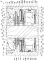
- FIGS. 1 to 6 The first embodiment will be described with reference to FIGS. 1 to 6.
- the upper side in FIGS. 1 to 3, 7 to 11, 23 and the left side in 12, 14, 17 to 20 are referred to as "upper”, and FIGS. 1 to 1 to FIG. 3.
- the lower side in FIGS. 7 to 11 and 23 and the right side in FIGS. 12, 14 and 17 to 20 will be described as “lower”.
- the shock absorber 1 of the first embodiment is a so-called monotube type hydraulic shock absorber, and includes a cylinder 2 in which an oil solution (not shown) as a working fluid is sealed.
- the cylinder 2 has a bottomed cylindrical shape.
- the cylinder 2 is an integrally molded product including a cylindrical body portion 11 and a bottom portion 12 formed on the lower side of the body portion 11 and closing the lower portion of the body portion 11.
- the shock absorber 1 has a compartment 15 and a piston 18 slidably provided inside the cylinder 2.
- the compartment 15 is provided between the piston 18 and the bottom 12 of the cylinder 2.
- the piston 18 defines two chambers, an upper chamber 19 and a lower chamber 20, in the cylinder 2, and the compartment 15 defines a lower chamber 20 and a gas chamber 16 in the cylinder 2. ..
- the piston 18 is slidably provided in the cylinder 2 and divides the inside of the cylinder 2 into an upper chamber 19 on one side and a lower chamber 20 on the other side.
- An oil liquid as a working fluid is sealed in the upper chamber 19 and the lower chamber 20 in the cylinder 2, and a gas is sealed in the gas chamber 16 in the cylinder 2.
- the shock absorber 1 includes a piston rod 21 in which one end side portion in the axial direction is arranged inside the cylinder 2 and is connected and fixed to the piston 18, and the other end side portion extends to the outside of the cylinder 2.
- the piston rod 21 penetrates the upper chamber 19 and does not penetrate the lower chamber 20. Therefore, the upper chamber 19 is a rod side chamber through which the piston rod 21 penetrates, and the lower chamber 20 is a bottom side chamber on the bottom 12 side of the cylinder 2.
- the piston 18 and the piston rod 21 move integrally.
- the piston 18 moves toward the upper chamber 19, and the piston rod 21 reduces the amount of protrusion from the cylinder 2.
- the piston 18 moves to the lower chamber 20 side.
- the rod guide 22 is fitted and fixed to the upper end opening side of the cylinder 2, and the seal member 23 is fitted to the upper side which is the outer side of the cylinder 2 with respect to the rod guide 22.
- the upper end portion of the cylinder 2 is crimped inward in the radial direction to form a locking portion 26, and the locking portion 26 and the rod guide 22 sandwich the seal member 23.
- a friction member 24 is provided between the rod guide 22 and the seal member 23.
- the rod guide 22, the friction member 24, and the seal member 23 all have an annular shape, and the piston rod 21 is slidably inserted inside each of the rod guide 22, the friction member 24, and the seal member 23. It extends from the inside of the cylinder 2 to the outside.
- One end of the piston rod 21 in the axial direction is fixed to the piston 18 inside the cylinder 2, and the other end of the piston rod 21 projects to the outside of the cylinder 2 via the rod guide 22, the friction member 24, and the seal member 23. There is.
- the rod guide 22 supports the piston rod 21 so as to be movable in the axial direction while restricting its radial movement, and guides the movement of the piston rod 21.
- the seal member 23 is in close contact with the cylinder 2 at its outer peripheral portion, and is in sliding contact with the outer peripheral portion of the piston rod 21 moving in the axial direction at its inner peripheral portion. As a result, the seal member 23 prevents the oil liquid in the cylinder 2 from leaking to the outside.
- the friction member 24 applies a frictional force to the piston rod 21.
- the piston rod 21 has a spindle portion 27 and a mounting shaft portion 28 having a diameter smaller than this.
- the spindle portion 27 is slidably fitted to the rod guide 22, the friction member 24, and the seal member 23, and the mounting shaft portion 28 is arranged in the cylinder 2 and connected to the piston 18 and the like. ..
- the end of the main shaft portion 27 on the mounting shaft portion 28 side is a shaft step portion 29 extending in the direction orthogonal to the axis.
- a passage notch 30 extending in the axial direction is formed on the outer peripheral portion of the mounting shaft portion 28 at an intermediate position in the axial direction, and a male screw 31 is formed at a tip position on the opposite side of the main shaft portion 27 in the axial direction.
- the passage cutout portion 30 is formed by, for example, notching the outer peripheral portion of the mounting shaft portion 28 in a plane on a plane parallel to the central axis of the mounting shaft portion 28.
- the passage cutout portion 30 can be formed in a so-called two-sided width shape at two positions different from each other by 180 degrees in the circumferential direction of the mounting shaft portion 28.
- the piston rod 21 is provided with an annular stopper member 32, a pair of supports 33, a coil spring 34, and a shock absorber 35 at a portion between the piston 18 of the spindle portion 27 and the rod guide 22. ..
- a piston rod 21 is inserted through the stopper member 32 on the inner peripheral side, and the stopper member 32 is crimped and fixed to the spindle portion 27.
- One support 33, the coil spring 34, the other support 33, and the cushioning body 35 are arranged in this order from the stopper member 32 side.
- the pair of supports 33 and the coil spring 34 have a piston rod 21 inserted inside, and are arranged between the stopper member 32 and the rod guide 22.
- a piston rod 21 is inserted inside the cushioning body 35, and the cushioning body 35 is arranged between the other support 33 and the rod guide 22.
- the protruding portion of the piston rod 21 from the cylinder 2 is arranged at the upper part and supported by the vehicle body, and the bottom portion 12 of the cylinder 2 is arranged at the lower part and connected to the wheel side.
- the cylinder 2 side may be supported by the vehicle body and the piston rod 21 may be connected to the wheel side.
- the piston 18 is an annular synthetic resin that is integrally mounted on the outer peripheral surface of the metal piston body 36 connected to the piston rod 21 and the outer peripheral surface of the piston body 36 and slides in the cylinder 2. It is composed of a sliding member 37 made of.
- the piston body 36 can communicate with a plurality of passage holes 38 capable of communicating the upper chamber 19 and the lower chamber 20 (only one place is shown in FIG. 2 due to the cross section), and the upper chamber 19 and the lower chamber 20 can communicate with each other.
- the plurality of passage holes 38 are formed at equal pitches with one passage hole 39 sandwiched between them in the circumferential direction of the piston body 36, and form half of the total number of the passage holes 38 and 39. ..
- the plurality of passage holes 38 have a crank shape having two bending points, and one side in the axial direction of the piston 18 (upper side in FIG. 2) is outward in the radial direction of the piston 18, and the other side in the axial direction of the piston 18 (upper side in FIG. 2).
- the lower side of FIG. 2) opens inward in the radial direction of the piston 18 rather than one side.
- the piston body 36 is formed with an annular groove 55 on the lower chamber 20 side in the axial direction to communicate a plurality of passage holes 38.
- a first damping force generating mechanism 41 that opens and closes passages in the annular groove 55 and a plurality of passage holes 38 to generate a damping force is provided.
- the passages in the plurality of passage holes 38 and the annular groove 55 move to the upper chamber 19 side of the piston 18, that is, upstream in the extension stroke. It is a passage on the extension side where the oil liquid flows out from the upper chamber 19 on the side to the lower chamber 20 on the downstream side.
- the first damping force generating mechanism 41 provided for the passages in the plurality of passage holes 38 and the annular groove 55 is from the passages in the plurality of passage holes 38 on the extension side and the passages in the annular groove 55 to the lower chamber 20. It is a damping force generation mechanism on the extension side that suppresses the flow of oil and liquid and generates damping force.
- the passage holes 39 which form the other half of the total number of the passage holes 38 and 39, are formed at equal pitches with one passage hole 38 sandwiched between them in the circumferential direction of the piston body 36.
- the plurality of passage holes 39 have a crank shape having two bending points, and the other side in the axial direction of the piston 18 (lower side in FIG. 2) is outward in the radial direction of the piston 18 and one side in the axial direction of the piston 18. (Upper side of FIG. 2) opens inward in the radial direction of the piston 18 with respect to the other side.
- the piston body 36 is formed with an annular groove 56 that allows a plurality of passage holes 39 to communicate with each other on the upper chamber 19 side in the axial direction.
- a first damping force generating mechanism 42 for opening and closing the passages in the plurality of passage holes 39 and the annular groove 56 to generate a damping force is provided.
- the passages in the plurality of passage holes 39 and the annular groove 56 move to the lower chamber 20 side of the piston 18, that is, upstream in the contraction stroke. It is a contraction-side passage through which the oil liquid flows from the lower chamber 20 on the side to the upper chamber 19 on the downstream side.
- the first damping force generating mechanism 42 provided for the passages in the plurality of passage holes 39 and the annular groove 56 is from the passages in the plurality of passage holes 39 on the contraction side and the passages in the annular groove 56 to the upper chamber 19. It is a damping force generation mechanism on the contraction side that suppresses the flow of oil and liquid and generates damping force.
- the piston body 36 has a substantially disk shape, and an insertion hole 44 into which the mounting shaft portion 28 of the piston rod 21 is inserted is formed in the center in the radial direction so as to penetrate in the axial direction.
- the insertion hole 44 includes a small diameter hole portion 45 on one side in the axial direction into which the mounting shaft portion 28 of the piston rod 21 is fitted, and a large diameter hole portion 46 on the other side in the axial direction having a diameter larger than that of the small diameter hole portion 45.
- the small diameter hole portion 45 is provided on the upper chamber 19 side in the axial direction, and the large diameter hole portion 46 is provided on the lower chamber 20 side in the axial direction.
- annular inner seat portion 47 is formed inside the piston body 36 in the radial direction from the opening on the lower chamber 20 side of the annular groove 55.
- a first damping force generating mechanism 41 is provided outside the opening on the lower chamber 20 side of the annular groove 55 in the radial direction of the piston body 36.
- An annular valve seat portion 48 forming a part thereof is formed.
- annular inner seat portion 49 is formed inside the piston body 36 in the radial direction from the opening on the upper chamber 19 side of the annular groove 56. .. Further, at the end of the piston body 36 on the upper chamber 19 side in the axial direction, a first damping force generating mechanism 42 is provided outside the opening of the annular groove 56 on the upper chamber 19 side in the radial direction of the piston body 36. An annular valve seat portion 50 forming a part thereof is formed.
- the insertion hole 44 of the piston body 36 is provided with a large-diameter hole portion 46 on the inner seat portion 47 side in the axial direction with respect to the small-diameter hole portion 45.
- the passage in the large-diameter hole portion 46 of the piston body 36 is always communicated with the piston rod passage portion 51 in the passage notch 30 of the piston rod 21 by overlapping the axial positions.
- the outer side in the radial direction of the valve seat portion 48 has a stepped shape having a lower axial height than the valve seat portion 48, and the lower chamber of the passage hole 39 on the contraction side is formed in this stepped portion.
- An opening on the 20 side is arranged.
- the radial outer side of the valve seat portion 50 has a stepped shape having a lower axial height than the valve seat portion 50, and the extension side passage is formed in this stepped portion.
- An opening on the upper chamber 19 side of the hole 38 is arranged.
- the first damping force generating mechanism 42 on the contraction side includes the valve seat portion 50 of the piston 18, and a plurality of pieces (specifically, two pieces) having the same inner diameter and the same outer diameter in order from the piston 18 side in the axial direction.
- one annular member 69 one annular member 69.
- the discs 62 to 68 and the annular member 69 are made of metal, and each has a perforated circular flat plate shape having a constant thickness to which the mounting shaft portion 28 of the piston rod 21 can be fitted.
- the disks 62 to 68 are plain disks (flat disks without protrusions).
- the disc 62 has an outer diameter larger than the outer diameter of the inner seat portion 49 of the piston 18 and a smaller diameter than the inner diameter of the valve seat portion 50, and is in constant contact with the inner seat portion 49.
- the disc 63 has an outer diameter larger than the outer diameter of the disc 62 and a smaller diameter than the inner diameter of the valve seat portion 50.
- the plurality of discs 64 have an outer diameter equivalent to the outer diameter of the valve seat portion 50 of the piston 18, and can be seated on the valve seat portion 50.
- the plurality of discs 65 have an outer diameter smaller than the outer diameter of the disc 64.
- the largest diameter of the plurality of discs 66 has an outer diameter smaller than the outer diameter of the disc 65.
- the disc 67 has an outer diameter smaller than the outer diameter of the smallest diameter disc 66 and is equivalent to the outer diameter of the inner seat portion 49 of the piston 18.
- the disc 68 has a larger diameter than the outer diameter of the smallest diameter disc 66, and has an outer diameter smaller than the outer diameter of the largest diameter disc 66.
- the annular member 69 has an outer diameter smaller than the outer diameter of the disc 68 and a larger diameter than the outer diameter of the shaft step portion 29 of the piston rod 21.
- the annular member 69 is thicker and more rigid than the discs 62 to 68, and is in contact with the shaft step portion 29.
- a plurality of discs 64, a plurality of discs 65, and a plurality of discs 66 constitute a contraction-side main valve 71 that can be attached to and detached from the valve seat portion 50.
- the passages in the plurality of passage holes 39 and the annular groove 56 are communicated with the upper chamber 19, and the flow of oil and liquid between the main valve 71 and the valve seat portion 50.
- the annular member 69, together with the disc 68, abuts on the main valve 71 to regulate deformation of the main valve 71 in the opening direction or more.
- the passages in the plurality of passage holes 39 and the annular groove 56 and the passages between the main valve 71 and the valve seat portion 50 appearing at the time of valve opening are moved in the lower chamber 20 side of the piston 18 in the cylinder 2.
- the first passage 72 on the contraction side through which the oil liquid flows out from the lower chamber 20 on the upstream side to the upper chamber 19 on the downstream side is configured.
- the contraction-side first damping force generating mechanism 42 that generates a damping force includes a main valve 71 and a valve seat portion 50, and is therefore provided in the first passage 72.
- the first passage 72 is formed in the piston 18 including the valve seat portion 50, and the oil liquid passes through when the piston rod 21 and the piston 18 move to the contraction side.
- the valve seat portion 50 and the main valve 71 in contact with the valve seat portion 50 are in contact with the upper chamber 19 and the lower chamber 20 even if they are in contact with each other.
- No fixed orifice is formed to communicate with each other. That is, the first damping force generating mechanism 42 on the contraction side does not communicate the upper chamber 19 and the lower chamber 20 if the valve seat portion 50 and the main valve 71 are in contact with each other over the entire circumference.
- the first passage 72 is not formed with a fixed orifice that constantly communicates the upper chamber 19 and the lower chamber 20, and is not a passage that constantly communicates the upper chamber 19 and the lower chamber 20.
- the first damping force generating mechanism 41 on the extension side includes the valve seat portion 48 of the piston 18, and one disc 82, one disc 83, and one disc in order from the piston 18 side in the axial direction.
- the disc 87 has a plurality of discs (specifically, two discs) having the same inner diameter and a smaller outer diameter as the distance from the piston 18 increases in the axial direction, and one disc 89.
- the discs 82 to 89 are made of metal, and are plain discs having a constant thickness and a perforated circular flat plate shape into which the mounting shaft portion 28 of the piston rod 21 can be fitted.
- the disc 82 has an outer diameter larger than the outer diameter of the inner seat portion 47 of the piston 18 and a smaller diameter than the inner diameter of the valve seat portion 48, and is in constant contact with the inner seat portion 47.
- the disk 82 has a passage in the annular groove 55 and a plurality of passage holes 38, a passage in the large-diameter hole portion 46 of the piston 18, and a piston in the passage notch 30 of the piston rod 21.
- a notch 90 that always communicates with the rod passage portion 51 is formed from an intermediate position outside the inner seat portion 47 in the radial direction to an inner peripheral edge portion.
- the notch 90 is formed during press molding of the disc 82.
- the notch 90 faces the large-diameter hole 46 of the piston 18 adjacent to each other.
- the disc 83 has the same outer diameter as the disc 82, and the notch portion like the disc 82 is not formed.
- the disc 84 has an outer diameter larger than the outer diameter of the disc 83 and a smaller diameter than the inner diameter
- the plurality of discs 85 have an outer diameter equivalent to the outer diameter of the valve seat portion 48 of the piston 18, and can be seated on the valve seat portion 48.
- the disc 86 has an outer diameter smaller than the outer diameter of the disc 85.
- the plurality of discs 87 have an outer diameter smaller than the outer diameter of the disc 86.
- the plurality of discs 88 have a large diameter, the outer diameter is smaller than the outer diameter of the disc 87.
- the disc 89 has a smaller diameter than the outer diameter of the smaller diameter of the plurality of discs 88, and has an outer diameter equivalent to the outer diameter of the inner seat portion 47 of the piston 18. As shown in FIG. 2, the disc 89 can be a common component having the same shape as the disc 67.
- the plurality of discs 88 are thicker and more rigid than the discs 85 to 87.
- a plurality of discs 85, a single disc 86, a plurality of discs 87, and a plurality of discs 88 constitute a main valve 91 on the extension side that can be detached and seated on the valve seat portion 48.
- the passages in the annular groove 55 and the plurality of passage holes 38 are communicated with the lower chamber 20, and the flow of oil and liquid between the main valve 91 and the valve seat portion 48. To generate damping force.
- the passages in the plurality of passage holes 38 and the annular groove 55 and the passages between the main valve 91 and the valve seat portion 48 that appear when the valve is opened are moved into the upper chamber 19 side of the piston 18 in the cylinder 2.
- the first passage 92 on the extension side through which the oil liquid flows out from the upper chamber 19 on the upstream side to the lower chamber 20 on the downstream side is formed.
- the extension-side first damping force generating mechanism 41 that generates a damping force includes a main valve 91 and a valve seat portion 48, and is therefore provided in the first passage 92.
- the first passage 92 is formed in the piston 18 including the valve seat portion 48, and the oil liquid passes through when the piston rod 21 and the piston 18 move to the extension side.
- the first damping force generating mechanism 41 on the extension side communicates the upper chamber 19 and the lower chamber 20 with both the valve seat portion 48 and the main valve 91 in contact with the valve seat portion 48 even when they are in contact with each other. No fixed orifice is formed. That is, the first damping force generating mechanism 41 on the extension side does not allow the upper chamber 19 and the lower chamber 20 to communicate with each other if the valve seat portion 48 and the main valve 91 are in contact with each other over the entire circumference.
- the first passage 92 is not formed with a fixed orifice that constantly communicates the upper chamber 19 and the lower chamber 20, and is not a passage that constantly communicates the upper chamber 19 and the lower chamber 20.
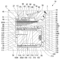
- one cap member 101 and one flexible disk are sequentially arranged from the first damping force generating mechanism 41 side.
- 100 flexible member, moving member
- a plurality of (specifically, two) disks 102, one sub-valve 107 (second sub-valve), and one O-ring 108 on the outer peripheral side are provided.
- One valve seat member 109, one sub-valve 110 (first sub-valve), one disc 111, one disc 113, and a plurality of (specifically two) annular members shown in FIG. 114 is provided by fitting the mounting shaft portion 28 of the piston rod 21 inside each of them.
- a male screw 31 is formed on the mounting shaft portion 28 of the piston rod 21 at a portion protruding from the annular member 114, and a nut 115 is screwed into the male screw 31.
- the nut 115 is in contact with the annular member 114.
- the flexible disc 100, the cap member 101, the discs 102, 111, 113, the sub valves 107, 110, the valve seat member 109, and the annular member 114 are all made of metal.
- the discs 102, 111, 113, the sub-valves 107, 110, and the annular member 114 all have a perforated circular flat plate shape having a constant thickness to which the mounting shaft portion 28 of the piston rod 21 can be fitted inside.
- the disks 102, 111, 113 and the sub valves 107, 110 are plain disks.
- the flexible disc 100, the cap member 101, and the valve seat member 109 all have an annular shape in which the mounting shaft portion 28 of the piston rod 21 can be fitted.
- the cap member 101 is a bottomed tubular integrally molded product, and is integrally formed by, for example, plastic working or cutting of a metal plate. As shown in FIG. 3, the cap member 101 extends from a perforated disk-shaped bottom portion 122 having a constant thickness and an outer peripheral edge portion of the bottom portion 122 while expanding the diameter in one axial direction of the bottom portion 122. It has a tapered portion 123 and a cylindrical tubular portion 124 extending in a direction opposite to the bottom portion 122 from an end edge portion on the side opposite to the bottom portion 122 of the intermediate tapered portion 123.
- the bottom portion 122 has a perforated disk shape in which the mounting shaft portion 28 of the piston rod 21 is fitted to the inner peripheral portion.
- the cap member 101 is positioned radially with respect to the piston rod 21 and is arranged coaxially.
- a plurality of passage holes 126 that penetrate the bottom portion 122 in the axial direction of the bottom portion 122 are formed in the bottom portion 122 between the inner peripheral portion and the outer peripheral portion.
- the plurality of passage holes 126 are arranged at equal distances from the center of the bottom portion 122 in the circumferential direction of the bottom portion 122, and are located on the outer peripheral portion side of the center between the inner peripheral portion and the outer peripheral portion of the bottom portion 122.
- the bottom portion 122 of the cap member 101 is arranged so as to be located closer to the piston 18 than the tubular portion 124 and is in contact with the disc 89, and is fitted to the mounting shaft portion 28 at the inner peripheral portion of the bottom portion 122. There is.
- the cap member 101 is thicker than the discs 85 to 88 and has a bottomed tubular shape, and has higher rigidity than the discs 85 to 88. Therefore, the cap member 101 abuts on the main valve 91 to regulate deformation of the main valve 91 composed of a plurality of discs 85 to 88 in the opening direction or more.
- the flexible disc 100 has a main body portion 301 and a disc protruding portion 302 (flexible member side protruding portion) protruding from the main body portion 301.
- the main body 301 has a perforated circular flat plate shape having a constant thickness when it is in a natural state before being assembled to the shock absorber 1, and the inner peripheral surface and the outer peripheral surface are coaxial.
- the disc projecting portion 302 projects from the main body portion 301 to one side of the main body portion 301 in the axial direction.
- the disc protruding portion 302 has an annular shape coaxial with the main body portion 301, and is formed on the outer peripheral surface side of the central position between the inner peripheral surface and the outer peripheral surface of the main body portion 301.
- the main body 301 can be fitted with the mounting shaft 28 of the piston rod 21 inside.
- the flexible disc 100 is positioned radially with respect to the piston rod 21 and is arranged coaxially.
- the flexible disc 100 is formed by press molding from a single plate material having a constant thickness, so that the main body portion 301 and the disc protruding portion 302 are integrally formed.
- the disc protruding portion 302 extends from the outer peripheral side of the main body portion 301 while tapering in one side in the axial direction, then folds back in the radial direction toward the other side in the axial direction, and tapers in the other side in the axial direction. It extends while reducing the diameter and joins the main body 301.
- the disc protrusion 302 has a tapered V-shape in which the cross-sectional shape of the flexible disc 100 on the surface including the central axis becomes narrower in the radial direction as the distance from the main body 301 in the axial direction increases.
- the disc protrusion 302 has an axisymmetric shape.
- the disc protrusion 302 has a circular shape in which the apex on the side opposite to the main body 301 in the axial direction of the flexible disc 100 is concentric with the inner peripheral portion and the outer peripheral portion of the flexible disc 100, and is higher than the main body 301. Is constant throughout the circumference.
- the flexible disc 100 is housed in the cap member 101, and the disc protrusion 302 is oriented so as to protrude from the main body 301 toward the bottom 122 in the axial direction, and abuts on the bottom 122 at the disc protrusion 302. .
- the disc 102 has an outer diameter smaller than the minimum inner diameter of the disc protrusion 302.
- the flexible disk 100 is sandwiched between the disk 102 and the bottom portion 122 on the inner peripheral side of the main body portion 301 in a state of being incorporated in the shock absorber 1.
- the main body portion 301 is elastically deformed in a tapered shape so as to be axially separated from the bottom portion 122 toward the outer side in the radial direction.
- the inner diameter of the tip surface that abuts on the bottom 122 of the disc protrusion 302 is more than twice the maximum distance from the center of the bottom 122 of the plurality of passage holes 126. Is also getting bigger.
- the annular disc protrusion 302 is arranged so as to surround the entire plurality of passage holes 126 in the radial direction of the bottom portion 122 and abuts on the bottom portion 122 over the entire circumference. ..
- the portion of the main body 301 that overlaps with the disc 102 is the inner peripheral side contact portion 303 that constantly contacts the disc 102 and the bottom portion 122 of the cap member 101 over the entire circumference.
- the outer diameter of the inner peripheral side contact portion 303 is smaller than twice the minimum distance from the center of the bottom portions 122 of the plurality of passage holes 126.
- the inner peripheral side contact portion 303 is arranged so as to surround the entire plurality of passage holes 126 inward in the radial direction of the bottom portion 122, and abuts on the bottom portion 122 over the entire circumference. ing.
- the main body 301 is the flexible portion 305 between the inner peripheral side contact portion 303, the inner peripheral side contact portion 303, and the disc protrusion 302. And the outer peripheral edge portion 306 that is radially outer than the disk protrusion 302.
- the outer peripheral edge portion 306 has an outer diameter smaller than the minimum inner diameter of the intermediate tapered portion 123 of the cap member 101, so that the flexible disc 100 comes into contact with the intermediate tapered portion 123 and the tubular portion 124. There is nothing to do.
- the flexible disc 100 is tapered so that the flexible portion 305 and the outer peripheral edge portion 306 are axially separated from the bottom portion 122 toward the outer side in the radial direction.
- the flexible disc 100 can be bent so that the flexible portion 305 approaches the bottom portion 122 or returns to the original state.
- the valve seat member 109 has a perforated disk shape in which a through hole 131 extending in the axial direction and penetrating in the thickness direction to insert the mounting shaft portion 28 is formed in the center in the radial direction.
- the through hole 131 includes a small diameter hole portion 132 on one side in the axial direction into which the mounting shaft portion 28 of the piston rod 21 is fitted, and a large diameter hole portion 133 on the other side in the axial direction having a larger diameter than the small diameter hole portion 132.
- the valve seat member 109 has an inner seat portion 134 forming an annular shape so as to surround the large diameter hole portion 133 at the end portion on the large diameter hole portion 133 side in the axial direction. It has a valve seat portion 135 that extends radially outward from the inner seat portion 134. Further, as shown in FIG. 4B, the valve seat member 109 has an inner seat portion 138 forming an annular shape so as to surround the small diameter hole portion 132 at the end portion on the small diameter hole portion 132 side opposite to the axial direction. It has a valve seat portion 139 that extends radially outward from the inner seat portion 138.
- the valve seat member 109 has a perforated disk-shaped main body 140 between the inner seat portion 134 and the valve seat portion 135 in the axial direction and the inner seat portion 138 and the valve seat portion 139.
- the inner seat portion 134 projects from the inner peripheral edge portion of the main body portion 140 on the axially large diameter hole portion 133 side to one side along the axial direction of the main body portion 140, and is a valve seat.
- the portion 135 also protrudes from the main body 140 to the same side as the inner seat 134 along the axial direction of the main body 140 on the radial outer side of the inner seat 134.
- the inner seat portion 134 and the valve seat portion 135 have a flat surface on the tip surface on the protruding side, that is, the tip surface on the side opposite to the main body portion 140, and are arranged in the same plane so as to spread in the direction orthogonal to the axis of the valve seat member 109. Has been done.
- the inner sheet portion 138 projects from the inner peripheral edge portion of the main body portion 140 on the side of the small diameter hole portion 132 in the axial direction to the side opposite to the inner seat portion 134 along the axial direction of the main body portion 140.
- the valve seat portion 139 also protrudes from the main body portion 140 to the same side as the inner seat portion 138 along the axial direction of the main body portion 140 on the radial outer side of the inner seat portion 138.
- the inner seat portion 138 and the valve seat portion 139 have a flat surface on the tip surface on the protruding side, that is, the tip surface on the side opposite to the main body portion 140, and are arranged in the same plane so as to spread in the direction orthogonal to the axis of the valve seat member 109. Has been done.
- the inner sheet portions 134 and 138 have the same outer diameter.
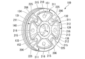
- valve seat portion 135 is a petal-shaped deformed seat, and has a plurality of, specifically, four valve seat constituent portions 201.
- These valve seat components 201 have the same shape and are arranged at equal intervals in the circumferential direction of the valve seat member 109.
- the inner seat portion 134 has an annular shape centered on the central axis of the valve seat member 109.
- the valve seat component 201 connects a pair of extension portions 202 that extend radially outward from the inner seat portion 134 and ends of the pair of extension portions 202 that are opposite to the inner seat portion 134. It has a connecting portion 203 and.
- the pair of extending portions 202 are all linear, and are mirror-symmetrical with respect to the surface including the central axis of the valve seat member 109.
- the pair of extending portions 202 are arranged so as to be perpendicular to each other when viewed in the axial direction of the valve seat member 109.
- the connecting portion 203 has an arc shape centered on the central axis of the valve seat member 109.
- Aisle recess 205 that is surrounded by the valve seat component 201 and a part of the inner seat 134 that connects the pair of extending portions 202 to each other and is recessed in the axial direction of the valve seat member 109 from the tip surface on the protruding side thereof. Is formed.
- the bottom surface of the passage recess 205 is formed by the main body 140.
- Aisle recess 205 is formed inside all valve seat components 201. All the passage recesses 205 are formed at positions equidistant from the central axis of the valve seat member 109, and are formed at equal intervals in the circumferential direction of the valve seat member 109.
- a passage hole 206 that penetrates the valve seat member 109 in the axial direction is formed by penetrating the main body 140 in the axial direction.
- the passage hole 206 is a linear hole parallel to the central axis of the valve seat member 109.
- Passage holes 206 are formed on the bottom surfaces of all passage recesses 205. All the passage holes 206 are formed at positions equidistant from the central axis of the valve seat member 109, and are formed at equal intervals in the circumferential direction of the valve seat member 109.
- the adjacent extension portions 202 of the valve seat component 201 arranged adjacent to each other in the circumferential direction of the valve seat member 109 are separated from each other in the circumferential direction of the valve seat member 109 and are parallel to each other. It is parallel to the radial line passing through the central axis of 109.
- the extension portions 202 on the side far from the circumferential direction of the valve seat component 201 arranged adjacent to each other in the circumferential direction of the valve seat member 109 are in the same straight line parallel to the radial line passing through the central axis of the valve seat member 109. It is arranged on the line.
- valve seat portion 139 is also a petal-shaped deformed seat, and has a plurality of, specifically, four valve seat constituent portions 211. These valve seat constituents 211 have the same shape and are arranged at equal intervals in the circumferential direction of the valve seat member 109.
- the valve seat component 211 has the same shape as the valve seat component 201.
- the inner seat portion 138 has an annular shape centered on the central axis of the valve seat member 109.
- the valve seat component 211 connects a pair of extending portions 212 extending radially outward from the inner seat portion 138 and ends of the pair of extending portions 212 on the opposite side of the inner seat portion 138. It has a connecting portion 213 and.
- Each of the pair of extending portions 212 is linear, and is mirror-symmetrical with respect to the surface including the central axis of the valve seat member 109.
- the pair of extending portions 212 are arranged so as to be perpendicular to each other when viewed in the axial direction of the valve seat member 109.
- the connecting portion 213 has an arc shape centered on the central axis of the valve seat member 109.
- the outer diameter of the outer edge portion arranged on the same circle of all the connecting portions 213 is the same as the outer diameter of the outer edge portion arranged on the same circle of all the connecting portions 203, and all the connecting portions 213.
- the inner diameter of the inner edge portion arranged on the same circle is the same as the inner diameter of the inner edge portion arranged on the same circle of all the connecting portions 203.
- Aisle recess 215 that is surrounded by the valve seat component 211 and a part of the inner seat 138 that connects the pair of extending portions 212 to each other and is recessed in the axial direction from the tip surface on the protruding side of the valve seat member 109. Is formed.
- the bottom surface of the passage recess 215 is formed by the main body 140.
- Aisle recesses 215 are formed inside all valve seat components 211. All the passage recesses 215 are formed at positions equidistant from the central axis of the valve seat member 109, and are formed at equal intervals in the circumferential direction of the valve seat member 109.
- a passage hole 216 that penetrates the valve seat member 109 in the axial direction is formed by penetrating the main body 140 in the axial direction.
- the passage hole 216 is a linear hole parallel to the central axis of the valve seat member 109.
- Passage holes 216 are formed on the bottom surfaces of all passage recesses 215. All the passage holes 216 are formed at positions equidistant from the central axis of the valve seat member 109, and are formed at equal intervals in the circumferential direction of the valve seat member 109.
- the adjacent extending portions 212 of the valve seat constituent portions 211 arranged adjacent to each other in the circumferential direction of the valve seat member 109 are separated from each other in the circumferential direction of the valve seat member 109 and are parallel to each other. It is parallel to the radial line passing through the central axis of 109.
- the extension portions 212 on the side farther in the circumferential direction of the valve seat component 211 arranged adjacent to each other in the circumferential direction of the valve seat member 109 are in the same straight line parallel to the radial line passing through the central axis of the valve seat member 109. It is arranged on the line.
- the arrangement pitch of the valve seat members 109 of the plurality of valve seat constituents 201 in the circumferential direction and the arrangement pitch of the valve seat members 109 of the plurality of valve seat constituents 211 in the circumferential direction are the same, and the valve seat configuration.
- the section 201 and the valve seat component section 211 are offset from each other by half a pitch.
- the central position of the valve seat component 211 is arranged at the center position between the valve seat component 201 and the valve seat component 201 adjacent to each other in the circumferential direction of the valve seat member 109, and conversely, the valve seat member
- the central position of the valve seat component 201 is arranged at the center position between the valve seat component 211 and the valve seat component 211 that are adjacent to each other in the circumferential direction of 109.
- All passage recesses 205 and all passage recesses 215 are formed at equidistant positions from the central axis of the valve seat member 109, and the passage recesses 205 and passage recesses 215 are alternately staggered in the circumferential direction of the valve seat member 109. It is arranged in a shape. All the passage holes 206 and all the passage holes 216 are formed at equidistant positions from the central axis of the valve seat member 109, and the passage holes 206 and the passage holes 216 are alternately formed on the same circumference at equal intervals. It is provided.
- the passage hole 206 is arranged between the valve seat component 211 and the valve seat component 211 adjacent to each other in the circumferential direction of the valve seat member 109, and thus the range of the valve seat 139. It is located outside the.
- the passage hole 216 is arranged between the valve seat component 201 and the valve seat component 201 that are adjacent to each other in the circumferential direction of the valve seat member 109, and thus the range of the valve seat 135. It is located outside the.
- a passage groove 221 that crosses the inner seat portion 134 in the radial direction is formed on the side of the large diameter hole portion 133 in the axial direction over the inner seat portion 134 and the main body portion 140.
- the passage groove 221 is recessed in the axial direction of the valve seat member 109 from the tip surface of the inner seat portion 134 opposite to the main body portion 140, and is further recessed than the end surface of the main body portion 140 on the inner seat portion 134 side. Has been done.
- the passage groove 221 is provided along the radial line passing through the center of the valve seat member 109, and is a passage hole 216 that opens between the valve seat component 201 and the valve seat component 201.
- Passage grooves 221 are provided for all passage holes 216.
- a plurality of, specifically four, passage grooves 221 are provided at equal intervals in the circumferential direction of the valve seat member 109 with the positions aligned in the radial direction of the valve seat member 109.
- the inner sheet portion 134 is formed intermittently in the circumferential direction by forming the passage groove 221.
- the passage hole 216 and the passage recess 215 through which the passage hole 216 opens form a first passage portion 151 provided in the valve seat member 109.
- the valve seat member 109 is provided with a plurality of first passage portions 151, specifically, four locations, which are aligned in the radial direction of the valve seat member 109 and are provided at equal intervals in the circumferential direction of the valve seat member 109.
- the valve seat member 109 is provided with a plurality of first passage portions 151 on the same circumference at equal intervals.
- the passage groove 221 forms a radial passage 222 extending in the radial direction toward the first passage portion 151.
- the valve seat member 109 is provided with a plurality of radial passages 222, specifically, four locations, which are aligned in the radial direction of the valve seat member 109 and are provided at equal intervals in the circumferential direction of the valve seat member 109.
- the valve seat member 109 is formed with a passage groove 225 on the side of the small diameter hole portion 132 in the axial direction of the main body portion 140.
- the passage groove 225 is formed so as to be recessed in the axial direction of the valve seat member 109 from the end surface of the main body portion 140 on the inner seat portion 138 side.
- the passage groove 225 is provided along the radial line passing through the center of the valve seat member 109, and is a passage hole 206 opened between the valve seat constituent portion 211 and the valve seat constituent portion 211.
- the valve seat member 109 extends outward in the radial direction and comes out to the outer peripheral surface of the main body 140.
- the passage hole 206 is open to the bottom surface of the passage groove 225.
- Passage grooves 225 are provided for all passage holes 206.
- a plurality of passage grooves 225, specifically four places, are provided at equal intervals in the circumferential direction of the valve seat member 109 by aligning the positions of the valve seat member 109 in the radial direction.
- the passage hole 206 and the passage recess 205 through which the passage hole 206 opens form a second passage portion 152 provided in the valve seat member 109.
- the valve seat member 109 is provided with a plurality of second passage portions 152, specifically, four locations, which are aligned in the radial direction of the valve seat member 109 and are provided at equal intervals in the circumferential direction of the valve seat member 109.
- the valve seat member 109 is provided with a plurality of second passage portions 152 on the same circumference at equal intervals.
- a plurality of first passage portions 151 and a plurality of second passage portions 152 are provided on the valve seat member 109 to form a valve seat member passage portion 150 through which oil liquid flows.
- the valve seat member passage portion 150 has a first passage portion 151 and a second passage portion 152, and the first passage portion 151 and the second passage portion 152 are alternately arranged on the same circumference at equal intervals. It is provided.
- the valve seat member 109 is formed with an annular seal groove 145 that is recessed inward in the radial direction at an axially intermediate position on the outer peripheral portion.
- An O-ring 108 is arranged in the seal groove 145.
- the valve seat member 109 is fitted to the tubular portion 124 of the cap member 101 at the outer peripheral portion in a state where the inner seat portion 138 and the valve seat portion 139 are directed to the side opposite to the bottom portion 122, and the cap member 101 It is provided inside. In this state, the O-ring 108 seals the gap between the tubular portion 124 of the cap member 101 and the valve seat member 109.
- the cap member 101, the O-ring 108, and the valve seat member 109 form a cap chamber 146 inside the cap member 101.
- the cap chamber 146 is provided between the bottom portion 122 of the cap member 101 and the valve seat member 109.
- the flexible disc 100, the plurality of discs 102, and the sub valve 107 are provided in the cap chamber 146.
- the flexible disc 100 is provided between the sub valve 107 in the cap chamber 146 and the bottom 122 of the cap member 101.
- the flexible disc 100 is constantly in contact with the bottom portion 122 of the cap member 101 over the entire circumference so that the disc protruding portion 302 surrounds the entire plurality of passage holes 126 outward in the radial direction of the bottom portion 122. Further, the flexible disk 100 always contacts the bottom portion 122 of the cap member 101 over the entire circumference so that the inner peripheral side contact portion 303 surrounds the entire plurality of passage holes 126 inward in the radial direction of the bottom portion 122. ..
- the cap chamber 146 has an intermediate chamber 147 on the sub valve 107 side of the flexible disc 100 and a communication chamber 149 (volume chamber) on the plurality of passage holes 126 side of the flexible disc 100. It is divided into.
- the communication room 149 is constantly connected to the communication passage 148 in the plurality of passage holes 126.
- the intermediate chamber 147 is cut off from the communication passage 148 by the flexible disc 100.
- a flexible flexible disk 100 that closes the communication passage 148 is provided between the sub valve 107 and the bottom portion 122 of the cap member 101.
- an intermediate chamber 147 is formed between the flexible disc 100 and the sub valve 107 so that the flexible disc 100 cuts off the communication with the communication passage 148.
- the volume of the intermediate chamber 147 changes as the flexible disc 100 bends. That is, the bending of the flexible disc 100 causes the intermediate chamber 147 to function as an accumulator.
- the volume of the communication chamber 149 decreases to absorb the increase in the volume of the intermediate chamber 147 to discharge the oil liquid, or the volume increases to absorb the decrease in the volume of the intermediate chamber 147 and the oil liquid flows in. Let me do it. This prevents the deformation of the flexible disc 100 from being hindered by the oil solution in the communication chamber 149.
- the annular valve seat member 109 and the bottomed tubular cap member 101 are arranged in the lower chamber 20 which is one of the upper chamber 19 and the lower chamber 20.
- the valve seat portion 135 is arranged on the cap chamber 146 side
- the valve seat portion 139 is arranged on the lower chamber 20 side.
- the valve seat member 109 divides the intermediate chamber 147 and the lower chamber 20 of the cap chamber 146, and is provided so as to face both the intermediate chamber 147 and the lower chamber 20.
- the plurality of passage grooves 225 are provided facing the lower chamber 20, and the plurality of second passage portions 152 are constantly communicated with the lower chamber 20 via the passages in the plurality of passage grooves 225.
- the communication passage 148 formed in the bottom portion 122 of the cap member 101 always communicates with the lower chamber 20 which is one of the upper chamber 19 and the lower chamber 20.
- the radial passage 222 in the passage groove 221 that opens to the first passage portion 151 of the valve seat member 109 is always in communication with the intermediate chamber 147, and the inside of the intermediate chamber 147 and the large diameter hole portion 133 of the valve seat member 109.
- the passage inside and the piston rod passage portion 51 in the passage cutout portion 30 of the piston rod 21 are always in communication with each other. Therefore, the intermediate chamber 147 includes a radial passage 222 in the passage groove 221 of the valve seat member 109, a passage in the large-diameter hole portion 133 of the valve seat member 109, and a piston rod passage in the passage notch 30 of the piston rod 21.
- the upper chamber is provided through a passage in the large-diameter hole 46 of the portion 51 and the piston 18, a passage in the notch 90 of the disk 82, and a passage in the annular groove 55 of the piston 18 and in the plurality of passage holes 38. It is always in contact with 19.
- the disc 102 has an outer diameter equivalent to the outer diameter of the inner sheet portion 47.
- the sub valve 107 has a disc shape, and as shown in FIG. 2, has an outer diameter equivalent to the outer diameter of the valve seat portion 135 of the valve seat member 109, and is constantly in contact with the inner seat portion 134 to provide the valve seat. It is possible to take off and sit on the part 135.
- the sub-valve 107 closes all the second aisle portions 152 by being seated on the entire valve seat portion 135. Further, the sub-valve 107 closes the second aisle portion 152 inside the valve seat constituent portion 201 by being seated on the entire valve seat constituent portion 201 of any of the valve seat portions 135 shown in FIG. 4A. ..
- the sub-valve 107 that can be detached and seated in the valve seat portion 135 is provided in the cap chamber 146, and is separated from the valve seat portion 135 in the cap chamber 146 to form a plurality of second valves.
- the passage portion 152 and the intermediate chamber 147 of the cap chamber 146 are communicated with each other, and the lower chamber 20 is communicated with the upper chamber 19.
- the sub valve 107 suppresses the flow of the oil liquid with the valve seat portion 135 to generate a damping force.
- the sub-valve 107 is an inflow valve that opens when oil liquid flows into the intermediate chamber 147 from the lower chamber 20 through the plurality of second passage portions 152, and is a second passage portion from the intermediate chamber 147 to the lower chamber 20.
- the passage hole 216 constituting the first passage portion 151 is opened to the outside of the range of the valve seat portion 135 in the valve seat member 109, and therefore is seated in the valve seat portion 135. It always communicates with the intermediate chamber 147 regardless of the sub valve 107 shown in FIG.
- the passage in the notch 90 of the disk 82 and the passage in the annular groove 55 of the piston 18 and in the plurality of passage holes 38 become the upstream side in the cylinder 2 by moving the piston 18 toward the lower chamber 20 side.
- a second passage 172 is formed in which the oil liquid flows out from the lower chamber 20 to the upper chamber 19 on the downstream side.
- the second passage 172 is a passage on the contraction side in which the oil liquid flows from the lower chamber 20 on the upstream side to the upper chamber 19 on the downstream side in the movement of the piston 18 to the lower chamber 20 side, that is, in the contraction stroke.
- the second passage 172 includes a piston rod passage portion 51 in the passage notch 30 formed by cutting out the piston rod 21, in other words, a part thereof is formed by cutting out the piston rod 21. ..
- a part thereof is formed by cutting out the piston rod 21.
- one end is opened in the passage in the large diameter hole portion 133 of the valve seat member 109, and the other end is opened in the passage in the large diameter hole portion 46 of the piston 18.
- the piston rod passage portion 51 may be formed by penetrating the inside of the piston rod 21 in a hole shape. Therefore, the second passage 172 has a piston rod passage portion 51 formed by notching or penetrating the piston rod 21.
- a sub-valve 107, a valve seat portion 135, a plurality of discs 102, a flexible disc 100, and a cap member 101 are provided in the second passage 172 on the contraction side, and the second passage 172 is opened and closed. It constitutes a second damping force generation mechanism 173 on the contraction side that suppresses the flow of oil liquid from the second passage 172 to the upper chamber 19 to generate a damping force.
- the valve seat portion 135 of the second damping force generating mechanism 173 is provided on the valve seat member 109.
- the sub-valve 107 constituting the second damping force generating mechanism 173 on the contraction side is a sub-valve on the contraction side.
- the passage in the notch 90 of the disk 82 is the narrowest in the portion where the flow path cross-sectional area is fixed, and the flow path cross-sectional area is the narrowest.
- an orifice 175 in the second passage 172 narrower than its upstream and downstream sides.
- the orifice 175 is arranged on the downstream side of the sub valve 107 of the flow of the oil liquid when the sub valve 107 is opened and the oil liquid flows in the second passage 172.
- the orifice 175 is formed by cutting out a disc 82 that abuts on the piston 18 of the first damping force generating mechanism 41.
- the second damping force generating mechanism 173 on the contraction side communicates the upper chamber 19 and the lower chamber 20 with both the valve seat portion 135 and the sub-valve 107 in contact with the valve seat portion 135 even when they are in contact with each other. Is not formed. That is, the second damping force generating mechanism 173 on the contraction side does not communicate the upper chamber 19 and the lower chamber 20 if the valve seat portion 135 and the sub valve 107 are in contact with each other over the entire circumference.
- the second passage 172 is not formed with a fixed orifice that constantly communicates the upper chamber 19 and the lower chamber 20, and is not a passage that constantly communicates the upper chamber 19 and the lower chamber 20.
- the contraction-side second passage 172 that can communicate the upper chamber 19 and the lower chamber 20 is parallel to the first passage 72 that is the contraction-side passage that can also communicate the upper chamber 19 and the lower chamber 20.
- a first damping force generating mechanism 42 is provided in the first passage 72, and a second damping force generating mechanism 173 is provided in the second passage 172. Therefore, the first damping force generating mechanism 42 and the second damping force generating mechanism 173 on the contraction side are arranged in parallel.
- the sub-valve 110 has a disc shape and has an outer diameter equivalent to the outer diameter of the valve seat portion 139 of the valve seat member 109, and is constantly in contact with the inner seat portion 138 to be in contact with the valve seat. It is possible to take off and sit on the part 139.
- the sub-valve 110 closes all the first aisle portions 151 by being seated on the entire valve seat portion 139. Further, the sub-valve 110 closes the first passage portion 151 inside the valve seat constituent portion 211 by being seated on the entire valve seat constituent portion 211 of the valve seat portion 139 shown in FIG. 4B. ..
- the sub valve 110 can be a common component having the same shape as the sub valve 107.
- the outer diameter of the disk 111 is smaller than the outer diameter of the sub valve 110, and is equivalent to the outer diameter of the inner seat portion 138.
- the sub-valve 110 is provided in the lower chamber 20 and allows the intermediate chamber 147 and the lower chamber 20 to communicate with each other by being separated from the valve seat portion 139. At this time, the sub valve 110 suppresses the flow of the oil liquid with the valve seat portion 139 to generate a damping force.
- the sub-valve 110 is a discharge valve that opens when the oil liquid is discharged from the intermediate chamber 147 to the lower chamber 20 through the plurality of first passage portions 151 of the valve seat member 109, and is opened from the lower chamber 20 to the intermediate chamber 147. This is a check valve that regulates the inflow of oil liquid through the first passage portion 151.
- the passage hole 206 constituting the second passage portion 152 is open to the outside of the range of the valve seat portion 139 in the valve seat member 109, and therefore the valve seat shown in FIG. It always communicates with the lower chamber 20 regardless of the sub valve 110 seated in the portion 139.
- the passage between the first passage portion 151 and the sub-valve 110 and the valve seat portion 139 that appear when the valve is opened is downstream from the upper chamber 19 which is the upstream side in the cylinder 2 due to the movement of the piston 18 to the upper chamber 19 side.
- a second passage 182 through which the oil liquid flows out to the lower chamber 20 on the side is configured.
- the second passage 182 is a passage on the extension side where the oil liquid flows out from the upper chamber 19 on the upstream side to the lower chamber 20 on the downstream side in the movement of the piston 18 to the upper chamber 19 side, that is, in the extension stroke.
- the second passage 182 includes a piston rod passage portion 51 in the passage notch 30 formed by cutting out the piston rod 21, in other words, a part thereof is formed by cutting out the piston rod 21. ..
- a cap member 101, a sub valve 110, a valve seat portion 139, discs 111, 113, and an annular member 114 are provided in the second passage 182 on the extension side, and the second passage 182 is opened and closed to open and close the second passage. It constitutes a second damping force generation mechanism 183 on the extension side that suppresses the flow of oil liquid from the passage 182 to the lower chamber 20 to generate a damping force.
- the valve seat portion 139 is provided on the valve seat member 109.
- the sub-valve 110 constituting the extension-side second damping force generation mechanism 183 is an extension-side sub-valve.
- the communication chamber 149 communicating with the lower chamber 20 is arranged in parallel with the second passage 172 shown in FIG. 2 and the second passage 182 shown in FIGS. 2 and 3.
- the second damping force generation mechanism 173, 183 has a volume variable mechanism 185 that can change the volume of the communication chamber 149.
- the volume variable mechanism 185 is composed of a flexible disc 100, a bottom 122 of a cap member 101, a communication chamber 149, and a communication passage 148.
- the flexible disk 100 is changed so as to reduce the volume of the communication chamber 149 by deforming and moving toward the bottom 122, and increasing the volume of the communication chamber 149 by deforming and moving away from the bottom 122. Change to.
- the passage in the notch 90 of the disk 82 shown in FIG. 2 is the narrowest among the portions having the fixed flow path cross-sectional area.
- the cross-sectional area of the flow path becomes narrower than that on the upstream side and the downstream side, and the orifice 175 is also formed in the second passage 182.
- the orifice 175 is common to the second passages 172 and 182.
- the orifice 175 is arranged on the upstream side of the sub valve 110 of the flow of the oil liquid when the sub valve 110 is opened and the oil liquid flows in the second passage 182.
- the orifice 175 may be arranged on the downstream side of the sub valve 110 of the flow of the oil liquid when the sub valve 110 is opened and the oil liquid flows in the second passage 182.
- the sub valve 110 and the above-mentioned sub valve 107 open and close independently.
- the second damping force generating mechanism 183 on the extension side is a fixed orifice that communicates the upper chamber 19 and the lower chamber 20 with both the valve seat portion 139 and the sub valve 110 in contact with the valve seat portion 139 even if they are in contact with each other. Is not formed. That is, the second damping force generating mechanism 183 on the extension side does not communicate the upper chamber 19 and the lower chamber 20 as long as the valve seat portion 139 and the sub valve 110 are in contact with each other over the entire circumference.
- the second passage 182 is not formed with a fixed orifice that constantly communicates the upper chamber 19 and the lower chamber 20, and is not a passage that constantly communicates the upper chamber 19 and the lower chamber 20.
- the shock absorber 1 In the shock absorber 1, the upper chamber 19 and the lower chamber 20 have the first damping force generating mechanisms 41 and 42 and the second damping force generating mechanism 1733 as the flow for passing the oil liquid in the axial direction at least in the piston 18. Communication is possible only via 183. Therefore, the shock absorber 1 is not provided with a fixed orifice that constantly communicates the upper chamber 19 and the lower chamber 20 at least on the passage of the oil liquid that passes through the piston 18 in the axial direction. Since the shock absorber 1 is a monotube type, it is not provided with a fixed orifice that constantly communicates the upper chamber 19 and the lower chamber 20 as a whole.
- the extension-side second passage 182 that can communicate the upper chamber 19 and the lower chamber 20 is the extension-side passage 92 that can also communicate the upper chamber 19 and the lower chamber 20, and the upper chamber 19 side. Except for the passages in the annular groove 55 and the plurality of passage holes 38, the first passage 92 has a first damping force generating mechanism 41, and the second passage 182 has a second damping force. Each generation mechanism 183 is provided. Therefore, the first damping force generating mechanism 41 and the second damping force generating mechanism 183 on the extension side are arranged in parallel.
- the second damping force generating mechanism 173, 183 is a sub valve 110 provided on one side of the valve seat member 109 and the valve seat member passage portion 150, which is a portion of the second passages 172 and 182 provided on the valve seat member 109.
- a sub-valve 107 provided on the other side of the valve seat member passage portion 150, and a bottomed tubular cap member 101 provided between the piston 18 and the valve seat member 109 in the second passages 172 and 182 are provided.
- the valve seat member 109 is provided in the cap member 101
- the sub valve 110 is provided on the lower chamber 20 side of the valve seat member 109
- the sub valve 107 is between the bottom portion 122 of the cap member 101 and the valve seat member 109. It is provided in the cap chamber 146 of.
- the valve seat member 109 is provided with a radial passage 222 that communicates with the piston rod passage portion 51 and extends radially toward the extension-side first passage portion 151.
- the annular member 69, the disc 68, the disc 67, and a plurality of discs 66 are inserted into the shaft step portion 29 while inserting the mounting shaft portion 28 of the piston rod 21.
- the plurality of discs 65, the plurality of discs 64, the discs 63, the plurality of discs 62, and the piston 18 are stacked in this order.
- the piston 18 is oriented so that the small diameter hole portion 45 is located on the shaft step portion 29 side.
- the piston 18, the disc 82, the disc 83, the disc 84, the plurality of discs 85, the disc 86, the plurality of discs 87, and the plurality of discs are inserted.
- the disc 88, the disc 89, and the cap member 101 are stacked in this order. At this time, the cap member 101 comes into contact with the disc 89 with the bottom portion 122 oriented toward the piston 18.
- valve seat member 109 in which the flexible disc 100, a plurality of discs 102, the sub valve 107, and the O-ring 108 are mounted on the bottom 122 of the cap member 101 while inserting the mounting shaft portions 28, respectively. And are layered in order.
- the flexible disc 100 is oriented so that the disc protrusion 302 projects from the main body 301 toward the bottom 122 side, and the disc protrusion 302 abuts on the bottom 122 and abuts on the inner peripheral side.
- the unit 303 abuts on the disc 102.
- valve seat member 109 is oriented so that the inner seat portion 134 and the valve seat portion 135 are located on the sub-valve 107 side, and the outer peripheral portion and the O-ring 108 are attached to the cap member 101. It is fitted to the tubular portion 124.
- the sub valve 110, the disc 111, the disc 113, and the plurality of annular members 114 are sequentially stacked on the valve seat member 109 while inserting the mounting shaft portions 28, respectively.
- the nut 115 is screwed into the male screw 31 of the piston rod 21 protruding from the annular member 114, and the nut 115 and the shaft step portion 29 clamp at least the inner peripheral side thereof in the axial direction.
- the main valve 71 is clamped to the inner seat portion 49 and the disc 67 of the piston 18 via the discs 62 and 63 on the inner peripheral side, and abuts on the valve seat portion 50 of the piston 18 over the entire circumference. Further, in this state, the main valve 91 is clamped to the inner seat portion 47 and the disc 89 of the piston 18 via the discs 82 to 84 on the inner peripheral side, and is in contact with the valve seat portion 48 of the piston 18 over the entire circumference. Get in touch.
- the flexible disc 100 abuts on the bottom portion 122 at the disc protruding portion 302 while elastically deforming, and the inner peripheral side abutting portion 303 meets the bottom portion 122 of the cap member 101. It is clamped to the disc 102. Further, in this state, as shown in FIG. 2, the inner peripheral side of the sub valve 107 is clamped to the inner seat portion 134 of the valve seat member 109 and the disc 102, and the entire valve seat portion 135 of the valve seat member 109 is clamped. Contact over the circumference.
- the sub valve 110 is clamped to the inner seat portion 138 of the valve seat member 109 and the disc 111 on the inner peripheral side, and abuts on the valve seat portion 139 of the valve seat member 109 over the entire circumference.
- the flexible disc 100 abuts on the bottom portion 122 at the disc protrusion 302, and when the inner peripheral side contact portion 303 is clamped to the bottom portion 122 and the disc 102 of the cap member 101, the disc protrudes.
- the portion 302 comes into contact with the bottom portion 122 of the cap member 101 over the entire circumference in a state where the preload corresponding to the height is applied.
- the sub-valve 107 bends in the direction of the flexible disc 100 when the valve is opened, but a sufficient gap is provided between the sub-valve 107 and the flexible disc 100, and the sub-valve 107 lifts the maximum. It is designed so that it does not come into contact with the flexible disc 100 even at times.
- the main valve 91 of the first damping force generating mechanism 41 is the second damping force generating mechanism 183.
- the rigidity is higher and the valve opening pressure is higher than that of the sub valve 110. Therefore, in the extension stroke, the second damping force generating mechanism 183 opens with the first damping force generating mechanism 41 closed in the extremely low speed region where the piston speed is lower than the predetermined value. Further, in the normal speed region where the piston speed is equal to or higher than this predetermined value, both the first damping force generating mechanism 41 and the second damping force generating mechanism 183 are opened.
- the sub-valve 110 is an extremely low-speed valve that opens in a region where the piston speed is extremely low and generates a damping force.
- the intermediate chamber 147 It flows into the intermediate chamber 147 via the passage in the large-diameter hole portion 133 of the valve seat member 109 and the valve seat member 109 and the radial passage 222 in the passage groove 221 of the valve seat member 109. As a result, the intermediate chamber 147 is boosted. Therefore, in the volume variable mechanism 185 shown in FIG. 3, the flexible portion 305 of the flexible disc 100 bends toward the bottom 122 side to increase the capacity of the intermediate chamber 147, thereby increasing the pressure in the intermediate chamber 147. It will be suppressed. At this time, since the flexible disc 100 bends and moves toward the bottom 122 side, the volume variable mechanism 185 reduces the volume of the communication chamber 149.
- the amount of oil liquid flowing from the upper chamber 19 to the intermediate chamber 147 as described above becomes large, so that the flexible disk
- the 100 is greatly deformed and comes into contact with the bottom portion 122 of the cap member 101 at the flexible portion 305, and the contact area thereof becomes large.
- the contact area of the flexible disc 100 with the bottom portion 122 increases in this way, the amount of bending of the flexible disc 100 is limited, and the flexible disc 100 does not bend due to the addition of a certain amount of differential pressure.
- the pressure is increased to the state where the second damping force generating mechanism 183 is opened in the same state as when the flexible disc 100 and the communication passage 148 are not present.
- neither the first damping force generating mechanism 41, 42 nor the second damping force generating mechanism 173, 183 has a fixed orifice that constantly communicates the upper chamber 19 and the lower chamber 20, so the solid line is shown in FIG.
- the damping force suddenly rises in the extension stroke when the piston speed is less than the first predetermined value v1 when the second damping force generation mechanism 183 opens.
- the first The second damping force generating mechanism 183 opens with the damping force generating mechanism 41 closed.
- the sub-valve 110 is separated from the valve seat portion 139, and the upper chamber 19 and the lower chamber 20 are communicated with each other through the second passage 182 on the extension side. Therefore, the oil liquid in the upper chamber 19 is a passage in the plurality of passage holes 38 of the piston 18, a passage in the annular groove 55, a passage in the orifice 175, a passage in the large diameter hole portion 46 of the piston 18, and a passage notch in the piston rod 21.
- the damping force of the valve characteristic (the characteristic in which the damping force is substantially proportional to the piston speed) can be obtained even in the extremely low speed region where the piston speed is lower than the second predetermined value.
- the first damping force generating mechanism 41 opens while the second damping force generating mechanism 183 remains open. That is, the sub valve 110 is separated from the valve seat portion 139, and the oil liquid flows from the upper chamber 19 to the lower chamber 20 in the second passage 182 on the extension side. At this time, the main valve is in the second passage 182. Since the flow of oil and liquid is throttled by the orifice 175 provided on the downstream side of 91, the pressure applied to the main valve 91 increases and the differential pressure increases, and the main valve 91 separates from the valve seat portion 48.
- the oil liquid is flowed from the upper chamber 19 to the lower chamber 20 in the first passage 92 on the extension side. Therefore, the oil liquid in the upper chamber 19 flows into the lower chamber 20 via the passages in the plurality of passage holes 38 and the annular groove 55 and the passages between the main valve 91 and the valve seat portion 48.
- the damping force having valve characteristics (damping force is substantially proportional to the piston speed) can be obtained.
- the rate of increase of the damping force on the extension side with respect to the increase of the piston speed in the normal speed region is lower than the rate of increase of the damping force on the extension side with respect to the increase of the piston speed in the extremely low speed region.
- the slope of the rate of increase in the damping force on the extension side with respect to the increase in piston speed in the normal speed region can be laid down more than in the extremely low speed region.
- the differential pressure between the upper chamber 19 and the lower chamber 20 is the low speed region of the first predetermined value v1 or more and less than the second predetermined value v2.
- the first passage 92 is not throttled by the orifice, the oil liquid can flow through the first passage 92 at a large flow rate by opening the main valve 91. By this and by narrowing the second passage 182 with the orifice 175, the deformation of the sub valve 110 can be suppressed.
- a flow path for flowing oil liquid from the upper chamber 19 to the lower chamber 20 is provided in parallel with the first passage 92 and the second passage 182 in the extension stroke, and the main valve 91 and the sub valve 110 are provided in parallel. There is. Further, the orifice 175 is connected in series with the sub valve 110.
- the main valve 91 is opened so that the oil liquid can flow at a large flow rate through the first passage 92. ..
- the flow rate flowing through the passage between the sub valve 110 and the valve seat portion 139 is reduced. Therefore, for example, it is possible to reduce the rate of increase in the damping force with respect to the increase in the piston speed in the normal speed region (v2 or more).
- the slope of the rate of increase in the damping force on the extension side with respect to the increase in piston speed in the normal speed region (v2 or more) can be laid down more than in the extremely low speed region (less than v2). As a result, the degree of freedom in design can be expanded.
- the amount of oil liquid flowing from the upper chamber 19 to the intermediate chamber 147 is small. Therefore, the deformation of the flexible disc 100 is small, and the volume variable mechanism 185 can absorb the volume of the inflow of the oil liquid into the intermediate chamber 147 by the amount of bending of the flexible disc 100, so that the pressure of the intermediate chamber 147 is increased. Becomes smaller.
- the intermediate chamber 147 is always communicated with the lower chamber 20 through the communication passage 148 of the cap member 101, that is, the second damping force generation mechanism 183 is provided. It is possible to make the same state as the structure without.
- the rise of the extremely low frequency damping force becomes gentle as shown by the alternate long and short dash line in FIG.
- the flexible disc 100 bends to increase the volume of oil liquid flowing into the intermediate chamber 147 and the second damping force generating mechanism 183 opens, so that the same piston is used.
- the extremely low-frequency damping force with respect to the speed has a characteristic that the flexible disk 100 is completely bent and the volume of the inflow of oil liquid into the intermediate chamber 147 is lower than that at the time of low frequency input.
- the volume variable mechanism 185 including the flexible disk 100 limits the flow rate of the oil liquid to the sub valve 110 of the second damping force generating mechanism 183.
- the change in damping force (inclination of damping force with respect to piston speed) until valve opening of the second damping force generating mechanism 183 can be adjusted by the difference in rigidity (plate thickness, etc.) of the flexible disc 100.
- the main valve 71 of the first damping force generating mechanism 42 is the second damping force generating mechanism 173.
- the rigidity is higher and the valve opening pressure is higher than that of the sub valve 107. Therefore, in the contraction stroke, in the extremely low speed region where the piston speed is lower than the predetermined value, the second damping force generating mechanism 173 opens with the first damping force generating mechanism 42 closed, and the piston speed is the predetermined value. In the above normal speed region, both the first damping force generating mechanism 42 and the second damping force generating mechanism 173 are opened.
- the sub-valve 107 is an extremely low-speed valve that opens in a region where the piston speed is extremely low and generates a damping force.
- the second The second damping force generating mechanism 173 opens with the first damping force generating mechanism 42 closed.
- the sub-valve 107 is separated from the valve seat portion 135, and the lower chamber 20 and the upper chamber 19 are communicated with each other in the second passage 172 on the contraction side.
- the oil liquid in the lower chamber 20 is allowed to flow into the passage in the passage groove 225 of the valve seat member 109, the second passage portion 152, the passage between the sub valve 107 and the valve seat portion 135, the intermediate chamber 147, and the valve seat.
- the damping force of the valve characteristic (the characteristic in which the damping force is substantially proportional to the piston speed) can be obtained even in the extremely low speed region where the piston speed is lower than the fourth predetermined value.
- the first damping force generating mechanism 42 opens while the second damping force generating mechanism 173 remains open. That is, the sub-valve 107 is separated from the valve seat portion 135, and the oil liquid flows from the lower chamber 20 to the upper chamber 19 in the second passage 172 on the contraction side.
- the second passage 172 is the orifice 175. Since the flow rate of the oil liquid is throttled, the differential pressure generated in the main valve 71 provided in the first passage 72 becomes large, the main valve 71 is separated from the valve seat portion 50, and the contraction side first. An oil solution is flowed from the lower chamber 20 to the upper chamber 19 in one passage 72. Therefore, the oil liquid in the lower chamber 20 flows through the passages in the plurality of passage holes 39 and the annular groove 56, and the passages between the main valve 71 and the valve seat portion 50.
- the damping force having valve characteristics (damping force is substantially proportional to the piston speed) can be obtained.
- the rate of increase of the damping force on the contraction side with respect to the increase of the piston speed in the normal speed region is lower than the rate of increase of the damping force on the contraction side with respect to the increase of the piston speed in the extremely low speed region.
- the slope of the rate of increase in the damping force on the contraction side with respect to the increase in piston speed in the normal speed region can be laid down more than in the extremely low speed region.
- the differential pressure between the lower chamber 20 and the upper chamber 19 is larger than in the low speed region, but the first passage 72 is not throttled by the orifice.
- the oil liquid can flow at a large flow rate through the first passage 72. Therefore, the damping force in the normal speed region of the piston speed can be reduced, and the degree of freedom in design can be expanded.
- the differential pressure between the lower chamber 20 and the upper chamber 19 becomes large, but by narrowing the second passage 172 with the orifice 175, the upper chamber 19 is communicated with the upper chamber 19 via the orifice 175. Since the pressure in the intermediate chamber 147 is the pressure between the lower chamber 20 and the upper chamber 19, it is possible to prevent the differential pressure from the lower chamber 20 from becoming too large. By opening the main valve 71 and allowing the oil liquid to flow at a large flow rate through the first passage 72, the deformation of the sub valve 107 can be suppressed.
- a flow path for flowing oil liquid from the lower chamber 20 to the upper chamber 19 is provided in parallel with the first passage 72 and the second passage 172 in the contraction stroke, and the main valve 71 and the sub valve 107 are arranged in parallel. It is provided. Further, the orifice 175 is connected in series with the sub valve 107 in the second passage 172.
- the pressure difference between the upper chamber 19 and the lower chamber 20 is larger in the normal speed region where the piston speed is the second predetermined value v2 or more, but the pressure difference between the upper chamber 19 and the lower chamber 20 is larger than that of the sub valve 107. Since the orifice 175 formed on the upstream side can suppress the pressure rise of the intermediate chamber 147, the deformation of the sub valve 107 due to the back pressure can be suppressed. Further, in the contraction stroke, in the normal speed region where the piston speed is equal to or higher than the fourth predetermined value, the differential pressure between the lower chamber 20 and the upper chamber 19 is larger than in the low speed region. Deformation of the sub-valve 107 can be suppressed by flowing the oil and narrowing the downstream side of the second passage 172 with the orifice 175. Therefore, the durability of the sub valve 107 can be improved.
- the differential pressure between the upper chamber 19 and the lower chamber 20 is larger in the normal speed region where the piston speed is the second predetermined value v2 or more than in the low speed region, but in the first passage 92.
- Deformation of the sub valve 110 can be suppressed by flowing the oil liquid at a large flow rate and narrowing the second passage 182 with the orifice 175.
- the differential pressure between the lower chamber 20 and the upper chamber 19 becomes large in the normal speed region where the piston speed is equal to or higher than the fourth predetermined value, but when the sub valve 107 is opened, the lower chamber 20 and the intermediate chamber 147 become different.
- the intermediate chamber 147 is communicated with the upper chamber 19, and the flow of the oil liquid to the upper chamber 19 is restricted by the orifice 175 provided between the intermediate chamber 147 and the upper chamber 19. Therefore, the differential pressure between the lower chamber 20 and the intermediate chamber 147 is small, and deformation of the sub valve 110 due to back pressure can be suppressed. Therefore, the durability of the sub valve 110 can be improved.
- the shock absorber 1 since the shock absorber 1 has the second damping force generating mechanism 173 and 183 that are independent in the contraction stroke and the expansion stroke, the degree of freedom in setting the damping force characteristic is increased.
- Patent Document 1 describes a shock absorber having two valves that open in the same stroke.
- a structure having two valves that open in the same stroke in this way one valve is opened in a region where the piston speed is lower than that of the other valve, and both valves are opened in a region where the piston speed is higher than this.
- the valve can be opened.
- a shock absorber having such a structure in order to improve the responsiveness at the time of fine steering input and the flat feeling of riding comfort on a good road, if the damping force is set at the time of low frequency input in the extremely low speed region, the high frequency is generated. Abnormal noise may occur during input.
- the shock absorber 1 of the first embodiment is provided in the first passage 92 and the second passage 182 where the oil liquid flows out by the movement of the piston 18, and the first damping force generating mechanism 41 which is provided in the first passage 92 and generates a damping force.
- a second damping force generating mechanism 183 provided in the second passage 182 to generate a damping force.
- the second damping force generation mechanism 183 includes a sub valve 110 provided on one side of the second passage 182, and a volume variable mechanism 185 that changes the volume of the communication chamber 149 provided in parallel with the second passage 182.
- the volume variable mechanism 185 makes it possible to change the volume of the communication chamber 149 provided in parallel with the second passage 182. Therefore, it is possible to change the flow rate of the oil liquid flowing through the second passage 182. Therefore, it is possible to suppress the generation of abnormal noise.
- the volume variable mechanism 185 has a communication chamber 149 and a flexible disk 100 that moves to change the volume of the communication chamber 149. Therefore, the volume variable mechanism 185 can be configured in a simple manner.
- the volume variable mechanism 185 limits the flow rate of the oil liquid to the sub valve 110. Therefore, it is possible to suppress the generation of abnormal noise especially at the time of high frequency input.
- first passage 92 and the second passage 182 are connected in parallel. Therefore, the flow rate of the oil liquid flowing through the second passage 182 can be suppressed. Therefore, the deformation of the sub valve 110 can be suppressed.
- the second damping force generating mechanism 173 of the second passages 172 and 182 parallel to the first passages 72 and 92 of the piston 18 provided with the first damping force generating mechanisms 41 and 42
- the sub-valve 110 and the sub-valve 107 of 183 are provided on the valve seat member 109 arranged in the lower chamber 20.
- a bottomed tubular cap member 101 is provided between the piston 18 and the valve seat member 109 in the second passages 172 and 182, and the valve seat member 109 is arranged inside the cap member 101.
- the sub valve 110 is provided on the lower chamber 20 side, and the sub valve 107 is provided in the cap chamber 146 between the bottom portion 122 of the cap member 101 and the valve seat member 109. Then, a communication passage 148 communicating with the lower chamber 20 is formed in the bottom portion 122 of the cap member 101, and the communication passage 148 is closed between the second sub valve 107 in the cap chamber 146 and the bottom portion 122 of the cap member 101.
- a flexible disc 100 that can be flexed is provided.
- an intermediate chamber 147 can be formed between the flexible disc 100 and the second sub-valve 107, in which communication with the communication passage 148 is blocked by the flexible disc 100.
- the intermediate chamber 147 constitutes the second passages 172 and 182, and the capacity becomes variable when the flexible disc 100 bends.
- the damping force can be rapidly increased in the extension stroke when the piston speed is less than the first predetermined value v1.
- the amount of oil liquid flowing from the upper chamber 19 to the intermediate chamber 147 is small, so that the flexible disk 100 bends to the intermediate chamber 147. It can absorb the volume of the inflow of oil liquid.
- the intermediate chamber 147 can be brought into a state similar to the state in which the intermediate chamber 147 is constantly communicated with the lower chamber 20 through the communication passage 148 of the cap member 101.
- the rise of the extremely low-speed damping force becomes gentle as shown by the alternate long and short dash line in FIG. 5 with respect to the damping force characteristic at the time of low frequency input shown by the solid line in FIG. 5, and the second damping force generation mechanism 183
- the change in the damping force at the time of valve opening becomes smooth, and in the very low speed region (less than v2), the very low speed damping force for the same piston speed becomes lower than that at the time of low frequency input.
- the second damping force generation mechanism 183 can have a frequency-dependent function.
- the shock absorber 1 is firmly used for low-frequency input, which requires damping force even at extremely low speeds, in order to improve responsiveness at the time of fine steering input and improve the flatness of riding comfort on good roads.
- the damping force at extremely low speeds is weakened, and the change in damping force when the second damping force generation mechanism 183 is opened is smooth. By doing so, abnormal noise is suppressed. Therefore, it is possible to achieve both desired damping performance at extremely low speed and suppression of abnormal noise.
- the rod acceleration correlating with the generation of abnormal noise was analyzed. That is, one end of the spring mechanism having a predetermined characteristic is fixed in position, the piston rod 21 of the shock absorber 1 is connected to the other end, the cylinder 2 is connected to the vibration source, and the cylinder 2 is vibrated by the vibration source with a predetermined sinusoidal wave.
- the rod acceleration which is the acceleration of the piston rod 21 and the damping force of the shock absorber 1, were analyzed.
- FIG. 6 shows the characteristics at the time of reversing the stroke from the contraction stroke to the expansion stroke in which the damping force shown by the alternate long and short dash line in FIG. 6 is particularly liable to generate abnormal noise.
- the rod acceleration of the shock absorber 1 of the first embodiment shown by the solid line in FIG. 6 has an arrow on the positive side as compared with the rod acceleration of the comparative example shown by the broken line in FIG. As shown by Y1, it is close to 0, and the peak value on the minus side is close to 0 as shown by arrow Y2.
- the flexible disc 100 is integrally formed with a disc protruding portion 302 that constantly contacts the bottom portion 122 of the cap member 101, so that the number of parts and the assembling man-hours can be increased. It can be suppressed. Further, since the flexible disc 100 can be manufactured by press molding, the cost of parts can be reduced.
- an orifice 175 is arranged on the upstream side of the flow during the extension stroke when the sub valve 110 of the second passage 182 is opened.
- the sub-valve 107 is opened from the lower chamber 20 and flows into the intermediate chamber 147, and the orifice 175 throttles the flow of the oil liquid flowing to the upper chamber 19. Therefore, the differential pressure between the intermediate chamber 147 and the lower chamber 20 becomes smaller, and the closed sub-valve 110 that receives back pressure from the lower chamber 20 receives the same pressure as the lower chamber 20 from the intermediate chamber 147. , The back pressure (differential pressure) received will be suppressed. Therefore, the durability of the sub valve 110 can be improved.
- valve seat member passage portion 150 has a first passage portion 151 on the extension side and a second passage portion 152 on the contraction side, and the first passage portion 151 on the extension side and the second passage portion 152 on the contraction side have. A plurality of them are alternately provided on the same circumference. Therefore, the valve seat portion 139 on the extension side can be formed by a plurality of valve seat constituent portions 211 formed by surrounding the first passage portion 151, respectively, and the valve seat portion 135 on the contraction side can be formed by the second passage. It can be formed by a plurality of valve seat constituent parts 201 formed by surrounding each of the parts 152. Therefore, the damping force characteristics can be smoothly changed by suppressing the sudden valve opening and the hydraulic pressure fluctuation at the time of opening the second damping force generating mechanism 183 on the extension side including the sub valve 110 and the valve seat portion 139.
- the damping force suddenly rises, and then the piston speed is increased by the second damping force generation mechanism 183. It is possible to smoothly change the damping force characteristic at the time of transition to the extremely low speed region (v1 or more and less than v2) higher than the first predetermined value v1.
- the broken line shown in FIG. 5 is the damping force characteristic when the sub-valve 110 is detached and seated on one annular valve seat portion. In comparison with this, the damping force of the shock absorber 1 of the first embodiment It can be seen that the characteristics change smoothly.
- the diameters of the sub valves 107 and 110 can be increased, and both the expansion and contraction sides can be increased.
- the valve rigidity can be lowered in the stroke, the hydraulic pressure fluctuation can be suppressed, and the damping force characteristics can be changed smoothly.
- the shock absorber 1 of the first embodiment can suppress deterioration of steering stability and riding comfort while increasing the damping force in the extremely low speed region. Further, since the fluctuation of the oil pressure can be suppressed, the generation of abnormal noise can be suppressed.
- the piston rod 21 is inserted into the piston 18, the cap member 101, and the valve seat member 109, the piston 18, the cap member 101, and the valve seat member 109 can be arranged compactly.
- each of the second passages 172 and 182 is formed by cutting out or penetrating the piston rod 21, the second passages 172 and 182 can be easily formed.
- valve seat member 109 is formed with a radial passage 222 that communicates with the piston rod passage 51 and extends radially toward the extension-side first passage 151, the piston rod passage 51 has a simple structure. And the first passage portion 151 on the extension side can be communicated with each other.
- the orifice 175 is formed by cutting out the disk 82 that abuts on the piston 18 of the first damping force generating mechanism 41 on the extension side, the orifice 175 can be easily formed.
- the second damping force generating mechanism 173, 183 is provided on the lower chamber 20 side, which is one of the upper chamber 19 and the lower chamber 20, but it can also be provided on the upper chamber 19 side. is there.
- the disc 113 is arranged between the annular member 69 and the disc 68 by reversing the arrangement order in the axial direction. Therefore, the disc 113 of these is in contact with the annular member 69, and the cap member 101 is in contact with the disc 68. Further, the disc 89 comes into contact with the annular member 114.
- the plurality of discs 62 and the disc 82 having the notch portion 90 are exchanged so that the passage in the notch portion 90 communicates with the passage in the annular groove 56 on the contraction side.
- the large-diameter hole portion 46 of the piston 18 is formed on the inner seat portion 49 side so as to be adjacent to and opposed to the notch portion 90, and the piston rod passage portion 51 is the passage and the piston of the notch portion 90 of the disc 82.
- the passage notch 30 is formed so as to communicate the passage in the large-diameter hole portion 46 of 18 and the passage in the large-diameter hole portion 133 of the valve seat member 109.
- the second damping force generation mechanism 173 becomes the second damping force generation mechanism on the extension side
- the second damping force generation mechanism 183 becomes the second damping force generation mechanism on the contraction side.
- the first passage portion 151 becomes a passage portion on the contraction side
- the radial passage 222 of the valve seat member 109 communicates with the piston rod passage portion 51 and extends radially toward the first passage portion 151 on the contraction side. It will be. As a result, it is possible to achieve both desired damping performance at extremely low speed and suppression of abnormal noise in the contraction stroke.
- the flexible disc 100A (flexible member, moving member) is used.
- a step adjustment shim 321 is provided.
- the flexible disc 100A is a plain disc (flat disc without protrusions) having a constant thickness in a perforated circular flat plate shape when it is in a natural state before being assembled to the shock absorber 1A, and the piston rod 21 is mounted inside.
- the shaft portion 28 can be fitted.
- the flexible disk 100A has an inner peripheral surface and an outer peripheral surface coaxially arranged, and has an axisymmetric shape.
- the flexible disc 100A is positioned coaxially with respect to the piston rod 21 by fitting the mounting shaft portion 28 to the inner peripheral portion.
- the flexible disc 100A is not formed with the disc protrusion 302 of the first embodiment.
- the flexible disk 100A is also formed by press molding from a single plate material having a constant thickness.
- the step adjustment shim 321 has a perforated circular flat plate shape having a constant thickness, and both the inner peripheral surface and the outer peripheral surface are cylindrical surfaces and are arranged coaxially.
- the step adjustment shim 321 has an axisymmetric shape.
- the step adjustment shim 321 is also formed by press molding from a single plate material having a constant thickness.
- the step adjusting shim 321 is formed separately from the flexible disk 100A.
- the inner diameter of the step adjustment shim 321 is larger than the outer diameter of the disc 102, and is larger than twice the maximum distance from the center of the bottom 122 of the plurality of passage holes 126. Further, the outer diameter of the step adjusting shim 321 is equal to the minimum inner diameter of the intermediate tapered portion 123 of the cap member 101.
- the step adjusting shim 321 will be placed on the bottom portion 122 of the cap member 101, and at that time, the step adjusting shim 321 is radially positioned with respect to the cap member 101 by the intermediate tapered portion 123 and is arranged coaxially with the cap member 101.
- the step adjusting shim 321 is arranged so as to surround the entire plurality of passage holes 126 so as to surround the bottom portion 122 in the radial direction, and abuts on the bottom portion 122 over the entire circumference.
- the surface opposite to the bottom portion 122 becomes a flat surface extending in the direction orthogonal to the axis of the cap member 101.
- the flexible disk 100A and the step adjusting shim 321 will be housed in the cap member 101, and the step adjusting shim 321 is arranged between the flexible disk 100A and the bottom portion 122 of the cap member 101.
- the inner peripheral side thereof is sandwiched between the disk 102 and the bottom portion 122, and the outer peripheral side thereof abuts on the step adjustment shim 321 over the entire circumference.
- the flexible disk 100A is elastically deformed in a tapered shape so as to be axially separated from the bottom portion 122 toward the outer side in the radial direction.
- the portion of the inner peripheral portion that overlaps with the disc 102 is the inner peripheral side contact portion 303A that constantly contacts the bottom portion 122 of the cap member 101 and the disc 102 over the entire circumference.
- the outer diameter of the inner peripheral side contact portion 303A is smaller than twice the minimum distance from the center of the bottom portions 122 of the plurality of passage holes 126.
- the inner peripheral side contact portion 303A is arranged so as to surround the entire plurality of passage holes 126 inward in the radial direction of the bottom portion 122, and abuts the bottom portion 122 over the entire circumference. ing.
- the flexible disk 100A has an inner peripheral side contact portion 303A, an outer peripheral edge portion 306A, and a flexible portion 305A between them.
- the outer peripheral edge portion 306A of the flexible disk 100A has an outer diameter larger than the inner diameter of the step adjustment shim 321 and an outer diameter smaller than the minimum inner diameter of the intermediate tapered portion 123 of the cap member 101.
- the flexible disk 100A comes into contact with the step adjustment shim 321 at the outer peripheral edge portion 306A over the entire circumference, so that the flexible portion 305A and the outer peripheral edge portion 306A are axially separated from the bottom portion 122 toward the outer side in the radial direction. Elastically deforms in a tapered shape.
- the flexible disk 100A is deformed so that the flexible portion 305A approaches the bottom portion 122 or returns to the original state.
- a flexible disc 100A, a step adjustment shim 321 and a plurality of discs 102 and a sub valve 107 are provided in the cap chamber 146.
- the flexible disk 100A is provided between the sub valve 107 in the cap chamber 146 and the bottom portion 122 of the cap member 101.
- the flexible disk 100A is constantly in contact with the step adjusting shim 321 provided so as to surround the entire plurality of passage holes 126 in the radial direction of the bottom portion 122 over the entire circumference. Further, the flexible disk 100A always contacts the bottom portion 122 of the cap member 101 over the entire circumference so that the inner peripheral side contact portion 303A surrounds the entire plurality of passage holes 126 inward in the radial direction of the bottom portion 122. ..
- the cap chamber 146 is divided into an intermediate chamber 147 on the sub-valve 107 side and a communication chamber 149 communicating with the communication passage 148 in the plurality of passage holes 126 by the flexible disk 100A and the step adjustment shim 321.
- the intermediate chamber 147 is cut off from the communication passage 148 by the flexible disk 100A.
- a flexible flexible disk 100A that closes the communication passage 148 is provided between the sub valve 107 and the bottom portion 122 of the cap member 101.
- an intermediate chamber 147 is formed between the flexible disk 100A and the sub valve 107 so that the flexible disk 100A cuts off the communication with the communication passage 148.
- the volume of the intermediate chamber 147 changes as the flexible portion 305A of the flexible disk 100A bends.
- the second embodiment has a volume variable mechanism 185A that is partially different from the volume variable mechanism 185.
- the volume variable mechanism 185A of the second embodiment is composed of a flexible disk 100A, a step adjusting shim 321, a bottom portion 122 of a cap member 101, a communication chamber 149, and a communication passage 148.
- the flexible disk 100A is modified so as to reduce the volume of the communication chamber 149 provided in parallel with the second passage 182 by deforming and moving so as to approach the bottom 122, and the bottom 122 is also formed. By deforming and moving away from, the volume of the communication room 149 is changed to increase.
- the annular member 69, the disc 68, the disc 67, and a plurality of discs 66 are inserted into the shaft step portion 29 while inserting the mounting shaft portion 28 of the piston rod 21.
- the 86, the plurality of discs 87, the plurality of discs 88, the disc 89, and the cap member 101 are stacked in this order in the same manner as in the first embodiment.
- step adjusting shim 321 and the flexible disc 100A and a plurality of discs 102 are sequentially stacked on the bottom portion 122 of the cap member 101 while inserting the mounting shaft portions 28, respectively.
- a plurality of annular members 114 are sequentially stacked in the same manner as in the first embodiment.
- the nut 115 is screwed into the male screw 31 of the piston rod 21 protruding from the annular member 114, and at least the inner circumference of the nut 115 and the shaft step portion 29, except for the step adjustment shim 321. Clamp the side axially.
- the flexible disk 100A abuts on the step adjusting shim 321 at the outer peripheral edge portion 306A while elastically deforming, and presses the step adjusting shim 321 against the bottom portion 122 of the cap member 101. Further, in this state, in the flexible disc 100A, the inner peripheral side contact portion 303A is clamped to the bottom portion 122 of the cap member 101 and the disc 102.
- the flexible disc 100A abuts on the step adjusting shim 321 at the outer peripheral edge portion 306A, and when the inner peripheral side abutting portion 303A is clamped to the bottom portion 122 of the cap member 101 and the disc 102, the height of the step adjusting shim 321 is increased.
- the step adjusting shim 321 is brought into contact with the step adjusting shim 321 over the entire circumference, and the step adjusting shim 321 is brought into contact with the bottom portion 122 over the entire circumference.
- the sub valve 107 does not come into contact with the flexible disk 100A even when the sub valve 107 is at maximum lift.
- the shock absorber 1A of the second embodiment has a sub valve 110 provided on one side of the second passage 182 and a volume variable mechanism 185A for changing the volume of the communication chamber 149 provided in parallel with the second passage 182. .
- the volume variable mechanism 185A makes it possible to change the volume of the communication chamber 149 provided in parallel with the second passage 182. Therefore, as in the first embodiment, it is possible to change the flow rate of the oil liquid flowing through the second passage 182. Therefore, it is possible to suppress the generation of abnormal noise.
- the shock absorber 1A of the second embodiment forms an intermediate chamber 147 between the flexible disk 100A and the second sub-valve 107 in which communication with the communication passage 148 is cut off by the flexible disk 100A and the step adjustment shim 321.
- the capacity of the intermediate chamber 147 is made variable by bending the flexible disk 100A.
- the shock absorber 1A of the second embodiment uses the step adjustment shim 321 which is separate from the flexible disk 100A and the cap member 101, the step adjustment shim 321 is selected from a plurality of ones having different thicknesses. The preload of the flexible disk 100A can be easily adjusted by using the flexible disk 100A.
- the second damping force generating mechanism 173, 183 is provided on the lower chamber 20 side, which is one of the upper chamber 19 and the lower chamber 20, but it can also be provided on the upper chamber 19 side. is there.
- the cap member 101, the step adjustment shim 321 and the flexible disk 100A, a plurality of disks 102, the sub valve 107, the valve seat member 109 on which the O-ring 108 is mounted, and the sub valve 110 The disk 111 and the disk 113 are arranged between the annular member 69 (see FIG. 2) and the disk 68 (see FIG. 2) by reversing the arrangement order in the axial direction.
- the same changes as in the case where the second damping force generating mechanism 173 and 183 described in the first embodiment are provided in the upper chamber 19 are made.
- the shock absorber 1B of the third embodiment does not have the step adjustment shim 321 of the second embodiment.
- a cap member 101B which is partially different from the cap member 101 of the first and second embodiments is provided instead of the cap member 101.
- the bottom portion 122B of the cap member 101B is different from the bottom portion 122 of the first embodiment.
- the bottom portion 122B has a perforated disc-shaped bottom main body 331 having a constant thickness similar to that of the bottom portion 122 of the first embodiment, and the bottom main body 331 in the axial direction inside the intermediate tapered portion 123 from the outer peripheral edge portion. It has an annular cap protrusion 321B (cap member side protrusion) that protrudes on the same side as the intermediate taper portion 123.
- the outer peripheral side of the cap protruding portion 321B is connected to the intermediate tapered portion 123.
- the cap member 101B is also an integrally molded product including a bottom portion 122B composed of a bottom body 331 and a cap protrusion 321B, an intermediate tapered portion 123, and a tubular portion 124, and is integrally formed by, for example, plastic working or cutting of a metal plate. Is formed in.
- the bottom portion 122B has a shape in which a step adjusting shim 321 which was a separate body in the second embodiment is integrally formed as a cap protrusion 321B on a bottom main body 331 similar to the bottom portion 122 of the second embodiment.
- the inner peripheral surface of the cap protruding portion 321B is a cylindrical surface, and the side of the cap protruding portion 321B opposite to the bottom main body 331 in the axial direction is a flat surface extending in the axial orthogonal direction of the cap member 101B.
- the bottom portion 122B is formed with a plurality of passage holes 126 similar to those in the first and second embodiments, in which the bottom main body 331 penetrates the bottom main body 331 in the axial direction in the radial direction inside the cap protrusion 321B of the bottom main body 331. Has been done.
- the flexible disk 100A In the state where the flexible disk 100A is incorporated in the shock absorber 1B, the inner peripheral side contact portion 303A on the inner peripheral side thereof is sandwiched between the disk 102 and the bottom main body 331, and the outer peripheral side thereof is sandwiched.
- the peripheral edge portion 306A comes into contact with the cap protruding portion 321B of the cap member 101B over the entire circumference.
- the flexible disk 100A is elastically deformed in a tapered shape so that the flexible portion 305A and the outer peripheral edge portion 306A are axially separated from the bottom main body 331 toward the outer side in the radial direction.
- the flexible disk 100A divides the cap chamber 146 into an intermediate chamber 147 and a communication chamber 149 by contacting the cap protrusion 321B over the entire circumference.
- the volume of the intermediate chamber 147 changes as the flexible portion 305A of the flexible disk 100A bends.
- the third embodiment has a volume variable mechanism 185B which is partially different from the volume variable mechanism 185A.
- the volume variable mechanism 185B is composed of a flexible disk 100A, a bottom portion 122B of the cap member 101B, a communication chamber 149, and a communication passage 148. Also in the volume variable mechanism 185B, the flexible disk 100A is changed so as to reduce the volume of the communication chamber 149 provided in parallel with the second passage 182 by deforming and moving so as to approach the bottom body 331 of the bottom 122B. Then, by deforming and moving away from the bottom main body 331 of the bottom 122, the volume of the communication chamber 149 is changed to be increased.
- the annular member 69, the disc 68, the disc 67, and a plurality of discs 66 are inserted into the shaft step portion 29 while inserting the mounting shaft portion 28 of the piston rod 21.
- the 86, the plurality of discs 87, the plurality of discs 88, and the discs 89 are stacked in this order in the same manner as in the first and second embodiments.
- the cap member 101B with the bottom portion 122B facing the piston 18 side, the flexible disc 100A, and the plurality of discs 102 are sequentially stacked on the disc 89.
- valve seat member 109 in which the sub valve 107 and the O-ring 108 are mounted on the plurality of discs 102, the sub valve 110, the disc 111, and the disc 113 while inserting the mounting shaft portions 28, respectively.
- a plurality of annular members 114 are stacked in order in the same manner as in the first and second embodiments.
- the nut 115 is screwed into the male screw 31 of the piston rod 21 protruding from the annular member 114, and the nut 115 and the shaft step portion 29 clamp at least the inner peripheral side thereof in the axial direction.
- the flexible disk 100A comes into contact with the cap protrusion 321B of the cap member 101B at the outer peripheral edge portion 306A. Further, in this state, in the flexible disc 100A, the inner peripheral side contact portion 303A is clamped to the bottom main body 331 and the disc 102 of the cap member 101B.
- the flexible disk 100A abuts on the cap protrusion 321B of the cap member 101B at the outer peripheral edge portion 306A, and when the inner peripheral side contact portion 303A is clamped to the bottom body 331 of the cap member 101B and the disc 102, the cap protrudes. With the preload applied by the height of the portion 321B, the cap protruding portion 321B is in contact with the entire circumference. As in the first and second embodiments, the sub valve 107 does not come into contact with the flexible disk 100A even when the sub valve 107 is at maximum lift.
- the second damping force generation mechanism 183B of the third embodiment is a volume variable mechanism 185B that changes the volume of the sub valve 110 provided on one side of the second passage 182 and the communication chamber 149 provided in parallel with the second passage 182. And have.
- the volume variable mechanism 185B makes it possible to change the volume of the communication chamber 149 provided in parallel with the second passage 182. Therefore, as in the second embodiment, it is possible to change the flow rate of the oil liquid flowing through the second passage 182. Therefore, it is possible to suppress the generation of abnormal noise.
- the shock absorber 1B of the third embodiment forms an intermediate chamber 147 between the flexible disk 100A and the second sub-valve 107 in which communication with the communication passage 148 is blocked by the flexible disk 100A, and the flexible disk 1B is formed.
- the capacity of the intermediate chamber 147 can be made variable by bending the 100A. As a result, as in the first embodiment, it is possible to achieve both desired damping performance at extremely low speed and suppression of abnormal noise.
- cap protruding portion 321B that is in constant contact with the flexible disk 100A is integrally formed on the bottom portion 122B of the cap member 101B, it is possible to suppress an increase in the number of parts and an increase in assembling man-hours.
- the second damping force generating mechanism 173, 183B is provided on the lower chamber 20 side, which is one of the upper chamber 19 and the lower chamber 20, but it can also be provided on the upper chamber 19 side. is there.
- the disk 113 is arranged between the annular member 69 (see FIG. 2) and the disk 68 (see FIG. 2) by reversing the arrangement order in the axial direction.
- the same changes as in the case where the second damping force generating mechanism 173, 183B described in the first embodiment is provided in the upper chamber 19 are made.
- a valve seat member 109C which is partially different from the valve seat member 109 of the second embodiment is provided instead of the valve seat member 109 of the second embodiment.
- the valve seat member 109C has a through hole 131C having a shorter axial length than the through hole 131 of the second embodiment.
- the through hole 131C includes a small diameter hole portion 132C on one side in the axial direction, which has a shorter axial length than the small diameter hole portion 132 in the second embodiment, and a large diameter hole portion 133 on the other side in the axial direction similar to the second embodiment. And have.
- the small diameter hole portion 132C is also a portion in which the mounting shaft portion 28 of the piston rod 21 in the through hole 131C is fitted.
- the valve seat member 109C has an inner seat portion 134 similar to that in the second embodiment at the end portion on the side of the large diameter hole portion 133 in the axial direction.
- the valve seat member 109C is different from the second embodiment in the end portion on the side of the small diameter hole portion 132C in the axial direction.
- the valve seat member 109C has an inner seat portion 138C that forms an annular shape so as to surround the small diameter hole portion 132C and a tubular passage that surrounds the inner seat portion 138C at the end portion on the side of the small diameter hole portion 132C in the axial direction. It has a forming portion 401.
- the thickness between the inner seat portion 134 in the axial direction, the inner seat portion 138C, and the passage forming portion 401 is mainly different from that of the main body portion 140 of the second embodiment. It has become.
- the inner sheet portion 134 projects unilaterally along the axial direction of the main body portion 140C from the inner peripheral edge portion of the main body portion 140C on the side of the large diameter hole portion 133 in the axial direction.
- the inner sheet portion 138C protrudes from the inner peripheral edge portion of the main body portion 140C on the side of the small diameter hole portion 132C in the axial direction along the axial direction of the main body portion 140C to the side opposite to the inner sheet portion 134.
- the passage forming portion 401 projects from the main body portion 140C to the same side as the inner seat portion 138C along the axial direction of the main body portion 140C on the radial outer side of the inner seat portion 138C.
- the tip surface of the inner sheet portion 138C on the protruding side that is, the tip surface on the side opposite to the main body portion 140C in the axial direction is a flat surface.
- the inner sheet portions 134 and 138C have the same outer diameter.
- the passage forming portion 401 includes a cylindrical cylindrical portion 402 and a cylindrical portion that project from the main body portion 140C to the same side as the inner sheet portion 138C along the axial direction of the main body portion 140C on the radial outer side of the inner sheet portion 138C. It has an annular protrusion 403 that protrudes inward in the radial direction from the inner peripheral portion of the end portion of the 402 that is opposite to the main body portion 140C.
- the annular protrusion 403 is located on the intermediate cylindrical surface 411 having a constant diameter smaller than the inner diameter of the cylindrical portion 402 and the main body portion 140C in the axial direction of the intermediate cylindrical surface 411, and the main body portion 140C. It has a base end side tapered surface 412 that has a larger diameter toward the side, and a tip side tapered surface 413 that is on the opposite side of the intermediate cylindrical surface 411 from the main body portion 140C in the axial direction and has a larger diameter toward the main body portion 140C. doing.
- the base end side tapered surface 412 and the tip end side tapered surface 413 are inclined at the same angle with respect to the intermediate cylindrical surface 411.
- the valve seat member 109C has a main body portion 140C, an inner seat portion 138C, and a passage forming portion 401, and is surrounded by these to form an annular passage recess 415.
- the passage recess 415 is recessed in the axial direction of the valve seat member 109C from the tip surface on the protruding side of the inner seat portion 138C and the passage forming portion 401.
- a passage hole 206C having a shorter axial length than the passage hole 206 of the second embodiment is formed at an intermediate position of the passage recess 415 in the radial direction of the valve seat member 109C.
- Passage holes 206C are also formed on the bottom surfaces of all passage recesses 205.
- the passage hole 206C is also open to the bottom surface of the passage recess 415.
- a passage hole 216C having an axial length shorter than that of the passage hole 216 of the second embodiment is formed at an intermediate position of the passage recess 415 in the radial direction of the valve seat member 109C.
- the passage groove 221 extends from the passage hole 216C to the large diameter hole portion 133.
- the passage hole 216C is also open to the bottom surface of the passage recess 415.
- the passage hole 216C and the passage recess 415 through which the passage hole 216C opens form a first passage portion 151C provided in the valve seat member 109C.
- the passage hole 206C and the passage recess 415 through which the passage hole 206C opens form a second passage portion 152C provided in the valve seat member 109C.
- the sub-valve 107 of the first embodiment has a structure in which the sub-valve 431 also serves.
- a plurality of first passage portions 151C and a plurality of second passage portions 152C are provided on the valve seat member 109C to form a valve seat member passage portion 150C through which oil liquid flows.
- the valve seat member passage portion 150C has a plurality of first passage portions 151C and a plurality of second passage portions 152C.
- the passage recess 415 is a portion common to the first passage portion 151C and the second passage portion 152C.
- the valve seat member 109C is formed with a seal groove 145 similar to that of the second embodiment at an axially intermediate position between the main body portion 140C and the outer peripheral portion of the passage forming portion 401, and the cap member is formed in the seal groove 145.
- An O-ring 108 is arranged to seal the gap between the tubular portion 124 of the 101 and the valve seat member 109C.
- the cap member 101, the O-ring 108, and the valve seat member 109C form a cap chamber 146 similar to that of the second embodiment inside the cap member 101.
- the annular valve seat member 109C and the bottomed tubular cap member 101 are arranged in the lower chamber 20 which is one of the upper chamber 19 and the lower chamber 20.
- the inner seat portion 134 is arranged on the cap chamber 146 side, and the passage forming portion 401 is arranged on the lower chamber 20 side.
- the valve seat member 109C divides the intermediate chamber 147 and the lower chamber 20 of the cap chamber 146, and is provided facing both the intermediate chamber 147 and the lower chamber 20.
- one disc 421 and one disc are placed between the valve seat member 109C and the annular member 114 instead of the sub valve 110, the disc 111 and the disc 113 of the second embodiment.
- one disc valve 423, one disc 424, a plurality of (specifically, three) discs 425, and one disc 426 are provided.
- the discs 421, 422, 424 to 426 and the disc valve 423 are made of metal, and both have a perforated circular flat plate shape having a constant thickness to which the mounting shaft portion 28 of the piston rod 21 can be fitted inside.
- the discs 421, 422, 424 to 426 and the disc valve 423 are all plain discs, and the mounting shaft portion 28 of the piston rod 21 is fitted inside each of them.
- the outer diameter of the disc 421 is the same as the outer diameter of the tip surface of the inner sheet portion 138C.
- the outer diameter of the disc 422 is larger than the outer diameter of the disc 421.
- the outer diameter of the disc valve 423 is larger than the outer diameter of the disc 422, and is smaller than the inner diameter of the intermediate cylindrical surface 411 of the passage forming portion 401 by a predetermined amount.
- the outer diameter of the disc 424 is smaller than the outer diameter of the disc valve 423 and larger than the outer diameter of the disc 422.
- the outer diameter of the disc 425 is the same as the outer diameter of the disc 421.
- the outer diameter of the disc 426 is smaller than the outer diameter of the disc valve 423, and is larger than the outer diameter of the disc 424 and the outer diameter of the annular member 114.
- the discs 421, 422, 424 to 426 and the disc valve 423 are clamped to the valve seat member 109C and the nut 115 at least on the inner peripheral side.
- the outer peripheral surface of the disc valve 423 formed of a cylindrical surface is radially opposed to the intermediate cylindrical surface 411 of the annular protrusion 403 of the passage forming portion 401 of the valve seat member 109C so as to overlap the axial position.
- the discs 421 and 425 are integrally connected to the piston rod 21, and the inner peripheral side of the disc valve 423 is cantilevered and supported via the discs 422 and 424.
- the outer peripheral end of the disc valve 423 is a free end and can be elastically deformed.
- the discs 422 and 424 also have free ends on the outer peripheral side and are elastically deformable.
- the disc valve 423 and the discs 422 and 424 are connected so that the inner peripheral side integrally moves with the piston rod 21, and the outer peripheral side constitutes a sub-valve 431 (first sub-valve) that can be elastically deformed.
- the sub-valve 431 including the disc valve 423 forms a member inner chamber 433 with the valve seat member 109C.
- the member inner chamber 433 is formed by a passage recess 415 and a sub valve 431.
- the member inner chamber 433 includes a plurality of first passage portions 151C, an intermediate chamber 147, a radial passage 222 in the passage groove 221 of the valve seat member 109C, and a passage in the large diameter hole portion 133 of the valve seat member 109C.
- the member inner chamber 433 is always connected to the lower chamber 20 via a variable passage 435 between the disc valve 423 and the passage forming portion 401.
- the disc valve 423 cantilevered by the discs 421 and 425 together with the discs 422 and 424 is elastically deformed by the differential pressure between the member inner chamber 433 and the lower chamber 20, that is, the differential pressure between the upper chamber 19 and the lower chamber 20.
- variable passage 435 when the disc valve 423 is not elastically deformed and the intermediate cylindrical surface 411 of the annular protrusion 403 and the axial position are overlapped with each other, the flow path cross-sectional area is minimized and the disc valve 423 is elastically deformed. The distance from the intermediate cylindrical surface 411 increases the cross-sectional area of the flow path.
- variable passage 435 between the sub-valve 431 and the passage forming portion 401 the member inner chamber 433, the plurality of second passage portions 152C of the valve seat member 109C, the intermediate chamber 147, and the passage groove 221 of the valve seat member 109C.
- a second passage 172C is formed in which the oil liquid flows from the lower chamber 20 on the upstream side to the upper chamber 19 on the downstream side.
- the second passage 172C is a passage on the contraction side where the oil liquid flows from the lower chamber 20 on the upstream side to the upper chamber 19 on the downstream side in the movement of the piston 18 to the lower chamber 20 side, that is, in the contraction stroke.
- the second passage 172C is not formed with a fixed orifice that constantly communicates the upper chamber 19 and the lower chamber 20, and is not a passage that constantly communicates the upper chamber 19 and the lower chamber 20.
- the plurality of first passage portions 151C, the member inner chamber 433, and the variable passage 435 between the sub valve 431 and the passage forming portion 401 move in the upper chamber 19 side of the piston 18, that is, in the extension stroke, in the cylinder 2.
- a second passage 440 is formed in which the oil liquid flows from the upper chamber 19 on the upstream side to the lower chamber 20 on the downstream side. The second passage 440 always communicates the upper chamber 19 and the lower chamber 20.
- the second passage 440 is a passage on the contraction side in which the oil liquid flows from the lower chamber 20 on the upstream side to the upper chamber 19 on the downstream side in the movement of the piston 18 to the lower chamber 20 side, that is, in the contraction stroke.
- the piston 18 moves to the upper chamber 19 side, that is, the passage on the extension side where the oil liquid flows from the upper chamber 19 on the upstream side to the lower chamber 20 on the downstream side in the extension stroke.
- the sub-valve 431 and the passage forming portion 401 of the valve seat member 109C are provided in the second passage 440 in which the oil liquid flows in both expansion and contraction strokes, and the second passage 440 is opened and closed, and the oil in the second passage 440 is opened and closed. It constitutes a second damping force generation mechanism 441 in both expansion and contraction strokes in which the flow of liquid is suppressed and damping force is generated.
- the second damping force generation mechanism 441 is also provided in the second passage 172C through which the oil liquid flows in the contraction stroke, and opens and closes the second passage 172C to suppress the flow of the oil liquid in the second passage 172C. To generate a damping force.
- the passage in the notch 90 of the disk 82 becomes the narrowest in the fixed passage cross-sectional area and is narrowed more than the front and rear, and in the second passages 172C and 440. It becomes an orifice 175.
- the second passages 172C and 440 which are the contraction-side passages that can communicate the upper chamber 19 and the lower chamber 20, are parallel to the first passage 72, which is the contraction-side passage that can communicate the upper chamber 19 and the lower chamber 20.
- a first damping force generating mechanism 42 is provided in the first passage 72
- a second damping force generating mechanism 441 is provided in the second passages 172C and 440, respectively. Therefore, the first damping force generating mechanism 42 and the second damping force generating mechanism 441 are arranged in parallel.
- the second passage 440 which is an extension-side passage that can communicate the upper chamber 19 and the lower chamber 20, is an extension-side passage that can communicate the upper chamber 19 and the lower chamber 20.
- the first passage 92 and the upper chamber 19 It is parallel except for the passages in the plurality of passage holes 38 and the annular groove 55 on the side, and in the parallel portion, the first damping force generating mechanism 41 is in the first passage 92 and the second damping force is generated in the second passage 440.
- a force generating mechanism 441 is provided respectively. Therefore, the first damping force generating mechanism 41 and the second damping force generating mechanism 441 are arranged in parallel.
- the main valve 91 of the first damping force generating mechanism 41 is more rigid than the sub valve 431 of the second damping force generating mechanism 441.
- the sub-valve 431 is an extremely low-speed valve that opens in a region where the piston speed is extremely low and generates a damping force.
- the second passage 440 communicates the upper chamber 19 and the lower chamber 20 via the variable passage 435 in which the cross-sectional area of the passage is the smallest. Therefore, the oil liquid in the upper chamber 19 flows through the passages in the plurality of passage holes 38 and the annular groove 55 of the piston 18, the orifice 175, the passage in the large diameter hole portion 46 of the piston 18, and the passage of the piston rod 21.
- the intermediate chamber 147 is boosted. Therefore, the flexible portion 305A shown in FIG. 10 of the flexible disk 100A bends toward the bottom portion 122 to increase the capacity of the intermediate chamber 147, thereby suppressing an increase in pressure in the intermediate chamber 147.
- the amount of oil liquid flowing from the upper chamber 19 to the intermediate chamber 147 as described above becomes large, so that the flexible disk The 100A is greatly deformed and comes into contact with the bottom portion 122 of the cap member 101 at the flexible portion 305A, and the contact area thereof becomes large.
- the contact area of the flexible disk 100A with the bottom portion 122 increases in this way, the amount of deflection of the flexible disk 100A is limited, and the flexible disk 100A does not bend due to the addition of a certain amount of differential pressure.
- the pressure is increased until the second damping force generating mechanism 441 opens.
- the first damping force generating mechanism 41 is in a closed state.
- the second damping force generation mechanism 441 opens at this time. That is, the sub-valve 431 of the second damping force generation mechanism 441 is deformed to the lower chamber 20 side and opened to allow oil and liquid to flow from the upper chamber 19 to the lower chamber 20 in the second passage 440 including the variable passage 435.
- the damping force of the valve characteristic (the characteristic in which the damping force is substantially proportional to the piston speed) can be obtained even in the extremely low speed region where the piston speed is lower than the sixth predetermined value.
- the sub valve 431 of the second damping force generating mechanism 441 is deformed to the lower chamber 20 side as described above to increase the valve opening amount.
- the first damping force generating mechanism 41 opens. That is, the sub valve 431 is deformed to the lower chamber 20 side and the oil liquid flows from the upper chamber 19 to the lower chamber 20 in the second passage 440 including the variable passage 435.
- the sub valve 431 in the second passage 440 Since the flow of oil and liquid is throttled by the orifice 175 provided on the upstream side of the main valve 91, the pressure applied to the main valve 91 increases and the differential pressure increases, and the main valve 91 separates from the valve seat portion 48.
- An oil solution is flowed from the upper chamber 19 to the lower chamber 20 in the first passage 92 on the extension side. Therefore, the oil liquid in the upper chamber 19 flows into the lower chamber 20 via the passages in the plurality of passage holes 38 and the annular groove 55 and the passages between the main valve 91 and the valve seat portion 48.
- the damping force having valve characteristics (damping force is substantially proportional to the piston speed) can be obtained.
- the rate of increase of the damping force on the extension side with respect to the increase of the piston speed in the normal speed region is lower than the rate of increase of the damping force on the extension side with respect to the increase of the piston speed in the extremely low speed region.
- the slope of the rate of increase in the damping force on the extension side with respect to the increase in piston speed in the normal speed region can be laid down more than in the extremely low speed region.
- the differential pressure between the upper chamber 19 and the lower chamber 20 is larger than that in the low speed region of the fifth predetermined value or more and less than the sixth predetermined value.
- the first passage 92 does not have a throttle due to an orifice, the oil liquid can flow at a large flow rate through the first passage 92 by opening the main valve 91. By this and by narrowing the second passage 440 with the orifice 175, the deformation of the sub valve 431 can be suppressed.
- the amount of oil liquid flowing from the upper chamber 19 to the intermediate chamber 147 is small in the extension stroke at the time of high frequency input (at the time of small amplitude vibration) when a higher frequency is input to the shock absorber 1C than at the time of the above low frequency input. Therefore, the deformation of the flexible disk 100A is small, and the amount of deflection of the flexible disk 100A can absorb the volume of the inflow of the oil liquid into the intermediate chamber 147, so that the boost of the intermediate chamber 147 becomes small.
- the intermediate chamber 147 is constantly communicating with the lower chamber 20 through the communication passage 148 of the cap member 101, that is, the second damping force generation mechanism 441. It is possible to make the same state as the structure without.
- the rise of the extremely low-speed damping force becomes gentle with respect to the damping force characteristics at the time of low-frequency input.
- the flexible disk 100A bends to increase the volume of oil liquid flowing into the intermediate chamber 147 and the second damping force generating mechanism 441 opens, so that the extremely low speed with respect to the same piston speed.
- the damping force has a characteristic that the flexible disk 100A is completely bent and the volume of oil liquid flowing into the intermediate chamber 147 is lower than that at the time of low frequency input in which the volume does not change.
- the main valve 71 of the first damping force generating mechanism 42 is more rigid than the sub valve 431 of the second damping force generating mechanism 441.
- the sub-valve 431 is an extremely low-speed valve that opens a valve in a region where the piston speed is extremely low in the contraction stroke to generate a damping force.
- the second passage 440 communicates the upper chamber 19 and the lower chamber 20 via the variable passage 435 in the state where the flow path cross-sectional area is the minimum. ing. Therefore, the oil liquid in the lower chamber 20 has a variable passage 435 in a state where the cross-sectional area of the flow path is the minimum, a member inner chamber 433, a first passage portion 151C of the valve seat member 109C, a radial passage 222, and a large-diameter hole portion.
- the first damping force generating mechanism 42 closes the valve.
- the sub-valve 431 of the second damping force generating mechanism 441 deforms to the member inner chamber 433 side and opens, and the oil liquid from the lower chamber 20 to the upper chamber 19 in the second passages 172C and 440 including the variable passage 435. Shed.
- the damping force of the valve characteristic (the characteristic in which the damping force is substantially proportional to the piston speed) can be obtained even in the extremely low speed region where the piston speed is lower than the eighth predetermined value.
- the sub valve 431 of the second damping force generating mechanism 441 is deformed toward the member inner chamber 433 side as described above to increase the valve opening amount.
- the first damping force generating mechanism 42 opens. That is, the sub-valve 431 is deformed to the member inner chamber 433 side, and the oil liquid flows from the lower chamber 20 to the upper chamber 19 in the second passages 172C and 440 including the variable passage 435.
- the second passage 172C , 440 since the flow rate of the oil liquid is throttled by the orifice 175, the differential pressure generated in the main valve 71 becomes large, the main valve 71 is separated from the valve seat portion 50, and the first passage 72 on the contraction side
- the oil solution is flowed from the lower chamber 20 to the upper chamber 19. Therefore, the oil liquid in the lower chamber 20 flows through the passages in the plurality of passage holes 39 and the annular groove 56, and the passages between the main valve 71 and the valve seat portion 50.
- the damping force having valve characteristics (damping force is substantially proportional to the piston speed) can be obtained.
- the rate of increase of the damping force on the contraction side with respect to the increase of the piston speed in the normal speed region is lower than the rate of increase of the damping force on the contraction side with respect to the increase of the piston speed in the extremely low speed region.
- the slope of the rate of increase in the damping force on the contraction side with respect to the increase in piston speed in the normal speed region can be laid down more than in the extremely low speed region.
- the differential pressure between the lower chamber 20 and the upper chamber 19 is larger than in the low speed region, but the first passage 72 is not throttled by the orifice.
- the oil liquid can flow at a large flow rate through the first passage 72.
- the differential pressure between the lower chamber 20 and the upper chamber 19 becomes large, but by narrowing the second passages 172C and 440 with the orifice 175, the upper chamber 19 is passed through the orifice 175. Since the pressure in the member inner chamber 433 that communicates with the lower chamber 20 becomes the pressure between the lower chamber 20 and the upper chamber 19, it is possible to prevent the differential pressure from the lower chamber 20 from becoming too large. By opening the main valve 71 and allowing the oil liquid to flow at a large flow rate through the first passage 72, deformation of the sub valve 431 can be suppressed.
- the stopper member 32, the pair of supports 33, the coil spring 34, and the cushioning body 35 of the first embodiment are not provided.
- the first damping force generating mechanism 42D on the contraction side is partially different from the first damping force generating mechanism 42.
- the first damping force generating mechanism 42D includes the valve seat portion 50 of the piston 18.
- the first damping force generating mechanism 42D includes one disc 62, a plurality of discs 64 having the same inner diameter and the same outer diameter (specifically, two discs), the same inner diameter and the same inner diameter, in order from the piston 18 side in the axial direction.
- the disk 68D and one annular member 69D are provided.
- the disc 66D has an outer diameter smaller than the outer diameter of the disc 65 and a larger diameter than the outer diameter of the disc 67.
- the disc 68D has an outer diameter equivalent to the outer diameter of the disc 65.
- the disc 66D, the disc 68D and the annular member 69D are made of metal.
- the disc 66D, the disc 68D, and the annular member 69D can all fit the mounting shaft portion 28 of the piston rod 21 inside.
- the disks 66D and 68D are plain disks (flat disks without protrusions) having a constant thickness and forming a perforated circular flat plate.
- the annular member 69D has a stepped shape in which the outer portion in the radial direction is displaced in the axial direction with respect to the remaining portion.
- the annular member 69D is thicker and more rigid than the discs 62, 64, 65, 66D, 67, 68D.
- Each of the annular members 69D has an annular substrate portion 501 and a step plate portion 502.
- the board portion 501 can fit the mounting shaft portion 28.
- the substrate portion 501 has a perforated circular flat plate shape having a constant thickness.
- the step plate portion 502 is on the outer side of the substrate portion 501 in the radial direction with respect to the substrate portion 501.
- the step plate portion 502 is deviated from the substrate portion 501 in the axial direction of the substrate portion 501.
- the annular member 69D abuts on the shaft step portion 29 on the substrate portion 501 with the step plate portion 502 protruding from the substrate portion 501 on the side opposite to the piston 18.
- the shock absorber 1D has an annular shock absorber 35D.
- the cushioning body 35D has the spindle portion 27 of the piston rod 21 fitted inward.
- the cushioning body 35D is provided on the side of the annular member 69D opposite to the piston 18. In the shock absorber 1D, the shock absorber 35D comes into contact with the rod guide 22 (see FIG. 1) when the piston rod 21 is fully extended.
- a plurality of discs 64, a plurality of discs 65, and a plurality of discs 66D constitute a contraction-side main valve 71D that can be detached and seated on the valve seat portion 50.
- the passages in the plurality of passage holes 39 and the annular groove 56 are communicated with the upper chamber 19, and the flow of oil and liquid between the main valve 71D and the valve seat portion 50.
- the annular member 69D and the disc 68D abut on the main valve 71D to regulate deformation of the main valve 71D in the opening direction or more.
- the passages in the plurality of passage holes 39 and the annular groove 56 and the passages between the main valve 71D and the valve seat portion 50 appearing at the time of valve opening form the first passage 72 on the contraction side as in the first embodiment. It is configured.
- the first damping force generating mechanism 42D includes the main valve 71D and the valve seat portion 50, and is provided in the first passage 72. Similar to the first damping force generating mechanism 42 of the first embodiment, the first damping force generating mechanism 42D on the contraction side is not formed with a fixed orifice that constantly communicates the upper chamber 19 and the lower chamber 20.
- the first damping force generating mechanism 41D on the extension side includes the valve seat portion 48 of the piston 18, and one disc 82 and one disc in order from the piston 18 side in the axial direction.
- Disc 87 and one disc 88D is the same inner diameter and outer diameter.
- the disc 88D has an outer diameter smaller than the outer diameter of the disc 87.
- the disk 88D is made of metal.
- the disc 88D is a plain disc having a perforated circular flat plate shape having a constant thickness to which the mounting shaft portion 28 of the piston rod 21 can be fitted inside.
- a plurality of discs 85, a single disc 86, and a plurality of discs 87 constitute a main valve 91D on the extension side that can be attached to and detached from the valve seat portion 48.
- the main valve 91D By separating the main valve 91D from the valve seat portion 48, the passages in the annular groove 55 and the plurality of passage holes 38 are communicated with the lower chamber 20, and the flow of oil and liquid between the main valve 91D and the valve seat portion 48. To generate damping force.
- the passages in the plurality of passage holes 38 and the annular groove 55 and the passages between the main valve 91D and the valve seat portion 48 appearing at the time of valve opening form the first passage 92 on the extension side as in the first embodiment. It is configured.
- the first damping force generating mechanism 41D includes the main valve 91D and the valve seat portion 48, and is provided in the first passage 92.
- the extension side first damping force generating mechanism 41D is not formed with a fixed orifice that constantly communicates the upper chamber 19 and the lower chamber 20.
- a cap member 101D partially different from the first embodiment and a single disc 511
- a single disc 512, a single disc 513, a single disc 514, and a flexible disc 515 form a mounting shaft portion 28 of the piston rod 21. It is provided so as to be fitted inside each of them.
- one disk 516, one disk 517, one disk 518, and one disk 519 are arranged in this order from the flexible disk 515 side.
- a stopper member 521, a spring disc 522, and a disc 523 are provided by fitting the mounting shaft portion 28 of the piston rod 21 inside each of the stopper member 521.
- a sub valve 107 (one side sub valve) similar to the first embodiment, a valve seat member 109 similar to the first embodiment, and a first.
- the sub-valve 110 (other side sub-valve) similar to that of the first embodiment, one disc 524, one spring disc 525, one disc 526, and the annular member 114 similar to the first embodiment are formed.
- the mounting shaft portion 28 of the piston rod 21 is provided so as to be fitted inside each of them.
- a nut 115 similar to that of the first embodiment is screwed into the male screw 31 protruding from the annular member 114 of the mounting shaft portion 28 of the piston rod 21.
- the shaft step portion 29 and the nut 115 clamped in the axial direction by the shaft step portion 29 and the nut 115.
- the cap member 101D is a bottomed tubular integrally molded product, and is integrally formed by plastic working of a metal plate.
- the cap member 101D has a perforated disc-shaped bottom portion 122D having a constant thickness, and a cylindrical tubular portion 124D extending from the outer peripheral edge portion of the bottom portion 122D in the direction opposite to the bottom portion 122D.
- the bottom portion 122D has the same shape as the bottom portion 122 of the first embodiment, and is thinner than the bottom portion 122.
- a plurality of passage holes 126D similar to the passage holes 126 of the first embodiment are formed in the bottom portion 122D.
- the inside of the passage hole 126D is a continuous passage 148.
- the tubular portion 124D has the same shape as the tubular portion 124 of the first embodiment, and is thinner than the tubular portion 124.
- the cap member 101D is attached to the mounting shaft portion 28 of the piston rod 21 in a direction in which the tubular portion 124D projects from the bottom portion 122D to the side opposite to the piston 18.
- the discs 511 to 514, 516 to 519, 523, 524,526, the flexible disc 515, the stopper member 521 and the spring disc 522, 525 are all made of metal.
- the discs 511 to 514, 516 to 519, 523, 524,526, the flexible disc 515, and the stopper member 521 are all perforated circular flat plates having a constant thickness to which the mounting shaft portion 28 of the piston rod 21 can be fitted inside. It is a plain disk that forms a shape.
- the discs 511 to 514, 516 to 519, 523, 524,526, the flexible disc 515, the stopper member 521, and the spring disc 522, 525 are all housed in the cap member 101D.
- the valve seat member 109 is also housed in the cap member 101D.
- Each of the spring discs 522 and 525 has an annular shape into which the mounting shaft portion 28 of the piston rod 21 can be fitted.
- the disks 511,519 are common parts, and the outer diameter is smaller than twice the minimum distance from the center of the bottom 122D of the cap member 101D to the passage hole 126D.
- the discs 512 and 518 are common parts, and the outer diameter is larger than the outer diameter of the discs 511 and 519.
- the discs 513 and 517 are common parts, and the outer diameter is smaller than the outer diameter of the discs 512 and 518.
- the discs 514 and 516 are common parts, and the outer diameter is smaller than the outer diameter of the discs 513 and 517.
- the outer diameter of the flexible disc 515 is larger than the outer diameter of the discs 512 and 518.
- the outer diameter of the flexible disk 515 is slightly smaller than the inner diameter of the tubular portion 124D of the cap member 101D.
- the outer diameter of the stopper member 521 is slightly smaller than the inner diameter of the tubular portion 124D of the cap member 101D.
- the stopper member 521 is formed with a passage hole 530 penetrating in the axial direction so that the position of the stopper member 521 in the radial direction coincides with the passage hole 126D of the cap member 101D.
- the inside of the passage hole 530 is a continuous passage 531.
- the spring disk 522 has a perforated circular flat plate-shaped substrate portion 535 that fits into the mounting shaft portion 28, and a plurality of spring discs 522 extending outward in the radial direction of the substrate portion 535 from equidistant positions in the circumferential direction of the substrate portion 535. It has a spring plate portion 536.
- the outer diameter of the substrate portion 535 is smaller than twice the minimum distance from the center of the stopper member 521 to the passage hole 530.
- the spring plate portion 536 is inclined with respect to the substrate portion 535 so that the extension tip side is separated from the substrate portion 535 in the axial direction of the substrate portion 535.
- the spring disk 522 is attached to the mounting shaft portion 28 so that the spring plate portion 536 extends from the substrate portion 535 toward the sub valve 107 in the axial direction of the substrate portion 535.
- the outer diameter of the disc 523 is smaller than the outer diameter of the substrate portion 535 of the spring disc 522.
- a plurality of spring plate portions 536 come into contact with the sub valve 107.
- the disc 524 is a common component with the disc 523.
- the spring disk 525 has a plurality of perforated circular flat plate-shaped substrate portions 541 that are fitted to the mounting shaft portion 28, and a plurality of spring disk 525s that extend outward in the radial direction of the substrate portion 541 from equidistant positions in the circumferential direction of the substrate portion 541. It has a spring plate portion 542.
- the outer diameter of the substrate portion 541 is larger than the outer diameter of the disk 524.
- the spring plate portion 542 is inclined with respect to the substrate portion 541 so that the extension tip side is separated from the substrate portion 541 in the axial direction of the substrate portion 541.
- the spring disk 525 is attached to the mounting shaft portion 28 so that the spring plate portion 542 extends from the substrate portion 541 toward the sub valve 110 in the axial direction of the substrate portion 541.
- a plurality of spring plate portions 542 are in contact with the sub valve 110.
- the outer diameter of the disk 526 is the same as the outer diameter of the sub valve 110.
- An O-ring 551 is provided between the bottom 122D of the cap member 101D and the flexible disk 515.
- the O-ring 551 is provided on the outer side of the flexible disk 515 in the radial direction with respect to the communication passage 148. At this position, the O-ring 551 comes into contact with the flexible disk 515 and the bottom 122D with a tightening allowance. At this position, the O-ring 551 seals between the flexible disc 515 and the bottom 122D over the entire circumference.
- the O-ring 551 supports the outer peripheral side of the flexible disc 515 axially clamped so that the inner peripheral side is integrated with the piston rod 21 on one side in the axial direction.
- An O-ring 552 is provided between the flexible disk 515 and the stopper member 521.
- the O-ring 552 is a common component with the O-ring 551.
- the O-ring 552 is provided on the outer side of the flexible disk 515 in the radial direction with respect to the communication passage 531. At this position, the O-ring 552 comes into contact with the flexible disk 515 and the stopper member 521 with a tightening margin. At this position, the O-ring 552 seals between the flexible disc 515 and the stopper member 521 over the entire circumference.
- the O-ring 552 is provided between the flexible disk 515 and the sub valve 107.
- the O-ring 552 supports the outer peripheral side of the flexible disc 515 on the other side in the axial direction opposite to the O-ring 551.
- the flexible disk 515 can be flexed so that the portion radially inside the O-ring 551 approaches the bottom portion 122D or returns to the original state.
- the flexible disc 515 can be bent so that the portion between the O-ring 551 and the discs 514 and 516 approaches the bottom portion 122D and returns to the original state.
- the O-ring 551 has a circular cross section on the surface including the central axis. Therefore, when the amount of bending in the direction of the bottom portion 122D of the flexible disk 515 becomes large, the O-ring 551 moves the fulcrum supporting the flexible disk 515 inward in the radial direction of the flexible disk 515. When the amount of deflection of the flexible disk 515 decreases from this state, the O-ring 551 moves the fulcrum supporting the flexible disk 515 to the outside in the radial direction of the flexible disk 515.
- the flexible disk 515 can be bent so that the portion inside the O-ring 552 in the radial direction approaches the stopper member 521 or returns to the original state.
- the flexible disc 515 can be bent so that the portion between the O-ring 551 and the discs 514 and 516 approaches the stopper member 521 and returns to the original state.
- the O-ring 552 has a circular cross section on the surface including the central axis. Therefore, when the amount of bending of the flexible disk 515 in the direction of the stopper member 521 becomes large, the O-ring 552 moves the fulcrum supporting the flexible disk 515 inward in the radial direction of the flexible disk 515. When the amount of deflection of the flexible disk 515 decreases from this state, the O-ring 552 moves the fulcrum supporting the flexible disk 515 outward in the radial direction of the flexible disk 515.
- the cap member 101D, the O-ring 108, and the valve seat member 109 form a cap chamber 146 between the bottom portion 122D of the cap member 101D and the valve seat member 109.
- the sub valve 107 is provided in the cap chamber 146.
- the flexible disc 515 and the O-rings 551 and 552 are provided in the cap chamber 146.
- the flexible disk 515 is provided between the bottom portion 122D of the cap member 101D and the sub valve 107.
- the cap chamber 146 Due to the flexible disk 515 and the O-rings 551 and 552, the cap chamber 146 becomes an intermediate chamber 147 on the sub valve 107 side of the flexible disk 515 and a communication chamber 149 on the plurality of passage holes 126D side of the flexible disk 515. It is partitioned.
- the intermediate chamber 147 is provided between the flexible disk 515 and the stopper member 521.
- the intermediate chamber 147 is cut off from the communication chamber 149 and the communication passage 148 by the flexible disk 515 and the O-rings 551 and 552.
- the volume of the intermediate chamber 147 and the communication chamber 149 changes as the flexible disk 515 bends. That is, when the flexible disk 515 bends, the intermediate chamber 147 and the communication chamber 149 have the function of an accumulator.
- the volume of the communication chamber 149 decreases to absorb the increase in the volume of the intermediate chamber 147, and the oil liquid is discharged to the lower chamber 20, or the volume increases to absorb the decrease in the volume of the intermediate chamber 147.
- the oil liquid may flow in from the lower chamber 20.
- the intermediate chamber 147 has a reduced volume to absorb the increase in the volume of the communication chamber 149 and discharges the oil liquid to the upper chamber 19 side, or has a volume to absorb the decrease in the volume of the communication chamber 149. Increases and the oil liquid flows in from the upper chamber 19 side. The deformation of the flexible disk 515 by the oil solution of the intermediate chamber 147 and the communication chamber 149 is suppressed.
- the sub-valve 107 is seated on the valve seat portion 135 by the urging force of the spring disk 522 and closes the second aisle portion 152.
- a sub valve 107, a valve seat portion 135, a disc 523, a spring disc 522, and a stopper member 521 are provided in the second passage 172 on the contraction side, and the second passage 172 is opened and closed to open and close the second passage 172. It constitutes a second damping force generation mechanism 173D on the contraction side that suppresses the flow of the oil liquid from the upper chamber 19 to the upper chamber 19 to generate a damping force.
- the intermediate room 147 communicating with the upper room 19 constitutes the second passage 172.
- the second damping force generating mechanisms 173D and 183D have a volume variable mechanism 185D capable of changing the volume of the intermediate chamber 147.
- the volume variable mechanism 185D is composed of a flexible disc 515, an O-ring 551, 552, a tubular portion 124D of the cap member 101D, discs 516 to 519, a stopper member 521, an intermediate chamber 147, and a communication passage 531. It is configured.
- An intermediate chamber 147 is provided between the flexible disk 515 and the sub valve 107 on the flow path.
- the volume variable mechanism 185D changes the flexible disk 515 so as to increase the volume of the intermediate chamber 147 by deforming and moving toward the bottom 122D, and deforms and moves away from the bottom 122D to move the intermediate chamber. Change to reduce the volume of 147.
- the sub-valve 110 is seated on the valve seat portion 139 by the urging force of the spring disk 525 and closes the first passage portion 151.
- a sub-valve 110, a valve seat portion 139, a disc 524, a spring disc 525, and a disc 526 are provided in the second passage 182 on the extension side, and the second passage 182 is opened and closed from the second passage 182. It constitutes a second damping force generation mechanism 183D on the extension side that suppresses the flow of the oil liquid to the lower chamber 20 and generates a damping force.
- the communication room 149 that constantly communicates with the lower room 20 via the communication passage 148 is arranged in parallel with the second passage 182.
- the second damping force generating mechanisms 173D and 183D have a volume variable mechanism 561 capable of changing the volume of the communication chamber 149.
- the volume variable mechanism 561 is composed of a flexible disc 515, an O-ring 551, 552, a bottom portion 122D of the cap member 101D, discs 511 to 514, a communication chamber 149, and a communication passage 148.
- a communication chamber 149 is provided on the flow path between the flexible disk 515 and the sub valve 110 via the lower chamber 20 and the communication passage 148.
- the flexible disk 515 is changed so as to reduce the volume of the communication chamber 149 by deforming and moving toward the bottom 122D, and increasing the volume of the communication chamber 149 by deforming and moving away from the bottom 122D. Change to.
- the flexible disk 515 and the O-rings 551 and 552 are shared with the volume variable mechanism 185D and the volume variable mechanism 561.
- the volume variable mechanism 185D and the volume variable mechanism 561 constitute the accumulator 565.
- the stopper member 521 has a gap between the cap member 101D and the tubular portion 124D. Therefore, no differential pressure is generated in the O-ring 552 in the radial direction. A differential pressure between the intermediate chamber 147 and the communication chamber 149 is applied to the O-ring 551. This differential pressure is equivalent to the differential pressure generated in the second damping force generating mechanisms 173D and 183D. Due to this differential pressure, the O-ring 551 seals between the bottom 122D of the cap member 101D and the flexible disk 515.
- the hardness of the rubber material and the tightening allowance for the bottom 122D and the flexible disk 515 of the O-ring 551 are set so as not to cause abnormal deformation at the differential pressure generated in the second damping force generating mechanism 173D and 183D. There is.
- the structure using the O-ring 551 is excellent in the function of preventing oil liquid from leaking between the intermediate chamber 147 and the lower chamber 20.
- the above hydraulic circuit diagram of the shock absorber 1D is as shown in FIG. That is, the first damping force generating mechanisms 41D and 42D and the second damping force generating mechanisms 173D and 183D are provided in parallel between the upper chamber 19 and the lower chamber 20, and the upper chamber 19 and the second damping force are provided in parallel.
- An orifice 175 and a piston rod passage portion 51 are provided between the generation mechanisms 173D and 183D, and an intermediate chamber 147 of the volume variable mechanism 185D of the accumulator 565 is connected to the piston rod passage portion 51.
- the communication chamber 149 of the volume variable mechanism 561 of the accumulator 565 is connected to the lower chamber 20 via a communication passage 148 as an orifice.
- the main valve 91D of the first damping force generating mechanism 41D is more rigid than the sub valve 110 of the second damping force generating mechanism 183D.
- the amount of oil liquid flowing from the upper chamber 19 to the intermediate chamber 147 as described above becomes large, so that the flexible disk 515 is greatly deformed.
- the reaction force due to the support rigidity on the clamped inner peripheral side becomes large, and the amount of deformation is limited.
- the intermediate chamber 147 is boosted.
- the pressure of the second passage 182 is increased until the second damping force generating mechanism 183D is opened.
- the damping force suddenly rises in the extension stroke until the second damping force generating mechanism 183D, which has a low piston speed, opens.
- the second damping force generating mechanism 183D opens with the first damping force generating mechanism 41D closed.
- the oil liquid in the upper chamber 19 flows to the lower chamber 20 through the second passage 182 on the extension side.
- the first damping force generating mechanism 41D opens while the second damping force generating mechanism 183D remains open, and the extension side first.
- the oil liquid in the upper chamber 19 flows to the lower chamber 20 through the two passages 182 and the first passage 92 on the extension side.
- the amount of oil liquid flowing from the upper chamber 19 to the intermediate chamber 147 is small in the extension stroke at the time of high frequency input (at the time of small amplitude vibration) when a higher frequency is input to the shock absorber 1D than at the time of the above low frequency input. Therefore, the deformation of the flexible disk 515 is also small. Therefore, the volume variable mechanism 185D can absorb the volume of the inflow of the oil liquid into the intermediate chamber 147 by the amount of bending of the flexible disk 515. As a result, the boost in the intermediate chamber 147 is reduced.
- the intermediate chamber 147 is always communicated with the lower chamber 20 through the communication passage 148 of the cap member 101D, that is, the second damping force generation mechanism 183D. It is possible to make the same state as the structure without. Therefore, in the extension stroke, the rise of the extremely low-speed damping force becomes gentle with respect to the damping force characteristic at the time of low frequency input.
- the flexible disk 515 bends to increase the volume of oil liquid flowing into the intermediate chamber 147 and the second damping force generating mechanism 183D opens, so that the extremely low speed with respect to the same piston speed.
- the damping force has a characteristic that the flexible disk 515 is completely bent and the volume of oil liquid flowing into the intermediate chamber 147 is lower than that at the time of low frequency input in which the volume does not change.
- the volume variable mechanism 185D including the flexible disk 515 limits the flow rate of the oil liquid to the sub valve 110 of the second damping force generating mechanism 183D.
- the main valve 71D of the first damping force generating mechanism 42D is more rigid than the sub valve 107 of the second damping force generating mechanism 173D.
- the pressure in the lower chamber 20 becomes higher and the pressure in the upper chamber 19 becomes lower.
- the oil liquid in the lower chamber 20 Flows into the communication chamber 149 via the communication passage 148 of the cap member 101D.
- the communication room 149 is boosted. Therefore, in the volume variable mechanism 561, the portion of the flexible disk 515 that is radially inner side of the contact position with the O-ring 552 bends toward the stopper member 521 side to increase the capacity of the communication chamber 149.
- the volume variable mechanism 561 suppresses an increase in pressure in the communication chamber 149.
- the volume variable mechanism 185D reduces the volume of the intermediate chamber 147.
- the amount of oil liquid flowing from the lower chamber 20 to the communication chamber 149 as described above becomes large, so that the flexible disk 515 is greatly deformed.
- the reaction force due to the support rigidity on the clamped inner peripheral side increases, the amount of deformation is limited, and the communication chamber 149 boosts the pressure. As a result, the pressure is increased until the second damping force generation mechanism 173D opens.
- the damping force suddenly rises in the contraction stroke until the second damping force generating mechanism 173D, which has a low piston speed, opens.
- the second damping force generating mechanism 173D opens with the first damping force generating mechanism 42D closed.
- the oil liquid in the lower chamber 20 flows to the upper chamber 19 through the second passage 172 on the contraction side.
- the first damping force generating mechanism 42D opens while the second damping force generating mechanism 173D remains open, and the second damping force generating mechanism 42D opens.
- the oil liquid in the lower chamber 20 flows into the upper chamber 19 through the two passages 172 and the first passage 72 on the contraction side.
- the volume variable mechanism 561 can absorb the volume of the inflow of the oil liquid into the communication chamber 149 by the amount of bending of the flexible disk 515, and the pressure increase of the communication chamber 149 becomes small.
- the communication chamber 149 is always in communication with the upper chamber 19 through the communication passage 531 of the stopper member 521, that is, the second damping force generation mechanism 173D. It is possible to make the same state as the structure without. Therefore, in the contraction stroke, the rise of the extremely low-speed damping force becomes gentle with respect to the damping force characteristic at the time of low frequency input.
- the flexible disk 515 bends to increase the volume of oil liquid flowing into the communication chamber 149, and the second damping force generating mechanism 173D opens. Therefore, the extremely low-frequency damping force with respect to the same piston speed has a characteristic that the flexible disc 515 is completely bent and the volume of oil liquid flowing into the communication chamber 149 is lower than that at the time of low frequency input in which the volume does not change. In other words, when the frequency of the piston 18 exceeds a predetermined frequency, the volume variable mechanism 561 including the flexible disk 515 limits the flow rate of the oil liquid to the sub valve 107 of the second damping force generating mechanism 173D.
- the inclination of the deflection with respect to the load of the flexible disk 515 can be adjusted by the difference in the rigidity that can be adjusted by the plate thickness of the flexible disk 515 and the like. As a result, the inclination of the change in the damping force until the valve opening of the second damping force generating mechanism 173D and 183D can be adjusted.
- the amount of oil liquid flowing into the intermediate chamber 147 and the communication chamber 149 of the volume variable mechanisms 185D and 561 becomes large.
- the load rises quickly and reaches the valve opening pressure of the second damping force generating mechanisms 173D and 183D.
- the second damping force generating mechanisms 173D and 183D approach certain characteristics, so that the effect of the volume variable mechanisms 185D and 561 is reduced. Therefore, it is necessary to appropriately set the rigidity of the flexible disk 515 to be low and set the spring constants of the volume variable mechanisms 185D and 561 to be low.
- the spring constants of the volume variable mechanisms 185D and 561 are appropriately set so that the internal pressure increases at low frequencies and decreases at high frequencies, which is the target of low damping, according to the specifications of the second damping force generating mechanisms 173D and 183D. Need to be adjusted.
- the shock absorber 1D has an O-ring 551 that supports the flexible disk 515 according to the amount of deflection of the flexible disk 515. , 552 is moved to the inner diameter side to increase the support rigidity. This results in a non-linear spring characteristic that provides high rigidity for large deflections, and the spring constant can be increased at low frequencies and decreased at high frequencies.
- a movable flexible disk 515 is provided between the sub valve 107 in the cap chamber 146 and the bottom 122D of the cap member 101D. Between the flexible disk 515 and the sub valve 107, there is a volume variable mechanism 185D in which an intermediate chamber 147 whose volume is changed by the movement of the flexible disk 515 is formed. Therefore, it is possible to change the flow rate of the oil liquid flowing through the second passage 182 on the extension side. Therefore, it is possible to suppress the generation of abnormal noise in the stretching stroke.
- the shock absorber 1D has a sub valve 110 provided in the lower chamber 20 on the side opposite to the sub valve 107 of the valve seat member passage portion 150.
- a volume variable mechanism 561 in which a communication chamber 149 whose volume is changed by the movement of the flexible disk 515 is formed. Therefore, it is possible to change the flow rate of the oil liquid flowing through the second passage 172 on the contraction side. Therefore, it is possible to suppress the generation of abnormal noise in the contraction stroke.
- an O-ring 551 is provided between the bottom portion 122D of the cap member 101D and the flexible disk 515, and an O-ring 552 is provided between the flexible disk 515 and the stopper member 521. Therefore, when the amount of bending of the flexible disk 515 becomes large, the O-rings 551 and 552 move the fulcrum supporting the flexible disk 515 inward in the radial direction. As a result, the flexible disk 515 can have a non-linear spring characteristic that is highly rigid against a large deflection. As a member for supporting the outer peripheral side of the flexible disk 515, at least one of the O-rings 551 and 552 may be adopted, and the other may use another supporting member.
- the characteristics of the load of the accumulator 565 with respect to the deflection of the flexible disk 515 should be such that it is easy to move with a small load in a region where the deflection is small, and it is difficult to move with a large load in a region where the deflection is large.
- one of the following (1) to (3) is set.
- a non-linear spring having a characteristic of a low spring at a low load and a high spring at a high load.
- Non-linear characteristics such that the spring constant is low and easy to bend for minute bending, and the spring constant becomes high and it becomes difficult to bend when the spring constant is large.
- the spring constant is low and it is easy to bend, and when it bends greatly, it hits the stopper and does not bend any more.
- Linear characteristics that allow even minute deflections to bend moderately, and large deflections to moderately suppress bending.
- the second damping force generating mechanism 173E on the contraction side is partially different from the second damping force generating mechanism 173D.
- the extension side second damping force generation mechanism 183E is partially different from the second damping force generation mechanism 183D.
- the volume variable mechanism 561E is partially different from the volume variable mechanism 561.
- the volume variable mechanism 185E is partially different from the volume variable mechanism 185D. That is, the shock absorber 1E has an accumulator 565E that is partially different from the accumulator 565.
- the volume variable mechanisms 561E and 185E are provided with disc springs 601 and 602 instead of the O-rings 551 and 552 of the volume variable mechanisms 561 and 185D.
- the disc spring 601 is provided between the bottom portion 122D of the cap member 101D and the flexible disk 515.
- the disc spring 602 is provided between the flexible disk 515 and the stopper member 521.
- the disc spring 601 has a perforated tapered plate shape. Discs 511 to 514 are arranged inside the disc spring 601 in the radial direction. The disc spring 601 is inclined and spreads so as to be located on the flexible disc 515 side in the axial direction toward the outer side in the radial direction. The inner peripheral edge of the disc spring 601 is in contact with the bottom portion 122D of the cap member 101D. The outer peripheral edge of the disc spring 601 is in contact with the flexible disk 515. The disc spring 601 supports the outer peripheral side of the flexible disc 515 whose inner peripheral side is clamped in the axial direction on one side in the axial direction.
- the disc spring 602 is a common part with the disc spring 601.
- the disc spring 602 has a perforated taper shape. Discs 516 to 519 are arranged inside the disc spring 602 in the radial direction.
- the disc spring 602 is inclined and spreads so as to be located on the flexible disc 515 side in the axial direction toward the outer side in the radial direction.
- the inner peripheral edge of the disc spring 602 is in contact with the stopper member 521.
- the outer peripheral edge of the disc spring 602 is in contact with the flexible disk 515.
- the disc spring 602 supports the outer peripheral side of the flexible disc 515 whose inner peripheral side is clamped in the axial direction on the other side in the axial direction opposite to the disc spring 601.
- the flexible disc 515 is supported by two disc springs 601,602. These disc springs 601, 602 are arranged so that the concave sides face each other in a natural state.
- the flexible disk 515 expands the portion radially inside the contact position with the disc spring 601.
- the capacity of the intermediate chamber 147 will be increased by bending it toward the bottom 122D.
- the disc spring 601 does not move the fulcrum supporting the flexible disk 515 in the radial direction.
- the flexible disk 515 moves the portion radially inside the contact position with the disc spring 602.
- the capacity of the communication chamber 149 is increased by bending it toward the stopper member 521.
- the disc spring 602 does not move the fulcrum supporting the flexible disk 515 in the radial direction.
- the shock absorber 1E of the sixth embodiment supports the flexible disk 515 with two disc springs 601 and 602 arranged so that the concave sides face each other in a natural state. Therefore, the fulcrum supporting the flexible disk 515 can be maintained at a fixed position in the radial direction regardless of the amount of deflection of the flexible disk 515. As a result, the flexible disk 515 can have a linear spring characteristic in which the rigidity does not change regardless of the amount of deflection. When the flexible disc 515 bends to some extent, the discs 511 to 514 and the discs 516 to 519 come into contact with the flexible disc 515 to suppress the bending, so that the spring characteristic can be non-linear.
- the rigidity By adjusting the rigidity by adjusting the size and combination of the discs 511 to 514 and the discs 516 to 519, the performance of the extremely low frequency attenuation at the time of low frequency input and the abnormal noise at the time of high frequency input are improved as in the fifth embodiment. It is possible to achieve both suppression of occurrence.
- FIG. 15 shows an actually measured value of the rod acceleration of the shock absorber 1E of the sixth embodiment.
- FIG. 16 shows the results of a comparative example without the accumulator 565E.
- the rod acceleration is shown by a solid line
- the damping force is shown by a chain line
- the piston speed is shown by a chain line.
- the shock absorber 1E has a rod acceleration generated at the time of reversing the stroke from the extension stroke to the contraction stroke and at the time of the stroke reversal from the contraction stroke to the extension stroke, as compared with the comparative example shown in FIG. It can be made smaller. Therefore, the generation of abnormal noise can be suppressed.
- the second damping force generation mechanism 173F on the contraction side is partially different from the second damping force generation mechanism 173D.
- the extension side second damping force generation mechanism 183F is partially different from the second damping force generation mechanism 183D.
- the volume variable mechanism 561F is partially different from the volume variable mechanism 561.
- the volume variable mechanism 185F is partially different from the volume variable mechanism 185D. That is, the shock absorber 1F has an accumulator 565F that is partially different from the accumulator 565.
- the volume variable mechanisms 561F and 185F have annular seal members 641 and 642 fixed to both sides of the flexible disk 515 in the axial direction instead of the O-rings 551 and 552 of the volume variable mechanisms 561 and 185D.
- the flexible disc 515 and the sealing members 641 and 642 are integrated into one partition disc 643.
- the partition disk 643, which is one component, is provided instead of the three components of the O-rings 551, 552 and the flexible disk 515 of the volume variable mechanism 561, 185D of the fifth embodiment.
- the seal member 641 is printed on the surface of the flexible disc 515 facing the bottom 122D.
- the seal member 641 has a triangular cross section on the surface including the central axis. The width of the seal member 641 in the radial direction becomes smaller as the distance from the flexible disk 515 increases in the axial direction of the flexible disk 515.
- the seal member 642 has the same shape as the seal member 641.
- the seal member 642 is printed on the surface of the flexible disc 515 facing the stopper member 521.
- the seal member 642 has a triangular cross section on the surface including the central axis. The width of the seal member 642 in the radial direction becomes smaller as the distance from the flexible disk 515 increases in the axial direction of the flexible disk 515.
- the tip of the seal member 641 opposite to the flexible disc 515 is in contact with the bottom 122D of the cap member 101D over the entire circumference.
- the seal member 641 is in contact with the bottom portion 122D outside the communication passage 148 in the radial direction.
- the tip of the seal member 642, which is opposite to the flexible disc 515, is in contact with the stopper member 521 over the entire circumference.
- the seal member 642 is in contact with the stopper member 521 outside the communication passage 531 in the radial direction.
- the portion radially inside the flexible disk 515 from the seal member 641 bends toward the bottom 122D.
- the capacity of the intermediate chamber 147 will be increased.
- the shock absorber 1F of the seventh embodiment uses one partition disk 643 in which the flexible disk 515 and the seal members 641 and 642 are integrated in the volume variable mechanisms 185F and 561F. Therefore, the assembling property can be improved. Further, by attaching the seal members 641 and 642 to the flexible disc 515, the sealing performance between the flexible disc 515 and the seal members 641 and 642 can be improved. Further, by attaching the seal members 641 and 642 to the flexible disc 515, the shape of the seal members 641 and 642 can be maintained by the flexible disc 515. Therefore, abnormal deformation in the radial direction of the seal members 641 and 642 can be suppressed, and the performance can be stabilized.
- shock absorber 1F of the 7th embodiment are almost the same as those of the 5th embodiment.
- the second damping force generating mechanism 173G on the contraction side is partially different from the second damping force generating mechanism 173D.
- the extension side second damping force generation mechanism 183G is partially different from the second damping force generation mechanism 183D.
- the volume variable mechanism 561G is partially different from the volume variable mechanism 561.
- the volume variable mechanism 185G is partially different from the volume variable mechanism 185D. That is, the shock absorber 1G has an accumulator 565G that is partially different from the accumulator 565.
- the cap member 101G is partially different from the cap member 101D.
- the cap member 101G has a shape in which a step portion 661 is provided on the tubular portion 124D side of the bottom portion 122D of the cap member 101D.
- the bottom portion 122G of the cap member 101G has a bottom main body 662, an annular protrusion 663, and a step plate portion 664.
- the bottom main body 662 is a perforated circular flat plate on which a plurality of passage holes 126D are formed.
- the annular projecting portion 663 is an annular shape and projects from the outer peripheral edge portion of the bottom body 662 toward the tubular portion 124D in the axial direction of the bottom body 662.
- the step plate portion 664 extends outward in the radial direction of the annular protrusion 663 from the end edge portion of the annular protrusion 663 opposite to the bottom body 662 and is connected to the tubular portion 124D.
- the annular protrusion 663 and the step plate portion 664 form a stepped portion 661 that protrudes from the bottom main body 662 toward the tubular portion 124D in the axial direction of the bottom main body 662.
- the cap member 101G is also oriented so that the tubular portion 124D projects from the bottom portion 122G to the side opposite to the piston 18 in the axial direction of the bottom portion 122G.
- the stopper member 521G is partially different from the stopper member 521.
- the stopper member 521G has a shape in which a step portion 666 is provided on the outer peripheral portion of the stopper member 521.
- the stopper member 521G has a substrate portion 667, an annular protrusion portion 668, and a step plate portion 669.
- the substrate portion 667 has a perforated circular flat plate shape in which a plurality of passages 531 are formed.
- the annular projecting portion 668 is an annular shape and projects from the outer peripheral edge portion of the substrate portion 667 to one side in the axial direction of the substrate portion 667.
- the step plate portion 669 forms an annular shape extending outward in the radial direction of the annular protrusion 668 from the end edge portion of the annular protrusion 668 opposite to the substrate portion 667.
- the annular protrusion 668 and the step plate portion 669 form a step portion 666 that protrudes from the substrate portion 667 to one side in the axial direction of the substrate portion 667.
- the stopper member 521G has a stepped portion 666 protruding from the substrate portion 667 toward the piston 18 in the axial direction of the substrate portion 667.
- a plurality of discs 671 having the same inner diameter and the same outer diameter (specifically, two discs) and one laminating disc are in this order from the bottom 122G side.
- a 672, a plurality of discs (specifically, two discs) having the same inner diameter and the same outer diameter, and a stopper member 521G are provided by fitting the mounting shaft portion 28 of the piston rod 21 inside each of them. ing.
- a spring disk 522 similar to that of the fifth embodiment is provided on the side of the stopper member 521G opposite to the piston 18.
- the disk 671 has a perforated circular flat plate shape.
- the outer diameter of the disk 671 is smaller than twice the minimum distance from the center of the cap member 101G to the passage hole 126D.
- the disc 673 is a common component with the disc 671.
- the bonded disc 672 is a single component in which two concave-convex single plate disks 684 having an inner plate portion 681, a bulging plate portion 682, and an outer plate portion 683 are bonded together.
- the single plate disc 684 is made of metal and is formed by press molding.
- the inner plate portion 681 has a perforated circular flat plate shape, and the mounting shaft portion 28 of the piston rod 21 is fitted inside the inner plate portion 681.
- the bulging plate portion 682 projects from the outer peripheral edge portion of the inner plate portion 681 to one side in the axial direction of the inner plate portion 681, and then spreads radially outward of the inner plate portion 681 in parallel with the inner plate portion 681.
- the inner plate portion 681 has a shape protruding in the opposite direction in the axial direction.
- the outer plate portion 683 extends outward in the radial direction of the bulge plate portion 682 from the end edge portion of the bulge plate portion 682 opposite to the inner plate portion 681.
- the outer plate portion 683 is arranged on the same plane as the inner plate portion 681. Two such single plate discs 684 and the bulging plate portions 682 bulge in opposite directions, the inner plate portions 681 are bonded to each other, and the outer plate portions 683 are bonded to each other. As a result, the bonded disk 672 is formed.
- the laminating disk 672 has an inner laminating plate portion 687 formed by laminating two inner plate portions 681 and an outer laminating plate portion 688 formed by laminating two outer plate portions 683 in opposite directions. It has a bulging portion 689 composed of two bulging plate portions 682 that bulge.
- the inner plywood portion 687 and the outer plywood portion 688 are arranged on the same plane.
- the bulging portion 689 bulges on both sides in the axial direction between the inner plywood portion 687 and the outer plywood portion 688.
- the inside of the bulging portion 689 is an air chamber 670 filled with air and sealed.
- the two single discs 684 may be bonded or welded as long as the air chamber 670 is sealed and air leakage can be prevented by bonding.
- the inner laminating plate portion 687 is clamped to the discs 671 and 673 and integrally fixed to the piston rod 21.
- the outer bonding plate portion 688 is clamped to the step plate portion 664 of the cap member 101G and the step plate portion 669 of the stopper member 521G, and is integrally fixed to the piston rod 21.
- the bonding disk 672 forms a communication chamber 149 with the bottom portion 122G of the cap member 101G. Further, in this state, the bonding disk 672 forms an intermediate chamber 147 with the stopper member 521G.
- the bulging portion 689 faces the intermediate chamber 147 in one bulging plate portion 682. Further, the bonding disk 672 faces the communication room 149 at the other bulging plate portion 682. The bonding disk 672 separates the intermediate chamber 147 and the communication chamber 149.
- the volume variable mechanism 185G is composed of a bonding disk 672, a stopper member 521G, two disks 673, an intermediate chamber 147 surrounded by these, and a communication passage 531.
- the volume variable mechanism 185G when the oil liquid flows into the intermediate chamber 147 during the extension stroke and the intermediate chamber 147 is boosted, one of the bulging plate portions 682 facing the intermediate chamber 147 of the bonding disk 672 has the volume of the air chamber 670.
- the capacity of the intermediate chamber 147 is increased by deforming to the other bulging plate portion 682 side so as to reduce the amount of air. At this time, the capacity of the communication room 149 basically does not change.
- the volume variable mechanism 561G is composed of a bonding disk 672, a bottom 122G of a cap member 101G, two disks 671, a communication chamber 149 surrounded by these, and a communication passage 148.
- the other bulging plate portion 682 facing the communication chamber 149 of the bonding disk 672 has the volume of the air chamber 670. It is deformed to one side of the bulging plate portion 682 so as to reduce the amount of air, and the capacity of the communication chamber 149 is increased. At this time, the capacity of the intermediate chamber 147 basically does not change.
- the volume variable mechanisms 185G and 561G are mechanisms that change the volume of the air chamber 670 when the differential pressure between the intermediate chamber 147 and the communication chamber 149 is received.
- the volume variable mechanisms 185G and 561G change the air volume of the air chamber 670 of the bonding disk 672 according to the differential pressure between the intermediate chamber 147 and the communication chamber 149, so that the intermediate chamber 147 and the communication chamber 149 Absorbs the inflow of oil liquid.
- the second damping force generating mechanism 183G, 173G opens.
- the second damping force generating mechanisms 183G and 173G do not open.
- the shock absorber 1G operates in this way when inputting a high frequency and a small amplitude.
- the relationship between the differential pressure between the intermediate chamber 147 and the communication chamber 149 and the deflection of the bonding disc 672 is that the air pressure rises due to the deformation of the bonding disk 672 and the change in the air volume of the air chamber 670, and the bonding. It depends on the rigidity of the disc 672 itself. If the rigidity of the bonded disc 672 is too high, the air chamber 670 is less likely to be deformed, and is less likely to be deformed even when a high frequency and a minute amplitude is input. As a result, even when a high frequency and a minute amplitude are input, the internal pressure of the second passage 172 or the second passage 182 rises and the extremely fine low speed damping force rises.
- the second damping force generating mechanism 183G, 173G and the shock absorber 1G can achieve both the target damping force performance of the second damping force generating mechanism 183G, 173G and the suppression of abnormal noise by reducing the minute damping at high frequency.
- the rigidity of the bonded disk 672 will be set appropriately.
- the shock absorber 1G of the eighth embodiment uses a bonded disk 672 having a deformable bulge 689 having an air chamber 670 inside in the volume variable mechanisms 185G and 561G. Therefore, the assembling property can be improved.
- the bonded disc 672 may be made of rubber as well as made of metal. Even if it is made of rubber, it operates in almost the same manner as when it is made of metal, and the same effect as when it is made of metal can be obtained.
- the second damping force generating mechanism 173H on the contraction side is partially different from the second damping force generating mechanism 173D.
- the extension side second damping force generation mechanism 183H is partially different from the second damping force generation mechanism 183D.
- the volume variable mechanism 561H is partially different from the volume variable mechanism 561.
- the volume variable mechanism 185H is partially different from the volume variable mechanism 185D. That is, the shock absorber 1H has an accumulator 565H that is partially different from the accumulator 565.
- one spacer 701 is provided in place of the discs 511 to 514, 516 to 519 of the volume variable mechanisms 561, 185D. Further, in the volume variable mechanisms 561H and 185H, one seal member 702 is provided in place of the O-rings 551 and 552 and the flexible disk 515 of the volume variable mechanisms 561 and 185D.
- the spacer 701 has a cylindrical shape and is made of metal.
- the mounting shaft portion 28 of the piston rod 21 is fitted inside the spacer 701.
- one end surface in the axial direction abuts on the bottom portion 122D of the cap member 101D, and the other end surface in the axial direction abuts on the stopper member 521.
- the outer diameter of the spacer 701 is smaller than twice the minimum distance from the center of the cap member 101D to the passage hole 126D.
- the outer diameter of the spacer 701 is smaller than twice the minimum distance from the center of the stopper member 521 to the passage hole 530.
- the seal member 702 has a substrate portion 711, an outer tubular portion 712, and an inner tubular portion 713.
- the seal member 702 is an integrally molded product made of an elastically deformable rubber material.
- the substrate portion 711 has a perforated circular flat plate shape.
- the outer tubular portion 712 has a cylindrical shape and projects from the outer peripheral edge portion of the substrate portion 711 to both sides in the axial direction of the substrate portion 711.
- the inner tubular portion 713 has a cylindrical shape and projects from the inner peripheral edge portion of the substrate portion 711 to both sides of the substrate portion 711 in the axial direction.
- the central axes of the substrate portion 711, the outer tubular portion 712, and the inner tubular portion 713 are aligned with each other.
- the outer tubular portion 712 and the inner tubular portion 713 have the same axial length.
- the outer tubular portion 712 and the inner tubular portion 713 are aligned in axial positions.
- the outer tubular portion 712 and the inner tubular portion 713 project from the substrate portion 711 to both sides of the substrate portion 711 in the axial direction by the same length.
- the seal member 702 has an H-shaped cross section on the surface including the central axis.
- the inner diameter of the inner tubular portion 713 of the seal member 702 is slightly larger than the outer diameter of the spacer 701.
- the outer diameter of the inner tubular portion 713 is smaller than twice the minimum distance from the center of the cap member 101D to the passage hole 126D.
- the outer diameter of the inner tubular portion 713 is smaller than twice the minimum distance from the center of the stopper member 521 to the passage hole 530.
- the outer diameter of the outer tubular portion 712 of the seal member 702 is slightly smaller than the inner diameter of the tubular portion 124D of the cap member 101D.
- the inner diameter of the outer tubular portion 712 is larger than twice the maximum distance from the center of the cap member 101D to the passage hole 126D.
- the inner diameter of the outer tubular portion 712 is larger than twice the maximum distance from the center of the stopper member 521 to the passage hole 530.
- the seal member 702 is adapted so that the passage hole 126D of the cap member 101D and the passage hole 530 of the spacer 701 are always positioned between the inner tubular portion 713 and the outer tubular portion 712 in the radial direction thereof.
- the outer tubular portion 712 is in contact with the bottom portion 122D of the cap member 101D and the stopper member 521 with a tightening margin over the entire circumference. Further, the seal member 702 also has the inner tubular portion 713 in contact with the bottom portion 122D of the cap member 101D and the stopper member 521 with a tightening margin over the entire circumference. Therefore, in the seal member 702, the outer tubular portion 712, the inner tubular portion 713, and the substrate portion 711 form a communication chamber 149 with the bottom portion 122D of the cap member 101D.
- the outer tubular portion 712, the inner tubular portion 713, and the substrate portion 711 form an intermediate chamber 147 together with the stopper member 521.
- the substrate portion 711 faces the intermediate chamber 147 on one side in the axial direction and faces the communication chamber 149 on the other side in the axial direction.
- the seal member 702 partitions the intermediate chamber 147 and the communication chamber 149.
- the volume variable mechanism 185H is composed of a seal member 702, a stopper member 521, an intermediate chamber 147 surrounded by these, and a communication passage 531.
- the substrate portion 711 of the sealing member 702 increases the volume of the intermediate chamber 147 and increases the volume of the communication chamber 149.
- the capacity of the intermediate chamber 147 is increased by deforming and moving toward the bottom portion 122D of the cap member 101D so as to reduce the amount. At this time, when the substrate portion 711 comes into contact with the bottom portion 122D, further deformation of the substrate portion 711 is restricted.
- the volume variable mechanism 561H is composed of a seal member 702, a bottom portion 122D of the cap member 101D, a communication chamber 149 surrounded by these, and a communication passage 148.
- the substrate portion 711 of the sealing member 702 increases the volume of the communication chamber 149 and increases the volume of the intermediate chamber 147.
- the capacity of the communication chamber 149 is increased by deforming and moving to the stopper member 521 side so as to reduce the amount. At this time, when the substrate portion 711 comes into contact with the stopper member 521, further deformation of the substrate portion 711 is restricted.
- the accumulator 565H maintains the differential pressure between the intermediate chamber 147 and the communication chamber 149 by providing a sealing function at the contact portion between the bottom portion 122D of the cap member 101D and the stopper member 521 and the sealing member 702. Further, in the accumulator 565H, when a differential pressure is generated between the intermediate chamber 147 and the communication chamber 149, the substrate portion 711 that is not in contact with the bottom portion 122D of the cap member 101D and the stopper member 521 is bent and deformed.
- the substrate portion 711 begins to deform linearly according to the differential pressure between the intermediate chamber 147 and the communication chamber 149, but when it bends to a certain extent, it comes into contact with the bottom 122D or the stopper member 521 of the cap member 101D, and the bending is limited. ..
- the accumulator 565H has a low spring constant due to the deformation of the substrate portion 711 for a high frequency and fine amplitude input in which the amount of oil liquid flowing into the intermediate chamber 147 or the communication chamber 149 is small. Further, in the accumulator 565H, the substrate portion 711 comes into contact with the bottom portion 122D or the stopper member 521 of the cap member 101D at the time of low frequency and large amplitude input in which the amount of oil liquid flowing into the intermediate chamber 147 or the communication chamber 149 is large. It does not bend and has a high spring constant. Therefore, it becomes the accumulator 565H of the non-linear spring like the accumulator 565 of the fifth embodiment and the accumulator 565E of the sixth embodiment. Therefore, it provides the same functions and effects as the accumulators 565 and 565E of the fifth and sixth embodiments.
- the volume variable mechanisms 185H and 561H use a seal member 702 which is a single rubber component. Therefore, the assembling property can be improved.
- the second damping force generating mechanism 173J on the contraction side is partially different from the second damping force generating mechanism 173D.
- the extension side second damping force generation mechanism 183J is partially different from the second damping force generation mechanism 183D.
- the volume variable mechanism 561J is partially different from the volume variable mechanism 561.
- the volume variable mechanism 185J is partially different from the volume variable mechanism 185D. That is, the shock absorber 1J has an accumulator 565J that is partially different from the accumulator 565.
- the volume variable mechanisms 561J and 185J are provided with the disc spring 602 of the sixth embodiment instead of the O-ring 552 of the volume variable mechanisms 561,185D of the fifth embodiment. Therefore, the disc spring 602 is provided between the flexible disk 515 and the stopper member 521.
- the portion radially inside the flexible disk 515 with the O-ring 551 is at the bottom. It bends to the 122D side and increases the capacity of the intermediate chamber 147. At that time, in the O-ring 551, the fulcrum supporting the flexible disk 515 moves inward in the radial direction as the flexible disk 515 bends.
- the portion of the flexible disk 515 radially inside the contact position with the disc spring 602 is a stopper. It bends toward the member 521 side to increase the capacity of the communication chamber 149. At that time, the disc spring 602 does not move the fulcrum supporting the flexible disk 515 in the radial direction.
- the shock absorber 1J of the tenth embodiment operates in the same manner as in the fifth embodiment in the extension stroke, and operates in the same manner as in the sixth embodiment in the contraction stroke.
- the second damping force generating mechanisms 173D to 173H, 173J, 183D to 183H, and 183J are provided on the lower chamber 20 side, which is one of the upper chamber 19 and the lower chamber 20. However, it can also be provided on the upper chamber 19 side.
- the first passage on the extension side and the second passage on the extension side are provided in parallel, and the first passage on the contraction side and the second passage on the contraction side are provided in parallel. explained.
- the first passage on the extension side and the second passage on the extension side may be provided in series, and the first passage on the contraction side and the second passage on the contraction side may be provided in series. good.
- the first passage 92K on the extension side and the second passage 182K on the extension side are provided in series, and the first passage 72K on the contraction side and the first passage 72K on the contraction side are provided in series.
- Two passages 172K are provided in series.
- the extension side first passage 92K and the contraction side first passage 72K are provided in parallel
- the extension side second passage 182K and the contraction side second passage 172K are provided in parallel
- the first passage 92K is provided.
- 72K and the second passage 182K, 172K are provided with a chamber 731.
- a first damping force generation mechanism 41K on the extension side similar to the first damping force generation mechanism 41D is provided in the first passage 92K, and for example, a second damping force generation mechanism on the extension side similar to the second damping force generation mechanism 183D is generated.
- the mechanism 183K is provided in the second passage 182K.
- a first damping force generation mechanism 42K on the contraction side similar to the first damping force generation mechanism 42D is provided in the first passage 72K, and for example, a second damping force generation mechanism on the contraction side similar to the second damping force generation mechanism 173D is generated.
- a mechanism 173K is provided in the second passage 172K.
- a passage 732 which connects the chamber 731 and the lower chamber 20 in parallel with the second passages 172K and 182K.
- An accumulator 565K is provided in this passage 732.
- the accumulator 565K is provided in parallel with the second damping force generating mechanisms 183K and 173K.
- the intermediate chamber 147 of the volume variable mechanism 185K is connected to the communication portion of the passage 732 to the chamber 731.
- the communication chamber 149 of the volume variable mechanism 561K is connected to the communication portion of the passage 732 to the lower chamber 20.
- the volume variable mechanism 561K has a communication passage 148 as an orifice between the communication chamber 149 and the lower chamber 20.
- a passage 733 connecting the upper chamber 19 and the chamber 731 in parallel with the first passages 72K and 92K is provided.
- An orifice 734 is provided in this passage 733.
- the accumulator 565K is provided in parallel with the second damping force generating mechanisms 173K and 183K. Therefore, after the valve opening of the second damping force generating mechanism 173K, 183K, the second passage 172K, 182K becomes the main flow path of the oil liquid. Therefore, almost no oil liquid flows into the accumulator 565K. Therefore, the accumulator 565K can maintain a small flow rate of the oil liquid and a small pressure load due to the oil liquid. Therefore, the reliability of the accumulator 565K can be kept high even if a high piston speed is input to the shock absorber 1K when the vehicle travels on a rough road.
- the shock absorber 1L of the twelfth embodiment is, for example, a shock absorber described in Japanese Patent Application Laid-Open No. 2013-133896 provided with an accumulator 565L.
- a passage 751 is provided so as to communicate the rod-side oil chamber A and the intermediate chamber D of the shock absorber described in this publication, and an accumulator 565L is provided in the passage 751. It becomes a shock absorber 1L.
- the hydraulic circuit diagram of the shock absorber 1L of the twelfth embodiment is as shown in FIG. That is, in the shock absorber 1L, for example, the first damping force generation mechanism 41L on the extension side similar to the first damping force generation mechanism 41D is provided in the first passage 92L, and for example, the extension side similar to the second damping force generation mechanism 183D.
- the second damping force generation mechanism 183L is provided in the second passage 182L.
- a first damping force generating mechanism 42L on the contraction side similar to the first damping force generating mechanism 42D is provided in the first passage 72L, and for example, a second damping force on the contraction side similar to the second damping force generating mechanism 173D is provided.
- the generation mechanism 173L is provided in the second passage 172L.
- a passage 752 connecting the second passages 182L and 172L and the lower chamber 20 is provided, and a chamber 753 is provided in this passage 752.
- This chamber 753 is the intermediate chamber D described in Japanese Patent Application Laid-Open No. 2013-133896.
- a passage 754 connecting the chamber 753 and the lower chamber 20 is provided, and a variable orifice 755 is provided in the passage 754.
- a passage 756 connecting the upper chamber 19 and the lower chamber 20 is provided in parallel with the first passages 92L and 72L, and a variable orifice 757 is provided in the passage 756.
- a passage 761 is provided so as to connect the upper chamber 19 and the chamber 753, and an accumulator 565L is provided in this passage 761.
- the communication chamber 147 of the volume variable mechanism 185L is connected to the communication portion of the passage 761 to the upper chamber 19
- the communication chamber 149 of the volume variable mechanism 561L is connected to the communication portion of the passage 761 to the chamber 753.
- the volume variable mechanism 561L has a communication passage 148 as an orifice between the communication chamber 149 and the chamber 753.
- a piston rod 21M that is partially different from the piston rod 21 is used.
- the piston rod 21M has a mounting shaft portion 28M that is partially different from the mounting shaft portion 28, and the mounting shaft portion 28M is not formed with a passage notch 30.
- a piston 18M which is partially different from the piston 18 of the fifth embodiment is used.
- the piston body 36M is partially different from the piston body 36.
- the piston body 36M is formed with a plurality of passage holes 38M penetrating in the axial direction and a plurality of passage holes 39M penetrating in the axial direction (only one place is shown in FIG. 23 due to the cross section).
- the plurality of passage holes 38M have a shape extending linearly along the axial direction of the piston body 36M, and are formed at equal pitches in the circumferential direction of the piston body 36M.
- the piston body 36M is formed with an annular groove 55M on the side opposite to the upper chamber 19 in the axial direction so as to communicate a plurality of passage holes 38M.
- a first damping force generating mechanism 41M on the extension side is provided on the side opposite to the upper chamber 19 of the annular groove 55M.
- the plurality of passage holes 39M have a shape extending linearly along the axial direction of the piston body 36M, and are formed at a predetermined pitch in the circumferential direction of the piston body 36M. All passage holes 39M are formed outside the piston body 36M in the radial direction with respect to all passage holes 38M.
- a first damping force generating mechanism 42M on the contraction side is provided on the upper chamber 19 side of the plurality of passage holes 39M.
- the piston body 36M has a substantially disk shape, and an insertion hole 44M into which the mounting shaft portion 28M of the piston rod 21M is inserted is formed in the center in the radial direction so as to penetrate in the axial direction.
- the insertion hole 44M has a straight shape and fits the mounting shaft portion 28M of the piston rod 21M.
- an inner seat portion that is annular in the radial direction of the piston body 36M from the opening on the side opposite to the upper chamber 19 of the annular groove 55M. 47M is formed.
- a first damping force is generated at the end of the piston body 36M on the opposite side of the axial direction of the upper chamber 19 from the opening on the side opposite to the upper chamber 19 of the annular groove 55M in the radial direction of the piston body 36M.
- An annular valve seat portion 48M forming a part of the mechanism 41M is formed.
- the valve seat portion 48M is formed with a passage groove 771 that penetrates the valve seat portion 48M in the radial direction.
- annular inner seat portion 49M is formed inside the piston body 36M in the radial direction from the openings on the upper chamber 19 side of the plurality of passage holes 38M.
- annular and irregularly shaped valve seat portion 50M is provided so as to surround one or a plurality of openings on the upper chamber 19 side of the plurality of passage holes 39M. It is formed.
- a plurality of valve seat portions 50M are formed at intervals in the circumferential direction of the piston body 36M.
- the plurality of passage holes 38M are always communicated with the upper chamber 19 through a gap between the valve seat portions 50M.
- the first damping force generating mechanism 42M on the contraction side includes the valve seat portion 50M of the piston 18M, and has the same inner diameter and the same outer diameter as a plurality of discs (specifically, four) having the same inner diameter and the same outer diameter. It has a plurality of (specifically, two) disks 65M having an outer diameter.
- the discs 64M and 65A are made of metal, and both have a perforated circular flat plate shape having a constant thickness to which the mounting shaft portion 28M of the piston rod 21M can be fitted inside.
- the plurality of discs 64M are always in contact with the inner seat portion 49M, and can be seated on the valve seat portion 50M to close the valve seat portion 50M.
- a plurality of discs 64M and a plurality of discs 65M made of a thin metal plate constitute a contraction-side main valve 71M that is flexible and can be detached and seated on the valve seat portion 50M.
- the first damping force generating mechanism 41M on the extension side includes the valve seat portion 48M of the piston 18M, and has a plurality of (specifically, two) disks 85M having the same inner diameter and the same outer diameter.
- a plurality of discs (specifically, two discs) having the same inner diameter and the same outer diameter are provided.
- the discs 85M and 86A are made of metal, and both have a perforated circular flat plate shape having a constant thickness to which the mounting shaft portion 28M of the piston rod 21M can be fitted inside.
- the plurality of discs 85M are always in contact with the inner seat portion 47M, and can be seated on the valve seat portion 48M to close the valve seat portion 48M.
- the disc 86M has an outer diameter smaller than the outer diameter of the disc 85M and a smaller diameter than the outer diameter of the inner seat portion 47M of the piston 18M.
- a plurality of discs 85M made of a thin metal plate constitute a main valve 91M on the extension side which is flexible and can be attached to and detached from the valve seat portion 48M.
- the piston body 36M is formed with an annular fitting cylinder portion 772 that projects outward from the valve seat portion 48M in the radial direction of the piston body 36M and projects from the valve seat portion 48M to the side opposite to the upper chamber 19. There is.
- the inner peripheral surface of the fitting cylinder portion 772 is a cylindrical surface coaxial with the insertion hole 44M.
- one first case member 800 is provided so that the mounting shaft portion 28M of the piston rod 21M is fitted inside.
- One second case member 806 is provided by fitting the mounting shaft portion 28M of the piston rod 21M to the inside of each.
- the first case member 800, the discs 801, 803 to 805, the disc valve 802 and the second case member 806 are all made of metal.
- the discs 801, 803 to 805 and the disc valve 802 have a perforated circular flat plate shape having a constant thickness and a constant radial width in which the mounting shaft portion 28 of the piston rod 21 can be fitted.
- the first case member 800 and the second case member 806 have an annular shape in which the mounting shaft portion 28 of the piston rod 21 can be fitted.
- the first case member 800 is a bottomed tubular integrally molded product, and is a cylindrical cylinder protruding from the perforated disc-shaped bottom 811 and the outer peripheral edge of the bottom 811 in one axial direction of the bottom 811. It has a shape portion 812.
- the tubular portion 812 has a cylindrical shape centered on the central axis of the bottom portion 811.
- the first case member 800 is arranged so that the tubular portion 812 is located on the side opposite to the piston 18M from the bottom portion 811, and is fitted to the mounting shaft portion 28 at the inner peripheral portion of the bottom portion 811 to form the bottom portion 811.
- the disc 86M is in contact with the end surface on the opposite side of the tubular portion 812.
- the bottom portion 811 has a flat outer bottom portion 815 extending in the axially orthogonal direction of the first case member 800 in order from the radial outer side to the tubular portion 812 side in the axial direction, and from the tubular portion 812 in the axial direction toward the inner side in the radial direction. It has an intermediate bottom portion 816 that is tapered so as to be separated from each other, and a flat inner bottom portion 817 that extends in the direction orthogonal to the axis of the first case member 800. The bottom portion 811 is thinner toward the inner side in the radial direction.
- the tubular portion 812 has a continuous cylindrical shape over the entire circumference, and the inner peripheral surface is a straight cylindrical surface having a constant inner diameter.
- the bottom portion 811 has a large-diameter portion 821 whose outer peripheral surface forms the same cylindrical surface as the outer peripheral surface of the tubular portion 812, and a small-diameter portion 822 whose outer diameter is smaller than that of the large-diameter portion 821.
- the first case member 800 is fitted to the inner peripheral surface of the fitting cylinder portion 772 of the piston 18M on the outer peripheral surface formed of the cylindrical surface of the small diameter portion 822.
- the first case member 800 has an insertion hole 825 formed in the center in the radial direction thereof so as to penetrate the bottom portion 811 in the axial direction and to insert the mounting shaft portion 28M of the piston rod 21M.
- the insertion hole 825 is coaxial with the small diameter portion 822, and the mounting shaft portion 28M is fitted.
- a through hole 826 is formed in the bottom portion 811 at the position of the intermediate bottom portion 816 in the radial direction to penetrate the bottom portion 811 in the axial direction.
- a plurality of through holes 826 are formed at intervals in the circumferential direction of the bottom portion 811.
- the discs 801, 803 to 805 and the disc valve 802 all have an outer diameter that can be fitted to the inner peripheral surface of the tubular portion 812 of the first case member 800 on the outer peripheral surface.
- the inner peripheral surface of the tubular portion 812 is coaxial with the insertion hole 825.
- the discs 801, 803 to 805 and the disc valve 802 each have an inner diameter through which the mounting shaft portion 28M of the piston rod 21M can be inserted.
- the inner diameter of the disc 801 is smaller than the inner diameter of the outer bottom portion 815.
- the inner diameter of the disc valve 802 is smaller than the inner diameter of the disc 801.
- the inner diameter of the disc 803 is smaller than the inner diameter of the disc 801 and larger than the inner diameter of the disc valve 802.
- the inner diameter of the disc 804 is larger than the inner diameter of the disc 801.
- the inner diameter of the disc 805 is larger than the inner diameter of the disc 804 and is equivalent to the inner diameter of the outer bottom portion 815.
- the second case member 806 is a perforated disc-shaped integrally molded product, and has a perforated disc-shaped base portion 831 and a passage forming portion 832 projecting from the inner peripheral edge portion of the base portion 831 to one side in the axial direction.
- the base portion 831 is formed with a passage groove 834 that is radially inwardly recessed on the outer peripheral portion so as to penetrate the base portion 831 in the axial direction.
- a plurality of passage grooves 834 are formed in the base portion 831 at intervals in the circumferential direction of the base portion 831.
- the base portion 831 is a plane in which the end surface on the passage forming portion 832 side extends in the direction orthogonal to the axis.
- the passage forming portion 832 includes a neck portion 835 projecting from the inner peripheral edge portion of the base portion 831 to one side in the axial direction of the base portion 831 and a head portion 836 projecting from the neck portion 835 to the opposite side of the base portion 831 in the axial direction. have.
- the outer diameter of the head 836 is larger than the outer diameter of the neck 835.
- the neck portion 835 has a cylindrical shape centered on the central axis of the base portion 831, and the outer peripheral surface thereof is a cylindrical surface having a constant diameter.
- the head 836 has a cylindrical shape centered on the central axis of the base 831, and its outer peripheral surface is composed of a cylindrical surface having a constant diameter and chamfers on both sides in the axial direction thereof.
- the outer diameter of the head 836 is a predetermined amount smaller than the inner diameter of the disc valve 802.
- the second case member 806 has an insertion hole 851 formed in the center in the radial direction thereof so as to penetrate the base portion 831 and the passage forming portion 832 in the axial direction and to insert the mounting shaft portion 28 of the piston rod 21.
- the outer diameter surface of the base portion 831, the outer peripheral surface of the neck portion 835, and the outer peripheral surface of the head portion 836 are coaxial with the insertion hole 851.
- the second case member 806 is arranged so that the passage forming portion 832 is located on the piston 18M side of the base portion 831, fits into the mounting shaft portion 28M at the insertion hole 851, and is fitted to the mounting shaft portion 28M at the base portion 831. It is fitted to the tubular portion 812 of.
- the disc 801, the disc valve 802, and the discs 803 to 805 are sandwiched between the outer bottom portion 815 of the bottom portion 811 of the first case member 800 and the base portion 831 of the second case member 806. At this time, the outer peripheral side of the disc valve 802 is clamped axially with the outer bottom portion 815 of the first case member 800 and the disc 805 together with the outer peripheral side of the discs 801, 803, 804.
- the outer peripheral side of the disc valve 802 is integrally fixed to the piston rod 21M.
- the inner peripheral surface formed of the cylindrical surface of the disc valve 802 faces the outer peripheral surface formed of the cylindrical surface of the head 836 of the passage forming portion 832 of the second case member 806 in the axial direction by superimposing the positions in the axial direction.
- the first case member 800, the second case member 806, and the disc 805 are integrally connected to the piston rod 21, and the outer peripheral side of the disc valve 802 is cantilevered and supported via the discs 801, 803, 804.
- the inner peripheral end of the disc valve 802 is a free end.
- the discs 801, 803, 804 also have a free end on the inner peripheral side and are elastically deformable.
- the disc valve 802 and the discs 801, 803, 804 are connected so that the outer peripheral side is integrally moved to the piston rod 21, and the inner peripheral side constitutes a sub-valve 861 that can be elastically deformed.
- the disc valve 802 has a perforated disc-shaped inner peripheral portion that is a free end and faces the piston rod 21 via a passage forming portion 832.
- the first case member 800 and the second case member 806 form a passage between the inner bottom portion 817 of the first case member 800 and the second case member 806 while sandwiching the disc 801, the disc valve 802, and the disc 803, 804, 805.
- the portion 832 and the portion 832 are separated from each other in the axial direction and face each other.
- the first case member 800 and the second case member 806 form a case inner chamber 865 inside them.
- the sub-valve 861 including the disc valve 802 is provided in the case inner chamber 865.
- the case inner chamber 865 is always communicated with the lower chamber 20 via the passage in the passage groove 834 of the second case member 806.
- the case inner chamber 865 is divided into an upper chamber communication chamber 871 on the upper chamber 19 side and a lower chamber communication room 872 on the lower chamber 20 side by a sub valve 861 including a disc valve 802.
- the upper chamber communication chamber 871 and the lower chamber communication chamber 872 are constantly communicated with each other via a variable passage 873 between the disc valve 802 and the passage forming portion 832.
- the disc valve 802 cantilevered by the first case member 800, the disc 805 and the second case member 806 together with the discs 801, 803 and 804 is elastic due to the differential pressure between the upper chamber communication chamber 871 and the lower chamber communication chamber 872. Deform.
- variable passage 873 the flow path cross-sectional area is minimized and the disc valve 802 is elastically deformed when the disc valve 802 is not elastically deformed and the outer peripheral surface formed of the cylindrical surface of the head 836 and the axial position are overlapped. As the distance from the head 836 increases, the cross-sectional area of the flow path increases.
- the contraction-side first damping force generating mechanism 42M that generates a damping force includes a main valve 71M and a valve seat portion 50M, and is therefore provided in the passage portion 881.
- the passage portion 881 also includes a passage in the passage groove 771 formed in the piston 18M, in the annular groove 55M, and in the plurality of passage holes 38M.
- the passage in the passage groove 771 constitutes an orifice 882.
- the passage in the passage groove 834 is a passage portion 883 on the extension side where the oil liquid flows from the upper chamber 19 on the upstream side to the lower chamber 20 on the downstream side in the extension stroke.
- the extension-side first damping force generating mechanism 41M that generates a damping force includes a main valve 91M and a valve seat portion 48M, and is therefore provided in the passage portion 883.
- the passage portion 883 includes a passage in the passage groove 771 formed in the piston 18M.
- the passage portions 881,883 constitute a passage 885 in which the working fluid flows from one of the upper chamber 19 and the lower chamber 20 in the cylinder 2 to the downstream side due to the movement of the piston 18M.
- the first passage 888 is provided with a contraction-side first damping force generation mechanism 42M that opens and closes the first passage 888 to generate a damping force.
- the passage between the main valve 91M and the valve seat portion 48M that appears at the time of valve opening and the passage in the annular groove 55M and in the plurality of passage holes 38M move into the cylinder 2 due to the movement of the piston 18M toward the upper chamber 19 side. It constitutes the first passage 889 on the extension side from which the oil liquid flows out from the upper chamber 19 on the upstream side. Therefore, the first passage 889 is formed in the piston 18M.
- the first passage 889 is provided with a first damping force generating mechanism 41M on the extension side that opens and closes the first passage 889 to generate a damping force.
- the lower chamber communication room 872 and the passage in the passage groove 834 of the second case member 806 form the second passage 891 common to the passage portion 881 and the passage portion 883.
- the second passage 891 serves as a contraction-side passage through which oil liquid flows from the lower chamber 20 on the upstream side in the contraction stroke toward the upper chamber 19 on the downstream side, and from the upper chamber 19 on the upstream side in the expansion stroke. It becomes a passage on the extension side where the oil liquid flows out toward the lower chamber 20 on the downstream side.
- the sub-valve 861 and the passage forming portion 832 open and close the second passage 891, and suppress the flow of the oil liquid in the second passage 891 to generate a damping force.
- the second damping force generation mechanism 892 in both expansion and contraction strokes. Consists of. Therefore, the second damping force generation mechanism 892 is provided in the second passage 891 common to the passage portion 881 and the passage portion 883.
- the second passage 891 is in series with the first passage 888 on the contraction side, and the first passage 888 is provided with the first damping force generating mechanism 42M, and the second passage 891 is provided with the second damping force generating mechanism 892. ing. Therefore, the first damping force generating mechanism 42M and the second damping force generating mechanism 892 are arranged in series.
- the second passage 891 is in series with the first passage 889 on the extension side, and the first passage 889 is provided with the first damping force generating mechanism 41M, and the second passage 891 is provided with the second damping force generating mechanism 892. ing. Therefore, the first damping force generating mechanism 41M and the second damping force generating mechanism 892 are arranged in series.
- the main valve 91M of the first damping force generating mechanism 41M is opened with higher rigidity than the sub valve 861 of the second damping force generating mechanism 892.
- the valve pressure is high. Therefore, in the extension stroke, in the extremely low speed region where the piston speed is lower than the predetermined value, the second damping force generating mechanism 892 opens with the first damping force generating mechanism 41M closed. Further, in the normal speed region where the piston speed is equal to or higher than this predetermined value, both the first damping force generating mechanism 41M and the second damping force generating mechanism 892 are opened.
- the passage portion 883 communicates the upper chamber 19 and the lower chamber 20 via the variable passage 873 in the state where the cross-sectional area of the flow path is the minimum. Therefore, the oil liquid in the upper chamber 19 is supplied to the passages in the plurality of passage holes 38M and the annular groove 55M of the piston 18M, the orifice 882, the chamber 875, and the passage in the through hole 826 of the first case member 800. It flows to the lower chamber 20 via the upper chamber communication chamber 871, the variable passage 873 having the smallest flow path cross-sectional area, the lower chamber communication chamber 872, and the passage in the passage groove 834 of the second case member 806.
- the sub valve 861 of the second damping force generating mechanism 892 is deformed to the lower chamber communication chamber 872 side while the first damping force generating mechanism 41M is closed.
- the valve is opened and the oil liquid is flowed from the upper chamber 19 to the lower chamber 20 at the passage portion 883 including the variable passage 873.
- the damping force of the valve characteristic (the characteristic in which the damping force is substantially proportional to the piston speed) can be obtained even in the extremely low speed region.
- the sub valve 861 of the second damping force generating mechanism 892 is deformed to the lower chamber communication chamber 872 side as described above to increase the valve opening amount.
- the first damping force generating mechanism 41M opens. That is, the sub valve 861 is deformed to the lower chamber communication chamber 872 side, and the oil liquid flows from the upper chamber 19 to the lower chamber 20 in the passage portion 883 including the variable passage 873.
- the sub valve 861 in the passage portion 883 Since the flow of oil and liquid is throttled by the orifice 882 provided on the upstream side, the pressure applied to the main valve 91M in the passage portion 883 increases and the differential pressure increases, and the main valve 91M separates from the valve seat portion 48M. Sit down and let the oil flow from the upper chamber 19 to the lower chamber 20. Therefore, the oil liquid in the upper chamber 19 penetrates the passages in the plurality of passage holes 38M and the annular groove 55M, the passages between the main valve 91M and the valve seat portion 48M, the chamber 875, and the first case member 800.
- the main valve 71M of the first damping force generating mechanism 42M is opened with higher rigidity than the sub valve 861 of the second damping force generating mechanism 892.
- the valve pressure is high. Therefore, in the contraction stroke, in the extremely low speed region where the piston speed is lower than the predetermined value, the second damping force generating mechanism 892 opens with the first damping force generating mechanism 42M closed, and the piston speed is the predetermined value. In the above normal speed region, both the first damping force generating mechanism 42M and the second damping force generating mechanism 892 are opened.
- the passage portion 881 communicates the upper chamber 19 and the lower chamber 20 via the variable passage 873 in the state where the cross-sectional area of the flow path is the minimum. Therefore, the oil liquid in the lower chamber 20 is the passage in the passage groove 834 of the second case member 806, the lower chamber communication chamber 872, the variable passage 873 in the state where the flow path cross-sectional area is the smallest, and the upper chamber communication chamber 871. And, it flows to the upper chamber 19 through the passage in the through hole 826 of the first case member 800, the chamber 875, the orifice 882, and the passage in the annular groove 55M of the piston 18M and in the plurality of passage holes 38M.
- the sub valve 861 of the second damping force generating mechanism 892 deforms to the upper chamber communication chamber 871 side and opens while the first damping force generating mechanism 42M is closed. To speak.
- the piston speed increases, the amount of deformation of the sub valve 861 toward the upper chamber communication chamber 871 increases, and the variable passage 873 between the sub valve 861 and the passage forming portion 832 expands.
- the damping force of the valve characteristic (the characteristic in which the damping force is substantially proportional to the piston speed) can be obtained even in the extremely low speed region.
- the sub valve 861 of the second damping force generating mechanism 892 is deformed to the upper chamber communication chamber 871 side as described above to increase the valve opening amount.
- the first damping force generating mechanism 42M opens. That is, the sub valve 861 is deformed to the upper chamber communication chamber 871 side, and the oil liquid flows from the lower chamber 20 to the upper chamber 19 in the passage portion 881 including the variable passage 873.
- the passage portion 881 is one of the passage portions 881.
- the differential pressure generated in the main valve 71M of the other flow becomes large, and the main valve 71M separates from the valve seat portion 50M and from the lower chamber 20.
- An oil solution is poured into the upper chamber 19. Therefore, the oil liquid in the lower chamber 20 is the passage in the passage groove 834 of the second case member 806, the lower chamber communication chamber 872, the variable passage 873 in the state where the flow path cross-sectional area is expanded, and the upper chamber communication chamber 871.
- the passage in the through hole 826 of the first case member 800, the chamber 875, the passage in the plurality of passage holes 39M, and the passage between the main valve 71M and the valve seat portion 50M can be obtained even in the normal speed region.
- the shock absorber 1M of the thirteenth embodiment is provided with a passage 901 so as to communicate the chamber 875 and the lower chamber 20.
- the second damping force generation mechanism 892 is provided with an accumulator 565M in the passage 901.
- the intermediate chamber 147 of the volume variable mechanism 185M is connected to the communication portion of the passage 901 to the chamber 875
- the communication chamber 149 of the volume variable mechanism 561M is connected to the communication portion of the passage 901 to the lower chamber 20.
- the volume variable mechanism 561M has a communication passage 148 as an orifice between the communication chamber 149 and the lower chamber 20.
- the shock absorber 1M of the thirteenth embodiment has the same hydraulic circuit diagram as that of the eleventh embodiment, and has the same operation and effect as the eleventh embodiment.
- the second damping force generating mechanism 892 is provided on the lower chamber 20 side, which is one of the upper chamber 19 and the lower chamber 20, but it can also be provided on the upper chamber 19 side. ..
- a bottomed tubular cap member is provided between the piston and the valve seat member, and a flexible flexible member that closes the communication passage at the bottom of the cap member is provided in the cap chamber.
- the configuration is shown in which an intermediate chamber is formed between the flexible member and the valve seat member in which communication with the communication passage is blocked by the flexible member.
- the present invention is not limited to this, and as shown in, for example, Japanese Patent Application Laid-Open No. 2015-232403, a member forming an intermediate chamber may be provided separately.
- the first to thirteenth embodiments have shown an example in which the present invention is applied to a monotube type hydraulic shock absorber, but the present invention is not limited to this, and the cylinder is composed of an outer cylinder and an inner cylinder, and the outer cylinder and the inner cylinder are formed. It may be used for a double-cylinder type hydraulic shock absorber that forms a reservoir chamber between the cylinder and the cylinder, and can be used for any shock absorber including a pressure control valve that uses a packing valve having a structure in which a sealing member is provided on a disc. ..
- the first passage, the second passage, the first damping force generating mechanism and the second damping force generating mechanism are provided on the parts that move integrally with the piston rod such as the piston. Not exclusively.
- the first passage, the second passage, the first damping force generating mechanism and the second damping force are generated in the bottom valve provided on the side opposite to the side where the piston rod of the cylinder extends.
- a mechanism may be provided.
- the horizontal valve attached to the outer peripheral surface of the cylinder may be provided with a first passage, a second passage, a first damping force generating mechanism and a second damping force generating mechanism.
- the first aspect of the embodiment described above is a cylinder in which a working fluid is sealed, a piston that is slidably provided in the cylinder and divides the inside of the cylinder into two chambers, and is connected to the piston.
- a piston rod extending to the outside of the cylinder, a first passage and a second passage through which the working fluid flows out due to the movement of the piston, and a first damping force generated in the first passage to generate a damping force. It has a mechanism and a second damping force generating mechanism provided in the second passage to generate a damping force.
- the second damping force generating mechanism includes a sub valve provided on one side of the second passage and a volume variable mechanism for changing the volume of a volume chamber provided in parallel with the second passage. This makes it possible to suppress the generation of abnormal noise.
- the volume variable mechanism includes the volume chamber and a moving member that moves to change the volume of the volume chamber.
- the flow rate to the sub valve is limited by the volume variable mechanism.
- the first passage and the second passage are connected in series.
- the first passage and the second passage are connected in parallel.
- a sixth aspect is a cylinder in which a working fluid is sealed, a piston slidably provided in the cylinder and partitioning the inside of the cylinder into two chambers, and a piston connected to the piston and outside the cylinder.
- the second damping force generating mechanism includes a one-sided sub-valve provided on one side of the valve seat member passage portion provided in the valve seat member of the second passage, and the piston and the valve seat member in the second passage. It is provided with a bottomed tubular cap member provided between them.
- the valve seat member is provided in the cap member, and the one-side sub-valve is provided in the cap chamber between the bottom of the cap member and the valve seat member.
- an orifice is arranged on the upstream side or the downstream side of the flow in which the one-side sub-valve opens. In the region where the piston speed is low, the one-side sub-valve opens with the first damping force generating mechanism closed.
- both the first damping force generating mechanism and the one-side sub-valve are opened.
- a communication passage communicating with one of the chambers is formed.
- a movable moving member is provided between the one-side sub-valve and the bottom of the cap member.
- a volume variable mechanism is provided between the moving member and the one-side subvalve to form an intermediate chamber whose volume is changed by the movement of the moving member.
- a seventh aspect is, in the sixth aspect, the other side subvalve provided on the other side of the valve seat member passage portion and provided in the one chamber, and the moving member and the other side subvalve.
- a volume variable mechanism is provided in which a volume chamber whose volume is changed by the movement of the moving member is formed between the chambers.
- An eighth aspect is, in the sixth or seventh aspect, at least one of between the moving member and the bottom of the cap member and between the moving member and the one-sided subvalve. Is provided with an O-ring.
- the moving member is supported by two disc springs, and these disc springs are naturally arranged so that the concave sides face each other.
- a tenth aspect is a cylinder in which a working fluid is sealed, a piston slidably provided in the cylinder and partitioning the inside of the cylinder into two chambers, and a piston connected to the piston and outside the cylinder.
- a first damping force generating mechanism provided in the first passage to generate a damping force and an annular valve seat member provided in one of the two chambers are provided in parallel with the first passage.
- the second damping force generating mechanism is a valve seat member passage provided in the valve seat member of the second passage.
- a first sub-valve provided on one side of the portion, a second sub-valve provided on the other side, and a bottomed tubular cap member provided between the piston and the valve seat member in the second passage are provided.
- the valve seat member is provided in the cap member, the first sub-valve is provided in the one chamber, and the second sub-valve is provided in the cap chamber between the bottom of the cap member and the valve seat member.
- an orifice is arranged on the upstream side or the downstream side of the flow in which the first sub-valve opens, and in the region where the piston speed is low, the first damping force generating mechanism is closed.
- the damping force generating mechanism opens, and in the speed region where the piston speed is higher than the low speed, both the first damping force generating mechanism and the second damping force generating mechanism open, and the bottom of the cap member is covered with the above.
- a communication passage communicating with one of the chambers is formed, and a flexible flexible member for closing the communication passage is provided between the second sub-valve and the bottom of the cap member in the cap chamber.
- An intermediate chamber is formed between the flexible member and the second sub-valve so that communication with the communication passage is blocked by the flexible member. This makes it possible to suppress the generation of abnormal noise.
- the flexible member is integrally formed with a flexible member-side protruding portion that always abuts on the bottom of the cap member.
- a cap member-side protruding portion that is always in contact with the flexible member is integrally formed on the bottom of the cap member.
- the valve seat member passage portion has an extension side passage portion and a contraction side passage portion, and the extension side passage portion and the contraction side passage portion.
- a plurality of side passages are alternately provided on the same circumference.
- a fourteenth aspect is a cylinder in which a working fluid is sealed, a piston slidably provided in the cylinder and partitioning the inside of the cylinder into two chambers, and a piston connected to the piston and outside the cylinder.
- a first damping force generating mechanism provided in the first passage to generate a damping force and an annular valve seat member provided in one of the two chambers are provided in parallel with the first passage.
- the second damping force generating mechanism is a valve seat member passage provided in the valve seat member of the second passage.
- a first sub-valve provided on one side of the portion and a bottomed tubular cap member provided between the piston and the valve seat member in the second passage are provided, and the valve seat member is the cap member.
- the first sub-valve is provided in one of the chambers, and an orifice is arranged in the second passage on the upstream side or the downstream side of the flow in which the first sub-valve opens, and the piston speed is low.
- the second damping force generating mechanism opens with the first damping force generating mechanism closed, and in the speed region where the piston speed is higher than the low speed, the first damping force generating mechanism and the second damping force generating mechanism are generated.
- the mechanism opens together, the bottom of the cap member is formed with a communication passage communicating with the one chamber, and the communication passage is formed in the cap chamber between the bottom of the cap member and the valve seat member.
- a flexible flexible member is provided to close the valve seat member, and an intermediate chamber is formed between the flexible member and the valve seat member so that the flexible member blocks communication with the communication passage. ..
- a fifteenth aspect is a cylinder in which a working fluid is sealed, a piston slidably provided in the cylinder and partitioning the inside of the cylinder into two chambers, and a piston connected to the piston and outside the cylinder.
- a first damping force generating mechanism provided in the first passage to generate a damping force and an annular valve seat member provided in one of the two chambers are provided in parallel with the first passage.
- the second damping force generating mechanism is a valve seat member passage provided in the valve seat member of the second passage.
- a first sub-valve provided on one side of the portion is provided, the valve seat member is provided with the first sub-valve in one of the chambers, and the first sub-valve is opened in the second passage.
- the first damping force generating mechanism is closed and the second damping force generating mechanism is opened, and the piston speed is higher than the low speed.
- both the first damping force generating mechanism and the second damping force generating mechanism are opened, and the housing in which at least a part of the second passage is formed therein and the housing are movable.
- An intermediate chamber is provided, which is provided with a free piston that defines the second passage upstream and downstream, and the free piston blocks communication with the second passage.
Landscapes
- Engineering & Computer Science (AREA)
- General Engineering & Computer Science (AREA)
- Mechanical Engineering (AREA)
- Physics & Mathematics (AREA)
- Fluid Mechanics (AREA)
- Fluid-Damping Devices (AREA)
Priority Applications (6)
| Application Number | Priority Date | Filing Date | Title |
|---|---|---|---|
| CN202080046696.5A CN114072596A (zh) | 2019-06-26 | 2020-03-25 | 缓冲器 |
| JP2021527380A JP7168782B2 (ja) | 2019-06-26 | 2020-03-25 | 緩衝器 |
| DE112020003042.3T DE112020003042T5 (de) | 2019-06-26 | 2020-03-25 | Stossdämpfer |
| US17/620,781 US12031606B2 (en) | 2019-06-26 | 2020-03-25 | Shock absorber |
| KR1020217039286A KR102560282B1 (ko) | 2019-06-26 | 2020-03-25 | 완충기 |
| JP2022172244A JP7504175B2 (ja) | 2019-06-26 | 2022-10-27 | 緩衝器 |
Applications Claiming Priority (2)
| Application Number | Priority Date | Filing Date | Title |
|---|---|---|---|
| JP2019-118696 | 2019-06-26 | ||
| JP2019118696 | 2019-06-26 |
Publications (1)
| Publication Number | Publication Date |
|---|---|
| WO2020261683A1 true WO2020261683A1 (ja) | 2020-12-30 |
Family
ID=74060534
Family Applications (1)
| Application Number | Title | Priority Date | Filing Date |
|---|---|---|---|
| PCT/JP2020/013424 Ceased WO2020261683A1 (ja) | 2019-06-26 | 2020-03-25 | 緩衝器 |
Country Status (6)
| Country | Link |
|---|---|
| US (1) | US12031606B2 (https=) |
| JP (2) | JP7168782B2 (https=) |
| KR (1) | KR102560282B1 (https=) |
| CN (1) | CN114072596A (https=) |
| DE (1) | DE112020003042T5 (https=) |
| WO (1) | WO2020261683A1 (https=) |
Cited By (8)
| Publication number | Priority date | Publication date | Assignee | Title |
|---|---|---|---|---|
| JP2023005202A (ja) * | 2021-06-28 | 2023-01-18 | 日立Astemo株式会社 | 緩衝器 |
| JPWO2023120576A1 (https=) * | 2021-12-24 | 2023-06-29 | ||
| JP2023144516A (ja) * | 2022-03-28 | 2023-10-11 | 日立Astemo株式会社 | 緩衝器 |
| JP2023148059A (ja) * | 2022-03-30 | 2023-10-13 | Kyb株式会社 | 減衰バルブおよび緩衝器 |
| US20230392666A1 (en) * | 2020-12-17 | 2023-12-07 | Kyb Corporation | Sealing device and damper for hydraulic equipment |
| US20240401664A1 (en) * | 2021-10-04 | 2024-12-05 | Kyb Corporation | Shock absorber and valve |
| WO2025069938A1 (ja) * | 2023-09-27 | 2025-04-03 | 日立Astemo株式会社 | 緩衝器 |
| WO2025104967A1 (ja) * | 2023-11-16 | 2025-05-22 | Astemo株式会社 | 緩衝器 |
Families Citing this family (4)
| Publication number | Priority date | Publication date | Assignee | Title |
|---|---|---|---|---|
| KR102716570B1 (ko) | 2020-07-29 | 2024-10-11 | 히다치 아스테모 가부시키가이샤 | 완충기 |
| CN116171356A (zh) * | 2020-07-29 | 2023-05-26 | 日立安斯泰莫株式会社 | 缓冲器 |
| JP7350182B2 (ja) | 2020-07-29 | 2023-09-25 | 日立Astemo株式会社 | 緩衝器 |
| JP2024155395A (ja) * | 2023-04-21 | 2024-10-31 | カヤバ株式会社 | 減衰バルブおよび緩衝器 |
Citations (3)
| Publication number | Priority date | Publication date | Assignee | Title |
|---|---|---|---|---|
| JP2013053683A (ja) * | 2011-09-05 | 2013-03-21 | Kyb Co Ltd | 緩衝装置 |
| US20140048365A1 (en) * | 2012-08-14 | 2014-02-20 | Mando Corporation | Valve assembly of shock absorber |
| JP2015059621A (ja) * | 2013-09-19 | 2015-03-30 | カヤバ工業株式会社 | 緩衝装置 |
Family Cites Families (23)
| Publication number | Priority date | Publication date | Assignee | Title |
|---|---|---|---|---|
| JPS58116211A (ja) | 1981-12-28 | 1983-07-11 | Kayaba Ind Co Ltd | 積載量感応式シヨツクアブソ−バ |
| JPH0241666A (ja) | 1988-07-29 | 1990-02-09 | Matsushita Refrig Co Ltd | トランジスタインバータ装置 |
| US5129488A (en) * | 1989-11-16 | 1992-07-14 | Atsugi Unisia Corporation | Vibration mode responsive variable damping force shock absorber with feature of automatic selection of damping mode depending upon vibration mode of vehicular body |
| JPH06147252A (ja) * | 1992-09-18 | 1994-05-27 | Tokico Ltd | 油圧緩衝器 |
| DE19518560C2 (de) * | 1994-05-20 | 1997-07-10 | Tokico Ltd | Hydraulischer Dämpfer mit einstellbarer Dämpfungskraft |
| EP2511563A4 (en) * | 2009-12-11 | 2017-12-13 | KYB Corporation | Shock-absorbing device |
| JP5365804B2 (ja) * | 2009-12-22 | 2013-12-11 | 日立オートモティブシステムズ株式会社 | 緩衝器 |
| JP5639865B2 (ja) | 2010-03-02 | 2014-12-10 | 日立オートモティブシステムズ株式会社 | 緩衝器 |
| KR101254233B1 (ko) * | 2011-05-31 | 2013-04-18 | 주식회사 만도 | 쇽업소버의 밸브 구조 |
| KR101254287B1 (ko) * | 2011-06-09 | 2013-04-12 | 주식회사 만도 | 가변유로를 갖는 쇽업소버의 밸브 구조 |
| KR101288612B1 (ko) * | 2011-07-21 | 2013-07-22 | 주식회사 만도 | 쇽업소버의 밸브 구조 |
| JP5758235B2 (ja) * | 2011-08-31 | 2015-08-05 | 日立オートモティブシステムズ株式会社 | 緩衝器 |
| KR101375804B1 (ko) * | 2011-09-02 | 2014-03-21 | 주식회사 만도 | 주파수 및 압력 감응형 쇽업소버 |
| JP2013133896A (ja) | 2011-12-27 | 2013-07-08 | Hitachi Automotive Systems Ltd | 減衰力調整式緩衝器 |
| KR101350078B1 (ko) * | 2012-08-14 | 2014-01-15 | 주식회사 만도 | 쇽 업소버의 피스톤 밸브 |
| US9879748B2 (en) * | 2013-03-15 | 2018-01-30 | Tenneco Automotive Operating Company Inc. | Two position valve with face seal and pressure relief port |
| JP5949789B2 (ja) * | 2014-01-10 | 2016-07-13 | トヨタ自動車株式会社 | ショックアブソーバ |
| KR101671967B1 (ko) * | 2014-03-28 | 2016-11-03 | 주식회사 만도 | 쇽업소버의 피스톤 어셈블리 |
| CN107923470B (zh) * | 2015-08-31 | 2019-12-13 | 日立汽车系统株式会社 | 缓冲器 |
| KR102588959B1 (ko) * | 2015-09-14 | 2023-10-12 | 히다치 아스테모 가부시키가이샤 | 완충기 |
| JP6838768B2 (ja) | 2016-12-26 | 2021-03-03 | 日立Astemo株式会社 | 緩衝器 |
| JP7246058B2 (ja) | 2018-01-10 | 2023-03-27 | 株式会社サンセイアールアンドディ | 遊技機 |
| IT201800007584A1 (it) * | 2018-07-27 | 2020-01-27 | Sistemi Sospensioni Spa | Ammortizzatore idraulico a smorzamento variabile, particolarmente per sospensione di veicolo. |
-
2020
- 2020-03-25 US US17/620,781 patent/US12031606B2/en active Active
- 2020-03-25 DE DE112020003042.3T patent/DE112020003042T5/de active Pending
- 2020-03-25 CN CN202080046696.5A patent/CN114072596A/zh active Pending
- 2020-03-25 KR KR1020217039286A patent/KR102560282B1/ko active Active
- 2020-03-25 WO PCT/JP2020/013424 patent/WO2020261683A1/ja not_active Ceased
- 2020-03-25 JP JP2021527380A patent/JP7168782B2/ja active Active
-
2022
- 2022-10-27 JP JP2022172244A patent/JP7504175B2/ja active Active
Patent Citations (3)
| Publication number | Priority date | Publication date | Assignee | Title |
|---|---|---|---|---|
| JP2013053683A (ja) * | 2011-09-05 | 2013-03-21 | Kyb Co Ltd | 緩衝装置 |
| US20140048365A1 (en) * | 2012-08-14 | 2014-02-20 | Mando Corporation | Valve assembly of shock absorber |
| JP2015059621A (ja) * | 2013-09-19 | 2015-03-30 | カヤバ工業株式会社 | 緩衝装置 |
Cited By (15)
| Publication number | Priority date | Publication date | Assignee | Title |
|---|---|---|---|---|
| US20230392666A1 (en) * | 2020-12-17 | 2023-12-07 | Kyb Corporation | Sealing device and damper for hydraulic equipment |
| US12595834B2 (en) * | 2020-12-17 | 2026-04-07 | Kyb Corporation | Sealing device and damper for hydraulic equipment |
| JP7482839B2 (ja) | 2021-06-28 | 2024-05-14 | 日立Astemo株式会社 | 緩衝器 |
| JP2023005202A (ja) * | 2021-06-28 | 2023-01-18 | 日立Astemo株式会社 | 緩衝器 |
| US20240401664A1 (en) * | 2021-10-04 | 2024-12-05 | Kyb Corporation | Shock absorber and valve |
| KR20240042535A (ko) * | 2021-12-24 | 2024-04-02 | 히다치 아스테모 가부시키가이샤 | 감쇠력 발생 장치 |
| JP7527505B2 (ja) | 2021-12-24 | 2024-08-02 | 日立Astemo株式会社 | 減衰力発生装置 |
| WO2023120576A1 (ja) * | 2021-12-24 | 2023-06-29 | 日立Astemo株式会社 | 減衰力発生装置 |
| KR102862171B1 (ko) | 2021-12-24 | 2025-09-18 | 아스테모 가부시키가이샤 | 감쇠력 발생 장치 |
| JPWO2023120576A1 (https=) * | 2021-12-24 | 2023-06-29 | ||
| JP2023144516A (ja) * | 2022-03-28 | 2023-10-11 | 日立Astemo株式会社 | 緩衝器 |
| JP7728221B2 (ja) | 2022-03-28 | 2025-08-22 | Astemo株式会社 | 緩衝器 |
| JP2023148059A (ja) * | 2022-03-30 | 2023-10-13 | Kyb株式会社 | 減衰バルブおよび緩衝器 |
| WO2025069938A1 (ja) * | 2023-09-27 | 2025-04-03 | 日立Astemo株式会社 | 緩衝器 |
| WO2025104967A1 (ja) * | 2023-11-16 | 2025-05-22 | Astemo株式会社 | 緩衝器 |
Also Published As
| Publication number | Publication date |
|---|---|
| JP2022186977A (ja) | 2022-12-15 |
| DE112020003042T5 (de) | 2022-05-05 |
| KR20220003072A (ko) | 2022-01-07 |
| CN114072596A (zh) | 2022-02-18 |
| JP7168782B2 (ja) | 2022-11-09 |
| US12031606B2 (en) | 2024-07-09 |
| JP7504175B2 (ja) | 2024-06-21 |
| JPWO2020261683A1 (https=) | 2020-12-30 |
| US20220412428A1 (en) | 2022-12-29 |
| KR102560282B1 (ko) | 2023-07-26 |
Similar Documents
| Publication | Publication Date | Title |
|---|---|---|
| WO2020261683A1 (ja) | 緩衝器 | |
| JP7224383B2 (ja) | 緩衝器 | |
| US12607243B2 (en) | Shock absorber | |
| JP7206174B2 (ja) | 緩衝器 | |
| JP7055076B2 (ja) | 緩衝器 | |
| JP2020002976A (ja) | 緩衝器 | |
| JP2020016288A (ja) | 緩衝器 | |
| JP7350182B2 (ja) | 緩衝器 | |
| WO2022024755A1 (ja) | 緩衝器 | |
| JP7693073B2 (ja) | 緩衝器 | |
| JP7584379B2 (ja) | 緩衝器 | |
| JP7154167B2 (ja) | 緩衝器 | |
| US20250383004A1 (en) | Damping force generation mechanism | |
| JP2020159391A (ja) | 緩衝器 | |
| US20240151290A1 (en) | Shock absorber and frequency sensitive mechanism | |
| JP2024039136A (ja) | 緩衝器 | |
| KR20240038814A (ko) | 감쇠력 발생 기구 | |
| WO2025104967A1 (ja) | 緩衝器 | |
| JP2025092120A (ja) | 緩衝器 | |
| KR20240114779A (ko) | 완충기 | |
| JP2023183001A (ja) | 緩衝器 | |
| JP2023106804A (ja) | 緩衝器 | |
| JP2023144516A (ja) | 緩衝器 | |
| CN121693636A (zh) | 缓冲器 | |
| JP2023005202A (ja) | 緩衝器 |
Legal Events
| Date | Code | Title | Description |
|---|---|---|---|
| 121 | Ep: the epo has been informed by wipo that ep was designated in this application |
Ref document number: 20832154 Country of ref document: EP Kind code of ref document: A1 |
|
| ENP | Entry into the national phase |
Ref document number: 2021527380 Country of ref document: JP Kind code of ref document: A |
|
| ENP | Entry into the national phase |
Ref document number: 20217039286 Country of ref document: KR Kind code of ref document: A |
|
| 122 | Ep: pct application non-entry in european phase |
Ref document number: 20832154 Country of ref document: EP Kind code of ref document: A1 |