WO2020230554A1 - コネクタ - Google Patents
コネクタ Download PDFInfo
- Publication number
- WO2020230554A1 WO2020230554A1 PCT/JP2020/017279 JP2020017279W WO2020230554A1 WO 2020230554 A1 WO2020230554 A1 WO 2020230554A1 JP 2020017279 W JP2020017279 W JP 2020017279W WO 2020230554 A1 WO2020230554 A1 WO 2020230554A1
- Authority
- WO
- WIPO (PCT)
- Prior art keywords
- electric wire
- rubber seal
- retainer
- insertion portion
- wire insertion
- Prior art date
- Legal status (The legal status is an assumption and is not a legal conclusion. Google has not performed a legal analysis and makes no representation as to the accuracy of the status listed.)
- Ceased
Links
Images



Classifications
-
- H—ELECTRICITY
- H01—ELECTRIC ELEMENTS
- H01R—ELECTRICALLY-CONDUCTIVE CONNECTIONS; STRUCTURAL ASSOCIATIONS OF A PLURALITY OF MUTUALLY-INSULATED ELECTRICAL CONNECTING ELEMENTS; COUPLING DEVICES; CURRENT COLLECTORS
- H01R13/00—Details of coupling devices of the kinds covered by groups H01R12/70 or H01R24/00 - H01R33/00
- H01R13/46—Bases; Cases
- H01R13/52—Dustproof, splashproof, drip-proof, waterproof, or flameproof cases
- H01R13/5205—Sealing means between cable and housing, e.g. grommet
- H01R13/5208—Sealing means between cable and housing, e.g. grommet having at least two cable receiving openings
-
- H—ELECTRICITY
- H01—ELECTRIC ELEMENTS
- H01R—ELECTRICALLY-CONDUCTIVE CONNECTIONS; STRUCTURAL ASSOCIATIONS OF A PLURALITY OF MUTUALLY-INSULATED ELECTRICAL CONNECTING ELEMENTS; COUPLING DEVICES; CURRENT COLLECTORS
- H01R13/00—Details of coupling devices of the kinds covered by groups H01R12/70 or H01R24/00 - H01R33/00
- H01R13/46—Bases; Cases
- H01R13/52—Dustproof, splashproof, drip-proof, waterproof, or flameproof cases
- H01R13/5205—Sealing means between cable and housing, e.g. grommet
-
- H—ELECTRICITY
- H01—ELECTRIC ELEMENTS
- H01R—ELECTRICALLY-CONDUCTIVE CONNECTIONS; STRUCTURAL ASSOCIATIONS OF A PLURALITY OF MUTUALLY-INSULATED ELECTRICAL CONNECTING ELEMENTS; COUPLING DEVICES; CURRENT COLLECTORS
- H01R13/00—Details of coupling devices of the kinds covered by groups H01R12/70 or H01R24/00 - H01R33/00
- H01R13/40—Securing contact members in or to a base or case; Insulating of contact members
- H01R13/42—Securing in a demountable manner
- H01R13/426—Securing by a separate resilient retaining piece supported by base or case, e.g. collar or metal contact-retention clip
Definitions
- This disclosure relates to connectors.
- a connector there is a connector provided with a housing having a tubular electric wire insertion portion in which a part of the electric wire member is inserted (see, for example, Patent Document 1).
- This connector is provided with a tubular rubber seal interposed between the inner surface of the electric wire insertion portion and the outer surface of the electric wire member, and a retainer attached to the opening of the electric wire insertion portion to prevent the rubber seal from coming off. Liquid is prevented from entering the inside of the connector through the exposed electric wire member.
- the distance between the electric wire insertion part and the electric wire member may be large.
- the distance between the electric wire insertion portion and the electric wire member when the thin electric wire member is adopted. May become larger.
- the thickness of the rubber seal provided in the entire gap between the electric wire insertion portion and the electric wire member becomes thick, so that the waterproof property between the electric wire member and the rubber seal is improved, and the rubber seal is inserted into the electric wire insertion portion. It was difficult to improve the assembleability.
- the present invention has been made to solve the above problems, and an object of the present invention is to provide a connector having good assembling property and waterproof property.
- the connector of the present disclosure is a cylinder interposed between a housing having a tubular electric wire insertion portion in which a part of the electric wire member is inserted, and an inner surface of the electric wire insertion portion and an outer surface of the electric wire member.
- a connector including a shape-shaped rubber seal and a retainer that is fixed to the electric wire insertion portion and regulates the removal of the rubber seal while being interposed between the inner surface of the electric wire insertion portion and the outer surface of the electric wire member.
- the rubber seal is recessed from one end surface to form an annular recess having a shape surrounding the through hole of the rubber seal, and the retainer is provided with a fitting insertion tube portion fitted into the annular recess.
- both assembling property and waterproof property can be improved.
- FIG. 1 is a perspective view of a connector according to an embodiment.
- FIG. 2 is an exploded perspective view of the connector according to the embodiment.
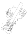
- FIG. 3 is a partially exploded perspective view of the connector according to the embodiment.
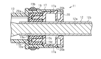
- FIG. 4 is a partial cross-sectional view of the connector in one embodiment.
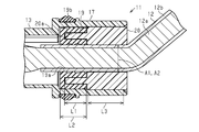
- FIG. 5 is a partial cross-sectional view of the connector according to the embodiment.
- FIG. 6 is a partial cross-sectional view of a connector using a thick electric wire member.
- the connectors of this disclosure are [1] A tubular rubber seal interposed between a housing having a tubular electric wire insertion portion in which a part of the electric wire member is inserted, and an inner surface of the electric wire insertion portion and an outer surface of the electric wire member.
- the connector is provided with a retainer that is interposed between the inner surface of the electric wire insertion portion and the outer surface of the electric wire member and is fixed to the electric wire insertion portion to prevent the rubber seal from coming off.
- An annular recess having a shape recessed from one end surface and surrounding the through hole of the rubber seal is formed, and the retainer is provided with a fitting insertion tube portion fitted into the annular recess.
- the rubber seal is recessed from one end surface to form an annular recess having a shape surrounding the through hole of the rubber seal, and the retainer is provided with an insertion tube portion fitted into the annular recess.
- the thickness of the rubber seal can be optimally set inside and outside the retaining tube portion of the retainer, both the assembling property and the waterproof property can be improved. Further, the housing having the same configuration can be used as a common part even when the electric wire member is thick. That is, when a thick electric wire member is adopted, the distance between the electric wire insertion portion and the electric wire member becomes small, and even if the rubber seal is provided in the entire gap, the rubber seal does not become thick, so that both the assembling property and the waterproof property should be good. Is possible.
- the length of the retainer in contact with the electric wire insertion portion is preferably set to be equal to or larger than the inner diameter of the retainer.
- the length of the retainer in contact with the electric wire insertion portion is set to be equal to or larger than the inner diameter of the retainer, that is, the diameter of the electric wire member passing through the retainer, so that the electric wire member is outside the electric wire insertion portion. It is possible to receive the bending force mainly by the retainer and make it difficult to transmit it to the rubber seal. Therefore, the deformation of the rubber seal can be suppressed, and the waterproof property between the electric wire member and the rubber seal can be improved.
- the depth of the annular recess is preferably set to half or more of the length of the rubber seal.
- the thickness of the rubber seal inside and outside the fitting cylinder portion is set within the range of half or more of the length of the rubber seal.
- Each can be set.
- the assembling property and the waterproof property are both improved as compared with the case where the thickness of the rubber seal inside and outside the fitting and inserting tube portion is set within the range of less than half of the length of the rubber seal. Can be done.
- the connector 11 is fitted in the height direction to a mating connector 10 provided in an electric device such as an inverter (not shown) mounted on a vehicle, for example. Further, the connector 11 is for electrically connecting and holding the electric wire member 12 held by the connector 11 to the terminal of the mating connector 10.
- the connector 11 includes a housing 13, a first cover 14 provided so as to cover the outer surface of the housing 13, and a second cover 15.
- the housing 13 is made of a resin material.
- the first and second covers 14 and 15 are made of a metal material and function as an electromagnetic shield.
- the housing 13 includes a main body portion 16 and an electric wire insertion portion 17 extending from the main body portion 16 in a direction orthogonal to the height direction.
- the electric wire insertion portion 17 is formed in a tubular shape and is opened in a direction orthogonal to the height direction so that the tip end portion of the electric wire member 12 is inserted.
- the electric wire insertion portions 17 of the present embodiment have a cylindrical shape, and a pair of electric wire insertion portions 17 are provided side by side at the same height in parallel.
- a lower housing 18 fitted with the mating connector 10 is fixed below the main body 16 of the housing 13 in the height direction.
- the electric wire member 12 has a core wire 12a such as a conductive metal wire and an insulating coating 12b that covers the outer periphery of the core wire 12a (see FIGS. 4 and 5).
- a female terminal 12c that is electrically connected to the terminal of the mating connector 10 is fixed to the tip of the core wire 12a exposed from the insulating coating 12b.
- the connector 11 includes a rubber seal 19 and a retainer 20.
- the rubber seal 19 is formed in a tubular shape and is interposed between the inner surface of the electric wire insertion portion 17 and the outer surface of the electric wire member 12.
- the retainer 20 is formed in a tubular shape and is fixed to the electric wire insertion portion 17 while being interposed between the inner surface of the electric wire insertion portion 17 and the outer surface of the electric wire member 12, and restricts the rubber seal 19 from coming off from the electric wire insertion portion 17. To do.
- the rubber seal 19 is formed with an annular recess 19b that is recessed from one end surface of the rubber seal 19 and surrounds the through hole 19a of the rubber seal 19. Further, the retainer 20 is provided with a fitting / inserting cylinder portion 20a to be fitted into the annular recess 19b.
- the rubber seal 19 is formed in a tubular shape having a through hole 19a in the center thereof, and an annular recess 19b surrounding the through hole 19a is formed on one end surface of the through hole 19a in the penetrating direction.
- the depth L1 of the annular recess 19b is set to be more than half of the length L2 of the rubber seal 19 and 3/4 or more of the length L2 of the rubber seal 19 in the present embodiment.
- the retainer 20 is a combination of a pair of retainer members 21 divided by 180 degrees.
- the length L3 in contact with the electric wire insertion portion 17 of the retainer 20 is set to the inner diameter A1 or more of the retainer 20, in other words, the diameter A2 or more of the electric wire member 12 passing through the retainer 20.
- the electric wire member 12 of the present embodiment has a diameter A2 of 18 mm.
- the retainer 20 is formed with a shape corresponding to the annular recess 19b and fitted into the annular recess 19b with almost no gap, and a fitting and inserting cylinder portion 20a to be fitted into the annular recess 19b is formed.
- the fitting / inserting cylinder portion 20a is formed by being divided into a pair of retainer members 21. Further, as shown in FIGS. 3 and 4, the retainer 20 is formed with a locking projection 20b that is elastically deformable in the radial direction and projects outward in the radial direction. The locking projections 20b are formed for each retainer member 21, and the retainer 20 in which the pair of retainer members 21 are combined is provided with the pair of locking projections 20b at 180 degree intervals.
- the retainer 20 is inserted into the electric wire insertion portion 17, the retainer 20 is fixed to the electric wire insertion portion 17 by fitting the locking projection 20b into the locking hole 17a formed in the electric wire insertion portion 17 and locking the retainer 20.
- FIG. 4 is a cross-sectional view of a portion corresponding to the locking projection 20b
- FIG. 5 is a sectional view of a portion where the locking projection 20b is not provided.
- the rubber seal 19 and the retainer 20 are assembled to the electric wire member 12, and the tip end side of the electric wire member 12 is inserted into the electric wire insertion portion 17.
- the rubber seal 19 is press-fitted into the electric wire insertion portion 17, and the retainer 20 is locked into the electric wire insertion portion 17 by fitting the locking projection 20b into the locking hole 17a. It is fixed.
- the lower housing 18 is assembled below the main body 16 of the housing 13. Further, the main body 16 of the housing 13 is covered with the first cover 14 from above, the electric wire insertion portion 17 of the housing 13 is covered with the second cover 15, and the second cover 15 is fixed to the first cover 14 with screws 22. ..
- the connector 11 assembled as described above is a screw that is fitted from above into a mating connector 10 provided in an electric device such as an inverter, penetrates the first cover 14, and is screwed into the electric device. It will be fixed to the electric device at 23.
- the head of the screw 23 is covered with the cap 24.
- the connector 11 of the present embodiment is configured to be assembled by being fitted to the mating connector 10 from above, but the present invention is not limited to this, and all assembly methods such as a straight fitting method and a bolt fastening method are used. It may be changed to the one having the above configuration.
- the rubber seal 19 is recessed from one end surface to form an annular recess 19b having a shape surrounding the through hole 19a of the rubber seal 19, and the retainer 20 is provided with an insertion tube portion 20a fitted into the annular recess 19b. .. Therefore, even when the distance between the electric wire insertion portion 17 and the electric wire member 12 is large, the waterproofness between the electric wire member 12 and the rubber seal 19 is improved while the assembling property of the rubber seal 19 to the electric wire insertion portion 17 is good. be able to.
- the rubber seal 19 can be optimally set inside and outside the fitting / inserting tube portion 20a of the retainer 20, both the assembling property and the waterproof property are made good. Can be done. Further, the housing 13 of the present embodiment can be used as a common part even when the electric wire member 12 is thick. That is, as shown in FIG.
- the length L3 in contact with the electric wire insertion portion 17 of the retainer 20 is set to be equal to or larger than the inner diameter A1 of the retainer 20, that is, the diameter A2 or more of the electric wire member 12 passing through the retainer 20, as shown in FIG.
- the force when the electric wire member 12 is bent outside the electric wire insertion portion 17 is mainly received by the retainer 20 and can be made difficult to be transmitted to the rubber seal 19. Therefore, the deformation of the rubber seal 19 can be suppressed, and the waterproof property between the electric wire member 12 and the rubber seal 19 can be improved.
- the depth L1 of the annular recess 19b is set to be half or more of the length L2 of the rubber seal 19, the rubber seal 19 inside and outside the fitting tube portion 20a is set within the range of half or more of the length L2 of the rubber seal 19.
- the thickness can be set individually. In this way, both the assembling property and the waterproof property are better than the case where the thickness of the rubber seal 19 inside and outside the fitting insertion tube portion 20a is set within the range of less than half the length of the rubber seal 19. Can be.
- the depth L1 of the annular recess 19b is set to 3/4 or more of the length L2 of the rubber seal 19, so that both the assembling property and the waterproof property can be further improved. It becomes.
- the rubber seal 19 includes an elastic inner cylinder 19c for partitioning the through hole 19a, an elastic outer cylinder 19d provided on the radial outer side of the elastic inner cylinder 19c, an elastic inner cylinder 19c, and an elastic outer cylinder 19d.
- An annular gap defined between the elastic inner cylinder 19c and the elastic outer cylinder 19d of the rubber seal 19 constitutes an annular recess 19b.
- the annular recess 19b facilitates the elastic deformation of the rubber seal 19, and thus facilitates the work of assembling the rubber seal 19 to the wire insertion portion 17.
- the thickness of the elastic inner cylinder 19c, the thickness of the elastic outer cylinder 19d, and the radial dimension of the annular wall 19e can be set independently.
- the radial dimensions of the elastic inner cylinder 19c, the elastic outer cylinder 19d, and the annular wall 19e are independently set according to the outer diameter of the electric wire member 12 and / or the inner diameter of the electric wire insertion portion 17 of the housing 13. can do.
- the electric wire insertion portion 17 of the housing 13 can have a stopper surface or a step 17b that faces or contacts the annular wall 19e of the rubber seal 19 in the axial direction.
- the step 17b prevents a liquid such as rubber seal 19 water from entering the depth of the housing 13 beyond the step 17b.
- the elastic inner cylinder 19c and the elastic outer cylinder 19d of the rubber seal 19 may be in close contact with the entire circumference of the fitting / inserting cylinder portion 20a of the retainer 20.
- the outer peripheral surface and the inner peripheral surface of the fitting insertion tube portion 20a of the retainer 20 may be smooth surfaces, and the outer peripheral surface of the elastic inner cylinder 19c and the inner peripheral surface of the elastic outer cylinder 19d of the rubber seal 19 are smooth surfaces. It may be.
- This configuration is advantageous for continuously surface-contacting the rubber seal 19 and the retainer 20 with an axial length. In one example, the work of inserting the retainer 20 into the rubber seal 19 is facilitated.
- the work of separately attaching the rubber seal 19 and the retainer 20 to the electric wire insertion portion 17 is facilitated. For example, it becomes easy to insert a part or the whole of the rubber seal 19 into the electric wire insertion portion 17, and then insert the fitting insertion tube portion 20a of the retainer 20 into the annular recess 19b of the rubber seal 19.
- This embodiment can be modified and implemented as follows.
- the present embodiment and the following modified examples can be implemented in combination with each other within a technically consistent range.
- the length L3 in contact with the electric wire insertion portion 17 of the retainer 20 is set to the inner diameter A1 or more of the retainer 20, that is, the diameter A2 or more of the electric wire member 12 passing through the retainer 20.
- the inner diameter of the retainer 20 is not limited to A1, that is, the diameter of the electric wire member 12 may be set to less than A2.
- the depth L1 of the annular recess 19b is set to 3/4 or more of the length L2 of the rubber seal 19, but the depth L1 is not limited to this and is half or more of the length L2 of the rubber seal 19. It may be set to less than 3/4 of the length L2 of the rubber seal 19, or may be set to less than half of the length L2 of the rubber seal 19.
- the electric wire insertion portion 17 has a cylindrical shape, but the present invention is not limited to this, and may be another tubular shape such as a square tubular shape. In this case, it is preferable that the outer shape of the rubber seal 19 also corresponds to the shape of the electric wire insertion portion.
- the annular recess 19b and the fitting / inserting cylinder portion 20a are circular, but the present invention is not limited to this, and may be another annular shape such as a quadrangle.
- the retainer 20 is formed by combining a pair of retainer members 21 divided by 180 degrees, but the present invention is not limited to this, and may be, for example, a single member or three or more. It may be made by combining the members of.
- the rubber seal 19 is formed in a tubular shape with a single member, but the present invention is not limited to this, and for example, two or more members may be combined.
- the retainer 20 is fixed to the electric wire insertion portion 17 by being locked by fitting the locking projection 20b into the locking hole 17a of the electric wire insertion portion 17, but the present invention is limited to this. Instead, it may be fixed to the electric wire insertion portion 17 with a configuration other than the locking projection 20b.
- the connector 11 of the above embodiment includes a pair of electric wire insertion portions 17, but the connector 11 is not limited to this, and the connector 11 may include, for example, only one electric wire insertion portion 17, or three or more electric wires.
- the insertion portion 17 may be provided.
- the electric wire insertion portion 17 of the housing 13 of the embodiment is an example of a tubular electric wire lead-out port.
- the rubber seal 19 of the embodiment is an example of an elastic seal plug.
- the retainer 20 of the embodiment is an example of a plug retainer configured to prevent the elastic seal plug from falling off from the tubular electric wire lead-out port.
- the fitting / inserting tube portion 20a of the embodiment is an example of a tubular protrusion of the retainer 20.
- the electric wire insertion portion 17 of the housing 13 of the embodiment is an example of a tubular electric wire lead-out port.
- the rubber seal 19 of the embodiment is an example of an elastic seal plug.
- the retainer 20 of the embodiment is an example of a plug retainer configured to prevent the elastic seal plug from falling off from the tubular electric wire lead-out port.
- the fitting / inserting tube portion 20a of the embodiment is an example of a tubular protrusion of the retainer 20.
- the connector (11) is A connector housing (13) having a tubular wire lead-out port (17) and A wire (12) led out from the tubular wire lead-out port (17) to the outside of the connector housing (13), Attached to the tubular electric wire lead-out port (17) from the opening of the tubular electric wire lead-out port (17), between the inner surface of the tubular electric wire lead-out port (17) and the outer surface of the electric wire (12).
- Elastic seal plug (19) placed in The elastic seal plug (19) is attached to the tubular electric wire lead-out port (17) from the opening of the tubular electric wire lead-out port (17), and the elastic seal plug (19) is removed from the tubular electric wire lead-out port (17).
- the elastic seal plug (19) has an elastic inner cylinder (19c) configured to be in watertight contact with the outer surface of the electric wire (12) and the inner surface of the tubular electric wire outlet port (17). It may have an elastic outer cylinder (19d) configured to be in contact with the elastic inner cylinder (19d) and an annular groove (19b) partitioned by the elastic inner cylinder (19c) and the elastic outer cylinder (19d).
- the plug retainer (20) can have a tubular protrusion (20a) that is inserted into the annular groove (19b) of the elastic seal plug (19).
- the tubular protrusion (20a) of the plug retainer (20) presses the elastic inner cylinder (19c) of the elastic seal plug (19) in the radial direction toward the outer surface of the electric wire (12). May be configured, The tubular protrusion (20a) of the plug retainer (20) radially directs the elastic outer cylinder (19d) of the elastic seal plug (19) toward the inner surface of the tubular wire lead-out port (17). It may be configured to press against.
- the elastic seal plug (19) is attached separately from the plug retainer (20), or the elastic seal plug (19) is attached to the plug retainer (20). In the state, it may be configured so as to be attached to the tubular electric wire lead-out port (17).
- the tubular protrusion (20a) of the retainer (20) may be configured to make axial slide contact with the annular groove (19b) of the elastic seal plug (19).
- the connector (11) may be provided at one end of a vehicle wire harness.
Landscapes
- Connector Housings Or Holding Contact Members (AREA)
Abstract
本開示は、組み付け性と防水性とが共に良好なコネクタを提供する。コネクタ11は、電線部材12の一部が挿入された状態とされる筒状の電線挿入部17を有するハウジング13と、電線挿入部17の内面と電線部材12の外面との間に介在される筒状のゴムシール19と、電線挿入部17の内面と電線部材12の外面との間に介在されつつ電線挿入部17に固定されてゴムシール19の抜けを規制するリテーナ20とを備える。ゴムシール19には、一端面から凹設され自身の貫通孔19aを囲う形状の環状凹部19bが形成され、リテーナ20には、環状凹部19bに嵌挿された嵌挿筒部20aが設けられる。
Description
本開示は、コネクタに関するものである。
従来、コネクタとしては、電線部材の一部が挿入された状態とされる筒状の電線挿入部を有するハウジングを備えたものがある(例えば、特許文献1参照)。このコネクタは、電線挿入部の内面と電線部材の外面との間に介在される筒状のゴムシールと、電線挿入部の開口部に装着されてゴムシールの抜けを規制するリテーナとを備え、外部に露出した電線部材を伝ってコネクタの内部に液体が浸入することが防止される。
ところで、上記したようなコネクタは、電線挿入部と電線部材との間隔が大きくなる場合がある。具体的には、例えば、品番が同じハウジングを共通部品として太い電線部材に対応させつつ細い電線部材にも対応させる場合等では、細い電線部材を採用した際に電線挿入部と電線部材との間隔が大きくなるといったことがある。このような場合では、電線挿入部と電線部材との隙間全体に設けられるゴムシールの厚さが厚くなるため、電線部材とゴムシールとの間の防水性を良好としながら、ゴムシールの電線挿入部への組み付け性を良好とすることが難しかった。すなわち、太い電線部材を採用した際のゴムシールの圧縮率と同等の圧縮率のゴムシールとしようとすると、ゴムシールの外径が大きくなりすぎてゴムシールを電線挿入部へ挿入する際の組み付け性が悪くなるといったことがあった。
本発明は、上記課題を解決するためになされたものであって、その目的は、組み付け性と防水性とが共に良好なコネクタを提供することにある。
本開示のコネクタは、電線部材の一部が挿入された状態とされる筒状の電線挿入部を有するハウジングと、前記電線挿入部の内面と前記電線部材の外面との間に介在される筒状のゴムシールと、前記電線挿入部の内面と前記電線部材の外面との間に介在されつつ前記電線挿入部に固定されて前記ゴムシールの抜けを規制するリテーナとを備えたコネクタであって、前記ゴムシールには、一端面から凹設され前記ゴムシールの貫通孔を囲う形状の環状凹部が形成され、前記リテーナには、前記環状凹部に嵌挿された嵌挿筒部が設けられる。
本開示のコネクタによれば、組み付け性と防水性とを共に良好とすることができる。
[本開示の実施形態の説明]
最初に本開示の実施態様を列記して説明する。
最初に本開示の実施態様を列記して説明する。
本開示のコネクタは、
[1]電線部材の一部が挿入された状態とされる筒状の電線挿入部を有するハウジングと、前記電線挿入部の内面と前記電線部材の外面との間に介在される筒状のゴムシールと、前記電線挿入部の内面と前記電線部材の外面との間に介在されつつ前記電線挿入部に固定されて前記ゴムシールの抜けを規制するリテーナとを備えたコネクタであって、前記ゴムシールには、一端面から凹設され前記ゴムシールの貫通孔を囲う形状の環状凹部が形成され、前記リテーナには、前記環状凹部に嵌挿された嵌挿筒部が設けられる。
[1]電線部材の一部が挿入された状態とされる筒状の電線挿入部を有するハウジングと、前記電線挿入部の内面と前記電線部材の外面との間に介在される筒状のゴムシールと、前記電線挿入部の内面と前記電線部材の外面との間に介在されつつ前記電線挿入部に固定されて前記ゴムシールの抜けを規制するリテーナとを備えたコネクタであって、前記ゴムシールには、一端面から凹設され前記ゴムシールの貫通孔を囲う形状の環状凹部が形成され、前記リテーナには、前記環状凹部に嵌挿された嵌挿筒部が設けられる。
同構成によれば、ゴムシールには一端面から凹設され前記ゴムシールの貫通孔を囲う形状の環状凹部が形成され、リテーナには環状凹部に嵌挿された嵌挿筒部が設けられるため、電線挿入部と電線部材との間隔が大きい場合でも、ゴムシールの電線挿入部への組み付け性を良好としながら、電線部材とゴムシールとの間の防水性を良好とすることができる。すなわち、電線挿入部と電線部材との間隔が大きい場合にその隙間全体に一様にゴムシールを設けた場合では、ゴムシールが厚くなり前記組み付け性と前記防水性とを共に良好とすることは難しいが、リテーナの嵌挿筒部の内外でゴムシールの厚さをそれぞれ最適に設定できることから、前記組み付け性と前記防水性とを共に良好とすることができる。また、同構成のハウジングは、電線部材が太い場合にも共通部品として使用することが可能となる。すなわち、太い電線部材を採用する場合は電線挿入部と電線部材との間隔が小さくなりその隙間全体にゴムシールを設けてもゴムシールが厚くならないので前記組み付け性と前記防水性とを共に良好とすることが可能となる。
[2]前記リテーナの前記電線挿入部に接する長さは、前記リテーナの内径以上に設定されることが好ましい。
同構成によれば、前記リテーナの前記電線挿入部に接する長さは、前記リテーナの内径以上、すなわち、リテーナを通る電線部材の直径以上に設定されるため、電線挿入部の外部で電線部材が曲げられた際の力を主にリテーナで受け止めてゴムシールに伝わりにくくすることができる。よって、ゴムシールの変形を抑えることができ、電線部材とゴムシールとの間の防水性を良好とすることができる。
[3]前記環状凹部の深さは、前記ゴムシールの長さの半分以上に設定されることが好ましい。
同構成によれば、前記環状凹部の深さは、前記ゴムシールの長さの半分以上に設定されるため、ゴムシールの長さの半分以上の範囲で嵌挿筒部の内外のゴムシールの厚さをそれぞれ設定することができる。このようにすると、ゴムシールの長さの半分未満の範囲で嵌挿筒部の内外のゴムシールの厚さをそれぞれ設定した場合に比べて、前記組み付け性と前記防水性とを共により良好とすることができる。
[本開示の実施形態の詳細]
本開示のコネクタの具体例を、以下に図面を参照しつつ説明する。なお、本発明はこれらの例示に限定されるものではなく、特許請求の範囲によって示され、特許請求の範囲と均等の意味および範囲内でのすべての変更が含まれることが意図される。
本開示のコネクタの具体例を、以下に図面を参照しつつ説明する。なお、本発明はこれらの例示に限定されるものではなく、特許請求の範囲によって示され、特許請求の範囲と均等の意味および範囲内でのすべての変更が含まれることが意図される。
図1に示すように、コネクタ11は、例えば車両に搭載される図示しないインバータ等の電気機器に設けられた相手側コネクタ10と高さ方向に嵌着されるものである。また、コネクタ11は、コネクタ11に保持された電線部材12を相手側コネクタ10の端子に電気的に接続して保持するためのものである。
図2に示すように、コネクタ11は、ハウジング13と、該ハウジング13の外表面を覆うように設けられる第1カバー14と、第2カバー15とを備える。ハウジング13は、樹脂材料よりなる。第1及び第2カバー14,15は、金属材料よりなり、電磁シールドとして機能する。
ハウジング13は、本体部16と、該本体部16から高さ方向の直交方向に延びる電線挿入部17とを備える。電線挿入部17は、筒状に形成され、高さ方向の直交方向に開口し電線部材12の先端部が挿入された状態とされる。本実施形態の電線挿入部17は、円筒状であり、同じ高さに一対が平行に並んで設けられている。ハウジング13の本体部16における高さ方向の下方には、前記相手側コネクタ10と嵌着される下部ハウジング18が固定される。電線部材12は、導電性金属線などの芯線12aと該芯線12aの外周を被覆する絶縁被覆12bとを有する(図4及び図5参照)。絶縁被覆12bから露出した芯線12aの先端部には、前記相手側コネクタ10の端子と電気的に接続されるメス端子12cが固定されている。
図3~図5に示すように、コネクタ11は、ゴムシール19とリテーナ20とを備える。ゴムシール19は、筒状に形成され、電線挿入部17の内面と電線部材12の外面との間に介在される。リテーナ20は、筒状に形成され、電線挿入部17の内面と電線部材12の外面との間に介在されつつ電線挿入部17に固定されて、ゴムシール19の電線挿入部17からの抜けを規制する。
そして、ゴムシール19には、ゴムシール19の一端面から凹設されゴムシール19の貫通孔19aを囲う形状の環状凹部19bが形成されている。また、リテーナ20には、環状凹部19bに嵌挿される嵌挿筒部20aが設けられている。
詳しくは、ゴムシール19は、その中心に貫通孔19aを有する筒状に形成され、貫通孔19aの貫通方向の一端面には該貫通孔19aを囲う環状の環状凹部19bが形成されている。図5に示すように、環状凹部19bの深さL1は、ゴムシール19の長さL2の半分以上であって、本実施形態ではゴムシール19の長さL2の3/4以上に設定されている。
図3に示すように、リテーナ20は、180度ずつに分割された一対のリテーナ部材21が組み合わされてなる。図5に示すように、リテーナ20の電線挿入部17に接する長さL3は、リテーナ20の内径A1以上、言い換えると、リテーナ20を通る電線部材12の直径A2以上に設定されている。なお、本実施形態の電線部材12は、直径A2が18mmのものが採用されている。そして、リテーナ20には、環状凹部19bと対応した形状であって環状凹部19bに略隙間無く嵌まる形状に形成され、環状凹部19bに嵌挿される嵌挿筒部20aが形成されている。嵌挿筒部20aは、一対のリテーナ部材21に分割されて形成されている。また、リテーナ20には、図3及び図4に示すように、径方向に弾性変形可能で径方向外側に突出した係止突起20bが形成されている。係止突起20bは、リテーナ部材21毎に形成され、一対のリテーナ部材21が組み合わされたリテーナ20には、180度間隔で一対の係止突起20bが設けられている。そして、リテーナ20は、電線挿入部17に挿入されると、電線挿入部17に形成された係止孔17aに係止突起20bが嵌まって係止されることで電線挿入部17に固定される。なお、図4は、係止突起20bと対応した部位の断面図であり、図5は、係止突起20bが設けられていない部位の断面図である。
次に、上記のように構成されたコネクタ11及び電線部材12の組み付け手順及びその作用について説明する。
図2に示すように、まず電線部材12にゴムシール19及びリテーナ20を組み付けた状態として、その電線部材12の先端側を電線挿入部17に挿入する。このとき、図4に示すように、ゴムシール19は、電線挿入部17に圧入され、リテーナ20は、係止突起20bが係止孔17aに嵌まって係止されることで電線挿入部17に固定される。
そして、ハウジング13の本体部16における下方に下部ハウジング18を組み付ける。また、ハウジング13の本体部16に第1カバー14を上方から被せ、ハウジング13の電線挿入部17に第2カバー15を被せ、該第2カバー15を第1カバー14にネジ22にて固定する。
そして、上記のように組み付けられたコネクタ11は、例えばインバータ等の電気機器に設けられた相手側コネクタ10に上方から嵌着され、第1カバー14を貫通して電気機器に螺合されるネジ23にて該電気機器に固定されることになる。なお、ネジ23の頭部にはキャップ24が被せられる。また、本実施形態のコネクタ11は、相手側コネクタ10に上方から嵌着されて組み立てられる構成のものとしたが、これに限定されず、ストレート嵌合方式やボルト締結方式等、すべての組み立て方式の構成のものに変更してもよい。
次に、上記実施形態の効果を以下に記載する。
(1)ゴムシール19には一端面から凹設されゴムシール19の貫通孔19aを囲う形状の環状凹部19bが形成され、リテーナ20には環状凹部19bに嵌挿された嵌挿筒部20aが設けられる。よって、電線挿入部17と電線部材12との間隔が大きい場合でも、ゴムシール19の電線挿入部17への組み付け性を良好としながら、電線部材12とゴムシール19との間の防水性を良好とすることができる。すなわち、電線挿入部17と電線部材12との間隔が大きい場合にその隙間全体に環状凹部19bを有していないゴムシールを設けた場合では、ゴムシールが厚くなり前記組み付け性と前記防水性とを共に良好とすることは難しい。これに対して、本実施形態の構成では、リテーナ20の嵌挿筒部20aの内外でゴムシール19の厚さをそれぞれ最適に設定できることから、前記組み付け性と前記防水性とを共に良好とすることができる。また、本実施形態のハウジング13は、電線部材12が太い場合にも共通部品として使用することが可能となる。すなわち、図6に示すように、太い電線部材31を採用する場合は電線挿入部17と電線部材31との間隔が小さくなりその隙間全体にゴムシール32を設け嵌挿筒部20aを有していないリテーナ33としてもゴムシール32が厚くならないので前記組み付け性と前記防水性とを共に良好とすることが可能となる。言い換えると、ハウジング13は、品番が同じハウジング13を共通部品として太い電線部材31に対応させつつ細い電線部材12にも対応させる場合であっても、前記組み付け性と前記防水性とを共に良好とすることができる。
(2)リテーナ20の電線挿入部17に接する長さL3は、リテーナ20の内径A1以上、すなわち、リテーナ20を通る電線部材12の直径A2以上に設定されるため、図5に示すように、電線挿入部17の外部で電線部材12が曲げられた際の力を主にリテーナ20で受け止めてゴムシール19に伝わりにくくすることができる。よって、ゴムシール19の変形を抑えることができ、電線部材12とゴムシール19との間の防水性を良好とすることができる。
(3)環状凹部19bの深さL1は、ゴムシール19の長さL2の半分以上に設定されるため、ゴムシール19の長さL2の半分以上の範囲で嵌挿筒部20aの内外のゴムシール19の厚さをそれぞれ設定することができる。このようにすると、ゴムシール19の長さの半分未満の範囲で嵌挿筒部20aの内外のゴムシール19の厚さをそれぞれ設定した場合に比べて、前記組み付け性と前記防水性とを共により良好とすることができる。なお、本実施形態では、環状凹部19bの深さL1は、ゴムシール19の長さL2の3/4以上に設定されるため、前記組み付け性と前記防水性とを共に更に良好とすることが可能となる。
図4に示すように、ゴムシール19は、貫通孔19aを区画する弾性内側筒19cと、弾性内側筒19cの径方向外側に設けられた弾性外側筒19dと、弾性内側筒19cと弾性外側筒19dとを径方向に接続する底壁または環状壁19eとを有することができる。ゴムシール19の弾性内側筒19cと弾性外側筒19dとの間に区画される環状隙間が環状凹部19bを構成する。この環状凹部19bはゴムシール19が弾性変形するのを容易にし、したがって、ゴムシール19を電線挿入部17へ組付ける作業を容易にする。また、弾性内側筒19cの厚さと弾性外側筒19dの厚さと環状壁19eの径方向寸法を独立に設定するできる。例えば、電線部材12の外径に応じて及び/又はハウジング13の電線挿入部17の内径に応じて、弾性内側筒19c、弾性外側筒19d、及び環状壁19eの径方向寸法を独立して設定することができる。
図4に示すように、ハウジング13の電線挿入部17は、ゴムシール19の環状壁19eと軸方向に対面または接触するストッパ面または段差17bを有することができる。この段差17bは、ゴムシール19水などの液体が段差17bを越えてハウジング13の奥方に進入するのを抑制する。
ゴムシール19の弾性内側筒19c及び弾性外側筒19dと、リテーナ20の嵌挿筒部20aの全周と密着してよい。限定ではないが、リテーナ20の嵌挿筒部20aの外周面及び内周面は平滑面であってよく、ゴムシール19の弾性内側筒19cの外周面及び弾性外側筒19dの内周面は平滑面であってよい。この構成は、ゴムシール19とリテーナ20とを軸方向長さをもって連続的に面接触させるのに有利である。ある例では、ゴムシール19にリテーナ20を挿入する作業を容易にする。またある異例では、電線挿入部17にゴムシール19とリテーナ20とを別々に取り付ける作業を容易にする。例えば、ゴムシール19の一部または全体を電線挿入部17に挿入し、その後に、リテーナ20の嵌挿筒部20aをゴムシール19の環状凹部19bに挿入する作業が容易になる。
本実施形態は、以下のように変更して実施することができる。本実施形態及び以下の変更例は、技術的に矛盾しない範囲で互いに組み合わせて実施することができる。
・上記実施形態では、リテーナ20の電線挿入部17に接する長さL3は、リテーナ20の内径A1以上、すなわち、リテーナ20を通る電線部材12の直径A2以上に設定されるとしたが、これに限定されず、リテーナ20の内径A1未満、すなわち、電線部材12の直径A2未満に設定してもよい。
・上記実施形態では、環状凹部19bの深さL1は、ゴムシール19の長さL2の3/4以上に設定されるとしたが、これに限定されず、ゴムシール19の長さL2の半分以上でゴムシール19の長さL2の3/4未満に設定してもよいし、ゴムシール19の長さL2の半分未満に設定してもよい。
・上記実施形態では、電線挿入部17は、円筒状であるとしたが、これに限定されず、例えば、四角筒状等の他の筒状としてもよい。なお、この場合、ゴムシール19の外形も電線挿入部の形状に対応させることが好ましい。
・上記実施形態では、環状凹部19b及び嵌挿筒部20aを円形としたが、これに限定されず、例えば、四角形等の他の環状としてもよい。
・上記実施形態では、リテーナ20は、180度ずつに分割された一対のリテーナ部材21が組み合わされてなるとしたが、これに限定されず、例えば、単一の部材としてもよいし、3つ以上の部材を組み合わせてなるものとしてもよい。
・上記実施形態では、ゴムシール19は、単一の部材で筒状に形成されるとしたが、これに限定されず、例えば、2つ以上の部材を組み合わせてなるものとしてもよい。
・上記実施形態では、リテーナ20は、電線挿入部17の係止孔17aに係止突起20bが嵌まって係止されることで電線挿入部17に固定されるとしたが、これに限定されず、係止突起20b以外の構成で電線挿入部17に固定されるものとしてもよい。
・上記実施形態のコネクタ11は、電線挿入部17を一対備えるるが、これに限定されず、コネクタ11は、例えば、電線挿入部17を1つのみ備えてもよいし、3つ以上の電線挿入部17を備えてもよい。
実施形態のハウジング13の電線挿入部17は、筒状の電線導出ポートの一例である。実施形態のゴムシール19は、弾性シールプラグの一例である。実施形態のリテーナ20は、筒状の電線導出ポートからの弾性シールプラグの脱落を防止するように構成されるプラグリテーナの一例である。実施形態の嵌挿筒部20aは、リテーナ20の筒状突起の一例である。
本開示は、以下の実装例を包含する。限定のためでなく、理解の補助として例示的な実施形態のいくつかの構成要素の参照符号を付した。以下の実装例において記述した事項のうちの一部を省略してもよく、実装例において記述した事項のうちのいくつかを選択または抽出して組合せてもよい。
実施形態のハウジング13の電線挿入部17は、筒状の電線導出ポートの一例である。実施形態のゴムシール19は、弾性シールプラグの一例である。実施形態のリテーナ20は、筒状の電線導出ポートからの弾性シールプラグの脱落を防止するように構成されるプラグリテーナの一例である。実施形態の嵌挿筒部20aは、リテーナ20の筒状突起の一例である。
本開示は、以下の実装例を包含する。限定のためでなく、理解の補助として例示的な実施形態のいくつかの構成要素の参照符号を付した。以下の実装例において記述した事項のうちの一部を省略してもよく、実装例において記述した事項のうちのいくつかを選択または抽出して組合せてもよい。
[付記1]本開示の一又は複数の実装例に従うコネクタ(11)は、
筒状の電線導出ポート(17)を有するコネクタハウジング(13)と、
前記筒状の電線導出ポート(17)から前記コネクタハウジング(13)の外部に導出される電線(12)と、
前記筒状の電線導出ポート(17)の開口から前記筒状の電線導出ポート(17)に取り付けられ、前記筒状の電線導出ポート(17)の内面と前記電線(12)の外面との間に配置される弾性シールプラグ(19)と、
前記筒状の電線導出ポート(17)の前記開口から前記筒状の電線導出ポート(17)に取り付けられ、前記筒状の電線導出ポート(17)からの前記弾性シールプラグ(19)の脱落を防止するように構成されたプラグリテーナ(20)とを備えることができ、
前記弾性シールプラグ(19)は、前記電線(12)の前記外面に止水的に接触するように構成される弾性内側筒(19c)と、前記筒状の電線導出ポート(17)の前記内面に止水的に接触するように構成される弾性外側筒(19d)と、前記弾性内側筒(19c)と前記弾性外側筒(19d)とによって区画される環状溝(19b)とを有することができ、
前記プラグリテーナ(20)は、前記弾性シールプラグ(19)の前記環状溝(19b)に挿入される筒状突起(20a)を有することができる。
筒状の電線導出ポート(17)を有するコネクタハウジング(13)と、
前記筒状の電線導出ポート(17)から前記コネクタハウジング(13)の外部に導出される電線(12)と、
前記筒状の電線導出ポート(17)の開口から前記筒状の電線導出ポート(17)に取り付けられ、前記筒状の電線導出ポート(17)の内面と前記電線(12)の外面との間に配置される弾性シールプラグ(19)と、
前記筒状の電線導出ポート(17)の前記開口から前記筒状の電線導出ポート(17)に取り付けられ、前記筒状の電線導出ポート(17)からの前記弾性シールプラグ(19)の脱落を防止するように構成されたプラグリテーナ(20)とを備えることができ、
前記弾性シールプラグ(19)は、前記電線(12)の前記外面に止水的に接触するように構成される弾性内側筒(19c)と、前記筒状の電線導出ポート(17)の前記内面に止水的に接触するように構成される弾性外側筒(19d)と、前記弾性内側筒(19c)と前記弾性外側筒(19d)とによって区画される環状溝(19b)とを有することができ、
前記プラグリテーナ(20)は、前記弾性シールプラグ(19)の前記環状溝(19b)に挿入される筒状突起(20a)を有することができる。
[付記2]いくつかの実装例では、
前記プラグリテーナ(20)の前記筒状突起(20a)は、前記弾性シールプラグ(19)の前記弾性内側筒(19c)を前記電線(12)の前記外面に向けて径方向に押圧するように構成されてよく、
前記プラグリテーナ(20)の前記筒状突起(20a)は、前記弾性シールプラグ(19)の前記弾性外側筒(19d)を前記筒状の電線導出ポート(17)の前記内面に向けて径方向に押圧するように構成されてよい。
前記プラグリテーナ(20)の前記筒状突起(20a)は、前記弾性シールプラグ(19)の前記弾性内側筒(19c)を前記電線(12)の前記外面に向けて径方向に押圧するように構成されてよく、
前記プラグリテーナ(20)の前記筒状突起(20a)は、前記弾性シールプラグ(19)の前記弾性外側筒(19d)を前記筒状の電線導出ポート(17)の前記内面に向けて径方向に押圧するように構成されてよい。
[付記3]いくつかの実装例では、前記弾性シールプラグ(19)は前記プラグリテーナ(20)とは別々に、または、前記弾性シールプラグ(19)は前記プラグリテーナ(20)に取り付けられた状態で、前記筒状の電線導出ポート(17)に取り付け可能に構成されてよい。
[付記4]いくつかの実装例では、
前記弾性シールプラグ(19)が前記筒状の電線導出ポート(17)に取り付けられる前にまたは前記弾性シールプラグ(19)が前記筒状の電線導出ポート(17)に取り付けられた後に、前記プラグリテーナ(20)の前記筒状突起(20a)は、前記弾性シールプラグ(19)の前記環状溝(19b)に、軸方向にスライドコンタクトするように構成されてよい。
前記弾性シールプラグ(19)が前記筒状の電線導出ポート(17)に取り付けられる前にまたは前記弾性シールプラグ(19)が前記筒状の電線導出ポート(17)に取り付けられた後に、前記プラグリテーナ(20)の前記筒状突起(20a)は、前記弾性シールプラグ(19)の前記環状溝(19b)に、軸方向にスライドコンタクトするように構成されてよい。
[付記5]いくつかの実装例では、前記コネクタ(11)は、車両ワイヤハーネスの一端部に設けられてよい。
11 コネクタ
12 電線部材
12a 芯線
12b 絶縁被覆
12c メス端子
13 ハウジング
14 第1カバー
15 第2カバー
16 本体部
17 電線挿入部
17a 係止孔
18 下部ハウジング
19 ゴムシール
19a 貫通孔
19b 環状凹部
20 リテーナ
20a 嵌挿筒部
20b 係止突起
21 リテーナ部材
22,23 ネジ
24 キャップ
A1 内径
A2 直径
L1 深さ
L2,L3 長さ
12 電線部材
12a 芯線
12b 絶縁被覆
12c メス端子
13 ハウジング
14 第1カバー
15 第2カバー
16 本体部
17 電線挿入部
17a 係止孔
18 下部ハウジング
19 ゴムシール
19a 貫通孔
19b 環状凹部
20 リテーナ
20a 嵌挿筒部
20b 係止突起
21 リテーナ部材
22,23 ネジ
24 キャップ
A1 内径
A2 直径
L1 深さ
L2,L3 長さ
Claims (3)
- 電線部材の一部が挿入された状態とされる筒状の電線挿入部を有するハウジングと、
前記電線挿入部の内面と前記電線部材の外面との間に介在される筒状のゴムシールと、
前記電線挿入部の内面と前記電線部材の外面との間に介在されつつ前記電線挿入部に固定されて前記ゴムシールの抜けを規制するリテーナと
を備えたコネクタであって、
前記ゴムシールには、一端面から凹設され前記ゴムシールの貫通孔を囲う形状の環状凹部が形成され、
前記リテーナには、前記環状凹部に嵌挿された嵌挿筒部が設けられたコネクタ。 - 前記リテーナの前記電線挿入部に接する長さは、前記リテーナの内径以上に設定された請求項1に記載のコネクタ。
- 前記環状凹部の深さは、前記ゴムシールの長さの半分以上に設定された請求項1または請求項2に記載のコネクタ。
Priority Applications (3)
| Application Number | Priority Date | Filing Date | Title |
|---|---|---|---|
| DE112020002350.8T DE112020002350T5 (de) | 2019-05-13 | 2020-04-22 | Verbinder |
| CN202080031172.9A CN113748575B (zh) | 2019-05-13 | 2020-04-22 | 连接器 |
| US17/606,593 US20220239033A1 (en) | 2019-05-13 | 2020-04-22 | Connector |
Applications Claiming Priority (2)
| Application Number | Priority Date | Filing Date | Title |
|---|---|---|---|
| JP2019-090784 | 2019-05-13 | ||
| JP2019090784A JP7192652B2 (ja) | 2019-05-13 | 2019-05-13 | コネクタ |
Publications (1)
| Publication Number | Publication Date |
|---|---|
| WO2020230554A1 true WO2020230554A1 (ja) | 2020-11-19 |
Family
ID=73222895
Family Applications (1)
| Application Number | Title | Priority Date | Filing Date |
|---|---|---|---|
| PCT/JP2020/017279 Ceased WO2020230554A1 (ja) | 2019-05-13 | 2020-04-22 | コネクタ |
Country Status (5)
| Country | Link |
|---|---|
| US (1) | US20220239033A1 (ja) |
| JP (1) | JP7192652B2 (ja) |
| CN (1) | CN113748575B (ja) |
| DE (1) | DE112020002350T5 (ja) |
| WO (1) | WO2020230554A1 (ja) |
Families Citing this family (1)
| Publication number | Priority date | Publication date | Assignee | Title |
|---|---|---|---|---|
| JP7384880B2 (ja) * | 2021-10-19 | 2023-11-21 | 矢崎総業株式会社 | コネクタ |
Citations (3)
| Publication number | Priority date | Publication date | Assignee | Title |
|---|---|---|---|---|
| JPH056784A (ja) * | 1991-03-13 | 1993-01-14 | Fujikura Ltd | 防水コネクタ |
| JPH09147965A (ja) * | 1995-11-29 | 1997-06-06 | Yazaki Corp | 防水コネクタ |
| JP2016207481A (ja) * | 2015-04-23 | 2016-12-08 | 住友電装株式会社 | コネクタ |
Family Cites Families (10)
| Publication number | Priority date | Publication date | Assignee | Title |
|---|---|---|---|---|
| JPH043415Y2 (ja) * | 1986-03-12 | 1992-02-03 | ||
| DE50100570D1 (de) * | 2000-04-22 | 2003-10-09 | Spinner Gmbh Elektrotech | Steckverbinder für Koaxialkabel mit dünnwandigem Kabelaussenleiter |
| JP2007194028A (ja) * | 2006-01-18 | 2007-08-02 | Jst Mfg Co Ltd | 防水コネクタ |
| US7645154B2 (en) * | 2007-10-04 | 2010-01-12 | Ford Global Technologies, Llc | USB connector protective cover |
| CN101576187A (zh) * | 2008-05-08 | 2009-11-11 | Ti集团机车系统公司 | 快速连接器、松脱工具及其方法 |
| JP5772742B2 (ja) * | 2012-07-04 | 2015-09-02 | 日立金属株式会社 | 電線保持装置及びワイヤハーネス |
| JP2014154359A (ja) * | 2013-02-08 | 2014-08-25 | Yazaki Corp | コネクタ |
| US9577367B2 (en) * | 2014-04-09 | 2017-02-21 | Delphi Technologies, Inc. | Sealed connector with an extended seal sleeve and an anti-water pooling retainer |
| JP6439672B2 (ja) * | 2015-12-22 | 2018-12-19 | 株式会社オートネットワーク技術研究所 | ケーブルの保持構造 |
| JP6475677B2 (ja) | 2016-09-26 | 2019-02-27 | 矢崎総業株式会社 | シールドコネクタ |
-
2019
- 2019-05-13 JP JP2019090784A patent/JP7192652B2/ja active Active
-
2020
- 2020-04-22 DE DE112020002350.8T patent/DE112020002350T5/de active Pending
- 2020-04-22 CN CN202080031172.9A patent/CN113748575B/zh active Active
- 2020-04-22 WO PCT/JP2020/017279 patent/WO2020230554A1/ja not_active Ceased
- 2020-04-22 US US17/606,593 patent/US20220239033A1/en not_active Abandoned
Patent Citations (3)
| Publication number | Priority date | Publication date | Assignee | Title |
|---|---|---|---|---|
| JPH056784A (ja) * | 1991-03-13 | 1993-01-14 | Fujikura Ltd | 防水コネクタ |
| JPH09147965A (ja) * | 1995-11-29 | 1997-06-06 | Yazaki Corp | 防水コネクタ |
| JP2016207481A (ja) * | 2015-04-23 | 2016-12-08 | 住友電装株式会社 | コネクタ |
Also Published As
| Publication number | Publication date |
|---|---|
| CN113748575B (zh) | 2024-03-15 |
| JP2020187890A (ja) | 2020-11-19 |
| CN113748575A (zh) | 2021-12-03 |
| US20220239033A1 (en) | 2022-07-28 |
| JP7192652B2 (ja) | 2022-12-20 |
| DE112020002350T5 (de) | 2022-02-17 |
Similar Documents
| Publication | Publication Date | Title |
|---|---|---|
| JP5875136B2 (ja) | コネクタ | |
| US8827569B2 (en) | Connector | |
| US9059534B2 (en) | Shield connector | |
| JP5766979B2 (ja) | コネクタ | |
| KR101227312B1 (ko) | 커넥터 | |
| US20200321723A1 (en) | Connector | |
| JP7055783B2 (ja) | 嵌合コネクタ | |
| CN112134063B (zh) | 连接器 | |
| US20210091503A1 (en) | Connection terminal and terminal-equipped electric wire | |
| US20210057834A1 (en) | Connector | |
| JP7139072B2 (ja) | コネクタ接続構造体 | |
| CN104124556A (zh) | 具有弹性锁闩的电连接器 | |
| JP2018006012A (ja) | 同軸ケーブルコネクタ及びコネクタシステム | |
| WO2020230554A1 (ja) | コネクタ | |
| WO2014192517A1 (ja) | 防水コネクタ | |
| WO2022092078A1 (ja) | コネクタ | |
| JP2018006312A (ja) | 同軸ケーブルコネクタ及びコネクタシステム | |
| JP2014022062A (ja) | 防水コネクタ | |
| JP6262895B2 (ja) | コネクタ装置 | |
| JP6096599B2 (ja) | コネクタ装置 | |
| CN113764932A (zh) | 连接器 | |
| JP7792941B2 (ja) | 電気接続装置 | |
| CN218632505U (zh) | 具备具有4个端子的连接器部件的连接器 | |
| EP4183006B1 (en) | Connector | |
| JP2023102025A (ja) | 防水栓及びコネクタ |
Legal Events
| Date | Code | Title | Description |
|---|---|---|---|
| 121 | Ep: the epo has been informed by wipo that ep was designated in this application |
Ref document number: 20804427 Country of ref document: EP Kind code of ref document: A1 |
|
| 122 | Ep: pct application non-entry in european phase |
Ref document number: 20804427 Country of ref document: EP Kind code of ref document: A1 |