WO2020226006A1 - 空気入りタイヤ - Google Patents
空気入りタイヤ Download PDFInfo
- Publication number
- WO2020226006A1 WO2020226006A1 PCT/JP2020/014917 JP2020014917W WO2020226006A1 WO 2020226006 A1 WO2020226006 A1 WO 2020226006A1 JP 2020014917 W JP2020014917 W JP 2020014917W WO 2020226006 A1 WO2020226006 A1 WO 2020226006A1
- Authority
- WO
- WIPO (PCT)
- Prior art keywords
- circumferential direction
- center
- tire
- block
- groove
- Prior art date
- Legal status (The legal status is an assumption and is not a legal conclusion. Google has not performed a legal analysis and makes no representation as to the accuracy of the status listed.)
- Ceased
Links
Images







Classifications
-
- B—PERFORMING OPERATIONS; TRANSPORTING
- B60—VEHICLES IN GENERAL
- B60C—VEHICLE TYRES; TYRE INFLATION; TYRE CHANGING; CONNECTING VALVES TO INFLATABLE ELASTIC BODIES IN GENERAL; DEVICES OR ARRANGEMENTS RELATED TO TYRES
- B60C11/00—Tyre tread bands; Tread patterns; Anti-skid inserts
- B60C11/03—Tread patterns
-
- B—PERFORMING OPERATIONS; TRANSPORTING
- B60—VEHICLES IN GENERAL
- B60C—VEHICLE TYRES; TYRE INFLATION; TYRE CHANGING; CONNECTING VALVES TO INFLATABLE ELASTIC BODIES IN GENERAL; DEVICES OR ARRANGEMENTS RELATED TO TYRES
- B60C11/00—Tyre tread bands; Tread patterns; Anti-skid inserts
- B60C11/03—Tread patterns
- B60C11/12—Tread patterns characterised by the use of narrow slits or incisions, e.g. sipes
Definitions
- the present invention relates to a pneumatic tire.
- a plurality of grooves are formed on the surface of the tread portion for the purpose of discharging water between the tread tread surface and the road surface when traveling on a wet road surface, whereby the surface of the tread portion is so-called. It has a tread pattern. With conventional pneumatic tires, various performances are ensured by devising a tread pattern.
- the center main groove has a plurality of outer groove portions extending in the tire circumferential direction, a plurality of inner groove portions extending in the tire axial direction inside the outer groove portion in the tire circumferential direction, and an outer groove portion.
- the performance on snow is improved by forming a zigzag shape that includes a plurality of inclined portions that are inclined with respect to the tire circumferential direction and that connect the inner groove portion with the inner groove portion.
- the central block row is divided into adjacent block rows adjacent in the tire width direction by a dividing groove extending in the tire circumferential direction, and each adjacent block row is sequentially adjacent to the tire circumferential direction.
- a plurality of blocks are arranged, and a plurality of blocks on both sides of the dividing groove in the tire width direction are arranged so as to be offset from each other in the tire circumferential direction, and four sipes whose both ends are closed in each block are arranged in each block.
- both wear resistance and uneven wear resistance are achieved while ensuring ice and snow performance.
- the crown main groove provided between the shoulder main groove and the tire equator is located between the inclined portions inclined in opposite directions along the tire circumferential direction. It has an extending flute.
- the means for improving snow traction is to make the main groove extending in the tire circumferential direction zigzag.
- the main groove extends in the tire circumferential direction and swings in the tire width direction to form a convex portion protruding in the tire width direction in the block partitioned by the main groove.
- the edge component can be increased and the snow traction property can be improved by forming a convex portion protruding in the tire width direction in the block partitioned by the main groove. it can.
- the block is formed with a convex portion protruding in the tire width direction, the drainage property may be lowered, and the wet grip property which is the grip property on a wet road surface may be lowered. For this reason, it has been extremely difficult to secure snow traction while suppressing a decrease in wet grip.
- the present invention has been made in view of the above, and an object of the present invention is to provide a pneumatic tire capable of achieving both snow traction and wet grip.
- the pneumatic tire according to the present invention has the tire equatorial line in the tire width direction across the tire equatorial plane among a plurality of circumferential main grooves extending in the tire circumferential direction.
- the two inner circumferential main grooves which are the circumferential main grooves arranged on both sides of the surface, and the circumferential main groove arranged on the outer side of each of the two inner circumferential main grooves in the tire width direction.
- the outer circumferential main groove which is a groove, a plurality of center lug grooves arranged between the two inner circumferential main grooves and extending in the tire width direction, and the adjacent inner circumferential main groove and the outer circumference.
- a plurality of middle lug grooves arranged between the directional main grooves and extending in the tire width direction, a center block partitioned by the two inner circumferential main grooves and the center lug groove, and the adjacent inner circumference.
- a middle block defined by a directional main groove, the outer circumferential main groove, and the middle lug groove is provided, and the center block and the middle block have an edge portion defined by the inner circumferential main groove.
- the second circumferential direction portion extending in the tire circumferential direction and the position in the tire circumferential direction extend in the tire circumferential direction at a position different from the second circumferential direction portion, and the inner circumferential main groove with respect to the second circumferential direction portion.
- Convex area Sc defined by the direction portion, a virtual line extending the second circumferential direction portion toward the first circumferential direction portion in the middle block, and a convex portion partitioned by the first circumferential direction portion. It is characterized in that the part area Sm has a relationship of Sc> Sm.
- the center block is divided in the tire width direction by a center narrow groove.
- the center narrow groove extends linearly in the tire circumferential direction and the groove width is within the range of 1 mm or more and 5 mm or less.
- the center block has a length Lc1 in the tire circumferential direction of the first circumferential direction portion and a center small block arranged on both sides of the center narrow groove in the tire width direction in the tire circumferential direction.
- the relationship with the maximum length Lc is within the range of 0.2 ⁇ (Lc1 / Lc) ⁇ 0.4
- the middle block has the length Lm1 in the tire circumferential direction of the first circumferential direction portion and the said.
- the relationship with the maximum length Lm of the middle block in the tire circumferential direction is preferably in the range of 0.15 ⁇ (Lm1 / Lm) ⁇ 0.35.
- the center block is arranged on both sides of the center narrow groove in the tire width direction and the offset amount Dc in the tire width direction between the first circumferential direction portion and the second circumferential direction portion.
- the relationship between the center small block and the maximum width Wc in the tire width direction is within the range of 0.05 ⁇ (Dc / Wc) ⁇ 0.15
- the middle block is the first circumferential direction portion and the second peripheral portion.
- the relationship between the offset amount Dm with respect to the circumferential portion in the tire width direction and the maximum width Wm in the tire width direction of the middle block is within the range of 0.05 ⁇ (Dm / Wm) ⁇ 0.15. preferable.
- the center lug groove has two or more bent portions.
- the center block and the middle block are the offset amount Dc of the center block in the tire width direction between the first circumferential direction portion and the second circumferential direction portion, and the middle block.
- the relationship between the offset amount Dm of the first circumferential direction portion and the second circumferential direction portion in the tire width direction is within the range of 0.95 ⁇ (Dc / Dm) ⁇ 1.05, and the center block. It is preferable that the relationship between the length Lc1 of the first circumferential direction portion in the tire circumferential direction and the length Lm1 of the middle block in the tire circumferential direction of the first circumferential direction portion is Lc1> Lm1.
- the relationship between the center block having a length Lc1 in the tire circumferential direction of the first circumferential direction portion and a length Lc2 of the tire circumferential direction portion of the second circumferential direction portion is 0.
- the middle block has a length Lm1 in the tire circumferential direction of the first circumferential direction portion and a length of the tire circumferential direction of the second circumferential direction portion.
- the relationship with Lm2 is within the range of 0.5 ⁇ (Lm1 / Lm2) ⁇ 0.7.
- the center block has a width extending portion extending in the tire width direction at an intersection with the first circumferential direction portion at an edge portion partitioned by the center lug groove.
- the middle block has an inclined portion that is inclined with respect to the tire width direction and the tire circumferential direction at the intersection with the first circumferential direction portion at the edge portion partitioned by the middle lug groove.
- the center block and the middle block are the angle ⁇ c between the first circumferential direction portion and the width direction extending portion of the center block, and the angle between the first circumferential direction portion and the inclined portion of the middle block. It is preferable that ⁇ m has a relationship of ⁇ c ⁇ m.
- the relationship between the groove width Lwc of the center lug groove and the pitch Pc of the center blocks adjacent to each other in the tire circumferential direction via the center lug groove in the tire circumferential direction is 0.05. It is preferably in the range of ⁇ (Lwc / Pc) ⁇ 0.35.
- the pneumatic tire has a shoulder land portion located outside in the tire width direction of the outer circumferential main groove and partitioned by the outer circumferential main groove, and the maximum width of the center block in the tire width direction.
- the relationship between Wcw, the maximum width Wm in the tire width direction of the middle block, and the maximum width Wsw in the tire width direction of the shoulder land portion is within the range of 0.4 ⁇ (Wm / Wcw) ⁇ 0.6.
- it is preferable that the range is 0.8 ⁇ (Wsw / Wcw) ⁇ 1.0.
- the center block has small center blocks arranged on both sides of the center narrow groove in the tire width direction by being divided in the tire width direction by a center narrow groove extending in the tire circumferential direction.
- the shoulder land portion has small shoulder blocks arranged on both sides of the shoulder groove in the tire width direction by being divided in the tire width direction by a shoulder groove extending in the tire circumferential direction, and the center small. It is preferable that the same number of sipe is arranged in the block and the small shoulder block.
- the center block has small center blocks arranged on both sides of the center narrow groove in the tire width direction by being divided in the tire width direction by a center narrow groove extending in the tire circumferential direction.
- two open sipes are arranged in each of the center small block and the middle block, and one closed sipe is arranged between the open sipe and the center lug groove in the center small block. Therefore, it is preferable that one closed sipe is arranged between the open sipe and the middle lug groove in the middle block.
- the pneumatic tire according to the present invention has the effect of being able to achieve both snow traction and wet grip.
- FIG. 1 is a plan view showing a tread tread surface of a pneumatic tire according to an embodiment.
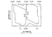
- FIG. 2 is a detailed view of the center block shown in FIG.
- FIG. 3 is a detailed view of part A of FIG.
- FIG. 4 is a detailed view of part B of FIG.
- FIG. 5 is a detailed view of part A of FIG. 1, and is an explanatory view of the dimensions of the convex portion of the center small block and the middle block.
- FIG. 6 is a detailed view of part A of FIG. 1, and is an explanatory view of the dimensions of the center small block and the middle block with respect to the lug groove.
- FIG. 7 is an explanatory diagram of the width of the land portion shown in FIG. FIG.
- FIG. 8 is a modified example of the pneumatic tire according to the embodiment, and is an explanatory view when the center groove oscillates.
- FIG. 9 is a modified example of the pneumatic tire according to the embodiment, and is an explanatory view when the center groove is curved.
- FIG. 10 is a modified example of the pneumatic tire according to the embodiment, and is an explanatory view when the center groove is formed in a crank shape.
- FIG. 11 is a modified example of the pneumatic tire according to the embodiment, and is an explanatory view when the center narrow groove is repeatedly bent.
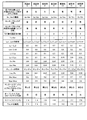
- FIG. 12A is a chart showing the results of the performance evaluation test of the pneumatic tire.
- FIG. 12B is a chart showing the results of the performance evaluation test of the pneumatic tire.
- FIG. 12C is a chart showing the results of the performance evaluation test of the pneumatic tire.
- the tire radial direction refers to a direction orthogonal to the rotation axis (not shown) of the pneumatic tire 1, and the tire radial inside means the side toward the rotation axis in the tire radial direction and the tire radial outside. Refers to the side away from the rotation axis in the tire radial direction.
- the tire circumferential direction refers to a circumferential direction centered on a rotation axis.
- the tire width direction means a direction parallel to the rotation axis, the inside in the tire width direction is the side toward the tire equatorial plane (tire equatorial line) CL in the tire width direction, and the outside in the tire width direction is in the tire width direction.
- the tire equatorial plane CL is a plane orthogonal to the rotation axis of the pneumatic tire 1 and passing through the center of the tire width of the pneumatic tire 1, and the tire equatorial plane CL is the center of the pneumatic tire 1 in the tire width direction.
- the position in the tire width direction coincides with the center line in the tire width direction.
- the tire width is the width of the outermost portions in the tire width direction in the tire width direction, that is, the distance between the portions farthest from the tire equatorial plane CL in the tire width direction.
- the tire equatorial line is a line on the tire equatorial plane CL along the tire circumferential direction of the pneumatic tire 1.
- FIG. 1 is a plan view showing the tread tread 3 of the pneumatic tire 1 according to the embodiment.
- a tread portion 2 is arranged on the outermost portion in the tire radial direction, and the surface of the tread portion 2, that is, a vehicle on which the pneumatic tire 1 is mounted (not shown).
- ) Is formed as a tread tread 3 at a portion that comes into contact with the road surface during traveling.
- a plurality of circumferential main grooves 30 extending in the tire circumferential direction and a plurality of lug grooves 40 extending in the tire width direction are formed on the tread tread 3.
- a plurality of land portions 10 are partitioned on the tread tread 3 by these plurality of circumferential main grooves 30 and lug grooves 40.
- main grooves 30 in the circumferential direction are formed side by side in the tire width direction, and two inner grooves are arranged on both sides of the tire equatorial plane CL in the tire width direction with the tire equatorial plane CL in between.
- the outer circumferential main groove 32 is the circumferential main groove 30 arranged on the outermost side in the tire width direction among the plurality of circumferential main grooves 30.
- the lug groove 40 includes a center lug groove 41 arranged between two inner circumferential main grooves 31 and extending in the tire width direction, and an inner circumferential main groove 31 adjacent to the tire width direction and an outer circumferential direction.
- a middle lug groove 42 arranged between the main groove 32 and extending in the tire width direction and a shoulder lug groove 43 arranged outside the outer peripheral direction main groove 32 in the tire width direction and extending in the tire width direction are provided. Has been done.
- the circumferential main groove 30 referred to here is a vertical groove having at least a part extending in the tire circumferential direction.
- the circumferential main groove 30 has a groove width of 4 mm or more, a groove depth of 10 mm or more, and has a tread wear indicator (slip sign) indicating the end of wear inside.
- the circumferential main groove 30 has a groove width of 5 mm or more and a groove depth of 15 mm or more, and the tire equatorial line (center) where the tire equatorial plane CL and the tread tread 3 intersect. Line) is substantially parallel.
- the inner circumferential main groove 31 is formed by repeatedly bending in the tire width direction while extending in the tire circumferential direction.
- the outer circumferential main groove 32 may extend linearly in the tire circumferential direction, or may be formed in a wavy shape or a zigzag shape. In the present embodiment, the outer circumferential main groove 32 is also formed by repeatedly bending in the tire width direction while extending in the tire circumferential direction, similarly to the inner circumferential main groove 31.
- the lug groove 40 has a groove width within a range of 4 mm or more and 10 mm or less, and a groove depth within a range of 7 mm or more and 15 mm or less.
- the lug groove 40 extends in the tire width direction and is inclined in the tire circumferential direction with respect to the tire width direction.
- the tread tread 3 is formed with a circumferential fine groove 50 extending in the tire circumferential direction with a groove width narrower than the groove width of the circumferential main groove 30 and the groove width of the lug groove 40.
- the circumferential narrow groove 50 is arranged outside the center narrow groove 51 arranged between the two inner peripheral main grooves 31 and the outer peripheral main groove 32 in the tire width direction.
- a shoulder narrow groove 52 is provided.
- the circumferential fine groove 50 referred to here has a groove width in the range of 1 mm or more and 5 mm or less, and a groove depth in the range of 7 mm or more and 20 mm or less.
- the center narrow groove 51 is arranged between the two inner peripheral main grooves 31 and substantially near the center in the tire width direction, and is located near the center of the tire equator. It is located on the surface CL or in the vicinity of the tire equatorial surface CL.
- the center narrow groove 51 formed in this way extends linearly in the tire circumferential direction, and both ends in the tire circumferential direction are opened in the center lug groove 41. That is, the center narrow groove 51 is formed so as to extend in the tire circumferential direction between the center lug grooves 41 adjacent to each other in the tire circumferential direction, and both ends are opened in the center lug groove 41, respectively.
- the center narrow groove 51 does not have to extend strictly in the tire circumferential direction, and may be slightly inclined with respect to the tire circumferential direction.
- the center groove 51 is preferably formed within ⁇ 2 ° with respect to the tire circumferential direction.
- the shoulder narrow groove 52 is arranged near the center in the tire width direction between the main groove 32 in the outer circumferential direction and the design end E which is the outer end of the tread tread 3 in the tire width direction.
- the design end E referred to here refers to the outermost end in the tire width direction of the tread portion 2, and is the outermost end in the tire width direction in which a groove is formed in the tread portion 2.
- the shoulder narrow groove 52 formed in this way extends in the tire circumferential direction and repeatedly bends in the tire width direction. That is, the shoulder groove 52 has a zigzag shape that extends in the tire circumferential direction and repeatedly bends in the tire width direction, and extends in the tire circumferential direction.
- a plurality of shoulder lug grooves 43 arranged on the outer side of the outer peripheral direction main groove 32 in the tire width direction are arranged on both sides of the shoulder narrow groove 52 in the tire width direction.
- the shoulder lug groove 43 arranged inside the shoulder narrow groove 52 in the tire width direction has an outer end on the inner side in the tire width direction. It opens in the main groove 32 in the circumferential direction, and the outer end in the tire width direction opens in the shoulder narrow groove 52.
- the shoulder lug groove 43 arranged on the outer side of the shoulder narrow groove 52 in the tire width direction is the inner end portion in the tire width direction. Is open in the shoulder groove 52, and the outer end in the tire width direction is opened at the design end E. That is, the shoulder lug grooves 43 arranged on both sides of the shoulder narrow groove 52 in the tire width direction have one end opened in the shoulder narrow groove 52 and the end portion of the shoulder lug groove 43 on the side that opens in the shoulder narrow groove 52. The ends on the opposite side of the shoulder lug grooves 43 are opened at different positions on both sides of the shoulder narrow groove 52 in the tire width direction. As described above, the shoulder lug groove 43 is provided with different shoulder lug grooves 43 on the inner side and the outer side of the shoulder narrow groove 52 in the tire width direction.
- a plurality of land portions 10 are formed on the tread tread 3 by a plurality of circumferential main grooves 30, a lug groove 40, and a circumferential fine groove 50, and the land portion 10 includes a center block 11 and a middle block 12. And a shoulder land portion 13.
- the center block 11 is located between the two inner circumferential main grooves 31, and is a land portion 10 partitioned by the two inner circumferential main grooves 31 and the center lug groove 41.
- the middle block 12 is located between the inner circumferential main groove 31 and the outer circumferential main groove 32 adjacent to each other in the tire width direction, and is adjacent to the inner circumferential main groove 31, the outer circumferential main groove 32, and the middle lug.
- the shoulder land portion 13 is located outside in the tire width direction of the outer circumferential main groove 32, and is a land portion 10 partitioned by the outer circumferential main groove 32 and the shoulder lug groove 43.
- the center lug groove 41, the middle lug groove 42, and the shoulder lug groove 43 that partition the land portion 10 as described above are all inclined in the tire circumferential direction with respect to the tire width direction.
- the center block 11 is divided in the tire width direction by the center narrow groove 51, and two centers arranged on both sides of the center narrow groove 51 in the tire width direction.
- Each has a small block 11a.
- each center small block 11a is partitioned by center lug grooves 41 on both sides in the tire circumferential direction, the outer side in the tire width direction is partitioned by the inner peripheral main groove 31, and the inner side in the tire width direction is the center narrow groove 51. It is partitioned by.
- the center block 11 forms a center narrow groove in a center small block row 21 in which a plurality of center small blocks 11a partitioned by the center lug groove 41, the inner circumferential main groove 31 and the center narrow groove 51 are arranged in the tire circumferential direction. It has 51 on both sides in the tire width direction.
- a plurality of center small blocks 11a are arranged on both sides of the center narrow groove 51 in the tire width direction, and in the center block 11, a plurality of center small blocks 11a are tires on both sides of the center narrow groove 51 in the tire width direction.
- the center narrow groove 51 has center small block rows 21 on both sides in the tire width direction.
- both ends of the center lug groove 41 for partitioning the center small block 11a are open to the inner circumferential main groove 31, the center lug groove 41 is the center small on both sides of the center narrow groove 51 in the tire width direction.
- the end of the small center block 11a in the block row 21 in the tire circumferential direction is partitioned by one center lug groove 41.
- the center lug groove 41 that partitions the ends of the two center small blocks 11a located on both sides of the center narrow groove 51 in the tire circumferential direction at the same position in the tire circumferential direction on the same side in the tire circumferential direction is It is continuously formed from one center small block 11a side to the other center small block 11a side.
- a plurality of middle blocks 12 are arranged between the center block 11 and the shoulder land portion 13, both sides in the tire circumferential direction are partitioned by middle lug grooves 42, and the inner side in the tire width direction is mainly in the inner circumferential direction. It is partitioned by a groove 31, and the outer side in the tire width direction is partitioned by a main groove 32 in the outer circumferential direction.
- a plurality of the middle blocks 12 formed in this way are arranged in the tire circumferential direction, and between the center block 11 and the shoulder land portion 13, the middle block rows 22 are formed by the plurality of middle blocks 12 arranged in the tire circumferential direction. Is formed.
- the shoulder land portion 13 is divided in the tire width direction by the shoulder narrow groove 52, and the shoulder small groove 52 is divided on both sides in the tire width direction and both sides in the tire circumferential direction by the shoulder lug groove 43.
- Each of the blocks 13a has a plurality of blocks 13a.
- the shoulder small block 13a located inside the shoulder narrow groove 52 in the tire width direction is partitioned by shoulder lug grooves 43 on both sides in the tire circumferential direction, and is partitioned by the outer circumferential main groove 32 in the tire width direction.
- the outside in the tire width direction is partitioned by the shoulder groove 52.
- the shoulder small block 13a located on the outer side of the shoulder narrow groove 52 in the tire width direction is partitioned by shoulder lug grooves 43 on both sides in the tire circumferential direction, and the inner side in the tire width direction is partitioned by the shoulder narrow groove 52, and the tire width.
- the outside in the direction is partitioned by the design end E.
- the shoulder land portion 13 has shoulder small block rows 23 in which a plurality of shoulder small blocks 13a partitioned in this way are arranged in the tire circumferential direction, respectively, on both sides of the shoulder narrow groove 52 in the tire width direction.
- a plurality of small shoulder blocks 13a are arranged on both sides of the shoulder narrow groove 52 in the tire width direction, and a plurality of shoulder small blocks 13a are arranged on both sides of the shoulder narrow groove 52 in the tire width direction.
- the shoulder narrow grooves 52 have shoulder small block rows 23 on both sides in the tire width direction.
- different shoulder lug grooves 43 are arranged on both sides of the shoulder narrow groove 52 in the tire width direction. Therefore, the shoulder lug groove 43 divides the end portions of the shoulder small block 13a in the shoulder small block rows 23 on both sides of the shoulder narrow groove 52 in the tire width direction in the tire circumferential direction by different shoulder lug grooves 43.
- a plurality of sipes 70 are formed on each land portion 10 formed on the tread tread 3. That is, a plurality of sipes 70 are formed in the center small block 11a, the middle block 12, and the shoulder small block 13a, respectively.
- the sipe 70 referred to here is formed in a fine groove shape on the tread tread 3, and the pneumatic tire 1 is rim-assembled on a regular rim to form a fine groove under normal internal pressure internal pressure conditions when no load is applied.
- the wall surfaces do not come into contact with each other, but when a fine groove is located on the ground contact surface formed on the flat plate when the load is applied in the vertical direction on the flat plate, or when the land part where the fine groove is formed collapses. It means that the wall surfaces constituting the narrow groove, or at least a part of the portion provided on the wall surface, come into contact with each other due to the deformation of the land portion 10.
- the regular rim is a "standard rim” specified by JATTA, a "Design Rim” specified by TRA, or a “Measuring Rim” specified by ETRTO.
- the normal internal pressure is the "maximum air pressure” specified by JATTA, the maximum value described in "TIRE LOAD LIMITS AT VARIOUS COLD INFLATION PRESSURES" specified by TRA, or "INFLATION PRESSURES" specified by ETRTO.
- the sipe 70 has a width of less than 1 mm and a depth of 7 mm or more and 12 mm or less.
- the sipes 70 formed as described above have the same number of sipes 70 in the center small block 11a, the middle block 12, and the shoulder small block 13a, respectively. Have been placed. Further, the sipe 70 includes an open sipe 71 whose end in the tire width direction opens in the circumferential main groove 30 or the circumferential narrow groove 50, and a closed sipe 72 whose end in the tire width direction terminates in the land portion 10. have. Further, these sipes 70 are formed by repeatedly bending in the tire circumferential direction while extending in the tire width direction substantially parallel to the extending direction of the lug groove 40 for partitioning the land portion 10 on which the sipes 70 are formed. ing.
- two open sipes 71 are arranged in each of the center small block 11a and the middle block 12. Further, in the center small block 11a, one closed sipe 72 is arranged between the open sipe 71 and the center lug groove 41, and in the middle block 12, the closed sipe 72 is arranged between the open sipe 71 and the middle lug groove 42. Is arranged. That is, in the center small block 11a, two open sipes 71 are arranged in the tire circumferential direction, and one closed sipe 72 is arranged between each open sipe 71 and the center lug groove 41. .. Similarly, in the middle block 12, two open sipe 71s are arranged in the tire circumferential direction, and one closed sipe 72 is arranged between each open sipe 71 and the middle lug groove 42.
- the shoulder small block 13a four closed sipes 72 are arranged side by side in the tire circumferential direction in each of the shoulder small blocks 13a located on both sides of the shoulder narrow groove 52 in the tire width direction. ..
- four closed sipes 72 are arranged in the shoulder small block 13a, and two open sipes 71 and two closed sipes 72 are arranged in the center small block 11a and the middle block 12, respectively, for a total of four.
- the book sipe 70 is arranged. Therefore, the same number of sipes 70 are arranged in the center small block 11a, the middle block 12, and the shoulder small block 13a, respectively.
- FIG. 2 is a detailed view of the center block 11 shown in FIG.
- the sipe 70 is omitted for convenience in order to explain the shape of the land portion 10.
- the center lug groove 41 arranged between the two inner circumferential main grooves 31 is open to the inner circumferential main grooves 31 having different ends in the tire width direction. Further, the center lug groove 41 is formed by bending in the tire circumferential direction at a plurality of points while extending in the tire width direction, that is, the center lug groove 41 has an angle in the tire circumferential direction with respect to the tire width direction. It has two or more bent portions 45, which are parts that change.
- the bent portions 45 are formed at two locations with respect to one center lug groove 41.
- the bending directions of the two bent portions 45 are opposite to each other when heading from one inner circumferential main groove 31 side to the other inner circumferential main groove 31 side along the center lug groove 41.
- the center lug groove 41 is formed in a crank-like shape.
- each of the portions extending from the two bent portions 45 toward the main groove 31 in the inner peripheral direction is inclined with respect to the tire width direction.
- the direction of inclination and the angle of inclination are two portions extending from the bent portion 45 toward the main groove 31 in the inner circumferential direction, and have the same direction and angle as each other.
- the plurality of center lug grooves 41 arranged between the two inner circumferential main grooves 31 are all formed in the same shape.
- the center narrow groove 51 whose end in the tire circumferential direction opens into the center lug groove 41 is open to the bent portion 45 of the center lug groove 41.
- the center lug groove 41 has two bent portions 45, and since the center narrow groove 51 is open to the bent portion 45 of the center lug groove 41, it is located on both sides of the center narrow groove 51 in the tire width direction.
- the center small blocks 11a are arranged so as to be offset from each other in the tire circumferential direction. That is, since the center lug groove 41 for partitioning the center small block 11a is formed in a crank shape, the positions of the bent portion 45 in the center lug groove 41 in the tire width direction are different on both sides in the tire circumferential direction. ..
- the center lug groove 41 is a tire on both sides of the bent portion 45 in the tire width direction.
- the positions in the circumferential direction are different, the positions of the center small blocks 11a located on both sides of the center narrow groove 51 in the tire width direction are also different in the tire circumferential direction as in the center lug groove 41.
- the center small blocks 11a located on both sides of the center narrow groove 51 in the tire width direction are arranged so as to be offset in the tire circumferential direction.
- FIG. 3 is a detailed view of part A of FIG.
- the positions of the center block 11 and the middle block 12 adjacent to each other via the main groove 31 in the inner circumferential direction are different in the tire circumferential direction. That is, the position where the center lug groove 41 for partitioning the center block 11 opens in the main groove 31 in the inner circumferential direction and the position where the middle lug groove 42 for partitioning the middle block 12 opens in the main groove 31 in the inner circumferential direction are the tire circumferences.
- the position in the direction is different. Therefore, for example, the center lug groove 41 is located between the positions where two middle lug grooves 42 adjacent to each other in the tire circumferential direction open to the inner circumferential main groove 31, with respect to the inner circumferential main groove 31. It is open.
- the middle lug groove 42 opens with respect to the inner circumferential main groove 31 at a position between the positions where two center lug grooves 41 adjacent to each other in the tire circumferential direction open into the inner circumferential main groove 31. ing.
- the center block 11 and the middle block 12 have an edge portion 60 partitioned by the inner peripheral direction main groove 31 because the inner peripheral direction main groove 31 extends in the tire circumferential direction and is repeatedly bent in the tire width direction.
- each is formed in a step shape.
- the center block 11 and the middle block 12 have an edge portion 60 partitioned by a main groove 31 in the inner circumferential direction, and has a first circumferential direction portion 61 and a second circumferential direction portion 62, respectively, extending in the tire circumferential direction. doing. That is, both the first circumferential direction portion 61 and the second circumferential direction portion 62 of the center block 11 and the middle block 12 are formed substantially parallel to the tire equatorial plane CL.
- first circumferential direction portion 61 and the second circumferential direction portion 62 do not have to extend strictly in the tire circumferential direction, and may be slightly inclined with respect to the tire circumferential direction.
- the first circumferential direction portion 61 and the second circumferential direction portion 62 are preferably formed within ⁇ 2 ° with respect to the tire circumferential direction.
- the position of the first circumferential direction portion 61 extends in the tire circumferential direction at a position different from that of the second circumferential direction portion 62, and the first circumferential direction portion 61 extends in the tire circumferential direction. It is offset toward the inner peripheral main groove 31 side with respect to the two circumferential direction portions 62. That is, the first circumferential direction portion 61 is closer to the center side of the groove width of the inner circumferential main groove 31 than the second circumferential direction portion 62, or the first circumferential direction portion 61 or the second in the inner circumferential main groove 31.
- the center block 11 having the first circumferential direction portion 61 and the second circumferential direction portion 62 and the edge portion 60 of the middle block 12 both extend in the tire circumferential direction and change their positions in the tire width direction. It is formed in a shape.
- the center block 11 has the edge portion 60 partitioned by the inner circumferential main groove 31 formed in a step shape, so that the portion partitioned by the inner circumferential main groove 31 is located outside in the tire width direction.
- a protruding convex portion 14 is formed. That is, the center block 11 projects outward in the tire width direction by offsetting the first circumferential direction portion 61 of the edge portion 60 partitioned by the inner circumferential main groove 31 with respect to the second circumferential direction portion 62.
- the convex portion 14 is formed, and the first circumferential direction portion 61 constitutes the edge portion 60 of the convex portion 14.
- the middle block 12 projects inward in the tire width direction to a portion defined by the inner peripheral direction main groove 31 by forming the edge portion 60 defined by the inner peripheral direction main groove 31 in a step shape.
- the convex portion 15 is formed. That is, the middle block 12 projects inward in the tire width direction by offsetting the first circumferential direction portion 61 of the edge portion 60 partitioned by the inner circumferential main groove 31 with respect to the second circumferential direction portion 62.
- the convex portion 15 is formed, and the first circumferential direction portion 61 constitutes the edge portion 60 of the convex portion 15.
- the direction portion 61 is arranged on the same side as the second circumferential direction portion 62 of the edge portion 60 of each block in the tire circumferential direction.
- the center lug groove 41 and the middle lug groove 42 are opened at different positions in the tire circumferential direction with respect to the inner circumferential main groove 31. Therefore, the positions of the first circumferential direction portion 61 of the edge portion 60 of the center block 11 and the first circumferential direction portion 61 of the edge portion 60 of the middle block 12 in the tire circumferential direction are different.
- the first circumferential direction portion 61 of the edge portion 60 of the center block 11 generally faces the second circumferential direction portion 62 of the edge portion 60 of the middle block 12, and the first edge portion 60 of the middle block 12
- the circumferential portion 61 generally faces the second circumferential portion 62 of the edge portion 60 of the center block 11. That is, the convex portion 14 of the center block 11 generally faces the second circumferential direction portion 62 of the edge portion 60 of the middle block 12, and the convex portion 15 of the middle block 12 generally faces the edge portion 60 of the center block 11. It faces the second circumferential direction portion 62.
- FIG. 4 is a detailed view of part B of FIG.
- a convex portion 14 is formed on the center block 11, and a convex portion 15 is formed on the middle block 12.
- the convex portion area Sc which is the area of the convex portion 14 of the center block 11, and the convex portion of the middle block 12
- the convex portion area Sm which is the area of the portion 15, has a relationship of Sc> Sm.
- the convex area Sc of the center block 11 includes a virtual line Vc in which the second circumferential direction portion 62 of the center block 11 is extended toward the first circumferential direction portion 61 in the tire circumferential direction and the first circumferential direction portion 61. It is an area partitioned by.
- the convex portion area Sc of the center block 11 is an area partitioned by the virtual line Vc extending the second circumferential direction portion 62 toward the convex portion 14 side and the convex portion 14.
- the convex area Sm of the middle block 12 is determined by the virtual line Vm in which the second circumferential direction portion 62 of the middle block 12 is extended toward the first circumferential direction portion 61 in the tire circumferential direction and the first circumferential direction portion 61. It is the area to be partitioned. That is, the convex portion area Sm of the middle block 12 is an area partitioned by the virtual line Vm extending the second circumferential direction portion 62 toward the convex portion 15 side and the convex portion 15.
- the relationship between the convex area Sc of the center block 11 and the convex area Sm of the middle block 12 is preferably within the range of 1.05 ⁇ (Sc / Sm) ⁇ 1.15.
- FIG. 5 is a detailed view of part A of FIG. 1, and is an explanatory view of dimensions of the center small block 11a and the convex portions 14 and 15 of the middle block 12.
- the center block 11 and the middle block 12 are the offset amount Dc between the first circumferential direction portion 61 and the second circumferential direction portion 62 of the edge portion 60 of the center block 11 in the tire width direction, and the edge portion 60 of the middle block 12.
- the relationship between the first circumferential direction portion 61 and the second circumferential direction portion 62 with the offset amount Dm in the tire width direction is within the range of 0.95 ⁇ (Dc / Dm) ⁇ 1.05.
- the offset amount Dc between the first circumferential direction portion 61 and the second circumferential direction portion 62 of the center block 11 and the offset amount Dm between the first circumferential direction portion 61 and the second circumferential direction portion 62 of the middle block 12 are , It is about the same size.
- the amount of protrusion of the convex portion 14 of the center small block 11a and the amount of protrusion of the convex portion 15 of the middle block 12 are about the same size.
- the relationship with is Lc1> Lm1.
- the relationship between the length Lc1 of the first peripheral direction portion 61 of the center block 11 in the tire circumferential direction and the length Lm1 of the first circumferential direction portion 61 of the middle block 12 in the tire circumferential direction is 1.1 ⁇ ( It is preferably within the range of Lc1 / Lm1) ⁇ 1.4.
- first circumferential direction portion 61 of the center block 11 and the middle block 12 is offset with respect to the second circumferential direction portion 62 of the center block 11 and the middle block 12, the first circumferential direction portion of each block Between the 61 and the second circumferential direction portion 62, there is a portion that is inclined with respect to the tire circumferential direction and connects the first circumferential direction portion 61 and the second circumferential direction portion 62, but is a center block.
- the length Lc1 of the first circumferential direction portion 61 of 11 and the length Lm1 of the first circumferential direction portion 61 of the middle block 12 are portions connecting the first circumferential direction portion 61 and the second circumferential direction portion 62 in this way. The length does not include.
- the relationship between the length Lc1 of the first circumferential direction portion 61 in the tire circumferential direction and the length Lc2 of the second circumferential direction portion 62 in the tire circumferential direction is 0.6 ⁇ (Lc1 / Lc2). ) ⁇ 0.8.
- the relationship between the length Lm1 of the first circumferential direction portion 61 in the tire circumferential direction and the length Lm2 of the second circumferential direction portion 62 in the tire circumferential direction is 0.5 ⁇ (Lm1 / Lm2). ) ⁇ 0.7.
- the relationship between the length Lc1 of the first circumferential direction portion 61 of the center block 11 and the length Lc2 of the second circumferential direction portion 62 is within the range of 0.65 ⁇ (Lc1 / Lc2) ⁇ 0.75.
- the relationship between the length Lm1 of the first circumferential direction portion 61 of the middle block 12 and the length Lm2 of the second circumferential direction portion 62 is within the range of 0.55 ⁇ (Lm1 / Lm2) ⁇ 0.65. Is preferable.
- the length Lc2 of the second circumferential direction portion 62 of the center block 11 and the length Lm2 of the second circumferential direction portion 62 of the middle block 12 are the length Lc1 of the first circumferential direction portion 61 of the center block 11.
- the length Lm1 of the first circumferential direction portion 61 of the middle block 12 does not include the portion connecting the first circumferential direction portion 61 and the second circumferential direction portion 62.
- the relationship between the length Lc1 of the first peripheral direction portion 61 in the tire circumferential direction and the maximum length Lc of the center small block 11a of the center block 11 in the tire circumferential direction is 0.2 ⁇ . It is within the range of (Lc1 / Lc) ⁇ 0.4.
- the relationship between the length Lm1 of the first circumferential direction portion 61 in the tire circumferential direction and the maximum length Lm of the middle block 12 in the tire circumferential direction is 0.15 ⁇ (Lm1 / Lm) ⁇ . It is within the range of 0.35.
- the relationship between the length Lc1 of the first circumferential direction portion 61 of the center block 11 and the maximum length Lc of the small center block 11a is within the range of 0.25 ⁇ (Lc1 / Lc) ⁇ 0.35.
- the relationship between the length Lm1 of the first circumferential direction portion 61 of the middle block 12 and the maximum length Lm of the middle block 12 is within the range of 0.2 ⁇ (Lm1 / Lm) ⁇ 0.3. Is preferable.
- the relationship between the offset amount Dc of the first circumferential direction portion 61 and the second circumferential direction portion 62 in the tire width direction and the maximum width Wc of the center small block 11a in the tire width direction is 0. It is within the range of 05 ⁇ (Dc / Wc) ⁇ 0.15.
- the relationship between the offset amount Dm between the first circumferential direction portion 61 and the second circumferential direction portion 62 in the tire width direction and the maximum width Wm in the tire width direction of the middle block 12 is 0.05. It is within the range of ⁇ (Dm / Wm) ⁇ 0.15.
- the relationship between the offset amount Dc between the first circumferential direction portion 61 and the second circumferential direction portion 62 of the center block 11 and the maximum width Wc of the small center block 11a is 0.08 ⁇ (Dc / Wc) ⁇ 0. It is preferably within the range of .12, and the relationship between the offset amount Dm between the first circumferential direction portion 61 and the second circumferential direction portion 62 of the middle block 12 and the maximum width Wm of the middle block 12 is 0. It is preferably in the range of .08 ⁇ (Dm / Wm) ⁇ 0.12.
- FIG. 6 is a detailed view of part A of FIG. 1, and is an explanatory view of the dimensions of the center small block 11a and the middle block 12 with respect to the lug groove 40.
- the center block 11 has a width direction extending portion 66 extending in the tire width direction at an intersection with the first circumferential direction portion 61 of the edge portion 60 partitioned by the center lug groove 41. That is, since the center lug groove 41 is formed so as to be inclined with respect to the tire width direction, the center lug groove 41 is formed in the tire width direction even at the edge portion 60 partitioned by the center lug groove 41 in the center block 11. On the other hand, the inclined portion is inclined in the tire circumferential direction with respect to the tire width direction.
- the direction of inclination of the center lug groove 41 is the edge portion 60 on both sides of the center lug groove 41 in the groove width direction, which is connected to the first circumferential direction portion 61, and the first circumferential direction portion 61.
- the portion closer to the first circumferential direction portion 61 is a width direction extending portion formed so as to extend in the tire width direction.
- the edge portion 60 of the center block 11 is partitioned by the center lug groove 41, and the widthwise extending portion 66 is connected to the first circumferential direction portion 61.
- the edge portion 60 defined by the center lug groove 41 in the center block 11 has a width direction extending portion 66 extending in the tire width direction at the intersection with the first circumferential direction portion 61 in this way.
- the middle block 12 has an inclined portion 67 inclined with respect to the tire width direction and the tire circumferential direction at the intersection with the first circumferential direction portion 61 in the edge portion 60 partitioned by the middle lug groove 42.
- the middle lug groove 42 extends in the tire width direction and is inclined in the tire circumferential direction with respect to the tire width direction, and the direction is among the edge portions 60 on both sides in the groove width direction of the middle lug groove 42.
- the relative angle between the edge portion 60 on the side connected to the first circumferential direction portion 61 and the first circumferential direction portion 61 is inclined in an acute angle direction.
- the edge portion 60 of the middle lug groove 42 on the side connected to the first circumferential direction portion 61 is bent at the portion closer to the first circumferential direction portion 61, and the bent portion and the first circumferential direction portion 61 are bent.
- the portion between the two is an inclined portion 67 that is inclined with respect to the tire width direction and the tire circumferential direction.
- the inclination direction of the inclined portion 67 in the tire circumferential direction with respect to the tire width direction is the portion other than the inclined portion 67 of the edge portion 60 of the middle lug groove 42 on the side connected to the first circumferential direction portion 61, with respect to the tire width direction. It is in the opposite direction of the inclination direction in the circumferential direction.
- the relative angle between the first circumferential direction portion 61 and the inclined portion 67 of the middle block 12 is an obtuse angle.
- the edge portion 60 defined by the middle lug groove 42 in the middle block 12 is inclined with respect to the tire width direction and the tire circumferential direction at the intersection with the first circumferential direction portion 61 in this way, and is the first circumferential direction portion. It has an inclined portion 67 whose relative angle with 61 is obtuse.
- the center block 11 having the extending portion 66 in the width direction and the middle block 12 having the inclined portion 67 are the angle ⁇ c between the first circumferential direction portion 61 of the center block 11 and the extending portion 66 in the width direction, and the middle block 12
- the angle ⁇ m between the first circumferential direction portion 61 and the inclined portion 67 is such that ⁇ c ⁇ m.
- the relationship between the angle ⁇ c between the first circumferential direction portion 61 of the center block 11 and the extending portion 66 in the width direction and the angle ⁇ m between the first circumferential direction portion 61 and the inclined portion 67 of the middle block 12 is 0. It is preferably in the range of 5 ⁇ ( ⁇ c / ⁇ m) ⁇ 0.8.
- the angle ⁇ c between the first circumferential direction portion 61 and the width direction extending portion 66 of the center block 11 is preferably in the range of 85 ° or more and 95 ° or less.
- the center lug groove 41 for partitioning the center block 11 and the center block 11 are the tire circumferences of the center blocks 11 adjacent to each other in the tire circumferential direction via the groove width Lwc of the center lug groove 41 and the center lug groove 41.
- the relationship with the pitch Pc in the direction is within the range of 0.05 ⁇ (Lwc / Pc) ⁇ 0.35.
- the groove width Lwc of the center lug groove 41 is the maximum width between the opposite groove walls of the center lug groove 41 in the portion of the center lug groove 41 other than the extending portion 66 in the width direction.
- the pitch Pc of the center blocks 11 adjacent to each other in the tire circumferential direction via the center lug groove 41 in the tire circumferential direction is, in other words, the center small blocks 11a adjacent to each other in the tire circumferential direction through the center lug groove 41.
- the pitch is Pc in the tire circumferential direction.
- the relationship between the groove width Lwc of the center lug groove 41 and the pitch Pc of the center block 11 in the tire circumferential direction is within the range of 0.15 ⁇ (Lwc / Pc) ⁇ 0.25.
- FIG. 7 is an explanatory diagram of the width of the land portion 10 shown in FIG. Regarding the center block 11 and the middle block 12, the relationship between the maximum width Wcw in the tire width direction of the center block 11 and the maximum width Wm in the tire width direction of the middle block 12 is 0.4 ⁇ (Wm / Wcw) ⁇ 0. It is within the range of 0.6. Further, in the center block 11 and the shoulder land portion 13, the relationship between the maximum width Wcw in the tire width direction of the center block 11 and the maximum width Wsw in the tire width direction of the shoulder land portion 13 is 0.8 ⁇ (Wsw /). It is within the range of Wcw) ⁇ 1.0.
- the middle block 12 and the shoulder land portion 13 are edge portions defined by the outer circumferential main groove 32 because the outer circumferential main groove 32 is repeatedly bent in the tire width direction while extending in the tire circumferential direction. 60 are each formed in a step shape.
- the middle block 12 is formed with a convex portion 16 projecting outward in the tire width direction at a portion partitioned by the outer circumferential main groove 32
- the shoulder land portion 13 is formed with an outer circumferential main groove.
- a convex portion 17 projecting inward in the tire width direction is formed in a portion partitioned by 32.
- the pneumatic tire 1 is used as a heavy-duty pneumatic tire.
- the pneumatic tire 1 is mounted on the vehicle, it is mounted on the vehicle in an inflated state by assembling the rim on the rim wheel.
- the pneumatic tire 1 in a state where the rim is assembled on the rim wheel is used by being mounted on a large vehicle such as a truck or a bus.
- the pneumatic tire 1 When a vehicle equipped with the pneumatic tire 1 runs, the pneumatic tire 1 rotates while the tread tread 3 located below the tread tread 3 is in contact with the road surface.
- the driving force and braking force are transmitted to the road surface and turning force is generated mainly by the frictional force between the tread tread surface 3 and the road surface. It runs by letting it run.
- water between the tread tread 3 and the road surface enters the circumferential main groove 30, the lug groove 40, etc., and the water between the tread tread 3 and the road surface in these grooves. Run while draining. This makes it easier for the tread tread 3 to come into contact with the road surface, and the frictional force between the tread tread 3 and the road surface allows the vehicle to travel.
- the pneumatic tire 1 when traveling on a snowy road surface, the pneumatic tire 1 compacts the snow on the road surface with the tread tread surface 3, and the snow on the road surface enters the circumferential main groove 30 and the lug groove 40, so that these snows are formed. Will be compacted in the groove.
- a driving force or a braking force acts on the pneumatic tire 1, or a force acts on the tire width direction due to the turning of the vehicle, so that the shearing force acts on the snow in the groove.
- a so-called snow column shearing force is generated between the pneumatic tire 1 and the snow.
- the shearing force of the snow column creates resistance between the pneumatic tire 1 and the road surface, so that the driving force and braking force can be transmitted to the road surface, resulting in snow traction. Since it can be secured, the vehicle can run on a snowy road surface.
- the circumferential main groove 30 is repeatedly bent in the tire width direction while extending in the tire circumferential direction, so that the portion of each land portion 10 partitioned by the circumferential main groove 30 is convex in the tire width direction. Parts 14, 15, 16 and 17 are formed. As a result, each land portion 10 can increase the edge component, and the snow traction property can be further improved.
- the edge portions 60 partitioned by the inner circumferential main grooves 31 of the center block 11 and the middle block 12 are formed in a step shape, respectively, so that the inner circumferential main grooves in the center block 11 and the middle block 12 are formed. Convex portions 14 and 15, respectively, are formed in the portions partitioned by 31. As a result, the center block 11 and the middle block 12 can increase the edge component and improve the snow traction property.
- the convex area Sc of the convex portion 14 of the center block 11 and the convex area Sm of the convex portion 15 of the middle block 12 have a relationship of Sc> Sm. It has become.
- the inner circumferential main groove 31 has a large convex area Sc, and the convex portion 14 of the center block 11 improves the snow traction property, while the convex portion 15 of the middle block 12 has a small convex area Sm. It is possible to suppress a decrease in drainage property in the inner peripheral direction main groove 31. Therefore, since the drainage property can be ensured when traveling on a wet road surface, the ground contact property of the tread tread 3 when traveling on a wet road surface can be ensured, and the wet property which is a grip property on a wet road surface can be ensured. Grip property can be ensured. As a result, both snow traction and wet grip can be achieved at the same time.
- the center block 11 is divided in the tire width direction by the center narrow groove 51, the drainage property can be ensured by the center fine groove 51.
- the drainage property when the edge portion 60 partitioned by the inner peripheral direction main groove 31 is formed in a step shape to secure the snow traction property can be ensured by the center narrow groove 51.
- both snow traction and wet grip can be more reliably achieved.
- center narrow groove 51 extends linearly in the tire circumferential direction and the groove width is within the range of 1 mm or more and 5 mm or less, water flows in the center fine groove 51 while suppressing a decrease in the rigidity of the center block 11. It can be made easier to flow. As a result, the drainage property of the center narrow groove 51 can be more reliably ensured. As a result, the wet grip property can be improved more reliably.
- the relationship between the length Lc1 of the first circumferential direction portion 61 of the center block 11 and the maximum length Lc of the center small block 11a is within the range of 0.2 ⁇ (Lc1 / Lc) ⁇ 0.4. Further, the relationship between the length Lm1 of the first circumferential direction portion 61 of the middle block 12 and the maximum length Lm of the middle block 12 is within the range of 0.15 ⁇ (Lm1 / Lm) ⁇ 0.35. Therefore, it is possible to more reliably achieve both snow traction and wet grip.
- the length Lc1 of the first circumferential direction portion 61 of the center block 11 or the middle block 12 may be too short.
- the volume of the convex portion 14 of the center block 11 and the convex portion 15 of the middle block 12 becomes small, and it becomes difficult to secure the rigidity of the convex portions 14 and 15, so that the grip when the center block 11 and the middle block 12 are in contact with the ground There is a risk that the property will easily deteriorate.
- the length Lc1 of the first circumferential direction portion 61 of the center block 11 or the middle block 12 may be too long. In this case, it may be difficult to secure the volume of the inner circumferential main groove 31, and the amount of snow and water that can enter the inner circumferential main groove 31 is reduced, so that snow traction and wet grip are obtained. May be difficult to secure effectively.
- the convex portion 14 of the center block 11 It is possible to secure the volume of the inner peripheral main groove 31 while suppressing the volume of the convex portion 15 of the middle block 12 from becoming too small. As a result, more snow and water can enter the main groove 31 in the inner circumferential direction while ensuring the rigidity of the convex portions 14 and 15 more reliably. As a result, both snow traction and wet grip can be more reliably achieved.
- the relationship between the offset amount Dc between the first circumferential direction portion 61 and the second circumferential direction portion 62 of the center block 11 and the maximum width Wc of the center small block 11a is 0.05 ⁇ (Dc / Wc) ⁇ 0.
- the relationship between the offset amount Dm between the first circumferential direction portion 61 and the second circumferential direction portion 62 of the middle block 12 and the maximum width Wm of the middle block 12 is 0.05 ⁇ (Dm). Since it is within the range of / Wm) ⁇ 0.15, it is possible to more reliably achieve both snow traction and wet grip.
- the first of the center block 11 While suppressing the offset amount Dc between the circumferential direction portion 61 and the second circumferential direction portion 62 and the offset amount Dm between the first circumferential direction portion 61 and the second circumferential direction portion 62 of the middle block 12 from becoming too small,
- the volume of the main groove 31 in the inner circumferential direction can be secured.
- more snow and water can enter the inner circumferential main groove 31 while effectively ensuring snow traction by the convex portions 14 and 15.
- both snow traction and wet grip can be more reliably achieved.
- the center lug groove 41 has two or more bent portions 45, the center small block 11a and the center lug groove 41 can secure a snow column shearing force in a plurality of directions. As a result, the snow traction property can be improved more reliably.
- the offset amount Dc between the first circumferential direction portion 61 and the second circumferential direction portion 62 of the center block 11 and the offset amount Dm between the first circumferential direction portion 61 and the second circumferential direction portion 62 of the middle block 12 Since the relationship is within the range of 0.95 ⁇ (Dc / Dm) ⁇ 1.05, it is possible to more reliably achieve both snow traction and wet grip. That is, when (Dc / Dm) ⁇ 0.95 or (Dc / Dm)> 1.05, the difference between the offset amount Dc of the center block 11 and the offset amount Dm of the middle block 12 is It may become too large.
- the offset amount between the first circumferential direction portion 61 and the second circumferential direction portion 62 is large, the flow of water flowing in the inner circumferential main groove 31 may be obstructed and the drainage property may be deteriorated. Further, on the side where the offset amount between the first circumferential direction portion 61 and the second circumferential direction portion 62 is small, even if the first circumferential direction portion 61 and the second circumferential direction portion 62 are offset, the snow traction property is effective. It may be difficult to secure it.
- the offset amount Dc of the center block 11 and the offset amount Dm of the middle block 12 are within the range of 0.95 ⁇ (Dc / Dm) ⁇ 1.05, the offset of the center block 11 Since the amount Dc and the offset amount Dm of the middle block 12 can be made about the same, it is possible to effectively secure the snow traction property while ensuring the ease of flow of water in the inner circumferential main groove 31. Can be done. As a result, both snow traction and wet grip can be more reliably achieved.
- the offset amount of the center block 11 The convex area Sc of the convex portion 14 of the center block 11 can be made larger than the convex area Sm of the convex portion 15 of the middle block 12 without increasing the Dc too much.
- the convex area Sc of the convex portion 14 of the center block 11 is increased while suppressing the deterioration of the drainage property of the main groove 31 in the inner circumferential direction when the convex area Sc of the convex portion 14 of the center block 11 is increased. This makes it possible to improve snow traction. As a result, both snow traction and wet grip can be more reliably achieved.
- the relationship between the length Lc1 of the first circumferential direction portion 61 of the center block 11 and the length Lc2 of the second circumferential direction portion 62 is within the range of 0.6 ⁇ (Lc1 / Lc2) ⁇ 0.8.
- the relationship between the length Lm1 of the first circumferential direction portion 61 of the middle block 12 and the length Lm2 of the second circumferential direction portion 62 is within the range of 0.5 ⁇ (Lm1 / Lm2) ⁇ 0.7. , It is possible to more reliably achieve both snow traction and wet grip.
- the length Lc1 of the first circumferential direction portion 61 of the center block 11 or the middle block 12 may be too short.
- the volume of the convex portion 14 of the center block 11 and the convex portion 15 of the middle block 12 becomes small, and it becomes difficult to secure the rigidity of the convex portions 14 and 15, so that the grip when the center block 11 and the middle block 12 are in contact with the ground There is a risk that the property will easily deteriorate.
- the length Lc1 of the first circumferential direction portion 61 of the center block 11 or the middle block 12 may be too long. In this case, it may be difficult to secure the volume of the inner circumferential main groove 31, and the amount of snow and water that can enter the inner circumferential main groove 31 is reduced, so that snow traction and wet grip are obtained. May be difficult to secure effectively.
- the convex portion 14 of the center block 11 when it is within the range of 0.6 ⁇ (Lc1 / Lc2) ⁇ 0.8 and within the range of 0.5 ⁇ (Lm1 / Lm2) ⁇ 0.7, the convex portion 14 of the center block 11
- the volume of the inner peripheral main groove 31 can be secured while suppressing the volume of the convex portion 15 of the middle block 12 from becoming too small.
- more snow and water can enter the main groove 31 in the inner circumferential direction while ensuring the rigidity of the convex portions 14 and 15 more reliably.
- both snow traction and wet grip can be more reliably achieved.
- the angle ⁇ c between the first circumferential direction portion 61 of the center block 11 and the extending portion 66 in the width direction and the angle ⁇ m between the first circumferential direction portion 61 and the inclined portion 67 of the middle block 12 are ⁇ c ⁇ m. Because of the relationship, the convex area Sc of the convex portion 14 of the center block 11 can be made larger than the convex area Sm of the convex portion 15 of the middle block 12 more reliably. As a result, it is possible to more reliably improve the snow traction property by the convex portion 14 of the center block 11 and suppress the deterioration of the drainage property at the position on the middle block 12 side in the inner peripheral direction main groove 31. As a result, it is possible to more reliably achieve both snow traction and wet grip.
- the groove width Lwc of the center lug groove 41 and the pitch Pc between the center blocks 11 in the tire circumferential direction is within the range of 0.05 ⁇ (Lwc / Pc) ⁇ 0.35, it is more reliable. It is possible to achieve both snow traction and wet grip. That is, when the relationship between the groove width Lwc of the center lug groove 41 and the pitch Pc of the center block 11 is (Lwc / Pc) ⁇ 0.05, the groove width Lwc of the center lug groove 41 may be too narrow. , There is a risk that it will be difficult to secure the volume of the center lug groove 41.
- the relationship between the maximum width Wcw of the center block 11 in the tire width direction and the maximum width Wm of the middle block 12 in the tire width direction is within the range of 0.4 ⁇ (Wm / Wcw) ⁇ 0.6. , It is possible to more reliably achieve both snow traction and wet grip. That is, when the relationship between the maximum width Wcw of the center block 11 and the maximum width Wm of the middle block 12 is (Wm / Wcw) ⁇ 0.4, the middle block 12 has a relationship with the maximum width Wcw of the center block 11. Since the maximum width Wm is too small, the total length of the middle lug groove 42 may be too short.
- the center block 11 has the maximum width Wm of the middle block 12. Since the maximum width Wcw is too small, the total length of the center lug groove 41 may be too short. In this case, it may be difficult to secure the snow column shearing force and drainage property in the center lug groove 41.
- the maximum width Wcw of the center block 11 and the maximum width Wm of the middle block 12 are within the range of 0.4 ⁇ (Wm / Wcw) ⁇ 0.6, the maximum width of the center block 11 is the highest.
- Both the large Wcw and the maximum width Wm of the middle block 12 can be made an appropriate width.
- both the center lug groove 41 and the middle lug groove 42 can secure an appropriate total length, and in any of the lug grooves 40, the snow column shearing force and the drainage property can be appropriately secured. As a result, both snow traction and wet grip can be more reliably achieved.
- the relationship between the maximum width Wcw in the tire width direction of the center block 11 and the maximum width Wsw in the tire width direction of the shoulder land portion 13 is within the range of 0.8 ⁇ (Wsw / Wcw) ⁇ 1.0. In that case, it is possible to more reliably achieve both snow traction and wet grip. That is, when the relationship between the maximum width Wcw of the center block 11 and the maximum width Wsw of the shoulder land portion 13 is (Wsw / Wcw) ⁇ 0.8, the shoulder land portion is relative to the maximum width Wcw of the center block 11. Since the maximum width Wsw of 13 is too small, the length of the shoulder lug groove 43 may become too short.
- the center block 11 When the relationship between the maximum width Wcw of the center block 11 and the maximum width Wsw of the shoulder land portion 13 is (Wsw / Wcw)> 1.0, the center block is relative to the maximum width Wsw of the shoulder land portion 13. Since the maximum width Wcw of 11 is too small, the total length of the center lug groove 41 may be too short. In this case, it may be difficult to secure the snow column shearing force and drainage property in the center lug groove 41.
- the center block 11 when the relationship between the maximum width Wcw of the center block 11 and the maximum width Wsw of the shoulder land portion 13 is within the range of 0.8 ⁇ (Wsw / Wcw) ⁇ 1.0, the center block 11 Both the maximum width Wcw and the maximum width Wsw of the shoulder land portion 13 can be set to an appropriate width. As a result, an appropriate length can be secured for both the center lug groove 41 and the shoulder lug groove 43, and the snow column shearing force and drainage property can be appropriately secured for any of the lug grooves 40. it can. As a result, both snow traction and wet grip can be more reliably achieved.
- the edge component can be increased, and the edge effect more reliably provides snow traction and wet grip. Can be improved. Further, since the same number of sipes 70 are arranged in the center small block 11a, the shoulder small block 13a, and the middle block 12, the edge effect can be uniformly obtained over the entire area in the tire width direction, and the snow The traction and wet grip can be further improved. As a result, the snow traction property and the wet grip property can be improved more reliably.
- two open sipe 71s are arranged in each of the center small block 11a and the middle block 12, and one closed sipe 72 is arranged between the open sipe 71 and the lug groove 40, respectively. It is possible to more reliably improve the snow traction property and the wet grip property while suppressing the occurrence of uneven wear of the small block 11a and the middle block 12. That is, when arranging the sipe 70 in the center small block 11a or the middle block 12, by arranging the closed sipe 72 at a position closer to the lug groove 40, the rigidity at a position near the lug groove 40 where the rigidity tends to decrease is reduced. The edge effect can be improved while suppressing as much as possible.
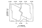
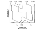
- the center narrow groove 51 is formed in a linear shape extending in the tire circumferential direction, but the center fine groove 51 may be formed in a shape other than the straight shape.
- FIG. 8 is a modified example of the pneumatic tire 1 according to the embodiment, and is an explanatory view when the center narrow groove 51 swings.
- FIG. 9 is a modified example of the pneumatic tire 1 according to the embodiment, and is an explanatory view when the center narrow groove 51 is curved.
- FIG. 10 is a modified example of the pneumatic tire 1 according to the embodiment, and is an explanatory view when the center narrow groove 51 is formed in a crank shape.
- FIG. 8 is a modified example of the pneumatic tire 1 according to the embodiment, and is an explanatory view when the center narrow groove 51 swings.
- FIG. 9 is a modified example of the pneumatic tire 1 according to the embodiment, and is an explanatory view when the center narrow groove 51 is curved.
- FIG. 10 is a modified example of the pneumatic tire 1 according to the embodiment,
- the center groove 51 may oscillate in the tire width direction while extending in the tire circumferential direction, for example. That is, the center narrow groove 51 may be formed in a zigzag shape while extending in the tire circumferential direction.
- the center groove 51 may oscillate in the tire width direction by repeating bending while extending in the tire circumferential direction, for example. That is, the center narrow groove 51 may be formed in a wavy shape while extending in the tire circumferential direction.
- the center narrow groove 51 extends in the tire width direction and bends at two points to form a crank shape between the center lug grooves 41 adjacent to each other in the tire circumferential direction. It may be formed by.
- the center narrow groove 51 is formed between both center lug grooves 41 while repeatedly bending between the center lug grooves 41 adjacent to each other in the tire circumferential direction, for example. You may.
- the center narrow groove 51 is formed in a shape capable of dividing the center block 11 in the tire width direction by being formed between the center lug grooves 41 that partition both sides of the center block 11 in the tire circumferential direction. If so, its shape does not matter.
- circumferential main grooves 30 are formed, but the circumferential main groove 30 may be other than four. Regardless of the number of the circumferential main grooves 30, the center block 11 and the middle block 12 are formed by the inner circumferential main groove 31 and the outer circumferential main groove 32 arranged on the outer side of the inner circumferential main groove 31 in the tire width direction. As long as and are partitioned, the number of circumferential main grooves 30 does not matter.
- two open sipes 71 and two closed sipes 72 are arranged in the center small block 11a and the middle block 12, and four closed sipes 72 are arranged in the shoulder small block 13a.
- the number and configuration of the sipes 70 formed in each land portion 10 may be other than this.
- the sipe 70 arranged on the land portion 10 is preferably set as appropriate according to the position and size of the land portion 10 on which the sipe 70 is arranged.
- Example 12A to 12C are charts showing the results of the performance evaluation test of the pneumatic tire.
- the performance evaluation test of the above-mentioned pneumatic tire 1 with respect to the pneumatic tire 1 according to the present invention and the pneumatic tire of the comparative example will be described.
- the snow traction property which is the traction performance on a snowy road surface
- the wet braking property which is a braking property on a wet road surface
- a tire with a nominal size of 275 / 80R22.5 specified by JATTA is assembled on the rim wheel of the specified rim specified by JATTA, and the air pressure is set to the maximum air pressure specified by JATTA.
- 2-D4 (2 wheels with 1 front axis-2 wheels with 2 rear axes, 4 wheels with front axis, drive axis, 4 wheels with rear axis, idle axis) mounted on a test vehicle (truck) for test driving I went by doing.
- the evaluation method for each test item is based on ECE R117-02 (ECE Evaluation No. 117 Evaluation 2) for snow traction, and the distance required for acceleration from the specified initial speed to the terminal speed on the snowy road surface. was measured to calculate the acceleration, and the calculated acceleration was evaluated by expressing it as an index with Comparative Example 1 described later as 100. The larger the value, the better the acceleration performance on the snowy road surface, and the higher the snow traction.
- the wet braking performance is performed in accordance with ECE R117-02, and the reciprocal of the braking distance from the specified initial speed to the stop on the sprinkled road surface is 100 in Comparative Example 1 described later. It was evaluated by expressing it as an index. The larger the value, the better the braking performance on a wet road surface, and the higher the wet braking performance.
- the edge portion 60 partitioned by the circumferential main groove 30 has a step shape, and the convex portion of the center block 11
- the convex area Sc of 14 and the convex area Sm of the convex portion 15 of the middle block 12 all satisfy the relationship of Sc> Sm. Further, in the pneumatic tire 1 according to Examples 1 to 19, whether or not the center block 11 is divided, whether or not the center block 11 is divided by the center narrow groove 51 extending linearly, and whether or not the center lug groove 41 is bent.
- the ratio of the offset amount Dm with the direction portion 62 to the maximum width Wm of the middle block 12 (Dm / Wm), the angle ⁇ c between the first circumferential direction portion 61 of the center block 11 and the width direction extending portion 66, and the middle block 12 Relationship between the angle ⁇ m between the first circumferential direction portion 61 and the inclined portion 67, the ratio of the groove width Lwc of the center lug groove 41 to the pitch Pc of the center block 11 in the tire circumferential direction (Lwc / Pc), the center block 11
- the ratio of the maximum width Wcw of the middle block 12 to the maximum width Wm of the middle block 12 (Wm / Wcw)
- the ratio of the maximum width Wcw of the center block 11 to the maximum width Wsw of the shoulder land 13 (Wsw / Wcw)
- the number of sipes 70 of the shoulder small block 13a, the center small block 11a and the middle block 12 differ in whether or not two open sipes 71 are
- the pneumatic tires 1 according to Examples 1 to 19 are snow compared to Comparative Examples 1 and 2. It was found that the performance of at least one of them can be improved without deteriorating the performance of either the traction property or the wet braking property. That is, the pneumatic tires 1 according to Examples 1 to 19 can have both snow traction and wet grip.
Landscapes
- Engineering & Computer Science (AREA)
- Mechanical Engineering (AREA)
- Tires In General (AREA)
Abstract
空気入りタイヤ1のスノートラクション性とウェットグリップ性とを両立するために、センターブロック11とミドルブロック12とは、内側周方向主溝31により区画されるエッジ部60が、タイヤ周方向に延びる第2周方向部62と、タイヤ周方向における位置が第2周方向部62とは異なる位置でタイヤ周方向に延びると共に第2周方向部62に対して内側周方向主溝31側にオフセットされる第1周方向部61と、を有するステップ形状で形成され、センターブロック11における、第2周方向部62を第1周方向部61側に延長した仮想線と第1周方向部61とにより区画される凸部面積Scと、ミドルブロック12における、第2周方向部62を第1周方向部61側に延長した仮想線と第1周方向部61とにより区画される凸部面積Smとが、Sc>Smの関係である。
Description
本発明は、空気入りタイヤに関する。
空気入りタイヤでは、濡れた路面の走行時におけるトレッド踏面と路面との間の水の排出等を目的としてトレッド部の表面に溝が複数形成されており、これによりトレッド部の表面には、いわゆるトレッドパターンが施されている。従来の空気入りタイヤでは、トレッドパターンを工夫することにより、様々な性能の確保を図っている。
例えば、特許文献1に記載されたタイヤでは、センター主溝を、タイヤ周方向に延びる複数の外側溝部と、外側溝部よりもタイヤ軸方向内側をタイヤ周方向に延びる複数の内側溝部と、外側溝部と内側溝部とを継ぎかつタイヤ周方向に対して傾斜する複数の傾斜部を含むジグザグ状にすることにより、雪上性能の向上を図っている。また、特許文献2に記載されたタイヤでは、中央ブロック列を、タイヤ周方向に延びる分割溝によってタイヤ幅方向に隣接する隣接ブロック列に分割し、各隣接ブロック列に、タイヤ周方向に順に隣接する複数のブロックを配置し、分割溝のタイヤ幅方向両側の複数のブロックをタイヤ周方向に互いにずらして配置し、各ブロックに、両端部が各ブロック内で閉塞する4つのサイプを配置することにより、氷雪性能を確保しつつ、耐摩耗性能と耐偏摩耗性能とを両立させている。また、特許文献3に記載された空気入りタイヤでは、ショルダー主溝とタイヤ赤道との間に設けられるクラウン主溝が、互いに逆向きに傾斜する傾斜部同士の間に、タイヤ周方向に沿って延びる縦溝部を有している。
ここで、空気入りタイヤの中には、氷上や雪上での走行性能が高められた、いわゆるスタッドレスタイヤがある。スタッドレスタイヤでは、雪上路面でのトラクション性であるスノートラクション性が要求されるが、スノートラクション性向上の手段の1つとして、タイヤ周方向に延びる主溝をジグザグ状にする手法が挙げられる。この手法では、主溝を、タイヤ周方向に延びつつタイヤ幅方向に振幅させることにより、主溝によって区画するブロックにタイヤ幅方向に突出する凸部を形成する。例えば、特許文献1、3のように、主溝によって区画するブロックに、タイヤ幅方向に突出する凸部を形成することにより、エッジ成分を増加させることができ、スノートラクション性を向上させることができる。
しかし、ブロックに、タイヤ幅方向に突出する凸部を形成した場合、排水性が低下し、濡れた路面でのグリップ性であるウェットグリップ性が低下する虞がある。このため、ウェットグリップ性の低下を抑えつつ、スノートラクション性を確保するのは、大変困難なものとなっていた。
本発明は、上記に鑑みてなされたものであって、スノートラクション性とウェットグリップ性とを両立することのできる空気入りタイヤを提供することを目的とする。
上述した課題を解決し、目的を達成するために、本発明に係る空気入りタイヤは、タイヤ周方向に延びる複数の周方向主溝のうち、タイヤ赤道面を挟んでタイヤ幅方向における前記タイヤ赤道面の両側に配設される前記周方向主溝である2本の内側周方向主溝と、2本の前記内側周方向主溝のそれぞれのタイヤ幅方向外側に配設される前記周方向主溝である外側周方向主溝と、2本の前記内側周方向主溝の間に配設されてタイヤ幅方向に延びる複数のセンターラグ溝と、隣り合う前記内側周方向主溝と前記外側周方向主溝との間に配設されてタイヤ幅方向に延びる複数のミドルラグ溝と、2本の前記内側周方向主溝と前記センターラグ溝とにより区画されるセンターブロックと、隣り合う前記内側周方向主溝と前記外側周方向主溝と前記ミドルラグ溝とにより区画されるミドルブロックと、を備え、前記センターブロックと前記ミドルブロックとは、前記内側周方向主溝により区画されるエッジ部が、タイヤ周方向に延びる第2周方向部と、タイヤ周方向における位置が前記第2周方向部とは異なる位置でタイヤ周方向に延びると共に前記第2周方向部に対して前記内側周方向主溝側にオフセットされる第1周方向部と、を有するステップ形状でそれぞれ形成され、前記センターブロックにおける、前記第2周方向部を前記第1周方向部側に延長した仮想線と前記第1周方向部とにより区画される凸部面積Scと、前記ミドルブロックにおける、前記第2周方向部を前記第1周方向部側に延長した仮想線と前記第1周方向部とにより区画される凸部面積Smとが、Sc>Smの関係であることを特徴とする。
また、上記空気入りタイヤにおいて、前記センターブロックは、センター細溝によりタイヤ幅方向に分断されることが好ましい。
また、上記空気入りタイヤにおいて、前記センター細溝は、タイヤ周方向に直線状に延び、溝幅が1mm以上5mm以下の範囲内であることが好ましい。
また、上記空気入りタイヤにおいて、前記センターブロックは、前記第1周方向部のタイヤ周方向における長さLc1と、前記センター細溝のタイヤ幅方向両側に配置されるセンター小ブロックのタイヤ周方向における最大長さLcとの関係が、0.2≦(Lc1/Lc)≦0.4の範囲内であり、前記ミドルブロックは、前記第1周方向部のタイヤ周方向における長さLm1と、前記ミドルブロックのタイヤ周方向における最大長さLmとの関係が、0.15≦(Lm1/Lm)≦0.35の範囲内であることが好ましい。
また、上記空気入りタイヤにおいて、前記センターブロックは、前記第1周方向部と前記第2周方向部とのタイヤ幅方向におけるオフセット量Dcと、前記センター細溝のタイヤ幅方向両側に配置されるセンター小ブロックのタイヤ幅方向における最大幅Wcとの関係が、0.05≦(Dc/Wc)≦0.15の範囲内であり、前記ミドルブロックは、前記第1周方向部と前記第2周方向部とのタイヤ幅方向におけるオフセット量Dmと、前記ミドルブロックのタイヤ幅方向における最大幅Wmとの関係が、0.05≦(Dm/Wm)≦0.15の範囲内であることが好ましい。
また、上記空気入りタイヤにおいて、前記センターラグ溝は、2箇所以上の屈曲部を有することが好ましい。
また、上記空気入りタイヤにおいて、前記センターブロックと前記ミドルブロックとは、前記センターブロックの前記第1周方向部と前記第2周方向部とのタイヤ幅方向におけるオフセット量Dcと、前記ミドルブロックの前記第1周方向部と前記第2周方向部とのタイヤ幅方向におけるオフセット量Dmとの関係が、0.95≦(Dc/Dm)≦1.05の範囲内であり、前記センターブロックの前記第1周方向部のタイヤ周方向における長さLc1と、前記ミドルブロックの前記第1周方向部のタイヤ周方向における長さLm1との関係が、Lc1>Lm1であることが好ましい。
また、上記空気入りタイヤにおいて、前記センターブロックは、前記第1周方向部のタイヤ周方向における長さLc1と、前記第2周方向部のタイヤ周方向における長さLc2との関係が、0.6≦(Lc1/Lc2)≦0.8の範囲内であり、前記ミドルブロックは、前記第1周方向部のタイヤ周方向における長さLm1と、前記第2周方向部のタイヤ周方向における長さLm2との関係が、0.5≦(Lm1/Lm2)≦0.7の範囲内であることが好ましい。
また、上記空気入りタイヤにおいて、前記センターブロックは、前記センターラグ溝により区画されるエッジ部における前記第1周方向部との交差部に、タイヤ幅方向に延びる幅方向延在部を有しており、前記ミドルブロックは、前記ミドルラグ溝により区画されるエッジ部における前記第1周方向部との交差部に、タイヤ幅方向とタイヤ周方向とに対して傾斜する傾斜部を有しており、前記センターブロックと前記ミドルブロックとは、前記センターブロックの前記第1周方向部と前記幅方向延在部との角度θcと、前記ミドルブロックの前記第1周方向部と前記傾斜部との角度θmとが、θc<θmの関係であることが好ましい。
また、上記空気入りタイヤにおいて、前記センターラグ溝の溝幅Lwcと、前記センターラグ溝を介してタイヤ周方向に隣り合う前記センターブロック同士のタイヤ周方向におけるピッチPcとの関係が、0.05≦(Lwc/Pc)≦0.35の範囲内であることが好ましい。
また、上記空気入りタイヤにおいて、前記外側周方向主溝のタイヤ幅方向外側に位置して前記外側周方向主溝により区画されるショルダー陸部を有し、前記センターブロックのタイヤ幅方向における最大幅Wcwと、前記ミドルブロックのタイヤ幅方向における最大幅Wmと、前記ショルダー陸部のタイヤ幅方向における最大幅Wswとの関係が、0.4≦(Wm/Wcw)≦0.6の範囲内で、且つ、0.8≦(Wsw/Wcw)≦1.0の範囲内であることが好ましい。
また、上記空気入りタイヤにおいて、前記センターブロックは、タイヤ周方向に延びるセンター細溝によってタイヤ幅方向に分断されることにより、前記センター細溝のタイヤ幅方向両側に配置されるセンター小ブロックを有し、前記ショルダー陸部は、タイヤ周方向に延びるショルダー細溝によってタイヤ幅方向に分断されることにより、前記ショルダー細溝のタイヤ幅方向両側に配置されるショルダー小ブロックを有し、前記センター小ブロックと前記ショルダー小ブロックとには、同じ本数のサイプが配置されることが好ましい。
また、上記空気入りタイヤにおいて、前記センターブロックは、タイヤ周方向に延びるセンター細溝によってタイヤ幅方向に分断されることにより、前記センター細溝のタイヤ幅方向両側に配置されるセンター小ブロックを有し、前記センター小ブロックと前記ミドルブロックとには、それぞれオープンサイプが2本配置されており、前記センター小ブロックには、前記オープンサイプと前記センターラグ溝との間にクローズドサイプが1本配置され、前記ミドルブロックには、前記オープンサイプと前記ミドルラグ溝との間にクローズドサイプが1本配置されることが好ましい。
本発明に係る空気入りタイヤは、スノートラクション性とウェットグリップ性とを両立することができる、という効果を奏する。
以下に、本発明に係る空気入りタイヤの実施形態を図面に基づいて詳細に説明する。なお、この実施形態によりこの発明が限定されるものではない。また、下記実施形態における構成要素には、当業者が置換可能、且つ、容易に想到できるもの、或いは実質的に同一のものが含まれる。
[実施形態]
以下の説明において、タイヤ径方向とは、空気入りタイヤ1の回転軸(図示省略)と直交する方向をいい、タイヤ径方向内側とはタイヤ径方向において回転軸に向かう側、タイヤ径方向外側とはタイヤ径方向において回転軸から離れる側をいう。また、タイヤ周方向とは、回転軸を中心軸とする周り方向をいう。また、タイヤ幅方向とは、回転軸と平行な方向をいい、タイヤ幅方向内側とはタイヤ幅方向においてタイヤ赤道面(タイヤ赤道線)CLに向かう側、タイヤ幅方向外側とはタイヤ幅方向においてタイヤ赤道面CLから離れる側をいう。タイヤ赤道面CLとは、空気入りタイヤ1の回転軸に直交すると共に、空気入りタイヤ1のタイヤ幅の中心を通る平面であり、タイヤ赤道面CLは、空気入りタイヤ1のタイヤ幅方向における中心位置であるタイヤ幅方向中心線と、タイヤ幅方向における位置が一致する。タイヤ幅は、タイヤ幅方向において最も外側に位置する部分同士のタイヤ幅方向における幅、つまり、タイヤ幅方向においてタイヤ赤道面CLから最も離れている部分間の距離である。タイヤ赤道線とは、タイヤ赤道面CL上にあって空気入りタイヤ1のタイヤ周方向に沿う線をいう。
以下の説明において、タイヤ径方向とは、空気入りタイヤ1の回転軸(図示省略)と直交する方向をいい、タイヤ径方向内側とはタイヤ径方向において回転軸に向かう側、タイヤ径方向外側とはタイヤ径方向において回転軸から離れる側をいう。また、タイヤ周方向とは、回転軸を中心軸とする周り方向をいう。また、タイヤ幅方向とは、回転軸と平行な方向をいい、タイヤ幅方向内側とはタイヤ幅方向においてタイヤ赤道面(タイヤ赤道線)CLに向かう側、タイヤ幅方向外側とはタイヤ幅方向においてタイヤ赤道面CLから離れる側をいう。タイヤ赤道面CLとは、空気入りタイヤ1の回転軸に直交すると共に、空気入りタイヤ1のタイヤ幅の中心を通る平面であり、タイヤ赤道面CLは、空気入りタイヤ1のタイヤ幅方向における中心位置であるタイヤ幅方向中心線と、タイヤ幅方向における位置が一致する。タイヤ幅は、タイヤ幅方向において最も外側に位置する部分同士のタイヤ幅方向における幅、つまり、タイヤ幅方向においてタイヤ赤道面CLから最も離れている部分間の距離である。タイヤ赤道線とは、タイヤ赤道面CL上にあって空気入りタイヤ1のタイヤ周方向に沿う線をいう。
図1は、実施形態に係る空気入りタイヤ1のトレッド踏面3を示す平面図である。図1に示す空気入りタイヤ1は、タイヤ径方向の最も外側となる部分にトレッド部2が配設されており、トレッド部2の表面、即ち、当該空気入りタイヤ1を装着する車両(図示省略)の走行時に路面と接触する部分は、トレッド踏面3として形成されている。トレッド踏面3には、タイヤ周方向に延びる周方向主溝30と、タイヤ幅方向に延びるラグ溝40とが、それぞれ複数形成されている。トレッド踏面3には、これらの複数の周方向主溝30とラグ溝40とにより、複数の陸部10が区画されている。
詳しくは、周方向主溝30は、4本がタイヤ幅方向に並んで形成されており、タイヤ赤道面CLを挟んでタイヤ幅方向におけるタイヤ赤道面CLの両側に配設される2本の内側周方向主溝31と、2本の内側周方向主溝31のそれぞれのタイヤ幅方向外側に1本ずつ配設される2本の外側周方向主溝32と、が設けられている。このうち外側周方向主溝32は、複数の周方向主溝30のうちタイヤ幅方向において最も外側に配設される周方向主溝30になっている。また、ラグ溝40は、2本の内側周方向主溝31の間に配設されてタイヤ幅方向に延びるセンターラグ溝41と、タイヤ幅方向に隣り合う内側周方向主溝31と外側周方向主溝32との間に配設されてタイヤ幅方向に延びるミドルラグ溝42と、外側周方向主溝32のタイヤ幅方向外側に配設されてタイヤ幅方向に延びるショルダーラグ溝43と、が設けられている。
ここでいう周方向主溝30は、少なくとも一部がタイヤ周方向に延在する縦溝をいう。一般に周方向主溝30は、4mm以上の溝幅を有し、10mm以上の溝深さを有し、摩耗末期を示すトレッドウェアインジケータ(スリップサイン)を内部に有する。本実施形態では、周方向主溝30は、5mm以上の溝幅を有し、15mm以上の溝深さを有しており、タイヤ赤道面CLとトレッド踏面3とが交差するタイヤ赤道線(センターライン)と実質的に平行である。また、周方向主溝30のうち、内側周方向主溝31は、タイヤ周方向に延びつつタイヤ幅方向に繰り返し屈曲して形成されている。外側周方向主溝32については、タイヤ周方向に直線状に延在してもよく、波形状又はジグザグ状に形成されていてもよい。本実施形態では、外側周方向主溝32も内側周方向主溝31と同様に、タイヤ周方向に延びつつタイヤ幅方向に繰り返し屈曲して形成されている。
また、ラグ溝40は、溝幅が4mm以上10mm以下の範囲内になっており、溝深さが7mm以上15mm以下の範囲内になっている。本実施形態では、ラグ溝40は、タイヤ幅方向に延びつつ、タイヤ幅方向に対してタイヤ周方向に傾斜している。
さらに、トレッド踏面3には、周方向主溝30の溝幅やラグ溝40の溝幅より狭い溝幅でタイヤ周方向に延びる周方向細溝50が形成されている。具体的には、周方向細溝50は、2本の内側周方向主溝31の間に配設されるセンター細溝51と、外側周方向主溝32のタイヤ幅方向外側に配設されるショルダー細溝52とが設けられている。ここでいう周方向細溝50は、溝幅が1mm以上5mm以下の範囲内になっており、溝深さが7mm以上20mm以下の範囲内になっている。
これらのように形成される周方向細溝50のうち、センター細溝51は、2本の内側周方向主溝31の間の、タイヤ幅方向におけるほぼ中央付近に配設されており、タイヤ赤道面CL上、またはタイヤ赤道面CL上の近傍に位置している。このように形成されるセンター細溝51は、タイヤ周方向に直線状に延び、タイヤ周方向における両端が、センターラグ溝41に開口している。つまり、センター細溝51は、タイヤ周方向に隣り合うセンターラグ溝41同士の間でタイヤ周方向に延びて形成されており、両端がそれぞれセンターラグ溝41に開口している。
なお、センター細溝51は、厳密にタイヤ周方向に延びていなくてもよく、タイヤ周方向に対して僅かに傾斜していてもよい。センター細溝51は、タイヤ周方向に対して±2°以内で形成されるのが好ましい。
また、ショルダー細溝52は、外側周方向主溝32と、トレッド踏面3のタイヤ幅方向外側端であるデザインエンドEとの間の、タイヤ幅方向におけるほぼ中央付近に配設されている。ここでいうデザインエンドEは、トレッド部2のタイヤ幅方向最外側端をいい、トレッド部2において溝が形成されるタイヤ幅方向最外側端になっている。このように形成されるショルダー細溝52は、タイヤ周方向に延びつつ、タイヤ幅方向に繰り返し屈曲している。つまり、ショルダー細溝52は、タイヤ周方向に延びつつタイヤ幅方向に繰り返し屈曲するジグザグ状の形状で、タイヤ周方向に延びている。
また、外側周方向主溝32のタイヤ幅方向外側に配設されるショルダーラグ溝43は、ショルダー細溝52のタイヤ幅方向における両側にそれぞれ複数が配設されている。ショルダー細溝52のタイヤ幅方向両側に配設されるショルダーラグ溝43のうち、ショルダー細溝52のタイヤ幅方向内側に配設されるショルダーラグ溝43は、タイヤ幅方向内側の端部が外側周方向主溝32に開口し、タイヤ幅方向外側の端部がショルダー細溝52に開口している。また、ショルダー細溝52のタイヤ幅方向両側に配設されるショルダーラグ溝43のうち、ショルダー細溝52のタイヤ幅方向外側に配設されるショルダーラグ溝43は、タイヤ幅方向内側の端部がショルダー細溝52に開口し、タイヤ幅方向外側の端部がデザインエンドEで開口している。つまり、ショルダー細溝52のタイヤ幅方向両側に配設されるショルダーラグ溝43は、いずれも一端がショルダー細溝52に開口し、ショルダーラグ溝43におけるショルダー細溝52に開口する側の端部の反対側の端部は、ショルダー細溝52のタイヤ幅方向両側に配設されるショルダーラグ溝43同士で異なる位置に開口している。このように、ショルダーラグ溝43は、ショルダー細溝52のタイヤ幅方向における内側と外側で、異なるショルダーラグ溝43が配設されている。
トレッド踏面3には、複数の周方向主溝30とラグ溝40と周方向細溝50とにより、複数の陸部10が形成されており、陸部10は、センターブロック11と、ミドルブロック12と、ショルダー陸部13とを有している。このうち、センターブロック11は、2本の内側周方向主溝31の間に位置し、2本の内側周方向主溝31とセンターラグ溝41とにより区画される陸部10になっている。また、ミドルブロック12は、タイヤ幅方向に隣り合う内側周方向主溝31と外側周方向主溝32との間に位置し、隣り合う内側周方向主溝31と外側周方向主溝32とミドルラグ溝42とにより区画される陸部10になっている。また、ショルダー陸部13は、外側周方向主溝32のタイヤ幅方向外側に位置し、外側周方向主溝32とショルダーラグ溝43とにより区画される陸部10になっている。これらのように陸部10を区画するセンターラグ溝41とミドルラグ溝42とショルダーラグ溝43とは、本実施形態では、いずれもタイヤ幅方向に対してタイヤ周方向に傾斜している。
トレッド踏面3に形成される複数の陸部10のうち、センターブロック11は、センター細溝51によりタイヤ幅方向に分断されており、センター細溝51のタイヤ幅方向両側に配置される2つのセンター小ブロック11aをそれぞれ有している。詳しくは、各センター小ブロック11aは、タイヤ周方向における両側がセンターラグ溝41により区画され、タイヤ幅方向における外側が内側周方向主溝31により区画され、タイヤ幅方向における内側がセンター細溝51により区画されている。センターブロック11は、このようにセンターラグ溝41と内側周方向主溝31とセンター細溝51によって区画される複数のセンター小ブロック11aがタイヤ周方向に並ぶセンター小ブロック列21を、センター細溝51のタイヤ幅方向両側にそれぞれ有している。
換言すると、センター小ブロック11aは、センター細溝51のタイヤ幅方向両側にそれぞれ複数が配置され、センターブロック11は、センター細溝51のタイヤ幅方向両側で、それぞれ複数のセンター小ブロック11aがタイヤ周方向に並んで配置されることにより、センター細溝51のタイヤ幅方向両側にセンター小ブロック列21を有している。その際に、センター小ブロック11aを区画するセンターラグ溝41は、両端が内側周方向主溝31に開口しているため、センターラグ溝41は、センター細溝51のタイヤ幅方向両側のセンター小ブロック列21におけるセンター小ブロック11aのタイヤ周方向の端部を、1つのセンターラグ溝41によって区画している。換言すると、タイヤ周方向における位置が同じ位置でセンター細溝51のタイヤ幅方向両側に位置する2つのセンター小ブロック11aの、タイヤ周方向における同じ側の端部を区画するセンターラグ溝41は、一方のセンター小ブロック11a側から他方のセンター小ブロック11a側にかけて連続して形成されている。
また、ミドルブロック12は、センターブロック11とショルダー陸部13との間に複数が配設されており、タイヤ周方向における両側がミドルラグ溝42により区画され、タイヤ幅方向における内側が内側周方向主溝31により区画され、タイヤ幅方向における外側が外側周方向主溝32により区画されている。このように形成されるミドルブロック12は、複数がタイヤ周方向に並んでおり、センターブロック11とショルダー陸部13との間には、タイヤ周方向に並ぶ複数のミドルブロック12によってミドルブロック列22が形成されている。
また、ショルダー陸部13は、ショルダー細溝52によりタイヤ幅方向に分断されており、ショルダー細溝52のタイヤ幅方向における両側に、タイヤ周方向における両側がショルダーラグ溝43により区画されるショルダー小ブロック13aを、それぞれ複数有している。このうち、ショルダー細溝52のタイヤ幅方向内側に位置するショルダー小ブロック13aは、タイヤ周方向における両側がショルダーラグ溝43により区画され、タイヤ幅方向における内側が外側周方向主溝32により区画され、タイヤ幅方向における外側がショルダー細溝52により区画されている。また、ショルダー細溝52のタイヤ幅方向外側に位置するショルダー小ブロック13aは、タイヤ周方向における両側がショルダーラグ溝43により区画され、タイヤ幅方向における内側がショルダー細溝52により区画され、タイヤ幅方向における外側がデザインエンドEにより区画されている。ショルダー陸部13は、このように区画される複数のショルダー小ブロック13aがタイヤ周方向に並ぶショルダー小ブロック列23を、ショルダー細溝52のタイヤ幅方向両側にそれぞれ有している。
換言すると、ショルダー小ブロック13aは、ショルダー細溝52のタイヤ幅方向両側にそれぞれ複数が配置され、ショルダー陸部13は、ショルダー細溝52のタイヤ幅方向両側で、それぞれ複数のショルダー小ブロック13aがタイヤ周方向に並んで配置されることにより、ショルダー細溝52のタイヤ幅方向両側にショルダー小ブロック列23を有している。その際に、ショルダー小ブロック13aを区画するショルダーラグ溝43は、ショルダー細溝52のタイヤ幅方向両側で、異なるショルダーラグ溝43が配設されている。このため、ショルダーラグ溝43は、ショルダー細溝52のタイヤ幅方向両側のショルダー小ブロック列23におけるショルダー小ブロック13aのタイヤ周方向の端部を、異なるショルダーラグ溝43によって区画している。
また、トレッド踏面3に形成される各陸部10には、それぞれ複数のサイプ70が形成されている。即ち、センター小ブロック11aとミドルブロック12とショルダー小ブロック13aとには、それぞれ複数のサイプ70が形成されている。
なお、ここでいうサイプ70は、トレッド踏面3に細溝状に形成されるものであり、空気入りタイヤ1を正規リムにリム組みし、正規内圧の内圧条件で、無負荷時には細溝を構成する壁面同士が接触しないが、平板上で垂直方向に負荷させたときの平板上に形成される接地面の部分に細溝が位置する際、または細溝が形成される陸部の倒れ込み時には、当該細溝を構成する壁面同士、或いは壁面に設けられる部位の少なくとも一部が、陸部10の変形によって互いに接触するものをいう。正規リムとは、JATMAで規定する「標準リム」、TRAで規定する「Design Rim」、或いは、ETRTOで規定する「Measuring Rim」である。また、正規内圧とは、JATMAで規定する「最高空気圧」、TRAで規定する「TIRE LOAD LIMITS AT VARIOUS COLD INFLATION PRESSURES」に記載の最大値、或いはETRTOで規定する「INFLATION PRESSURES」である。本実施形態では、サイプ70は、幅が1mm未満の範囲内になっており、深さが7mm以上12mm以下の範囲内になっている。
これらのように形成されるサイプ70は、1つのブロック当たりのサイプ70の数を比較すると、センター小ブロック11aと、ミドルブロック12と、ショルダー小ブロック13aとには、それぞれ同じ本数のサイプ70が配置されている。また、サイプ70は、タイヤ幅方向における端部が周方向主溝30または周方向細溝50に開口するオープンサイプ71と、タイヤ幅方向における端部が陸部10内で終端するクローズドサイプ72とを有している。また、これらのサイプ70は、サイプ70が形成される陸部10を区画するラグ溝40の延在方向に対して略平行にタイヤ幅方向に延びつつ、タイヤ周方向に繰り返し屈曲して形成されている。
詳しくは、センター小ブロック11aとミドルブロック12とには、それぞれオープンサイプ71が2本配置されている。また、センター小ブロック11aには、オープンサイプ71とセンターラグ溝41との間にクローズドサイプ72が1本配置され、ミドルブロック12には、オープンサイプ71とミドルラグ溝42との間にクローズドサイプ72が1本配置されている。つまり、センター小ブロック11aには、2本のオープンサイプ71がタイヤ周方向に並んでおり、それぞれのオープンサイプ71とセンターラグ溝41との間に、クローズドサイプ72が1本ずつ配置されている。同様に、ミドルブロック12には、2本のオープンサイプ71がタイヤ周方向に並んでおり、それぞれのオープンサイプ71とミドルラグ溝42との間に、クローズドサイプ72が1本ずつ配置されている。
これに対し、ショルダー小ブロック13aには、ショルダー細溝52のタイヤ幅方向両側に位置するいずれのショルダー小ブロック13aにおいても、それぞれ4本のクローズドサイプ72がタイヤ周方向に並んで配置されている。このように、ショルダー小ブロック13aには、クローズドサイプ72が4本配置され、センター小ブロック11aとミドルブロック12とには、それぞれオープンサイプ71が2本とクローズドサイプ72が2本との合計4本のサイプ70が配置されている。このため、センター小ブロック11aとミドルブロック12とショルダー小ブロック13aとには、それぞれ同じ本数のサイプ70が配置されている。
図2は、図1に示すセンターブロック11の詳細図である。なお、図2~図11では、陸部10の形状を説明するために、便宜上サイプ70の図示を省略している。2本の内側周方向主溝31同士の間に配設されるセンターラグ溝41は、タイヤ幅方向における両端がそれぞれ異なる内側周方向主溝31に開口している。また、センターラグ溝41は、タイヤ幅方向に延びつつ、複数の箇所でタイヤ周方向に屈曲して形成されており、即ち、センターラグ溝41は、タイヤ幅方向に対するタイヤ周方向への角度が変化する部分である屈曲部45を、2箇所以上有している。
本実施形態では、屈曲部45は、1つのセンターラグ溝41に対して2箇所に形成されている。2箇所の屈曲部45は、センターラグ溝41に沿って一方の内側周方向主溝31側から他方の内側周方向主溝31側に向かった際における屈曲の方向が互いに反対方向になっており、これによりセンターラグ溝41は、クランク状の形状で形成されている。また、クランク状の形状で形成されるセンターラグ溝41は、2箇所の屈曲部45から、内側周方向主溝31に向かって延びる部分のそれぞれが、タイヤ幅方向に対して傾斜しており、傾斜の方向と傾斜の角度は、屈曲部45から内側周方向主溝31に向かって延びる2箇所の部分で、互いに同じ方向と角度になっている。2本の内側周方向主溝31同士の間に配設される複数のセンターラグ溝41は、全て同等の形状で形成されている。
タイヤ周方向における端部がセンターラグ溝41に開口するセンター細溝51は、センターラグ溝41の屈曲部45に対して開口している。センターラグ溝41は2箇所の屈曲部45を有し、センター細溝51は、センターラグ溝41の屈曲部45に対して開口しているため、センター細溝51のタイヤ幅方向両側に位置するセンター小ブロック11a同士は、タイヤ周方向に互いにオフセットして配設されている。つまり、センター小ブロック11aを区画するセンターラグ溝41は、クランク状の形状で形成されているため、センターラグ溝41における屈曲部45のタイヤ幅方向両側で、タイヤ周方向における位置が異なっている。センター細溝51は、このようにクランク状の形状で形成されるセンターラグ溝41の屈曲部45に対して開口しているため、センターラグ溝41が、屈曲部45のタイヤ幅方向両側でタイヤ周方向の位置が異なっているのに伴い、センター細溝51のタイヤ幅方向における両側に位置するセンター小ブロック11a同士も、センターラグ溝41と同様に、タイヤ周方向における位置が異なっている。これにより、センター細溝51のタイヤ幅方向両側に位置するセンター小ブロック11a同士は、タイヤ周方向にずらして配置されている。
図3は、図1のA部詳細図である。内側周方向主溝31を介して隣り合うセンターブロック11とミドルブロック12とは、タイヤ周方向における位置が異なっている。つまり、センターブロック11を区画するセンターラグ溝41が内側周方向主溝31に開口する位置と、ミドルブロック12を区画するミドルラグ溝42が内側周方向主溝31に開口する位置とは、タイヤ周方向における位置が異なっている。このため、例えば、センターラグ溝41は、タイヤ周方向に隣り合う2本のミドルラグ溝42が内側周方向主溝31に開口する位置同士の間の位置で、内側周方向主溝31に対して開口している。同様に、ミドルラグ溝42は、タイヤ周方向に隣り合う2本のセンターラグ溝41が内側周方向主溝31に開口する位置同士の間の位置で、内側周方向主溝31に対して開口している。
また、センターブロック11とミドルブロック12とは、内側周方向主溝31がタイヤ周方向に延びつつタイヤ幅方向に繰り返し屈曲していることにより、内側周方向主溝31により区画されるエッジ部60が、ステップ形状でそれぞれ形成されている。詳しくは、センターブロック11とミドルブロック12とは、内側周方向主溝31により区画されるエッジ部60が、それぞれタイヤ周方向に延びる第1周方向部61と第2周方向部62とを有している。即ち、センターブロック11及びミドルブロック12の第1周方向部61と第2周方向部62とは、いずれも実質的にタイヤ赤道面CLに平行に形成されている。
なお、第1周方向部61と第2周方向部62とは、厳密にタイヤ周方向に延びていなくてもよく、タイヤ周方向に対して僅かに傾斜していてもよい。第1周方向部61と第2周方向部62とは、タイヤ周方向に対して±2°以内で形成されるのが好ましい。
第1周方向部61と第2周方向部62とのうち、第1周方向部61は、タイヤ周方向における位置が第2周方向部62とは異なる位置でタイヤ周方向に延びると共に、第2周方向部62に対して内側周方向主溝31側にオフセットされている。つまり、第1周方向部61は、第2周方向部62よりも、内側周方向主溝31の溝幅の中心側、或いは、内側周方向主溝31における第1周方向部61や第2周方向部62が位置する側の溝壁に対向する溝壁側に位置している。または、第1周方向部61は、第2周方向部62よりも、当該第1周方向部61を有するブロックのタイヤ幅方向における中心が位置する側の反対側に位置している。これにより、第1周方向部61と第2周方向部62とを有するセンターブロック11とミドルブロック12のエッジ部60は、いずれもタイヤ周方向に延びつつ、タイヤ幅方向における位置が変化するステップ形状で形成されている。
センターブロック11は、このように、内側周方向主溝31によって区画されるエッジ部60がステップ形状で形成されることにより、内側周方向主溝31によって区画される部分に、タイヤ幅方向外側に突出する凸部14が形成されている。即ち、センターブロック11は、内側周方向主溝31によって区画されるエッジ部60の第1周方向部61が第2周方向部62に対してオフセットされることにより、タイヤ幅方向外側に突出する凸部14が形成され、第1周方向部61は凸部14のエッジ部60を構成している。同様に、ミドルブロック12は、内側周方向主溝31によって区画されるエッジ部60がステップ形状で形成されることにより、内側周方向主溝31によって区画される部分に、タイヤ幅方向内側に突出する凸部15が形成されている。即ち、ミドルブロック12は、内側周方向主溝31によって区画されるエッジ部60の第1周方向部61が第2周方向部62に対してオフセットされることにより、タイヤ幅方向内側に突出する凸部15が形成され、第1周方向部61は凸部15のエッジ部60を構成している。
また、センターブロック11における内側周方向主溝31によって区画されるエッジ部60の第1周方向部61と、ミドルブロック12におけるにおける内側周方向主溝31によって区画されるエッジ部60の第1周方向部61とは、それぞれのブロックのエッジ部60の第2周方向部62に対して、タイヤ周方向における位置が同じ側に配置されている。さらに、センターラグ溝41とミドルラグ溝42は、内側周方向主溝31に対してタイヤ周方向において異なる位置に開口している。このため、センターブロック11のエッジ部60の第1周方向部61と、ミドルブロック12のエッジ部60の第1周方向部61とも、タイヤ周方向における位置が異なっている。これにより、センターブロック11のエッジ部60の第1周方向部61は、概ねミドルブロック12のエッジ部60の第2周方向部62に対向しており、ミドルブロック12のエッジ部60の第1周方向部61は、概ねセンターブロック11のエッジ部60の第2周方向部62に対向している。即ち、センターブロック11の凸部14は、概ねミドルブロック12のエッジ部60の第2周方向部62に対向しており、ミドルブロック12の凸部15は、概ねセンターブロック11のエッジ部60の第2周方向部62に対向している。
図4は、図3のB部詳細図である。センターブロック11には、凸部14が形成され、ミドルブロック12には凸部15が形成されているが、センターブロック11の凸部14の面積である凸部面積Scと、ミドルブロック12の凸部15の面積である凸部面積Smとは、Sc>Smの関係になっている。この場合におけるセンターブロック11の凸部面積Scは、センターブロック11における、第2周方向部62をタイヤ周方向における第1周方向部61側に延長した仮想線Vcと第1周方向部61とにより区画される面積になっている。つまり、センターブロック11の凸部面積Scは、第2周方向部62を凸部14側に延長した仮想線Vcと凸部14とにより区画される面積になっている。また、ミドルブロック12の凸部面積Smは、ミドルブロック12における、第2周方向部62をタイヤ周方向における第1周方向部61側に延長した仮想線Vmと第1周方向部61とにより区画される面積になっている。つまり、ミドルブロック12の凸部面積Smは、第2周方向部62を凸部15側に延長した仮想線Vmと凸部15とにより区画される面積になっている。
なお、センターブロック11の凸部面積Scとミドルブロック12の凸部面積Smとの関係は、1.05≦(Sc/Sm)≦1.15の範囲内であるのが好ましい。
図5は、図1のA部詳細図であり、センター小ブロック11aとミドルブロック12の凸部14、15に関する寸法についての説明図である。センターブロック11とミドルブロック12とは、センターブロック11のエッジ部60が有する第1周方向部61と第2周方向部62とのタイヤ幅方向におけるオフセット量Dcと、ミドルブロック12のエッジ部60が有する第1周方向部61と第2周方向部62とのタイヤ幅方向におけるオフセット量Dmとの関係が、0.95≦(Dc/Dm)≦1.05の範囲内になっている。つまり、センターブロック11の第1周方向部61と第2周方向部62とのオフセット量Dcと、ミドルブロック12の第1周方向部61と第2周方向部62とのオフセット量Dmとは、同程度の大きさになっている。換言すると、センター小ブロック11aの凸部14の突出量と、ミドルブロック12の凸部15の突出量とは、同程度の大きさになっている。
また、センターブロック11のエッジ部60が有する第1周方向部61のタイヤ周方向における長さLc1と、ミドルブロック12のエッジ部60が有する第1周方向部61のタイヤ周方向における長さLm1との関係が、Lc1>Lm1になっている。なお、センターブロック11の第1周方向部61のタイヤ周方向における長さLc1と、ミドルブロック12の第1周方向部61のタイヤ周方向における長さLm1との関係は、1.1≦(Lc1/Lm1)≦1.4の範囲内であるのが好ましい。また、センターブロック11やミドルブロック12の第1周方向部61は、センターブロック11やミドルブロック12の第2周方向部62に対してオフセットされているため、それぞれのブロックの第1周方向部61と第2周方向部62との間には、タイヤ周方向に対して傾斜して第1周方向部61と第2周方向部62とを接続する部分を有しているが、センターブロック11の第1周方向部61の長さLc1やミドルブロック12の第1周方向部61の長さLm1は、このように第1周方向部61と第2周方向部62とを接続する部分を含まない長さになっている。
また、センターブロック11は、第1周方向部61のタイヤ周方向における長さLc1と、第2周方向部62のタイヤ周方向における長さLc2との関係が、0.6≦(Lc1/Lc2)≦0.8の範囲内になっている。また、ミドルブロック12は、第1周方向部61のタイヤ周方向における長さLm1と、第2周方向部62のタイヤ周方向における長さLm2との関係が、0.5≦(Lm1/Lm2)≦0.7の範囲内になっている。
なお、センターブロック11の第1周方向部61の長さLc1と第2周方向部62の長さLc2との関係は、0.65≦(Lc1/Lc2)≦0.75の範囲内であるのが好ましく、ミドルブロック12の第1周方向部61の長さLm1と第2周方向部62の長さLm2との関係は、0.55≦(Lm1/Lm2)≦0.65の範囲内であるのが好ましい。また、この場合におけるセンターブロック11の第2周方向部62の長さLc2やミドルブロック12の第2周方向部62の長さLm2は、センターブロック11の第1周方向部61の長さLc1やミドルブロック12の第1周方向部61の長さLm1と同様に、第1周方向部61と第2周方向部62とを接続する部分を含まない長さになっている。
また、センターブロック11は、第1周方向部61のタイヤ周方向における長さLc1と、センターブロック11が有するセンター小ブロック11aのタイヤ周方向における最大長さLcとの関係が、0.2≦(Lc1/Lc)≦0.4の範囲内になっている。また、ミドルブロック12は、第1周方向部61のタイヤ周方向における長さLm1と、ミドルブロック12のタイヤ周方向における最大長さLmとの関係が、0.15≦(Lm1/Lm)≦0.35の範囲内になっている。
なお、センターブロック11の第1周方向部61の長さLc1とセンター小ブロック11aの最大長さLcとの関係は、0.25≦(Lc1/Lc)≦0.35の範囲内であるのが好ましく、ミドルブロック12の第1周方向部61の長さLm1とミドルブロック12の最大長さLmとの関係は、0.2≦(Lm1/Lm)≦0.3の範囲内であるのが好ましい。
また、センターブロック11は、第1周方向部61と第2周方向部62とのタイヤ幅方向におけるオフセット量Dcと、センター小ブロック11aのタイヤ幅方向における最大幅Wcとの関係が、0.05≦(Dc/Wc)≦0.15の範囲内になっている。また、ミドルブロック12は、第1周方向部61と第2周方向部62とのタイヤ幅方向におけるオフセット量Dmと、ミドルブロック12のタイヤ幅方向における最大幅Wmとの関係が、0.05≦(Dm/Wm)≦0.15の範囲内になっている。
なお、センターブロック11の第1周方向部61と第2周方向部62とのオフセット量Dcと、センター小ブロック11aの最大幅Wcとの関係は、0.08≦(Dc/Wc)≦0.12の範囲内であるのが好ましく、また、ミドルブロック12の第1周方向部61と第2周方向部62とのオフセット量Dmと、ミドルブロック12の最大幅Wmとの関係は、0.08≦(Dm/Wm)≦0.12の範囲内であるのが好ましい。
図6は、図1のA部詳細図であり、センター小ブロック11aとミドルブロック12のラグ溝40に関する寸法についての説明図である。センターブロック11は、センターラグ溝41により区画されるエッジ部60における、第1周方向部61との交差部に、タイヤ幅方向に延びる幅方向延在部66を有している。つまり、センターラグ溝41は、タイヤ幅方向に対して傾斜して形成されているため、センターブロック11におけるセンターラグ溝41により区画されるエッジ部60においても、センターラグ溝41がタイヤ幅方向に対して傾斜する部分では、タイヤ幅方向に対してタイヤ周方向に傾斜している。センターラグ溝41の傾斜の方向は、センターラグ溝41の溝幅方向における両側のエッジ部60のうち、第1周方向部61に接続される側のエッジ部60と、第1周方向部61との相対角度が、鋭角になる向きで傾斜している。このように形成される、センターブロック11におけるセンターラグ溝41により区画されるエッジ部60のうち、第1周方向部61寄りの部分は、タイヤ幅方向に延びて形成される幅方向延在部66になっており、センターブロック11におけるセンターラグ溝41により区画されるエッジ部60は、幅方向延在部66が第1周方向部61に接続されている。センターブロック11におけるセンターラグ溝41により区画されるエッジ部60は、このように第1周方向部61との交差部に、タイヤ幅方向に延びる幅方向延在部66を有している。
また、ミドルブロック12は、ミドルラグ溝42により区画されるエッジ部60における第1周方向部61との交差部に、タイヤ幅方向とタイヤ周方向とに対して傾斜する傾斜部67を有している。詳しくは、ミドルラグ溝42は、タイヤ幅方向に延びつつ、タイヤ幅方向に対してタイヤ周方向に傾斜しているが、その方向は、ミドルラグ溝42の溝幅方向における両側のエッジ部60のうち、第1周方向部61に接続される側のエッジ部60と、第1周方向部61との相対角度が、鋭角になる向きで傾斜している。このように、第1周方向部61に接続される側のミドルラグ溝42のエッジ部60は、第1周方向部61寄りの部分で屈曲しており、屈曲する部分と第1周方向部61との間の部分が、タイヤ幅方向とタイヤ周方向とに対して傾斜する傾斜部67になっている。タイヤ幅方向に対するタイヤ周方向への傾斜部67の傾斜方向は、第1周方向部61に接続される側のミドルラグ溝42のエッジ部60の傾斜部67以外の部分における、タイヤ幅方向に対するタイヤ周方向への傾斜方向の反対方向になっている。このため、ミドルブロック12の第1周方向部61と傾斜部67との相対角度は、鈍角になっている。ミドルブロック12におけるミドルラグ溝42により区画されるエッジ部60は、このように第1周方向部61との交差部に、タイヤ幅方向とタイヤ周方向とに対して傾斜し、第1周方向部61との相対角度が鈍角になる傾斜部67を有している。
幅方向延在部66を有するセンターブロック11と、傾斜部67を有するミドルブロック12とは、センターブロック11の第1周方向部61と幅方向延在部66との角度θcと、ミドルブロック12の第1周方向部61と傾斜部67との角度θmとが、θc<θmの関係になっている。なお、センターブロック11の第1周方向部61と幅方向延在部66との角度θcと、ミドルブロック12の第1周方向部61と傾斜部67との角度θmとの関係は、0.5≦(θc/θm)≦0.8の範囲内であるのが好ましい。また、センターブロック11の第1周方向部61と幅方向延在部66との角度θcは、85°以上95°以下の範囲内であるのが好ましい。
また、センターブロック11を区画するセンターラグ溝41と、センターブロック11とは、センターラグ溝41の溝幅Lwcと、センターラグ溝41を介してタイヤ周方向に隣り合うセンターブロック11同士のタイヤ周方向におけるピッチPcとの関係が、0.05≦(Lwc/Pc)≦0.35の範囲内になっている。この場合におけるセンターラグ溝41の溝幅Lwcは、センターラグ溝41における幅方向延在部66以外の部分での、センターラグ溝41の対向する溝壁同士の最大幅になっている。また、センターラグ溝41を介してタイヤ周方向に隣り合うセンターブロック11同士のタイヤ周方向におけるピッチPcは、換言すると、センターラグ溝41を介してタイヤ周方向に隣り合うセンター小ブロック11a同士のタイヤ周方向におけるピッチPcになっている。また、センターラグ溝41の溝幅Lwcと、センターブロック11のタイヤ周方向におけるピッチPcとの関係が、0.15≦(Lwc/Pc)≦0.25の範囲内であるのが好ましい。
図7は、図1に示す陸部10の幅についての説明図である。センターブロック11とミドルブロック12とは、センターブロック11のタイヤ幅方向における最大幅Wcwと、ミドルブロック12のタイヤ幅方向における最大幅Wmとの関係が、0.4≦(Wm/Wcw)≦0.6の範囲内になっている。また、センターブロック11とショルダー陸部13とは、センターブロック11のタイヤ幅方向における最大幅Wcwと、ショルダー陸部13のタイヤ幅方向における最大幅Wswとの関係が、0.8≦(Wsw/Wcw)≦1.0の範囲内になっている。
また、ミドルブロック12とショルダー陸部13とは、外側周方向主溝32がタイヤ周方向に延びつつタイヤ幅方向に繰り返し屈曲していることにより、外側周方向主溝32により区画されるエッジ部60が、ステップ形状でそれぞれ形成されている。このため、ミドルブロック12には、外側周方向主溝32によって区画される部分に、タイヤ幅方向外側に突出する凸部16が形成されており、ショルダー陸部13には、外側周方向主溝32によって区画される部分に、タイヤ幅方向内側に突出する凸部17が形成されている。
本実施形態に係る空気入りタイヤ1は、用途が重荷重用空気入りタイヤになっている。この空気入りタイヤ1を車両に装着する際には、リムホイールにリム組みしてインフレートした状態で車両に装着する。リムホイールにリム組みした状態の空気入りタイヤ1は、例えばトラックやバス等の大型の車両に装着して使用される。
空気入りタイヤ1を装着した車両が走行すると、トレッド踏面3のうち下方に位置するトレッド踏面3が路面に接触しながら空気入りタイヤ1は回転する。空気入りタイヤ1を装着した車両で乾燥した路面を走行する場合には、主にトレッド踏面3と路面との間の摩擦力により、駆動力や制動力を路面に伝達したり、旋回力を発生させたりすることにより走行する。また、濡れた路面を走行する際には、トレッド踏面3と路面との間の水が周方向主溝30やラグ溝40等に入り込み、これらの溝でトレッド踏面3と路面との間の水を排水しながら走行する。これにより、トレッド踏面3は路面に接地し易くなり、トレッド踏面3と路面との間の摩擦力により、車両は走行することが可能になる。
また、雪上路面を走行する際には、空気入りタイヤ1は路面上の雪をトレッド踏面3で押し固めると共に、路面上の雪が周方向主溝30やラグ溝40に入り込むことにより、これらの雪も溝内で押し固める状態になる。この状態で、空気入りタイヤ1に駆動力や制動力が作用したり、車両の旋回によってタイヤ幅方向への力が作用したりすることにより、溝内の雪に対して作用するせん断力である、いわゆる雪柱せん断力が空気入りタイヤ1と雪との間で発生する。雪上路面を走行する際には、この雪柱せん断力によって空気入りタイヤ1と路面との間で抵抗が発生することにより、駆動力や制動力を路面に伝達することができ、スノートラクション性を確保することができるため、車両は雪上路面での走行が可能になる。
また、周方向主溝30が、タイヤ周方向に延びつつタイヤ幅方向に繰り返し屈曲することにより、各陸部10における周方向主溝30によって区画される部分には、タイヤ幅方向に突出する凸部14、15、16、17が形成されている。これにより、各陸部10は、エッジ成分を増加させることができ、スノートラクション性をさらに向上させることができる。例えば、センターブロック11とミドルブロック12との内側周方向主溝31により区画されるエッジ部60が、それぞれステップ形状で形成されることにより、センターブロック11とミドルブロック12とにおける内側周方向主溝31により区画される部分には、それぞれ凸部14、15が形成される。これにより、センターブロック11とミドルブロック12とは、エッジ成分を増加させることができ、スノートラクション性を向上させることができる。
一方で、陸部10に、タイヤ幅方向に突出する凸部を形成した場合は、周方向主溝30で排水をする際に、周方向主溝30を流れる水の流れが阻害され、排水性が低下し易くなる虞がある。これに対し、本実施形態に係る空気入りタイヤ1では、センターブロック11の凸部14の凸部面積Scと、ミドルブロック12の凸部15の凸部面積Smとが、Sc>Smの関係になっている。これにより、内側周方向主溝31は、凸部面積Scが大きいセンターブロック11の凸部14によってスノートラクション性を向上させつつ、ミドルブロック12の凸部15の凸部面積Smが小さいことにより、内側周方向主溝31での排水性の低下を抑制することができる。従って、濡れた路面を走行する際における排水性を確保することができるため、濡れた路面の走行時におけるトレッド踏面3の接地性を確保することができ、濡れた路面でのグリップ性であるウェットグリップ性を確保することができる。これらの結果、スノートラクション性とウェットグリップ性とを両立することができる。
また、センターブロック11は、センター細溝51によりタイヤ幅方向に分断されるため、センター細溝51によって排水性を確保することができる。これにより、内側周方向主溝31により区画されるエッジ部60をステップ形状に形成してスノートラクション性を確保する際における排水性を、センター細溝51によって確保することができる。この結果、より確実にスノートラクション性とウェットグリップ性とを両立することができる。
また、センター細溝51は、タイヤ周方向に直線状に延び、溝幅が1mm以上5mm以下の範囲内であるため、センターブロック11の剛性の低下を抑えつつ、センター細溝51内を水が流れ易くすることができる。これにより、センター細溝51による排水性を、より確実に確保することができる。この結果、より確実にウェットグリップ性を向上させることができる。
また、センターブロック11の第1周方向部61の長さLc1と、センター小ブロック11aの最大長さLcとの関係が、0.2≦(Lc1/Lc)≦0.4の範囲内であり、また、ミドルブロック12の第1周方向部61の長さLm1と、ミドルブロック12の最大長さLmとの関係が、0.15≦(Lm1/Lm)≦0.35の範囲内であるため、より確実にスノートラクション性とウェットグリップ性とを両立することができる。つまり、(Lc1/Lc)<0.2であったり、(Lm1/Lm)<0.15であったりする場合は、センターブロック11の第1周方向部61の長さLc1やミドルブロック12の第1周方向部61の長さLm1が短過ぎる虞がある。この場合、センターブロック11の凸部14やミドルブロック12の凸部15の体積が小さくなり、凸部14、15の剛性を確保し難くなるため、センターブロック11やミドルブロック12の接地時におけるグリップ性が低下し易くなる虞がある。また、(Lc1/Lc)>0.4であったり、(Lm1/Lm)>0.35であったりする場合は、センターブロック11の第1周方向部61の長さLc1やミドルブロック12の第1周方向部61の長さLm1が長過ぎる虞がある。この場合、内側周方向主溝31の容積を確保し難くなる虞があり、内側周方向主溝31に入り込むことができる雪の量や水の量が少なくなるため、スノートラクション性やウェットグリップ性を効果的に確保し難くなる虞がある。
これに対し、0.2≦(Lc1/Lc)≦0.4の範囲内で、0.15≦(Lm1/Lm)≦0.35の範囲内である場合は、センターブロック11の凸部14やミドルブロック12の凸部15の体積が小さくなり過ぎることを抑制しつつ、内側周方向主溝31の容積を確保することができる。これにより、より確実に凸部14、15の剛性を確保しつつ、より多くの雪や水を内側周方向主溝31に入り込ませることができる。この結果、より確実にスノートラクション性とウェットグリップ性とを両立することができる。
また、センターブロック11の第1周方向部61と第2周方向部62とのオフセット量Dcと、センター小ブロック11aの最大幅Wcとの関係が、0.05≦(Dc/Wc)≦0.15の範囲内であり、ミドルブロック12の第1周方向部61と第2周方向部62とのオフセット量Dmと、ミドルブロック12の最大幅Wmとの関係が、0.05≦(Dm/Wm)≦0.15の範囲内であるため、より確実にスノートラクション性とウェットグリップ性とを両立することができる。つまり、(Dc/Wc)<0.05であったり、(Dm/Wm)<0.05であったりする場合は、センターブロック11の第1周方向部61と第2周方向部62とのオフセット量Dcや、ミドルブロック12の第1周方向部61と第2周方向部62とのオフセット量Dmが小さ過ぎるため、センターブロック11やミドルブロック12に凸部14、15を形成しても、スノートラクション性を効果的に確保し難くなる虞がある。また、(Dc/Wc)>0.15であったり、(Dm/Wm)>0.15であったりする場合は、センターブロック11の第1周方向部61と第2周方向部62とのオフセット量Dcや、ミドルブロック12の第1周方向部61と第2周方向部62とのオフセット量Dmが大き過ぎるため、内側周方向主溝31の容積を確保し難くなる虞がある。この場合、内側周方向主溝31に入り込むことができる雪の量や水の量が少なくなるため、スノートラクション性やウェットグリップ性を効果的に確保し難くなる虞がある。
これに対し、0.05≦(Dc/Wc)≦0.15の範囲内であり、0.05≦(Dm/Wm)≦0.15の範囲内である場合は、センターブロック11の第1周方向部61と第2周方向部62とのオフセット量Dcや、ミドルブロック12の第1周方向部61と第2周方向部62とのオフセット量Dmが小さくなり過ぎることを抑制しつつ、内側周方向主溝31の容積を確保することができる。これにより、凸部14、15によってスノートラクション性を効果的に確保しつつ、より多くの雪や水を内側周方向主溝31に入り込ませることができる。この結果、より確実にスノートラクション性とウェットグリップ性とを両立することができる。
また、センターラグ溝41は、2箇所以上の屈曲部45を有するため、センター小ブロック11aとセンターラグ溝41とは、複数の方向に対する雪柱せん断力を確保することができる。この結果、より確実にスノートラクション性を向上させることができる。
また、センターブロック11の第1周方向部61と第2周方向部62とのオフセット量Dcと、ミドルブロック12の第1周方向部61と第2周方向部62とのオフセット量Dmとの関係が、0.95≦(Dc/Dm)≦1.05の範囲内であるため、より確実にスノートラクション性とウェットグリップ性とを両立することができる。つまり、(Dc/Dm)<0.95であったり、(Dc/Dm)>1.05であったりする場合は、センターブロック11のオフセット量Dcとミドルブロック12のオフセット量Dmとの差が大きくなり過ぎる虞がある。この場合、第1周方向部61と第2周方向部62とのオフセット量が大きい側では、内側周方向主溝31内を流れる水の流れが阻害され、排水性が低下する虞がある。また、第1周方向部61と第2周方向部62とのオフセット量が小さい側では、第1周方向部61と第2周方向部62とをオフセットさせても、スノートラクション性を効果的に確保し難くなる虞がある。
これに対し、センターブロック11のオフセット量Dcとミドルブロック12のオフセット量Dmとの関係が、0.95≦(Dc/Dm)≦1.05の範囲内である場合は、センターブロック11のオフセット量Dcとミドルブロック12のオフセット量Dmとを同程度にすることができるため、内側周方向主溝31内での水の流れ易さを確保しつつ、スノートラクション性を効果的に確保することができる。この結果、より確実にスノートラクション性とウェットグリップ性とを両立することができる。
また、センターブロック11の第1周方向部61の長さLc1と、ミドルブロック12の第1周方向部61の長さLm1との関係が、Lc1>Lm1であるため、センターブロック11のオフセット量Dcを大きくし過ぎることなく、センターブロック11の凸部14の凸部面積Scを、ミドルブロック12の凸部15の凸部面積Smより大きくすることができる。これにより、センターブロック11の凸部14の凸部面積Scを大きくした際における内側周方向主溝31の排水性の低下を抑えつつ、センターブロック11の凸部14の凸部面積Scを大きくすることによってスノートラクション性を向上させることができる。この結果、より確実にスノートラクション性とウェットグリップ性とを両立することができる。
また、センターブロック11の第1周方向部61の長さLc1と第2周方向部62の長さLc2との関係が、0.6≦(Lc1/Lc2)≦0.8の範囲内であり、ミドルブロック12の第1周方向部61の長さLm1と第2周方向部62の長さLm2との関係が、0.5≦(Lm1/Lm2)≦0.7の範囲内であるため、より確実にスノートラクション性とウェットグリップ性とを両立することができる。つまり、(Lc1/Lc2)<0.6であったり、(Lm1/Lm2)<0.5であったりする場合は、センターブロック11の第1周方向部61の長さLc1やミドルブロック12の第1周方向部61の長さLm1が短過ぎる虞がある。この場合、センターブロック11の凸部14やミドルブロック12の凸部15の体積が小さくなり、凸部14、15の剛性を確保し難くなるため、センターブロック11やミドルブロック12の接地時におけるグリップ性が低下し易くなる虞がある。また、(Lc1/Lc2)>0.8であったり、(Lm1/Lm2)>0.7であったりする場合は、センターブロック11の第1周方向部61の長さLc1やミドルブロック12の第1周方向部61の長さLm1が長過ぎる虞がある。この場合、内側周方向主溝31の容積を確保し難くなる虞があり、内側周方向主溝31に入り込むことができる雪の量や水の量が少なくなるため、スノートラクション性やウェットグリップ性を効果的に確保し難くなる虞がある。
これに対し、0.6≦(Lc1/Lc2)≦0.8の範囲内で、0.5≦(Lm1/Lm2)≦0.7の範囲内である場合は、センターブロック11の凸部14やミドルブロック12の凸部15の体積が小さくなり過ぎることを抑制しつつ、内側周方向主溝31の容積を確保することができる。これにより、より確実に凸部14、15の剛性を確保しつつ、より多くの雪や水を内側周方向主溝31に入り込ませることができる。この結果、より確実にスノートラクション性とウェットグリップ性とを両立することができる。
また、センターブロック11の第1周方向部61と幅方向延在部66との角度θcと、ミドルブロック12の第1周方向部61と傾斜部67との角度θmとが、θc<θmの関係であるため、センターブロック11の凸部14の凸部面積Scを、ミドルブロック12の凸部15の凸部面積Smより、より確実に大きくすることができる。これにより、より確実に、センターブロック11の凸部14によってスノートラクション性を向上させつつ、内側周方向主溝31におけるミドルブロック12側の位置での排水性の低下を抑制することができる。これの結果、より確実にスノートラクション性とウェットグリップ性とを両立することができる。
また、センターラグ溝41の溝幅Lwcと、センターブロック11同士のタイヤ周方向におけるピッチPcとの関係が、0.05≦(Lwc/Pc)≦0.35の範囲内であるため、より確実にスノートラクション性とウェットグリップ性とを両立することができる。つまり、センターラグ溝41の溝幅Lwcとセンターブロック11のピッチPcとの関係が、(Lwc/Pc)<0.05である場合は、センターラグ溝41の溝幅Lwcが狭過ぎる虞があり、センターラグ溝41の容積を確保し難くなる虞がある。この場合、センターラグ溝41に入り込むことができる雪の量や水の量が少なくなるため、スノートラクション性やウェットグリップ性を効果的に確保し難くなる虞がある。また、センターラグ溝41の溝幅Lwcとセンターブロック11のピッチPcとの関係が、(Lwc/Pc)>0.35である場合は、センターラグ溝41の溝幅Lwcが広過ぎる虞がある。この場合、センターブロック11の剛性を確保し難くなるため、センターブロック11の接地時におけるグリップ性が低下し易くなる虞がある。
これに対し、センターラグ溝41の溝幅Lwcとセンターブロック11のピッチPcとの関係が、0.05≦(Lwc/Pc)≦0.35の範囲内である場合は、センターブロック11の剛性が低くなり過ぎることを抑制しつつ、センターラグ溝41の容積を確保することができ、より多くの雪や水をセンターラグ溝41に入り込ませることができる。この結果、より確実にスノートラクション性とウェットグリップ性とを両立することができる。
また、センターブロック11のタイヤ幅方向における最大幅Wcwと、ミドルブロック12のタイヤ幅方向における最大幅Wmとの関係が、0.4≦(Wm/Wcw)≦0.6の範囲内であるため、より確実にスノートラクション性とウェットグリップ性とを両立することができる。つまり、センターブロック11の最大幅Wcwとミドルブロック12の最大幅Wmとの関係が、(Wm/Wcw)<0.4である場合は、センターブロック11の最大幅Wcwに対してミドルブロック12の最大幅Wmが小さ過ぎるため、ミドルラグ溝42の全長が短くなり過ぎる虞がある。この場合、ミドルラグ溝42での雪柱せん断力や排水性を確保し難くなる虞がある。また、センターブロック11の最大幅Wcwとミドルブロック12の最大幅Wmとの関係が、(Wm/Wcw)>0.6である場合は、ミドルブロック12の最大幅Wmに対してセンターブロック11の最大幅Wcwが小さ過ぎるため、センターラグ溝41の全長が短くなり過ぎる虞がある。この場合、センターラグ溝41での雪柱せん断力や排水性を確保し難くなる虞がある。
これに対し、センターブロック11の最大幅Wcwとミドルブロック12の最大幅Wmとの関係が、0.4≦(Wm/Wcw)≦0.6の範囲内である場合は、センターブロック11の最大幅Wcwとミドルブロック12の最大幅Wmとの双方を適度な幅にすることができる。これにより、センターラグ溝41とミドルラグ溝42とのいずれも、適切な全長を確保することができ、いずれのラグ溝40においても、雪柱せん断力や排水性を適切に確保することができる。この結果、より確実にスノートラクション性とウェットグリップ性とを両立することができる。
また、センターブロック11のタイヤ幅方向における最大幅Wcwと、ショルダー陸部13のタイヤ幅方向における最大幅Wswとの関係が、0.8≦(Wsw/Wcw)≦1.0の範囲内である場合は、より確実にスノートラクション性とウェットグリップ性とを両立することができる。つまり、センターブロック11の最大幅Wcwとショルダー陸部13の最大幅Wswとの関係が、(Wsw/Wcw)<0.8である場合は、センターブロック11の最大幅Wcwに対してショルダー陸部13の最大幅Wswが小さ過ぎるため、ショルダーラグ溝43の長さが短くなり過ぎる虞がある。この場合、ショルダーラグ溝43での雪柱せん断力や排水性を確保し難くなる虞がある。また、センターブロック11の最大幅Wcwとショルダー陸部13の最大幅Wswとの関係が、(Wsw/Wcw)>1.0である場合は、ショルダー陸部13の最大幅Wswに対してセンターブロック11の最大幅Wcwが小さ過ぎるため、センターラグ溝41の全長が短くなり過ぎる虞がある。この場合、センターラグ溝41での雪柱せん断力や排水性を確保し難くなる虞がある。
これに対し、センターブロック11の最大幅Wcwとショルダー陸部13の最大幅Wswとの関係が、0.8≦(Wsw/Wcw)≦1.0の範囲内である場合は、センターブロック11の最大幅Wcwとショルダー陸部13の最大幅Wswとの双方を適度な幅にすることができる。これにより、センターラグ溝41とショルダーラグ溝43とのいずれも、適切な長さを確保することができ、いずれのラグ溝40においても、雪柱せん断力や排水性を適切に確保することができる。この結果、より確実にスノートラクション性とウェットグリップ性とを両立することができる。
また、センター小ブロック11aとショルダー小ブロック13aとミドルブロック12とには、それぞれサイプ70が形成されるため、エッジ成分を増加させることができ、エッジ効果によってより確実にスノートラクション性とウェットグリップ性を向上させることができる。さらに、センター小ブロック11aとショルダー小ブロック13aとミドルブロック12とには、同じ本数のサイプ70が配置されるため、タイヤ幅方向における全域に亘って、均等にエッジ効果を得ることができ、スノートラクション性とウェットグリップ性をさらに高めることができる。この結果、より確実にスノートラクション性とウェットグリップ性とを向上させることができる。
また、センター小ブロック11aとミドルブロック12とには、それぞれオープンサイプ71が2本配置されると共に、それぞれオープンサイプ71とラグ溝40との間にクローズドサイプ72が1本配置されるため、センター小ブロック11aとミドルブロック12の偏摩耗の発生を抑制しつつ、スノートラクション性及びウェットグリップ性をより確実に向上させることができる。つまり、センター小ブロック11aやミドルブロック12にサイプ70を配置する際に、ラグ溝40寄りの位置にクローズドサイプ72を配置することにより、剛性が低下し易いラグ溝40近傍の位置の剛性の低下を極力抑えつつ、エッジ効果を向上させることができる。これにより、センター小ブロック11aやミドルブロック12の偏摩耗の発生を抑制しつつ、スノートラクション性やウェットグリップ性をより確実に向上させることができる。この結果、耐偏摩耗性を確保しつつ、より確実にスノートラクション性とウェットグリップ性とを向上させることができる。
[変形例]
なお、上述した実施形態では、センター細溝51はタイヤ周方向に延びる直線状の形状で形成されているが、センター細溝51は、直線状以外の形状で形成されていてもよい。図8は、実施形態に係る空気入りタイヤ1の変形例であり、センター細溝51が振幅する場合の説明図である。図9は、実施形態に係る空気入りタイヤ1の変形例であり、センター細溝51が湾曲する場合の説明図である。図10は、実施形態に係る空気入りタイヤ1の変形例であり、センター細溝51がクランク状に形成される場合の説明図である。図11は、実施形態に係る空気入りタイヤ1の変形例であり、センター細溝51が繰り返し屈曲する場合の説明図である。センター細溝51は、例えば、図8に示すように、タイヤ周方向に延びつつ、タイヤ幅方向に振幅していてもよい。つまり、センター細溝51は、タイヤ周方向に延びつつ、ジグザグ状に形成されていてもよい。または、センター細溝51は、例えば、図9に示すように、タイヤ周方向に延びつつ、湾曲を繰り返すことによってタイヤ幅方向に振幅していてもよい。つまり、センター細溝51は、タイヤ周方向に延びつつ、波状に形成されていてもよい。
なお、上述した実施形態では、センター細溝51はタイヤ周方向に延びる直線状の形状で形成されているが、センター細溝51は、直線状以外の形状で形成されていてもよい。図8は、実施形態に係る空気入りタイヤ1の変形例であり、センター細溝51が振幅する場合の説明図である。図9は、実施形態に係る空気入りタイヤ1の変形例であり、センター細溝51が湾曲する場合の説明図である。図10は、実施形態に係る空気入りタイヤ1の変形例であり、センター細溝51がクランク状に形成される場合の説明図である。図11は、実施形態に係る空気入りタイヤ1の変形例であり、センター細溝51が繰り返し屈曲する場合の説明図である。センター細溝51は、例えば、図8に示すように、タイヤ周方向に延びつつ、タイヤ幅方向に振幅していてもよい。つまり、センター細溝51は、タイヤ周方向に延びつつ、ジグザグ状に形成されていてもよい。または、センター細溝51は、例えば、図9に示すように、タイヤ周方向に延びつつ、湾曲を繰り返すことによってタイヤ幅方向に振幅していてもよい。つまり、センター細溝51は、タイヤ周方向に延びつつ、波状に形成されていてもよい。
または、センター細溝51は、例えば、図10に示すように、タイヤ幅方向に延びつつ、2箇所で屈曲することにより、タイヤ周方向に隣り合うセンターラグ溝41同士の間でクランク状の形状で形成されていてもよい。または、センター細溝51は、例えば、図11に示すように、タイヤ周方向に隣り合うセンターラグ溝41同士の間で屈曲を繰り返しながら、双方のセンターラグ溝41の間に亘って形成されていてもよい。センター細溝51は、センターブロック11のタイヤ周方向における両側を区画するセンターラグ溝41同士の間に亘って形成されることにより、センターブロック11をタイヤ幅方向に分断することができる形状で形成されていれば、その形状は問わない。
また、上述した実施形態では、周方向主溝30は4本が形成されているが、周方向主溝30は4本以外であってもよい。周方向主溝30の数に関わらず、内側周方向主溝31と、内側周方向主溝31のタイヤ幅方向外側に配設される外側周方向主溝32とによってセンターブロック11とミドルブロック12とが区画されていれば、周方向主溝30の数は問わない。
また、センター小ブロック11aとミドルブロック12とには、2本のオープンサイプ71と2本のクローズドサイプ72が配置され、ショルダー小ブロック13aには、4本のクローズドサイプ72が配置されているが、各陸部10に形成されるサイプ70は、これ以外の本数や構成でもよい。陸部10に配置されるサイプ70は、サイプ70を配置する陸部10の位置や大きさ等に応じて適宜設定するのが好ましい。
[実施例]
図12A~図12Cは、空気入りタイヤの性能評価試験の結果を示す図表である。以下、上記の空気入りタイヤ1について、本発明に係る空気入りタイヤ1と、比較例の空気入りタイヤとについて行なった性能の評価試験について説明する。性能評価試験は、雪上路面でのトラクション性能であるスノートラクション性と、濡れた路面での制動性であるウェット制動性とについての試験を行った。
図12A~図12Cは、空気入りタイヤの性能評価試験の結果を示す図表である。以下、上記の空気入りタイヤ1について、本発明に係る空気入りタイヤ1と、比較例の空気入りタイヤとについて行なった性能の評価試験について説明する。性能評価試験は、雪上路面でのトラクション性能であるスノートラクション性と、濡れた路面での制動性であるウェット制動性とについての試験を行った。
性能評価試験は、JATMAで規定されるタイヤの呼びが275/80R22.5サイズの空気入りタイヤ1をJATMAで規定される規定リムのリムホイールにリム組みし、空気圧をJATMAで規定される最大空気圧に調整し、2-D4(前1軸で2輪-後2軸で前軸が4輪で駆動軸、後軸が4輪で遊動軸)の試験車両(トラック)に装着してテスト走行をすることにより行った。
各試験項目の評価方法は、スノートラクション性については、ECE R117-02(ECE Regulation No.117 Revision 2)に準拠して行われ、雪上路面における規定の初速度から終端速度までの加速に要する距離を測定して加速度を算出し、算出した加速度を、後述する比較例1を100とする指数で表すことにより評価した。数値が大きいほど雪上路面での加速性能に優れ、スノートラクション性が高いことを示している。
また、ウェット制動性については、ECE R117-02に準拠して行われ、散水した路面において規定の初速度から制動を開始し、停止するまでの制動距離の逆数を、後述する比較例1を100とする指数で表すことにより評価した。数値が大きいほど濡れた路面での制動性能に優れ、ウェット制動性が高いことを示している。
性能評価試験は、本発明に係る空気入りタイヤ1の一例である実施例1~19と、本発明に係る空気入りタイヤ1と比較する空気入りタイヤの一例である比較例1、2との21種類の空気入りタイヤについて行った。このうち、比較例1の空気入りタイヤは、周方向主溝30により区画されるエッジ部60が、ステップ形状を有していない。また、比較例2の空気入りタイヤは、周方向主溝30により区画されるエッジ部60がステップ形状を有しているものの、センターブロック11の凸部14の凸部面積Scと、ミドルブロック12の凸部15の凸部面積Smとが、Sc>Smの関係になっていない。
これに対し、本発明に係る空気入りタイヤ1の一例である実施例1~19は、周方向主溝30により区画されるエッジ部60がステップ形状を有しており、センターブロック11の凸部14の凸部面積Scと、ミドルブロック12の凸部15の凸部面積Smとが、全てSc>Smの関係を満たしている。さらに、実施例1~19に係る空気入りタイヤ1は、センターブロック11の分断の有無や、センターブロック11は直線状に延びるセンター細溝51によって分断されるか否か、センターラグ溝41の屈曲部45の数、センターブロック11の第1周方向部61と第2周方向部62とのタイヤ幅方向におけるオフセット量Dcとミドルブロック12の第1周方向部61と第2周方向部62とのオフセット量Dmとの比(Dc/Dm)、センターブロック11の第1周方向部61の長さLc1と第2周方向部62の長さLc2との比(Lc1/Lc2)、ミドルブロック12の第1周方向部61の長さLm1と第2周方向部62の長さLm2との比(Lm1/Lm2)、センターブロック11の第1周方向部61の長さLc1とセンター小ブロック11aの最大長さLcとの比(Lc1/Lc)、ミドルブロック12の第1周方向部61の長さLm1とミドルブロック12の最大長さLmとの比(Lm1/Lm)、センターブロック11の第1周方向部61と第2周方向部62とのオフセット量Dcとセンター小ブロック11aの最大幅Wcとの比(Dc/Wc)、ミドルブロック12の第1周方向部61と第2周方向部62とのオフセット量Dmとミドルブロック12の最大幅Wmとの比(Dm/Wm)、センターブロック11の第1周方向部61と幅方向延在部66との角度θcとミドルブロック12の第1周方向部61と傾斜部67との角度θmとの関係、センターラグ溝41の溝幅Lwcとセンターブロック11のタイヤ周方向におけるピッチPcとの比(Lwc/Pc)、センターブロック11の最大幅Wcwとミドルブロック12の最大幅Wmとの比(Wm/Wcw)、センターブロック11の最大幅Wcwとショルダー陸部13の最大幅Wswとの比(Wsw/Wcw)、センター小ブロック11aとショルダー小ブロック13aのサイプ70の数、センター小ブロック11aとミドルブロック12は、オープンサイプ71が2本配置され、クローズドサイプ72が2本配置されているか否か、がそれぞれ異なっている。
これらの空気入りタイヤ1を用いて性能評価試験を行った結果、図12A~図12Cに示すように、実施例1~19に係る空気入りタイヤ1は、比較例1、2に対して、スノートラクション性とウェット制動性とのいずれの性能も低下させることなく、少なくともいずれかの一方の性能を向上させることができることが分かった。つまり、実施例1~19に係る空気入りタイヤ1は、スノートラクション性とウェットグリップ性とを両立することができる。
1 空気入りタイヤ
2 トレッド部
3 トレッド踏面
10 陸部
11 センターブロック
11a センター小ブロック
12 ミドルブロック
13 ショルダー陸部
13a ショルダー小ブロック
14、15、16、17 凸部
21 センター小ブロック列
22 ミドルブロック列
23 ショルダー小ブロック列
30 周方向主溝
31 内側周方向主溝
32 外側周方向主溝
40 ラグ溝
41 センターラグ溝
42 ミドルラグ溝
43 ショルダーラグ溝
45 屈曲部
50 周方向細溝
51 センター細溝
52 ショルダー細溝
60 エッジ部
61 第1周方向部
62 第2周方向部
66 幅方向延在部
67 傾斜部
70 サイプ
71 オープンサイプ
72 クローズドサイプ
2 トレッド部
3 トレッド踏面
10 陸部
11 センターブロック
11a センター小ブロック
12 ミドルブロック
13 ショルダー陸部
13a ショルダー小ブロック
14、15、16、17 凸部
21 センター小ブロック列
22 ミドルブロック列
23 ショルダー小ブロック列
30 周方向主溝
31 内側周方向主溝
32 外側周方向主溝
40 ラグ溝
41 センターラグ溝
42 ミドルラグ溝
43 ショルダーラグ溝
45 屈曲部
50 周方向細溝
51 センター細溝
52 ショルダー細溝
60 エッジ部
61 第1周方向部
62 第2周方向部
66 幅方向延在部
67 傾斜部
70 サイプ
71 オープンサイプ
72 クローズドサイプ
Claims (13)
- タイヤ周方向に延びる複数の周方向主溝のうち、タイヤ赤道面を挟んでタイヤ幅方向における前記タイヤ赤道面の両側に配設される前記周方向主溝である2本の内側周方向主溝と、
2本の前記内側周方向主溝のそれぞれのタイヤ幅方向外側に配設される前記周方向主溝である外側周方向主溝と、
2本の前記内側周方向主溝の間に配設されてタイヤ幅方向に延びる複数のセンターラグ溝と、
隣り合う前記内側周方向主溝と前記外側周方向主溝との間に配設されてタイヤ幅方向に延びる複数のミドルラグ溝と、
2本の前記内側周方向主溝と前記センターラグ溝とにより区画されるセンターブロックと、
隣り合う前記内側周方向主溝と前記外側周方向主溝と前記ミドルラグ溝とにより区画されるミドルブロックと、
を備え、
前記センターブロックと前記ミドルブロックとは、前記内側周方向主溝により区画されるエッジ部が、タイヤ周方向に延びる第2周方向部と、タイヤ周方向における位置が前記第2周方向部とは異なる位置でタイヤ周方向に延びると共に前記第2周方向部に対して前記内側周方向主溝側にオフセットされる第1周方向部と、を有するステップ形状でそれぞれ形成され、
前記センターブロックにおける、前記第2周方向部を前記第1周方向部側に延長した仮想線と前記第1周方向部とにより区画される凸部面積Scと、
前記ミドルブロックにおける、前記第2周方向部を前記第1周方向部側に延長した仮想線と前記第1周方向部とにより区画される凸部面積Smとが、
Sc>Smの関係であることを特徴とする空気入りタイヤ。 - 前記センターブロックは、センター細溝によりタイヤ幅方向に分断される請求項1に記載の空気入りタイヤ。
- 前記センター細溝は、タイヤ周方向に直線状に延び、溝幅が1mm以上5mm以下の範囲内である請求項2に記載の空気入りタイヤ。
- 前記センターブロックは、前記第1周方向部のタイヤ周方向における長さLc1と、前記センター細溝のタイヤ幅方向両側に配置されるセンター小ブロックのタイヤ周方向における最大長さLcとの関係が、0.2≦(Lc1/Lc)≦0.4の範囲内であり、
前記ミドルブロックは、前記第1周方向部のタイヤ周方向における長さLm1と、前記ミドルブロックのタイヤ周方向における最大長さLmとの関係が、0.15≦(Lm1/Lm)≦0.35の範囲内である請求項2または3に記載の空気入りタイヤ。 - 前記センターブロックは、前記第1周方向部と前記第2周方向部とのタイヤ幅方向におけるオフセット量Dcと、前記センター細溝のタイヤ幅方向両側に配置されるセンター小ブロックのタイヤ幅方向における最大幅Wcとの関係が、0.05≦(Dc/Wc)≦0.15の範囲内であり、
前記ミドルブロックは、前記第1周方向部と前記第2周方向部とのタイヤ幅方向におけるオフセット量Dmと、前記ミドルブロックのタイヤ幅方向における最大幅Wmとの関係が、0.05≦(Dm/Wm)≦0.15の範囲内である請求項2~4のいずれか1項に記載の空気入りタイヤ。 - 前記センターラグ溝は、2箇所以上の屈曲部を有する請求項1~5のいずれか1項に記載の空気入りタイヤ。
- 前記センターブロックと前記ミドルブロックとは、
前記センターブロックの前記第1周方向部と前記第2周方向部とのタイヤ幅方向におけるオフセット量Dcと、
前記ミドルブロックの前記第1周方向部と前記第2周方向部とのタイヤ幅方向におけるオフセット量Dmとの関係が、0.95≦(Dc/Dm)≦1.05の範囲内であり、
前記センターブロックの前記第1周方向部のタイヤ周方向における長さLc1と、
前記ミドルブロックの前記第1周方向部のタイヤ周方向における長さLm1との関係が、Lc1>Lm1である請求項1~6のいずれか1項に記載の空気入りタイヤ。 - 前記センターブロックは、前記第1周方向部のタイヤ周方向における長さLc1と、前記第2周方向部のタイヤ周方向における長さLc2との関係が、0.6≦(Lc1/Lc2)≦0.8の範囲内であり、
前記ミドルブロックは、前記第1周方向部のタイヤ周方向における長さLm1と、前記第2周方向部のタイヤ周方向における長さLm2との関係が、0.5≦(Lm1/Lm2)≦0.7の範囲内である請求項1~7のいずれか1項に記載の空気入りタイヤ。 - 前記センターブロックは、前記センターラグ溝により区画されるエッジ部における前記第1周方向部との交差部に、タイヤ幅方向に延びる幅方向延在部を有しており、
前記ミドルブロックは、前記ミドルラグ溝により区画されるエッジ部における前記第1周方向部との交差部に、タイヤ幅方向とタイヤ周方向とに対して傾斜する傾斜部を有しており、
前記センターブロックと前記ミドルブロックとは、前記センターブロックの前記第1周方向部と前記幅方向延在部との角度θcと、前記ミドルブロックの前記第1周方向部と前記傾斜部との角度θmとが、θc<θmの関係である請求項1~8のいずれか1項に記載の空気入りタイヤ。 - 前記センターラグ溝の溝幅Lwcと、前記センターラグ溝を介してタイヤ周方向に隣り合う前記センターブロック同士のタイヤ周方向におけるピッチPcとの関係が、0.05≦(Lwc/Pc)≦0.35の範囲内である請求項1~9のいずれか1項に記載の空気入りタイヤ。
- 前記外側周方向主溝のタイヤ幅方向外側に位置して前記外側周方向主溝により区画されるショルダー陸部を有し、
前記センターブロックのタイヤ幅方向における最大幅Wcwと、前記ミドルブロックのタイヤ幅方向における最大幅Wmと、前記ショルダー陸部のタイヤ幅方向における最大幅Wswとの関係が、0.4≦(Wm/Wcw)≦0.6の範囲内で、且つ、0.8≦(Wsw/Wcw)≦1.0の範囲内である請求項1~10のいずれか1項に記載の空気入りタイヤ。 - 前記センターブロックは、タイヤ周方向に延びるセンター細溝によってタイヤ幅方向に分断されることにより、前記センター細溝のタイヤ幅方向両側に配置されるセンター小ブロックを有し、
前記ショルダー陸部は、タイヤ周方向に延びるショルダー細溝によってタイヤ幅方向に分断されることにより、前記ショルダー細溝のタイヤ幅方向両側に配置されるショルダー小ブロックを有し、
前記センター小ブロックと前記ショルダー小ブロックとには、同じ本数のサイプが配置される請求項11に記載の空気入りタイヤ。 - 前記センターブロックは、タイヤ周方向に延びるセンター細溝によってタイヤ幅方向に分断されることにより、前記センター細溝のタイヤ幅方向両側に配置されるセンター小ブロックを有し、
前記センター小ブロックと前記ミドルブロックとには、それぞれオープンサイプが2本配置されており、
前記センター小ブロックには、前記オープンサイプと前記センターラグ溝との間にクローズドサイプが1本配置され、
前記ミドルブロックには、前記オープンサイプと前記ミドルラグ溝との間にクローズドサイプが1本配置される請求項1~12のいずれか1項に記載の空気入りタイヤ。
Applications Claiming Priority (2)
| Application Number | Priority Date | Filing Date | Title |
|---|---|---|---|
| JP2019087845A JP7230673B2 (ja) | 2019-05-07 | 2019-05-07 | 空気入りタイヤ |
| JP2019-087845 | 2019-05-07 |
Publications (1)
| Publication Number | Publication Date |
|---|---|
| WO2020226006A1 true WO2020226006A1 (ja) | 2020-11-12 |
Family
ID=73044518
Family Applications (1)
| Application Number | Title | Priority Date | Filing Date |
|---|---|---|---|
| PCT/JP2020/014917 Ceased WO2020226006A1 (ja) | 2019-05-07 | 2020-03-31 | 空気入りタイヤ |
Country Status (2)
| Country | Link |
|---|---|
| JP (1) | JP7230673B2 (ja) |
| WO (1) | WO2020226006A1 (ja) |
Cited By (2)
| Publication number | Priority date | Publication date | Assignee | Title |
|---|---|---|---|---|
| CN114654943A (zh) * | 2020-12-23 | 2022-06-24 | 通伊欧轮胎株式会社 | 充气轮胎 |
| WO2023074032A1 (ja) * | 2021-10-28 | 2023-05-04 | 株式会社ブリヂストン | タイヤ |
Citations (12)
| Publication number | Priority date | Publication date | Assignee | Title |
|---|---|---|---|---|
| JPH01275203A (ja) * | 1988-04-28 | 1989-11-02 | Yokohama Rubber Co Ltd:The | 空気入りタイヤ |
| JPH11180113A (ja) * | 1997-12-25 | 1999-07-06 | Bridgestone Corp | 重荷重用空気入りラジアルタイヤ |
| JP2001277818A (ja) * | 2000-01-28 | 2001-10-10 | Bridgestone Corp | 空気入りタイヤ |
| WO2009077808A1 (en) * | 2007-12-19 | 2009-06-25 | Pirelli Tyre S.P.A. | Tyre for vehicle wheels |
| JP2014034333A (ja) * | 2012-08-09 | 2014-02-24 | Sumitomo Rubber Ind Ltd | 空気入りタイヤ |
| JP2014218159A (ja) * | 2013-05-08 | 2014-11-20 | 住友ゴム工業株式会社 | 空気入りタイヤ |
| WO2015166803A1 (ja) * | 2014-05-01 | 2015-11-05 | 横浜ゴム株式会社 | 空気入りタイヤ |
| WO2018122657A1 (en) * | 2016-12-29 | 2018-07-05 | Pirelli Tyre S.P.A. | Car tyre |
| JP2018154280A (ja) * | 2017-03-21 | 2018-10-04 | 住友ゴム工業株式会社 | 空気入りタイヤ |
| JP2019018753A (ja) * | 2017-07-19 | 2019-02-07 | 住友ゴム工業株式会社 | タイヤ |
| JP2019137088A (ja) * | 2018-02-06 | 2019-08-22 | 横浜ゴム株式会社 | 空気入りタイヤ |
| JP2020040418A (ja) * | 2018-09-06 | 2020-03-19 | 横浜ゴム株式会社 | 空気入りタイヤ |
-
2019
- 2019-05-07 JP JP2019087845A patent/JP7230673B2/ja active Active
-
2020
- 2020-03-31 WO PCT/JP2020/014917 patent/WO2020226006A1/ja not_active Ceased
Patent Citations (12)
| Publication number | Priority date | Publication date | Assignee | Title |
|---|---|---|---|---|
| JPH01275203A (ja) * | 1988-04-28 | 1989-11-02 | Yokohama Rubber Co Ltd:The | 空気入りタイヤ |
| JPH11180113A (ja) * | 1997-12-25 | 1999-07-06 | Bridgestone Corp | 重荷重用空気入りラジアルタイヤ |
| JP2001277818A (ja) * | 2000-01-28 | 2001-10-10 | Bridgestone Corp | 空気入りタイヤ |
| WO2009077808A1 (en) * | 2007-12-19 | 2009-06-25 | Pirelli Tyre S.P.A. | Tyre for vehicle wheels |
| JP2014034333A (ja) * | 2012-08-09 | 2014-02-24 | Sumitomo Rubber Ind Ltd | 空気入りタイヤ |
| JP2014218159A (ja) * | 2013-05-08 | 2014-11-20 | 住友ゴム工業株式会社 | 空気入りタイヤ |
| WO2015166803A1 (ja) * | 2014-05-01 | 2015-11-05 | 横浜ゴム株式会社 | 空気入りタイヤ |
| WO2018122657A1 (en) * | 2016-12-29 | 2018-07-05 | Pirelli Tyre S.P.A. | Car tyre |
| JP2018154280A (ja) * | 2017-03-21 | 2018-10-04 | 住友ゴム工業株式会社 | 空気入りタイヤ |
| JP2019018753A (ja) * | 2017-07-19 | 2019-02-07 | 住友ゴム工業株式会社 | タイヤ |
| JP2019137088A (ja) * | 2018-02-06 | 2019-08-22 | 横浜ゴム株式会社 | 空気入りタイヤ |
| JP2020040418A (ja) * | 2018-09-06 | 2020-03-19 | 横浜ゴム株式会社 | 空気入りタイヤ |
Cited By (5)
| Publication number | Priority date | Publication date | Assignee | Title |
|---|---|---|---|---|
| CN114654943A (zh) * | 2020-12-23 | 2022-06-24 | 通伊欧轮胎株式会社 | 充气轮胎 |
| WO2023074032A1 (ja) * | 2021-10-28 | 2023-05-04 | 株式会社ブリヂストン | タイヤ |
| JP2023066314A (ja) * | 2021-10-28 | 2023-05-15 | 株式会社ブリヂストン | タイヤ |
| US12508847B2 (en) | 2021-10-28 | 2025-12-30 | Bridgestone Corporation | Tire |
| JP7837698B2 (ja) | 2021-10-28 | 2026-03-31 | 株式会社ブリヂストン | タイヤ |
Also Published As
| Publication number | Publication date |
|---|---|
| JP2020183167A (ja) | 2020-11-12 |
| JP7230673B2 (ja) | 2023-03-01 |
Similar Documents
| Publication | Publication Date | Title |
|---|---|---|
| JP5316591B2 (ja) | 空気入りタイヤ | |
| JP5932618B2 (ja) | 空気入りタイヤ | |
| JP4394161B1 (ja) | 空気入りタイヤ | |
| CN108621707B (zh) | 轮胎 | |
| KR102460204B1 (ko) | 타이어 | |
| CN108688411B (zh) | 充气轮胎 | |
| JP6907777B2 (ja) | タイヤ | |
| JP6558297B2 (ja) | 空気入りタイヤ | |
| CN106042783A (zh) | 充气轮胎 | |
| KR20140020772A (ko) | 공기 타이어 | |
| WO2016035659A1 (ja) | 空気入りタイヤ | |
| CN104097461A (zh) | 充气轮胎 | |
| JP2014218159A (ja) | 空気入りタイヤ | |
| KR20180001438A (ko) | 타이어 | |
| CN108621703B (zh) | 充气轮胎 | |
| JP7098947B2 (ja) | 空気入りタイヤ | |
| JP3954397B2 (ja) | 空気入りタイヤ | |
| JP6903880B2 (ja) | 空気入りタイヤ | |
| JP2017052362A (ja) | 空気入りタイヤ | |
| JP7230673B2 (ja) | 空気入りタイヤ | |
| JP2002274126A (ja) | 空気入りタイヤ | |
| JP7192325B2 (ja) | 空気入りタイヤ | |
| JP2013103567A (ja) | 空気入りタイヤ | |
| JP2017030512A (ja) | 空気入りタイヤ | |
| JP7187903B2 (ja) | 空気入りタイヤ |
Legal Events
| Date | Code | Title | Description |
|---|---|---|---|
| 121 | Ep: the epo has been informed by wipo that ep was designated in this application |
Ref document number: 20802235 Country of ref document: EP Kind code of ref document: A1 |
|
| NENP | Non-entry into the national phase |
Ref country code: DE |
|
| 122 | Ep: pct application non-entry in european phase |
Ref document number: 20802235 Country of ref document: EP Kind code of ref document: A1 |