WO2020217870A1 - レンズ鏡筒及び撮像装置 - Google Patents
レンズ鏡筒及び撮像装置 Download PDFInfo
- Publication number
- WO2020217870A1 WO2020217870A1 PCT/JP2020/014586 JP2020014586W WO2020217870A1 WO 2020217870 A1 WO2020217870 A1 WO 2020217870A1 JP 2020014586 W JP2020014586 W JP 2020014586W WO 2020217870 A1 WO2020217870 A1 WO 2020217870A1
- Authority
- WO
- WIPO (PCT)
- Prior art keywords
- lens barrel
- lens
- contact
- substrate
- optical axis
- Prior art date
- Legal status (The legal status is an assumption and is not a legal conclusion. Google has not performed a legal analysis and makes no representation as to the accuracy of the status listed.)
- Ceased
Links
Images


Classifications
-
- G—PHYSICS
- G02—OPTICS
- G02B—OPTICAL ELEMENTS, SYSTEMS OR APPARATUS
- G02B7/00—Mountings, adjusting means, or light-tight connections, for optical elements
- G02B7/02—Mountings, adjusting means, or light-tight connections, for optical elements for lenses
- G02B7/04—Mountings, adjusting means, or light-tight connections, for optical elements for lenses with mechanism for focusing or varying magnification
-
- G—PHYSICS
- G03—PHOTOGRAPHY; CINEMATOGRAPHY; ANALOGOUS TECHNIQUES USING WAVES OTHER THAN OPTICAL WAVES; ELECTROGRAPHY; HOLOGRAPHY
- G03B—APPARATUS OR ARRANGEMENTS FOR TAKING PHOTOGRAPHS OR FOR PROJECTING OR VIEWING THEM; APPARATUS OR ARRANGEMENTS EMPLOYING ANALOGOUS TECHNIQUES USING WAVES OTHER THAN OPTICAL WAVES; ACCESSORIES THEREFOR
- G03B17/00—Details of cameras or camera bodies; Accessories therefor
- G03B17/02—Bodies
- G03B17/12—Bodies with means for supporting objectives, supplementary lenses, filters, masks, or turrets
- G03B17/14—Bodies with means for supporting objectives, supplementary lenses, filters, masks, or turrets interchangeably
-
- G—PHYSICS
- G03—PHOTOGRAPHY; CINEMATOGRAPHY; ANALOGOUS TECHNIQUES USING WAVES OTHER THAN OPTICAL WAVES; ELECTROGRAPHY; HOLOGRAPHY
- G03B—APPARATUS OR ARRANGEMENTS FOR TAKING PHOTOGRAPHS OR FOR PROJECTING OR VIEWING THEM; APPARATUS OR ARRANGEMENTS EMPLOYING ANALOGOUS TECHNIQUES USING WAVES OTHER THAN OPTICAL WAVES; ACCESSORIES THEREFOR
- G03B5/00—Adjustment of optical system relative to image or object surface other than for focusing
Definitions
- the present invention relates to a lens barrel and an imaging device including the lens barrel.
- lens barrels such as single-lens reflex cameras are equipped with a circuit board and a lens mount. Further, the lens barrel is required to be smaller and thinner.
- One aspect of the lens barrel of the present disclosure is a lens barrel that can be attached to and detached from the camera body, and has a mount portion having a contact surface that contacts the camera body and a contact that transmits and receives information to and from the camera body.
- the configuration includes a portion and a substrate portion connected to the contact portion and arranged on the inner peripheral side of the contact surface of the mount portion.
- One aspect of the imaging device of the present disclosure is configured to include the above lens barrel.
- FIG. 6A It is a perspective view seen from the image plane side which shows the main board (board part) of the lens barrel which concerns on one Embodiment. It is a perspective view which showed the main board (board part) of the lens barrel which concerns on one Embodiment, and was seen from the subject side. It is a perspective view which shows around the mount part of the lens barrel which concerns on one Embodiment. It is a figure which shows the circumference of the mount part of the lens barrel which concerns on one Embodiment, and is the perspective view which shows the state which the main board (board part) and the contact block (contact part) are assembled with FIG. 6A.
- the lens barrel is assumed to be the lens barrel of an imaging device such as a digital single-lens reflex camera, but the lens barrel is a single-lens reflex camera such as a digital video camera or a mirrorless camera. It is also applicable to the lens barrel of other imaging devices other than the above.
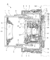
- the camera A which is the image pickup apparatus of the present embodiment, includes a camera body 100 and a lens barrel 1 that can be attached to and detached from the camera body 100.
- the camera body 100 contains, for example, an image sensor such as a CCD that captures a subject image via the lens barrel 1, an AF circuit for performing a focus operation, a camera CPU that controls the operation of the camera A, and various data. It is equipped with a microprocessor having a memory for storing.
- the lens barrel 1 of the present embodiment is provided on the image plane side / imaging side on the rear side in the axis O1 direction (optical axis O1 direction), and has a substantially annular mount portion 2 for connecting to the camera body 100 and a mount.
- a fixed cylinder 3 is coaxially provided by connecting and fixing the rear end portion to the portion 2, and the fixed cylinder 3 is coaxially arranged on the outer side in the radial direction and rotates at a predetermined angle (zoom rotation angle) around the axis O1.
- a zoom operation ring 4 provided as possible, a zoom ring interlocking ring 5 coaxially arranged inside the fixed cylinder 3 in the radial direction and rotating in conjunction with the zoom operation ring 4, and a radial direction of the zoom ring interlocking ring 5.
- a straight-moving cylinder 6 coaxially arranged on the inside and movable forward and backward in the axis O1 direction, and a first coaxially arranged on the inside in the radial direction of the straight cylinder 6 and movable forward and backward in the axis O1 direction.
- the moving cylinder 7 and the cam cylinder 8 coaxially arranged inside the first moving cylinder 7 in the radial direction and movable forward and backward in the axis O1 direction, and arranged coaxially inside the cam cylinder 8 in the radial direction.
- the second moving cylinder 9 is provided so as to be able to move forward and backward in the axis O1 direction
- the third movement is coaxially arranged inside the second moving cylinder 9 in the radial direction and is provided so as to be movable forward and backward in the axis O1 direction. It is provided with a cylinder 10.
- the lens barrel 1 of the present embodiment has four lenses, the first lens group L1, the second lens group L2, the third lens group L3, and the fourth lens group L4, in order from the subject side on the front side in the axis O1 direction. It has a group.
- the fixed cylinder 3 is formed by providing a straight groove extending along the axis O1 direction.
- the straight cylinder 6 is provided with a cam groove and a straight key on the inner diameter side.
- the cam cylinder 8 is provided with a first cam groove for moving the first lens group L1 forward and backward in the axis O1 direction on the outer diameter side, and the second lens group L2 and the third lens group L3 are provided on the inner diameter side, respectively.
- a second cam groove and a third cam groove for moving forward and backward in the axis O1 direction are provided.
- the cam cylinder 8 is provided with a follower that slides in contact with the cam groove of the straight cylinder 6.
- the first lens group L1 includes a lens and a first lens holding frame 15 for holding the lens, and has a first moving cylinder 7 provided with a follower engaged with a first cam groove of the cam cylinder 8. 1
- the lens holding frame 15 is screw-fixed and arranged.
- the second lens group L2 includes a lens and a second lens holding frame 16 for holding the lens, and has a third moving cylinder 10 provided with a follower engaged with a second cam groove of the cam cylinder 8. 2
- the lens holding frame 16 is fixed and arranged with screws.
- the third lens group L3 is a focus lens group, and includes a lens and a third lens holding frame 17 for holding the lens, and is provided by engaging a follower with a third cam groove of the cam cylinder 8.
- a third lens holding frame 17 is screw-fixed to the moving cylinder 9 and arranged.
- the fourth lens group L4 includes a lens and a fourth lens holding frame 18 for holding the lens, and the fourth lens holding frame 18 is screw-fixed to a mount portion 2 or the like.
- the second lens group L2 is provided with an aperture unit (aperture mechanism) 20 and a VR unit (camera shake correction mechanism) 21 controlled by a motor drive.
- the diaphragm unit 20 includes, for example, an annular press plate, an annular rotating member that rotates forward and reverse around the axis O1 by driving a stepping motor (aperture drive unit), and an opening that follows the rotation of the rotating member.
- the size, that is, the diaphragm is adjusted.
- nine diaphragm blades and an annular cam member are provided, and the diaphragm blades are interlocked with the drive of the diaphragm drive unit to adjust the size of the opening.
- a control device (CPU, control unit) 30 for controlling the drive of the aperture drive unit is arranged (mounted) on the main board M2 described later (FIG. 5A, etc.). Further, the main board M2 and the diaphragm drive unit are connected by a flexible board.
- the VR unit 21 reduces the image blur of the subject image caused by the vibration of the lens barrel 1 by shifting the VR lens of the second lens group L2 in the direction orthogonal to the optical axis.
- VR It includes a position detection sensor that detects the position of the lens and an actuator (VR drive unit) that displaces the VR lens according to the detection result of the position detection sensor.
- the VR drive unit includes, for example, a magnet and a coil, and is configured so that the VR lens can be shifted and moved in a direction perpendicular to the optical axis by controlling the energization of the coil.
- the control device (CPU, control unit) 30 for controlling the drive of the VR drive unit is arranged (mounted) on the main board M2 described later. Further, the main board M2 and the VR drive unit are connected by a flexible board.
- the third lens group L3 of the focus lens group includes a stepping motor (focus drive unit), a lead screw, a rack, etc., and is located in the optical axis direction of the lens barrel relative to the other lens groups.
- a focus drive mechanism 22 for driving forward and backward is provided.
- the control device (CPU, control unit) 30 for controlling the drive of the focus drive unit is arranged (mounted) on the main board M2 described later. Further, the main board M2 and the focus drive unit are connected by a flexible board.
- the control device for controlling the aperture drive unit, the control device for controlling the VR drive unit, and the control device for controlling the focus drive unit may be the same or may be provided separately.
- the first lens group L1, the second lens group L2, and the third lens group L3 move in the axis O1 direction along the first cam groove, the second cam groove, and the third cam groove, respectively. Move forward and backward. In this way, the first lens group L1, the second lens group L2, and the third lens group L3 move in the optical axis direction in the axis O1 direction, and the distance between the lens groups L1 to L4 fluctuates to zoom. ..
- the positions of the lens groups L1 to L4 and the in-line cylinder 6 by zooming are determined by the sum of the extension amount of the cam cylinder 8 and the extension amount of each lens group L1 to L4 with respect to the cam cylinder 8.
- the fourth lens group L4 is fixed.
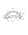
- the lens barrel 1 is mechanically connected to the camera body 100 via the mount portion 2, and is provided as a contact terminal connected and supported by the mount portion 2.
- the (contact, contact portion) 25 (see FIGS. 5 and 6) and the contact terminal (contact, contact portion) of the camera body 100 are in contact with each other and are electrically connected, and power is supplied from the camera body 100.
- a communication unit is connected to the contact terminal 25, and information is transmitted and received between the lens barrel 1 and the camera body 100 via the contact terminal 25.
- the lens barrel 1 has a contact block having a plurality of contact terminals 25 and pins 26 for electrically and mechanically connecting the contact terminals 25 to the main substrate M2 described later.
- 27 is provided by positioning and fixing to the mount portion 2.
- the contact portion is composed of the contact terminal 25 and the pin 26 (contact block 27).
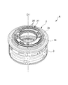
- a contact block receiver 31 that supports the contact block 27, a substrate receiver 32 that supports the main substrate M2, and an elastic member are arranged on the inner diameter side of the mount portion 2.
- the cushion base 33 is formed so as to project in the radial direction.
- the contact block 27 is arranged so as to be supported by the contact block receiver 31, and is screwed to the mount portion 2 by the contact block screw hole 34.
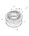
- the main board M2 is soldered to the contact block 27 as described later, and is arranged on the inner diameter side of the contact surface 2a described later as shown in FIG. 6B. Further, an elastic member (not shown) is arranged on the cushion base 33, and the main substrate M2 is arranged with the elastic member sandwiched between the elastic member and the cushion base 33 in the optical axis direction O1.
- the cushion base 33 is provided at three places.
- the main board M2 has a gap between it and the board receiver 32.
- the main substrate M2 is stably fixed by the substrate retainer 35. Specifically, the substrate retainer 35 is arranged so as to press the main substrate M2 from the image plane side to the subject side.
- the elastic member arranged on the cushion base 33 is crushed, and the main substrate M2 and the substrate receiver 32 come into contact with each other. As long as the main board M2 is stably held, there may be a gap between the main board M2 and the board receiver 32.
- the substrate retainer 35 is screwed to the mount portion 2 by the substrate retainer screw holes 36 in a state where the main substrate M2 is pressed in the optical axis direction O1.
- the main board M2 and the contact block 27 can be stably attached to the mount portion 2. Further, since the main substrate M2 is not fixed with screws or the like, it becomes thin in the optical axis direction. Further, since the main board M2 is attached by being sandwiched between the board holder 35 and the mount portion 2 (an elastic member placed on the cushion base 33), vibration such as a shutter shock is not easily transmitted to the main board M2, and the control unit 30 Noise is hard to get on.
- the fourth lens holding frame 18 is arranged on the inner diameter side of the substrate retainer 35, and is screwed to the substrate retainer 35 and the mount portion 2.
- the lens barrel 1 is connected to the contact terminal 25, and for example, power supply, zooming (in the case of power zoom, the zoom motor (zoom drive unit) is controlled), focusing, aperture adjustment, and camera shake.
- a main board (board part) M2 equipped with wiring and a control device (CPU or the like) 30 for performing operation control (control of various drive parts) such as correction is housed.
- the main board M2 may have one control device 30 or a plurality of control devices 30.
- the main substrate M2 is formed in a substantially annular plate shape, is arranged coaxially with the lens barrel 1, and has a mount portion 2. It is provided so as to be arranged on the inner diameter side of the contact surface (surface, mount surface) 2a that comes into contact with the camera body 100 of the above. Further, the main substrate M2 is arranged on the image plane side of the contact surface 2a of the mount portion 2 in the optical axis direction in the axis O1 direction. Further, the main substrate M2 is arranged between the fourth lens group L4 and the contact surface 2a in the radial direction centered on the optical axis.
- the main substrate M2 does not necessarily have to be formed in a substantially annular plate shape.
- the surface 2a is an annular surface, which is a reference surface that comes into contact with each other when the lens barrel 1 and the camera body 100 are mounted.
- the fixed cylinder 3 and the mount portion 2 are connected via the surface 2a. For example, when the fixing cylinder 3 and the mounting portion 2 are fixed with screws, a hole through which the screws penetrate is provided in the mounting portion 2a.
- the pin 26 of the contact block 27 is directly connected to the main board M2, and the pin 26 is soldered to the main board M2.
- the contact block 27 and thus the plurality of contact terminals 25 are connected to the main board M2 via the pins 26.
- the contact block 27 has a radius of curvature substantially equal to the radius of curvature of the main board M2 and is formed in a substantially arc shape, and the outer peripheral edge 27a of the contact block 27 is placed at the position of the outer peripheral edge m1 of the main board M2.
- the contact block 27 is mounted on the main board M2 so as to be substantially matched.
- the pin 26 and the main board M2 do not necessarily have to be directly connected, and may be connected via a flexible board.
- the lens barrel 1 of the present embodiment requires a shorter flexible substrate than the conventional one, and the arrangement area (occupied area) of the flexible substrate is small. It's done.
- the distance T1 in the axis O1 direction from one end 25a on the subject side of the contact terminal 25 to one end (one surface) m2 on the image plane side of the main substrate M2 is on the image plane side of the mount portion 2.
- the distance from one end 2b to the contact surface (surface, mount surface) 2a of the mount portion 2 is shorter than the distance T2. In other words, the distance from the contact terminal 25 to the main board M2 is smaller than the width of the mount portion 2.
- the main board M2 is arranged on the inner diameter side of the contact surface 2a of the mount portion 2 in contact with the camera body 100, and is arranged on the image plane side of the contact surface 2a of the mount portion 2.
- the main substrate M2 arranged in this way can be attached to and detached from the lens barrel 1 even when the plurality of cylinders 3 to 10 and the mount portion 2 constituting the lens barrel 1 are assembled. it can. That is, the main substrate M2 can be attached to and detached from the lens barrel 1 without disassembling the plurality of cylinders 3 to 10 and the mount portion 2.
- the components for example, the fixed cylinder 3, the zoom operation ring 4, and the like
- the zoom ring interlocking ring 5, the straight-ahead cylinder 6, the cam cylinder 8, each group moving cylinder 7, 9, 10, etc. move in the image plane direction, but from the main board M2 in order to avoid collision with the main board M2. It cannot move to the image plane side.
- each configuration is configured. Since the parts cannot be moved to the image plane side from the main board, the length of the product of the lens barrel 1 becomes longer than that when the main board is arranged at the position of M2. For example, the length of the lens barrel 1 becomes longer as T3 shown in FIG. 4A.
- the main substrate M2 is provided so as to be arranged on the inner diameter side of the contact surface 2a in contact with the camera body 100 of the mount portion 2. ing. Further, the main substrate M2 is arranged on the image plane side of the contact surface 2a of the mount portion 2 in the optical axis direction in the axis O1 direction.
- the lens barrel 1 is secured while securing the area required for extending each lens group L1 to L3 (L4) to the optimum position. It becomes possible to make the length of the lens smaller than before.
- the lens barrel 1 and the camera A of the present embodiment it is possible to further reduce the size, thickness, and weight as compared with the conventional case.
- the lens barrel 1 and the camera A of the present embodiment are configured by directly connecting the pin 26 (contact portion) to the main board M2, a flexible board connecting the pin 26 and the main board M2 becomes unnecessary. can do. As a result, it is not necessary to consider the arrangement / movable area (occupied area) of the flexible substrate, and the lens barrel 1 can be made smaller, thinner, and lighter. In addition, it is possible to reduce the cost by eliminating the need for a flexible substrate.
- the flexible board is shorter than the conventional one, and the arrangement area (occupied area) of the flexible board is small. Therefore, the lens barrel 1 is still used. Can be made smaller, thinner, and lighter.
- the contact block 27 is mounted on the main board M2 so that the outer peripheral edge 27a of the contact block 27 is substantially aligned with the position of the outer peripheral edge m1 of the main board M2.
- the contact block 27 and the main substrate M2 can be handled integrally, and the ease of handling and fitting of the lens barrel 1 for assembly and removal can be improved.
- the distance T1 in the axis O1 direction from one end 25b on the subject side of the contact terminal 25 to one end (one surface) m2 on the image plane side of the main substrate M2 is the mount portion 2.
- the distance from one end 2b on the image plane side to the contact surface (plane, mount surface) 2a of the mount portion 2 is shorter than the distance T2.
- one ends 8a and 9a on the image plane side of the cylinders are mounted on the mount portion 2 in the retracted state shown in FIG. It can be arranged on the image plane side in the optical axis O1 direction rather than one end 2c on the subject side. This makes it possible to further reduce the size, thickness, and weight.
- the main board M2 is arranged on the inner diameter side of the contact surface 2a of the mount portion 2 in contact with the camera body 100, and is arranged on the image plane side of the contact surface 2a of the mount portion 2. There is. As a result, the main substrate M2 can be individually attached to and detached from the state in which the plurality of cylinders 3 to 10 and the mount portion 2 constituting the lens barrel 1 are assembled.
- the main substrate M2 after assembling the various cylinders 3 to 10 and the mount portion 2, which facilitates the assembly of the lens barrel 1. Can be done. Further, when performing maintenance or parts replacement of the lens barrel 1, especially when replacing the main board M2, the main board M2 is removed without disassembling and removing the various cylinders 3 to 10 and the mount portion 2. Will be possible. This makes it possible to improve the efficiency of the manufacturing process and maintainability.
- the present invention is not limited to the above-mentioned one embodiment, and can be appropriately changed without departing from the spirit thereof, and any combination can be used. Good.
- a biaxial gyro sensor, an acceleration sensor, or the like is mounted on the main substrate M2 arranged on the rear side of the lens barrel 1 of the present embodiment in the optical axis O1 direction, camera shake can be prevented more accurately and accurately. It becomes possible to plan. That is, it is possible to realize more accurate and highly reliable detection performance and camera shake correction performance.
- the number and configuration of the lens group and the tubular body (ring body) do not need to be limited as in the present embodiment.
- Lens barrel 2 Mount 2a surface (contact surface, mount surface) 2b One end on the imaging surface side 2c One end on the subject side 3 Fixed cylinder 4 Zoom operation ring 5 Zoom ring interlocking ring 6 Straight cylinder 7 First moving cylinder (first moving ring) 8 Cam cylinder (cam ring) 9 Second moving cylinder (second moving ring) 10 Third moving cylinder (third moving ring) 20 Aperture unit (aperture mechanism) 21 VR unit (camera shake correction mechanism) 22 Focus drive mechanism 25 Contact terminals (contacts, contacts) 25a One end of the contact terminal on the subject side, pin 26 (contact part) 27 Contact block 27a Outer peripheral edge 27b One end on the subject side 30 Control device (control unit) 31 Contact block receiver 32 Board receiver 33 Cushion stand 34 Contact block screw hole 35 Board retainer 36 Board retainer screw hole 100 Camera body A Camera (imaging device) M1 Conventional main board M2 Main board (board part) m1 Outer peripheral edge m2 One end on the image plane side O1 Axis line, optical axis L1 1s
Landscapes
- Physics & Mathematics (AREA)
- General Physics & Mathematics (AREA)
- Optics & Photonics (AREA)
- Lens Barrels (AREA)
Priority Applications (1)
| Application Number | Priority Date | Filing Date | Title |
|---|---|---|---|
| JP2021515916A JPWO2020217870A1 (https=) | 2019-04-22 | 2020-03-30 |
Applications Claiming Priority (2)
| Application Number | Priority Date | Filing Date | Title |
|---|---|---|---|
| JP2019081112 | 2019-04-22 | ||
| JP2019-081112 | 2019-04-22 |
Publications (1)
| Publication Number | Publication Date |
|---|---|
| WO2020217870A1 true WO2020217870A1 (ja) | 2020-10-29 |
Family
ID=72942528
Family Applications (1)
| Application Number | Title | Priority Date | Filing Date |
|---|---|---|---|
| PCT/JP2020/014586 Ceased WO2020217870A1 (ja) | 2019-04-22 | 2020-03-30 | レンズ鏡筒及び撮像装置 |
Country Status (2)
| Country | Link |
|---|---|
| JP (1) | JPWO2020217870A1 (https=) |
| WO (1) | WO2020217870A1 (https=) |
Cited By (1)
| Publication number | Priority date | Publication date | Assignee | Title |
|---|---|---|---|---|
| CN113114918A (zh) * | 2021-04-30 | 2021-07-13 | 维沃移动通信有限公司 | 一种摄像头及电子设备 |
Citations (2)
| Publication number | Priority date | Publication date | Assignee | Title |
|---|---|---|---|---|
| JP2006267697A (ja) * | 2005-03-24 | 2006-10-05 | Fuji Photo Film Co Ltd | デジタルカメラ及びレンズユニット |
| WO2014115760A1 (ja) * | 2013-01-25 | 2014-07-31 | オリンパスイメージング株式会社 | レンズ鏡筒 |
Family Cites Families (9)
| Publication number | Priority date | Publication date | Assignee | Title |
|---|---|---|---|---|
| JP2001116972A (ja) * | 1999-10-19 | 2001-04-27 | Canon Inc | 交換レンズ鏡筒の電気配線装置 |
| JP2007288359A (ja) * | 2006-04-13 | 2007-11-01 | Fujifilm Corp | デジタルカメラ |
| JP2008046332A (ja) * | 2006-08-15 | 2008-02-28 | Fujifilm Corp | レンズユニット及びデジタルカメラ |
| JP2010164872A (ja) * | 2009-01-19 | 2010-07-29 | Sigma Corp | 交換レンズ |
| JP2011145322A (ja) * | 2010-01-12 | 2011-07-28 | Panasonic Corp | 交換レンズユニットおよびデジタルカメラ |
| JP5234188B2 (ja) * | 2010-01-14 | 2013-07-10 | パナソニック株式会社 | デジタルカメラおよび交換レンズユニット |
| WO2012107965A1 (ja) * | 2011-02-09 | 2012-08-16 | パナソニック株式会社 | レンズ鏡筒および撮像装置 |
| JP6084524B2 (ja) * | 2013-06-25 | 2017-02-22 | 株式会社シグマ | 交換レンズ |
| JP6485026B2 (ja) * | 2014-12-16 | 2019-03-20 | コニカミノルタ株式会社 | レンズ鏡胴 |
-
2020
- 2020-03-30 JP JP2021515916A patent/JPWO2020217870A1/ja active Pending
- 2020-03-30 WO PCT/JP2020/014586 patent/WO2020217870A1/ja not_active Ceased
Patent Citations (2)
| Publication number | Priority date | Publication date | Assignee | Title |
|---|---|---|---|---|
| JP2006267697A (ja) * | 2005-03-24 | 2006-10-05 | Fuji Photo Film Co Ltd | デジタルカメラ及びレンズユニット |
| WO2014115760A1 (ja) * | 2013-01-25 | 2014-07-31 | オリンパスイメージング株式会社 | レンズ鏡筒 |
Cited By (2)
| Publication number | Priority date | Publication date | Assignee | Title |
|---|---|---|---|---|
| CN113114918A (zh) * | 2021-04-30 | 2021-07-13 | 维沃移动通信有限公司 | 一种摄像头及电子设备 |
| CN113114918B (zh) * | 2021-04-30 | 2022-12-23 | 维沃移动通信有限公司 | 一种摄像头及电子设备 |
Also Published As
| Publication number | Publication date |
|---|---|
| JPWO2020217870A1 (https=) | 2020-10-29 |
Similar Documents
| Publication | Publication Date | Title |
|---|---|---|
| JP7157314B2 (ja) | カメラモジュール、及びカメラ搭載装置 | |
| US7414802B2 (en) | Lens apparatus and camera | |
| JP4764075B2 (ja) | 像ぶれ補正装置、該像ぶれ補正装置を備えたレンズ鏡筒 | |
| CN103748492A (zh) | 透镜镜筒 | |
| WO2019064946A1 (ja) | レンズ鏡筒及び撮像装置 | |
| JP4750402B2 (ja) | 光学機器 | |
| US11487075B2 (en) | Lens apparatus and imaging apparatus | |
| WO2020217870A1 (ja) | レンズ鏡筒及び撮像装置 | |
| JP2016109750A (ja) | レンズ鏡胴及び撮像装置 | |
| US9936136B2 (en) | Lens barrel | |
| JP2025047841A (ja) | 光学機器 | |
| JP7566644B2 (ja) | レンズ装置、撮像装置、及び撮像システム | |
| JP6448186B2 (ja) | レンズ鏡筒およびこれを備えた光学機器 | |
| JP2008107533A (ja) | レンズ鏡筒の調整構造 | |
| JP7616318B2 (ja) | レンズ鏡筒及び撮像装置 | |
| JP6460667B2 (ja) | 光学機器 | |
| JP2015203751A (ja) | レンズ鏡筒および撮像装置 | |
| JP2019159081A (ja) | レンズ装置およびそれを備えた撮像装置 | |
| JP7721361B2 (ja) | 光学機器、レンズ鏡筒及び撮像装置 | |
| JP2007241103A (ja) | 撮像装置およびレンズ装置 | |
| JP6958662B2 (ja) | レンズ鏡筒および撮像装置 | |
| JP2020034854A (ja) | レンズ装置、及び、カメラシステム | |
| JP2002196206A (ja) | レンズ鏡筒およびカメラ | |
| JP4731854B2 (ja) | 光学機器 | |
| JP2025047840A (ja) | 光学機器 |
Legal Events
| Date | Code | Title | Description |
|---|---|---|---|
| 121 | Ep: the epo has been informed by wipo that ep was designated in this application |
Ref document number: 20794726 Country of ref document: EP Kind code of ref document: A1 |
|
| ENP | Entry into the national phase |
Ref document number: 2021515916 Country of ref document: JP Kind code of ref document: A |
|
| NENP | Non-entry into the national phase |
Ref country code: DE |
|
| 122 | Ep: pct application non-entry in european phase |
Ref document number: 20794726 Country of ref document: EP Kind code of ref document: A1 |