WO2020209177A1 - ジョイントコネクタ - Google Patents
ジョイントコネクタ Download PDFInfo
- Publication number
- WO2020209177A1 WO2020209177A1 PCT/JP2020/015214 JP2020015214W WO2020209177A1 WO 2020209177 A1 WO2020209177 A1 WO 2020209177A1 JP 2020015214 W JP2020015214 W JP 2020015214W WO 2020209177 A1 WO2020209177 A1 WO 2020209177A1
- Authority
- WO
- WIPO (PCT)
- Prior art keywords
- lower housing
- electric wire
- upper cover
- holding portion
- terminal
- Prior art date
- Legal status (The legal status is an assumption and is not a legal conclusion. Google has not performed a legal analysis and makes no representation as to the accuracy of the status listed.)
- Ceased
Links
Images


Classifications
-
- H—ELECTRICITY
- H01—ELECTRIC ELEMENTS
- H01R—ELECTRICALLY-CONDUCTIVE CONNECTIONS; STRUCTURAL ASSOCIATIONS OF A PLURALITY OF MUTUALLY-INSULATED ELECTRICAL CONNECTING ELEMENTS; COUPLING DEVICES; CURRENT COLLECTORS
- H01R13/00—Details of coupling devices of the kinds covered by groups H01R12/70 or H01R24/00 - H01R33/00
- H01R13/62—Means for facilitating engagement or disengagement of coupling parts or for holding them in engagement
- H01R13/639—Additional means for holding or locking coupling parts together, after engagement, e.g. separate keylock, retainer strap
-
- H—ELECTRICITY
- H01—ELECTRIC ELEMENTS
- H01R—ELECTRICALLY-CONDUCTIVE CONNECTIONS; STRUCTURAL ASSOCIATIONS OF A PLURALITY OF MUTUALLY-INSULATED ELECTRICAL CONNECTING ELEMENTS; COUPLING DEVICES; CURRENT COLLECTORS
- H01R31/00—Coupling parts supported only by co-operation with counterpart
- H01R31/08—Short-circuiting members for bridging contacts in a counterpart
-
- H—ELECTRICITY
- H01—ELECTRIC ELEMENTS
- H01R—ELECTRICALLY-CONDUCTIVE CONNECTIONS; STRUCTURAL ASSOCIATIONS OF A PLURALITY OF MUTUALLY-INSULATED ELECTRICAL CONNECTING ELEMENTS; COUPLING DEVICES; CURRENT COLLECTORS
- H01R13/00—Details of coupling devices of the kinds covered by groups H01R12/70 or H01R24/00 - H01R33/00
- H01R13/58—Means for relieving strain on wire connection, e.g. cord grip, for avoiding loosening of connections between wires and terminals within a coupling device terminating a cable
- H01R13/5833—Means for relieving strain on wire connection, e.g. cord grip, for avoiding loosening of connections between wires and terminals within a coupling device terminating a cable the cable being forced in a tortuous or curved path, e.g. knots in cable
-
- H—ELECTRICITY
- H01—ELECTRIC ELEMENTS
- H01R—ELECTRICALLY-CONDUCTIVE CONNECTIONS; STRUCTURAL ASSOCIATIONS OF A PLURALITY OF MUTUALLY-INSULATED ELECTRICAL CONNECTING ELEMENTS; COUPLING DEVICES; CURRENT COLLECTORS
- H01R25/00—Coupling parts adapted for simultaneous co-operation with two or more identical counterparts, e.g. for distributing energy to two or more circuits
- H01R25/16—Rails or bus-bars provided with a plurality of discrete connecting locations for counterparts
- H01R25/161—Details
- H01R25/162—Electrical connections between or with rails or bus-bars
-
- H—ELECTRICITY
- H01—ELECTRIC ELEMENTS
- H01R—ELECTRICALLY-CONDUCTIVE CONNECTIONS; STRUCTURAL ASSOCIATIONS OF A PLURALITY OF MUTUALLY-INSULATED ELECTRICAL CONNECTING ELEMENTS; COUPLING DEVICES; CURRENT COLLECTORS
- H01R4/00—Electrically-conductive connections between two or more conductive members in direct contact, i.e. touching one another; Means for effecting or maintaining such contact; Electrically-conductive connections having two or more spaced connecting locations for conductors and using contact members penetrating insulation
- H01R4/10—Electrically-conductive connections between two or more conductive members in direct contact, i.e. touching one another; Means for effecting or maintaining such contact; Electrically-conductive connections having two or more spaced connecting locations for conductors and using contact members penetrating insulation effected solely by twisting, wrapping, bending, crimping, or other permanent deformation
- H01R4/16—Electrically-conductive connections between two or more conductive members in direct contact, i.e. touching one another; Means for effecting or maintaining such contact; Electrically-conductive connections having two or more spaced connecting locations for conductors and using contact members penetrating insulation effected solely by twisting, wrapping, bending, crimping, or other permanent deformation by bending
-
- H—ELECTRICITY
- H01—ELECTRIC ELEMENTS
- H01R—ELECTRICALLY-CONDUCTIVE CONNECTIONS; STRUCTURAL ASSOCIATIONS OF A PLURALITY OF MUTUALLY-INSULATED ELECTRICAL CONNECTING ELEMENTS; COUPLING DEVICES; CURRENT COLLECTORS
- H01R4/00—Electrically-conductive connections between two or more conductive members in direct contact, i.e. touching one another; Means for effecting or maintaining such contact; Electrically-conductive connections having two or more spaced connecting locations for conductors and using contact members penetrating insulation
- H01R4/10—Electrically-conductive connections between two or more conductive members in direct contact, i.e. touching one another; Means for effecting or maintaining such contact; Electrically-conductive connections having two or more spaced connecting locations for conductors and using contact members penetrating insulation effected solely by twisting, wrapping, bending, crimping, or other permanent deformation
- H01R4/18—Electrically-conductive connections between two or more conductive members in direct contact, i.e. touching one another; Means for effecting or maintaining such contact; Electrically-conductive connections having two or more spaced connecting locations for conductors and using contact members penetrating insulation effected solely by twisting, wrapping, bending, crimping, or other permanent deformation by crimping
- H01R4/183—Electrically-conductive connections between two or more conductive members in direct contact, i.e. touching one another; Means for effecting or maintaining such contact; Electrically-conductive connections having two or more spaced connecting locations for conductors and using contact members penetrating insulation effected solely by twisting, wrapping, bending, crimping, or other permanent deformation by crimping for cylindrical elongated bodies, e.g. cables having circular cross-section
-
- H—ELECTRICITY
- H01—ELECTRIC ELEMENTS
- H01R—ELECTRICALLY-CONDUCTIVE CONNECTIONS; STRUCTURAL ASSOCIATIONS OF A PLURALITY OF MUTUALLY-INSULATED ELECTRICAL CONNECTING ELEMENTS; COUPLING DEVICES; CURRENT COLLECTORS
- H01R4/00—Electrically-conductive connections between two or more conductive members in direct contact, i.e. touching one another; Means for effecting or maintaining such contact; Electrically-conductive connections having two or more spaced connecting locations for conductors and using contact members penetrating insulation
- H01R4/24—Connections using contact members penetrating or cutting insulation or cable strands
- H01R4/2495—Insulation penetration combined with permanent deformation of the contact member, e.g. crimping
Definitions
- This disclosure relates to joint connectors.
- a joint connector described in JP-A-10-261471 is known.
- the retainer body of the retainer with a bus bar is provided in the terminal insertion port of each terminal storage chamber of the housing so as to be able to be fitted, and the retainer body is engaged with the engaging portion provided in the terminal insertion port of each terminal accommodation chamber.
- a locking portion to be stopped is provided, and the terminal of the bus bar of the retainer with a bus bar is freely locked to the locking portion of the joint terminal.
- the retainer main body of the retainer having the same shape as the retainer with a bus bar is provided so as to be freely fitted to the terminal insertion port of each terminal accommodating chamber of each housing.
- the present disclosure has been completed based on the above circumstances, and an object of the present disclosure is to provide a joint connector capable of suppressing transmission of an external force from an electric wire to a terminal.
- the present disclosure is a joint connector for connecting a plurality of electric wires, the plurality of electric wires extending along an extension direction, a plurality of terminals connected to front ends of the plurality of electric wires in the extension direction, and the above-mentioned.
- a lower housing for accommodating a plurality of terminals, a bus bar arranged in the lower housing, and an upper cover assembled to the lower housing are provided, and the bus bar has a plurality of tabs, and each of the plurality of terminals is provided.
- the electric wire has a bent portion that is folded forward in the extending direction
- the upper cover has an electric wire holding portion that holds the plurality of electric wires folded forward in the extending direction.
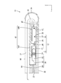
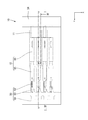
- FIG. 1 is a cross-sectional view showing a joint connector according to the first embodiment, and is a cross-sectional view taken along the line II in FIG.
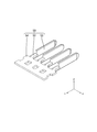
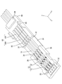
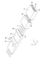
- FIG. 2 is a perspective view showing the lower housing, the hinge, and the upper cover.
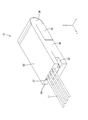
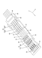
- FIG. 3 is a perspective view showing a joint connector.
- FIG. 4 is a perspective view showing a bus bar.
- FIG. 5 is a sectional view taken along line VV in FIG.
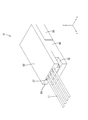
- FIG. 6 is a perspective view showing a state in which an electric wire is inserted through the upper cover.
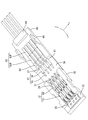
- FIG. 7 is a perspective view showing a state in which an electric wire is inserted through the terminal.
- FIG. 8 is a perspective view showing a state in which the electric wire and the terminal are electrically connected by moving the slide portion to the main locking position.
- FIG. 1 is a cross-sectional view showing a joint connector according to the first embodiment, and is a cross-sectional view taken along the line II in FIG.
- FIG. 2 is a perspective view
- FIG. 9 is a plan view showing a joint connector.
- FIG. 10 is a perspective view showing a joint connector according to the second embodiment.
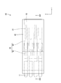
- FIG. 11 is a plan view showing a state before the lower housing and the upper cover are assembled.
- FIG. 12 is a perspective view showing a lower housing according to the third embodiment.
- FIG. 13 is a perspective view showing a state before the lower housing and the upper cover are assembled.
- FIG. 14 is a plan view showing a joint connector.
- FIG. 15 is a sectional view taken along line XV-XV in FIG.
- the present disclosure is a joint connector for connecting a plurality of electric wires, the plurality of electric wires extending along the extending direction and a plurality of terminals connected to the front ends of the plurality of electric wires in the extending direction.
- a lower housing for accommodating the plurality of terminals, a bus bar disposed in the lower housing, and an upper cover assembled to the lower housing.
- the bus bar has a plurality of tabs, and the plurality of tabs are provided.
- Each of the terminals has a bus bar connection portion to which the plurality of tabs are connected, and an electric wire connection portion to which the plurality of electric wires are connected, respectively, and is led out from the lower housing to the rear in the extension direction.
- the plurality of electric wires have a bent portion that is folded forward in the extending direction, and the upper cover has an electric wire holding portion that holds the plurality of electric wires in a state of being folded forward in the extending direction. ..
- the upper cover preferably has an electric wire holding portion that presses the plurality of electric wires led out from the lower housing to the rear in the extending direction toward the lower housing.
- the plurality of electric wires are pressed toward the lower housing by the electric wire holding portion of the upper cover, it is suppressed that the force applied to the electric wires is transmitted before the electric wire pressing portion. As a result, the external force applied to the electric wire is suppressed from being transmitted to the terminal.
- the upper cover is connected to the lower housing via a hinge extending from the rear of the lower housing in the extending direction.
- the lower housing and upper cover are connected via hinges, the number of parts can be reduced. Further, since the hinge protects a plurality of electric wires, it is possible to prevent an external force from being applied to the electric wires.
- the upper cover has a terminal engaging portion that engages with the terminal from behind in the extending direction in a state of being assembled to the lower housing.
- the terminal engaging portion engages with the terminal from the rear in the extending direction, the terminal moves backward in the extending direction even if the external force applied to the electric wire crosses the bent portion and reaches the electric wire connecting portion. Is being suppressed. As a result, the terminals are firmly held by the lower housing and the upper cover.
- the inner surface of the upper cover is provided with a bus bar holding portion that sandwiches the bus bar between the lower housing and the lower housing in a state where the lower housing and the upper cover are assembled.
- the bus bar can be held by a simple operation of assembling the lower housing and upper cover.
- the electric wire holding portion is preferably formed in a hole shape through which the electric wire is inserted.
- the electric wire By inserting the electric wire into the hole-shaped electric wire holding portion, the electric wire can be reliably held along the extending direction. Further, at least the portion of the electric wire arranged in the electric wire holding portion can be protected from an external force.
- the electric wire connecting portion extends along the extending direction and is arranged outside the sandwiching portion and can move along the extending direction as well as a sandwiching portion that sandwiches one of the plurality of electric wires. It is preferable that the slide portion has a slide portion, and the slide portion has a pressurizing portion that pressurizes the sandwiched portion toward the electric wire in a state where one of the plurality of electric wires is sandwiched between the sandwiched portions. ..
- the mold required for crimping the barrel to the outer circumference of the electric wire becomes unnecessary, and the manufacturing cost of the joint connector can be reduced. ..
- Embodiment 1 of the present disclosure will be described with reference to FIGS. 1-9.
- the joint connector 10 according to this embodiment electrically connects a plurality of electric wires 11.
- the direction indicated by the arrow Z will be on the top
- the direction indicated by the arrow Y will be the front
- the direction indicated by the arrow X will be on the left.
- a plurality of the same members only some of the members may be coded and the codes of other members may be omitted.
- the joint connector 10 has a plurality of electric wires 11 extending in the front-rear direction (an example of an extension direction) and a plurality of terminals connected to the front ends of the plurality of electric wires 11. 12, a bus bar 50 connected to a plurality of terminals 12, a lower housing 30 in which the plurality of terminals 12 and the bus bar 50 are housed, and an upper cover 60 attached to the upper portion of the lower housing 30 at the rear. ..
- the plurality of electric wires 11 are arranged so as to extend in the front-rear direction (an example of the extending direction).
- the outer circumference of the core wire 13 of the electric wire 11 is surrounded by an insulating coating 14 made of an insulating synthetic resin.
- the core wire 13 according to the present embodiment is made of one metal wire.
- the core wire 13 may be a stranded wire obtained by twisting a plurality of fine metal wires.
- any metal such as copper, copper alloy, aluminum, and aluminum alloy can be appropriately selected as needed.
- the core wire 13 according to this embodiment is made of copper or a copper alloy.
- the lower housing 30 has a rectangular parallelepiped shape that is flat in the vertical direction.
- a material containing an insulating synthetic resin is formed by injection molding.
- a plurality of cavities 29 (four in the present embodiment) extending in the front-rear direction are formed side by side in the left-right direction.
- the cavity 29 is opened upward so that the terminal 12 is arranged in the cavity 29 from above.
- Cavities 29 adjacent to each other in the left-right direction are separated by a partition wall 31 extending in the front-rear direction.
- the partition wall 31 electrically insulates the terminals 12 arranged in each cavity 29.
- the cavity 29 opens forward at the front end portion of the lower housing 30.
- a bus bar mounting portion 32 formed so as to be flush with the bottom wall of the cavity 29 and extending in the left-right direction is formed.
- the bus bar 50 is mounted on the bus bar mounting portion 32 from above.
- FIG. 1 the upper portion of the lower housing 30 is covered by the upper cover 60 assembled from above.
- the upper cover 60 is formed by injection molding an insulating synthetic resin.
- a lock claw 66 extending in the vertical direction is formed on the side edge of the upper cover 60. The lock claw 66 elastically engages with the lock receiving portion 33 provided on the side wall of the lower housing 30, so that the lower housing 30 and the upper cover 60 can be integrally assembled.
- the hinge 34 has a thin plate shape and is formed to be bendable.
- the upper cover 60 has an upper wall 61.
- a plurality of (four in this embodiment) electric wire holding portions 37 for holding the electric wires 11 are provided side by side on the upper wall 61 of the upper cover 60 in the left-right direction.
- the electric wire holding portion 37 is formed in a hole shape that penetrates the upper wall of the upper cover 60 in the front-rear direction.
- the inner diameter of the electric wire holding portion 37 is set to be the same as or larger than the outer diameter of the insulating coating 14 of the electric wire 11. As a result, the electric wire 11 is inserted into the electric wire holding portion 37.
- the front end portion of the upper wall 61 of the upper cover 60 is located downward at a position corresponding to the cavity 29 of the lower housing 30.
- a protruding bus bar holding portion 64 is formed.
- the bus bar holding portion 64 sandwiches the bus bar 50 with the bus bar mounting portion 32 of the lower housing 30.
- a connecting portion 54 which will be described later, is sandwiched between the bus bar holding portion 64 and the bus bar mounting portion 32. As a result, the bus bar 50 is held by the lower housing 30 and the upper cover 60.
- the terminal engaging portion 63 of (1) extends in the front-rear direction.
- the terminal engaging portion 63 includes a front terminal engaging portion 63F located on the front side and a rear terminal engaging portion 63R located on the rear portion of the front terminal engaging portion 63F.
- the rear terminal engaging portion 63R projects downward from the front terminal engaging portion 63F.
- the upper wall 61 is provided with a wire holding portion 65 projecting downward behind the terminal engaging portion 63.
- the electric wire pressing portion 65 comes into contact with the electric wire 11 led out rearward from the rear end portion of the terminal 12 from above, and presses the electric wire 11 from above toward the lower housing 30.
- the electric wire holding portion 65 is formed so as to extend in the left-right direction, and even when the electric wire 11 led out rearward from the terminal 12 is arranged at a position deviated from the cavity 29, the electric wire is reliably formed. It is designed to hold down 11.
- the bus bar 50 is formed by pressing a metal plate material into a predetermined shape.
- the metal plate material any metal such as copper and copper alloy can be appropriately selected.
- the bus bar 50 has a plurality of (four in this embodiment) tabs 52 extending rearward, and a connecting portion 54 connecting the front end portions of the tabs 52 via a relay portion 53.
- the tab 52 has a flat plate shape in the left-right direction.
- the connecting portion 54 has a flat plate shape in the vertical direction.
- the relay portion 53 is formed so as to extend rearward from the connecting portion 54. The right edge of the connecting portion 54 is bent downward and is connected to the tab 52.
- the terminal 12 includes a metal terminal body 15 and a slide portion 16 that can slide relative to the terminal body 15.
- Terminal body 15 The terminal body 15 is formed into a predetermined shape by a known method such as pressing, cutting, casting, or the like.
- metal constituting the terminal body 15 any metal such as copper, copper alloy, aluminum, aluminum alloy, and stainless steel can be appropriately selected as needed.
- the terminal body 15 according to this embodiment is made of copper or a copper alloy.
- a plating layer may be formed on the surface of the terminal body 15.
- any metal such as tin, nickel, and silver can be appropriately selected as required.
- the terminal body 15 according to this embodiment is tin-plated.
- the terminal body 15 has a tubular portion 17 (an example of a bus bar connecting portion) into which a tab 52 can be inserted and an electric wire connecting portion 20 located behind the tubular portion 17 and connected to the electric wire 11.
- the electric wire connecting portion 20 includes an upper holding portion 18A and a lower holding portion 18B extending rearward.
- the tubular portion 17 has a square tubular shape extending in the front-rear direction.
- the front end of the tubular portion 17 is opened so that the tab 52 can be inserted.
- FIG. 1 shows a part of the elastic contact piece 19 provided on the tubular portion 17.
- an elastic contact piece 19 that is elastically deformable is arranged inside the tubular portion 17.
- the elastic contact piece 19 extends inward from the inner wall of the tubular portion 17.
- the tab 52 inserted into the tubular portion 17 presses the elastic contact piece 19 to elastically deform it.
- the tab 52 is sandwiched between the inner wall of the tubular portion 17 and the elastic contact piece 19 due to the elastic force of the elastically deformed elastic contact piece 19. As a result, the tab 52 and the terminal 12 are electrically connected.
- a square tubular electric wire connecting portion 20 is provided behind the tubular portion 17.
- An upper holding portion 18A (an example of a holding portion) is provided at the rear end of the upper wall of the electric wire connecting portion 20 so as to extend rearward
- a lower holding portion is provided at the rear end of the lower wall of the electric wire connecting portion 20.
- 18B (an example of a holding portion) is provided so as to extend rearward.
- the upper holding portion 18A and the lower holding portion 18B have an elongated shape extending back and forth.
- the upper holding portion 18A and the lower holding portion 18B are formed to have substantially the same length dimension in the front-rear direction.
- an upper holding protrusion 23A protruding downward is provided at a position in front of the rear end portion.
- a lower holding protrusion 23B that projects upward is provided at the rear end of the upper surface of the lower holding portion 18B.
- the lower holding protrusion 23B and the upper holding protrusion 23A are provided at positions shifted in the front-rear direction.
- the core wire 13 and the terminal body 15 are electrically connected by contacting the metal surface with the upper holding portion 18A and the lower holding portion 18B.
- the slide portion 16 has a square tubular shape extending in the front-rear direction.
- the slide portion 16 is formed by a known method such as cutting, casting, or pressing, if necessary.
- any metal such as copper, copper alloy, aluminum, aluminum alloy, and stainless steel can be appropriately selected as needed.
- the slide portion 16 according to the present embodiment is not particularly limited, but is made of stainless steel.
- a plating layer may be formed on the surface of the slide portion 16.
- any metal such as tin, nickel, and silver can be appropriately selected as required.
- the cross section of the inner shape of the slide portion 16 is the same as or slightly larger than the cross section of the outer shape of the region of the terminal body 15 where the upper holding portion 18A and the lower holding portion 18B are provided. As a result, the slide portion 16 is arranged outside the region of the terminal body 15 where the upper holding portion 18A and the lower holding portion 18B are provided.
- an upper pressurizing portion 25A (an example of a pressurizing portion) projecting downward is provided on the lower surface of the upper wall of the slide portion 16.
- a lower pressurizing portion 25B (an example of the pressurizing portion) projecting upward is provided.
- a temporary locking receiving portion 26 is opened on the side wall of the slide portion 16 at a position closer to the front end portion in the front-rear direction. Further, on the side wall of the slide portion 16, the main locking receiving portion 27 is opened at a position behind the temporary locking receiving portion 26.
- the temporary locking receiving portion 26 and the main locking receiving portion 27 can be elastically locked with the locking projection 28 provided on the side wall of the terminal body 15.
- the state in which the locking projection 28 of the terminal body 15 and the temporary locking receiving portion 26 of the slide portion 16 are locked is a state in which the sliding portion 16 is held at the temporary locking position with respect to the terminal main body 15. ..
- the upper pressurizing portion 25A and the lower pressurizing portion 25B of the slide portion 16 are separated rearward from the rear end edges of the upper holding portion 18A and the lower holding portion 18B of the terminal body 15. Further, in this state, the distance between the upper holding portion 18A and the lower holding portion 18B is set to be larger than the diameter of the core wire 13.
- the slide portion 16 is locked at the main locking position with respect to the terminal main body 15. There is. As shown in FIG. 1, in this state, the upper pressurizing portion 25A of the slide portion 16 is in contact with the upper holding portion 18A from above the upper holding portion 18A. Further, the lower pressurizing portion 25B of the slide portion 16 is in contact with the lower holding portion 18B from below the lower holding portion 18B.
- the slide portion 16 is fitted into the region of the terminal body 15 where the upper holding portion 18A and the lower holding portion 18B are provided, and is fitted into the above-mentioned temporary locking position and the main locking. It can be slid to and from the position.
- the upper holding portion 18A is pressed by the upper pressing portion 25A from above to press the upper holding portion 18A. Is designed to deform downward. Further, the lower pressing portion 25B presses the lower holding portion 18B from below, so that the lower holding portion 18B is deformed upward. As a result, the core wire 13 is arranged in the space between the upper holding portion 18A and the lower holding portion 18B in a state of being extended in the front-rear direction (extending direction), and the slide portion 16 is arranged with respect to the terminal body 15.
- the core wire 13 is sandwiched from the vertical direction by the elastically deformed upper holding portion 18A and the lower holding portion 18B. That is, the upper holding portion 18A comes into contact with the core wire 13 from above by being pressed downward by the upper pressing portion 25A, and the lower holding portion 18B is pressed upward by the lower pressing portion 25B to bring the core wire 13 into contact. It comes in contact with the cable from below.
- the upper holding protrusion 23A of the upper holding portion 18A presses the core wire 13 from above, and the lower side.
- the lower holding protrusion 23B of the holding portion 18B presses the core wire 13 from below.
- the core wire 13 is pressed from above by the upper holding protrusion 23A and is pressed from below by the lower holding protrusion 23B arranged at a position deviated from the upper holding protrusion 23A in the front-rear direction. Therefore, it is held in a bent state in the vertical direction (an example of a direction intersecting the extending direction).
- the core wire 13 and the terminal 12 are also electrically connected by the upper holding protrusion 23A and the lower holding protrusion 23B.
- a jig contact portion 46 projecting upward from the upper wall is provided at the front end portion of the slide portion 16.
- a jig comes into contact with the jig contact portion 46 from the rear, and the slide portion 16 is pushed forward by this jig, so that the slide portion 16 can move forward.
- a pair of invitation portions 47 projecting inward of the slide portion 16 are provided on the left and right side walls.
- the invitation portion 47 is formed narrower from the rear to the front.
- the front terminal engaging portion 63F engages with the cylinder portion 17 from above, and the cylinder portion 17 moves upward. It suppresses movement.
- the rear terminal engaging portion 63R engages with the slide portion 16 from above to prevent the slide portion 16 from moving upward.
- the front end portion of the rear terminal engaging portion 63R engages the jig contact portion of the slide portion 16 from the rear to prevent the slide portion 16 and the terminal body 15 from moving rearward.
- the front end portion of the electric wire holding portion 65 is engaged with the rear end portion of the slide portion 16 from the rear to prevent the slide portion 16 and the terminal body 15 from moving rearward.
- the terminal body 15 and the slide portion 16 are formed by a known method.
- the slide portion 16 is assembled from the rear to the terminal body 15.
- the front end edge of the slide portion 16 comes into contact with the locking projection 28 of the terminal body 15 from the rear, and the side wall of the slide portion 16 is expanded and deformed.
- the slide portion 16 is further pushed forward, the side wall of the slide portion 16 is restored and deformed, and the temporary locking receiving portion 26 of the slide portion 16 is locked to the locking projection 28 of the terminal body 15.
- the slide portion 16 is held at the temporarily locked position with respect to the terminal body 15.
- the terminal 12 is obtained.
- the lower housing 30 and the upper cover 60 are integrally formed via the hinge 34. As shown in FIG. 2, the lower housing 30 and the upper cover 60 are arranged so as to be arranged in the front-rear direction via the hinge 34.
- the tab 52 of the bus bar 50 is inserted into the tubular portion 17 from the front.
- the tab 52 and the elastic piece come into contact with each other, the tab 52 and the terminal 12 are electrically connected.
- the plurality of terminals 12 are electrically connected via the bus bar 50.
- the terminal 12 connected to the bus bar 50 is inserted into the cavity 29 of the lower housing 30 from above.
- the core wire 13 of the electric wire 11 is exposed by peeling the insulating coating 14 by a known method.
- the electric wire 11 is inserted into the electric wire holding portion 37 of the upper cover 60 from the rear with the core wire 13 on the front side.
- the cavity 29 is located in front of each electric wire holding portion 37.
- the electric wire 11 inserted through the electric wire holding portion 37 enters each cavity 29.
- the jig (not shown) is brought into contact with the jig contact portion 46 from the rear, and the slide portion 16 is slid forward.
- the slide portion 16 is moved forward relative to the terminal body 15.
- the locking projection 28 of the terminal body 15 and the temporary locking receiving portion 26 of the slide portion 16 are disengaged, and the side wall of the slide portion 16 rides on the locking projection 28 to expand and deform.
- the upper pressurizing portion 25A of the slide portion 16 abuts on the upper holding portion 18A of the terminal body 15 from above and presses downward.
- the lower pressurizing portion 25B of the slide portion 16 abuts on the lower holding portion 18B of the terminal body 15 from below and presses it upward.
- the core wire 13 is sandwiched between the upper sandwiching portion 18A and the lower sandwiching portion 18B from above and below (see FIG. 1).
- the core wire 13 is sandwiched between the lower surface of the upper holding portion 18A and the upper surface of the lower holding portion 18B, the oxide film formed on the surface of the core wire 13 is peeled off, and the core wire 13 is removed. The constituent metal surface is exposed.
- the electric wire 11 and the terminal 12 are electrically connected by contacting the metal surface with the upper holding portion 18A and the lower holding portion 18B. As a result, the plurality of electric wires 11 are electrically connected via the terminal 12 and the bus bar 50 (see FIG. 9).
- the core wire 13 In a state where the core wire 13 is sandwiched between the upper holding portion 18A and the lower holding portion 18B from above and below, the core wire 13 has the upper holding protrusion 23A of the upper holding portion 18A and the lower holding protrusion 18B of the lower holding portion 18B.
- the cable By being sandwiched between the 23B and 23B, the cable is held in a state of being extended in the front-rear direction and in a state of being bent in the vertical direction.
- the core wire 13 can be firmly held, so that when a tensile force acts on the electric wire 11, the holding force between the electric wire 11 and the terminal 12 can be increased.
- the upper cover 60 is assembled to the lower housing 30 from above the lower housing 30 while bending the hinge 34 into a C shape when viewed from the side.
- the lower housing 30 and the upper cover 60 are integrally assembled by elastically engaging the lock claw 66 of the upper cover 60 and the lock receiving portion 33 of the lower housing 30.
- the electric wire 11 led out to the rear of the lower housing 30 bends from above to the front and extends forward.
- a portion of the electric wire 11 that is bent in a C shape behind the lower housing 30 and the upper cover 60 is a bent portion 35.
- the electric wire 11 is held in the electric wire holding portion 37 of the upper cover 60 in a state of extending forward. This completes the joint connector 10.
- this embodiment there are 10 joint connectors for connecting a plurality of electric wires 11, a plurality of electric wires 11 extending in the front-rear direction, a plurality of terminals 12 connected to the front ends of the plurality of electric wires 11, and a plurality of terminals 12, respectively.
- a lower housing 30 accommodating a plurality of terminals 12, a bus bar 50 arranged in the lower housing 30, and an upper cover 60 assembled to the lower housing 30 are provided, and the bus bar 50 has a plurality of tabs 52 and has a plurality of tabs 52.
- Each of the terminals 12 has a tubular portion 17 into which a plurality of tabs 52 are inserted, and an electric wire connecting portion 20 to which the plurality of electric wires 11 are connected, respectively, and a plurality of terminals 12 are led out rearward from the lower housing 30.
- the electric wire 11 of the above is folded forward, and the upper cover 60 has an electric wire holding portion 37 for holding the plurality of electric wires 11 in a state of being folded forward.
- the upper cover has an electric wire holding portion 65 that presses a plurality of electric wires 11 led out rearward from the lower housing toward the lower housing 30.
- the force applied to the electric wires 11 may be transmitted before the electric wire pressing portions 65. It is suppressed. As a result, the external force applied to the electric wire 11 is suppressed from being transmitted to the terminal 12.
- the upper cover 60 is connected to the lower housing 30 via a hinge 34 extending from the rear of the lower housing 30.
- the hinge 34 Since the lower housing 30 and the upper cover 60 are connected via the hinge 34, the number of parts can be reduced. Further, since the hinge 34 is located outside the plurality of electric wires 11, the plurality of electric wires 11 are protected, so that external force is suppressed from being applied to the electric wires 11 themselves.
- the upper cover 60 has a terminal engaging portion 63 that engages with the terminal 12 from the rear in a state of being assembled to the lower housing 30.
- the terminal engaging portion 63 is engaged with the terminal 12 from the rear in the extending direction, even if the external force applied to the electric wire 11 exceeds the bent portion 35 and reaches the electric wire connecting portion 20, the terminal 12 remains. It is designed to prevent backward movement. As a result, the terminal 12 is firmly held by the lower housing 30 and the upper cover 60.
- a bus bar holding portion 64 for sandwiching the bus bar 50 between the lower housing 39 and the lower housing 39 is provided on the lower surface of the upper cover 60 in a state where the lower housing 39 and the upper cover 60 are assembled. ..
- the bus bar 50 can be held by a simple operation of assembling the lower housing 39 and the upper cover 60.
- the electric wire holding portion 37 is formed in a hole shape through which the electric wire 11 is inserted.
- the electric wire 11 By inserting the electric wire 11 through the electric wire holding portion 37 having a hole shape, the electric wire 11 can be reliably held along the front-rear direction. Further, at least the portion of the electric wire 11 arranged in the electric wire holding portion 37 can be protected from an external force.
- the electric wire connecting portion 20 extends along the front-rear direction and sandwiches one of the plurality of electric wires 11 with the upper sandwiching portion 18A and the lower sandwiching portion 18B, and the upper sandwiching portion 18A and the lower sandwiching portion 18A.
- the slide portion 16 has a slide portion 16 arranged on the outside of the portion 18B and movable in the front-rear direction, and the slide portion 16 has one of a plurality of electric wires 11 on the upper holding portion 18A and the lower holding portion 18B. It has an upper pressing portion 25A and a lower pressing portion 25B that pressurize the upper holding portion 18A and the lower holding portion 18B toward the electric wire 11 in a sandwiched state.
- the barrel is crimped to the outer circumference of the electric wire 11.
- the mold required for this is not required, and the manufacturing cost of the joint connector 10 can be reduced.
- Embodiment 2 of the present disclosure will be described with reference to FIGS. 10 to 11.
- the joint connector 70 according to the present embodiment is not provided with a hinge for connecting the lower housing 30 and the upper cover 60, and the lower housing 30 and the upper cover 60 are configured as separate parts.
- the electric wire 11 is inside the electric wire holding portion 37 of the upper cover 60 in a state where the lower housing 30 and the upper cover 60 are arranged in the front-rear direction by a jig (not shown). It is inserted into the terminal 12 housed in the cavity 29 of the lower housing 30.
- the joint connector 80 includes a lower housing 81, an upper cover 82 assembled to the lower housing 81 from above, a bus bar 83 arranged in the lower housing 81, and a terminal 84 arranged in the lower housing 81. To be equipped with.
- the lower housing 81 has a rectangular parallelepiped shape that is flat in the vertical direction.
- a plurality of cavities 85 (four in the present embodiment) penetrating in the front-rear direction are formed side by side in the left-right direction.
- a notch 86 notched upward is provided near the center position in the front-rear direction of the lower housing 81. The cavity 85 is exposed upward from the notch 86.
- a bus bar insertion hole 87 into which the bus bar 83 is inserted from the front is formed at the front end of the lower housing 81 so as to extend in the left-right direction.
- the height dimension of the bus bar insertion hole 87 in the vertical direction is formed to be the same as or slightly larger than the thickness dimension of the bus bar 83.
- a plurality of (four in this embodiment) die-cutting holes 88 are formed above the bus bar insertion holes 87 so as to extend in the front-rear direction.
- a lance 89 that elastically engages with the terminal 84 to hold the terminal 84 in the cavity 85 is formed inside each die-cutting hole 88.
- the lance 89 has a shape extending forward from the upper wall of the cavity 85. The front end portion of the lance 89, the terminal 84, and the upper wall of the tubular portion 90 are intertwined with each other.
- the terminal 84 has a tubular portion 90 into which a plurality of tabs 91 provided on the bus bar 83 are inserted, and an electric wire connecting portion 92 provided behind the tubular portion 90, respectively.
- the electric wire connecting portion 92 has a so-called barrel shape, and electrically connects the electric wire 11 and the terminal 84 by crimping to the outer circumference of the electric wire 11.
- a plurality of (four in this embodiment) electric wire holding portions 93 are formed on the upper cover 82 so as to extend in the front-rear direction.
- the electric wire holding portion 93 is formed in a hole shape that penetrates the upper cover 82 in the front-rear direction.
- the upper cover 82 is formed with elastically deformable lock claws 94 protruding in the vertical direction in the vicinity of the central position in the front-rear direction, corresponding to the notch 86 of the lower housing 81.
- the lower housing 81 and the upper cover 82 are integrally assembled by the lock claws 94 being arranged on the left and right sides of the notch 86 of the lower housing 81 and elastically engaging with the lower end edge of the cavity 85. It has become like.
- the upper cover 82 projects downward at a position corresponding to the notch 86 of the lower housing 81.
- a terminal engaging portion 95 is formed.
- the terminal engaging portion 95 enters the inside of the cavity 85 through the notch 86 of the lower housing 81 and engages with the rear end portion of the tubular portion 90 of the terminal 84 from the rear. As a result, the terminal 84 is held in the cavity 85 to prevent it from coming off rearward.
- the terminal 84 can be held in the cavity 85 in a retaining state, so that the terminal 84 can be firmly held in the cavity 85.
- the electric wire holding portion may have a groove shape.
- the wire holding portion may be omitted.
- the joint connector may be configured to connect two, three, or five or more electric wires.
- the terminal may be configured to have one or three or more sandwiching portions.
Landscapes
- Connector Housings Or Holding Contact Members (AREA)
- Details Of Connecting Devices For Male And Female Coupling (AREA)
Priority Applications (2)
| Application Number | Priority Date | Filing Date | Title |
|---|---|---|---|
| US17/601,660 US11955750B2 (en) | 2019-04-10 | 2020-04-02 | Joint connector |
| CN202080026332.0A CN113711443A (zh) | 2019-04-10 | 2020-04-02 | 接头连接器 |
Applications Claiming Priority (2)
| Application Number | Priority Date | Filing Date | Title |
|---|---|---|---|
| JP2019074919A JP7140034B2 (ja) | 2019-04-10 | 2019-04-10 | ジョイントコネクタ |
| JP2019-074919 | 2019-04-10 |
Publications (1)
| Publication Number | Publication Date |
|---|---|
| WO2020209177A1 true WO2020209177A1 (ja) | 2020-10-15 |
Family
ID=72750826
Family Applications (1)
| Application Number | Title | Priority Date | Filing Date |
|---|---|---|---|
| PCT/JP2020/015214 Ceased WO2020209177A1 (ja) | 2019-04-10 | 2020-04-02 | ジョイントコネクタ |
Country Status (4)
| Country | Link |
|---|---|
| US (1) | US11955750B2 (enExample) |
| JP (1) | JP7140034B2 (enExample) |
| CN (1) | CN113711443A (enExample) |
| WO (1) | WO2020209177A1 (enExample) |
Families Citing this family (2)
| Publication number | Priority date | Publication date | Assignee | Title |
|---|---|---|---|---|
| JP2021190286A (ja) * | 2020-05-29 | 2021-12-13 | 株式会社オートネットワーク技術研究所 | 端子、および端子付き電線 |
| JP2024147125A (ja) * | 2023-04-03 | 2024-10-16 | 株式会社オートネットワーク技術研究所 | コネクタ |
Citations (5)
| Publication number | Priority date | Publication date | Assignee | Title |
|---|---|---|---|---|
| JPH08190971A (ja) * | 1995-01-10 | 1996-07-23 | Sumitomo Wiring Syst Ltd | ジョイントコネクタ |
| US20020119710A1 (en) * | 2001-02-27 | 2002-08-29 | Fci Usa, Inc. | Electrical connector having frame and slidable members |
| JP2003168498A (ja) * | 2001-12-01 | 2003-06-13 | Harting Electric Gmbh & Co Kg | 電気的な接触部材 |
| JP2004014220A (ja) * | 2002-06-05 | 2004-01-15 | Sumitomo Wiring Syst Ltd | ジョイントコネクタ |
| JP2010212151A (ja) * | 2009-03-11 | 2010-09-24 | Hitachi Cable Ltd | コネクタ |
Family Cites Families (21)
| Publication number | Priority date | Publication date | Assignee | Title |
|---|---|---|---|---|
| US4195898A (en) * | 1977-12-27 | 1980-04-01 | Bunker Ramo Corporation | Patchcord connector |
| US4597622A (en) * | 1985-03-25 | 1986-07-01 | Qa Technology Company | Electrical connector for electrical circuit test probe and connector |
| JP2861661B2 (ja) * | 1992-08-25 | 1999-02-24 | 住友電装株式会社 | ジョイントコネクタ |
| JPH08124641A (ja) * | 1994-10-26 | 1996-05-17 | Sumitomo Wiring Syst Ltd | ジョイントコネクタ |
| US6162084A (en) | 1997-03-17 | 2000-12-19 | The Whitaker Corporation | Lamp socket |
| JPH10261471A (ja) | 1997-03-17 | 1998-09-29 | Yazaki Corp | ジョイントコネクタ |
| JP3681881B2 (ja) * | 1998-01-29 | 2005-08-10 | 菱星電装株式会社 | ジョイントコネクタ |
| JP3731393B2 (ja) * | 1999-07-27 | 2006-01-05 | 住友電装株式会社 | ジョイントコネクタ |
| US6729895B1 (en) * | 2002-06-17 | 2004-05-04 | Clyde W. Bryan | Electrical connector |
| JP2007250264A (ja) | 2006-03-14 | 2007-09-27 | Fujikura Ltd | フレキシブルプリント配線板用コネクタの取付構造 |
| JP2008098118A (ja) * | 2006-10-16 | 2008-04-24 | Auto Network Gijutsu Kenkyusho:Kk | 分岐コネクタ |
| JP4813391B2 (ja) * | 2007-02-05 | 2011-11-09 | 株式会社オートネットワーク技術研究所 | 分岐コネクタ |
| CN101630790A (zh) * | 2008-07-08 | 2010-01-20 | 住友电装株式会社 | 连接器、设置有该连接器的线束以及连接方法 |
| JP2014002846A (ja) * | 2012-06-15 | 2014-01-09 | Yazaki Corp | ジョイントコネクタ拡張構造およびジョイントコネクタ |
| US8992251B2 (en) * | 2013-03-19 | 2015-03-31 | Delphi Technologies, Inc. | Electrical splice assembly |
| WO2014188933A1 (ja) * | 2013-05-20 | 2014-11-27 | 矢崎総業株式会社 | コネクタ |
| JP6018975B2 (ja) * | 2013-05-28 | 2016-11-02 | 矢崎総業株式会社 | ジョイントコネクタ |
| JP6254893B2 (ja) * | 2014-04-17 | 2017-12-27 | 矢崎総業株式会社 | コネクタ |
| KR20160066182A (ko) * | 2014-12-02 | 2016-06-10 | 현대자동차주식회사 | 조인트 커넥터 |
| JP6626870B2 (ja) * | 2017-10-05 | 2019-12-25 | 矢崎総業株式会社 | コネクタ |
| CN113661611B (zh) * | 2019-04-10 | 2023-04-11 | 株式会社自动网络技术研究所 | 连接器 |
-
2019
- 2019-04-10 JP JP2019074919A patent/JP7140034B2/ja active Active
-
2020
- 2020-04-02 CN CN202080026332.0A patent/CN113711443A/zh active Pending
- 2020-04-02 WO PCT/JP2020/015214 patent/WO2020209177A1/ja not_active Ceased
- 2020-04-02 US US17/601,660 patent/US11955750B2/en active Active
Patent Citations (5)
| Publication number | Priority date | Publication date | Assignee | Title |
|---|---|---|---|---|
| JPH08190971A (ja) * | 1995-01-10 | 1996-07-23 | Sumitomo Wiring Syst Ltd | ジョイントコネクタ |
| US20020119710A1 (en) * | 2001-02-27 | 2002-08-29 | Fci Usa, Inc. | Electrical connector having frame and slidable members |
| JP2003168498A (ja) * | 2001-12-01 | 2003-06-13 | Harting Electric Gmbh & Co Kg | 電気的な接触部材 |
| JP2004014220A (ja) * | 2002-06-05 | 2004-01-15 | Sumitomo Wiring Syst Ltd | ジョイントコネクタ |
| JP2010212151A (ja) * | 2009-03-11 | 2010-09-24 | Hitachi Cable Ltd | コネクタ |
Also Published As
| Publication number | Publication date |
|---|---|
| US20220181822A1 (en) | 2022-06-09 |
| CN113711443A (zh) | 2021-11-26 |
| JP7140034B2 (ja) | 2022-09-21 |
| JP2020173961A (ja) | 2020-10-22 |
| US11955750B2 (en) | 2024-04-09 |
Similar Documents
| Publication | Publication Date | Title |
|---|---|---|
| JP6664434B2 (ja) | 端子 | |
| JP7092259B2 (ja) | コネクタ | |
| JP7088109B2 (ja) | ジョイントコネクタ | |
| CN113632322B (zh) | 接头连接器 | |
| JP5134098B2 (ja) | フラットケーブルコネクタ組立体 | |
| WO2012153472A1 (ja) | コネクタ端子及びこのコネクタ端子を含むカードエッジ型コネクタ | |
| WO2020209177A1 (ja) | ジョイントコネクタ | |
| JP7177995B2 (ja) | ジョイントコネクタ | |
| JP7255449B2 (ja) | ジョイントコネクタ | |
| JP7144290B2 (ja) | 端子接続構造 | |
| JP7404949B2 (ja) | コネクタ、及びコネクタの製造方法 | |
| JP2008204720A (ja) | 短絡部材、短絡部材付電線、ジョイントコネクタおよび短絡方法 | |
| JP2020173962A (ja) | 端子、および端子付き電線 | |
| CN113519094A (zh) | 端子、连接器以及连接器构成体 | |
| JP2011165474A (ja) | ワイヤハーネス接続用コネクタ |
Legal Events
| Date | Code | Title | Description |
|---|---|---|---|
| 121 | Ep: the epo has been informed by wipo that ep was designated in this application |
Ref document number: 20787689 Country of ref document: EP Kind code of ref document: A1 |
|
| NENP | Non-entry into the national phase |
Ref country code: DE |
|
| 122 | Ep: pct application non-entry in european phase |
Ref document number: 20787689 Country of ref document: EP Kind code of ref document: A1 |