WO2020209177A1 - Joint connector - Google Patents
Joint connector Download PDFInfo
- Publication number
- WO2020209177A1 WO2020209177A1 PCT/JP2020/015214 JP2020015214W WO2020209177A1 WO 2020209177 A1 WO2020209177 A1 WO 2020209177A1 JP 2020015214 W JP2020015214 W JP 2020015214W WO 2020209177 A1 WO2020209177 A1 WO 2020209177A1
- Authority
- WO
- WIPO (PCT)
- Prior art keywords
- lower housing
- electric wire
- upper cover
- holding portion
- terminal
- Prior art date
Links
Images


Classifications
-
- H—ELECTRICITY
- H01—ELECTRIC ELEMENTS
- H01R—ELECTRICALLY-CONDUCTIVE CONNECTIONS; STRUCTURAL ASSOCIATIONS OF A PLURALITY OF MUTUALLY-INSULATED ELECTRICAL CONNECTING ELEMENTS; COUPLING DEVICES; CURRENT COLLECTORS
- H01R13/00—Details of coupling devices of the kinds covered by groups H01R12/70 or H01R24/00 - H01R33/00
- H01R13/62—Means for facilitating engagement or disengagement of coupling parts or for holding them in engagement
- H01R13/639—Additional means for holding or locking coupling parts together, after engagement, e.g. separate keylock, retainer strap
-
- H—ELECTRICITY
- H01—ELECTRIC ELEMENTS
- H01R—ELECTRICALLY-CONDUCTIVE CONNECTIONS; STRUCTURAL ASSOCIATIONS OF A PLURALITY OF MUTUALLY-INSULATED ELECTRICAL CONNECTING ELEMENTS; COUPLING DEVICES; CURRENT COLLECTORS
- H01R31/00—Coupling parts supported only by co-operation with counterpart
- H01R31/08—Short-circuiting members for bridging contacts in a counterpart
-
- H—ELECTRICITY
- H01—ELECTRIC ELEMENTS
- H01R—ELECTRICALLY-CONDUCTIVE CONNECTIONS; STRUCTURAL ASSOCIATIONS OF A PLURALITY OF MUTUALLY-INSULATED ELECTRICAL CONNECTING ELEMENTS; COUPLING DEVICES; CURRENT COLLECTORS
- H01R13/00—Details of coupling devices of the kinds covered by groups H01R12/70 or H01R24/00 - H01R33/00
- H01R13/58—Means for relieving strain on wire connection, e.g. cord grip, for avoiding loosening of connections between wires and terminals within a coupling device terminating a cable
- H01R13/5833—Means for relieving strain on wire connection, e.g. cord grip, for avoiding loosening of connections between wires and terminals within a coupling device terminating a cable the cable being forced in a tortuous or curved path, e.g. knots in cable
-
- H—ELECTRICITY
- H01—ELECTRIC ELEMENTS
- H01R—ELECTRICALLY-CONDUCTIVE CONNECTIONS; STRUCTURAL ASSOCIATIONS OF A PLURALITY OF MUTUALLY-INSULATED ELECTRICAL CONNECTING ELEMENTS; COUPLING DEVICES; CURRENT COLLECTORS
- H01R25/00—Coupling parts adapted for simultaneous co-operation with two or more identical counterparts, e.g. for distributing energy to two or more circuits
- H01R25/16—Rails or bus-bars provided with a plurality of discrete connecting locations for counterparts
- H01R25/161—Details
- H01R25/162—Electrical connections between or with rails or bus-bars
-
- H—ELECTRICITY
- H01—ELECTRIC ELEMENTS
- H01R—ELECTRICALLY-CONDUCTIVE CONNECTIONS; STRUCTURAL ASSOCIATIONS OF A PLURALITY OF MUTUALLY-INSULATED ELECTRICAL CONNECTING ELEMENTS; COUPLING DEVICES; CURRENT COLLECTORS
- H01R4/00—Electrically-conductive connections between two or more conductive members in direct contact, i.e. touching one another; Means for effecting or maintaining such contact; Electrically-conductive connections having two or more spaced connecting locations for conductors and using contact members penetrating insulation
- H01R4/10—Electrically-conductive connections between two or more conductive members in direct contact, i.e. touching one another; Means for effecting or maintaining such contact; Electrically-conductive connections having two or more spaced connecting locations for conductors and using contact members penetrating insulation effected solely by twisting, wrapping, bending, crimping, or other permanent deformation
- H01R4/16—Electrically-conductive connections between two or more conductive members in direct contact, i.e. touching one another; Means for effecting or maintaining such contact; Electrically-conductive connections having two or more spaced connecting locations for conductors and using contact members penetrating insulation effected solely by twisting, wrapping, bending, crimping, or other permanent deformation by bending
-
- H—ELECTRICITY
- H01—ELECTRIC ELEMENTS
- H01R—ELECTRICALLY-CONDUCTIVE CONNECTIONS; STRUCTURAL ASSOCIATIONS OF A PLURALITY OF MUTUALLY-INSULATED ELECTRICAL CONNECTING ELEMENTS; COUPLING DEVICES; CURRENT COLLECTORS
- H01R4/00—Electrically-conductive connections between two or more conductive members in direct contact, i.e. touching one another; Means for effecting or maintaining such contact; Electrically-conductive connections having two or more spaced connecting locations for conductors and using contact members penetrating insulation
- H01R4/10—Electrically-conductive connections between two or more conductive members in direct contact, i.e. touching one another; Means for effecting or maintaining such contact; Electrically-conductive connections having two or more spaced connecting locations for conductors and using contact members penetrating insulation effected solely by twisting, wrapping, bending, crimping, or other permanent deformation
- H01R4/18—Electrically-conductive connections between two or more conductive members in direct contact, i.e. touching one another; Means for effecting or maintaining such contact; Electrically-conductive connections having two or more spaced connecting locations for conductors and using contact members penetrating insulation effected solely by twisting, wrapping, bending, crimping, or other permanent deformation by crimping
- H01R4/183—Electrically-conductive connections between two or more conductive members in direct contact, i.e. touching one another; Means for effecting or maintaining such contact; Electrically-conductive connections having two or more spaced connecting locations for conductors and using contact members penetrating insulation effected solely by twisting, wrapping, bending, crimping, or other permanent deformation by crimping for cylindrical elongated bodies, e.g. cables having circular cross-section
-
- H—ELECTRICITY
- H01—ELECTRIC ELEMENTS
- H01R—ELECTRICALLY-CONDUCTIVE CONNECTIONS; STRUCTURAL ASSOCIATIONS OF A PLURALITY OF MUTUALLY-INSULATED ELECTRICAL CONNECTING ELEMENTS; COUPLING DEVICES; CURRENT COLLECTORS
- H01R4/00—Electrically-conductive connections between two or more conductive members in direct contact, i.e. touching one another; Means for effecting or maintaining such contact; Electrically-conductive connections having two or more spaced connecting locations for conductors and using contact members penetrating insulation
- H01R4/24—Connections using contact members penetrating or cutting insulation or cable strands
- H01R4/2495—Insulation penetration combined with permanent deformation of the contact member, e.g. crimping
Definitions
- This disclosure relates to joint connectors.
- a joint connector described in JP-A-10-261471 is known.
- the retainer body of the retainer with a bus bar is provided in the terminal insertion port of each terminal storage chamber of the housing so as to be able to be fitted, and the retainer body is engaged with the engaging portion provided in the terminal insertion port of each terminal accommodation chamber.
- a locking portion to be stopped is provided, and the terminal of the bus bar of the retainer with a bus bar is freely locked to the locking portion of the joint terminal.
- the retainer main body of the retainer having the same shape as the retainer with a bus bar is provided so as to be freely fitted to the terminal insertion port of each terminal accommodating chamber of each housing.
- the present disclosure has been completed based on the above circumstances, and an object of the present disclosure is to provide a joint connector capable of suppressing transmission of an external force from an electric wire to a terminal.
- the present disclosure is a joint connector for connecting a plurality of electric wires, the plurality of electric wires extending along an extension direction, a plurality of terminals connected to front ends of the plurality of electric wires in the extension direction, and the above-mentioned.
- a lower housing for accommodating a plurality of terminals, a bus bar arranged in the lower housing, and an upper cover assembled to the lower housing are provided, and the bus bar has a plurality of tabs, and each of the plurality of terminals is provided.
- the electric wire has a bent portion that is folded forward in the extending direction
- the upper cover has an electric wire holding portion that holds the plurality of electric wires folded forward in the extending direction.
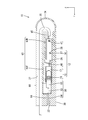
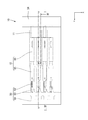
- FIG. 1 is a cross-sectional view showing a joint connector according to the first embodiment, and is a cross-sectional view taken along the line II in FIG.
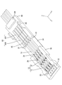
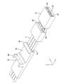
- FIG. 2 is a perspective view showing the lower housing, the hinge, and the upper cover.
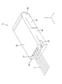
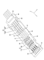
- FIG. 3 is a perspective view showing a joint connector.
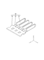
- FIG. 4 is a perspective view showing a bus bar.
- FIG. 5 is a sectional view taken along line VV in FIG.
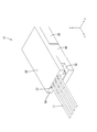
- FIG. 6 is a perspective view showing a state in which an electric wire is inserted through the upper cover.
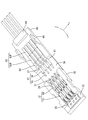
- FIG. 7 is a perspective view showing a state in which an electric wire is inserted through the terminal.
- FIG. 8 is a perspective view showing a state in which the electric wire and the terminal are electrically connected by moving the slide portion to the main locking position.
- FIG. 1 is a cross-sectional view showing a joint connector according to the first embodiment, and is a cross-sectional view taken along the line II in FIG.
- FIG. 2 is a perspective view
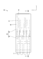
- FIG. 9 is a plan view showing a joint connector.
- FIG. 10 is a perspective view showing a joint connector according to the second embodiment.
- FIG. 11 is a plan view showing a state before the lower housing and the upper cover are assembled.
- FIG. 12 is a perspective view showing a lower housing according to the third embodiment.
- FIG. 13 is a perspective view showing a state before the lower housing and the upper cover are assembled.
- FIG. 14 is a plan view showing a joint connector.
- FIG. 15 is a sectional view taken along line XV-XV in FIG.
- the present disclosure is a joint connector for connecting a plurality of electric wires, the plurality of electric wires extending along the extending direction and a plurality of terminals connected to the front ends of the plurality of electric wires in the extending direction.
- a lower housing for accommodating the plurality of terminals, a bus bar disposed in the lower housing, and an upper cover assembled to the lower housing.
- the bus bar has a plurality of tabs, and the plurality of tabs are provided.
- Each of the terminals has a bus bar connection portion to which the plurality of tabs are connected, and an electric wire connection portion to which the plurality of electric wires are connected, respectively, and is led out from the lower housing to the rear in the extension direction.
- the plurality of electric wires have a bent portion that is folded forward in the extending direction, and the upper cover has an electric wire holding portion that holds the plurality of electric wires in a state of being folded forward in the extending direction. ..
- the upper cover preferably has an electric wire holding portion that presses the plurality of electric wires led out from the lower housing to the rear in the extending direction toward the lower housing.
- the plurality of electric wires are pressed toward the lower housing by the electric wire holding portion of the upper cover, it is suppressed that the force applied to the electric wires is transmitted before the electric wire pressing portion. As a result, the external force applied to the electric wire is suppressed from being transmitted to the terminal.
- the upper cover is connected to the lower housing via a hinge extending from the rear of the lower housing in the extending direction.
- the lower housing and upper cover are connected via hinges, the number of parts can be reduced. Further, since the hinge protects a plurality of electric wires, it is possible to prevent an external force from being applied to the electric wires.
- the upper cover has a terminal engaging portion that engages with the terminal from behind in the extending direction in a state of being assembled to the lower housing.
- the terminal engaging portion engages with the terminal from the rear in the extending direction, the terminal moves backward in the extending direction even if the external force applied to the electric wire crosses the bent portion and reaches the electric wire connecting portion. Is being suppressed. As a result, the terminals are firmly held by the lower housing and the upper cover.
- the inner surface of the upper cover is provided with a bus bar holding portion that sandwiches the bus bar between the lower housing and the lower housing in a state where the lower housing and the upper cover are assembled.
- the bus bar can be held by a simple operation of assembling the lower housing and upper cover.
- the electric wire holding portion is preferably formed in a hole shape through which the electric wire is inserted.
- the electric wire By inserting the electric wire into the hole-shaped electric wire holding portion, the electric wire can be reliably held along the extending direction. Further, at least the portion of the electric wire arranged in the electric wire holding portion can be protected from an external force.
- the electric wire connecting portion extends along the extending direction and is arranged outside the sandwiching portion and can move along the extending direction as well as a sandwiching portion that sandwiches one of the plurality of electric wires. It is preferable that the slide portion has a slide portion, and the slide portion has a pressurizing portion that pressurizes the sandwiched portion toward the electric wire in a state where one of the plurality of electric wires is sandwiched between the sandwiched portions. ..
- the mold required for crimping the barrel to the outer circumference of the electric wire becomes unnecessary, and the manufacturing cost of the joint connector can be reduced. ..
- Embodiment 1 of the present disclosure will be described with reference to FIGS. 1-9.
- the joint connector 10 according to this embodiment electrically connects a plurality of electric wires 11.
- the direction indicated by the arrow Z will be on the top
- the direction indicated by the arrow Y will be the front
- the direction indicated by the arrow X will be on the left.
- a plurality of the same members only some of the members may be coded and the codes of other members may be omitted.
- the joint connector 10 has a plurality of electric wires 11 extending in the front-rear direction (an example of an extension direction) and a plurality of terminals connected to the front ends of the plurality of electric wires 11. 12, a bus bar 50 connected to a plurality of terminals 12, a lower housing 30 in which the plurality of terminals 12 and the bus bar 50 are housed, and an upper cover 60 attached to the upper portion of the lower housing 30 at the rear. ..
- the plurality of electric wires 11 are arranged so as to extend in the front-rear direction (an example of the extending direction).
- the outer circumference of the core wire 13 of the electric wire 11 is surrounded by an insulating coating 14 made of an insulating synthetic resin.
- the core wire 13 according to the present embodiment is made of one metal wire.
- the core wire 13 may be a stranded wire obtained by twisting a plurality of fine metal wires.
- any metal such as copper, copper alloy, aluminum, and aluminum alloy can be appropriately selected as needed.
- the core wire 13 according to this embodiment is made of copper or a copper alloy.
- the lower housing 30 has a rectangular parallelepiped shape that is flat in the vertical direction.
- a material containing an insulating synthetic resin is formed by injection molding.
- a plurality of cavities 29 (four in the present embodiment) extending in the front-rear direction are formed side by side in the left-right direction.
- the cavity 29 is opened upward so that the terminal 12 is arranged in the cavity 29 from above.
- Cavities 29 adjacent to each other in the left-right direction are separated by a partition wall 31 extending in the front-rear direction.
- the partition wall 31 electrically insulates the terminals 12 arranged in each cavity 29.
- the cavity 29 opens forward at the front end portion of the lower housing 30.
- a bus bar mounting portion 32 formed so as to be flush with the bottom wall of the cavity 29 and extending in the left-right direction is formed.
- the bus bar 50 is mounted on the bus bar mounting portion 32 from above.
- FIG. 1 the upper portion of the lower housing 30 is covered by the upper cover 60 assembled from above.
- the upper cover 60 is formed by injection molding an insulating synthetic resin.
- a lock claw 66 extending in the vertical direction is formed on the side edge of the upper cover 60. The lock claw 66 elastically engages with the lock receiving portion 33 provided on the side wall of the lower housing 30, so that the lower housing 30 and the upper cover 60 can be integrally assembled.
- the hinge 34 has a thin plate shape and is formed to be bendable.
- the upper cover 60 has an upper wall 61.
- a plurality of (four in this embodiment) electric wire holding portions 37 for holding the electric wires 11 are provided side by side on the upper wall 61 of the upper cover 60 in the left-right direction.
- the electric wire holding portion 37 is formed in a hole shape that penetrates the upper wall of the upper cover 60 in the front-rear direction.
- the inner diameter of the electric wire holding portion 37 is set to be the same as or larger than the outer diameter of the insulating coating 14 of the electric wire 11. As a result, the electric wire 11 is inserted into the electric wire holding portion 37.
- the front end portion of the upper wall 61 of the upper cover 60 is located downward at a position corresponding to the cavity 29 of the lower housing 30.
- a protruding bus bar holding portion 64 is formed.
- the bus bar holding portion 64 sandwiches the bus bar 50 with the bus bar mounting portion 32 of the lower housing 30.
- a connecting portion 54 which will be described later, is sandwiched between the bus bar holding portion 64 and the bus bar mounting portion 32. As a result, the bus bar 50 is held by the lower housing 30 and the upper cover 60.
- the terminal engaging portion 63 of (1) extends in the front-rear direction.
- the terminal engaging portion 63 includes a front terminal engaging portion 63F located on the front side and a rear terminal engaging portion 63R located on the rear portion of the front terminal engaging portion 63F.
- the rear terminal engaging portion 63R projects downward from the front terminal engaging portion 63F.
- the upper wall 61 is provided with a wire holding portion 65 projecting downward behind the terminal engaging portion 63.
- the electric wire pressing portion 65 comes into contact with the electric wire 11 led out rearward from the rear end portion of the terminal 12 from above, and presses the electric wire 11 from above toward the lower housing 30.
- the electric wire holding portion 65 is formed so as to extend in the left-right direction, and even when the electric wire 11 led out rearward from the terminal 12 is arranged at a position deviated from the cavity 29, the electric wire is reliably formed. It is designed to hold down 11.
- the bus bar 50 is formed by pressing a metal plate material into a predetermined shape.
- the metal plate material any metal such as copper and copper alloy can be appropriately selected.
- the bus bar 50 has a plurality of (four in this embodiment) tabs 52 extending rearward, and a connecting portion 54 connecting the front end portions of the tabs 52 via a relay portion 53.
- the tab 52 has a flat plate shape in the left-right direction.
- the connecting portion 54 has a flat plate shape in the vertical direction.
- the relay portion 53 is formed so as to extend rearward from the connecting portion 54. The right edge of the connecting portion 54 is bent downward and is connected to the tab 52.
- the terminal 12 includes a metal terminal body 15 and a slide portion 16 that can slide relative to the terminal body 15.
- Terminal body 15 The terminal body 15 is formed into a predetermined shape by a known method such as pressing, cutting, casting, or the like.
- metal constituting the terminal body 15 any metal such as copper, copper alloy, aluminum, aluminum alloy, and stainless steel can be appropriately selected as needed.
- the terminal body 15 according to this embodiment is made of copper or a copper alloy.
- a plating layer may be formed on the surface of the terminal body 15.
- any metal such as tin, nickel, and silver can be appropriately selected as required.
- the terminal body 15 according to this embodiment is tin-plated.
- the terminal body 15 has a tubular portion 17 (an example of a bus bar connecting portion) into which a tab 52 can be inserted and an electric wire connecting portion 20 located behind the tubular portion 17 and connected to the electric wire 11.
- the electric wire connecting portion 20 includes an upper holding portion 18A and a lower holding portion 18B extending rearward.
- the tubular portion 17 has a square tubular shape extending in the front-rear direction.
- the front end of the tubular portion 17 is opened so that the tab 52 can be inserted.
- FIG. 1 shows a part of the elastic contact piece 19 provided on the tubular portion 17.
- an elastic contact piece 19 that is elastically deformable is arranged inside the tubular portion 17.
- the elastic contact piece 19 extends inward from the inner wall of the tubular portion 17.
- the tab 52 inserted into the tubular portion 17 presses the elastic contact piece 19 to elastically deform it.
- the tab 52 is sandwiched between the inner wall of the tubular portion 17 and the elastic contact piece 19 due to the elastic force of the elastically deformed elastic contact piece 19. As a result, the tab 52 and the terminal 12 are electrically connected.
- a square tubular electric wire connecting portion 20 is provided behind the tubular portion 17.
- An upper holding portion 18A (an example of a holding portion) is provided at the rear end of the upper wall of the electric wire connecting portion 20 so as to extend rearward
- a lower holding portion is provided at the rear end of the lower wall of the electric wire connecting portion 20.
- 18B (an example of a holding portion) is provided so as to extend rearward.
- the upper holding portion 18A and the lower holding portion 18B have an elongated shape extending back and forth.
- the upper holding portion 18A and the lower holding portion 18B are formed to have substantially the same length dimension in the front-rear direction.
- an upper holding protrusion 23A protruding downward is provided at a position in front of the rear end portion.
- a lower holding protrusion 23B that projects upward is provided at the rear end of the upper surface of the lower holding portion 18B.
- the lower holding protrusion 23B and the upper holding protrusion 23A are provided at positions shifted in the front-rear direction.
- the core wire 13 and the terminal body 15 are electrically connected by contacting the metal surface with the upper holding portion 18A and the lower holding portion 18B.
- the slide portion 16 has a square tubular shape extending in the front-rear direction.
- the slide portion 16 is formed by a known method such as cutting, casting, or pressing, if necessary.
- any metal such as copper, copper alloy, aluminum, aluminum alloy, and stainless steel can be appropriately selected as needed.
- the slide portion 16 according to the present embodiment is not particularly limited, but is made of stainless steel.
- a plating layer may be formed on the surface of the slide portion 16.
- any metal such as tin, nickel, and silver can be appropriately selected as required.
- the cross section of the inner shape of the slide portion 16 is the same as or slightly larger than the cross section of the outer shape of the region of the terminal body 15 where the upper holding portion 18A and the lower holding portion 18B are provided. As a result, the slide portion 16 is arranged outside the region of the terminal body 15 where the upper holding portion 18A and the lower holding portion 18B are provided.
- an upper pressurizing portion 25A (an example of a pressurizing portion) projecting downward is provided on the lower surface of the upper wall of the slide portion 16.
- a lower pressurizing portion 25B (an example of the pressurizing portion) projecting upward is provided.
- a temporary locking receiving portion 26 is opened on the side wall of the slide portion 16 at a position closer to the front end portion in the front-rear direction. Further, on the side wall of the slide portion 16, the main locking receiving portion 27 is opened at a position behind the temporary locking receiving portion 26.
- the temporary locking receiving portion 26 and the main locking receiving portion 27 can be elastically locked with the locking projection 28 provided on the side wall of the terminal body 15.
- the state in which the locking projection 28 of the terminal body 15 and the temporary locking receiving portion 26 of the slide portion 16 are locked is a state in which the sliding portion 16 is held at the temporary locking position with respect to the terminal main body 15. ..
- the upper pressurizing portion 25A and the lower pressurizing portion 25B of the slide portion 16 are separated rearward from the rear end edges of the upper holding portion 18A and the lower holding portion 18B of the terminal body 15. Further, in this state, the distance between the upper holding portion 18A and the lower holding portion 18B is set to be larger than the diameter of the core wire 13.
- the slide portion 16 is locked at the main locking position with respect to the terminal main body 15. There is. As shown in FIG. 1, in this state, the upper pressurizing portion 25A of the slide portion 16 is in contact with the upper holding portion 18A from above the upper holding portion 18A. Further, the lower pressurizing portion 25B of the slide portion 16 is in contact with the lower holding portion 18B from below the lower holding portion 18B.
- the slide portion 16 is fitted into the region of the terminal body 15 where the upper holding portion 18A and the lower holding portion 18B are provided, and is fitted into the above-mentioned temporary locking position and the main locking. It can be slid to and from the position.
- the upper holding portion 18A is pressed by the upper pressing portion 25A from above to press the upper holding portion 18A. Is designed to deform downward. Further, the lower pressing portion 25B presses the lower holding portion 18B from below, so that the lower holding portion 18B is deformed upward. As a result, the core wire 13 is arranged in the space between the upper holding portion 18A and the lower holding portion 18B in a state of being extended in the front-rear direction (extending direction), and the slide portion 16 is arranged with respect to the terminal body 15.
- the core wire 13 is sandwiched from the vertical direction by the elastically deformed upper holding portion 18A and the lower holding portion 18B. That is, the upper holding portion 18A comes into contact with the core wire 13 from above by being pressed downward by the upper pressing portion 25A, and the lower holding portion 18B is pressed upward by the lower pressing portion 25B to bring the core wire 13 into contact. It comes in contact with the cable from below.
- the upper holding protrusion 23A of the upper holding portion 18A presses the core wire 13 from above, and the lower side.
- the lower holding protrusion 23B of the holding portion 18B presses the core wire 13 from below.
- the core wire 13 is pressed from above by the upper holding protrusion 23A and is pressed from below by the lower holding protrusion 23B arranged at a position deviated from the upper holding protrusion 23A in the front-rear direction. Therefore, it is held in a bent state in the vertical direction (an example of a direction intersecting the extending direction).
- the core wire 13 and the terminal 12 are also electrically connected by the upper holding protrusion 23A and the lower holding protrusion 23B.
- a jig contact portion 46 projecting upward from the upper wall is provided at the front end portion of the slide portion 16.
- a jig comes into contact with the jig contact portion 46 from the rear, and the slide portion 16 is pushed forward by this jig, so that the slide portion 16 can move forward.
- a pair of invitation portions 47 projecting inward of the slide portion 16 are provided on the left and right side walls.
- the invitation portion 47 is formed narrower from the rear to the front.
- the front terminal engaging portion 63F engages with the cylinder portion 17 from above, and the cylinder portion 17 moves upward. It suppresses movement.
- the rear terminal engaging portion 63R engages with the slide portion 16 from above to prevent the slide portion 16 from moving upward.
- the front end portion of the rear terminal engaging portion 63R engages the jig contact portion of the slide portion 16 from the rear to prevent the slide portion 16 and the terminal body 15 from moving rearward.
- the front end portion of the electric wire holding portion 65 is engaged with the rear end portion of the slide portion 16 from the rear to prevent the slide portion 16 and the terminal body 15 from moving rearward.
- the terminal body 15 and the slide portion 16 are formed by a known method.
- the slide portion 16 is assembled from the rear to the terminal body 15.
- the front end edge of the slide portion 16 comes into contact with the locking projection 28 of the terminal body 15 from the rear, and the side wall of the slide portion 16 is expanded and deformed.
- the slide portion 16 is further pushed forward, the side wall of the slide portion 16 is restored and deformed, and the temporary locking receiving portion 26 of the slide portion 16 is locked to the locking projection 28 of the terminal body 15.
- the slide portion 16 is held at the temporarily locked position with respect to the terminal body 15.
- the terminal 12 is obtained.
- the lower housing 30 and the upper cover 60 are integrally formed via the hinge 34. As shown in FIG. 2, the lower housing 30 and the upper cover 60 are arranged so as to be arranged in the front-rear direction via the hinge 34.
- the tab 52 of the bus bar 50 is inserted into the tubular portion 17 from the front.
- the tab 52 and the elastic piece come into contact with each other, the tab 52 and the terminal 12 are electrically connected.
- the plurality of terminals 12 are electrically connected via the bus bar 50.
- the terminal 12 connected to the bus bar 50 is inserted into the cavity 29 of the lower housing 30 from above.
- the core wire 13 of the electric wire 11 is exposed by peeling the insulating coating 14 by a known method.
- the electric wire 11 is inserted into the electric wire holding portion 37 of the upper cover 60 from the rear with the core wire 13 on the front side.
- the cavity 29 is located in front of each electric wire holding portion 37.
- the electric wire 11 inserted through the electric wire holding portion 37 enters each cavity 29.
- the jig (not shown) is brought into contact with the jig contact portion 46 from the rear, and the slide portion 16 is slid forward.
- the slide portion 16 is moved forward relative to the terminal body 15.
- the locking projection 28 of the terminal body 15 and the temporary locking receiving portion 26 of the slide portion 16 are disengaged, and the side wall of the slide portion 16 rides on the locking projection 28 to expand and deform.
- the upper pressurizing portion 25A of the slide portion 16 abuts on the upper holding portion 18A of the terminal body 15 from above and presses downward.
- the lower pressurizing portion 25B of the slide portion 16 abuts on the lower holding portion 18B of the terminal body 15 from below and presses it upward.
- the core wire 13 is sandwiched between the upper sandwiching portion 18A and the lower sandwiching portion 18B from above and below (see FIG. 1).
- the core wire 13 is sandwiched between the lower surface of the upper holding portion 18A and the upper surface of the lower holding portion 18B, the oxide film formed on the surface of the core wire 13 is peeled off, and the core wire 13 is removed. The constituent metal surface is exposed.
- the electric wire 11 and the terminal 12 are electrically connected by contacting the metal surface with the upper holding portion 18A and the lower holding portion 18B. As a result, the plurality of electric wires 11 are electrically connected via the terminal 12 and the bus bar 50 (see FIG. 9).
- the core wire 13 In a state where the core wire 13 is sandwiched between the upper holding portion 18A and the lower holding portion 18B from above and below, the core wire 13 has the upper holding protrusion 23A of the upper holding portion 18A and the lower holding protrusion 18B of the lower holding portion 18B.
- the cable By being sandwiched between the 23B and 23B, the cable is held in a state of being extended in the front-rear direction and in a state of being bent in the vertical direction.
- the core wire 13 can be firmly held, so that when a tensile force acts on the electric wire 11, the holding force between the electric wire 11 and the terminal 12 can be increased.
- the upper cover 60 is assembled to the lower housing 30 from above the lower housing 30 while bending the hinge 34 into a C shape when viewed from the side.
- the lower housing 30 and the upper cover 60 are integrally assembled by elastically engaging the lock claw 66 of the upper cover 60 and the lock receiving portion 33 of the lower housing 30.
- the electric wire 11 led out to the rear of the lower housing 30 bends from above to the front and extends forward.
- a portion of the electric wire 11 that is bent in a C shape behind the lower housing 30 and the upper cover 60 is a bent portion 35.
- the electric wire 11 is held in the electric wire holding portion 37 of the upper cover 60 in a state of extending forward. This completes the joint connector 10.
- this embodiment there are 10 joint connectors for connecting a plurality of electric wires 11, a plurality of electric wires 11 extending in the front-rear direction, a plurality of terminals 12 connected to the front ends of the plurality of electric wires 11, and a plurality of terminals 12, respectively.
- a lower housing 30 accommodating a plurality of terminals 12, a bus bar 50 arranged in the lower housing 30, and an upper cover 60 assembled to the lower housing 30 are provided, and the bus bar 50 has a plurality of tabs 52 and has a plurality of tabs 52.
- Each of the terminals 12 has a tubular portion 17 into which a plurality of tabs 52 are inserted, and an electric wire connecting portion 20 to which the plurality of electric wires 11 are connected, respectively, and a plurality of terminals 12 are led out rearward from the lower housing 30.
- the electric wire 11 of the above is folded forward, and the upper cover 60 has an electric wire holding portion 37 for holding the plurality of electric wires 11 in a state of being folded forward.
- the upper cover has an electric wire holding portion 65 that presses a plurality of electric wires 11 led out rearward from the lower housing toward the lower housing 30.
- the force applied to the electric wires 11 may be transmitted before the electric wire pressing portions 65. It is suppressed. As a result, the external force applied to the electric wire 11 is suppressed from being transmitted to the terminal 12.
- the upper cover 60 is connected to the lower housing 30 via a hinge 34 extending from the rear of the lower housing 30.
- the hinge 34 Since the lower housing 30 and the upper cover 60 are connected via the hinge 34, the number of parts can be reduced. Further, since the hinge 34 is located outside the plurality of electric wires 11, the plurality of electric wires 11 are protected, so that external force is suppressed from being applied to the electric wires 11 themselves.
- the upper cover 60 has a terminal engaging portion 63 that engages with the terminal 12 from the rear in a state of being assembled to the lower housing 30.
- the terminal engaging portion 63 is engaged with the terminal 12 from the rear in the extending direction, even if the external force applied to the electric wire 11 exceeds the bent portion 35 and reaches the electric wire connecting portion 20, the terminal 12 remains. It is designed to prevent backward movement. As a result, the terminal 12 is firmly held by the lower housing 30 and the upper cover 60.
- a bus bar holding portion 64 for sandwiching the bus bar 50 between the lower housing 39 and the lower housing 39 is provided on the lower surface of the upper cover 60 in a state where the lower housing 39 and the upper cover 60 are assembled. ..
- the bus bar 50 can be held by a simple operation of assembling the lower housing 39 and the upper cover 60.
- the electric wire holding portion 37 is formed in a hole shape through which the electric wire 11 is inserted.
- the electric wire 11 By inserting the electric wire 11 through the electric wire holding portion 37 having a hole shape, the electric wire 11 can be reliably held along the front-rear direction. Further, at least the portion of the electric wire 11 arranged in the electric wire holding portion 37 can be protected from an external force.
- the electric wire connecting portion 20 extends along the front-rear direction and sandwiches one of the plurality of electric wires 11 with the upper sandwiching portion 18A and the lower sandwiching portion 18B, and the upper sandwiching portion 18A and the lower sandwiching portion 18A.
- the slide portion 16 has a slide portion 16 arranged on the outside of the portion 18B and movable in the front-rear direction, and the slide portion 16 has one of a plurality of electric wires 11 on the upper holding portion 18A and the lower holding portion 18B. It has an upper pressing portion 25A and a lower pressing portion 25B that pressurize the upper holding portion 18A and the lower holding portion 18B toward the electric wire 11 in a sandwiched state.
- the barrel is crimped to the outer circumference of the electric wire 11.
- the mold required for this is not required, and the manufacturing cost of the joint connector 10 can be reduced.
- Embodiment 2 of the present disclosure will be described with reference to FIGS. 10 to 11.
- the joint connector 70 according to the present embodiment is not provided with a hinge for connecting the lower housing 30 and the upper cover 60, and the lower housing 30 and the upper cover 60 are configured as separate parts.
- the electric wire 11 is inside the electric wire holding portion 37 of the upper cover 60 in a state where the lower housing 30 and the upper cover 60 are arranged in the front-rear direction by a jig (not shown). It is inserted into the terminal 12 housed in the cavity 29 of the lower housing 30.
- the joint connector 80 includes a lower housing 81, an upper cover 82 assembled to the lower housing 81 from above, a bus bar 83 arranged in the lower housing 81, and a terminal 84 arranged in the lower housing 81. To be equipped with.
- the lower housing 81 has a rectangular parallelepiped shape that is flat in the vertical direction.
- a plurality of cavities 85 (four in the present embodiment) penetrating in the front-rear direction are formed side by side in the left-right direction.
- a notch 86 notched upward is provided near the center position in the front-rear direction of the lower housing 81. The cavity 85 is exposed upward from the notch 86.
- a bus bar insertion hole 87 into which the bus bar 83 is inserted from the front is formed at the front end of the lower housing 81 so as to extend in the left-right direction.
- the height dimension of the bus bar insertion hole 87 in the vertical direction is formed to be the same as or slightly larger than the thickness dimension of the bus bar 83.
- a plurality of (four in this embodiment) die-cutting holes 88 are formed above the bus bar insertion holes 87 so as to extend in the front-rear direction.
- a lance 89 that elastically engages with the terminal 84 to hold the terminal 84 in the cavity 85 is formed inside each die-cutting hole 88.
- the lance 89 has a shape extending forward from the upper wall of the cavity 85. The front end portion of the lance 89, the terminal 84, and the upper wall of the tubular portion 90 are intertwined with each other.
- the terminal 84 has a tubular portion 90 into which a plurality of tabs 91 provided on the bus bar 83 are inserted, and an electric wire connecting portion 92 provided behind the tubular portion 90, respectively.
- the electric wire connecting portion 92 has a so-called barrel shape, and electrically connects the electric wire 11 and the terminal 84 by crimping to the outer circumference of the electric wire 11.
- a plurality of (four in this embodiment) electric wire holding portions 93 are formed on the upper cover 82 so as to extend in the front-rear direction.
- the electric wire holding portion 93 is formed in a hole shape that penetrates the upper cover 82 in the front-rear direction.
- the upper cover 82 is formed with elastically deformable lock claws 94 protruding in the vertical direction in the vicinity of the central position in the front-rear direction, corresponding to the notch 86 of the lower housing 81.
- the lower housing 81 and the upper cover 82 are integrally assembled by the lock claws 94 being arranged on the left and right sides of the notch 86 of the lower housing 81 and elastically engaging with the lower end edge of the cavity 85. It has become like.
- the upper cover 82 projects downward at a position corresponding to the notch 86 of the lower housing 81.
- a terminal engaging portion 95 is formed.
- the terminal engaging portion 95 enters the inside of the cavity 85 through the notch 86 of the lower housing 81 and engages with the rear end portion of the tubular portion 90 of the terminal 84 from the rear. As a result, the terminal 84 is held in the cavity 85 to prevent it from coming off rearward.
- the terminal 84 can be held in the cavity 85 in a retaining state, so that the terminal 84 can be firmly held in the cavity 85.
- the electric wire holding portion may have a groove shape.
- the wire holding portion may be omitted.
- the joint connector may be configured to connect two, three, or five or more electric wires.
- the terminal may be configured to have one or three or more sandwiching portions.
Landscapes
- Connector Housings Or Holding Contact Members (AREA)
- Details Of Connecting Devices For Male And Female Coupling (AREA)
Abstract
This joint connector 10 for connecting a plurality of electric wires 11 is provided with: the plurality of electric wires 11 extending in an extending direction; a plurality of terminals 12 connected to respective front end sections in the extending direction of the plurality of electric wires 11; a lower housing 30 for accommodating the plurality of terminals 12; a busbar 50 installed in the lower housing 30; and an upper cover 60 assembled to the lower housing 30, wherein the busbar 50 has a plurality of taps 52, the plurality of terminals 12 each have a tubular part 17 into which each of the plurality of tabs 52 is inserted, and an electric wire connection part 20 to which each of the plurality of electric wires 11 is connected, the plurality of electric wires 11 drawn from the lower housing 30 to the rear side in the extension direction has a bent part 35 folded back to the front side in the extension direction, and the upper cover 60 has an electric wire holding part 37 in which the plurality of electric wires 11 are held in a state of folded back to the front side in the extension direction.
Description
本開示は、ジョイントコネクタに関する。
This disclosure relates to joint connectors.
ジョイントコネクタとして特開平10-261471号公報に記載のものが知られている。このジョイントコネクタは、ハウジングの各端子収容室の端子挿入口にブスバー付きリテーナのリテーナ本体を嵌合自在に設け、このリテーナ本体に各端子収容室の端子挿入口に設けられた係合部に係止される係止部を設けると共に、ブスバー付きリテーナのブスバーの端子をジョイント端子の係止部に係止自在にしてある。また、ブスバー付きリテーナと同形のリテーナのリテーナ本体を各ハウジングの各端子収容室の端子挿入口に嵌合自在に設けてある。
A joint connector described in JP-A-10-261471 is known. In this joint connector, the retainer body of the retainer with a bus bar is provided in the terminal insertion port of each terminal storage chamber of the housing so as to be able to be fitted, and the retainer body is engaged with the engaging portion provided in the terminal insertion port of each terminal accommodation chamber. A locking portion to be stopped is provided, and the terminal of the bus bar of the retainer with a bus bar is freely locked to the locking portion of the joint terminal. Further, the retainer main body of the retainer having the same shape as the retainer with a bus bar is provided so as to be freely fitted to the terminal insertion port of each terminal accommodating chamber of each housing.
近時、車両に搭載されるジョイントコネクタについては小型化が求められている。ジョイントコネクタのハウジングを小型化することに伴い、端子を係止する部品(例えばリテーナ)も小型化することが考えられる。すると、端子を係止する部品の強度が低下する場合が想定される。これにより端子がハウジングに強固に係止されなくなる結果、電線を介して端子に伝達された外力によって端子とハウジングが、がたつくことが懸念される。また、端子を小型化すると端子自体の強度も低下するので、電線を介して加えられる外力によって端子自体が不具合を生じるおそれもある。
Recently, there is a demand for miniaturization of joint connectors mounted on vehicles. As the housing of the joint connector becomes smaller, it is conceivable that the parts that lock the terminals (for example, retainers) also become smaller. Then, it is assumed that the strength of the component that locks the terminal decreases. As a result, the terminals are not firmly locked to the housing, and as a result, there is a concern that the terminals and the housing may rattle due to the external force transmitted to the terminals via the electric wires. Further, when the terminal is miniaturized, the strength of the terminal itself is also lowered, so that the terminal itself may be defective due to the external force applied via the electric wire.
本開示は上記のような事情に基づいて完成されたものであって、電線からの外力が端子に伝達されることを抑制できるジョイントコネクタを提供することを目的とする。
The present disclosure has been completed based on the above circumstances, and an object of the present disclosure is to provide a joint connector capable of suppressing transmission of an external force from an electric wire to a terminal.
本開示は、複数の電線を接続するジョイントコネクタであって、延び方向に沿って延びる前記複数の電線と、前記複数の電線の延び方向の前方端部にそれぞれ接続される複数の端子と、前記複数の端子を収容するロアハウジングと、前記ロアハウジングに配設されるバスバーと、前記ロアハウジングに組み付けられるアッパーカバーと、を備え、前記バスバーは複数のタブを有し、前記複数の端子のそれぞれは、前記複数のタブがそれぞれ接続されるバスバー接続部と、前記複数の電線がそれぞれ接続される電線接続部と、を有し、前記ロアハウジングから前記延び方向の後方に導出された前記複数の電線は、前記延び方向の前方へ折り返された曲がり部を有し、前記アッパーカバーは、前記複数の電線が前記延び方向の前方に折り返された状態で保持される電線保持部を有する。
The present disclosure is a joint connector for connecting a plurality of electric wires, the plurality of electric wires extending along an extension direction, a plurality of terminals connected to front ends of the plurality of electric wires in the extension direction, and the above-mentioned. A lower housing for accommodating a plurality of terminals, a bus bar arranged in the lower housing, and an upper cover assembled to the lower housing are provided, and the bus bar has a plurality of tabs, and each of the plurality of terminals is provided. Has a bus bar connection portion to which the plurality of tabs are connected, and an electric wire connection portion to which the plurality of electric wires are connected, respectively, and the plurality of electric wires are led out from the lower housing to the rear in the extending direction. The electric wire has a bent portion that is folded forward in the extending direction, and the upper cover has an electric wire holding portion that holds the plurality of electric wires folded forward in the extending direction.
本開示によれば、電線を介して端子に外力が伝達されることを抑制できる。
According to the present disclosure, it is possible to suppress the transmission of an external force to the terminal via the electric wire.
[本開示の実施形態の説明]
最初に本開示の実施態様が列挙されて説明される。 [Explanation of Embodiments of the present disclosure]
First, embodiments of the present disclosure will be listed and described.
最初に本開示の実施態様が列挙されて説明される。 [Explanation of Embodiments of the present disclosure]
First, embodiments of the present disclosure will be listed and described.
(1)本開示は、複数の電線を接続するジョイントコネクタであって、延び方向に沿って延びる前記複数の電線と、前記複数の電線の延び方向の前方端部にそれぞれ接続される複数の端子と、前記複数の端子を収容するロアハウジングと、前記ロアハウジングに配設されるバスバーと、前記ロアハウジングに組み付けられるアッパーカバーと、を備え、前記バスバーは複数のタブを有し、前記複数の端子のそれぞれは、前記複数のタブがそれぞれ接続されるバスバー接続部と、前記複数の電線がそれぞれ接続される電線接続部と、を有し、前記ロアハウジングから前記延び方向の後方に導出された前記複数の電線は、前記延び方向の前方へ折り返された曲がり部を有し、前記アッパーカバーは、前記複数の電線が前記延び方向の前方に折り返された状態で保持される電線保持部を有する。
(1) The present disclosure is a joint connector for connecting a plurality of electric wires, the plurality of electric wires extending along the extending direction and a plurality of terminals connected to the front ends of the plurality of electric wires in the extending direction. A lower housing for accommodating the plurality of terminals, a bus bar disposed in the lower housing, and an upper cover assembled to the lower housing. The bus bar has a plurality of tabs, and the plurality of tabs are provided. Each of the terminals has a bus bar connection portion to which the plurality of tabs are connected, and an electric wire connection portion to which the plurality of electric wires are connected, respectively, and is led out from the lower housing to the rear in the extension direction. The plurality of electric wires have a bent portion that is folded forward in the extending direction, and the upper cover has an electric wire holding portion that holds the plurality of electric wires in a state of being folded forward in the extending direction. ..
延び方向の前方へ延びる複数の電線に外力が加えられると、この外力は延び方向の後方へと各電線に伝達される。各電線の延びる方向は、曲がり部において、延び方向について反転されている。これにより、各電線に伝達された力は、曲がり部において吸収されるので、電線に加えられた力が端子にまで伝えられることが抑制される。
When an external force is applied to a plurality of electric wires extending forward in the extending direction, this external force is transmitted to each electric wire backward in the extending direction. The extending direction of each electric wire is reversed with respect to the extending direction at the bent portion. As a result, the force transmitted to each electric wire is absorbed at the bent portion, so that the force applied to the electric wire is suppressed from being transmitted to the terminal.
(2)前記アッパーカバーは、前記ロアハウジングから前記延び方向の後方に導出された前記複数の電線を、前記ロアハウジングに向かって押さえる電線押え部を有することが好ましい。
(2) The upper cover preferably has an electric wire holding portion that presses the plurality of electric wires led out from the lower housing to the rear in the extending direction toward the lower housing.
複数の電線は、アッパーカバーの電線押え部によって、ロアハウジングに向かって押さえられているので、電線に加えられた力は、電線押え部よりも先に伝達されることが抑制される。これにより、電線に加えられた外力が端子にまで伝達されることが抑制される。
Since the plurality of electric wires are pressed toward the lower housing by the electric wire holding portion of the upper cover, it is suppressed that the force applied to the electric wires is transmitted before the electric wire pressing portion. As a result, the external force applied to the electric wire is suppressed from being transmitted to the terminal.
(3)前記延び方向について前記ロアハウジングの後方から延びたヒンジを介して、前記アッパーカバーが前記ロアハウジングと連結されていることが好ましい。
(3) It is preferable that the upper cover is connected to the lower housing via a hinge extending from the rear of the lower housing in the extending direction.
ロアハウジングとアッパーカバーとがヒンジを介して連結されているので、部品点数を削減することができる。また、ヒンジによって複数の電線が保護されるので、電線に外力が加えられることが抑制される。
Since the lower housing and upper cover are connected via hinges, the number of parts can be reduced. Further, since the hinge protects a plurality of electric wires, it is possible to prevent an external force from being applied to the electric wires.
(4)前記アッパーカバーは、前記ロアハウジングに組み付けられた状態で、前記延び方向の後方から前記端子と係合する端子係合部を有することが好ましい。
(4) It is preferable that the upper cover has a terminal engaging portion that engages with the terminal from behind in the extending direction in a state of being assembled to the lower housing.
端子係合部が、延び方向の後方から端子に係合しているので、電線に加えられた外力が曲がり部を越えて、電線接続部まで到達したとしても、端子が延び方向の後方に移動することが抑制されるようになっている。これにより、端子が、ロアハウジングおよびアッパーカバーに強固に保持されるようになっている。
Since the terminal engaging portion engages with the terminal from the rear in the extending direction, the terminal moves backward in the extending direction even if the external force applied to the electric wire crosses the bent portion and reaches the electric wire connecting portion. Is being suppressed. As a result, the terminals are firmly held by the lower housing and the upper cover.
(5)前記アッパーカバーの内面には、前記ロアハウジングと前記アッパーカバーとが組み付けられた状態で、前記ロアハウジングとの間で前記バスバーを挟むバスバー保持部が設けられていることが好ましい。
(5) It is preferable that the inner surface of the upper cover is provided with a bus bar holding portion that sandwiches the bus bar between the lower housing and the lower housing in a state where the lower housing and the upper cover are assembled.
ロアハウジングとアッパーカバーとを組み付けるという簡易な操作によりバスバーを保持できる。
The bus bar can be held by a simple operation of assembling the lower housing and upper cover.
(6)前記電線保持部は、前記電線を挿通させる孔状に形成されていることが好ましい。
(6) The electric wire holding portion is preferably formed in a hole shape through which the electric wire is inserted.
孔状をなす電線保持部に電線が挿通されることにより、電線を延び方向に沿って確実に保持することができる。また、電線のうち、少なくとも電線保持部内に配された部分を外力から保護することができる。
By inserting the electric wire into the hole-shaped electric wire holding portion, the electric wire can be reliably held along the extending direction. Further, at least the portion of the electric wire arranged in the electric wire holding portion can be protected from an external force.
(7)前記電線接続部は、前記延び方向に沿って延びるとともに前記複数の電線の1本を挟持する挟持部と、前記挟持部の外側に配されるとともに前記延び方向に沿って移動可能なスライド部と、を有し、前記スライド部は、前記挟持部に前記複数の電線の1本が挟まれた状態で、前記挟持部を前記電線に向けて加圧する加圧部を有することが好ましい。
(7) The electric wire connecting portion extends along the extending direction and is arranged outside the sandwiching portion and can move along the extending direction as well as a sandwiching portion that sandwiches one of the plurality of electric wires. It is preferable that the slide portion has a slide portion, and the slide portion has a pressurizing portion that pressurizes the sandwiched portion toward the electric wire in a state where one of the plurality of electric wires is sandwiched between the sandwiched portions. ..
挟持部が押圧部に押圧されることによって電線と端子とが接続されているので、電線の外周にバレルを圧着する際に必要とされる金型が不要となり、ジョイントコネクタの製造コストを低減できる。
Since the electric wire and the terminal are connected by pressing the holding portion against the pressing portion, the mold required for crimping the barrel to the outer circumference of the electric wire becomes unnecessary, and the manufacturing cost of the joint connector can be reduced. ..
[本開示の実施形態の詳細]
以下に、本開示の実施形態が説明される。本発明はこれらの例示に限定されるものではなく、特許請求の範囲によって示され、特許請求の範囲と均等の意味および範囲内での全ての変更が含まれることが意図される。 [Details of Embodiments of the present disclosure]
The embodiments of the present disclosure will be described below. The present invention is not limited to these examples, and is indicated by the scope of claims, and is intended to include all modifications within the meaning and scope equivalent to the scope of claims.
<実施形態1>
本開示の実施形態1が図1から図9を参照しつつ説明される。本実施形態にかかるジョイントコネクタ10は、複数の電線11を電気的に接続する。以下の説明では、矢線Zの示す向きを上とし、矢線Yの示す向きを前とし、矢線Xの示す向きを左として説明する。なお、複数の同一部材については、一部の部材にのみ符号を付し、他の部材の符号を省略する場合がある。 <Embodiment 1>
Embodiment 1 of the present disclosure will be described with reference to FIGS. 1-9. The joint connector 10 according to this embodiment electrically connects a plurality of electric wires 11. In the following description, the direction indicated by the arrow Z will be on the top, the direction indicated by the arrow Y will be the front, and the direction indicated by the arrow X will be on the left. Regarding a plurality of the same members, only some of the members may be coded and the codes of other members may be omitted.
本開示の実施形態1が図1から図9を参照しつつ説明される。本実施形態にかかるジョイントコネクタ10は、複数の電線11を電気的に接続する。以下の説明では、矢線Zの示す向きを上とし、矢線Yの示す向きを前とし、矢線Xの示す向きを左として説明する。なお、複数の同一部材については、一部の部材にのみ符号を付し、他の部材の符号を省略する場合がある。 <
図1に示されるように、本実施形態にかかるジョイントコネクタ10は、前後方向(延び方向の一例)に延びる複数の電線11と、複数の電線11の前方端部にそれぞれ接続される複数の端子12と、複数の端子12に接続されるバスバー50と、複数の端子12およびバスバー50が内部に収容されるロアハウジング30と、ロアハウジング30の上部に後部に取り付けられるアッパーカバー60と、を備える。
As shown in FIG. 1, the joint connector 10 according to the present embodiment has a plurality of electric wires 11 extending in the front-rear direction (an example of an extension direction) and a plurality of terminals connected to the front ends of the plurality of electric wires 11. 12, a bus bar 50 connected to a plurality of terminals 12, a lower housing 30 in which the plurality of terminals 12 and the bus bar 50 are housed, and an upper cover 60 attached to the upper portion of the lower housing 30 at the rear. ..
[電線11]
図1に示されるように、複数の電線11は、前後方向(延び方向の一例)に延びて配されている。電線11は、芯線13の外周を絶縁性の合成樹脂からなる絶縁被覆14で包囲されている。本実施形態にかかる芯線13は、1本の金属線からなる。なお、芯線13は複数の金属細線が撚り合わされてなる撚線であってもよい。芯線13を構成する金属は、銅、銅合金、アルミニウム、アルミニウム合金等、必要に応じて任意の金属を適宜に選択できる。本実施形態にかかる芯線13は銅、または銅合金からなる。 [Electric wire 11]
As shown in FIG. 1, the plurality ofelectric wires 11 are arranged so as to extend in the front-rear direction (an example of the extending direction). The outer circumference of the core wire 13 of the electric wire 11 is surrounded by an insulating coating 14 made of an insulating synthetic resin. The core wire 13 according to the present embodiment is made of one metal wire. The core wire 13 may be a stranded wire obtained by twisting a plurality of fine metal wires. As the metal constituting the core wire 13, any metal such as copper, copper alloy, aluminum, and aluminum alloy can be appropriately selected as needed. The core wire 13 according to this embodiment is made of copper or a copper alloy.
図1に示されるように、複数の電線11は、前後方向(延び方向の一例)に延びて配されている。電線11は、芯線13の外周を絶縁性の合成樹脂からなる絶縁被覆14で包囲されている。本実施形態にかかる芯線13は、1本の金属線からなる。なお、芯線13は複数の金属細線が撚り合わされてなる撚線であってもよい。芯線13を構成する金属は、銅、銅合金、アルミニウム、アルミニウム合金等、必要に応じて任意の金属を適宜に選択できる。本実施形態にかかる芯線13は銅、または銅合金からなる。 [Electric wire 11]
As shown in FIG. 1, the plurality of
[ロアハウジング30]
図2に示すように、ロアハウジング30は、上下に扁平な直方体形状をなしている。絶縁性の合成樹脂を含む材料が射出成型されて形成される。ロアハウジング30には、前後に延びる複数(本実施形態では4つ)のキャビティ29が、左右方向に並んで形成されている。キャビティ29は上方に開口されており、端子12がキャビティ29内に上方から配置されるようになっている。左右方向に隣り合うキャビティ29は前後方向に延びる隔壁31によって隔てられている。この隔壁31により、各キャビティ29内に配置された端子12が電気的に絶縁されている。 [Lower housing 30]
As shown in FIG. 2, thelower housing 30 has a rectangular parallelepiped shape that is flat in the vertical direction. A material containing an insulating synthetic resin is formed by injection molding. In the lower housing 30, a plurality of cavities 29 (four in the present embodiment) extending in the front-rear direction are formed side by side in the left-right direction. The cavity 29 is opened upward so that the terminal 12 is arranged in the cavity 29 from above. Cavities 29 adjacent to each other in the left-right direction are separated by a partition wall 31 extending in the front-rear direction. The partition wall 31 electrically insulates the terminals 12 arranged in each cavity 29.
図2に示すように、ロアハウジング30は、上下に扁平な直方体形状をなしている。絶縁性の合成樹脂を含む材料が射出成型されて形成される。ロアハウジング30には、前後に延びる複数(本実施形態では4つ)のキャビティ29が、左右方向に並んで形成されている。キャビティ29は上方に開口されており、端子12がキャビティ29内に上方から配置されるようになっている。左右方向に隣り合うキャビティ29は前後方向に延びる隔壁31によって隔てられている。この隔壁31により、各キャビティ29内に配置された端子12が電気的に絶縁されている。 [Lower housing 30]
As shown in FIG. 2, the
図2に示されるように、キャビティ29はロアハウジング30の前端部分において前方に開口している。ロアハウジング30の前端部には、キャビティ29の底壁と面一であると共に左右方向に延びて形成されたバスバー載置部32が形成されている。バスバー載置部32に、上方からバスバー50が載置されるようになっている。
As shown in FIG. 2, the cavity 29 opens forward at the front end portion of the lower housing 30. At the front end of the lower housing 30, a bus bar mounting portion 32 formed so as to be flush with the bottom wall of the cavity 29 and extending in the left-right direction is formed. The bus bar 50 is mounted on the bus bar mounting portion 32 from above.
[アッパーカバー60]
図1に示されるように、ロアハウジング30は、上方から組み付けられたアッパーカバー60によって、上部が覆われるようになっている。アッパーカバー60は絶縁性の合成樹脂を射出成型することによって形成される。図2に示されるように、アッパーカバー60の側縁には上下方向に延びるロック爪66が形成されている。このロック爪66が、ロアハウジング30の側壁に設けられたロック受け部33と弾性的に係わり合うことにより、ロアハウジング30とアッパーカバー60とが一体に組み付けられるようになっている。 [Upper cover 60]
As shown in FIG. 1, the upper portion of thelower housing 30 is covered by the upper cover 60 assembled from above. The upper cover 60 is formed by injection molding an insulating synthetic resin. As shown in FIG. 2, a lock claw 66 extending in the vertical direction is formed on the side edge of the upper cover 60. The lock claw 66 elastically engages with the lock receiving portion 33 provided on the side wall of the lower housing 30, so that the lower housing 30 and the upper cover 60 can be integrally assembled.
図1に示されるように、ロアハウジング30は、上方から組み付けられたアッパーカバー60によって、上部が覆われるようになっている。アッパーカバー60は絶縁性の合成樹脂を射出成型することによって形成される。図2に示されるように、アッパーカバー60の側縁には上下方向に延びるロック爪66が形成されている。このロック爪66が、ロアハウジング30の側壁に設けられたロック受け部33と弾性的に係わり合うことにより、ロアハウジング30とアッパーカバー60とが一体に組み付けられるようになっている。 [Upper cover 60]
As shown in FIG. 1, the upper portion of the
図2に示されるように、ロアハウジング30の後端部と、アッパーカバー60の前端部とは、可撓性を有するヒンジ34によって連結されている。ヒンジ34は薄い板状をなしており、屈曲可能に形成されている。
As shown in FIG. 2, the rear end portion of the lower housing 30 and the front end portion of the upper cover 60 are connected by a flexible hinge 34. The hinge 34 has a thin plate shape and is formed to be bendable.
図3に示されるように、アッパーカバー60は上壁61を有する。図3に示すように、アッパーカバー60の上壁61には、電線11が保持される複数(本実施形態では4つ)の電線保持部37が、左右方向に並んで設けられている。電線保持部37は、アッパーカバー60の上壁を前後方向に貫通する孔状に形成されている。電線保持部37の内径寸法は、電線11の絶縁被覆14の外径寸法と同じか、または大きく設定されている。これにより電線11が電線保持部37内に挿通されるようになっている。
As shown in FIG. 3, the upper cover 60 has an upper wall 61. As shown in FIG. 3, a plurality of (four in this embodiment) electric wire holding portions 37 for holding the electric wires 11 are provided side by side on the upper wall 61 of the upper cover 60 in the left-right direction. The electric wire holding portion 37 is formed in a hole shape that penetrates the upper wall of the upper cover 60 in the front-rear direction. The inner diameter of the electric wire holding portion 37 is set to be the same as or larger than the outer diameter of the insulating coating 14 of the electric wire 11. As a result, the electric wire 11 is inserted into the electric wire holding portion 37.
図1に示されるように、ロアハウジング30とアッパーカバー60とが組み付けられた状態で、アッパーカバー60の上壁61の前端部には、ロアハウジング30のキャビティ29に対応する位置に、下方に突出するバスバー保持部64が形成されている。バスバー保持部64は、ロアハウジング30のバスバー載置部32との間でバスバー50を挟むようになっている。詳細には、バスバー保持部64と、バスバー載置部32との間には、後述する連結部54が挟持されている。これにより、バスバー50が、ロアハウジング30およびアッパーカバー60に保持されるようになっている。
As shown in FIG. 1, in a state where the lower housing 30 and the upper cover 60 are assembled, the front end portion of the upper wall 61 of the upper cover 60 is located downward at a position corresponding to the cavity 29 of the lower housing 30. A protruding bus bar holding portion 64 is formed. The bus bar holding portion 64 sandwiches the bus bar 50 with the bus bar mounting portion 32 of the lower housing 30. Specifically, a connecting portion 54, which will be described later, is sandwiched between the bus bar holding portion 64 and the bus bar mounting portion 32. As a result, the bus bar 50 is held by the lower housing 30 and the upper cover 60.
図1に示されるように、ロアハウジング30とアッパーカバー60とが組み付けられた状態で、上壁61には、バスバー保持部64の後方の位置に、下方に突出する複数(本実施形態では4つ)の端子係合部63が前後方向に延びている。端子係合部63は、前側に位置する前端子係合部63Fと、前端子係合部63Fの後部に位置する後端子係合部63Rとを備える。後端子係合部63Rは前端子係合部63Fよりも下方に突出している。
As shown in FIG. 1, in a state where the lower housing 30 and the upper cover 60 are assembled, a plurality of upper walls 61 projecting downward at a position behind the bus bar holding portion 64 (4 in the present embodiment). The terminal engaging portion 63 of (1) extends in the front-rear direction. The terminal engaging portion 63 includes a front terminal engaging portion 63F located on the front side and a rear terminal engaging portion 63R located on the rear portion of the front terminal engaging portion 63F. The rear terminal engaging portion 63R projects downward from the front terminal engaging portion 63F.
図1に示されるように、ロアハウジング30とアッパーカバー60とが組み付けられた状態で、上壁61には、端子係合部63の後方に、下方に突出する電線押え部65が設けられている。電線押え部65は、端子12の後端部から後方に導出された電線11に上方から接触し、電線11を上方からロアハウジング30に向かって押し付けるようになっている。図2に示されるように、電線押え部65は左右方向に延びて形成されており、端子12から後方に導出された電線11が、キャビティ29とずれた位置に配された場合でも確実に電線11を押さえるようになっている。
As shown in FIG. 1, with the lower housing 30 and the upper cover 60 assembled, the upper wall 61 is provided with a wire holding portion 65 projecting downward behind the terminal engaging portion 63. There is. The electric wire pressing portion 65 comes into contact with the electric wire 11 led out rearward from the rear end portion of the terminal 12 from above, and presses the electric wire 11 from above toward the lower housing 30. As shown in FIG. 2, the electric wire holding portion 65 is formed so as to extend in the left-right direction, and even when the electric wire 11 led out rearward from the terminal 12 is arranged at a position deviated from the cavity 29, the electric wire is reliably formed. It is designed to hold down 11.
[バスバー50]
図4に示されるように、バスバー50は金属板材を所定の形状にプレス加工することにより形成される。金属板材としては、銅、銅合金等、任意の金属を適宜に選択できる。バスバー50は、後方に延びる複数(本実施形態では4個)のタブ52と、タブ52の前端部を、中継部53を介して連結部する連結部54と、を有する。タブ52は、左右方向に扁平な板状をなしている。連結部54は、上下方向に扁平な板状をなしている。中継部53は、連結部54から後方に延びて形成されている。連結部54の右側縁は下方に折れ曲がって、タブ52に連なっている。 [Busbar 50]
As shown in FIG. 4, thebus bar 50 is formed by pressing a metal plate material into a predetermined shape. As the metal plate material, any metal such as copper and copper alloy can be appropriately selected. The bus bar 50 has a plurality of (four in this embodiment) tabs 52 extending rearward, and a connecting portion 54 connecting the front end portions of the tabs 52 via a relay portion 53. The tab 52 has a flat plate shape in the left-right direction. The connecting portion 54 has a flat plate shape in the vertical direction. The relay portion 53 is formed so as to extend rearward from the connecting portion 54. The right edge of the connecting portion 54 is bent downward and is connected to the tab 52.
図4に示されるように、バスバー50は金属板材を所定の形状にプレス加工することにより形成される。金属板材としては、銅、銅合金等、任意の金属を適宜に選択できる。バスバー50は、後方に延びる複数(本実施形態では4個)のタブ52と、タブ52の前端部を、中継部53を介して連結部する連結部54と、を有する。タブ52は、左右方向に扁平な板状をなしている。連結部54は、上下方向に扁平な板状をなしている。中継部53は、連結部54から後方に延びて形成されている。連結部54の右側縁は下方に折れ曲がって、タブ52に連なっている。 [Busbar 50]
As shown in FIG. 4, the
[端子12]
図1に示されるように、端子12は、金属製の端子本体15と、端子本体15に対して相対的にスライド移動可能なスライド部16と、を備える。 [Terminal 12]
As shown in FIG. 1, the terminal 12 includes ametal terminal body 15 and a slide portion 16 that can slide relative to the terminal body 15.
図1に示されるように、端子12は、金属製の端子本体15と、端子本体15に対して相対的にスライド移動可能なスライド部16と、を備える。 [Terminal 12]
As shown in FIG. 1, the terminal 12 includes a
[端子本体15]
端子本体15はプレス加工、切削加工、鋳造等、公知の手法により所定の形状に形成される。端子本体15を構成する金属は、銅、銅合金、アルミニウム、アルミニウム合金、ステンレス鋼等、必要に応じて任意の金属を適宜に選択できる。本実施形態にかかる端子本体15は、銅、又は銅合金からなる。端子本体15の表面にはめっき層が形成されていてもよい。めっき層を構成する金属は、スズ、ニッケル、銀等必要に応じて任意の金属を適宜に選択できる。本実施形態にかかる端子本体15にはスズめっきが施されている。 [Terminal body 15]
Theterminal body 15 is formed into a predetermined shape by a known method such as pressing, cutting, casting, or the like. As the metal constituting the terminal body 15, any metal such as copper, copper alloy, aluminum, aluminum alloy, and stainless steel can be appropriately selected as needed. The terminal body 15 according to this embodiment is made of copper or a copper alloy. A plating layer may be formed on the surface of the terminal body 15. As the metal constituting the plating layer, any metal such as tin, nickel, and silver can be appropriately selected as required. The terminal body 15 according to this embodiment is tin-plated.
端子本体15はプレス加工、切削加工、鋳造等、公知の手法により所定の形状に形成される。端子本体15を構成する金属は、銅、銅合金、アルミニウム、アルミニウム合金、ステンレス鋼等、必要に応じて任意の金属を適宜に選択できる。本実施形態にかかる端子本体15は、銅、又は銅合金からなる。端子本体15の表面にはめっき層が形成されていてもよい。めっき層を構成する金属は、スズ、ニッケル、銀等必要に応じて任意の金属を適宜に選択できる。本実施形態にかかる端子本体15にはスズめっきが施されている。 [Terminal body 15]
The
図1に示されるように、端子本体15は、タブ52が挿入可能な筒部17(バスバー接続部の一例)と、筒部17の後方に位置して電線11と接続される電線接続部20を有する。電線接続部20は後方に延出された上側挟持部18Aおよび下側挟持部18Bと、を備える。
As shown in FIG. 1, the terminal body 15 has a tubular portion 17 (an example of a bus bar connecting portion) into which a tab 52 can be inserted and an electric wire connecting portion 20 located behind the tubular portion 17 and connected to the electric wire 11. Has. The electric wire connecting portion 20 includes an upper holding portion 18A and a lower holding portion 18B extending rearward.
図1に示されるように、筒部17は前後方向に延びる角筒状をなしている。筒部17の前端はタブ52が挿入可能に開口されている。
As shown in FIG. 1, the tubular portion 17 has a square tubular shape extending in the front-rear direction. The front end of the tubular portion 17 is opened so that the tab 52 can be inserted.
図1には、筒部17に設けられた弾性接触片19の一部が示される。詳細には図示されないが、筒部17の内部には、弾性変形可能な弾性接触片19が配されている。弾性接触片19は、筒部17の内壁から内方に延びている。筒部17内に挿入されたタブ52は、弾性接触片19を押圧して弾性変形させる。弾性変形した弾性接触片19の弾発力によって、タブ52は、筒部17の内壁と弾性接触片19との間に挟まれる。これによりタブ52と端子12とが電気的に接続される。
FIG. 1 shows a part of the elastic contact piece 19 provided on the tubular portion 17. Although not shown in detail, an elastic contact piece 19 that is elastically deformable is arranged inside the tubular portion 17. The elastic contact piece 19 extends inward from the inner wall of the tubular portion 17. The tab 52 inserted into the tubular portion 17 presses the elastic contact piece 19 to elastically deform it. The tab 52 is sandwiched between the inner wall of the tubular portion 17 and the elastic contact piece 19 due to the elastic force of the elastically deformed elastic contact piece 19. As a result, the tab 52 and the terminal 12 are electrically connected.
図1に示されるように、筒部17の後方には角筒状をなす電線接続部20が設けられている。電線接続部20の上壁の後端部には上側挟持部18A(挟持部の一例)が後方に延びて設けられており、電線接続部20の下壁の後端部には下側挟持部18B(挟持部の一例)が後方に延びて設けられている。上側挟持部18Aと下側挟持部18Bは前後に延びた細長い形状をなしている。上側挟持部18Aと下側挟持部18Bの前後方向の長さ寸法は略同じに形成されている。
As shown in FIG. 1, a square tubular electric wire connecting portion 20 is provided behind the tubular portion 17. An upper holding portion 18A (an example of a holding portion) is provided at the rear end of the upper wall of the electric wire connecting portion 20 so as to extend rearward, and a lower holding portion is provided at the rear end of the lower wall of the electric wire connecting portion 20. 18B (an example of a holding portion) is provided so as to extend rearward. The upper holding portion 18A and the lower holding portion 18B have an elongated shape extending back and forth. The upper holding portion 18A and the lower holding portion 18B are formed to have substantially the same length dimension in the front-rear direction.
上側挟持部18Aの下面には、後端部よりも前方の位置に、下方に突出する上側保持突部23Aが設けられている。下側挟持部18Bの上面の後端部には、上方に突出する下側保持突部23Bが設けられている。下側保持突部23Bと、上側保持突部23Aとは、前後方向についてずれた位置に設けられている。
On the lower surface of the upper holding portion 18A, an upper holding protrusion 23A protruding downward is provided at a position in front of the rear end portion. A lower holding protrusion 23B that projects upward is provided at the rear end of the upper surface of the lower holding portion 18B. The lower holding protrusion 23B and the upper holding protrusion 23A are provided at positions shifted in the front-rear direction.
上側挟持部18Aの下面、および下側挟持部18Bの上面が、芯線13の表面に形成された酸化被膜に食い込んで酸化被膜を剥がすことにより、芯線13の金属表面を露出させるようになっている。この金属表面と、上側挟持部18Aおよび下側挟持部18Bとが接触することにより、芯線13と端子本体15とが電気的に接続される。
The lower surface of the upper sandwiching portion 18A and the upper surface of the lower sandwiching portion 18B bite into the oxide film formed on the surface of the core wire 13 to peel off the oxide film, thereby exposing the metal surface of the core wire 13. .. The core wire 13 and the terminal body 15 are electrically connected by contacting the metal surface with the upper holding portion 18A and the lower holding portion 18B.
[スライド部16]
図1および図5に示されるように、スライド部16は、前後方向に延びる角筒状をなしている。スライド部16は、切削加工、鋳造、プレス加工等、必要に応じて公知の手法により形成される。スライド部16を構成する金属は、銅、銅合金、アルミニウム、アルミニウム合金、ステンレス鋼等、必要に応じて任意の金属を適宜に選択できる。本実施形態にかかるスライド部16は、特に限定されないが、ステンレス鋼からなる。スライド部16の表面にはめっき層が形成されていてもよい。めっき層を構成する金属は、スズ、ニッケル、銀等必要に応じて任意の金属を適宜に選択できる。 [Slide unit 16]
As shown in FIGS. 1 and 5, theslide portion 16 has a square tubular shape extending in the front-rear direction. The slide portion 16 is formed by a known method such as cutting, casting, or pressing, if necessary. As the metal constituting the slide portion 16, any metal such as copper, copper alloy, aluminum, aluminum alloy, and stainless steel can be appropriately selected as needed. The slide portion 16 according to the present embodiment is not particularly limited, but is made of stainless steel. A plating layer may be formed on the surface of the slide portion 16. As the metal constituting the plating layer, any metal such as tin, nickel, and silver can be appropriately selected as required.
図1および図5に示されるように、スライド部16は、前後方向に延びる角筒状をなしている。スライド部16は、切削加工、鋳造、プレス加工等、必要に応じて公知の手法により形成される。スライド部16を構成する金属は、銅、銅合金、アルミニウム、アルミニウム合金、ステンレス鋼等、必要に応じて任意の金属を適宜に選択できる。本実施形態にかかるスライド部16は、特に限定されないが、ステンレス鋼からなる。スライド部16の表面にはめっき層が形成されていてもよい。めっき層を構成する金属は、スズ、ニッケル、銀等必要に応じて任意の金属を適宜に選択できる。 [Slide unit 16]
As shown in FIGS. 1 and 5, the
スライド部16の内形状の断面は、端子本体15のうち、上側挟持部18Aと下側挟持部18Bが設けられた領域の外形状の断面と同じか、やや大きく形成されている。これにより、スライド部16は、端子本体15のうち、上側挟持部18Aと下側挟持部18Bとが設けられた領域の外方に配されるようになっている。
The cross section of the inner shape of the slide portion 16 is the same as or slightly larger than the cross section of the outer shape of the region of the terminal body 15 where the upper holding portion 18A and the lower holding portion 18B are provided. As a result, the slide portion 16 is arranged outside the region of the terminal body 15 where the upper holding portion 18A and the lower holding portion 18B are provided.
図1に示されるように、スライド部16の上壁の下面には、下方に突出する上側加圧部25A(加圧部の一例)が設けられている。スライド部16の下壁の上面には、上方に突出する下側加圧部25B(加圧部の一例)が設けられている。
As shown in FIG. 1, an upper pressurizing portion 25A (an example of a pressurizing portion) projecting downward is provided on the lower surface of the upper wall of the slide portion 16. On the upper surface of the lower wall of the slide portion 16, a lower pressurizing portion 25B (an example of the pressurizing portion) projecting upward is provided.
図5に示されるように、スライド部16の側壁には、前後方向の前端部寄りの位置に、仮係止受け部26が開口されている。また、スライド部16の側壁には、仮係止受け部26よりも後方の位置に、本係止受け部27が開口されている。仮係止受け部26と、本係止受け部27は、端子本体15の側壁に設けられた係止突起28と弾性的に係止可能になっている。
As shown in FIG. 5, a temporary locking receiving portion 26 is opened on the side wall of the slide portion 16 at a position closer to the front end portion in the front-rear direction. Further, on the side wall of the slide portion 16, the main locking receiving portion 27 is opened at a position behind the temporary locking receiving portion 26. The temporary locking receiving portion 26 and the main locking receiving portion 27 can be elastically locked with the locking projection 28 provided on the side wall of the terminal body 15.
端子本体15の係止突起28とスライド部16の仮係止受け部26とが係止した状態は、端子本体15に対してスライド部16が仮係止位置に保持された状態となっている。この状態においては、スライド部16の上側加圧部25Aおよび下側加圧部25Bは、端子本体15の上側挟持部18Aおよび下側挟持部18Bの後端縁から後方に離間している。また、この状態においては、上側挟持部18Aと下側挟持部18Bとの間の間隔は、芯線13の直径よりも大きく設定されている。
The state in which the locking projection 28 of the terminal body 15 and the temporary locking receiving portion 26 of the slide portion 16 are locked is a state in which the sliding portion 16 is held at the temporary locking position with respect to the terminal main body 15. .. In this state, the upper pressurizing portion 25A and the lower pressurizing portion 25B of the slide portion 16 are separated rearward from the rear end edges of the upper holding portion 18A and the lower holding portion 18B of the terminal body 15. Further, in this state, the distance between the upper holding portion 18A and the lower holding portion 18B is set to be larger than the diameter of the core wire 13.
端子本体15の係止突起28とスライド部16の本係止受け部27とが係止した状態は、端子本体15に対してスライド部16が本係止位置に係止された状態となっている。図1に示されるように、この状態においては、スライド部16の上側加圧部25Aは、上側挟持部18Aの上方から上側挟持部18Aに接触している。また、スライド部16の下側加圧部25Bは、下側挟持部18Bの下方から下側挟持部18Bに接触している。
When the locking projection 28 of the terminal body 15 and the main locking receiving portion 27 of the slide portion 16 are locked, the slide portion 16 is locked at the main locking position with respect to the terminal main body 15. There is. As shown in FIG. 1, in this state, the upper pressurizing portion 25A of the slide portion 16 is in contact with the upper holding portion 18A from above the upper holding portion 18A. Further, the lower pressurizing portion 25B of the slide portion 16 is in contact with the lower holding portion 18B from below the lower holding portion 18B.
上記のように、スライド部16は、端子本体15のうち上側挟持部18Aと下側挟持部18Bとが設けられた領域に外嵌された状態で、上記した仮係止位置と、本係止位置との間をスライド移動可能になっている。
As described above, the slide portion 16 is fitted into the region of the terminal body 15 where the upper holding portion 18A and the lower holding portion 18B are provided, and is fitted into the above-mentioned temporary locking position and the main locking. It can be slid to and from the position.
図1に示されるように、スライド部16が端子本体15に対して本係止位置で保持された状態では、上側加圧部25Aが上方から上側挟持部18Aを押圧することによって上側挟持部18Aが下方に変形するようになっている。また、下側加圧部25Bが下方から下側挟持部18Bを押圧することによって下側挟持部18Bが上方に変形するようになっている。これにより、上側挟持部18Aと下側挟持部18Bとの間の空間に、芯線13を前後方向(延び方向)に延びた状態で配し、且つ、スライド部16が端子本体15に対して本係止位置で保持した状態では、芯線13は、弾性変形した上側挟持部18Aと下側挟持部18Bによって上下方向から挟持されるようになっている。すなわち、上側挟持部18Aは上側加圧部25Aに下方に押圧されることにより芯線13に上方から接触し、下側挟持部18Bは下側加圧部25Bに上方に押圧されることにより芯線13に下方から接触するようになっている。
As shown in FIG. 1, in a state where the slide portion 16 is held at the main locking position with respect to the terminal body 15, the upper holding portion 18A is pressed by the upper pressing portion 25A from above to press the upper holding portion 18A. Is designed to deform downward. Further, the lower pressing portion 25B presses the lower holding portion 18B from below, so that the lower holding portion 18B is deformed upward. As a result, the core wire 13 is arranged in the space between the upper holding portion 18A and the lower holding portion 18B in a state of being extended in the front-rear direction (extending direction), and the slide portion 16 is arranged with respect to the terminal body 15. In the state of being held in the locked position, the core wire 13 is sandwiched from the vertical direction by the elastically deformed upper holding portion 18A and the lower holding portion 18B. That is, the upper holding portion 18A comes into contact with the core wire 13 from above by being pressed downward by the upper pressing portion 25A, and the lower holding portion 18B is pressed upward by the lower pressing portion 25B to bring the core wire 13 into contact. It comes in contact with the cable from below.
図1に示されるように、スライド部16が端子本体15に対して本係止位置で保持された状態では、上側挟持部18Aの上側保持突部23Aが芯線13を上方から押圧し、下側挟持部18Bの下側保持突部23Bが芯線13を下方から押圧する。このように、芯線13は、上側保持突部23Aによって上方から押圧されるとともに、上側保持突部23Aと前後方向にずれた位置に配された下側保持突部23Bによって下方から押圧されることにより、上下方向(延び方向と交差する方向の一例)について屈曲した状態に保持される。また、上側保持突部23Aと、下側保持突部23Bとによっても、芯線13と端子12とが電気的に接続されるようになっている。
As shown in FIG. 1, when the slide portion 16 is held at the main locking position with respect to the terminal body 15, the upper holding protrusion 23A of the upper holding portion 18A presses the core wire 13 from above, and the lower side. The lower holding protrusion 23B of the holding portion 18B presses the core wire 13 from below. In this way, the core wire 13 is pressed from above by the upper holding protrusion 23A and is pressed from below by the lower holding protrusion 23B arranged at a position deviated from the upper holding protrusion 23A in the front-rear direction. Therefore, it is held in a bent state in the vertical direction (an example of a direction intersecting the extending direction). Further, the core wire 13 and the terminal 12 are also electrically connected by the upper holding protrusion 23A and the lower holding protrusion 23B.
図1に示すように、スライド部16の前端部には、上壁から上方に突出する治具接触部46が設けられている。治具接触部46に後方から治具(図示せず)が接触して、この治具によってスライド部16が前方に押されることにより、スライド部16が前方に移動可能になっている。
As shown in FIG. 1, a jig contact portion 46 projecting upward from the upper wall is provided at the front end portion of the slide portion 16. A jig (not shown) comes into contact with the jig contact portion 46 from the rear, and the slide portion 16 is pushed forward by this jig, so that the slide portion 16 can move forward.
図1および図5に示されるように、スライド部16の後端部寄りの位置には、左右両側壁に、スライド部16の内方に突出する一対の誘い込み部47が設けられている。誘い込み部47は、後方から前方に向かうに従って幅狭に形成されている。誘い込み部47の内面に芯線13が摺接することにより、芯線13はスライド部16の内部へと案内される。
As shown in FIGS. 1 and 5, at a position near the rear end of the slide portion 16, a pair of invitation portions 47 projecting inward of the slide portion 16 are provided on the left and right side walls. The invitation portion 47 is formed narrower from the rear to the front. When the core wire 13 is slidably contacted with the inner surface of the invitation portion 47, the core wire 13 is guided to the inside of the slide portion 16.
図1および図5に示されるように、ロアハウジング30とアッパーカバー60とが組み付けられた状態で、前端子係合部63Fは筒部17に上方から係合して、筒部17が上方に移動することを抑制している。後端子係合部63Rはスライド部16に上方から係合して、スライド部16が上方に移動することを抑制している。後端子係合部63Rの前端部は、スライド部16の治具接触部に後方から係合することにより、スライド部16および端子本体15が後方に移動することを抑制している。電線押え部65の前端部は、スライド部16の後端部に後方から係合することにより、スライド部16および端子本体15が後方に移動することを抑制している。
As shown in FIGS. 1 and 5, with the lower housing 30 and the upper cover 60 assembled, the front terminal engaging portion 63F engages with the cylinder portion 17 from above, and the cylinder portion 17 moves upward. It suppresses movement. The rear terminal engaging portion 63R engages with the slide portion 16 from above to prevent the slide portion 16 from moving upward. The front end portion of the rear terminal engaging portion 63R engages the jig contact portion of the slide portion 16 from the rear to prevent the slide portion 16 and the terminal body 15 from moving rearward. The front end portion of the electric wire holding portion 65 is engaged with the rear end portion of the slide portion 16 from the rear to prevent the slide portion 16 and the terminal body 15 from moving rearward.
[ジョイントコネクタ10の組み立て工程]
続いて、本実施形態にかかるジョイントコネクタ10の組み立て工程の例について説明する。ジョイントコネクタ10の組み立て工程は以下の記述に限定されない。 [Assembly process of joint connector 10]
Subsequently, an example of the assembly process of thejoint connector 10 according to the present embodiment will be described. The assembly process of the joint connector 10 is not limited to the following description.
続いて、本実施形態にかかるジョイントコネクタ10の組み立て工程の例について説明する。ジョイントコネクタ10の組み立て工程は以下の記述に限定されない。 [Assembly process of joint connector 10]
Subsequently, an example of the assembly process of the
公知の手法により、端子本体15と、スライド部16とが形成される。端子本体15に対して、後方からスライド部16が組み付けられる。端子本体15の係止突起28に後方からスライド部16の前端縁が当接し、スライド部16の側壁が拡開変形する。更にスライド部16が前方に押し込まれると、スライド部16の側壁が復帰変形し、端子本体15の係止突起28に、スライド部16の仮係止受け部26が係止する。これにより、端子本体15に対してスライド部16が仮係止位置に保持される。これにより端子12が得られる。
The terminal body 15 and the slide portion 16 are formed by a known method. The slide portion 16 is assembled from the rear to the terminal body 15. The front end edge of the slide portion 16 comes into contact with the locking projection 28 of the terminal body 15 from the rear, and the side wall of the slide portion 16 is expanded and deformed. When the slide portion 16 is further pushed forward, the side wall of the slide portion 16 is restored and deformed, and the temporary locking receiving portion 26 of the slide portion 16 is locked to the locking projection 28 of the terminal body 15. As a result, the slide portion 16 is held at the temporarily locked position with respect to the terminal body 15. As a result, the terminal 12 is obtained.
合成樹脂を射出成型することにより、ロアハウジング30とアッパーカバー60とがヒンジ34を介して一体に形成される。図2に示されるように、ロアハウジング30と、アッパーカバー60とが、ヒンジ34を介して前後に並ぶように配される。
By injection molding the synthetic resin, the lower housing 30 and the upper cover 60 are integrally formed via the hinge 34. As shown in FIG. 2, the lower housing 30 and the upper cover 60 are arranged so as to be arranged in the front-rear direction via the hinge 34.
筒部17内に前方からバスバー50のタブ52が挿入される。タブ52と、弾性片とが接触することにより、タブ52と端子12とが電気的に接続される。これにより、複数の端子12がバスバー50を介して電気的に接続される。
The tab 52 of the bus bar 50 is inserted into the tubular portion 17 from the front. When the tab 52 and the elastic piece come into contact with each other, the tab 52 and the terminal 12 are electrically connected. As a result, the plurality of terminals 12 are electrically connected via the bus bar 50.
図2に示されるように、ロアハウジング30のキャビティ29内に、上方から、バスバー50と接続された状態の端子12が挿入される。
As shown in FIG. 2, the terminal 12 connected to the bus bar 50 is inserted into the cavity 29 of the lower housing 30 from above.
公知の手法で絶縁被覆14が皮剥ぎ加工されることにより電線11の芯線13が露出される。図6に示されるように、芯線13を前側にして、電線11がアッパーカバー60の電線保持部37に、後方から挿入される。ロアハウジング30と、アッパーカバー60とが、ヒンジ34を介して前後に並ぶ配置では、各電線保持部37の前方に、キャビティ29が位置するようになっている。これにより、電線保持部37に挿通された電線11は、各キャビティ29へと進入する。
The core wire 13 of the electric wire 11 is exposed by peeling the insulating coating 14 by a known method. As shown in FIG. 6, the electric wire 11 is inserted into the electric wire holding portion 37 of the upper cover 60 from the rear with the core wire 13 on the front side. In an arrangement in which the lower housing 30 and the upper cover 60 are arranged side by side via the hinge 34, the cavity 29 is located in front of each electric wire holding portion 37. As a result, the electric wire 11 inserted through the electric wire holding portion 37 enters each cavity 29.
図7に示されるように、電線11が更に前方に押し込まれると、芯線13の前端部は、スライド部16の後端部からスライド部16の内部へと導入される。芯線13はスライド部16の誘い込み部47と当接することにより、スライド部16へと案内される。更に電線11が前方に押し込まれると、芯線13の前端部は端子本体15の内部へと進入して上側挟持部18Aと下側挟持部18Bとの間の空間内に至る。
As shown in FIG. 7, when the electric wire 11 is pushed further forward, the front end portion of the core wire 13 is introduced from the rear end portion of the slide portion 16 into the inside of the slide portion 16. The core wire 13 is guided to the slide portion 16 by coming into contact with the invitation portion 47 of the slide portion 16. Further, when the electric wire 11 is pushed forward, the front end portion of the core wire 13 enters the inside of the terminal body 15 and reaches the space between the upper holding portion 18A and the lower holding portion 18B.
次に、図8に示されるように、治具(図示せず)を後方から治具接触部46に当接させて、スライド部16を前方にスライド移動させる。スライド部16は端子本体15に対して相対的に前方に移動させられる。このとき、端子本体15の係止突起28と、スライド部16の仮係止受け部26との係止が外れ、スライド部16の側壁が係止突起28に乗り上げて拡開変形する。
Next, as shown in FIG. 8, the jig (not shown) is brought into contact with the jig contact portion 46 from the rear, and the slide portion 16 is slid forward. The slide portion 16 is moved forward relative to the terminal body 15. At this time, the locking projection 28 of the terminal body 15 and the temporary locking receiving portion 26 of the slide portion 16 are disengaged, and the side wall of the slide portion 16 rides on the locking projection 28 to expand and deform.
スライド部16が前方に移動させられると、スライド部16の側壁が復帰変形して端子本体15の係止突起28と、スライド部16の本係止受け部27とが弾性的に係止する。これによりスライド部16が端子本体15に対して本係止位置に保持される。
When the slide portion 16 is moved forward, the side wall of the slide portion 16 is restored and deformed, and the locking projection 28 of the terminal body 15 and the main locking receiving portion 27 of the slide portion 16 are elastically locked. As a result, the slide portion 16 is held at the main locking position with respect to the terminal body 15.
スライド部16が端子本体15に対して本係止位置に保持された状態で、スライド部16の上側加圧部25Aが、端子本体15の上側挟持部18Aに上方から当接して下方へと押圧する。また、スライド部16の下側加圧部25Bが、端子本体15の下側挟持部18Bに下方から当接して上方へと押圧する。これにより、芯線13が、上側挟持部18Aと下側挟持部18Bに上下から挟持される(図1参照)。
With the slide portion 16 held at the main locking position with respect to the terminal body 15, the upper pressurizing portion 25A of the slide portion 16 abuts on the upper holding portion 18A of the terminal body 15 from above and presses downward. To do. Further, the lower pressurizing portion 25B of the slide portion 16 abuts on the lower holding portion 18B of the terminal body 15 from below and presses it upward. As a result, the core wire 13 is sandwiched between the upper sandwiching portion 18A and the lower sandwiching portion 18B from above and below (see FIG. 1).
図1に示されるように、上側挟持部18Aの下面と、下側挟持部18Bの上面とに芯線13が挟まれることにより、芯線13の表面に形成された酸化被膜が剥がされ、芯線13を構成する金属表面が露出する。この金属表面と、上側挟持部18Aおよび下側挟持部18Bが接触することにより、電線11と端子12とが電気的に接続される。これにより、複数の電線11が、端子12、およびバスバー50を介して電気的に接続される(図9参照)。
As shown in FIG. 1, when the core wire 13 is sandwiched between the lower surface of the upper holding portion 18A and the upper surface of the lower holding portion 18B, the oxide film formed on the surface of the core wire 13 is peeled off, and the core wire 13 is removed. The constituent metal surface is exposed. The electric wire 11 and the terminal 12 are electrically connected by contacting the metal surface with the upper holding portion 18A and the lower holding portion 18B. As a result, the plurality of electric wires 11 are electrically connected via the terminal 12 and the bus bar 50 (see FIG. 9).
芯線13が上側挟持部18Aと下側挟持部18Bに上下から挟持された状態においては、芯線13は、上側挟持部18Aの上側保持突部23Aと、下側挟持部18Bの下側保持突部23Bとに挟まれることにより、前後方向に延びた状態で、且つ、上下方向に屈曲した状態で保持される。これにより、芯線13を強固に保持することができるので、電線11に引っ張り力が作用した場合に、電線11と端子12との保持力を高めることができる。
In a state where the core wire 13 is sandwiched between the upper holding portion 18A and the lower holding portion 18B from above and below, the core wire 13 has the upper holding protrusion 23A of the upper holding portion 18A and the lower holding protrusion 18B of the lower holding portion 18B. By being sandwiched between the 23B and 23B, the cable is held in a state of being extended in the front-rear direction and in a state of being bent in the vertical direction. As a result, the core wire 13 can be firmly held, so that when a tensile force acts on the electric wire 11, the holding force between the electric wire 11 and the terminal 12 can be increased.
図1に示すように、側方から見てヒンジ34をC字形状に屈曲させながら、ロアハウジング30の上方からアッパーカバー60がロアハウジング30に組み付けられる。アッパーカバー60のロック爪66と、ロアハウジング30のロック受け部33とが弾性的に係わり合うことにより、ロアハウジング30とアッパーカバー60とが一体に組み付けられる。ロアハウジング30とアッパーカバー60とが組み付けられた状態で、ロアハウジング30の後方に導出された電線11は、上方から前方へと屈曲し、前方に延びるようになっている。電線11のうち、ロアハウジング30およびアッパーカバー60の後方においてC字形状に屈曲した部分は曲がり部35とされる。電線11は、アッパーカバー60の電線保持部37内で、前方に延びた状態で保持される。これによりジョイントコネクタ10が完成する。
As shown in FIG. 1, the upper cover 60 is assembled to the lower housing 30 from above the lower housing 30 while bending the hinge 34 into a C shape when viewed from the side. The lower housing 30 and the upper cover 60 are integrally assembled by elastically engaging the lock claw 66 of the upper cover 60 and the lock receiving portion 33 of the lower housing 30. With the lower housing 30 and the upper cover 60 assembled, the electric wire 11 led out to the rear of the lower housing 30 bends from above to the front and extends forward. A portion of the electric wire 11 that is bent in a C shape behind the lower housing 30 and the upper cover 60 is a bent portion 35. The electric wire 11 is held in the electric wire holding portion 37 of the upper cover 60 in a state of extending forward. This completes the joint connector 10.
[本実施形態の作用効果]
続いて、本実施形態の作用効果について説明する。本実施形態は、複数の電線11を接続するジョイントコネクタで10あって、前後方向に沿って延びる複数の電線11と、複数の電線11の前方端部にそれぞれ接続される複数の端子12と、複数の端子12を収容するロアハウジング30と、ロアハウジング30に配設されるバスバー50と、ロアハウジング30に組み付けられるアッパーカバー60と、を備え、バスバー50は複数のタブ52を有し、複数の端子12のそれぞれは、複数のタブ52がそれぞれ挿入される筒部17と、複数の電線11がそれぞれ接続される電線接続部20と、を有し、ロアハウジング30から後方に導出された複数の電線11は、前方へ折り返されており、アッパーカバー60は、複数の電線11が前方に折り返された状態で保持される電線保持部37を有する。 [Action and effect of this embodiment]
Subsequently, the action and effect of this embodiment will be described. In this embodiment, there are 10 joint connectors for connecting a plurality ofelectric wires 11, a plurality of electric wires 11 extending in the front-rear direction, a plurality of terminals 12 connected to the front ends of the plurality of electric wires 11, and a plurality of terminals 12, respectively. A lower housing 30 accommodating a plurality of terminals 12, a bus bar 50 arranged in the lower housing 30, and an upper cover 60 assembled to the lower housing 30 are provided, and the bus bar 50 has a plurality of tabs 52 and has a plurality of tabs 52. Each of the terminals 12 has a tubular portion 17 into which a plurality of tabs 52 are inserted, and an electric wire connecting portion 20 to which the plurality of electric wires 11 are connected, respectively, and a plurality of terminals 12 are led out rearward from the lower housing 30. The electric wire 11 of the above is folded forward, and the upper cover 60 has an electric wire holding portion 37 for holding the plurality of electric wires 11 in a state of being folded forward.
続いて、本実施形態の作用効果について説明する。本実施形態は、複数の電線11を接続するジョイントコネクタで10あって、前後方向に沿って延びる複数の電線11と、複数の電線11の前方端部にそれぞれ接続される複数の端子12と、複数の端子12を収容するロアハウジング30と、ロアハウジング30に配設されるバスバー50と、ロアハウジング30に組み付けられるアッパーカバー60と、を備え、バスバー50は複数のタブ52を有し、複数の端子12のそれぞれは、複数のタブ52がそれぞれ挿入される筒部17と、複数の電線11がそれぞれ接続される電線接続部20と、を有し、ロアハウジング30から後方に導出された複数の電線11は、前方へ折り返されており、アッパーカバー60は、複数の電線11が前方に折り返された状態で保持される電線保持部37を有する。 [Action and effect of this embodiment]
Subsequently, the action and effect of this embodiment will be described. In this embodiment, there are 10 joint connectors for connecting a plurality of
アッパーカバー60から前方へ延びる複数の電線11に外力が加えられると、この外力は後方へと各電線11に伝達される。各電線11の延びる方向は、曲がり部35において、前後方向について反転されている。これにより、各電線11に伝達された力は、曲がり部35において吸収されるので、電線11に加えられた力が端子12にまで伝えられることが抑制される。
When an external force is applied to a plurality of electric wires 11 extending forward from the upper cover 60, this external force is transmitted to each electric wire 11 rearward. The extending direction of each electric wire 11 is reversed in the front-rear direction at the bent portion 35. As a result, the force transmitted to each electric wire 11 is absorbed by the bent portion 35, so that the force applied to the electric wire 11 is suppressed from being transmitted to the terminal 12.
本実施形態によれば、アッパーカバーは、ロアハウジングから後方に導出された複数の電線11を、ロアハウジング30に向かって押さえる電線押え部65を有する。
According to the present embodiment, the upper cover has an electric wire holding portion 65 that presses a plurality of electric wires 11 led out rearward from the lower housing toward the lower housing 30.
複数の電線11は、アッパーカバー60の電線押え部65によって、ロアハウジング30に向かって押さえられているので、電線11に加えられた力は、電線押え部65よりも先に伝達されることが抑制される。これにより、電線11に加えられた外力が端子12にまで伝達されることが抑制される。
Since the plurality of electric wires 11 are pressed toward the lower housing 30 by the electric wire pressing portions 65 of the upper cover 60, the force applied to the electric wires 11 may be transmitted before the electric wire pressing portions 65. It is suppressed. As a result, the external force applied to the electric wire 11 is suppressed from being transmitted to the terminal 12.
本実施形態によれば、ロアハウジング30の後方から延びたヒンジ34を介して、アッパーカバー60がロアハウジング30と連結されている。
According to the present embodiment, the upper cover 60 is connected to the lower housing 30 via a hinge 34 extending from the rear of the lower housing 30.
ロアハウジング30とアッパーカバー60とがヒンジ34を介して連結されているので、部品点数を削減することができる。また、ヒンジ34が複数の電線11の外方に位置することにより複数の電線11が保護されるので、電線11自体に外力が加えられることが抑制される。
Since the lower housing 30 and the upper cover 60 are connected via the hinge 34, the number of parts can be reduced. Further, since the hinge 34 is located outside the plurality of electric wires 11, the plurality of electric wires 11 are protected, so that external force is suppressed from being applied to the electric wires 11 themselves.
本実施形態によれば、アッパーカバー60は、ロアハウジング30に組み付けられた状態で、後方から端子12と係合する端子係合部63を有する。
According to the present embodiment, the upper cover 60 has a terminal engaging portion 63 that engages with the terminal 12 from the rear in a state of being assembled to the lower housing 30.
端子係合部63が、延び方向の後方から端子12に係合しているので、電線11に加えられた外力が曲がり部35を越えて、電線接続部20まで到達したとしても、端子12が後方に移動することが抑制されるようになっている。これにより、端子12が、ロアハウジング30およびアッパーカバー60に強固に保持されるようになっている。
Since the terminal engaging portion 63 is engaged with the terminal 12 from the rear in the extending direction, even if the external force applied to the electric wire 11 exceeds the bent portion 35 and reaches the electric wire connecting portion 20, the terminal 12 remains. It is designed to prevent backward movement. As a result, the terminal 12 is firmly held by the lower housing 30 and the upper cover 60.
本実施形態によれば、アッパーカバー60の下面には、ロアハウジング39とアッパーカバー60とが組み付けられた状態で、ロアハウジング39との間でバスバー50を挟むバスバー保持部64が設けられている。
According to the present embodiment, a bus bar holding portion 64 for sandwiching the bus bar 50 between the lower housing 39 and the lower housing 39 is provided on the lower surface of the upper cover 60 in a state where the lower housing 39 and the upper cover 60 are assembled. ..
これにより、ロアハウジング39とアッパーカバー60とを組み付けるという簡易な操作によりバスバー50を保持できる。
As a result, the bus bar 50 can be held by a simple operation of assembling the lower housing 39 and the upper cover 60.
本実施形態によれば、電線保持部37は、電線11を挿通させる孔状に形成されている。
According to this embodiment, the electric wire holding portion 37 is formed in a hole shape through which the electric wire 11 is inserted.
孔状をなす電線保持部37に電線11が挿通されることにより、電線11を前後方向に沿って確実に保持することができる。また、電線11のうち、少なくとも電線保持部37内に配された部分を外力から保護することができる。
By inserting the electric wire 11 through the electric wire holding portion 37 having a hole shape, the electric wire 11 can be reliably held along the front-rear direction. Further, at least the portion of the electric wire 11 arranged in the electric wire holding portion 37 can be protected from an external force.
本実施形態によれば、電線接続部20は、前後方向に沿って延びるとともに複数の電線11の1本を挟持する上側挟持部18Aおよび下側挟持部18Bと、上側挟持部18Aおよび下側挟持部18Bの外側に配されるとともに前後方向に沿って移動可能なスライド部16と、を有し、スライド部16は、上側挟持部18Aおよび下側挟持部18Bに複数の電線11の1本が挟まれた状態で、上側挟持部18Aおよび下側挟持部18Bを電線11に向けて加圧する上側加圧部25Aおよび下側加圧部25Bを有する。
According to the present embodiment, the electric wire connecting portion 20 extends along the front-rear direction and sandwiches one of the plurality of electric wires 11 with the upper sandwiching portion 18A and the lower sandwiching portion 18B, and the upper sandwiching portion 18A and the lower sandwiching portion 18A. The slide portion 16 has a slide portion 16 arranged on the outside of the portion 18B and movable in the front-rear direction, and the slide portion 16 has one of a plurality of electric wires 11 on the upper holding portion 18A and the lower holding portion 18B. It has an upper pressing portion 25A and a lower pressing portion 25B that pressurize the upper holding portion 18A and the lower holding portion 18B toward the electric wire 11 in a sandwiched state.
上側挟持部18Aおよび下側挟持部18Bが上側加圧部25Aおよび下側加圧部25Bに押圧されることによって電線11と端子12とが接続されているので、電線11の外周にバレルを圧着する際に必要とされる金型が不要となり、ジョイントコネクタ10の製造コストを低減できる。
Since the electric wire 11 and the terminal 12 are connected by pressing the upper holding portion 18A and the lower holding portion 18B against the upper pressing portion 25A and the lower pressing portion 25B, the barrel is crimped to the outer circumference of the electric wire 11. The mold required for this is not required, and the manufacturing cost of the joint connector 10 can be reduced.
<実施形態2>
次に、本開示の実施形態2が図10から図11を参照しつつ説明される。本実施形態にかかるジョイントコネクタ70には、ロアハウジング30と、アッパーカバー60とを連結するヒンジが設けられておらず、ロアハウジング30とアッパーカバー60とは、別部品として構成される。 <Embodiment 2>
Next, Embodiment 2 of the present disclosure will be described with reference to FIGS. 10 to 11. Thejoint connector 70 according to the present embodiment is not provided with a hinge for connecting the lower housing 30 and the upper cover 60, and the lower housing 30 and the upper cover 60 are configured as separate parts.
次に、本開示の実施形態2が図10から図11を参照しつつ説明される。本実施形態にかかるジョイントコネクタ70には、ロアハウジング30と、アッパーカバー60とを連結するヒンジが設けられておらず、ロアハウジング30とアッパーカバー60とは、別部品として構成される。 <Embodiment 2>
Next, Embodiment 2 of the present disclosure will be described with reference to FIGS. 10 to 11. The
本実施形態においては、図11に示されるように、ロアハウジング30とアッパーカバー60とが、図示しない治具によって前後方向に並べられた状態で、電線11がアッパーカバー60の電線保持部37内に挿通されると共に、ロアハウジング30のキャビティ29に収容された端子12の内部に挿入される。
In the present embodiment, as shown in FIG. 11, the electric wire 11 is inside the electric wire holding portion 37 of the upper cover 60 in a state where the lower housing 30 and the upper cover 60 are arranged in the front-rear direction by a jig (not shown). It is inserted into the terminal 12 housed in the cavity 29 of the lower housing 30.
上記以外の構成については、実施形態1と略同様なので、同一部材については同一符号を付し、重複する説明を省略する。
Since the configurations other than the above are substantially the same as those in the first embodiment, the same members are designated by the same reference numerals, and duplicate description will be omitted.
<実施形態3>
次に、本開示の実施形態3が図12から図15を参照しつつ説明される。本実施形態にかかるジョイントコネクタ80は、ロアハウジング81と、ロアハウジング81に上方から組み付けられるアッパーカバー82と、ロアハウジング81に配されるバスバー83と、ロアハウジング81に配される端子84と、を備える。 <Embodiment 3>
Next, Embodiment 3 of the present disclosure will be described with reference to FIGS. 12 to 15. Thejoint connector 80 according to the present embodiment includes a lower housing 81, an upper cover 82 assembled to the lower housing 81 from above, a bus bar 83 arranged in the lower housing 81, and a terminal 84 arranged in the lower housing 81. To be equipped with.
次に、本開示の実施形態3が図12から図15を参照しつつ説明される。本実施形態にかかるジョイントコネクタ80は、ロアハウジング81と、ロアハウジング81に上方から組み付けられるアッパーカバー82と、ロアハウジング81に配されるバスバー83と、ロアハウジング81に配される端子84と、を備える。 <Embodiment 3>
Next, Embodiment 3 of the present disclosure will be described with reference to FIGS. 12 to 15. The
[ロアハウジング81]
図12に示されるように、ロアハウジング81は、上下方向に扁平な直方体形状をなしている。ロアハウジング81には、前後方向に貫通する複数(本実施形態では4つ)のキャビティ85が左右方向に並んで形成されている。ロアハウジング81の前後方向の中央位置付近には、上方に切り欠かれた切り欠き部86が設けられている。切り欠き部86から、キャビティ85が上方に露出している。 [Lower housing 81]
As shown in FIG. 12, thelower housing 81 has a rectangular parallelepiped shape that is flat in the vertical direction. In the lower housing 81, a plurality of cavities 85 (four in the present embodiment) penetrating in the front-rear direction are formed side by side in the left-right direction. A notch 86 notched upward is provided near the center position in the front-rear direction of the lower housing 81. The cavity 85 is exposed upward from the notch 86.
図12に示されるように、ロアハウジング81は、上下方向に扁平な直方体形状をなしている。ロアハウジング81には、前後方向に貫通する複数(本実施形態では4つ)のキャビティ85が左右方向に並んで形成されている。ロアハウジング81の前後方向の中央位置付近には、上方に切り欠かれた切り欠き部86が設けられている。切り欠き部86から、キャビティ85が上方に露出している。 [Lower housing 81]
As shown in FIG. 12, the
図13に示されるように、ロアハウジング81の前端部にはバスバー83が前方から挿入されるバスバー挿入孔87が、左右方向に細長く延びて形成されている。バスバー挿入孔87上下方向の高さ寸法は、バスバー83の厚さ寸法と同じか、またはわずかに大きく形成されている。
As shown in FIG. 13, a bus bar insertion hole 87 into which the bus bar 83 is inserted from the front is formed at the front end of the lower housing 81 so as to extend in the left-right direction. The height dimension of the bus bar insertion hole 87 in the vertical direction is formed to be the same as or slightly larger than the thickness dimension of the bus bar 83.
ロアハウジング81の前端部には、バスバー挿入孔87の上方に、複数(本実施形態では4つ)の型抜き孔88が前後方向に延びて形成されている。各型抜き孔88の内部には、端子84と弾性的に係わり合って端子84をキャビティ85内に抜け止め保持するランス89が形成されている。ランス89は、キャビティ85の上壁から前方に延びた形状をなしている。ランス89の前端部と、端子84と筒部90の上壁とが係わり合うようになっている。
At the front end of the lower housing 81, a plurality of (four in this embodiment) die-cutting holes 88 are formed above the bus bar insertion holes 87 so as to extend in the front-rear direction. Inside each die-cutting hole 88, a lance 89 that elastically engages with the terminal 84 to hold the terminal 84 in the cavity 85 is formed. The lance 89 has a shape extending forward from the upper wall of the cavity 85. The front end portion of the lance 89, the terminal 84, and the upper wall of the tubular portion 90 are intertwined with each other.
[端子84]
端子84は、バスバー83に設けられた複数のタブ91が、それぞれ挿入される筒部90と、筒部90の後方に設けられた電線接続部92と、を有する。電線接続部92は、いわゆるバレル形状をなしており、電線11の外周に圧着することにより電線11と端子84とを電気的に接続する。 [Terminal 84]
The terminal 84 has atubular portion 90 into which a plurality of tabs 91 provided on the bus bar 83 are inserted, and an electric wire connecting portion 92 provided behind the tubular portion 90, respectively. The electric wire connecting portion 92 has a so-called barrel shape, and electrically connects the electric wire 11 and the terminal 84 by crimping to the outer circumference of the electric wire 11.
端子84は、バスバー83に設けられた複数のタブ91が、それぞれ挿入される筒部90と、筒部90の後方に設けられた電線接続部92と、を有する。電線接続部92は、いわゆるバレル形状をなしており、電線11の外周に圧着することにより電線11と端子84とを電気的に接続する。 [Terminal 84]
The terminal 84 has a
[アッパーカバー82]
アッパーカバー82には、複数(本実施形態では4つ)の電線保持部93が前後方向に延びて形成されている。電線保持部93は、アッパーカバー82を前後方向に貫通する孔状に形成されている。 [Upper cover 82]
A plurality of (four in this embodiment) electricwire holding portions 93 are formed on the upper cover 82 so as to extend in the front-rear direction. The electric wire holding portion 93 is formed in a hole shape that penetrates the upper cover 82 in the front-rear direction.
アッパーカバー82には、複数(本実施形態では4つ)の電線保持部93が前後方向に延びて形成されている。電線保持部93は、アッパーカバー82を前後方向に貫通する孔状に形成されている。 [Upper cover 82]
A plurality of (four in this embodiment) electric
アッパーカバー82には、前後方向の中央位置付近に、ロアハウジング81の切り欠き部86に対応して、弾性変形可能なロック爪94が上下方向に突出して形成されている。ロック爪94が、ロアハウジング81の切り欠き部86の左右両側方に配されると共に、キャビティ85の下端縁に弾性的に係わり合うことにより、ロアハウジング81とアッパーカバー82とが一体に組み付けられるようになっている。
The upper cover 82 is formed with elastically deformable lock claws 94 protruding in the vertical direction in the vicinity of the central position in the front-rear direction, corresponding to the notch 86 of the lower housing 81. The lower housing 81 and the upper cover 82 are integrally assembled by the lock claws 94 being arranged on the left and right sides of the notch 86 of the lower housing 81 and elastically engaging with the lower end edge of the cavity 85. It has become like.
図14および図15に示されるように、ロアハウジング81とアッパーカバー82とが組み付けられた状態において、アッパーカバー82のうちロアハウジング81の切り欠き部86に対応する位置には、下方に突出する端子係合部95が形成されている。端子係合部95は、ロアハウジング81の切り欠き部86からキャビティ85の内部に進入し、端子84の筒部90の後端部に後方から係合するようになっている。これにより、端子84がキャビティ85内において後方に抜け止め保持されるようになっている。
As shown in FIGS. 14 and 15, when the lower housing 81 and the upper cover 82 are assembled, the upper cover 82 projects downward at a position corresponding to the notch 86 of the lower housing 81. A terminal engaging portion 95 is formed. The terminal engaging portion 95 enters the inside of the cavity 85 through the notch 86 of the lower housing 81 and engages with the rear end portion of the tubular portion 90 of the terminal 84 from the rear. As a result, the terminal 84 is held in the cavity 85 to prevent it from coming off rearward.
図15に示されるように、ロアハウジング81とアッパーカバー82とが組み付けられた状態において、ロアハウジング81の後方から導出された電線11は、上方から前方へと屈曲して、アッパーカバー82の電線保持部93内に挿入されている。これにより、電線11は前後方向に延びた状態でアッパーカバー82内に保持されている。
As shown in FIG. 15, in the state where the lower housing 81 and the upper cover 82 are assembled, the electric wire 11 led out from the rear of the lower housing 81 bends from the upper side to the front, and the electric wire of the upper cover 82. It is inserted in the holding portion 93. As a result, the electric wire 11 is held in the upper cover 82 in a state of extending in the front-rear direction.
図15に示されるように、ロアハウジング81とアッパーカバー82とが組み付けられた状態で、アッパーカバー82の後端部には、下方に突出する電線押え部96が設けられている。電線押え部96の下端部には曲面97が形成されている。これにより、ロアハウジング81の後端部から後方に導出された電線11が上方に屈曲する際に、曲面97に沿って緩やかに曲がるようになっている。
As shown in FIG. 15, with the lower housing 81 and the upper cover 82 assembled, the rear end of the upper cover 82 is provided with an electric wire holding portion 96 projecting downward. A curved surface 97 is formed at the lower end of the electric wire holding portion 96. As a result, when the electric wire 11 led out rearward from the rear end portion of the lower housing 81 bends upward, it gently bends along the curved surface 97.
上記以外の構成については、実施形態1と略同様なので、同一部材については同一符号を付し、重複する説明を省略する。
Since the configurations other than the above are substantially the same as those in the first embodiment, the same members are designated by the same reference numerals, and duplicate description will be omitted.
本実施形態によれば、ロアハウジング81にアッパーカバー82を組み付けることにより、端子84をキャビティ85内に抜け止め状態に保持できるので、端子84をキャビティ85内に強固に保持することができる。
According to the present embodiment, by assembling the upper cover 82 to the lower housing 81, the terminal 84 can be held in the cavity 85 in a retaining state, so that the terminal 84 can be firmly held in the cavity 85.
<他の実施形態>
(1)電線保持部は溝状であってもよい。 <Other embodiments>
(1) The electric wire holding portion may have a groove shape.
(1)電線保持部は溝状であってもよい。 <Other embodiments>
(1) The electric wire holding portion may have a groove shape.
(2)電線押え部は省略してもよい。
(2) The wire holding portion may be omitted.
(3)ジョイントコネクタは、2本、3本、または5本以上の電線を接続する構成としてもよい。
(3) The joint connector may be configured to connect two, three, or five or more electric wires.
(4)端子は、1つ、または3つ以上の挟持部を有する構成としてもよい。
(4) The terminal may be configured to have one or three or more sandwiching portions.
10,70,80: ジョイントコネクタ
11: 電線
12,84: 端子
13: 芯線
14: 絶縁被覆
15: 端子本体
16: スライド部
17,90: 筒部(バスバー接続部の一例)
18A: 上側挟持部
18B: 下側挟持部
19: 弾性接触片
20,92: 電線接続部
23A: 上側保持突部
23B: 下側保持突部
25A: 上側加圧部
25B: 下側加圧部
26: 仮係止受け部
27: 本係止受け部
28: 係止突起
29,85: キャビティ
30,81: ロアハウジング
31: 隔壁
32: バスバー載置部
33: ロック受け部
34: ヒンジ
35: 曲がり部
37,93: 電線保持部
39: ロアハウジング
46: 治具接触部
47: 誘い込み部
50,83: バスバー
52,91: タブ
53: 中継部
54: 連結部
60,82: アッパーカバー
61: 上壁
63,95: 端子係合部
63F: 前端子係合部
63R: 後端子係合部
64: バスバー保持部
65,96: 電線押え部
66,94: ロック爪
86: 切り欠き部
87: バスバー挿入孔
88: 型抜き孔
89: ランス
97: 曲面 10, 70, 80: Joint connector 11:Electric wire 12, 84: Terminal 13: Core wire 14: Insulation coating 15: Terminal body 16: Slide portion 17, 90: Tube portion (example of bus bar connection portion)
18A:Upper holding portion 18B: Lower holding portion 19: Elastic contact pieces 20, 92: Wire connecting portion 23A: Upper holding protrusion 23B: Lower holding protrusion 25A: Upper pressing portion 25B: Lower pressing portion 26 : Temporary locking receiving portion 27: Main locking receiving portion 28: Locking protrusions 29, 85: Cavities 30, 81: Lower housing 31: Partition 32: Bus bar mounting portion 33: Lock receiving portion 34: Hinge 35: Bent portion 37, 93: Wire holding part 39: Lower housing 46: Jig contact part 47: Inviting part 50, 83: Bus bar 52, 91: Tab 53: Relay part 54: Connecting part 60, 82: Upper cover 61: Upper wall 63 , 95: Terminal engaging portion 63F: Front terminal engaging portion 63R: Rear terminal engaging portion 64: Bus bar holding portion 65, 96: Wire holding portion 66, 94: Lock claw 86: Notch 87: Bus bar insertion hole 88 : Die-cut hole 89: Lance 97: Curved surface
11: 電線
12,84: 端子
13: 芯線
14: 絶縁被覆
15: 端子本体
16: スライド部
17,90: 筒部(バスバー接続部の一例)
18A: 上側挟持部
18B: 下側挟持部
19: 弾性接触片
20,92: 電線接続部
23A: 上側保持突部
23B: 下側保持突部
25A: 上側加圧部
25B: 下側加圧部
26: 仮係止受け部
27: 本係止受け部
28: 係止突起
29,85: キャビティ
30,81: ロアハウジング
31: 隔壁
32: バスバー載置部
33: ロック受け部
34: ヒンジ
35: 曲がり部
37,93: 電線保持部
39: ロアハウジング
46: 治具接触部
47: 誘い込み部
50,83: バスバー
52,91: タブ
53: 中継部
54: 連結部
60,82: アッパーカバー
61: 上壁
63,95: 端子係合部
63F: 前端子係合部
63R: 後端子係合部
64: バスバー保持部
65,96: 電線押え部
66,94: ロック爪
86: 切り欠き部
87: バスバー挿入孔
88: 型抜き孔
89: ランス
97: 曲面 10, 70, 80: Joint connector 11:
18A:
Claims (7)
- 複数の電線を接続するジョイントコネクタであって、
延び方向に沿って延びる前記複数の電線と、前記複数の電線の延び方向の前方端部にそれぞれ接続される複数の端子と、前記複数の端子を収容するロアハウジングと、前記ロアハウジングに配設されるバスバーと、前記ロアハウジングに組み付けられるアッパーカバーと、を備え、
前記バスバーは複数のタブを有し、
前記複数の端子のそれぞれは、前記複数のタブがそれぞれ接続されるバスバー接続部と、前記複数の電線がそれぞれ接続される電線接続部と、を有し、
前記ロアハウジングから前記延び方向の後方に導出された前記複数の電線は、前記延び方向の前方へ折り返された曲がり部を有し、
前記アッパーカバーは、前記複数の電線が前記延び方向の前方に折り返された状態で保持される電線保持部を有する、ジョイントコネクタ。 A joint connector that connects multiple wires
The plurality of electric wires extending along the extending direction, a plurality of terminals connected to the front ends of the plurality of electric wires in the extending direction, a lower housing accommodating the plurality of terminals, and a lower housing arranged in the lower housing. It is provided with a bus bar to be mounted and an upper cover to be assembled to the lower housing.
The busbar has multiple tabs
Each of the plurality of terminals has a bus bar connection portion to which the plurality of tabs are connected, and an electric wire connection portion to which the plurality of electric wires are connected.
The plurality of electric wires led out from the lower housing to the rear in the extending direction have a bent portion folded forward in the extending direction.
The upper cover is a joint connector having an electric wire holding portion in which the plurality of electric wires are held in a state of being folded forward in the extending direction. - 前記アッパーカバーは、前記ロアハウジングから前記延び方向の後方に導出された前記複数の電線を、前記ロアハウジングに向かって押さえる電線押え部を有する、請求項1に記載のジョイントコネクタ。 The joint connector according to claim 1, wherein the upper cover has an electric wire holding portion that presses the plurality of electric wires led out from the lower housing to the rear in the extending direction toward the lower housing.
- 前記延び方向について前記ロアハウジングの後方から延びたヒンジを介して、前記アッパーカバーが前記ロアハウジングと連結されている、請求項1または請求項2に記載のジョイントコネクタ。 The joint connector according to claim 1 or 2, wherein the upper cover is connected to the lower housing via a hinge extending from the rear of the lower housing in the extending direction.
- 前記アッパーカバーは、前記ロアハウジングに組み付けられた状態で、前記延び方向の後方から前記端子と係合する端子係合部を有する、請求項1から請求項3のいずれか1項に記載のジョイントコネクタ。 The joint according to any one of claims 1 to 3, wherein the upper cover has a terminal engaging portion that engages with the terminal from behind in the extending direction in a state of being assembled to the lower housing. connector.
- 前記アッパーカバーの内面には、前記ロアハウジングと前記アッパーカバーとが組み付けられた状態で、前記ロアハウジングとの間で前記バスバーを挟むバスバー保持部が設けられている、請求項1から請求項4のいずれか1項に記載のジョイントコネクタ。 Claims 1 to 4 are provided on the inner surface of the upper cover with a bus bar holding portion that sandwiches the bus bar between the lower housing and the lower housing in a state where the lower housing and the upper cover are assembled. The joint connector according to any one of the above.
- 前記電線保持部は、前記電線を挿通させる孔状に形成されている、請求項1から請求項5のいずれか1項に記載のジョイントコネクタ。 The joint connector according to any one of claims 1 to 5, wherein the electric wire holding portion is formed in a hole shape through which the electric wire is inserted.
- 前記電線接続部は、前記延び方向に沿って延びるとともに前記複数の電線の1本を挟持する挟持部と、前記挟持部の外側に配されるとともに前記延び方向に沿って移動可能なスライド部と、を有し、前記スライド部は、前記挟持部に前記複数の電線の1本が挟まれた状態で、前記挟持部を前記電線に向けて加圧する加圧部を有する、請求項1から請求項6のいずれか1項に記載のジョイントコネクタ。 The electric wire connecting portion includes a holding portion that extends along the extending direction and holds one of the plurality of electric wires, and a sliding portion that is arranged outside the holding portion and can move along the extending direction. The slide portion has a pressurizing portion that pressurizes the sandwiched portion toward the electric wire in a state where one of the plurality of electric wires is sandwiched between the sandwiching portions, according to claim 1. Item 2. The joint connector according to any one of Item 6.
Priority Applications (2)
| Application Number | Priority Date | Filing Date | Title |
|---|---|---|---|
| US17/601,660 US11955750B2 (en) | 2019-04-10 | 2020-04-02 | Joint connector |
| CN202080026332.0A CN113711443A (en) | 2019-04-10 | 2020-04-02 | Joint connector |
Applications Claiming Priority (2)
| Application Number | Priority Date | Filing Date | Title |
|---|---|---|---|
| JP2019074919A JP7140034B2 (en) | 2019-04-10 | 2019-04-10 | joint connector |
| JP2019-074919 | 2019-04-10 |
Publications (1)
| Publication Number | Publication Date |
|---|---|
| WO2020209177A1 true WO2020209177A1 (en) | 2020-10-15 |
Family
ID=72750826
Family Applications (1)
| Application Number | Title | Priority Date | Filing Date |
|---|---|---|---|
| PCT/JP2020/015214 WO2020209177A1 (en) | 2019-04-10 | 2020-04-02 | Joint connector |
Country Status (4)
| Country | Link |
|---|---|
| US (1) | US11955750B2 (en) |
| JP (1) | JP7140034B2 (en) |
| CN (1) | CN113711443A (en) |
| WO (1) | WO2020209177A1 (en) |
Citations (5)
| Publication number | Priority date | Publication date | Assignee | Title |
|---|---|---|---|---|
| JPH08190971A (en) * | 1995-01-10 | 1996-07-23 | Sumitomo Wiring Syst Ltd | Joint connector |
| US20020119710A1 (en) * | 2001-02-27 | 2002-08-29 | Fci Usa, Inc. | Electrical connector having frame and slidable members |
| JP2003168498A (en) * | 2001-12-01 | 2003-06-13 | Harting Electric Gmbh & Co Kg | Electric contacting member |
| JP2004014220A (en) * | 2002-06-05 | 2004-01-15 | Sumitomo Wiring Syst Ltd | Joint connector |
| JP2010212151A (en) * | 2009-03-11 | 2010-09-24 | Hitachi Cable Ltd | Connector |
Family Cites Families (21)
| Publication number | Priority date | Publication date | Assignee | Title |
|---|---|---|---|---|
| US4195898A (en) * | 1977-12-27 | 1980-04-01 | Bunker Ramo Corporation | Patchcord connector |
| US4597622A (en) | 1985-03-25 | 1986-07-01 | Qa Technology Company | Electrical connector for electrical circuit test probe and connector |
| JP2861661B2 (en) * | 1992-08-25 | 1999-02-24 | 住友電装株式会社 | Joint connector |
| JPH08124641A (en) * | 1994-10-26 | 1996-05-17 | Sumitomo Wiring Syst Ltd | Joint connector |
| JPH10261471A (en) | 1997-03-17 | 1998-09-29 | Yazaki Corp | Joint connector |
| US6162084A (en) | 1997-03-17 | 2000-12-19 | The Whitaker Corporation | Lamp socket |
| JP3681881B2 (en) * | 1998-01-29 | 2005-08-10 | 菱星電装株式会社 | Joint connector |
| JP3731393B2 (en) * | 1999-07-27 | 2006-01-05 | 住友電装株式会社 | Joint connector |
| US6729895B1 (en) | 2002-06-17 | 2004-05-04 | Clyde W. Bryan | Electrical connector |
| JP2007250264A (en) | 2006-03-14 | 2007-09-27 | Fujikura Ltd | Attaching structure for flexible printed wiring board connector |
| JP2008098118A (en) * | 2006-10-16 | 2008-04-24 | Auto Network Gijutsu Kenkyusho:Kk | Branching connector |
| JP4813391B2 (en) * | 2007-02-05 | 2011-11-09 | 株式会社オートネットワーク技術研究所 | Branch connector |
| CN101630790A (en) * | 2008-07-08 | 2010-01-20 | 住友电装株式会社 | A connector, a wiring harness provided therewith and a connecting method |
| JP2014002846A (en) * | 2012-06-15 | 2014-01-09 | Yazaki Corp | Joint connector extension structure and joint connector |
| US8992251B2 (en) * | 2013-03-19 | 2015-03-31 | Delphi Technologies, Inc. | Electrical splice assembly |
| WO2014188933A1 (en) * | 2013-05-20 | 2014-11-27 | 矢崎総業株式会社 | Connector |
| JP6018975B2 (en) * | 2013-05-28 | 2016-11-02 | 矢崎総業株式会社 | Joint connector |
| JP6254893B2 (en) * | 2014-04-17 | 2017-12-27 | 矢崎総業株式会社 | connector |
| KR20160066182A (en) * | 2014-12-02 | 2016-06-10 | 현대자동차주식회사 | Joint connetor |
| JP6626870B2 (en) * | 2017-10-05 | 2019-12-25 | 矢崎総業株式会社 | connector |
| CN113661611B (en) * | 2019-04-10 | 2023-04-11 | 株式会社自动网络技术研究所 | Connector with a locking member |
-
2019
- 2019-04-10 JP JP2019074919A patent/JP7140034B2/en active Active
-
2020
- 2020-04-02 US US17/601,660 patent/US11955750B2/en active Active
- 2020-04-02 CN CN202080026332.0A patent/CN113711443A/en active Pending
- 2020-04-02 WO PCT/JP2020/015214 patent/WO2020209177A1/en active Application Filing
Patent Citations (5)
| Publication number | Priority date | Publication date | Assignee | Title |
|---|---|---|---|---|
| JPH08190971A (en) * | 1995-01-10 | 1996-07-23 | Sumitomo Wiring Syst Ltd | Joint connector |
| US20020119710A1 (en) * | 2001-02-27 | 2002-08-29 | Fci Usa, Inc. | Electrical connector having frame and slidable members |
| JP2003168498A (en) * | 2001-12-01 | 2003-06-13 | Harting Electric Gmbh & Co Kg | Electric contacting member |
| JP2004014220A (en) * | 2002-06-05 | 2004-01-15 | Sumitomo Wiring Syst Ltd | Joint connector |
| JP2010212151A (en) * | 2009-03-11 | 2010-09-24 | Hitachi Cable Ltd | Connector |
Also Published As
| Publication number | Publication date |
|---|---|
| US20220181822A1 (en) | 2022-06-09 |
| US11955750B2 (en) | 2024-04-09 |
| CN113711443A (en) | 2021-11-26 |
| JP2020173961A (en) | 2020-10-22 |
| JP7140034B2 (en) | 2022-09-21 |
Similar Documents
| Publication | Publication Date | Title |
|---|---|---|
| JP6664434B2 (en) | Terminal | |
| CN112335139B (en) | Joint connector | |
| WO2012153472A1 (en) | Connector terminal, and card edge type connector including this connector terminal | |
| WO2020196480A1 (en) | Joint connector | |
| WO2020209348A1 (en) | Connector | |
| WO2020209177A1 (en) | Joint connector | |
| WO2021182093A1 (en) | Connector and method for manufacturing connector | |
| WO2021079587A1 (en) | Joint connector | |
| WO2020196478A1 (en) | Joint connector | |
| JP7144290B2 (en) | Terminal connection structure | |
| JP2008204720A (en) | Short-circuiting member, wire with short-circuiting member, joint connector, and short-circuiting method | |
| JP5107004B2 (en) | Combined connector | |
| WO2021079596A1 (en) | Joint connector | |
| WO2020209178A1 (en) | Terminal and terminal-equipped wire | |
| JP2000235881A5 (en) | ||
| JP2011165474A (en) | Connector for wire harness connection | |
| JPH07211361A (en) | Connector device |
Legal Events
| Date | Code | Title | Description |
|---|---|---|---|
| 121 | Ep: the epo has been informed by wipo that ep was designated in this application |
Ref document number: 20787689 Country of ref document: EP Kind code of ref document: A1 |
|
| NENP | Non-entry into the national phase |
Ref country code: DE |
|
| 122 | Ep: pct application non-entry in european phase |
Ref document number: 20787689 Country of ref document: EP Kind code of ref document: A1 |