WO2020209066A1 - 情報を表示する方法、プログラム、および情報処理装置 - Google Patents
情報を表示する方法、プログラム、および情報処理装置 Download PDFInfo
- Publication number
- WO2020209066A1 WO2020209066A1 PCT/JP2020/013286 JP2020013286W WO2020209066A1 WO 2020209066 A1 WO2020209066 A1 WO 2020209066A1 JP 2020013286 W JP2020013286 W JP 2020013286W WO 2020209066 A1 WO2020209066 A1 WO 2020209066A1
- Authority
- WO
- WIPO (PCT)
- Prior art keywords
- display
- area
- region
- pop
- information
- Prior art date
- Legal status (The legal status is an assumption and is not a legal conclusion. Google has not performed a legal analysis and makes no representation as to the accuracy of the status listed.)
- Ceased
Links
Images











Classifications
-
- G—PHYSICS
- G06—COMPUTING OR CALCULATING; COUNTING
- G06F—ELECTRIC DIGITAL DATA PROCESSING
- G06F3/00—Input arrangements for transferring data to be processed into a form capable of being handled by the computer; Output arrangements for transferring data from processing unit to output unit, e.g. interface arrangements
- G06F3/01—Input arrangements or combined input and output arrangements for interaction between user and computer
- G06F3/048—Interaction techniques based on graphical user interfaces [GUI]
- G06F3/0481—Interaction techniques based on graphical user interfaces [GUI] based on specific properties of the displayed interaction object or a metaphor-based environment, e.g. interaction with desktop elements like windows or icons, or assisted by a cursor's changing behaviour or appearance
-
- G—PHYSICS
- G06—COMPUTING OR CALCULATING; COUNTING
- G06Q—INFORMATION AND COMMUNICATION TECHNOLOGY [ICT] SPECIALLY ADAPTED FOR ADMINISTRATIVE, COMMERCIAL, FINANCIAL, MANAGERIAL OR SUPERVISORY PURPOSES; SYSTEMS OR METHODS SPECIALLY ADAPTED FOR ADMINISTRATIVE, COMMERCIAL, FINANCIAL, MANAGERIAL OR SUPERVISORY PURPOSES, NOT OTHERWISE PROVIDED FOR
- G06Q50/00—Information and communication technology [ICT] specially adapted for implementation of business processes of specific business sectors, e.g. utilities or tourism
- G06Q50/10—Services
- G06Q50/22—Social work or social welfare, e.g. community support activities or counselling services
-
- G—PHYSICS
- G08—SIGNALLING
- G08B—SIGNALLING SYSTEMS, e.g. PERSONAL CALLING SYSTEMS; ORDER TELEGRAPHS; ALARM SYSTEMS
- G08B21/00—Alarms responsive to a single specified undesired or abnormal condition and not otherwise provided for
- G08B21/02—Alarms for ensuring the safety of persons
-
- G—PHYSICS
- G08—SIGNALLING
- G08B—SIGNALLING SYSTEMS, e.g. PERSONAL CALLING SYSTEMS; ORDER TELEGRAPHS; ALARM SYSTEMS
- G08B25/00—Alarm systems in which the location of the alarm condition is signalled to a central station, e.g. fire or police telegraphic systems
- G08B25/01—Alarm systems in which the location of the alarm condition is signalled to a central station, e.g. fire or police telegraphic systems characterised by the transmission medium
- G08B25/04—Alarm systems in which the location of the alarm condition is signalled to a central station, e.g. fire or police telegraphic systems characterised by the transmission medium using a single signalling line, e.g. in a closed loop
Definitions
- This disclosure relates to the display of information to be watched over.
- Patent Document 1 detects, in FIG. 6 and the like, a "status window" for displaying information of a plurality of monitoring targets and a change in state on the status window. It discloses an information processing device that displays a pop-up window that displays information on the watched object. The pop-up window is displayed at a position that does not overlap the status icon displayed in the status window, or at a position where the status icon partially overlaps the status icon so that it can be visually recognized.
- the display of the status icon of the monitoring target whose status has changed newly after the pop-up window is displayed has not been examined. If the state of the watched object changes after the pop-up window is displayed, the state icon of the watched object may not be visible due to the pop-up window already displayed. In this sense, in the conventional technique, when detailed information of the target whose state has changed is displayed, it cannot be said that the change in the state of a plurality of monitoring targets can be reliably displayed.
- the present disclosure has been conceived in view of the actual circumstances, and its purpose is to display detailed information about some of the monitoring targets while reliably displaying changes in the states of a plurality of monitoring targets. Is to provide.
- a method for displaying information on a plurality of watched objects a step of displaying a first area on a display representing information on each of the plurality of watched objects, and a first step.
- the display shows the first area as well as the second area indicating additional information of the monitoring target corresponding to the operation, and the state is changed in at least a part of the plurality of monitoring targets.
- a method comprising: updating the display display so that the change in the first region corresponding to the change is visible, regardless of the display in the second region in response to the change.
- the step of updating the display display may include displaying on the display a third area representing information on the watch target whose state has changed among the plurality of watch targets.
- the third region may be located outside the first and second regions.
- the third region may be located within the second region.
- the step of updating the display includes moving the second area so that it does not overlap with the part of the first area corresponding to the monitoring target whose state has changed before the display of the second area. You may be.
- the step of updating the display display involves moving the second area in the first area so that it does not overlap the portion corresponding to the watch target whose state has changed before the display of the second area. You may be.
- the step of updating the display display may include shrinking the first area.
- the step of displaying the second area may include displaying the second area so that at least a part of the first area and the second area overlap.
- the step of updating the display cannot display the second area in the part other than the part corresponding to the monitoring target whose state has changed before the display of the second area and after the display of the second area in the first area. In some cases, it may include reducing the first area.
- the step of displaying the second area may include displaying the second area outside the first area.
- the method may further include the step of transmitting at least a part of the additional information in the second area to the mobile terminal.
- the method may further include a step of accepting input of a comment for the second area.
- the step of transmitting at least a part of the additional information in the second area to the mobile terminal may include transmitting a comment to the mobile terminal.
- the method may further include a step of accepting input of information that specifies a mobile terminal as a destination for additional information.
- the method may further include the step of erasing the display of the second area from the display.
- the step of erasing the display of the second area may involve expanding the first area.
- the step of clearing the display of the second area from the display is given after at least a part of the additional information in the second area has been transmitted to the mobile terminal and the display of the second area is started. It may be carried out on condition that at least one of the time has passed.
- the second area may display more detailed information about the watched object than the first area.
- a program is provided that causes one or more processors to perform the above method by being executed by one or more processors.
- an information processing apparatus includes a memory that stores the above program and one or more processors that execute the program stored in the memory.
- the display can visually recognize the changed portion in the first region regardless of the display in the second region in response to the change in the state in at least a part of the plurality of watching objects.
- the display is updated so that. While the changes in the state of the plurality of watch targets are surely displayed, detailed information of some watch targets is displayed in the second area.
- FIG. 1 is a diagram schematically showing an example of the configuration of a watching system.
- the watching system manages information on each of two or more patients or residents in facilities such as hospitals and welfare facilities for the elderly.
- a monitoring system will be described as a system for managing information of a plurality of residents (targets for monitoring) in a welfare facility for the elderly.
- the facility to which the monitoring system is applied may be another type of facility such as a hospital.
- the monitoring target may be changed to a patient in a hospital or the like.
- the watching system includes sensor boxes 100A, 100B ... Installed in each resident's room.
- the monitoring system includes a management server 400 that manages outputs from the sensor boxes 100A, 100B, and so on.
- the management server 400 transfers the output from the sensor boxes 100A, 100B ... To two or more client terminals (client terminals 200A, 200B ).
- Each of the two or more client terminals 200A, 200B ... Displays the transferred output.
- the display is controlled using a Web browser installed on each of two or more client terminals 200A, 200B ....
- Each of the directors 820A, 820B Sees the display on each of the client terminals 200A, 200B ..., And decides whether or not the staff needs to rush to each room.
- the director may decide which staff to assign to which room.
- the watching system includes mobile terminals 300A, 300B ... carried by each of the staff 850A, 850B ...
- each of the client terminals 200A, 200B ... Sends a notification to at least one of the mobile terminals 300A, 300B ....
- each of the mobile terminals 300A, 300B ... Receives the notification, the information included in the notification is displayed.
- Each of the staff members 850A, 850B ... rushes to the living room or the like according to the display of the mobile terminal carried by each staff member, and takes necessary measures.
- the terms “sensor box 100”, “client terminal 200”, “mobile terminal 300”, “staff 850” and “director 820” are used.
- FIG. 2 is a diagram for explaining an example of the detection range of the sensor in the living room.
- the sensor box 100 is installed on the ceiling CL of the living room 10.
- the range AR schematically represents the detection range of the sensor in the sensor box 100. If the sensor is a Doppler sensor, the Doppler sensor detects behavior that occurs within range AR. If the sensor is a camera, the camera captures an image within range AR.
- the bed 30 is installed in the living room 10, and the sensor in the sensor box 100 generates an output according to the behavior of the resident 20.
- the resident 20 can operate the care call slave unit 500.
- the operation content of the care call slave unit 500 in each living room 10 may be transmitted to the sensor box 100.
- FIG. 3 is a diagram showing an example of the hardware configuration of the equipment of each living room 10.
- a sensor box 100 In each living room, a sensor box 100, a care call slave unit 500, a door sensor 510, a toilet sensor 520, an odor sensor 530, and a vital sensor 540 are installed.
- the sensor box 100 includes a control device 101, a ROM (Read Only Memory) 102, a RAM (Random Access Memory) 103, a communication interface 104, a camera 105, a Doppler sensor 106, a wireless communication device 107, and a storage device. It includes 120.
- the control device 101 controls the sensor box 100.
- the control device 101 is composed of, for example, at least one integrated circuit.
- An integrated circuit is composed of, for example, at least one CPU (Central Processing Unit), at least one ASIC (Application Specific Integrated Circuit), at least one FPGA (Field Programmable Gate Array), or a combination thereof.
- An antenna (not shown) or the like is connected to the communication interface 104.
- the sensor box 100 exchanges data with an external communication device via the antenna.
- An example of an external communication device is a management server 400.
- the camera 105 is a near-infrared camera in one realization example.
- Near-infrared cameras include IR (Infrared) floodlights that project near-infrared light. By using a near-infrared camera, an image showing the inside of the living room 10 can be taken even at night.
- the camera 105 is a surveillance camera that receives only visible light.
- a 3D sensor or a thermography camera may be used as the camera 105.
- the camera 105 may be integrally configured with the housing of the sensor box 100, or may be configured separately.
- the Doppler sensor 106 is, for example, a microwave Doppler sensor that radiates and receives radio waves to detect the behavior (movement) of an object in the living room 10. As a result, the biological information of the resident 20 in the living room 10 can be detected.
- the Doppler sensor 106 radiates microwaves in the 24 GHz band toward the bed 30 in each room 10 and receives the reflected waves reflected by the resident 20. The reflected wave is Doppler-shifted by the movement of the resident 20.
- the Doppler sensor 106 can detect the respiratory state and heart rate of the resident 20 from the reflected wave.
- the wireless communication device 107 receives signals from the care call slave unit 500, the door sensor 510, the toilet sensor 520, the odor sensor 530, and the vital sensor 540, and transmits the signals to the control device 101.
- the care call slave unit 500 includes a care call button 501, and when the care call button 501 is operated, a signal indicating that the operation has been performed is transmitted to the wireless communication device 107.
- the door sensor 510, the toilet sensor 520, the odor sensor 530, and the vital sensor 540 each transmit their respective detection outputs to the wireless communication device 107.
- the storage device 120 is a storage medium such as a hard disk or an external storage device, for example.
- the storage device 120 stores a program executed by the control device 101 and various data used for executing the program.
- the various data may include behavioral information of the resident 20.
- At least one of the above programs and data is a storage device accessible to the control device 101, a storage device other than the storage device 120 (for example, a storage area of the control device 101 (for example, a cache memory), ROM 102, etc.). It may be stored in the RAM 103 or an external device (for example, the management server 400).
- the action information is, for example, information indicating that the resident 20 has executed a predetermined action.
- the predetermined actions are "wake up” indicating that the resident 20 has awakened, "get out of bed” indicating that the resident 20 has left the bedding, and “fall” that indicates that the resident 20 has fallen from the bedding. , And four actions of "falling” indicating that the resident 20 has fallen.
- the control device 101 generates behavior information of the resident 20 associated with each living room 10 based on the image captured by the camera 105 installed in each living room 10. For example, the control device 101 detects the head of the resident 20 from the above image, and based on the time change of the size of the detected head of the resident 20, the resident 20 “gets up” and “gets out of bed”. , "Tumble” and "Tumble” are detected.
- a specific example of generating behavioral information will be described in more detail.
- the storage device 120 stores the location area of the bed 30 in the living room 10, the first threshold Th1, the second threshold Th2, and the third threshold Th3.
- the first threshold Th1 discriminates the size of the resident's head between the lying posture and the sitting posture in the location area of the bed 30.
- the second threshold Th2 identifies whether or not the resident is in a standing posture based on the size of the resident's head in the living room 10 excluding the area where the bed 30 is located.
- the third threshold value Th3 identifies whether or not the resident is in a lying position based on the size of the resident's head in the living room RM excluding the area where the bed 30 is located.
- the control device 101 extracts a moving object area from the target image as an area of a person of the resident 20 by, for example, a background subtraction method or a frame subtraction method.
- the control device 101 is further derived from the extracted moving body region by a neural network learned for head detection by pattern matching using a head model prepared in advance by, for example, a circular or elliptical Hough transform.
- the head area of the resident 20 is extracted using the set threshold.
- the control device 101 detects "getting up”, “getting out of bed”, “falling", and “falling" from the position and size of the extracted head.
- the position of the head extracted as described above is within the location area of the bed 30, and the size of the head extracted as described above is laid down by using the first threshold Th1.
- the action "wake up" has occurred.
- the control device 101 is a case where the position of the head extracted as described above moves from the inside of the location area of the bed 30 to the outside of the location area of the bed 30, and the size of the head extracted as described above. May determine that the behavior "getting out of bed” has occurred when it detects that the size has changed from a certain size to the size of a standing posture by using the second threshold Th2.
- the control device 101 is a case where the position of the head extracted as described above moves from the inside of the location area of the bed 30 to the outside of the location area of the bed 30, and the size of the head extracted as described above.
- the time changes from a certain size to the size of the lying posture by using the third threshold Th3 it may be determined that the behavior "fall" has occurred.
- the position of the head extracted as described above is located in the living room 10 excluding the area where the bed 30 is located, and the size of the extracted head uses the third threshold Th3.
- the size of the extracted head uses the third threshold Th3.
- control device 101 of the sensor box 100 generates the behavior information of the resident 20.
- the behavior information of the resident 20 may be generated by another element using the image in the living room 10.
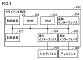
- FIG. 4 is a diagram showing an example of the hardware configuration of the client terminal 200.
- the client terminal 200 includes a control device 201, a ROM 202, a RAM 203, a communication interface 204, a display interface 205, an operation interface 207, and a storage device 220.
- the control device 201 controls the client terminal 200.
- the control device 201 is composed of, for example, at least one integrated circuit.
- An integrated circuit is composed of, for example, at least one CPU, at least one ASIC, at least one FPGA, or a combination thereof.
- An antenna (not shown) or the like is connected to the communication interface 204.
- the client terminal 200 exchanges data with an external communication device via the antenna.
- External communication equipment includes, for example, a sensor box 100.
- the display interface 205 is connected to the display 206, and sends an image signal for displaying an image to the display 206 in accordance with a command from the control device 201 or the like.
- the operation interface 207 is, for example, a USB (Universal Serial Bus) terminal and is connected to the input device 209.
- the operation interface 207 receives a signal indicating a user operation from the input device 209.
- the input device 209 is, for example, a mouse, a keyboard, a touch panel, or other device capable of accepting a user's input operation.
- the storage device 220 is a storage medium such as a hard disk or an external storage device, for example.
- the storage device 220 stores a program executed by the control device 201, but the program may be stored in another storage device accessible to the control device 201.
- FIG. 5 is a diagram showing an example of the hardware configuration of the mobile terminal 300.
- the mobile terminal 300 includes a control device 301, a RAM 303, a communication interface 304, a display 305, an input device 306, and a built-in memory 320.
- the control device 301 controls the mobile terminal 300.
- the control device 301 is composed of, for example, at least one integrated circuit.
- An integrated circuit is composed of, for example, at least one CPU, at least one ASIC, at least one FPGA, or a combination thereof.
- the mobile terminal 300 exchanges data with an external communication device via the antenna and the access point AP (FIG. 1).
- the external communication device includes, for example, a sensor box 100, a client terminal 200, and the like.
- the display 305 is realized by, for example, an organic EL (Electro Luminescence) display.
- the input device 306 is realized, for example, by a touch sensor superimposed on the display 305.
- the touch sensor receives various operations on the mobile terminal 300 by touch operations, and outputs the contents of the operations to the control device 301.
- the built-in memory 320 is, for example, a storage medium such as eMMC (Embedded MultiMediaCard).
- eMMC embedded MultiMediaCard
- the built-in memory 320 stores a program executed by the control device 301, but the program is stored in a storage device other than the built-in memory 320 if the storage device is accessible to the control device 301. May be good.
- FIG. 6 is a diagram showing an example of the hardware configuration of the management server 400.
- the management server 400 includes a control device 401, a ROM 402, a RAM 403, a communication interface 404, and a storage device 420.
- the control device 401 controls the management server 400.
- the control device 401 is composed of, for example, at least one integrated circuit.
- An integrated circuit is composed of, for example, at least one CPU, at least one ASIC, at least one FPGA, or a combination thereof.
- the management server 400 exchanges data with an external communication device via the antenna.
- the external communication device includes, for example, a sensor box 100 and a client terminal 200.
- the storage device 420 is a storage medium such as a hard disk or an external storage device, for example.
- the storage device 420 stores a program executed by the control device 401, which may be stored in another storage device accessible to the control device 401.
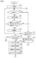
- FIG. 7 is a flowchart of an example of processing for displaying resident information.
- the display of information for each resident 20 is controlled according to the process of FIG.
- the information displayed is based on the biometric information and / or care call of each resident 20.
- Biological information includes at least one of vital information, behavioral information, and excretion information.
- the process of FIG. 7 is realized, for example, by the CPU of the control device 201 executing a given program.
- the program may be stored in the recording device 220, or may be stored in an external storage device accessible to the CPU of the control device 201.
- step S10 the control device 201 displays a list of information on each of the plurality of residents 20.
- FIG. 8 is a diagram showing an example of displaying a list of information of a plurality of residents 20.
- the display 206 displays the list display screen 800.
- the list display screen 800 includes a matrix 810.
- Each square of the matrix 810 represents the state of each resident 20 in color.
- the matrix 810 includes a total of 100 squares arranged in 10 columns and 10 rows. In one example, each square is associated with each resident 20.
- the control device 201 displays each square in a color corresponding to the state of the associated resident 20.
- the status of the resident 20 includes "normal”, “wake up”, “get out of bed”, “fall”, “fall”, “vital abnormality”, and “with care call”.
- “Wake up”, “get out of bed”, “fall” and “fall” are generated as action information.
- “Vital abnormality” indicates that the detection output of the vital sensor 540 shows an abnormal value.
- “With care call” indicates that the care call slave unit 500 has been operated.
- Another state of the resident 20 that is expected to be displayed is “excretion”.
- “With excretion” means, for example, that the value detected by the odor sensor 530 indicates an abnormal value corresponding to excretion.
- Normal indicates that the above behavior information or abnormal value has not been detected.
- the squares are displayed in white, and when the state is other than "normal", the squares are colored and displayed in a color other than white.
- Priority may be assigned to each of the two or more states. The type of the state to be displayed and the priority for each state may be predetermined or may be appropriately set by the director or the like.
- step S20 the control device 201 determines whether or not the state has changed in any of the occupants 20 to be displayed in the list.
- the control device 201 determines that the state of any of the occupants 20 has not changed (NO in step S20)
- the control device 201 advances control to step S60 and determines that the state of at least one resident 20 has changed (NO). YES in step S20), and the control proceeds to step S30.
- step S60 the control device 201 determines whether or not there has been an operation on the squares in the matrix 810.
- the “operation on the square” is, for example, a click operation or a touch operation on the square on the display 206. If the control device 201 determines that there is an operation on the square (YES in step S60), the control proceeds to step S70, and if not (NO in step S60), the control proceeds to step S80.
- step S70 the control device 201 displays a pop-up window corresponding to the square to be operated in step S60.
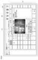
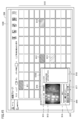
- FIG. 9 is a diagram showing an example of the display mode of the pop-up window.
- a pop-up window 910 is displayed on the matrix 810.
- the pop-up window 910 displays detailed information of the resident 20 associated with the square to be operated among the 100 squares of the matrix 810.
- the pop-up window 910 includes columns 911 and 912.
- Column 911 represents the number of the living room 10 and the name of the resident 20.
- Column 912 represents an image of the camera 105 installed in the living room 10.
- the pop-up window 910 includes a button 914, a comment field 915, a button 916, 917, and a field 919.
- the button 914 is operated to stop the change of the display according to the information from the sensor box 100 for a certain period of time.
- the control device 201 changes the color of the squares corresponding to each resident according to the behavior information or vital abnormality of each resident or the care call from each resident input from the sensor box 100.
- the control device 201 identifies a resident corresponding to the pop-up window 910 including the button 914, and displays the input from the sensor box 100 corresponding to the resident on the display 206 for a certain period of time. Stop using it for changes.
- the output of information from the sensor box 100 to the management server 400 and the client terminal 200 may be continued or stopped.
- the comment field 915 of the action information accepts the input of comments.
- the button 916 is operated to notify the mobile terminal 300 of the information in the pop-up window 910.
- the button 917 is operated when it is determined that it is unnecessary to deal with the resident 20 corresponding to the pop-up window 910.
- Column 919 displays behavioral information generated about the resident and / or an icon representing a care call from the resident. By checking the type of icon displayed in column 919, the director can easily understand the reason why the squares are colored for the resident.
- Column 918 represents resident information stored in advance in the management server 400 or the like for the resident 20.
- Resident information includes, for example, information on the need for long-term care (you can walk on your own, need walking assistance, etc.), information on the priority of long-term care, or information on medication (taking hypertension medication after breakfast, every meal). Later, taking cold medicine, etc.) is included.
- the director may refer to the resident information to determine the necessity of notification to the staff and / or to determine the content of the comment to be entered.
- step S80 the control device 201 determines whether or not an operation has been performed on the pop-up window 910. More specifically, the control device 201 displays the pop-up window 910 in step S70, returns control to step S20, and then operates on the pop-up window 910 displayed in step S70 in step S80. Determine if it was done.
- step S80 If the control device 201 determines that the operation for the pop-up window 910 has been performed (YES in step S80), the control proceeds to step S90, and if not (NO in step S80), the control returns to step S20.
- step S90 the control device 201 accepts the input of a comment for the comment field 915 of the pop-up window 910.
- An example of the content of a comment is an instruction to the staff.
- Another example is the communication of information about the resident 20 to be notified.
- the control device 201 accepts the designation of the notification destination mobile terminal 300.
- the staff 850 who can handle the resident 20 registers information indicating that the staff 850 can handle the client terminal 200 by using the mobile terminal 300 carried by the staff 850.
- the control device 201 may display the IDs of two or more registered mobile terminals 300 in the pop-up window 910, for example, as a pull-down menu.
- the director designates one or more mobile terminals 300 as notification destinations of information in the pop-up window 910 from the pull-down menu.
- step S110 the control device 201 notifies the mobile terminal 300 of (at least a part of) the information in the pop-up window 910.
- the control device 201 may control the step S110 on condition that the operation for the button 916 is received.
- the notification includes information indicating a room, which is shown in a pop-up window.
- the notification may include the comment received in step S90.
- step S110 the notification is transmitted to the mobile terminal 300 designated in step S100.
- the designation of the mobile terminal 300 in step S100 may be omitted.
- the notification is transmitted to the predetermined mobile terminal 300.
- step S120 the control device 201 erases the display of the pop-up window 910 to be operated in step S80 from the display 206. After that, control is returned to step S20.
- the control device 201 displays the pop-up window 910 (FIG. 9) when it receives a click operation on the square 811 of FIG. 8, and erases the display of the pop-up window 910 from the display 206 when it receives an operation on the button 916. To do.
- the coloring in the square 811 (FIG. 8) may be eliminated.
- control device 201 may erase the display of the pop-up window 910 from the display 206 in response to the operation of the button 917. That is, when the button 917 is operated, the control of steps S90 to S110 may be omitted, and the pop-up window 910 may be deleted in step S120.
- control device 201 may erase the display of the pop-up window 910 from the display 206 after a lapse of a given time from the start of the display of the pop-up window 910. That is, when a given time has elapsed from the start of the display of the pop-up window 910, the control of steps S90 to S110 may be omitted, and the pop-up window 910 may be deleted in step S120.
- step S30 the control device 201 updates the list display (matrix 810).
- the matrix 810 is updated so that the squares corresponding to the resident 20 are colored.
- FIG. 10 is a diagram for explaining an example of updating the list display.
- the squares 812 to 814 are colored in addition to the squares 811.
- the color of each square is determined according to the state of the resident corresponding to each square.
- the colored squares may include an icon representing a state corresponding to the color attached to each square.
- the square corresponding to the state "lighting” may include an icon representing the state "lighting”.
- control device 201 determines in step S40 whether or not a pop-up window is displayed on the updated square. If the control device 201 determines that the pop-up window is displayed on the updated square (YES in step S40), the control device 201 proceeds to control to step S50, otherwise (NO in step S40). Control proceeds to step S60.
- the updated squares (squares 812 to 814) are covered with the pop-up window 910. That is, the pop-up window 910 is displayed on the updated square.
- step S50 the control device 201 updates the screen so that the information to be displayed in the updated squares is displayed on the display 206. After that, control is returned to step S20.
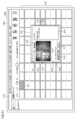
- FIG. 11 is a diagram showing an example of the screen after the update in step S60.
- the list display screen 1100 of FIG. 11 represents the screen after the update when the squares 812 to 814 are updated from the state shown in FIG.
- the list display screen 1100 includes a column 1110.
- Column 1110 represents the character string "3 remaining cases: Room_102_Mr. Yamada_fall / Room_202_Mr. Yamamoto_wake up_fall / Room_217_Mr. Yamanaka_wake up”. "Remaining 3 cases” represents the number of updated squares (squares 812 to 814) in the area covered by the pop-up window 910.
- Each of "Room_102_Yamada-san_fall”, “Room_202_Yamamoto-san_wake-up_fall” and “Room_217_Yamanaka-san_wake-up” represents the resident information corresponding to each of the squares 812 to 814.
- the character string in the column 1110 is displayed at a position that does not overlap with the matrix 810 and the pop-up window 910.
- the matrix 810 is an example of a first region representing information on each of a plurality of monitoring targets.
- the pop-up window 910 is an example of a second area representing additional information to be watched corresponding to the squares manipulated in the matrix 810.
- Column 1110 is an example of a third area representing information on the watch target whose state has changed after the pop-up window 910 is displayed.
- each square of the matrix 810 represents only the state of each resident by its color.
- the state of each resident may be represented by a display pattern (lighting, blinking, extinguishing, etc.) of each square, not by color or in combination with color.
- the pop-up window 910 displays the captured image of the camera 105 in the column 912 as detailed information of the resident.
- the vital information of the resident body temperature detected by the vital sensor 540, heart rate detected by the Doppler sensor 106, etc.
- column 918 may be displayed in column 918.
- Column 1110 displays information outside the matrix 810 and the pop-up window 910 that should be displayed in the matrix 810 for residents whose state has changed after the display of the pop-up window 910, regardless of the display of the pop-up window 910. Can be displayed. That is, when the portion to be changed in the matrix 810 due to the change in the resident's state cannot be visually recognized by the display of the pop-up window 910, the change is displayed in the column 1110.
- the director moves the pop-up window 910 to display the squares corresponding to the resident in the matrix 810 in order to see additional information of the resident in column 1110 (for example, Mr. Yamada of Room_102). Click the square. As a result, a new pop-up window for the resident is displayed.
- the control device 201 Upon receiving the notification instruction to the mobile terminal 300 for the newly displayed pop-up window, the control device 201 sends a notification about the resident (for example, Mr. Yamada of Room_102) to the mobile terminal 300, and then the control device 201 sends a notification to the mobile terminal 300. , Clear the newly displayed pop-up window. As a result, the display 206 is updated as shown in FIG.
- FIG. 12 is a diagram showing an example of an updated screen with respect to the screen of FIG. Compared with FIG. 11, the list display screen 1200 of FIG. 12 has the display of column 1110 updated.
- the character string "2 remaining cases: Room_202_Mr. Yamamoto_Wake up_Fall / Room_217_Mr. Yamanaka_Wake up” is displayed. That is, in FIG. 12, the number of remaining cases is one less than that in FIG. 11, and the information of Mr. Yamada of Room_102 is not included. This is based on the fact that the notification was sent to the mobile terminal 300 about Mr. Yamada of Room_102 as described above.
- the control device 201 can update the display of the third area in response to the transmission of the notification to the mobile terminal 300.
- the display of the third area may be updated according to the "no action required" button (button 917 in FIG. 9) for the pop-up window. That is, if the "no action required" button is transmitted in the pop-up window of the resident whose state has changed, the third area can be updated so that the resident's information is deleted.
- FIG. 13 is a diagram showing an example of a display mode when the list display changes from the state shown in FIG.
- the third area is displayed in the pop-up window. More specifically, in step S40, when the display 206 displays the pop-up window 910 as shown in FIG. 9, the control device 201 has the squares 812 to 814 covered by the pop-up window 910. When the display color is changed, the list display screen 1300 of FIG. 13 is displayed in step S50.
- the list display screen 1300 includes a pop-up window 1310 as compared with the list display screen 1100 of FIG.
- Pop-up window 1310 includes column 1311 below buttons 916,917.
- the control device 201 displays the information displayed in the column 1110 in the example of FIG. 11 in the column 1311. That is, in column 1311, when the state of the resident corresponding to the square located in the portion covered by the pop-up window 1310 changes in the matrix 810, the change in the state of the resident is displayed in column 1311. ..
- column 1311 is an example of the third region.
- Column 1311 is located within the pop-up window 1310. Since the pop-up window 1310 is displayed according to the operation of the director, it is highly possible that the director is paying attention to the pop-up window 1310. By displaying the column 1311 in the area (pop-up window 1310) that the director is likely to be paying attention to, the example of FIG. 13 is more surely located in the area covered by the pop-up window 1310. Can make the director aware of the changes in the window.
- FIG. 14 is a diagram showing an example of an updated screen with respect to the screen of FIG. 13.
- the control device 201 displays the screen of FIG. 14 when a notification is sent to the mobile terminal 300 about the state of the resident (for example, Mr. Yamada of Room_102).
- FIG. 15 is a diagram showing an example of a list display screen.
- the list display screen 1500 of FIG. 15 includes a pop-up window 1510.
- the pop-up window that has already been displayed moves so that it does not overlap with the squares in the list that correspond to the resident whose state has changed. More specifically, when the control device 201 is displaying the list display screen 1500 of FIG. 15 and the display color of the squares covered by the pop-up window 1510 is changed in step S40, the step In S50, the display of the display 206 is updated as shown in FIG.
- FIG. 16 is a diagram showing an example of a screen updated from the state shown in FIG.
- the list display screen 1600 of FIG. 16 includes a pop-up window 1510.
- the dashed frame 1601 represents the position of the pop-up window 1510 in FIG.
- the arrow 1602 indicates the moving direction of the pop-up window.
- the squares 815 and 816 are further colored and displayed as compared with FIG. Before moving (FIG. 15), the square 816 was covered with the pop-up window 1510 (FIG. 15). Since the pop-up window 1510 is moved according to the arrow 1602, the squares 816 are visible on the list display screen 1600 of FIG.
- the pop-up window 1510 is located not only in the squares 816 but also in the squares 811 to 814 that have been displayed before the display of the pop-up window 1510. As a result, it is more surely prevented that the display of the pop-up window of one resident on the list display screen interferes with the display of the status of another resident.
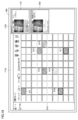
- FIG. 17 is a diagram showing an example of a display mode when the list display changes from the state shown in FIG.
- the pop-up display field 1720 appears by reducing the matrix 810 in the list display screen 1700.
- the pop-up window 1721 is displayed in the pop-up display field 1720.
- the control device 201 has a grid (square 812) covered with the pop-up window 910.
- the display of the display 206 is updated as shown in FIG. 17 in step S50.
- FIG. 18 is a diagram showing an example of a state after the display of FIG. 17 has been updated.
- the control device 201 When operated on any of the squares 811 to 817 of FIG. 17, the control device 201 displays the pop-up window 1821 corresponding to the operated square in the pop-up display field 1720 as shown in FIG. To do. This allows the director to view multiple pop-up windows at the same time, thereby deciding which staff to take charge of which resident while simultaneously viewing the detailed status of the multiple occupants.
- the pop-up window is displayed outside the matrix 810.
- the director can concentrate on checking the resident information displayed in each pop-up window without confusing it with the information of other occupants.
- the control device 201 displays the pop-up window 1510 in step S50 as shown in FIG. At this time, at least a part of the pop-up window 1510 is displayed in the list display screen 1500 so as to overlap the matrix 810. In this state, the pop-up window 1510 does not overlap all the colored squares 811-814. Therefore, control is returned from step S40 to step S20 without proceeding to step S50.
- control device 201 reduces the matrix 810 of the list display screen as shown in FIG. 17 in step S50, and pops up a window in the pop-up display field 1720. Display 1721.
- FIG. 19 is a diagram showing an example of a screen after updating from the state shown in FIG. In FIG. 19, the squares 811 to 814 are colored on the list display screen 1710, and two pop-up windows 1721 and 1821 are displayed in the pop-up display field 1720.
- the display 206 is updated as shown in FIG. More specifically, when the control device 201 determines in step S50 that a pop-up window cannot be added to the list display screen 1500 of FIG. 15 so as not to overlap any of the squares 811 to 814, As shown in FIG. 19, two pop-up windows are displayed in the pop-up display field.
- the reduction of the matrix 810 can be avoided as much as possible.
- the matrix 810 is reduced to display one or more pop-up windows so that they do not overlap the colored squares in the matrix 810.
- the control device 201 may delete the display of the pop-up window display field 1720 from the display 206. For example, when the pop-up window displayed in the pop-up window display field 1720 disappears due to the deletion of the pop-up window (step S120), the display of the pop-up window display field 1720 becomes unnecessary.
- the control device 201 may enlarge the display of the matrix 810 as the pop-up window display field 1720 is erased. For example, in the display 206, when the number of pop-up windows increases, the matrix 810 is reduced as shown in FIG. 17 and the like, and when the number of pop-up windows decreases, the matrix 810 is expanded as shown in FIG. 8 and the like. May be done. That is, the control device 201 may expand the matrix 810 as the pop-up window disappears.
- each of the sensor boxes 100A, 100B ... may output data directly to each of the client terminals 200A, 200B ... Without going through the management server 400.
- the number of client terminals may be one.
- various "programs” may be provided by being incorporated into a part of an arbitrary program, not as a single program.
- Various "programs” can be realized by the cooperation of any plurality of programs.
- the first program when the control device 101 of the sensor box 100 implements the functions described herein by executing the first program, the first program is a module of a part of the second program. You may be using. Even if the first program does not include some modules for realizing the function, if it mainly contributes to the realization of the function, it deviates from the purpose of the program for realizing the function. It's not something to do.
- some or all of the functions described herein may be implemented by dedicated hardware.
- the device that provides the functions described in the present specification may be provided by an external device as a so-called cloud service in part or all of the functions.
Landscapes
- Business, Economics & Management (AREA)
- Engineering & Computer Science (AREA)
- Physics & Mathematics (AREA)
- General Physics & Mathematics (AREA)
- Theoretical Computer Science (AREA)
- Tourism & Hospitality (AREA)
- Emergency Management (AREA)
- General Engineering & Computer Science (AREA)
- Health & Medical Sciences (AREA)
- Marketing (AREA)
- Strategic Management (AREA)
- Economics (AREA)
- General Health & Medical Sciences (AREA)
- Human Resources & Organizations (AREA)
- Human Computer Interaction (AREA)
- Primary Health Care (AREA)
- Child & Adolescent Psychology (AREA)
- General Business, Economics & Management (AREA)
- Alarm Systems (AREA)
- Emergency Alarm Devices (AREA)
- User Interface Of Digital Computer (AREA)
- Medical Treatment And Welfare Office Work (AREA)
- Image Analysis (AREA)
Priority Applications (3)
| Application Number | Priority Date | Filing Date | Title |
|---|---|---|---|
| JP2021513557A JP7487735B2 (ja) | 2019-04-11 | 2020-03-25 | 情報を表示する方法、プログラム、および情報処理装置 |
| JP2024074410A JP7740423B2 (ja) | 2019-04-11 | 2024-05-01 | 情報を表示する方法、プログラム、および情報処理装置 |
| JP2025146002A JP2025179157A (ja) | 2019-04-11 | 2025-09-03 | 情報を表示する方法、プログラム、および情報処理装置 |
Applications Claiming Priority (2)
| Application Number | Priority Date | Filing Date | Title |
|---|---|---|---|
| JP2019075285 | 2019-04-11 | ||
| JP2019-075285 | 2019-04-11 |
Publications (1)
| Publication Number | Publication Date |
|---|---|
| WO2020209066A1 true WO2020209066A1 (ja) | 2020-10-15 |
Family
ID=72751562
Family Applications (1)
| Application Number | Title | Priority Date | Filing Date |
|---|---|---|---|
| PCT/JP2020/013286 Ceased WO2020209066A1 (ja) | 2019-04-11 | 2020-03-25 | 情報を表示する方法、プログラム、および情報処理装置 |
Country Status (2)
| Country | Link |
|---|---|
| JP (3) | JP7487735B2 (https=) |
| WO (1) | WO2020209066A1 (https=) |
Cited By (1)
| Publication number | Priority date | Publication date | Assignee | Title |
|---|---|---|---|---|
| JP2023000589A (ja) * | 2021-06-18 | 2023-01-04 | コニカミノルタ株式会社 | 情報処理システム、情報処理装置、制御方法、および制御プログラム |
Families Citing this family (1)
| Publication number | Priority date | Publication date | Assignee | Title |
|---|---|---|---|---|
| WO2020209066A1 (ja) * | 2019-04-11 | 2020-10-15 | コニカミノルタ株式会社 | 情報を表示する方法、プログラム、および情報処理装置 |
Citations (6)
| Publication number | Priority date | Publication date | Assignee | Title |
|---|---|---|---|---|
| JP2005151540A (ja) * | 2003-10-14 | 2005-06-09 | Aiphone Co Ltd | ナースコールシステム |
| JP2008293301A (ja) * | 2007-05-25 | 2008-12-04 | Sysmex Corp | 患者異常通知システムおよび集中監視装置 |
| JP2014158637A (ja) * | 2013-02-21 | 2014-09-04 | Carecom Co Ltd | ナースコールシステム |
| JP2015191526A (ja) * | 2014-03-28 | 2015-11-02 | エコナビスタ株式会社 | 情報処理装置、プログラム、情報処理システム及び情報表示方法 |
| JP3202674U (ja) * | 2015-11-24 | 2016-02-18 | 株式会社メイク | 非接触式離床管理システム |
| JP2016059704A (ja) * | 2014-09-19 | 2016-04-25 | アイホン株式会社 | ナースコールシステム |
Family Cites Families (11)
| Publication number | Priority date | Publication date | Assignee | Title |
|---|---|---|---|---|
| JP2003256459A (ja) | 2002-02-28 | 2003-09-12 | Hitachi Ltd | ポップアップ表示方法及びプログラム |
| JP2004358218A (ja) * | 2003-05-09 | 2004-12-24 | Keakomu:Kk | ナースコールシステムのセンタ装置 |
| JP2007199819A (ja) | 2006-01-24 | 2007-08-09 | Fujitsu Ltd | メッセージ表示制御プログラムおよびメッセージ表示制御装置 |
| JP2010051545A (ja) | 2008-08-28 | 2010-03-11 | Aiphone Co Ltd | 看護支援システム |
| JP2010284245A (ja) * | 2009-06-10 | 2010-12-24 | Eikoh Denshi Kogyo Kk | 安否確認システム |
| JP5912561B2 (ja) | 2012-01-19 | 2016-04-27 | 株式会社ケアコム | ナースコールシステム |
| JP6144567B2 (ja) | 2013-07-31 | 2017-06-07 | 株式会社ケアコム | ナースコールシステム |
| JP6703892B2 (ja) | 2016-05-10 | 2020-06-03 | 株式会社まもるーの | 情報処理装置及び情報処理プログラム |
| JP6842009B2 (ja) | 2017-05-26 | 2021-03-17 | 株式会社ケアコム | ナースコールシステム |
| JPWO2019216045A1 (ja) | 2018-05-07 | 2021-06-10 | コニカミノルタ株式会社 | システム、およびシステムの制御方法 |
| WO2020209066A1 (ja) | 2019-04-11 | 2020-10-15 | コニカミノルタ株式会社 | 情報を表示する方法、プログラム、および情報処理装置 |
-
2020
- 2020-03-25 WO PCT/JP2020/013286 patent/WO2020209066A1/ja not_active Ceased
- 2020-03-25 JP JP2021513557A patent/JP7487735B2/ja active Active
-
2024
- 2024-05-01 JP JP2024074410A patent/JP7740423B2/ja active Active
-
2025
- 2025-09-03 JP JP2025146002A patent/JP2025179157A/ja active Pending
Patent Citations (6)
| Publication number | Priority date | Publication date | Assignee | Title |
|---|---|---|---|---|
| JP2005151540A (ja) * | 2003-10-14 | 2005-06-09 | Aiphone Co Ltd | ナースコールシステム |
| JP2008293301A (ja) * | 2007-05-25 | 2008-12-04 | Sysmex Corp | 患者異常通知システムおよび集中監視装置 |
| JP2014158637A (ja) * | 2013-02-21 | 2014-09-04 | Carecom Co Ltd | ナースコールシステム |
| JP2015191526A (ja) * | 2014-03-28 | 2015-11-02 | エコナビスタ株式会社 | 情報処理装置、プログラム、情報処理システム及び情報表示方法 |
| JP2016059704A (ja) * | 2014-09-19 | 2016-04-25 | アイホン株式会社 | ナースコールシステム |
| JP3202674U (ja) * | 2015-11-24 | 2016-02-18 | 株式会社メイク | 非接触式離床管理システム |
Cited By (1)
| Publication number | Priority date | Publication date | Assignee | Title |
|---|---|---|---|---|
| JP2023000589A (ja) * | 2021-06-18 | 2023-01-04 | コニカミノルタ株式会社 | 情報処理システム、情報処理装置、制御方法、および制御プログラム |
Also Published As
| Publication number | Publication date |
|---|---|
| JPWO2020209066A1 (https=) | 2020-10-15 |
| JP7740423B2 (ja) | 2025-09-17 |
| JP2025179157A (ja) | 2025-12-09 |
| JP7487735B2 (ja) | 2024-05-21 |
| JP2024103493A (ja) | 2024-08-01 |
Similar Documents
| Publication | Publication Date | Title |
|---|---|---|
| JP7740423B2 (ja) | 情報を表示する方法、プログラム、および情報処理装置 | |
| US10446007B2 (en) | Watching system and management server | |
| JP2021086605A (ja) | イベントの防止及び予測のためのシステム及び方法、コンピュータ実施方法、プログラム、及びプロセッサ | |
| JP7234572B2 (ja) | ケアシステム、その管理方法、およびプログラム | |
| WO2020003706A1 (ja) | 制御プログラム、レポート出力方法、およびレポート出力装置 | |
| JP2020098619A (ja) | 被監視者監視システム、情報処理装置およびプログラム | |
| WO2021215207A1 (ja) | 被介護者の情報を提供するためにコンピューターで実行される方法、プログラム、および、情報提供装置 | |
| CN113892945B (zh) | 健康监护系统中多雷达的关联控制方法及控制装置 | |
| JP7172376B2 (ja) | 情報提供装置、情報提供システム、情報提供方法、及びプログラム | |
| JP6881427B2 (ja) | 端末装置およびプログラム | |
| CN111722535A (zh) | 安全监控方法、装置、计算机设备和存储介质 | |
| WO2020003951A1 (ja) | コンピューターで実行されるプログラム、情報処理装置、および、コンピューターで実行される方法 | |
| JP7255359B2 (ja) | 情報を通知するためのプログラム、情報通知装置、および、情報を通知するためにコンピューターで実行される方法 | |
| JP2023003917A (ja) | 推定装置、学習装置、推定システム、推定方法、及び、プログラム | |
| US11513007B2 (en) | Notification control device, notification control system, and notification control method | |
| JP7480475B2 (ja) | 通知制御システム、通知制御方法、及びプログラム | |
| US20210241927A1 (en) | System and method for monitoring via smart devices | |
| JPWO2020075675A1 (ja) | ケアシステムの管理方法および管理装置、ならびにプログラム | |
| WO2020009107A1 (ja) | 情報処理装置、センサーボックス、および、プログラム | |
| JP2025154486A (ja) | 生活見守りシステム及びプログラム | |
| JP7413669B2 (ja) | ケア管理方法、プログラム、ケア管理装置、および、ケア管理システム | |
| JP7758035B2 (ja) | 行動検知システムおよび行動検知プログラム | |
| TWI622024B (zh) | 智慧影像式監測告警裝置 | |
| JP7487577B2 (ja) | 介護スタッフを割り当てるためにコンピューターで実行される方法、プログラム、情報処理装置、および見守りシステム | |
| JP2021196992A (ja) | 見守りシステム、情報処理装置、およびプログラム |
Legal Events
| Date | Code | Title | Description |
|---|---|---|---|
| 121 | Ep: the epo has been informed by wipo that ep was designated in this application |
Ref document number: 20787145 Country of ref document: EP Kind code of ref document: A1 |
|
| ENP | Entry into the national phase |
Ref document number: 2021513557 Country of ref document: JP Kind code of ref document: A |
|
| NENP | Non-entry into the national phase |
Ref country code: DE |
|
| 122 | Ep: pct application non-entry in european phase |
Ref document number: 20787145 Country of ref document: EP Kind code of ref document: A1 |